


Model 4200A-SCS
Prober and
External Instrument Control
4200A-913-01 Rev. B June 2022
tek.com/keithley
*P4200A-913-01B*
4200A-913-01B

Parameter Analyzer
Model 4200A-SCS
Prober and External Instrument Cont rol

© 2022, Keithley Instruments
Cleveland, Ohio, U.S.A.
All rights reserved.
Any unauthorized reproduction, photocopy, or use of the information herein, in whole or in part,
without the prior written approval of Keithley Instruments is strictly prohibited.
All Keithley Instruments product names are trademarks or registered trademarks of Keithley
Instruments, LLC. Other brand names are trademarks or registered trademarks of their r espective
holders.
Actuate
®
Copyright © 1993-2003 Actuate Corporation.
All Rights R eserved.
Microsoft, Visual C++, Excel, and Windows are either registered trademarks or trademarks of
Microsoft Corporation in the United States and/or other countries.
Document number: 4200A-913-01 Rev. B June 2022

Safety precaut ions
The following safety precautio ns should be observed before using this product and any associated ins tr um enta tion . Altho ugh
some instruments and accessories would normally be used with nonhazardous voltages, there are situations where hazardous
conditions may be present.
This product is intended for use by personnel who recognize shock hazards and are familiar with the safety precautions required
to avoid possible injury. Read and follow all installation, operation, and maintenance information carefully before using the
product. Refer to the user documentation for complete product specification s.
If the product is used in a manner not specified, the protection provided by the product warranty may be impaired.
The types of product users are:
Responsible body is the individual or group responsible for the use and maintenance of equipment, for ensuring that the
equipment is operated within its specifications and operating limits, and for ensuring that operators are adequately trained.
Operators use the product for its intended function. They must be trained in electrical safety procedures and proper use of the
instrument. They must be protected from electric shock and contact with hazardous live circuits.
Maintenance personnel perform routine procedures on the product to keep it operating properly, for example, setting the line
voltage or replacing consumable materials. Maintenance procedures are described in the user documentation. The procedures
explicitly state if the operator may perform them. Otherwise, they should be performed only by service personnel.
Service personnel are trained to work on live circuits, perform safe installations, and repair products. Only properly trained
service personnel may perform installation and service procedures.
Keithley products are designed for use with electrical signals that are measurement, control, and data I/O connections, with low
transient overvoltages, and must not be directly connected to mains voltage or to voltage sources with high transient
overvoltages. Measurement Category II (as referenced in IEC 60664) connections require protection for high transient
overvoltages often associated with local AC mains connections. Certain Keithley measuring instruments may be connected to
mains. These instruments will be marked as category II or higher.
Unless explicitly allowed in the specifications, operating manual, and instrument labels, do not connect any instrument to mains.
Exercise extreme caution when a shock hazard is present. Lethal voltage may be present on cable connector jacks or test
fixtures. The American National Standards Institute (ANSI) states that a shock hazard exists when voltage levels greater than
30 V RMS, 42.4 V peak, or 60 VDC are present. A good safety practice is to expect that hazardous voltage is present in any
unknown circuit before measuring.
Operators of this product must be protected from electric shock at all times. The responsible body must ensure that operators
are prevented access and/or insulated from every connection point. In some cases, connections must be exposed to potential
human contact. Product operators in these circumstances must be trained to protect themselves from the risk of electric shock. If
the circuit is capable of operating at or above 1000 V, no conductive part of the circuit may be exposed.
Do not connect switching cards directly to unlimited power circuits. They are intended to be used with impedance-limited
sources. NEVER connect switching cards directly to AC mains. When connecting sources to switching cards, install protective
devices to limit fault current and voltage to the card.
Before operating an instrument, ensure that the line cord is connected to a properly-grounded power receptacle. Inspect the
connecting cables, test leads, and jumpers for possible wear, cracks, or breaks before each use.
When installing equipment where access to the main power cord is restricted, such as rack mounting, a separate main input
power disconnect device must be provided in close proximity to the equipment and within easy reach of the operator.
For maximum safety, do not touch the product, test cables, or any other instruments while power is applied to the circuit under
test. ALWAYS remove power from the entire test system and discharge any capacitors before: connecting or disconnecting
cables or jumpers, installing or removing switching cards, or making internal changes, such as installing or removing jumpers.
Do not touch any object that could provide a current path to the common side of the circuit under test or power line (earth)
ground. Always make measurements with dry hands while standing on a dry, insulated surface capable of withstanding the
voltage being measured.
For safety, instruments and accessories must be used in accordance with the operating instructions. If the instruments or
accessories are used in a manner not specified in the operating instructions, the protection provided by the equipment may be
impaired.
Do not exceed the maximum signal levels of the instruments and accessories. Maximum signal levels are defined in the
specifications and operating information and shown on the instrument panels, test fixture panels, and switching cards.
When fuses are used in a product, replace with the same type and rating for continued protection against fire hazard.
Chassis connections must only be used as shield connections for measuring circuits, NOT as protective earth (safety ground)
connections.
If you are using a test fixture, keep the lid closed while power is applied to the device under test. Safe operation requires the use
of a lid interlock.
If a screw is present, connect it to protective earth (safety ground) using the wire recommended in the user documentation.
The symbol on an instrument means caution, risk of hazard. The user must refer to the operating instructions located in the
user documentation in all cases where the symbol is mark ed on the instr u ment .
The symbol on an instrument means warning, risk of electric shock. Use standard safety precautions to avoid personal
contact with these voltages.
The symbol on an instrument shows that the surface may be hot. Avoid personal contact to prevent burns.
The symbol indicates a connection terminal to the equipment frame.
If this symbol is on a product, it indicates that mercury is present in the display lamp. Please note that the lamp must be
properly disposed of according to federal, state, and local laws.
The WARNING heading in the user documentation explains hazar ds that mi ght result in personal injury or death. Always read
the associated information very carefully before performing the indicated procedure.
The CAUTION heading in the user documentation explains h azard s that coul d dama ge the instrument. Such damage may
invalidate the warranty.
The CAUTION heading with the symbol in the user documentation explains hazards that could result in moderate or minor
injury or damage the instrument. Always read the associated information very carefully before performing the indicated
procedure. Damage to the instrument may invalidate the warranty.
Instrumentation and accessories shall not be connected to humans.
Before performing any maintenance, disconnect the line cord and all test cables.
To maintain protection from electric shock and fire, repl ace m ent comp one nts in mai ns cir cu its — inc lud ing the power
transformer, test leads, and input jacks — must be purchased from Keithley. Standard fuses with applicable national safety
approvals may be used if the rating and type are the same. The detachable mains power cord provided with the instrument may
only be replaced with a similarly rated power cord. Other components that are not safety-related may be purchased from other
suppliers as long as they are equivalent to the original component (not e that se lect ed part s shou ld be purch ase d only thro ugh
Keithley to maintain accuracy and functionality of the product). If you are unsure about the applicability of a replacement
component, call a Keithley office for information.
Unless otherwise noted in product-specific literature, Keithley instruments are designed to operate indoors only, in the following
environment: Altitude at or below 2,000 m (6,562 ft); temperature 0 °C to 50 °C (32 °F to 122 °F); and pollution degree 1 or 2.
To clean an instrument, use a cloth dampened with deionized water or mild, water-based cleaner. Clean the exterior of the
instrument only. Do not apply cleaner directly to the instrument or allow liquids to enter or spill on the instrument. Products that
consist of a circuit board with no case or chassis (e.g., a data acquisition board for installation into a computer) should never
require cleaning if handled according to instructions. If the board becomes contaminated and operation is affected, the board
should be returned to the factory for proper cleaning/servicing.
Safety precaution revision as of June 2018.

Table of contents
Introduction ............................................................................................................... 1-1
Introduction .......................................................................................................................... 1-1
Using switch matrices .............................................................................................. 2-1
Typical test systems using a switch matrix .......................................................................... 2-1
Matrix card types ....................................................................................................................... 2-2
Switch matrix mainframes ......................................................................................................... 2-6
Switch matrix connections.................................................................................................... 2-6
Typical SMU matrix card connections ....................................................................................... 2-6
Typical preamplifier matrix card connections ............................................................................ 2-8
Typical CVU matrix card connections ....................................................................................... 2-9
Typical CVU test connections to a DUT .................................................................................. 2-11
Connection scheme settings .............................................................................................. 2-12
Row-column or instrument card settings ................................................................................. 2-12
Switch matrix control .......................................................................................................... 2-16
Signal paths to a DUT ........................................................................................................ 2-16
4200A-SCS signal paths ......................................................................................................... 2-17
C-V Analyzer signal paths ....................................................................................................... 2-20
Keysight Model 8110A pulse generator signa l pat h ................................................................ 2-23
Use KCon to add a switch matrix to the system ................................................................ 2-24
Step 1. Exit Clarius and open KCon ........................................................................................ 2-24
Step 2. Add a test fixture or probe station ............................................................................... 2-25
Step 3. Add switching system mainframe ............................................................................... 2-27
Step 4. Set GPIB address ....................................................................................................... 2-28
Step 5. Configure the instrument connection scheme ............................................................. 2-29
Step 6. Assign switch cards to mainframe slots ...................................................................... 2-29
Step 7. Set matrix card properties ........................................................................................... 2-30
Step 8. Save configuration ...................................................................................................... 2-31
Step 9. Close KCon and open Clarius ..................................................................................... 2-31
Switch matrix control example ........................................................................................... 2-31
Set up and run a switch matrix in Clarius ................................................................................ 2-32
Matrixulib user library ......................................................................................................... 2-33
ConnectPins user module ....................................................................................................... 2-33
Configure and use a Series 700 Switching System ................................................ 3-1
Introduction .......................................................................................................................... 3-1
Equipment required .............................................................................................................. 3-2
Device connections .............................................................................................................. 3-2
Connect the 7072 to the DUT.................................................................................................... 3-3
Connect the 4200A-SCS to the 7072 ........................................................................................ 3-4
Update the switch configuration in KCon ............................................................................. 3-5
Set up the measurements in Clarius .................................................................................... 3-9
Create a new project ............................................................................................................... 3-10
Add a device ........................................................................................................................... 3-10
Add the connectpins action ..................................................................................................... 3-11
Configure the connectpins action ............................................................................................ 3-11

Table of contents Model 4200A-SCS Prober and External Instrument Control
Search for and add existing tests from the Test Library .......................................................... 3-13
Run the project and view the tests .......................................................................................... 3-14
Using a Model 590 C-V Analyzer .............................................................................. 4-1
Introduction .......................................................................................................................... 4-1
C-V measurement basics ..................................................................................................... 4-1
Capacitance measureme nt tes ts ......................................................................................... 4-2
Connections ......................................................................................................................... 4-2
Signal connections .................................................................................................................... 4-3
Triaxial connectors .................................................................................................................... 4-3
GPIB connections ..................................................................................................................... 4-4
Cable compensation ............................................................................................................ 4-4
Cable compensation user modules ........................................................................................... 4-5
Using KCon to add a 590 C-V Analyzer to system .............................................................. 4-5
Model 590 test examples ..................................................................................................... 4-5
Cable compensation example ................................................................................................... 4-6
C-V sweep example ................................................................................................................ 4-10
KI590ulib user library ......................................................................................................... 4-12
CableCompensate590 user module ........................................................................................ 4-12
Cmeas590 user module .......................................................................................................... 4-15
CtSweep590 user module ....................................................................................................... 4-18
CvPulseSweep590 user module ............................................................................................. 4-22
CvSweep590 user module ...................................................................................................... 4-26
DisplayCableCompCaps590 user module .............................................................................. 4-30
LoadCableCorrectionConstants .............................................................................................. 4-32
SaveCableCompCaps590 user module .................................................................................. 4-33
Using a Keysight 4284/4980A LCR Meter ................................................................ 5-1
Introduction .......................................................................................................................... 5-1
C-V measurement basics .......................................................................................................... 5-1
Capacitance measurement tes ts ............................................................................................... 5-2
Signal connections .................................................................................................................... 5-3
GPIB connections ..................................................................................................................... 5-5
Using KCon to add a Keysight LCR Meter to the system .................................................... 5-6
Model 4284A or 4980A C-V sweep test example ................................................................ 5-6
HP4284ulib user library ........................................................................................................ 5-8
CvSweep4284 User Module...................................................................................................... 5-9
Cmeas4284 User Module........................................................................................................ 5-11
Using a Model 82 C-V System .................................................................................. 6-1
Introduction .......................................................................................................................... 6-1
Capacitance measureme nt tes ts ......................................................................................... 6-2
C-t measur ements ..................................................................................................................... 6-2
Simultaneous C-V measurements ............................................................................................. 6-3
Cable compensation ............................................................................................................ 6-5
Cable compensation user modules ........................................................................................... 6-6
Connections ......................................................................................................................... 6-6

Model 4200A-SCS Prober and External Instrument Control Table of contents
Front-panel connections ............................................................................................................ 6-6
Rear-panel connections ............................................................................................................ 6-7
Make power and GPIB connections .......................................................................................... 6-8
Using KCon to add Model 82 C-V System ........................................................................... 6-9
Model 82 projects ................................................................................................................. 6-9
Cable compensation tests ....................................................................................................... 6-10
Capacitance tests .................................................................................................................... 6-13
Formulas for capacitance tests ............................................................................................... 6-21
Choosing the right parameters ........................................................................................... 6-25
Optimal C-V measurement par amet ers ................................................................................... 6-25
Determining the optimal delay time ......................................................................................... 6-27
Correcting residual errors ........................................................................................................ 6-29
ki82ulib user library ............................................................................................................ 6-30
Abortmodule82 ........................................................................................................................ 6-31
CableCompensate82 user module .......................................................................................... 6-31
CtSweep82 user module ......................................................................................................... 6-34
DisplayCableCompCaps82 user module ................................................................................ 6-37
QTsweep82 user module ........................................................................................................ 6-39
SaveCableCompCaps82 user modu le .................................................................................... 6-42
SIMCVsweep82 user module .................................................................................................. 6-45
Simultaneous C-V analysis ................................................................................................ 6-48
Analysis methods .................................................................................................................... 6-48
Basic device parameters ......................................................................................................... 6-49
Doping profile .......................................................................................................................... 6-55
Interface trap density ............................................................................................................... 6-57
Mobile ion charge concentration ............................................................................................. 6-58
Generation velocity and generation lifetime (Zerbst plot) ........................................................ 6-61
Constants, symbols, and equations used for analysis ............................................................. 6-63
Summary of analysis equations .............................................................................................. 6-65
References .............................................................................................................................. 6-67
Bibliography of C-V Measurements ......................................................................................... 6-67
Articles and Papers ................................................................................................................. 6-68
Using a Keysight 8110A/8111A Pulse Generator .................................................... 7-1
Introduction .......................................................................................................................... 7-1
Pulse generator tests ........................................................................................................... 7-2
Signal connections ............................................................................................................... 7-2
Triaxial connections .................................................................................................................. 7-2
Probe station and test fixture connectio ns ................................................................................ 7-3
Switch matrix connections ......................................................................................................... 7-3
GPIB connections ................................................................................................................ 7-5
Using KCon to add a Keysight pulse generator to the system ............................................ 7-5
HP8110ulib user library ........................................................................................................ 7-5
PguInit8110 user module .......................................................................................................... 7-6
PguSetup8110 user module ...................................................................................................... 7-7
PguTrigger8110 user module .................................................................................................... 7-9
Set up a probe station .............................................................................................. 8-1
Prober control overview ....................................................................................................... 8-1
Supported probers .................................................................................................................... 8-4
PRBGEN user modules ............................................................................................................ 8-4

Table of contents Model 4200A-SCS Prober and External Instrument Control
Example test execution sequence: prob esi tes proj ect .............................................................. 8-6
Example test execution sequence: probesubsites project ......................................................... 8-6
Understanding site coordinate information .......................................................................... 8-7
Reference site (die) ................................................................................................................... 8-7
Probe sites (die) ........................................................................................................................ 8-8
Chuck movement ...................................................................................................................... 8-8
PRBGEN user library ......................................................................................................... 8-11
PrInit ........................................................................................................................................ 8-11
PrChuck .................................................................................................................................. 8-12
PrSSMovNxt ............................................................................................................................ 8-13
PrMovNxt ................................................................................................................................ 8-14
Tutorial: Control a probe station ......................................................................................... 8-16
Test system connections ......................................................................................................... 8-17
KCon setup ............................................................................................................................. 8-17
Test flow .................................................................................................................................. 8-18
Using a Cascade Microtech PA200 Prober ............................................................. 9-1
Cascade Microtech PA200 prober soft war e ........................................................................ 9-1
Software versions ...................................................................................................................... 9-1
Probe station configuration .................................................................................................. 9-3
Set up communications ........................................................................................................ 9-3
Make connections between the 4200A-SCS and the prober ..................................................... 9-3
GPIB control connector terminals .............................................................................................. 9-5
Set up communications on the 4200A-SCS .............................................................................. 9-6
Set up communications on the prober ....................................................................................... 9-8
Set up wafer geometry ....................................................................................................... 9-11
Create a site definition and define a probe list ................................................................... 9-13
Load, align, and contact the wafer ..................................................................................... 9-14
Aligning the wafer .................................................................................................................... 9-16
Start the Alignment Wizard...................................................................................................... 9-16
Verify wafer alignment ............................................................................................................. 9-17
Set the chuck heights .............................................................................................................. 9-18
Clarius probesubsites project example .............................................................................. 9-19
Set the wafer map ................................................................................................................... 9-21
Use KCon to add a prober....................................................................................................... 9-22
Running projects ..................................................................................................................... 9-23
Clarius ..................................................................................................................................... 9-23
Commands and error symbols ........................................................................................... 9-25
Using a Micromanipulator 8860 Prober ................................................................. 10-1
Micromanipulator 8860 prober software ............................................................................ 10-1
Software versions .................................................................................................................... 10-1
Probe station configuration ................................................................................................ 10-2
Set up communications ........................................................................................................... 10-2
Set up wafer geometry ............................................................................................................ 10-6
Create a site definition and define a probe list ........................................................................ 10-8
Load, align, and contact the wafer .......................................................................................... 10-9
Probesites Clarius project example ................................................................................. 10-18
Set spline pattern (optional) .................................................................................................. 10-19
Use KCon to add a prober..................................................................................................... 10-21

Model 4200A-SCS Prober and External Instrument Control Table of contents
Clarius ................................................................................................................................... 10-22
Probesubsites Clarius project example ............................................................................ 10-23
Use KCon to add a prober..................................................................................................... 10-26
Clarius ................................................................................................................................... 10-27
Commands and error symbols ......................................................................................... 10-29
Using a manual or fake prober............................................................................... 11-1
Using a manual or fake prober software ............................................................................ 11-1
Manual prober overview ..................................................................................................... 11-1
Fake prober overview ......................................................................................................... 11-2
Modifying the prober configuration file ............................................................................... 11-2
Probesites Clarius project example ................................................................................... 11-5
Use KCon to add a prober....................................................................................................... 11-5
Clarius ..................................................................................................................................... 11-6
Probesubsites Clarius project example .............................................................................. 11-7
Use KCon to add a prober....................................................................................................... 11-8
Clarius ..................................................................................................................................... 11-9
Using a Cascade Summit-12000 Prober ................................................................ 12-1
Cascade Summit 12000 prober software........................................................................... 12-1
Software version ..................................................................................................................... 12-1
Probe station configuration ................................................................................................ 12-2
Set up communications ........................................................................................................... 12-2
Set up wafer geometry ............................................................................................................ 12-8
Create a site definition and define a probe list ...................................................................... 12-11
Load, align, and contact the wafer ........................................................................................ 12-13
Probesites Clarius Project example ................................................................................. 12-17
Nucleus UI or Velox software ................................................................................................ 12-17
Use KCon to add a prober..................................................................................................... 12-17
Clarius ................................................................................................................................... 12-19
Probesubsites Clarius Project example ........................................................................... 12-20
Velox prober control software................................................................................................ 12-20
Nucleus UI prober control software ....................................................................................... 12-20
Use KCon to add a prober..................................................................................................... 12-22
Clarius ................................................................................................................................... 12-24
Commands and error symbols ......................................................................................... 12-25
Using a Signatone CM500 Prober .......................................................................... 13-1
Signatone CM500 prober software .................................................................................... 13-1
Software versions .................................................................................................................... 13-1
Probe station configuration ................................................................................................ 13-1
Set up communications ........................................................................................................... 13-2
Modify the prober configuration file ......................................................................................... 13-3
Set up wafer geometry ............................................................................................................ 13-4
Load, align, and contact the wafer .......................................................................................... 13-6
Set up programmed sites without a subsite ............................................................................. 13-9
Set up programmed sites with a subsite ............................................................................... 13-10

Table of contents Model 4200A-SCS Prober and External Instrument Control
Clarius project example for probe sites ............................................................................ 13-11
CM500 .................................................................................................................................. 13-11
Use KCon to add a prober..................................................................................................... 13-12
Clarius project example.................................................................................................... 13-13
Probesites Clarius project example ................................................................................. 13-17
Probesubsites Clarius project example ............................................................................ 13-18
Commands and error symbols ......................................................................................... 13-19
Using an MPI Probe Station ................................................................................... 14-1
MPI prober software ........................................................................................................... 14-1
Software version ..................................................................................................................... 14-1
Probe station configuration ................................................................................................ 14-1
Set up communications ........................................................................................................... 14-2
Load, align, and contact the wafer .......................................................................................... 14-3
Set up wafer geometry ............................................................................................................ 14-3
Create a site definition and define a probe list ........................................................................ 14-4
Clarius probesites and probes ubs ites pr ojec t example ..................................................... 14-4
MPI Sentio setup ..................................................................................................................... 14-4
Use KCon to add a prober....................................................................................................... 14-4
Clarius ..................................................................................................................................... 14-6
Commands and error symbols ........................................................................................... 14-8

Introduction ...............................................................................1-1
In this section:
Introduction
This document contains information about using switch matrices, probers, and other external
equipment with the 4200A-SCS.
Section 1
Introduction

Matrixulib user library ..............................................................2-33
Using switch matrices
In this section:
Typical test systems using a switch matrix................................2-1
Switch matrix connections.........................................................2-6
Connection scheme settings ...................................................2-12
Switch matrix control ...............................................................2-16
Signal paths to a DUT .............................................................2-16
Use KCon to add a switch matrix to the system ......................2-24
Switch matrix control example ................................................2-31
Typical test syste ms using a switch matrix
Section 2
A switch matrix enhances the connectivity of the 4200A-SCS by allowing any SMU or preamplifier
signal to be connected to any DUT pin. The following paragraphs summarize recommended switching
mainframes and matrix cards, and also show typical connecting schemes with SMUs and
preamplifiers.
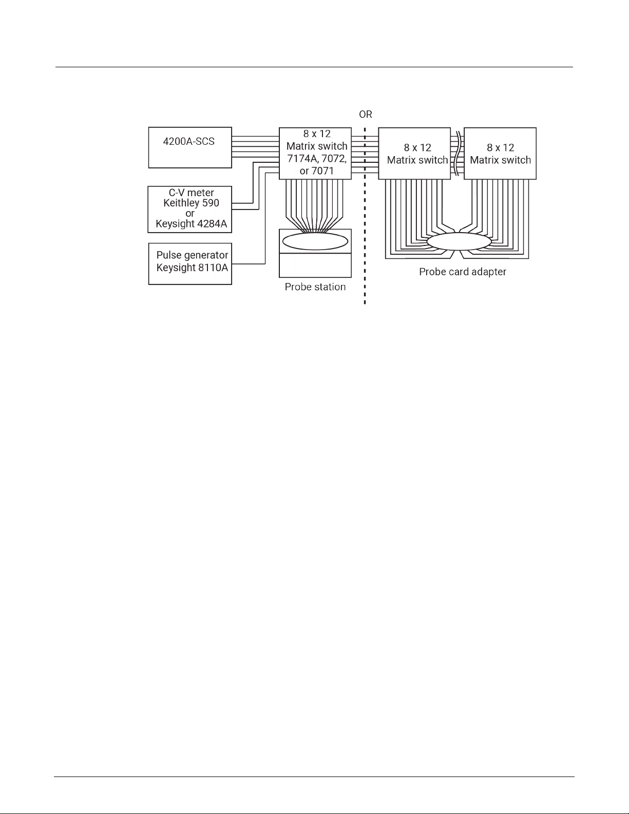
A switch matrix provides automatic switching for test instrumentation and devices under test (DUTs).
Typical switch matrix systems are shown in the following figure.
The 4200A-SCS supports the Keithley Instruments Series 700 Switching System as external
instruments. This series includes the 707, 707A, and 707B, which have six slots for matrix cards. This
provides up to 72 pins of switching. This series also includes the 708, 708A, and 708B, which support
a single matrix card for 12 pins of matrix switching.
When using a switch matrix, one probe station or one test fixture must be present in the system
configuration because the probe station or test fixture establishes the number of test-system pins.
The matrix is cabled to the test system pins, and instrument terminals are routed through the matrix to
the pins using the user modules in the Matrixulib user library.
The following figure shows switch matrix cards connected to a probe station in order to test a wafer.
However, a probe station could be replaced by a test fixture to test discrete devices.
Section 2: Using switch matrices Model 4200A-SCS Prober and External Instrument Control
Figure 1: Typical systems using a switch matrix
Matrix card types
The recommended Keithley Instruments matrix cards are:
• Model 7072 8 x 12 Semiconductor Matrix Card, <1 pA offset current
• Model 7174A 8 x 12 Low Current Matrix Card, <100 fA offset current
Note that a key characteristic of these cards is low offset current to minimize the negative effects of
offset currents on low-current measurements.
7072 Semiconductor Matrix Card
The 7072 provides two two-pole low-current paths that have <1 pA offset current (rows A and B), two
one-pole CV paths for characterization from DC to 1 MHz (rows G and H), and four two-pole paths for
general purpose switching (rows C, D, E, and F). The card is equipped with 3-lug triaxial connectors
for signal connections. The maximum signal level is 200 V, 1 A. The maximum leakage is 0.01 pA/V
and the 3 dB bandwidth is 5 MHz (CV channels).
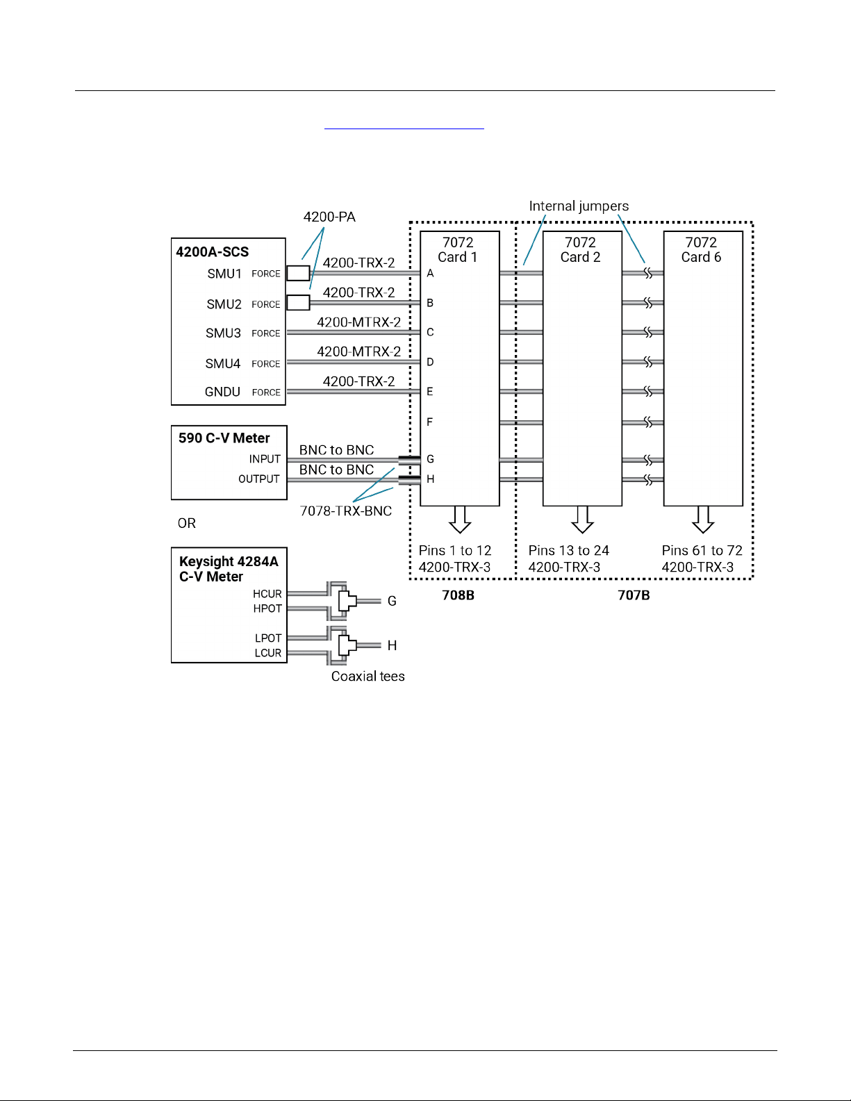
The following figure shows a test system using 7072 matrix cards. The connection requirements for
this card are the same as the connection requirements for the 7174A. Notice that the C-V meter is
connected to rows G and H. These two rows are optimized for C-V measurements.
If using preamplifiers with the 4200A-SCS, they should be connected to the first two rows of the 7072
matrix card.
2-2 4200A-913-01 Rev. B / June 2022
Model 4200A-SCS Prober and External Instrument Control Section 2: Using switch matrices
The following figure and the C-V Analyzer signal pat h s (on page 2-20) figures show how signals are
routed through 7072 matrix switches to a DUT.
Figure 2: Test system using 7072 matrix cards
7174A Low Current Matrix Card
The 7174A provides high quality, high performance switching of I-V and C-V signals. This matrix card
uses 3-pole switching (HI, LO, Guard) with 10 fA typical offset current. The card is equipped with 3lug triaxial connectors for signal connections.
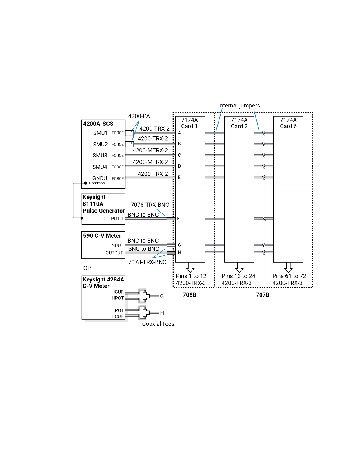
The following figures show test systems using 7174A matrix cards. The supplied triaxial cables
connect the 4200A-SCS directly to matrix rows. The other instruments in the system are fitted with
BNC connectors that require the use of BNC-to-triaxial adapters.
4200A-913-01 Rev. B / June 2022 2-3
Section 2: Using switch matrices Model 4200A-SCS Prober and External Instrument Control
7174A connections for local sensing
The following figure shows a system that uses local sensing. Coaxial tees adapt the Keysight 4284A
C-V meter for two-term in al operat io n.
Figure 3: Test system using 7174A matrix cards
7174A connections for remote sensing
The following figure shows how to connect instrumentation for remote sense operation. Since there
are not enough matrix rows, the instruments are connected to the matrix columns. In this
configuration, two switch relays are closed to complete a path from an instrument to a device under
test (DUT). With five DUT matrix cards installed in a Series 700 Switching System mainframe, up to
30 DUT pin-pairs can be used.
2-4 4200A-913-01 Rev. B / June 2022

Model 4200A-SCS Prober and External Instrument Control Section 2: Using switch matrices
In the following figure, the C-V Analyzer signal paths (on page 2-20) for the Keysight Model 4980A
and Keysight Model 8110A pulse generator signal path (on page 2-23) show how signals are routed
through 7174A matrix switches to a DUT.
In this example, the instrumentation is connected to matrix columns, so the switch matrix is rotated
90° for i
llustration purposes.
Figure 4: Remote sense test system using 7174A matrix cards
4200A-913-01 Rev. B / June 2022 2-5

Section 2: Using switch matrices Model 4200A-SCS Prober and External Instrument Control
Switch matrix mainframes
The 4200A-SCS provides a user library that contains preconfigured data acquisition and control user
modules for the Series 700 Switch System.
You can use the 4200A-SCS with switch matrices from other vendors. However, you will need to
+
develop software to control these matrices from Clarius
Extension Programming (4200A-KULT-907-01) for inf ormation about developing user modules
and libraries.
Card installation
Refer to the instructions for your matrix card for card installation instructions.
GPIB connections
The 4200A-SCS controls the switch matrix using the GPIB interface. Connect the GPIB port of the
switch matrix to the 4200A-SCS using a shielded GPIB cable.
. See Model 4200A-SCS KULT and KULT
Switch matrix connections
A switch matrix enhances the connectivity of the 4200A-SCS by allowing any SMU or preamplifier
signal to be connected to any DUT pin. Typically, devices are connected to columns and instruments
are connected to rows. The following topics summarize recommended switching mainframes and
matrix cards. They also show typical connection schemes with SMUs and preamplifiers.
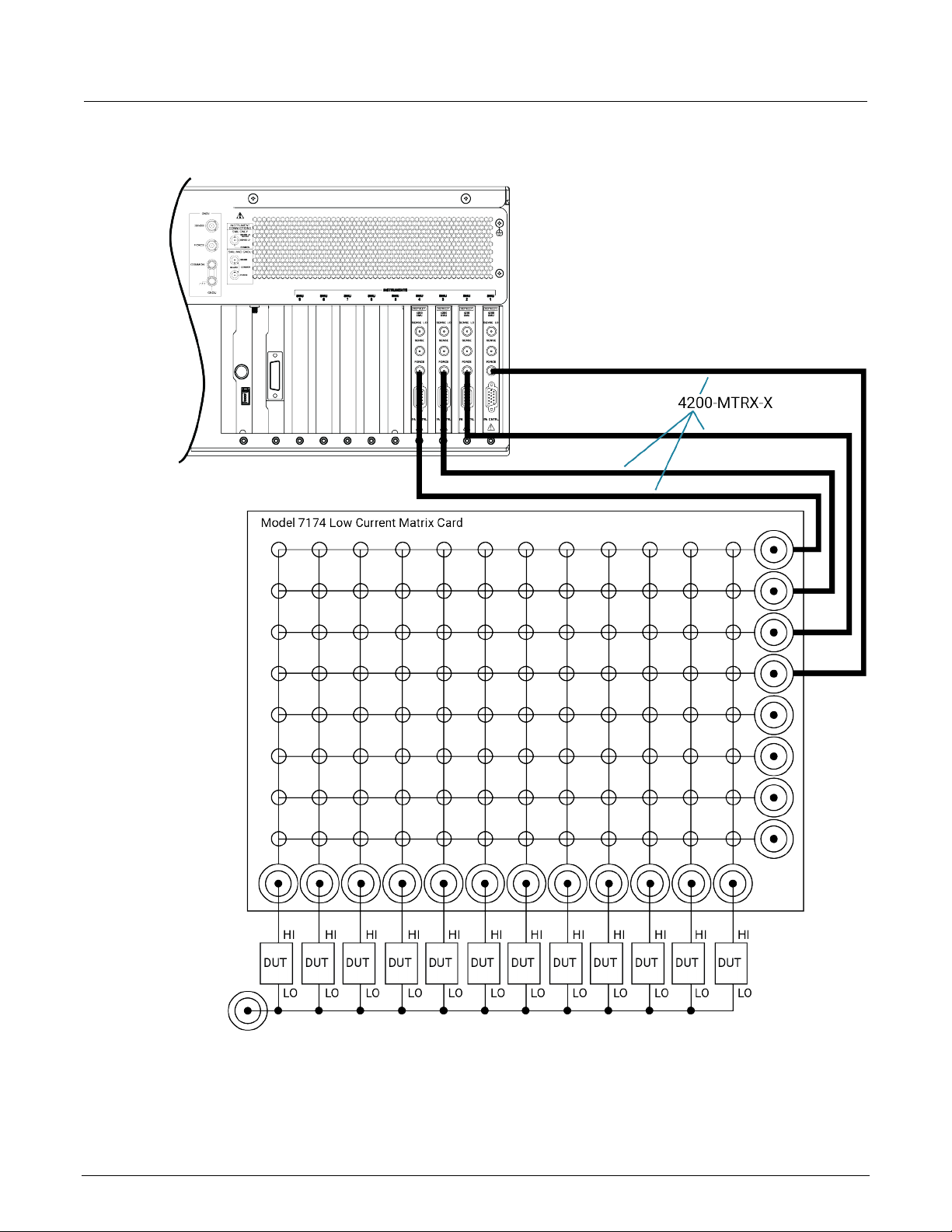
Typical SMU matrix card connections
The following figure shows typical SMU matrix card connections using local sensing. The four SMU
FORCE terminals are connected to the matrix card rows, while the DUT HI terminals are connected to
the matrix card columns. All 12 DUT LO terminals are connected together, and the DUT LO signal is
connected to the ground unit FORCE terminal. Any SMU FORCE terminal can be connected to any
DUT HI terminal simply by closing the appropriate matrix crosspoint.
2-6 4200A-913-01 Rev. B / June 2022
Model 4200A-SCS Prober and External Instrument Control Section 2: Using switch matrices
Figure 5: Typical SMU matrix card connections
4200A-913-01 Rev. B / June 2022 2-7
Section 2: Using switch matrices Model 4200A-SCS Prober and External Instrument Control
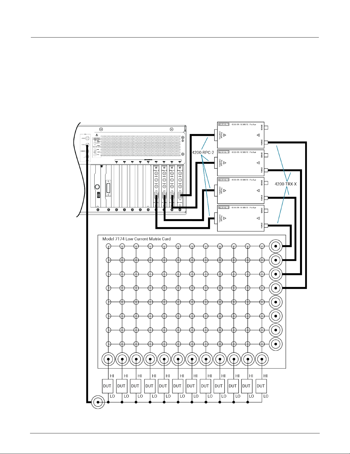
Typical preamplifier matrix card connections
The following figure shows typical preamplifier matrix card connections using local sensing. This
configuration is similar to the SMU configuration shown in the previous figure, except that
preamplifiers are added for low-current source-measure capabilities. The preamplifier FORCE
terminals are connected to the matrix card rows, while the DUT HI terminals are connected to the
matrix card columns. All 12 DUT LO terminals are connected together, and the common DUT LO
signal is connected to the ground unit FORCE terminal. Any preamplifier FORCE terminal can be
connected to any DUT HI terminal by closing the appropriate matrix crosspoint.
Figure 6: Preamplifier matrix card connections
2-8 4200A-913-01 Rev. B / June 2022
Model 4200A-SCS Prober and External Instrument Control Section 2: Using switch matrices
Typical CVU matrix card connections
In your project, you can automate the use of a CVU and other instrumentation using a switching
matrix and actions to control the switching. When the project is run, the switching matrix automatically
makes the required instrument connections for each test in the project.
The next figures show typical connections for a switch system using a Series 700 Switching System
with the 7174A Matrix Card installed.
You can also use the 7072 Matrix Card for C-V t
G and H and local (2-wire) s ensing.
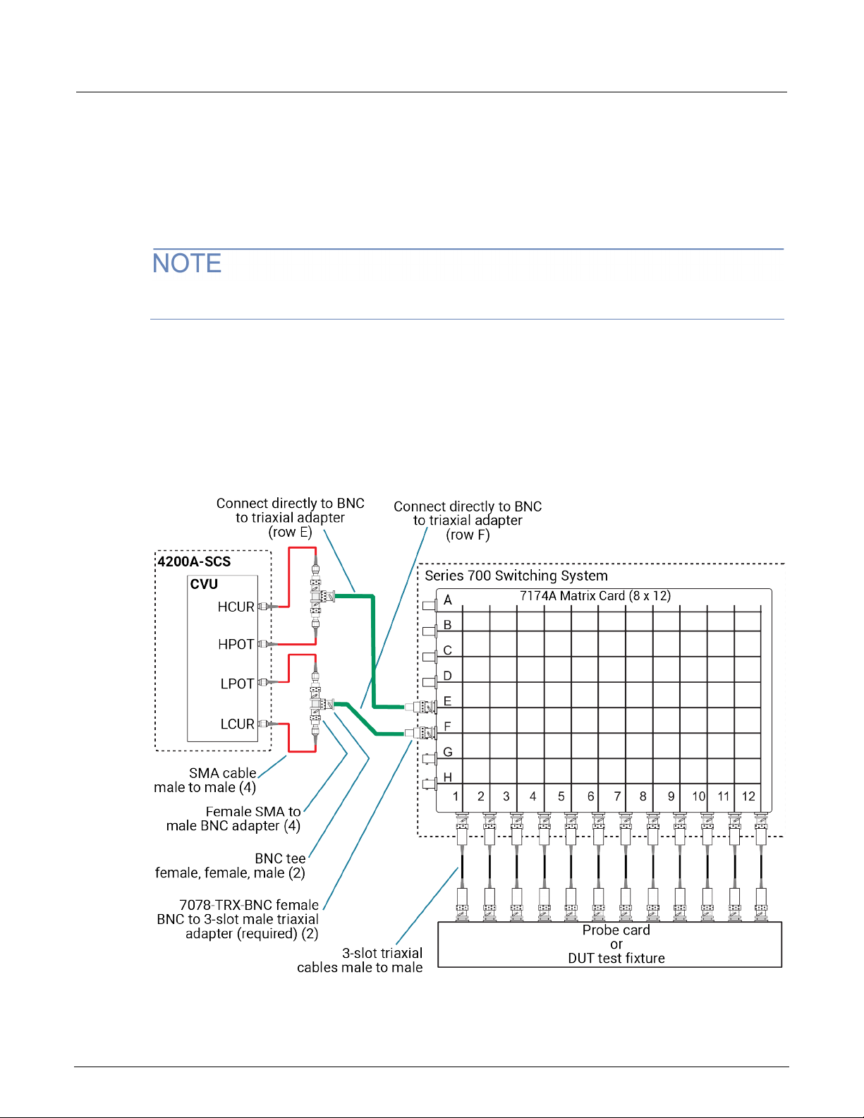
The SMA cables and adapters shown in the following figures are supplied with the CVU or the 4200CVU-PROBER-KIT. The triaxial and BNC cables are not supplied. The prober kit includes two types
of BNC-to-triaxial adapters that connect directly to the rows of the matrix. The 7078-TRX-BNC has the
guard connected to the inner shield of the adapter. The 7078-TRX-GN D has the guard dis connected.
This figure shows connections for local (2-wire) sensing with the CVU connected to rows E and F of
the matrix. This is the connection scheme for the cap-iv-cv-matrix project. For details, see “capiv-cv-matrix” in the Model 4200A-SCS Capacitance-Voltage Unit (CVU) User's Manual.
Figure 7: Test connections for a switch matrix - local (2-wire) sensin g
esting. If you are using the 7072, you must use rows
4200A-913-01 Rev. B / June 2022 2-9

Section 2: Using switch matrices Model 4200A-SCS Prober and External Instrument Control
The following figure shows connections for remote (4-wire) sensing.
Figure 8: Test connections for a switch matrix - remote (4-wire) sensing
The 7078-TRX-BNC adapters must be used in order to extend SMA shielding through the matrix
card.
The shields of the SMA cables must be connected together and extended as far as possible to the
DUT, as shown in Typical CVU test connections to a DUT (on page 2-11).
2-10 4200A-913-01 Rev. B / June 2022
Model 4200A-SCS Prober and External Instrument Control Section 2: Using switch matrices
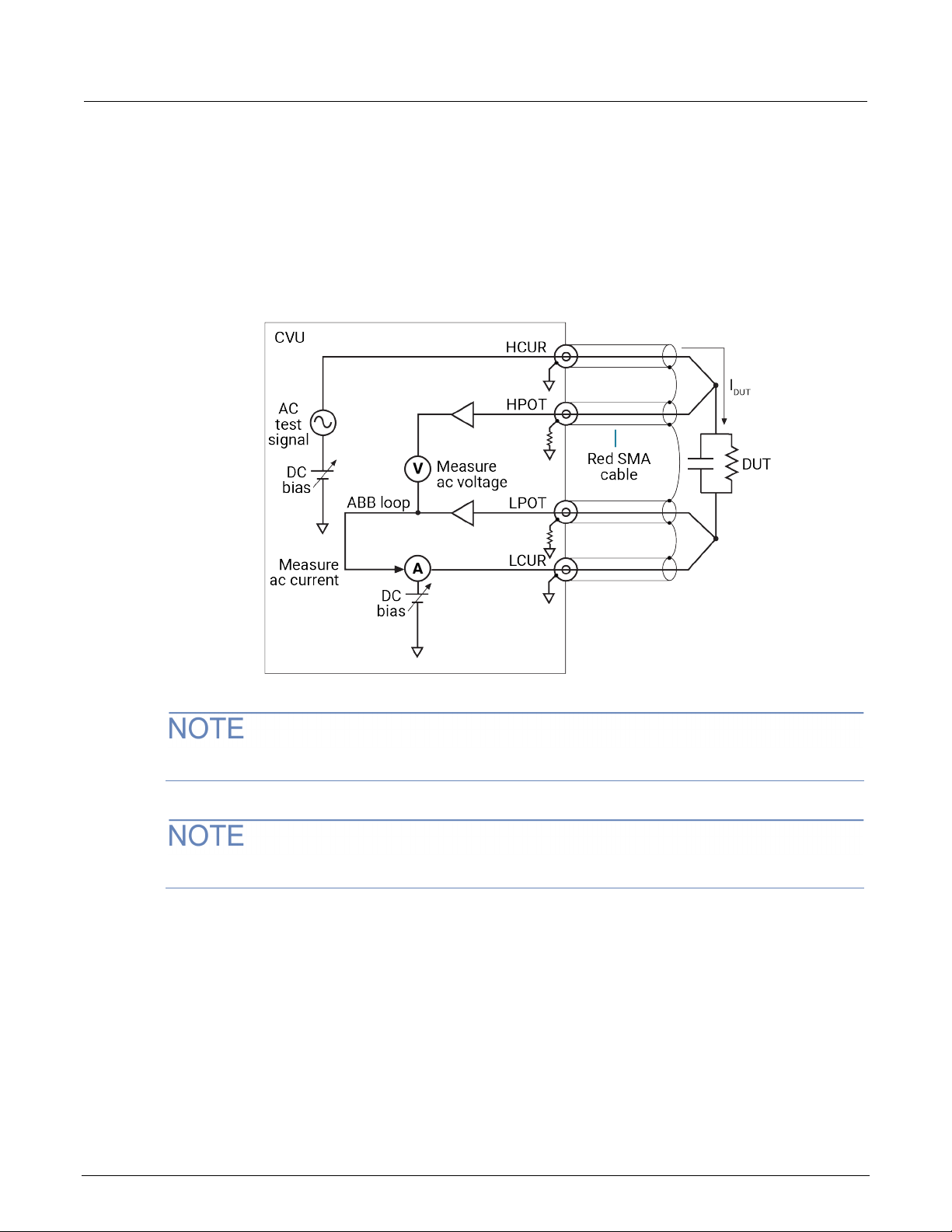
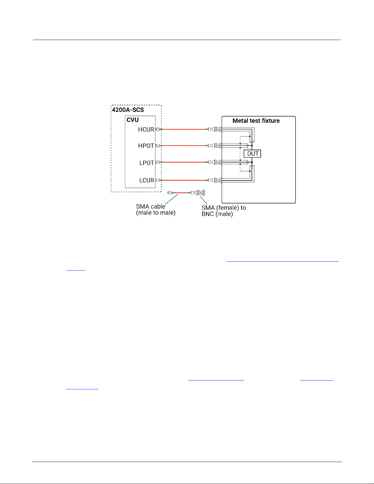
Typical CVU test connections to a DUT
The shields of the SMA cables must be connected together and extended as far as possible to the
device under test (DUT), as shown in the following figure.
Use the supplied torque wrench to tighten the SMA connections to 8 in. lb.
Figure 9: Measurement circuit (simplified)
You can swap the HCUR and HPOT and LCUR and LPOT terminal functionality in Clarius.
The shields of the red SMA cables must be connected together near the DUT.
4200A-913-01 Rev. B / June 2022 2-11
Section 2: Using switch matrices Model 4200A-SCS Prober and External Instrument Control
The following figure shows typical connections to a DUT installed in a test fixture that has BNC
bulkhead connectors. Use a conductive test fixture with the bulkhead connectors mounted directly to
the test fixture. Do not use insulators between the connectors and test fixture. The cables and
adapters shown are the ones supplied with the 4210-CVU or 4215-CVU.
Figure 10: Typical CVU connections to a DUT in a test fixture
Connection scheme settings
The following connection scheme settings are set from the Keithley Configuration Utility (KCon) when
the switch matrix is added to the system configuration. See Using KCon to add a switch matrix to the
system (on page 2-24).
Row-column or instrument card settings
You select the scheme for interconnections between the instruments, the switch-matrix rows and
columns, and the test system (prober or test fixture). You can select:
• Row-Column: Connect instruments to rows and prober or test fixture to columns.
• Instrument Card: Both instruments and prober or test fixture are connect ed to col umns . Matr ix
rows are not used.
The row-column setting is the simplest connection scheme. In this scheme, instruments are
connected to the switch-matrix rows. The prober/test fixture pins or the device under test (DUT) are
connected to the switch-matrix columns (see Switch matrix control (on page 2-16) and
signal paths (on page 2-17)).
4200A-SCS
2-12 4200A-913-01 Rev. B / June 2022
Model 4200A-SCS Prober and External Instrument Control Section 2: Using switch matrices
When you set up a matrix, you also select the sense. You can select:
• Local sense: 2-wire connections. Connections are only to instrument FORCE terminals.
• Remote sense: 4-wire connections. Connections are to both instrument FORCE and SENSE
terminals.
For more information regarding local and remote sense, refer to “Remote sensing” in the Model
4200A-SCS Source -Measure Unit (SMU) User's Manual.
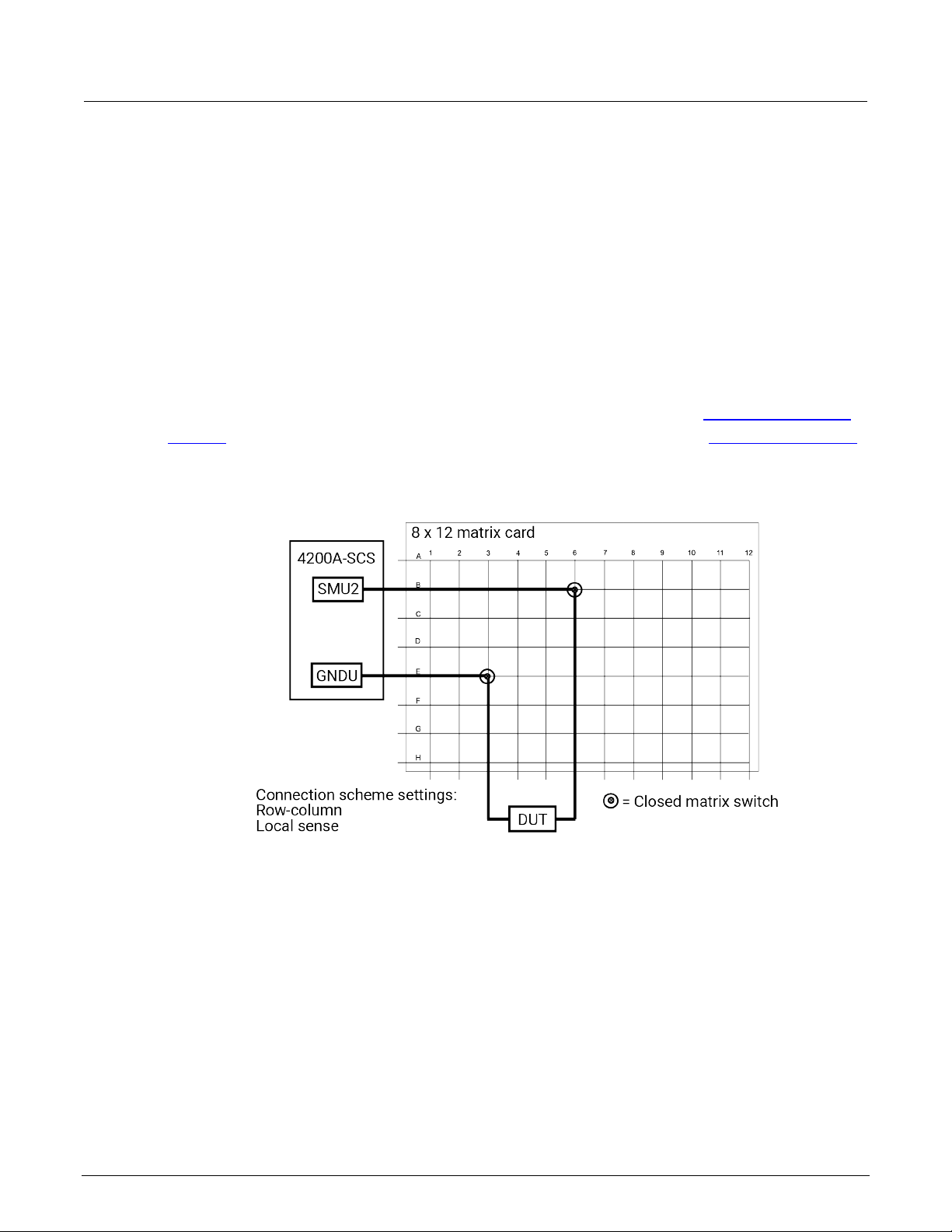
Row-column scheme
The row-column setting is the simplest connection scheme. In this scheme, instruments are
connected to the switch-matrix rows. The prober/test fixture pins or the device under test (DUT) are
connected to the switch-matrix columns (see Switch matrix control (on page 2-16) and 4200A-SCS
signal paths (on page 2-17)).
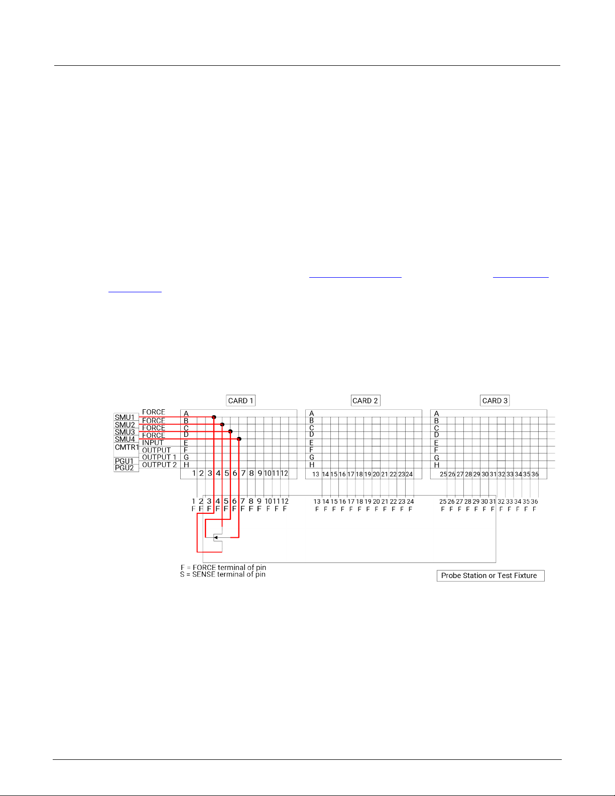
Instrument signals can route to prober/test-fixture pins through only one matrix card, as shown in the
following figure. However, the row-column scheme limits the number of external instruments. If the
instrumentation requirements exceed eight paths (rows), you must use the instrument
card configuration.
Figure 11: Row-Column, Local Sense Connection Scheme example
4200A-913-01 Rev. B / June 2022 2-13
Section 2: Using switch matrices Model 4200A-SCS Prober and External Instrument Control
Instrument card scheme for l ocal sense
Use local sense when the measurement-pathway resistance is small and the associated voltage
errors are negligible. The measurement pathway is comprised of the following conductors, connected
in series:
• The cables used to connect the instruments to the matrix
• The internal matrix-card signal path
• The cables used to connect the matrix to the prober or test fixture
Current flowing through the measurement pathway creates a voltage drop (an error voltage) that is
directly proportional to the pathway resistance. This error voltage is present in all local sense voltage
measurements.
When local sense is selected, only the connection paths specified by the connected action are
completed. For example, in the figure in Switch matrix control (on page 2-16
connection paths would be:
• SMU2, 6 (connect SMU2 to Pin 6)
• GNDU, 3 (connect GNDU to Pin 3)
), the specified
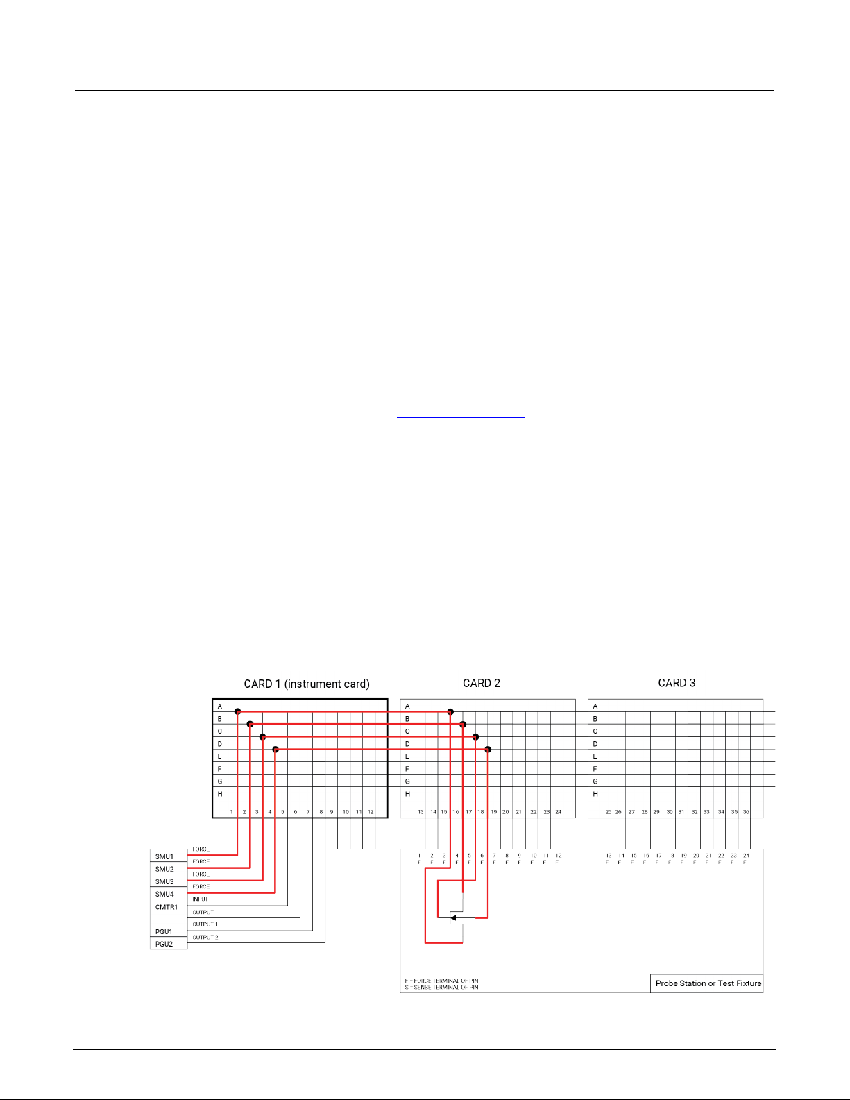
For the instrument card scheme, both the instrumentation and the prober/text-fixture pins or DUT are
connected to switch-matrix columns. No external conn ec tions ar e made to matr ix r ows . In this
configuration, two switch relays are closed to complete a path from an instrument to a DUT.
Instrument signals route to the prober/test-fixture pins through two or more matrix cards, as shown in
the following figure. This connection scheme can support large systems with numerous instruments
by removing the eight-row instrument connection limitation.
Figure 12: Instrument Card, Local Sense Connection Scheme example
2-14 4200A-913-01 Rev. B / June 2022
Model 4200A-SCS Prober and External Instrument Control Section 2: Using switch matrices
Row A paired with row B
Column 1 paired with Column 2
Row C paired with row D
Column 3 paired with Column 4
Row E paired with row F
Column 5 paired with Column 6
Row G paired with row H
Column 7 paired with Column 8
Column 9 paired with Column 10
Column 11 paired with Column 12
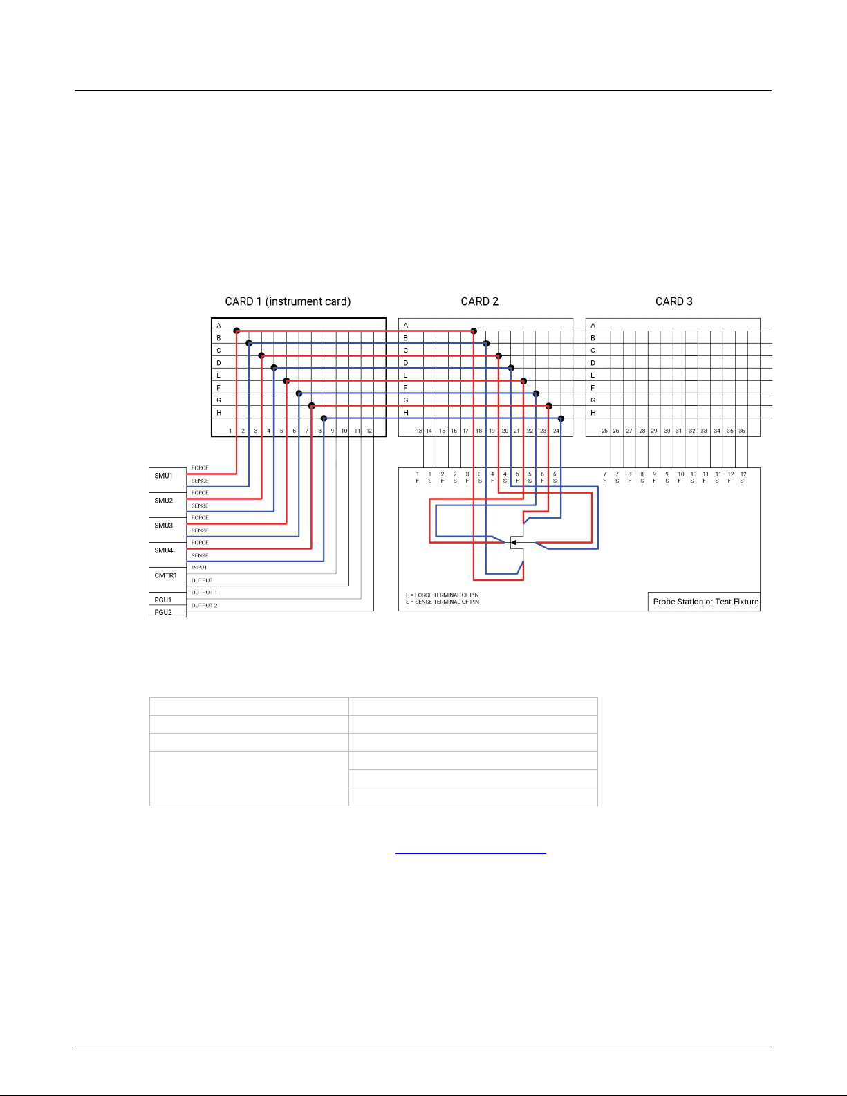
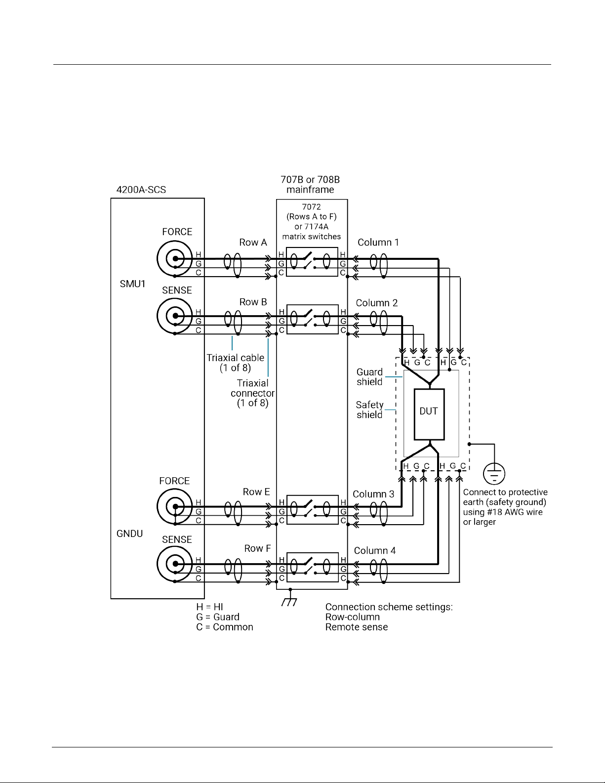
Instrument card scheme for remote sense
Use remote sense to eliminate the effects of measurement pathway resistance. The following figure
illustrates the use of remote sense in an instrument card configuration. Note that remote sense
requires twice as many measurement pathways. The FORCE pathways (in red) are the currentcarrying pathways, and the SENSE pathways (in blue) are the meas urem ent path way s .
Figure 13: Instrument Card, Rem o te Sense Connection Scheme example
When remote sense is selected, rows and columns are paired together as shown in the following
table.
When you specify a connection path in the connect action, the paired connection path is also
completed. For example, in the figure in 4200A-SCS signal paths ( on pag e 2-17), the specified
connection paths would be:
• SMU1, 4 (connect SMU1 to Pin 4)
• GNDU, 3 (connect GNDU to Pin 3)
4200A-913-01 Rev. B / June 2022 2-15
Section 2: Using switch matrices Model 4200A-SCS Prober and External Instrument Control
Switch matrix control
To control switching, you can use the connect action in the ivcvswitch project. You can also use
the ConnectPins user module in the Matrixulib user library.
The connect action uses the ConnectPins user module to control a switch matrix. You specify t
i
nstrument terminal and pin pairs. For example, for the row-column connection scheme shown in the
following figure, you set the parameters:
he
• TermIDStr2 to SMU2 and Pin2 to 6, which connects SMU2 to pin 6.
• TermIDStr8 to GNDU and Pin8 to 3, which connects GNDU (ground unit) to pin 3.
A matrix control example using the ConnectPins user module is provided in Switch matrix control
example (on page 2-31). Detailed information for ConnectPins is provided in Matrixulib user library
(on page 2-33).
Figure 14: Row-column connection scheme
Signal paths to a DUT
The following figures show signal path examples from the various test instruments through the matrix
switches to a DUT.
2-16 4200A-913-01 Rev. B / June 2022
Model 4200A-SCS Prober and External Instrument Control Section 2: Using switch matrices
4200A-SCS signal paths
The following figure shows remote sensing (4-wire) signal paths through a matrix card using two-pole
switching. Two-pole switching is provided by the 7174A and 7072 (rows A through F).
Figure 15: 4200A-SCS signal paths through a two-pole matrix card using remote sensing
4200A-913-01 Rev. B / June 2022 2-17
Section 2: Using switch matrices Model 4200A-SCS Prober and External Instrument Control
Row A (force) paired with row B (sense)
Column 1 (force) paired with column 2 (sense)
Row E (force) paired with row F (sense)
Column 3 (force) paired with column 4 (sense)
Sense setting
To make the connections shown in 4200A-SCS signal paths (on page 2-17), you must select remote
sensing.
When remote sensing is selected, the rows and columns are paired together as follows:
When the FORCE matrix switches are closed by the ConnectPins user module, the SENSE matrix
switches are also closed.
For local sensing (2-wire), the connections from the SENSE terminals of the 4200A-SC S ar e
not used.
For more information regarding local and remote sense, refer to “Remote sensing” in the Mode
4200A-SCS Source -Measure Unit (SMU) User's Manual.
Connection setting
The row-column setting must be used when connecting instrumentation to matrix rows, as shown in
4200A-SCS signal paths (on page 2-17).
The maximum number of rows available to the test system is eight. If instrumentation needs more
than eight pathways, they must be connected to matrix columns, and the instrument card setting must
be used.
The following figure shows a test system with both the instruments and the DUT connected to
matrix columns.
See Connection scheme settings (on page 2-12
settings. The connection scheme settings shown in this figure are Instrument Card and
Remote Sense.
) for details on the row-col
umn and instrument card
l
2-18 4200A-913-01 Rev. B / June 2022

Model 4200A-SCS Prober and External Instrument Control Section 2: Using switch matrices
Figure 16: Instrument card connection scheme
The 4200A-SCS automatically selects the first available rows to make connections to the DUT. In
this example, rows A through D are the first available rows.
The following shows 4200A-SCS signal paths through a 3-pole 7071 matrix card using remote
sensing. Note that for this configuration, each FORCE and SENSE connector does not use a
separate path (row). Unlike the configuration shown in 4200A-SCS signal paths (on page 2-17), each
FORCE/SENSE connector pair is routed through a single 3-pole matrix switch. Since row pairing is
not required, the local sense setting must be used.
For two-wire local sense connections, do not use the SENSE connectors of the 4200A-SCS
.
To avoid high voltage exposure that could result in personal injury or death, whenever the
inte
rlock of the 4200A-SCS is asserted, the FORCE and GUARD term inals of the SMUs and
preamplifier should be considered to be at high voltage, even if they are programmed to a
nonhazardous voltage current.
4200A-913-01 Rev. B / June 2022 2-19

Section 2: Using switch matrices Model 4200A-SCS Prober and External Instrument Control
Figure 17: 4200A-SCS signal paths through a 3-pole matrix card using remote sensing
C-V Analyzer signal paths
The following figures show local sense C-V Analyzer signal paths through rows B and H of a 7072
matrix card. A C-V analyzer can be used with any of the three matrix card types; however, rows G
and H of the 7072 are optimized for C-V measurements.
2-20 4200A-913-01 Rev. B / June 2022

Model 4200A-SCS Prober and External Instrument Control Section 2: Using switch matrices
Figure 18: 590 signal paths through 7072 matrix card using local sensing
Figure 19: Keysight Model 4980A signal paths through 7072 matrix card using local sensing
4200A-913-01 Rev. B / June 2022 2-21

Section 2: Using switch matrices Model 4200A-SCS Prober and External Instrument Control
The following figure shows the remote sense signal paths for the Keysight Model 4980A LCR meter
through a 2-pole matrix card. Since row pairing is required, the remote sense setting must be used.
Figure 20: Keysight Model 4980A signal paths through a two-pole matrix card using remote
sensing
2-22 4200A-913-01 Rev. B / June 2022

Model 4200A-SCS Prober and External Instrument Control Section 2: Using switch matrices
Keysight Model 8110A pulse generator signal path
The following figure shows the HI signal path through the 7174A matrix card. However, the pulse
generator can also be used with other matrix card types.
Note that the pulse generator LO is not routed through the matrix card. A separate external return
path is required. The chassis of the pulse generator is output LO. As shown in the following figure,
use a banana plug cable that is terminated with a spade lug on one end. Connect the banana plug
end of the cable to the Common banana jack of the GNDU, and attach the spade lug end to a chassis
screw on the pulse generator.
Figure 21: Keysight Model 8110A signal path through a 7174A matrix card
4200A-913-01 Rev. B / June 2022 2-23

Section 2: Using switch matrices Model 4200A-SCS Prober and External Instrument Control
Use KCon to add a sw itch matrix to the system
You use Keithley Configuration Utility (KCon) to manage the configuration of all instr umen tat ion
controlled by the 4200A-SCS software. To use the 4200A-SCS to control a switch matrix, you must
add the switch matrix to the system configuration using KCon.
If you are testing discrete device under test (DUTs), you must use the switch matrix with a test fixture.
If you are testing a wafer, you must use the switch matrix with a probe station. The test fixture or
probe station is also added to the system configuration using KCon.
You specify physical instrument-to-card and card-to-prober or fixture connections in KCon.
These and other KCon switch matrix settings result in simplified matrix connections. Initially, you
need to:
• Add the test fixture or probe station.
• Configure the Instrument Connection Scheme and Switch Cards areas.
• Specify the physical instrument-to-card and card-to-prober/fixture connections.
• Physically make the specified instrument-to-card and card-to-prober/fixture connections.
After the initial setup, you can specify instrument-to-prober/fixture connections by specifying the
corresponding terminal and prober/fixture pins in a Clarius user test module (UTM). You do not need
to specify matrix cross points. The 4200A-SCS automatically routes the signals through the matrix.
For additional detail on KCon, refer to the Model 4200A-SCS Setup and Maintenance User's Manual.
If you are using a 707B or 708B Switching System, you must use the control panel on the front of
y
our switching system to enable DDC and change the command set to 70XB by following these
steps:
1. Select Menu.
2. Select DDC.
3. Select Enable.
4. Select 70XB-VERSION.
This allows the switching system to be controlled by the 4200A-SCS.
Step 1. Exit Clarius and open KCon
To exit Clarius and open KCon:
1. Exit Clarius.
2. On the Windows desktop, select the KCon icon.
2-24 4200A-913-01 Rev. B / June 2022

Model 4200A-SCS Prober and External Instrument Control Section 2: Using switch matrices
Step 2. Add a test fixture or probe station
You must use a test fixture or a probe station with the switch matrix. However, both cannot be in the
system configuration together. If you need to remove a component, refer to “Remove an external
instrument” in Model 4200A-SCS Paramet er Analy zer Setu p and Mai nte nanc e .
Add a test fixture
To add a test fixture to the system configuration:
1. Select Add External Instrument
2. S
elect Test Fixture.
3. Select OK.
4. In the System Configuration list, select the test fixture (prefix is TF).
.
Figure 22: Add test fixture
5. From the Model list, select the appropriate test fixture.
6. Enter the number of pins. You can enter 2 to 72 pins.
The number of pins defined in the test fixture properties determines the pins that are available to
ign to a switch matrix card column. Make sure the number of pins assigned is appropriate for
ass
your system.
4200A-913-01 Rev. B / June 2022 2-25

Section 2: Using switch matrices Model 4200A-SCS Prober and External Instrument Control
Add a probe station
Supported probe stations include:
• Fake Prober
• Manual Prober
• Micromanipulator 8860 Prober
• Cascade Microtech PA200 Prober
• Cascade Summit-12000 Pr ober
• Signatone CM500 (WL250) Prober
• MPI TS2000, TS2000-D P, TS2 0 00-HP, TS2000-SE, TS3000, and TS3000-SE Pr obe rs
Contact Keithley for the most up-to-date list of supported probers. If you are using an unsupported
prober, you must create a user library and module to control it.
To add a probe station to the system configura tion:
1. Select Add External Instrument
2. S
elect Probe Station.
3. Select OK.
4. In the System Configuration list, select the probe station. The Properties are displayed.
.
Figure 23: Probe station properties
2-26 4200A-913-01 Rev. B / June 2022

Model 4200A-SCS Prober and External Instrument Control Section 2: Using switch matrices
5. From the Model list, select the prober.
6. Enter the Number of Pins / Positioners.
7. Select the options that are appropriate for your prober.
The number of pins defined in the probe station properties determines the pins that are available to
assign to a switch matrix card column. Make sure the number of pins assigned is appropriate for
your system.
Step 3. Add switching system mainframe
The default GPIB address for the Series 700B Switching systems is 16.
To add a switching system mainframe:
1. Select Add External Instrument
2. S
elect the Keithley 707/707A/707B Switching Matrix or Keithley 708/708A/708B Switching
Matrix.
3. Select OK.
4. In the System Configuration list, select the switching matrix. The properties are displayed. T
ollowing figure shows the properties for the 707/707A/707B. If the 708/708A/708B mainframe is
f
selected, there is only one switch card slot.
.
he
4200A-913-01 Rev. B / June 2022 2-27

Section 2: Using switch matrices Model 4200A-SCS Prober and External Instrument Control
Figure 24: KCon MTRX1 Properties
Step 4. Set GPIB address
The GPIB address setting in the properties must match the actual GPIB address of the mainframe.
The address for the switch system mainframe is briefly displayed during its power-on sequence.
To set the GPIB address:
1. Select the GPIB Address from the list. Addresses that are in use are displayed with asterisks (*)
next to them. The range of addresses is 0 to 30 (GPIB address 31 is reserved as the 4200A-SCS
c
ontroller address). If the selected GPIB address conflicts with the GPIB address of another
system component, a red exclamation-point symbol (!) is displayed next to the selected address.
2. Select Save to save the change.
You can programmatically read the GPIB address and other instrument properties from the system
conf
iguration using the LPT library getinstattr function. Proper use of getinstattr allows y
o develop user libraries that are independent of the configuration. For more information, refer to
t
Model 4200A-SCS KULT and KULT Extension Pr ogra mmi ng (4200A-KULT-907-01).
ou
2-28 4200A-913-01 Rev. B / June 2022

Model 4200A-SCS Prober and External Instrument Control Section 2: Using switch matrices
Step 5. Configure the instrument connection scheme
To configure the instrument connection scheme:
1. Select the Connection Scheme from the list:
If you are connecting the instrumentation to matrix rows and the device under test (DUT) t
matrix columns, select Row-Column.
If all connections (instrumentation and DUT) are made to matrix columns only, select
Instrument Card.
2. Select Local Sense or Remote Sense:
For 2-wire connections to the DUT, select Local Sense.
For 4-wire connections to the DUT, select Remot e Se nse.
Step 6. Assign switch cards to mainframe slots
To assign switch cards to mainframe slots:
1. For each slot that contains a matrix card, select the model number of the matrix card.
2. For each slot that is empty, select Empty.
You cannot mix matrix card models. For example, if you set slot 1 to Keithley 7174 Low Current
Matrix Card, all other slots can only be set to the 7174 or Empty. To select a different model, you
must set all slots to Empty and then make the new selection.
o
Figure 25: Assign switch cards to slots
4200A-913-01 Rev. B / June 2022 2-29

Section 2: Using switch matrices Model 4200A-SCS Prober and External Instrument Control
Step 7. Set matrix card properties
The matrix card properties set the connections:
• Between the measurement instrumentation and the matrix card
• Between the matrix card and the test system (prober or test fixture)
The number of pins defined in the properties for a probe station or test fixture determines the pins
that are available to assign to a switch matrix card column. Make sure the number of pins assigned
is appropriate for your system. Refer to Add a test fixture (on pag e 2-25) or Add a probe station (on
page 2-26) for additional information.
To set matrix card properties:
1. In the System Configuration list, expand the switching matrix.
2. Select the card. The properties are displayed. Each row and column has a list to set the card
properties. If the row-column connection scheme is selected, instruments are assigned to t
ows and the test fixture pins or probe pins are assigned to the columns. If the instrument car
r
c
onnection scheme is selected, both instrumentation and test fixture/probe pins are assigned t
olumns.
c
he
d
o
The following figure shows the 7071 Matrix Card Properties settings that are required to support
the physical connections that are shown in Row-column or instrument card settings (on page
12).
3. Select from the lists to connect the rows and columns to instrument terminals and prober or test
fixture pins. Note that card properties must match the actual physical connections to th
mat
rix card.
In the following figure, the lists labeled A to H correspond to the eight rows of the Keithley
Instruments matrix cards that are compatible with the Series 700 Switching System. The lists
labeled 1 to 12 correspond to the 12 columns of these matrix cards.
4. Select Validate.
Prober or test-fixture pins are always connected to matrix-card columns.
2-
e
2-30 4200A-913-01 Rev. B / June 2022

Model 4200A-SCS Prober and External Instrument Control Section 2: Using switch matrices
Figure 26: Keithley 7071 Matrix Card Properties
Step 8. Save configuration
To save the KCon configuration:
1. Select Save.
Step 9. Close KCon and open Clarius
To close KCon and open Clarius:
1. To close KCon, select the close button in the upper right.
2. On the Windows desktop, select the Clarius icon.
Switch matrix control example
This example demonstrates how the connectpins action controls a switch matrix. You modify the
connectpins action to connect SMU2 to a DUT, as shown in the Switch matrix control (on page 2-
16) figure. It assumes that the switch matrix is set for row-column connections with local sense
selected. It also assumes that the matrix card properties are set as shown in Switch matrix control.
The connectpins action is based on the ConnectPins user module. Detail on ConnectPins is
provided in Matrixulib user library (on page 2-33).
4200A-913-01 Rev. B / June 2022 2-31

Section 2: Using switch matrices Model 4200A-SCS Prober and External Instrument Control
Set up and run a switch matrix in Clarius
To set up and run the connectpins action:
1. Choose Select.
2. Select Actions.
3. Search for connectpins.
4. Select the connectpins action.
5. Select Add.
6. In the project tree, select the connectpins action.
7. Select Configure. The parameter settings are displayed, as shown in the following figure.
Figure 27: connectpins settings
8. Set Pin2 to 6. This connects SMU2 to point 6.
9. Select OpenAll to open all matrix card switches.
10. Set Pin5 to 3. This connects GNDU to pin 5.
11. Leave all other pin settings at 0 to indicate that no connection will be made.
12. Select Run. The 4200A-SCS connects to the DUT.
2-32 4200A-913-01 Rev. B / June 2022

Model 4200A-SCS Prober and External Instrument Control Section 2: Using switch matrices
ConnectPins
Allows you to control your switch matrix.
status
Returned values; see Details
OpenAll
Controls if the switch matrix is cleared before making any new connections:
Leave previous connections intact: 0
TermIdStr1
Terminal identification string; refers to an instrument as defined by TermIdStr8 in
Pin1
The DUT pin number (configuration dependent) to which the instrument will be
Matrixulib u ser library
The Matrixulib connects instrument terminals to output pins using a Keithley Instruments Series
700 Switching System. It is for use with switching systems that are configured as a general purpose,
low current, or ultra-low current matrix.
Matrixulib user module
User module Description
ConnectPins user module
The ConnectPins module allows you to control your switch matrix.
Usage
status = ConnectPins(int OpenAll, char *TermIdStr1, int Pin1, char *TermIdStr2, int
Pin2, char *TermIdStr3, int Pin3, char *TermIdStr4, int Pin4, char *TermIdStr5,
int Pin5, char *TermIdStr6, int Pin6, char *TermIdStr7, int Pin7, char
*TermIdStr8, int Pin8);
TermIdStr2
TermIdStr3
TermIdStr4
TermIdStr5
TermIdStr6
TermIdStr7
TermIdStr8
Pin2
Pin3
Pin4
Pin5
Pin6
Pin7
Pin8
Clear all previous connections: 1
KCon; valid inputs (configuration dependent) are: SMUn, CMTRn, CMTRnL, PGUn,
GPIn, GPInL, GNDU (where n is a number from 1 through 8)
attached; if a number less than 1 is specified, no connection is made; valid inputs:
−1 to 72
4200A-913-01 Rev. B / June 2022 2-33

Section 2: Using switch matrices Model 4200A-SCS Prober and External Instrument Control
Details
This user module allows you to control a switch matrix. The default input parameters are shown in the
following figure. Typically, OpenAll (line 1) is set to 1 to initially open all connections. If set to 0, the
present connections are not affected.
The rest of the input parameters are structured as terminal/pin pairs. Each terminal/pin pair specifies
the signal path through the matrix. For example, if the specified pin parameter for SMU1 is 4, then
SMU4 will connect to pin 4 of the test fixture or prober when the UTM is run. The pin parameter value
0 (or −1) indicates that no connection will be made.
Terminal ID: Terminal identification for the most common components used in the system
configuration are as follows:
• SMU1 to SMU4: These are the signal HI terminals for the four SMUs.
• GNDU: This is common terminal for the Ground Unit of the 4200A-SCS.
• CMTR1: This is used for a C-V Analyzer. For the 590, it is the OUTPUT terminal. For the
K
eysight Model 4980A, it is the HCUR terminal.
• CMTR1L: This is also used for a C-V Analyzer. For the 590, it is the INPUT terminal. For the
K
eysight Model 4980A, it is the LCUR terminal.
• PGU1: This is output HI for the Keysight Model 8110A Pulse Generator.
A test example demonstrates how this user module controls the switch matrix (see Switc h matrix
control example (on page 2-31)).
Figure 28: connectpins settings
2-34 4200A-913-01 Rev. B / June 2022

Model 4200A-SCS Prober and External Instrument Control Section 2: Using switch matrices
To connect SMU1 to pin 7, SMU2 to pin 8, SMU3 to pin 12, SMU4 to pin 1, ground pin 15, connect the
ConnectPins(1, SMU1, 7, SMU2, 8, SMU3, 12, SMU4, 1, GNDU, 15 PGU1, 13, CMTR1,
9, CMTR1L, 10)
You can connect the instrument terminals to one or more DUT pins. If the DUT pin number is less
than 1, then that connection is ignored (not performed), otherwise the specified instrument is
connected to the desired DUT pin. If you wish to connect an instrument to more than one DUT pin,
you may specify that instrument terminal again in the parameter list.
If the OpenAll parameter is less than one, then the matrix is not cleared before making connections;
if OpenAll is 1, then all previous matrix connections are cleared before making the new connections.
Returned values are placed in the Analyze sheet and can be:
• 0 OK.
• -10000 (INVAL_INST_ID): The specified instrument ID does not exist. This generally means
that there is no instrument with the specif ied ID in your configuration.
• -10001 (INVAL_PIN_SPEC): An invalid DUT pin number was specified.
• -10003 (NO_SWITCH_MATRIX): No switch matrix was found.
• -10004 (NO_MATRIX_CARDS): No matrix cards were found.
Example
Also see
pulse generator to pin 13, connect the CMTR to pins 9 and 10, and clear the previous connections:
None
4200A-913-01 Rev. B / June 2022 2-35

Set up the measurements in Clarius .........................................3-9
Configure and use a Series 700 Switchi ng System
In this section:
Introduction ...............................................................................3-1
Equipment required ...................................................................3-2
Device connections ...................................................................3-2
Update the switch configuration in KCon ..................................3-5
Introduction
This section describes how to configure a Keithley Instruments Series 700 Switching System (707,
707A, 707B, 708, 708A, or 708B) in the Keithley Configuration Utility (KCon). You can then use the
system to connect any instrument terminal to any test system pin without changing connections. You
can also create a new project for an n-channel MOSFET transistor and use the project to make both
I-V and C-V measurements using the switching system.
Section 3
Switching systems are controlled by the 4200A-SCS using the GPIB bus. Use a shielded GPIB cable
to connect your switching system to the 4200A-SCS. Once the switching system and test fixture have
been defined in KCon, you use Clarius to set up the connections and automatically connect the
instruments to the test system pins using the switching system.
In Clarius, the connectpins action from the Action Library is used to control switching systems. This
action controls the opening and closing of crosspoints in a switching system so that you can connect
any row of the matrix card to any (or multiple) columns of the matrix card. The connectpins action
is added to the project and runs twice in this example. Each run establishes new connection settings.

Section 3: Configure and use a Series 700 Switching System Model 4200A-SCS Prober and External Instrument Control
Equipment required
• One 4200A-SCS with the following instruments:
Three 4200-SMUs, 420 1-SMUs, 4210-SMUs, or 4211-SMUs
One 4210-CVU or 4215-CVU
• Eight 4200-MTRX-X triaxial cables or 4200-TRX-X cables if using preamplifiers
• Four CA-447A SMA cables (supplied with the CVU)
• Four CS-1247 SMA female to BNC male adapters (supplied with the CVU)
• Two CS-701A BNC Tee adapters (female, male, female)
• Two 7078-TRX-BNC BNC female to triaxial male adapters
• One Series 700 Switching System with a 7072 8x12 Matrix Card
• One shielded four-terminal test fixture with triaxial inputs
• One n-channel MOSFET transistor
Device connections
The next topics detail the connections from the 7072 to the n-channel MOSFET and the connections
from the SMUs or CVU, and GNDU to the 7072 Matrix Card in the Series 700 Switching System.
Hazardous voltages may be present on all output and guard
shock that could cause injury or death, never connect or disconnect from the instrument
while the output is on.
To prevent electric shock, test connections must be configured such that the user cannot
come in contact with test leads, conductors, or any device under test (DUT) that is in contact
with the conductors. It is good practice to disconnect DUTs from the instrument before
powering up the instrument. Safe installation requires proper shields, barriers, and g rounding
to prevent contact with test lead and con du ctors.
terminals. To prevent electrical
3-2 4200A-913-01 Rev. B / June 2022

Model 4200A-SCS Prober and External Instrument Control Section 3: Configure and use a Series 700 Switching System
Connect the 7072 to the DUT
The hardware connections from the 7072 Matrix Card to the 4-term in al MOSF ET DUT are shown in
the following figure. Use four triaxial cables to connect to the input terminals of your test fixture. For
systems without a preamplifier, use 4200-MTRX-X triaxial cables. For system with preamplifiers, use
4200-TRX-X triaxial cables.
Figure 29: Connections from the 7072 Matrix Card to the MOSFET DUT
4200A-913-01 Rev. B / June 2022 3-3

Section 3: Configure and use a Series 700 Switching System Model 4200A-SCS Prober and External Instrument Control
Connect the 4200A-SCS to the 7072
This section describes connections to the 7072.
To connect the 4200A-SCS and SMUs to the 7072:
Using four 4200-MTRX-X or 4200-TRX-X triaxial cables, make the following connections:
• 4200A-SCS GNDU FORCE to 7072 input terminal E
• 42x0 SMU channel 1 Force to 7072 input terminal A
• 42x0 SMU channel 2 Force to 7072 input terminal B
• 42x0 SMU channel 3 Force to 7072 input terminal C
To connect the 4210-CVU or 4215-CVU to the 7072:
1. Using the parts in the following figure, assemble a tee adapter to connect the CVU to the 7072.
Figure 30: 4210-CVU to 7072 adapter tee assembly
2. Using four CA-447A SMA cables, make the following connections:
CVU HCUR to adapter tee assembly 1
CVU HPOT to adapter tee assembly 1
CVU LPOT to adapter tee ass embly 2
CVU LCUR to adapter tee assembly 2
3. Connect adapter tee assembly 1 to input terminal G of the 7072.
4. Connect adapter tee assembly 2 to input terminal H of the 7072.
The connections are shown in the following figure.
3-4 4200A-913-01 Rev. B / June 2022

Model 4200A-SCS Prober and External Instrument Control Section 3: Configure and use a Series 700 Switching System
Figure 31: 4200A-SCS to 7072 Matrix Card connections
Update the switch configuration in KCon
After completing the switch and device connections, use KCon to manage the configuration of all
instrumentation controlled by the 4200A-SCS software. You use KCon to:
• Add the switching system to the 4200A-SCS configuration
• Add the test fixture to the system configuration
• Configure the test fixture
• Add a matrix card to the switching system
• Configure the matrix card connections
4200A-913-01 Rev. B / June 2022 3-5

Section 3: Configure and use a Series 700 Switching System Model 4200A-SCS Prober and External Instrument Control
If you are using a 707B or 708B Switching System, you must use the control panel on the front of
your switching system to enable DDC and change the command set to 70XB by following
these steps:
1. Select Menu.
2. Select DDC.
3. Select Enable.
4. Select 70XB-VERSION.
This allows the switching system to be controlled by the 4200A-SCS.
To add a switching system to the 4200A-SCS configur ation:
1. From the desktop, open the KCon application.
2. In the bottom left of the KCon window, select Add External Instrument.
3. Select your switching system. The Series 700 Switching Systems are highlighted in the followin
f
igure.
Figure 32: Add External Instrument b ox, Series 700 Switching Systems highlighted
g
3-6 4200A-913-01 Rev. B / June 2022

Model 4200A-SCS Prober and External Instrument Control Section 3: Configure and use a Series 700 Switching System
4. Select OK.
5. Select Add External Instrument again.
6. Select Test Fixture.
Figure 33: Add External Instrument d ialog box, Test Fixture highlighted
7. Select OK.
8. From the System Configuration list, select the test fixture you just added (TF1).
9. Set the number of pins equal to the number of output pins in your switching system (12 for this
example, using one 7072 matrix card).
10. From the System Configuration list, select the switching system you just added (MTRX1).
11. In the Properties pane, add the 7072 Matrix Card to the correct slot of the switching system.
12. Confirm that the GPIB Channel of your device (0 to 30) matches the channel shown in th
roperties.
P
e
13. Open MTRX1 in the System Configuration list.
14. Select CARD1. The Properties for the 7072 Matrix Card are displayed, as shown in the following
figure.
4200A-913-01 Rev. B / June 2022 3-7

Section 3: Configure and use a Series 700 Switching System Model 4200A-SCS Prober and External Instrument Control
15. Complete the Card Rows Assignments according to how you connected the instruments to the
. For this example, the assignments are:
7072
Row A - SMU1 Force
Row B - SMU2 Force
Row C - SMU3 Force
Row E - GNDU Force
Row G - CVU1 CVH_CUR
Row H - CVU1 CVL_CUR
16. Under Card Columns Assignment, designate at least the first four columns with pin assignments
that match their column number. For example, Pin 1 Force to column 1.
Figure 34: Completed Properties pane for the 7072 Matrix Card
17. From the KCon toolbar, select Validate to ensure that the switching system is connected
operly.
pr
18. Select Save to save the system configuration.
19. Select Summary, then scroll down to the Connections section. You need the names from t
T
erminal ID column when setting the switching system connections in Clarius. You can select
he
Save Configuration As or Print Configuration to record the terminal IDs. The default values for
the most common instruments are shown in the following figure.
3-8 4200A-913-01 Rev. B / June 2022

Model 4200A-SCS Prober and External Instrument Control Section 3: Configure and use a Series 700 Switching System
Figure 35: Summary: Default Terminal ID connections
20. Close the window when you are finished.
21. Close the KCon application.
Set up the measurements in Clarius
After closing KCon, open the Clarius application from the desktop. In this section, you use the Clarius
application to configure and run two tests on an n-channel MOSFET transistor: A plot of drain current
versus drain voltage using the SMUs and a C-V sweep. By using the Series 700 Switching System,
you do not need to rearrange cables between the tests.
For this example, you use the Clarius application to:
• Create a new project
• Add a device
• Add an action
• Configure the action
• Search for and add two tests
• Run the project and view the tests
4200A-913-01 Rev. B / June 2022 3-9

Section 3: Configure and use a Series 700 Switching System Model 4200A-SCS Prober and External Instrument Control
Create a new project
To create a new project:
1. Choose Select.
2. In the Library, select Projects.
3. Select New Project.
4. Select Create.
Figure 36: Create new project
5. Select Yes when prompted to replace the existing project.
Add a device
To add a device:
1. Select Devices.
2. Enter MOSFET in the search box.
3. Select Search.
4. Scroll to the MOSFET, n-type, 4 terminal (4terminal-n-fet) device.
5. Select Add to add it to the project tree.
3-10 4200A-913-01 Rev. B / June 2022

Model 4200A-SCS Prober and External Instrument Control Section 3: Configure and use a Series 700 Switching System
Add the connectpins action
To add the connectpins action:
1. Select Actions.
2. Type connect in the search box.
3. Select Search.
4. Scroll to the connectpins action, then Add it to the project tree twice.
Figure 37: connectpins added twice
Configure the connectpins action
To configure the connectpins action:
1. Select the first connectpins action you added to the project tree.
2. Select Configure.
Figure 38: Configure highlighte d
4200A-913-01 Rev. B / June 2022 3-11

Section 3: Configure and use a Series 700 Switching System Model 4200A-SCS Prober and External Instrument Control
3. Make the following connections using the pairs of TermIdStr# and Pin# fields in the action:
SMU1 – Pin 3
SMU2 – Pin 2
SMU3 – Pin 1
GNDU – Pin 4
When you are finished, the Key Parameters view of the action should look like the next graphic.
The order of the instruments does not matter if each instrument is paired with the correct
pin number.
In this example, assigning TermIdStr1 to SMU1 and Pin 1 to 3 connects SMU1 to Pin 3 on
the matrix.
Figure 39: connectpins device connections
If the OpenAll checkbox is selected, the connectpins action opens all crosspoints before closing
the specified pairs. This is the default and is usually the preferred behavior. However, since
connectpins only has eight field pairs, the action can only close eight crosspoints during each run.
To close more crosspoints, use multiple connectpins actions.
4. Select Save.
5. Select the second connectpins action you added to the project tree.
3-12 4200A-913-01 Rev. B / June 2022

Model 4200A-SCS Prober and External Instrument Control Section 3: Configure and use a Series 700 Switching System
6. Make the following connections using the pairs of TermIdStr# and Pin# text fields in the action:
CVH1 – Pin 1
CVL1 – Pin 2
CVL1 – Pin 3
CVL1 – Pin 4
When you are finished, the Key Parameters for the action look like the following figure.
Figure 40: Second connectpins co nn ections
7. Select Save.
Search for and add existing tests from the Test Library
To search for and add existing tests from the Test Library:
1. Choose Select.
2. Select Tests.
3. Type vds into the search box.
4. Select Search.
5. Scroll to the vds-id test.
6. Select Add to add it to the project tree.
7. Drag the vds-id test to between the two connectpins actions.
8. Clear the search box.
9. Type cv into the search box.
10. Select Search.
4200A-913-01 Rev. B / June 2022 3-13

Section 3: Configure and use a Series 700 Switching System Model 4200A-SCS Prober and External Instrument Control
11. Scroll to the cv-nmosfet test. Select Add to add it to the project tree.
12. Drag the cv-nmosfet test after the second connectpins action.
Your project tree looks like the following fig ur e.
Figure 41: Project tree showing tests and actions in the proper order
Run the project and view the tests
To run the project and view the tests:
1. In the project tree, select New Project.
2. Make sure the items in the project tree are checked.
3. Select Run to start the test. The actions and tests run sequentially. The connectpins actions
set the crosspoints before the tests are executed.
You can select Analyze when you run the project to view test results in real time.
Figure 42: Analyze highlighted
To view the results of a test either as it runs or after it has completed, select the test in the
project tree.
3-14 4200A-913-01 Rev. B / June 2022

KI590ulib user library ..............................................................4-12
In this section:
Introduction ...............................................................................4-1
C-V measurement basics ..........................................................4-1
Capacitance measurement tes ts ...............................................4-2
Connections ..............................................................................4-2
Cable compensation .................................................................4-4
Using KCon to add a 590 C-V Analy zer to sys tem ....................4-5
Model 590 test examples ..........................................................4-5
Introduction
Section 4
Using a Model 590 C-V An alyzer
This section describes how to set up and use a Model 590 C-V Analyzer with the 4200A-SCS.
For details on 590 operation, refer to the Model 590 C-V Analyzer Instruction Manual (document
number 590-901-01), available at tek.com/keithley
C-V measurement basics
The Keithley Instruments Model 590 C-V Analyzer measures capacitance versus voltage (C-V) and
capacitance versus time (C-t) of semiconductor devices. Typically, C-V measurements are made on
capacitor-like devices, such as a metal-oxide-silicon capacitor (MOS capacitor).
The measurements of MOS capacitors study:
• The integrity of the gate oxide and semiconductor doping profile
• The lifetime of semiconductor material
• The interface quality between the gate oxide and silicon
• Other dielectric materials used in an integrated circuit
The voltage sweeping capability of the 590 makes it easy to make a series of capacitance
measurements that span the three regions of a C-V curve: the accumulation region, depletion region,
and inversion region.
.

Section 4: Using a Model 590 C-V Analyzer Model 4200A-SCS Prober and External Instrument Control
The following figure shows the three regions of a typical C-V curve for a MOS capacitor.
Figure 43: Typical C-V curve for a MOS capacitor
Capacitance measurement tests
The 4200A-SCS provides the following tests to perform C-V tests using the 590:
• 590 C-V Sweep (590-cvsweep): Makes a capacitance measurement at each step of a user-
configured linear voltage sweep.
• 590 C-V Pulse Sweep (590-cvpulsesweep): Makes a capacitance measurement at each step of
a user-configured pulsed voltage sweep.
• 590 C-t Sweep (590-ctsweep): Makes a specified number of capacitance measurements at a
s
pecified time interval. Voltage is held constant for these capacitance measurements.
• 590 Capacitance Measurements (590-cmeas): Makes capacitance and conductance
urements at a fixed bias voltage.
meas
There are also user modules available for the 590. Refer to KI590ulib user library (on page 4-12).
Connections
This section describes basic BNC, triaxial, and GPIB connections. For additional information about
590 connections, see the Model 590 C-V Analyzer Instruction Manual (document number
590-901-01), available at tek.com/keithley.
4-2 4200A-913-01 Rev. B / June 2022

Model 4200A-SCS Prober and External Instrument Control Section 4: Using a Model 590 C-V Analyzer
Signal connections
Basic signal connections for the 590 are shown in the following figure.
The center conductors of the BNC connectors are connected to the device under test (DUT). The
outer shield of one of the coaxial cables is typically connected to a Faraday shield. The Model 590
output is typically connected to the wafer backside (or well). The input is typically connected to the
gate of a MOS capacitor.
Figure 44: Basic 590 connections to the DUT
Triaxial connectors
Adapters are required to connect the 590 to equipment (for example, a probe station, test fixture, or
matrix card) that uses triaxial connectors. The 7078-TRX-BNC is a 3-lug triaxial to BNC adapter. As
shown in the following figure, connect the adapters to the 3-slot triaxial connectors and then use a
7051 BNC cable to make the connections to the 590.
See Using Switch Matrices (on page 2-1
Analyzer.
Figure 45: Connecting the 590 to equi pment with triaxial connectors
) for details on using a switch matrix with the 590 C-V
4200A-913-01 Rev. B / June 2022 4-3

Section 4: Using a Model 590 C-V Analyzer Model 4200A-SCS Prober and External Instrument Control
2 pF
0.5 pF
1.5 pF
20 pF
4.7 pF
18 pF
200 pF
47 pF
180 pF
2 nF
470 pF
1.8 nF
The following figure shows the equivalent circuit for the adapter.
Figure 46: 7078-TRX-BNC equivalent circuit
GPIB connections
The 4200A-SCS controls the 590 through the General Purpose Interface Bus (GPIB). Use a shielded
GPIB cable to connect the GPIB of the 590 to the GPIB of the 4200A-SCS.
Cable compensat ion
Signal pathways through the test cables, switch matrix, test fixture, and prober contribute unwanted
capacitances that may adversely affect the measurement.
To correct for these unwanted capacitances, you should do cable compensation before measuring
the capacitance of DUT. In general, you do cable compensation by connecting precisely known
capacitance sources in place of the DUT and then measuring them. The 590 then uses these
measured values to make corrections when measuring the DUT.
During cable compensation:
1. The 590 calculates the compensation parameters based on the comparison between the giv
measured values.
and
en
2. The 590 makes a probe-up offset measurement and suppresses any remaining offset
capacitance. This step is done every time a new measurement is made.
Typically, cable compensation is done for all measurement ranges (2 pF, 20 pF, 200 pF, and 2 nF) of
the 590. Once cable compensation is done, it does not have to be done again unless the connections
to the DUT are changed or power is cycled.
For each measurement range of the 590, you must use a low-capacitance source and a highcapacitance source. The following table lists the Keithley Instruments Model 5909 capacitance
sources that can be used for each 590 range.
5909 capacitance sources
590 range Low capacitance source High capacitance source
4-4 4200A-913-01 Rev. B / June 2022

Model 4200A-SCS Prober and External Instrument Control Section 4: Using a Model 590 C-V Analyzer
Cable compensation user modules
The 4200A-SCS KI590ulib user library includes the following user modules for
cable compensation:
• SaveCableCompCaps590: Enter and save capacitance source values: The user enters the
ac
tual capacitance values of the capacitance sources. When the test is executed, t
capacitance values are stored in a file at a user-specified directory path.
• DisplayCableCompCaps590: Places capacitance values into the Analyze spreadsheet:
When this test is executed, the capacitance values saved by SaveCableCompCaps82 ar
aced into the Analyze spreadsheet.
pl
• CableCompensate590: Performs cable compensation: The user specifies the ranges and test
frequencies for cable compensation. When this test is executed, on-screen prompts guide you
through the cable compensation process.
• LoadCableCorrectionConstants: This function reads the cable compensation parameters for
the range and frequency specified from the cable compensation file and sends these parameters
to the 590.
he
e
Details on all user modules for the 590 are provided in KI590ulib user library (on page 4-12).
Using KCon to add a 590 C-V Analyzer to system
To use the 4200A-SCS to control an external instrument, that instrument must be added to the
system configuration. The 590 C-V Analyzer is added to the test system using the Keithley
Configuration Utility (KCon).
Refer to “Use KCon to add equipment to the 4200A-SCS” in Model 4200A-SCS Parameter Analy zer
Setup and Maintenance for instruction.
Model 590 test examp les
The test examples for the Model 590 C-V Analyzer are controlled by user test modules (UTMs) in the
ivcvswitch project. The following figure shows the tree for the project.
A switch matrix is not used for these examples.
4200A-913-01 Rev. B / June 2022 4-5

Section 4: Using a Model 590 C-V Analyzer Model 4200A-SCS Prober and External Instrument Control
Cable compensation example
This example assumes that the 590 is connected directly to the DUT. The DUT could be a device
installed in a test fixture or a MOS capacitor on a wafer.
The user modules for cable compensation must share the same file for capacitance source values.
efore, the same file directory path must be used in all three user modules. For this example, use
Ther
the default file directory path (see line 1 of the parameter list in the following figures).
Enter an d save capa citance source values (save-cap-file)
To enter and save the capacitance source values:
1. Select Configure.
2. In the project tree, select save-cap-file. The default parameters for the user module ar
di
splayed, as shown in the following figure.
Figure 47: save-cap-file action and SaveCableCompCaps590 user module
3. Enter the capacitance source calibration value for each range and frequency. If you are using the
5909
, each capacitor has a label indicating the calibration value at 100 kHz and at 1 MHz.
e
For example, assume the low capacitance source for the 2 pF range is 0.47773 pF (100 kHz) and
0.47786 pF (1 MHz). Enter these values using scientific notation:
Lo2p100k: Enter 0.47773e-12
Lo2p1M: Enter 0.47786e-12
4. In the project tree, select the action.
5. Click Run to execute the action.
4-6 4200A-913-01 Rev. B / June 2022

Model 4200A-SCS Prober and External Instrument Control Section 4: Using a Model 590 C-V Analyzer
Place capacitance source values in a spreadsheet (display-cap-file)
To place the source values in the Analyze sheet:
1. Select display-cap-file. The default parameters are displayed, as shown in the following figure.
Figure 48: DisplayCableCompCaps590 default parameters
2. Ensure that the CabCompFile field has the same file directory path that is used in save-cap-
file (Enter and save capacitance source values (save-cap-file) (on pag e 4-6)).
3. Set the array size in the RangeSize, Values100kSize, and Values1MSize fields.
4. Click Run. The calibration source values are placed into the Analyze sheet for this action.
5. Select Analyze to view the spreadsheet for display-cap-file. An example spreadsheet is
shown in the following figure.
Figure 49: Display-cap-file spreadsheet showing capacitor source values
4200A-913-01 Rev. B / June 2022 4-7

Section 4: Using a Model 590 C-V Analyzer Model 4200A-SCS Prober and External Instrument Control
Perform cable compensation (CableCompensat e )
To do cable compensation:
1. Select Configure.
2. In the project tree, select cable-compensate to open the action. The following figure shows th
default parameters for the action.
Figure 50: CableCompensate590 default parameters
e
3. Ensure that CabCompFile has the same file directory path that is used in save-cap-file
(Enter and save capacitance source values (SaveCableCompCaps590) (on page 4-6)).
4. Enable or disable cable compensation. The FreqN and RangeN parameters either disable (0) or
enable (1) cable compensation for the frequencies and ranges. The figure above shows cable
compensation enabled for all ranges and test frequencies.
4-8 4200A-913-01 Rev. B / June 2022

Model 4200A-SCS Prober and External Instrument Control Section 4: Using a Model 590 C-V Analyzer
5. Click Run to execute the action. A series of dialog boxes guides you through the cable
ompensation process. The basic dialog boxes are shown in the following figure:
c
Raise the probes: This dialog box indicates that an offset (open circuit) measurement is
required. Open the circuit as close to the DUT as possible.
Connect the capacitor: The value in the dialog box corresponds to a calibration value entere
by the user in Enter and save capacitance source values (on page 4-6
). Connect t
he
capacitance source as close to the DUT as possible.
Compare readings: This dialog box compares the measured value to the calibration (nominal)
alue entered by the user. The two readings should be fairly close. If they are not, y
v
pr
obably connected the wrong capacitance source or had an open circuit condition. In that
ou
case, click Cancel to abort the cable compensation process.
Clicking Cancel in a cable compensation dialog box aborts the cable compensation process. You
can start over by clicking Run.
Figure 51: Cable compensation dialog boxes
d
4200A-913-01 Rev. B / June 2022 4-9

Section 4: Using a Model 590 C-V Analyzer Model 4200A-SCS Prober and External Instrument Control
C-V sweep example
This example demonstrates how to control a Keithley Instruments 590 C-V Analyzer to acquire
capacitance verses voltage (CV) data from a MOS capacitor. In this example, the C-V Analyzer
applies a linear staircase voltage sweep to a capacitor. A capacitance measurement is made on
every voltage step of the sweep.
This example assumes that the 590 is connected directly to the DUT. The DUT could be a device
installed in a test fixture or a MOS capacitor on a wafer.
To do a C-V sweep:
1. Choose Select.
2. Select Tests.
3. Search for 590.
4. Select Add for the 590 C-V Sweep (590-cvsweep) test.
5. In the project tree, select 590-cvsweep.
6. Select Configure. The parameters are displayed.
Figure 52: CvSweep590 user module (590-cvsweep UTM)
7. Change the test parameters as needed.
8. Execute the test by clicking Run.
This test uses the CvSweep590 user module. For details on this test description, see CvSweep590
user module (on page 4-26).
4-10 4200A-913-01 Rev. B / June 2022

Model 4200A-SCS Prober and External Instrument Control Section 4: Using a Model 590 C-V Analyzer
If you use the default parameters, this test causes the 590 to do a −4 V to +6 V staircase sweep using
50 mV steps. The following figure shows the default sweep.
Figure 53: C-V linear staircase sweep
4200A-913-01 Rev. B / June 2022 4-11

Section 4: Using a Model 590 C-V Analyzer Model 4200A-SCS Prober and External Instrument Control
CableCompensate590
in
ivcvswitch
Cmeas590
590-cmeas
Makes a single capacitance
measurement.
CtSweep590
590-ctsweep
Makes a capacitance versus time
measurement.
CvPulseSweep590
590-cvpulsesweep
Makes capacitance versus voltage
measurements using a pulse sweep.
CvSweep590
590-cvsweep
Makes capacitance versus voltage
measurements using a staircase sweep.
DisplayCableCompCaps590
in
ivcvswitch
Places capacitance source values in a
LoadCableCorrectionConstants
n/a
Reads the cable compensation
and sends these parameters to the 590.
SaveCableCompCaps590
in the
ivcvswitch
status
Returned values; see Details
CabCompFile
The complete name and path for the cable compensat ion file ; see Details
InstIdStr
The CMTR instrument ID; CMTR1, CMTR2, CMTR3, or CMTR4, depending on your
system configuration
InputPin
The DUT pin to which the 590 input terminal is attached (−1 to 72); if a value of less
than 1 is specified, no switch matrix connection is made; see Details
OutPin
The DUT pin to which the 590 output terminal is attached (−1 to 72); if a value of
less than 1 is specified, no switch matrix connection is ma de; see Details
KI590ulib user l ibrary
The user modules in the KI590ulib user library are used to control the 590 C-V Analyzer. These
user modules are summarized in the following table. Also listed in the table are names of the user test
modules (UTMs) and actions in Clarius that use the user modules.
KI590ulib user modules
User module UTM or action name Description
cable-compensate
the
display-cap-file
the
project
project
Performs cable compens atio n usin g
known capacitance source values.
spreadsheet.
parameters for the range and frequency
specified from the cable compensation file
save-cap-file
project
Saves entered capacitance source values
to a file.
CableCompensate590 user module
The CableCompensate590 routine performs the 590 cable compensation procedure using the capacitor values
that are stored in the specified cable compensation file. The resultant compensation values generated by the
compensation process are stored in the same file.
Usage
status = CableCompensate590(char *CabCompFile, char *InstIdStr, int InputPin, int
OutPin, int Freq100k, int Freq1M, int Range2p, int Range20p, int Range200p, int
range2n);
4-12 4200A-913-01 Rev. B / June 2022

Model 4200A-SCS Prober and External Instrument Control Section 4: Using a Model 590 C-V Analyzer
Freq100k
Determines if compensation is done for the 100 kHz frequency:
Compensate: 1
Freq1M
Determines if compensation is done for the 1 MHz frequ en cy :
1
Range2p
Determines if compensation is done for the 2 pF range:
1
Range20p
Determines if compensation is done for the 20 pF range:
Compensate: 1
Range200p
Determines if compensation is done for the 200 pF range:
1
range2n
Compensate: 1
Do not compensate: 0
Do not compensate: 0
Compensate:
Do not compensate: 0
Compensate:
Do not compensate: 0
Do not compensate: 0
Compensate:
Determines if compensation is done for the 2 nF range:
Do not compensate: 0
Details
This user module performs cable compensation for the selected ranges and test frequencies of the
590.The following figure shows the default input parameters for a UTM that uses t
CableCompensate590
If the default parameters are used, cable compensation is done for the 2 pF, 20 pF, 200 pF, and 2 nF
ranges and for the 100 kHz and 1 MHz test frequencies. The line 1 input parameter indicates the
directory path where the user-input capacitor source values are saved. These values are entered and
saved using the SaveCableCompCaps590 user module.
user module.
Figure 54: CableCompensate590 default parameters
he
Test example 1 demonstrates how to do cable compensation (see Model 590 test examples
page 4-5)).
4200A-913-01 Rev. B / June 2022 4-13
(on

Section 4: Using a Model 590 C-V Analyzer Model 4200A-SCS Prober and External Instrument Control
If the file defined for CabCompFile does not exist, or there is no path specified (null string), the
default compensation para meters are used. Wh en entering the path, use two backslash (\\
c
haracters to separate each directory. For example, if your cable file is in
C:\calfiles\590cal.dat, you enter the following:
C:\\calfiles\\590cal.dat
If a switch matrix to route signals is being controlled by a connection action (for example, connect),
t
here is no need to connect InputPin and OutPin. Set these parameters to 0.
Returned values are placed in the Analyze sheet.
)
• 0: OK.
• -10000 (INVAL_INST_ID): The specified instrument ID does not exist
• -10021 (COMP_FILE_NOT_EXIST): The specified compensation file does not exist
• -10022 (KI590_NOT_IN_KCON): There is no CMTR defined in your system configuration.
Procedure
Also see
For each range and test frequency specified by the input parameters:
1. You are prompted to open the circuit so that an offset capacitance measurement can be made.
2. When the offset capacitance measurement is completed, you are prompted to connect the low
value capacitor for the selected range. The system does the low value capacitor compensation.
3. You are prompted to connect the high value capacitor for the selected range. The system does
the high value capacitor compensation.
4. You are prompted to reconnect the low capacitor.
5. The nominal and measured values are displayed in a dialog box. You can:
Select Cancel to abort the procedure if the results are not correct. No changes to the cabl
ompensation file occur.
c
Select Save to save the cable compensation values.
None
e
4-14 4200A-913-01 Rev. B / June 2022

Model 4200A-SCS Prober and External Instrument Control Section 4: Using a Model 590 C-V Analyzer
status
Returned values; see Details
CabCompFile
The complete name and path for the cable compensat ion file ; see Details
InstIdStr
The CMTR instrument ID; CMTR1, CMTR2, CMTR3, or CMTR4, depending on your
system configuration
InputPin
than 1 is specified, no switch matrix connection is made; see Details
OutPin
OffsetCorrect
Determines if an offset correction meas urem ent sho uld be m ade:
1
Frequency
The measurement frequency to use:
1
DefaultBias
StartTime
The amount of time to delay after applying the DefaultBias voltage step
(0.001 s to 65 s)
Range
The measurement range to use: 1 to 4; see Details
Model
Measurement model:
1
Filter
Enables or disables the analog filter:
measurement time): 1
ReadingRate
The reading rate used to acquire the measurements (0 to 4); see Details
C
Output: The measured capacitance
V
Output: The bias voltage used
G_or_R
Output:
Cmeas590 user module
The Cmeas590 routine measures capacitance and conductance using the Keithley Instruments 590 C-V Analyzer.
You can make an offset correction measurement and use cable compensation.
Usage
status = Cmeas590(char *CabCompFile, char *InstIdStr, int InputPin, int OutPin, int
OffsetCorrect, int Frequency, double DefaultBias, double StartTime, double
Range, int Model, int Filter, int ReadingRate, double *C, double *V, double
*G_or_R);
The DUT pin to which the 590 input terminal is attached (−1 to 72); if a value of less
The DUT pin to which the 590 output terminal is attached (−1 to 72); if a value of
less than 1 is specified, no switch matrix connect ion is ma de; see Details
Do not make offset measurement: 0
Make offset measurement:
100 kHz: 0
1 MHz:
The DC bias to use for the measurement: −20 to +20 V
Series model: 0
Parallel model:
Disable: 0
Enable (can minimize the amount noise in the readings, but increases
Parallel measurement model: G_or_R is the measured conductance
Series measurement model: G_or_R is the measured resistance
4200A-913-01 Rev. B / June 2022 4-15

Section 4: Using a Model 590 C-V Analyzer Model 4200A-SCS Prober and External Instrument Control
Details
This user module makes a single, fixed-bias capacitance and conductance measurement. The default
parameters for the 590-cmeas UTM, which uses the Cmeas590 user module, are shown in the
following figure.
Figure 55: Cmeas590 (cmeas UTM parameters)
In general, the 590 is set to source 5 V for 2 seconds, then make a measurement, as shown in the
following figure.
Figure 56: Cmeas590 measurement
If the file defined for CabCompFile does not exist, or there is no path specified (null string), the
default compensation para meters are used. Wh en entering the path, use two backslash (\\
c
haracters to separate each directory. For example, if your cable file is in
)
C:\calfiles\590cal.dat, you enter the following:
C:\\calfiles\\590cal.dat
If a switch matrix to route signals is being controlled by a connection action (for example, connect),
t
here is no need to connect InputPin and OutPin. Set these parameters to 0.
4-16 4200A-913-01 Rev. B / June 2022

Model 4200A-SCS Prober and External Instrument Control Section 4: Using a Model 590 C-V Analyzer
1
2 pF / 2 μs
20 pF / 200 μs
2
20 pF / 20 μs
20 pF / 200 μs
3
200 pF / 200 μs
200 pF / 2 ms
4
2 nF / 2 ms
2 nF / 20 ms
0
1000
C
3.5 1 75
C,G,V
3.5 2 18
C,G,V
4.5
3
10
C,G,V
4.5 4 1
C,G,V
4.5
For Range, the measurement range values are shown in the following table.
Range 100 kHz 1 MHz
The reading rates and resolutions for the ReadingRate parameter are described in the following
table.
Reading rate Nominal reading rate
(per second)
Display readings Resolution
(digits)
Returned values are placed in the Analyze sheet:
• 0: OK.
• -10000 (INVAL_INST_ID): The specified instrument ID does not exist.
• -10020 (COMP_FILE_ACCESS_ERR): There was an error accessing the specified cable
compensation file.
• -10021 (COMP_FILE_NOT_EXIST): The specified compensation file does not exist.
• -10022 (KI590_NOT_IN_KCON): There is no CMTR defined in your system configuration.
• -10023 (KI590_MEAS_ERROR): A measurement error occurred.
• -10090 (GPIB_ERROR_OCCURRED): A GPIB communications error occurred.
Procedure
Also see
4200A-913-01 Rev. B / June 2022 4-17
• -10091 (GPIB_TIMEOUT): A timeout occurred during communications.
• -10102 (ERROR_PARSING): There was an error parsing the response from the 590.
• -10104 (USER_CANCEL): The user canceled the correction procedure.
1. You are prompted to open the circuit so that an offset capacitance measurement can be made, if
needed.
2. If a cable compensation file is specified, the compensation information in that file for the selecte
r
ange and frequency is loaded. If not, instrument default compensation is used.
3. The capacitance and conductance are measured.
None
d

Section 4: Using a Model 590 C-V Analyzer Model 4200A-SCS Prober and External Instrument Control
status
Details
CabCompFile
The complete name and path for the cable compensat ion file ; see Details
InstIdStr
The CMTR instrument ID; CMTR1, CMTR2, CMTR3, or CMTR4, depending on your
system configuration
InputPin
The DUT pin to which the 590 input terminal is attached (−1 to 72); if a value of less
than 1 is specified, no switch matrix connection is made; see Details
OutPin
less than 1 is specified, no switch matrix connection is ma de; see Details
OffsetCorrect
Determines if an offset correction meas urem ent sho uld be m ade:
1
Frequency
The measurement frequency to use:
1
DefaultBias
The DC bias to use for the measurement: −20 V to +20 V
Bias
The DC bias that is applied during a sweep: −20 V to +20 V
StartTime
triggered until the first step time: 0.001 s to 65 s
StepTime
The time period after a transition to a new bias step and before the instrument
Range
The measurement range to use in F: 2E-12, 20E-12, 200E-12, or 2E-9; see Details
Model
Measurement model:
1
Filter
Enable or disable the analog filter, which can minimize the amount of noise that
Enable the filter: 1
Count
The number of readings per sweep: 1 to 1350
ReadingRate
Selects the reading rate used to acquire the measurements: 0 to 4; see Details
C
Output: The measured array of capacitance values
Csize
Set to a value that at minimum is equal to the
; if in doubt, set to 1350
CtSweep590 user module
The CtSweep590 routine performs a capacitance versus time (Ct) sweep using the Keithley Instruments 590 C-V
Analyzer. You can make an offset correction measurement and use cable compensation.
Usage
status = CtSweep590(char *CabCompFile, char *InstIdStr, int InputPin, int OutPin,
int OffsetCorrect, int Frequency, double DefaultBias, double Bias, double
StartTime, double StepTime, double Range, int Model, int Filter, int Count, int
ReadingRate, double *C, int Csize, double *G_or_R, int G_or_Rsize, double *T,
int Tsize);
Returned values; see
The DUT pin to which the 590 output terminal is attached (−1 to 72); if a value of
Do not make offset measurement: 0
Make offset measurement:
100 kHz: 0
1 MHz:
The time that occurs on the first bias step, from the point the instrument is first
begins a measurement: 0.001 s to 65 s
Series model: 0
Parallel model:
appears in the readings; however, it increases the measurement time:
Disable the filter: 0
4-18 4200A-913-01 Rev. B / June 2022
Count

Model 4200A-SCS Prober and External Instrument Control Section 4: Using a Model 590 C-V Analyzer
G_or_R
Output:
resistance
G_or_Rsize
T
Tsize
Set to a value that at minimum is equal to the Count; if in doubt, set to 1350
When the parallel measureme nt model (1) is selected, G_or_R is the
measured conductance
When the series measurement model (0) is selected, this is the measured
Set to a value that at minimum is equal to the Count; if in doubt, set to 1350
The array of time stamps for each measurement step
Details
This user module performs a capacitance versus time (Ct) sweep. The following figure shows the
default parameters for the ctsweep-590 UTM, which uses the CtSweep590 user module.
Figure 57: Starting KULT
4200A-913-01 Rev. B / June 2022 4-19

Section 4: Using a Model 590 C-V Analyzer Model 4200A-SCS Prober and External Instrument Control
Time interval
= Sample_Time + Reading_rate
= 0.100 + 0.056
= 0.156 s
1
2 pF / 2 μs
20 pF / 200 μs
2
20 pF / 20 μs
20 pF / 200 μs
3
200 pF / 200 μs
200 pF / 2 ms
4
2 nF / 2 ms
2 nF / 20 ms
In this example, the 590 is set to source −5 V and performs 100 capacitance measurements using a
5 ms time interval, as shown in the following figure.
Figure 58: C-t measurements
The time interval between reading samples is the sum of the set Sample_Time and the Reading_rate
time. The Reading_rate time for Reading_rate is 1/18 s (0.0555 s). Therefore:
If the file defined for CabCompFile does not exist, or there is no path specified (null string), the
default compensation para meters are used. Wh en entering the path, use two backslash (\\
c
haracters to separate each directory. For example, if your cable file is in
)
C:\calfiles\590cal.dat, you enter the following:
C:\\calfiles\\590cal.dat
If a switch matrix to route signals is being controlled by a connection action (for example, connect),
t
here is no need to connect InputPin and OutPin. Set these parameters to 0.
For Range, the measurement range values are shown in the following table.
Range 100 kHz 1 MHz
4-20 4200A-913-01 Rev. B / June 2022

Model 4200A-SCS Prober and External Instrument Control Section 4: Using a Model 590 C-V Analyzer
0
1000
C
3.5 1 75
C,G,V
3.5
2
18
C,G,V
4.5 3 10
C,G,V
4.5 4 1
C,G,V
4.5
The reading rates and resolutions for the ReadingRate parameter are described in the
following table.
Reading rate Nominal reading rate
(per second)
Returned values are placed in the Analyze sheet.
Display readings Resolution
(digits)
• 0: OK.
• -10000 (INVAL_INST_ID): The specified instrument ID does not exist.
• -10020 (COMP_FILE_ACCESS_ERR): There was an error accessing the specified cable
compensation file.
• -10021 (COMP_FILE_NOT_EXIST): The specified compensation file does not exist.
• -10022 (KI590_NOT_IN_KCON): There is no CMTR defined in your system configuration.
• -10023 (KI590_MEAS_ERROR): A measurement error occurred.
• -10090 (GPIB_ERROR_OCCURRED): A GPIB communications error occurred.
• -10091 (GPIB_TIMEOUT): A timeout occurred during communications.
Procedure
Also see
• -10101 (ARRAY_SIZE_TOO_SMALL): The specified value for Csize, G_or_Rsize, Vsize, or
Tsize was too small for the number of steps in the sweep.
• -10102 (ERROR_PARSING): There was an error parsing the response from the 590.
• -10104 (USER_CANCEL): The user canceled the correction procedure.
1. You are prompted to open the circuit so that an offset capacitance measurement can be made.
2. If a cable compensation file is specified, the compensation information in that file for the selected
ange and frequency is loaded. If not, instrument default compensation is used.
r
3. A C-t sweep is performed.
None
4200A-913-01 Rev. B / June 2022 4-21

Section 4: Using a Model 590 C-V Analyzer Model 4200A-SCS Prober and External Instrument Control
status
Returned values; see Details
CabCompFile
The complete name and path for the cable compensat ion file ; see Details
InstIdStr
The CMTR instrument ID; CMTR1, CMTR2, CMTR3, or CMTR4, depending on your system
configuration
InputPin
The DUT pin to which the 590 input terminal is attached (−1 to 72); if a value of less
than 1 is specified, no switch matrix connection is made; see Details
OutPin
The DUT pin to which the 590 output terminal is attached (−1 to 72); if a value of less
than 1 is specified, no switch matrix connection is made; see Details
OffsetCorrect
Determines if an offset correction meas urem ent sho uld be m ade:
Make offset measurement: 1
FirstBias
The starting bias for the sweep: −20 V to +20 V; see Details
LastBias
The last voltage used in the sweep: −20 V to +20 V; see Details
StepV
The voltage step size: −20 V to +20 V; see Details
Frequency
The measurement frequency to use:
1 MHz: 1
DefaultBias
The DC bias applied before and after a sweep: −20 V to +20 V
StartTime
until the first step time: 0.001 s to 65 s
StopTime
The time between pulses with the 590 at the default bias: 0.001 s to 65 s
StepTime
measurement: 0.001 s to 65 s
Range
The measurement range to use in F: 2E-12, 20E-12, 200E-12, or 2E-9; see Details
Model
Measurement model:
Parallel model: 1
Filter
Enable or disable the analog filter, which can minimize the amount of noise that
Enable the filter: 1
ReadingRate
Selects the reading rate used to acquire the measurements: 0 to 4; see Details
C
Output: The measured array of capacitance values
CvPulseSweep590 user module
The CvPulseSweep590 routine performs a capacitance versus voltage (C-V) sweep using the pulse waveform
capability of the Keithley Instruments 590 C-V Analyzer. You can make an offset correction measurement and use
cable compensation.
Usage
status = CvPulseSweep590(char *CabCompFile, char *InstIdStr, int InputPin, int
OutPin, int OffsetCorrect, double FirstBias, double LastBias, double StepV, int
Frequency, double DefaultBias, double StartTime, double StopTime, double
StepTime, double Range, int Model, int Filter, int ReadingRate, double *C, int
Csize, double *V, int Vsize, double *G_or_R, int G_or_Rsize, double *T, int
Tsize);
Do not make offset measurement: 0
100 kHz: 0
The time that occurs on the first bias step, from the point the instrument is first triggered
The time after a transition to a new bias step and before the instrument begins a
Series model: 0
appears in the readings; however, it increases the measurement time:
Disable the filter: 0
4-22 4200A-913-01 Rev. B / June 2022

Model 4200A-SCS Prober and External Instrument Control Section 4: Using a Model 590 C-V Analyzer
Csize
Set to a value that is equal to or greater than the
or number of voltage
this parameter is fixed at 1350
V
The array of bias voltages used
Vsize
Set to a value that is equal to or greater than the
or number of voltage
this parameter is fixed at 1350
G_or_R
Output:
resistance
G_or_Rsize
Set to a value that is equal to or greater than the
or number of voltage
UTM, this parameter is fixed at 1350
T
The array of time stamps for each measurement step
Tsize
Set to a value that is equal to or greater than the
or number of voltage
UTM, this parameter is fixed at 1350
G_or_Rsize
steps in the sweep, or is equal to
((LastBias − FirstBias) /StepV) + 1; when this function is called from a Clarius,
G_or_Rsize
steps in the sweep, or is equal to
((LastBias − FirstBias) /StepV) + 1; when this function is called from a Clarius,
When the parallel measurement model (1) is selected, G_or_R is the measured
conductance
When the series measurement model (0) is selected, this is the measured
G_or_Rsize
steps in the sweep, or is equal to
((LastBias − FirstBias) /StepV) + 1; when this function i s called from a Clarius
G_or_Rsize
steps in the sweep, or is equal to
((LastBias − FirstBias) /StepV) + 1; when this function is called from a Clarius
Details
This user module performs a capacitance versus voltage pulse sweep. The following figure shows the
default parameters for the 590-cvpulsesweep UTM, which uses the CvPulseSweep590
user module.
Figure 59: CvPulseSweep590 (cvpulsesweep UTM parameters)
4200A-913-01 Rev. B / June 2022 4-23

Section 4: Using a Model 590 C-V Analyzer Model 4200A-SCS Prober and External Instrument Control
In this example, the 590 outputs a series of pulses in 50 mV steps from −4 V to +6 V. As shown in the
following figure, a measurement is made on each p uls e step.
Figure 60: C-V pulse sweep measurements
If the file defined for CabCompFile does not exist, or there is no path specified (null string), the
default compensation para meters are used. Wh en entering the path, use two backslash (\\
c
haracters to separate each directory. For example, if your cable file is in
)
C:\calfiles\590cal.dat, you enter the following:
C:\\calfiles\\590cal.dat
If a switch matrix to route signals is being controlled by a connection action (for example, connect),
t
here is no need to connect InputPin and OutPin. Set these parameters to 0.
The value of ((LastBias − FirstBias) / StepV) +1 must be less than or equal to the Csize,
Vsize, G_or_Rsize, and Tsize parameters.
4-24 4200A-913-01 Rev. B / June 2022

Model 4200A-SCS Prober and External Instrument Control Section 4: Using a Model 590 C-V Analyzer
1
2 pF / 2 μs
20 pF / 200 μs
2
20 pF / 20 μs
20 pF / 200 μs
3
200 pF / 200 μs
200 pF / 2 ms
4
2 nF / 2 ms
2 nF / 20 ms
0
1000
C
3.5 1 75
C,G,V
3.5 2 18
C,G,V
4.5
3
10
C,G,V
4.5 4 1
C,G,V
4.5
For Range, the measurement range values are shown in the following table.
Range 100 kHz 1 MHz
The reading rates and resolutions for the ReadingRate parameter are described in the following
table.
Reading rate Nominal reading rate
(per second)
Display readings Resolution
(digits)
Returned values are placed in the Analyze sheet.
• 0: OK.
• -10000 (INVAL_INST_ID): The specified instrument ID does not exist.
• -10020 (COMP_FILE_ACCESS_ERR): There was an error accessing the specified cable
compensation file.
• -10021 (COMP_FILE_NOT_EXIST): The specified compensation file does not exist.
• -10022 (KI590_NOT_IN_KCON): There is no CMTR defined in your system configuration.
• -10023 (KI590_MEAS_ERROR): A measurement error occurred.
• -10090 (GPIB_ERROR_OCCURRED): A GPIB communications error occurred.
• -10091 (GPIB_TIMEOUT): A timeout occurred during communications.
Procedure
Also see
4200A-913-01 Rev. B / June 2022 4-25
• -10101 (ARRAY_SIZE_TOO_SMALL): The specified value for Csize, G_or_Rsize, Vsize, or
Tsize was too small for the number of steps in the sweep.
• -10102 (ERROR_PARSING): There was an error parsing the response from the 590.
• -10104 (USER_CANCEL): The user canceled the correction procedure.
1. You are prompted to open the circuit to make an offset capacitance measurement if needed.
2. If a cable compensation file is specified, the compensation information in that file for the selecte
ange and frequency is loaded. If not, instrument default compensation is used.
r
3. A C-V pulse sweep is done.
None
d

Section 4: Using a Model 590 C-V Analyzer Model 4200A-SCS Prober and External Instrument Control
status
Details
CabCompFile
The complete name and path for the cable compensat ion file ; see Details
InstIdStr
The CMTR instrument ID; CMTR1, CMTR2, CMTR3, or CMTR4, depending on your
system configuration
InputPin
The DUT pin to which the 590 input terminal is attached (−1 to 72); if a value of less
than 1 is specified, no switch matrix connection is made; see Details
OutPin
less than 1 is specified, no switch matrix connection is ma de; see Details
OffsetCorrect
Determines if an offset correction meas urem ent sho uld be m ade:
1
Waveform
Selects either the single staircase or dual staircase waveform:
2
FirstBias
LastBias
StepV
Frequency
The measurement frequency to use:
1
DefaultBias
The DC bias that is applied before and after a sweep: −20 V to +20 V
StartTime
The time that occurs on the first bias step, from the point the instrument is first
triggered until the first step time: 0.001 s to 65 s
StepTime
The time period after a transition to a new bias step and before the instrument
Range
The measurement range to use in F: 2E-12, 20E-12, 200E-12, or 2E-9; see Details
Model
Measurement model:
1
CvSweep590 user module
The CvSweep590 routine does a capacitance versus voltage (C-V) sweep using the Keithley Instruments 590 C-V
Analyzer. You can make an offset correction measurement and use cable compensation.
Usage
status = CvSweep590(char *CabCompFile, char *InstIdStr, int InputPin, int OutPin,
int OffsetCorrect, int Waveform, double FirstBias, double LastBias, double
StepV, int Frequency, double DefaultBias, double StartTime, double StepTime,
double Range, int Model, int Filter, int ReadingRate, double *C, int Csize,
double *V, int Vsize, double *G_or_R, int G_or_Rsize, double *T, int Tsize);
Returned values; see
The DUT pin to which the 590 output terminal is attached (−1 to 72); if a value of
Do not make offset measurement: 0
Make offset measurement:
Single: 1
Dual:
The starting voltage for the sweep: −20 V to +20 V
The last voltage used in the sweep: −20 V to +20 V
The voltage step size: −20 V to +20 V; the value of
((LastBias − FirstBias) / StepV) + 1 must be less than or equal to the Csize,
Vsize, G_or_Rsize, and Tsize parameters
100 kHz: 0
1 MHz:
begins a measurement: 0.001 s to 65 s
Series model: 0
Parallel model:
4-26 4200A-913-01 Rev. B / June 2022

Model 4200A-SCS Prober and External Instrument Control Section 4: Using a Model 590 C-V Analyzer
Filter
Enable or disable the analog filter, which can minimize the amount of noise that
1
ReadingRate
Selects the reading rate used to acquire the measurements: 0 to 4; see Details
C
Output: The measured array of capacitance values
Csize
Set to a value equal to or greater than the number of voltage steps in the sweep or
V
Output: The array of bias voltages used
Vsize
Set to a value equal to or greater than the number of voltage steps in the sweep or
G_or_R
Output:
G_or_Rsize
When this function is called from a Clarius UTM, this parameter is fixed at 1350
T
The array of time stamps for each measurement step
Tsize
When this function is called from a Clarius UTM, this parameter is fixed at 1350
appears in the readings; however, it increases the measurement time:
Disable the filter: 0
Enable the filter:
equal to ((LastBias − FirstBias) / StepV) + 1
equal to ((LastBias − FirstBias) / StepV) + 1
When the parallel measurement model (0) is selected, G_or_R is the
measured conductance
When the series measurement model (1) is selected, this is the measured
resistance
Details
This user module performs a capacitance versus voltage staircase sweep. The following figure shows
the default parameters for the 590-cvsweep UTM, which uses the CvSweep590 user module.
Figure 61: CvSweep590 user module (590-cvsweep UTM)
4200A-913-01 Rev. B / June 2022 4-27

Section 4: Using a Model 590 C-V Analyzer Model 4200A-SCS Prober and External Instrument Control
1
2 pF / 2 μs
20 pF / 200 μs
2
20 pF / 20 μs
20 pF / 200 μs
3
200 pF / 200 μs
200 pF / 2 ms
4
2 nF / 2 ms
2 nF / 20 ms
In general, the 590 outputs a linear staircase voltage sweep from −4 V to +6 V in 50 mV steps. As
shown in the following figure, a capacitance measurement is made on each step of the sweep. A test
example demonstrates how to perform a C-V sweep (see Model 590 test examples (on page 4-5
)).
Figure 62: C-V linear staircase sweep
If the file defined for CabCompFile does not exist, or there is no path specified (null string), the
default compensation para meters are used. Wh en entering the path, use two backslash (\\
c
haracters to separate each directory. For example, if your cable file is in
)
C:\calfiles\590cal.dat, you enter the following:
C:\\calfiles\\590cal.dat
If a switch matrix to route signals is being controlled by a connection action (for example, connect),
t
here is no need to connect InputPin and OutPin. Set these parameters to 0.
For Range, the measurement range values are shown in the following table.
Range 100 kHz 1 MHz
4-28 4200A-913-01 Rev. B / June 2022

Model 4200A-SCS Prober and External Instrument Control Section 4: Using a Model 590 C-V Analyzer
0
1000
C
3.5 1 75
C,G,V
3.5
2
18
C,G,V
4.5 3 10
C,G,V
4.5 4 1
C,G,V
4.5
The reading rates and resolutions for the ReadingRate parameter are described in the
following table.
Reading rate Nominal reading rate
(per second)
Returned values are placed in the Analyze sheet:
Display readings Resolution
(digits)
• 0: OK.
• -10000 (INVAL_INST_ID): The specified instrument ID does not exist.
• -10020 (COMP_FILE_ACCESS_ERR): There was an error accessing the specified cable
compensation file.
• -10021 (COMP_FILE_NOT_EXIST): The specified compensation file does not exist.
• -10022 (KI590_NOT_IN_KCON): There is no CMTR defined in your system configuration.
• -10023 (KI590_MEAS_ERROR): A measurement error occurred.
• -10090 (GPIB_ERROR_OCCURRED): A GPIB communications error occurred.
Procedure
Also see
• -10091 (GPIB_TIMEOUT): A timeout occurred during communications.
• -10101 (ARRAY_SIZE_TOO_SMALL): The specified value for Csize, G_or_Rsize, Vsize, or
Tsize was too small for the number of steps in the sweep.
• -10102 (ERROR_PARSING): There was an error parsing the response from the 590.
• -10104 (USER_CANCEL): The user canceled the correction procedure.
1. You are prompted to open the circuit so that an offset capacitance measurement can be made if
needed.
2. If a cable compensation file is specified, the compensation information in that file for the selecte
r
ange and frequency is loaded. If not, instrument default compensation is used.
3. A C-V sweep is performed.
None
d
4200A-913-01 Rev. B / June 2022 4-29

Section 4: Using a Model 590 C-V Analyzer Model 4200A-SCS Prober and External Instrument Control
status
Returned values are placed in the Analyze sheet; see Details
CabCompFile
The complete name and path for the cable compensat ion file ; see Details
Range
Output: An 8-element array that receives the nom ina l ran ge values
RangeSize
The size of the Range array; set to 8
Values100k
Output: An 8-element fixed array that receives the nominal capacitor values used
for the cable compensation at the 100 kHz frequency
Values100kSize
The size of the Values100k array; set to 8
Values1M
Output: An 8-element fixed array that receives the nominal capacitor values used
for the cable compensation at the 1 MHz frequency
Values1MSize
The size of the Values1M array; set to 8
DisplayCableCompCaps590 user module
DisplayCableCompCaps590 reads the nominal cable compensation values that are stored in the compensation
file, and returns them to the calling function or, in the case of Clarius, to the Analyze sheet.
Usage
status = DisplayCableCompCaps590(char *CabCompFile, double *Range, int RangeSize,
double *Values100k, int Values100kSize, double *Values1M, int Values1MSize);
Details
This user module is used for 590 cable compensation. When this test is run, the nominal capacitance
source values saved by the SaveCableCompCaps590 user module are placed into a spreadsheet.
The default parameters for this user module are shown in the following figure. Line 1 specifies the file
directory path where the capacitance values are saved. This file directory path must be the same as
the one used by the SameCableCompCaps590 user module.
Figure 63: DisplayCableCompCaps590 default parameters
To prevent unpredictable results, the array size values for the RangeSize, Values100kSize, and
Values1MSize must be set to 8, as shown in the figure above.
See Example 1: Cable compensation (on page 4-6) for a demonstration of how cable compensation
is done.
4-30 4200A-913-01 Rev. B / June 2022

Model 4200A-SCS Prober and External Instrument Control Section 4: Using a Model 590 C-V Analyzer
2E-12
2 pF low comp value
2 pF low comp value
2E-12
2 pF high comp value
2 pF high comp value
20E-12
20 pF low comp value
20 pF low comp value
20E-12
20 pF high comp value
20 pF high comp value
200E-12
200 pF low comp value
200 pF low comp value
200E-12
200 pF high comp value
200 pF high comp value
2E-9
2 nF low comp value
2 nF low comp value
2E-9
2 nF high comp value
2 nF high comp value
The returned arrays are arranged in the order shown in the following table.
Reading_rate valid inputs
Range 100 kHz values 1 MHz values
If the file defined for CabCompFile does not exist, or there is no path specified (null string), the
default compensation para meters are used. Wh en entering the path, use two backslash (\\
c
haracters to separate each directory. For example, if your cable file is in
)
C:\calfiles\590cal.dat, you enter the following:
C:\\calfiles\\590cal.dat
Also see
If a switch matrix to route signals is being controlled by a connection action (for example, connect),
t
here is no need to connect InputPin and OutPin. Set these parameters to 0.
The return values from status can be:
• 0: OK.
• -10021 (COMP_FILE_NOT_EXIST): The specified compensation file does not exist.
• -10022 (KI590_NOT_IN_KCON): There is no CMTR defined in your system configuration.
SaveCableCompCaps590 user module (on page 4-33)
4200A-913-01 Rev. B / June 2022 4-31

Section 4: Using a Model 590 C-V Analyzer Model 4200A-SCS Prober and External Instrument Control
status
Returned values are placed in the Analyze sheet; see Details
CabCompFile
The complete name and path for the cable compensat ion file ; see Details
The CMTR instrument ID; this can be CMTR1 through CMTR4, depending on the
frequency
The frequency of the correction constant: 0 = 1 MHz; 1 = 100 kHz
range
The range of the correct constant; see Details
1
2 pF/2 μs
20 pF/200 μs
2
20 pF/20 μs
20 pF/200 μs
3
200 pF/200 μs
200 pF/2 ms
4
LoadCableCorrectionConstants
LoadCableCorrectionConstants reads the cable compensation parameters for the range and frequency
specified from the cable compensation file and sends these parameters to the 590.
Usage
status = LoadCableCorrectionConstants(char *CabCompFile, char *instr_id,
*frequency, int range);
Details
instr_id
configuration of your system
If the file specified by CapCompFile does not exist, it is created. The path that you specify must
exist. When entering the path information, be sure to use two \ characters to separate each directory
level. For example, if your cable compensation file is in file C:\calfiles\590cal.dat, you would
enter C:\\calfiles\\590cal.dat.
range values
Range 100 kHz values 1 MHz values
2 nF/2 ms 2 nF/20 ms
The return values from status can be:
• 0: OK.
• -10000 (INVAL_INST_ID): An invalid instrument ID was specified. This generally means that
there is no instrument with the specified ID in your configuration.
• -10020 (COMP_FILE_ACCESS_ERR): There was an error accessing the cable
compensation file.
• -10021 (COMP_FILE_NOT_EXIST): The specified compensation file does not exist.
• -10022 (KI590_NOT_IN_KCON): There is no CMTR defined in your system configuration.
Also see
SaveCableCompCaps590 user module (on pag e 4-33)
4-32 4200A-913-01 Rev. B / June 2022

Model 4200A-SCS Prober and External Instrument Control Section 4: Using a Model 590 C-V Analyzer
status
Returned values are placed in the Analyze sheet; see Details
CabCompFile
The complete name and path for the cable compensat ion file ; see Details
Lo2p100k
The nominal value of the low-range capacitor used for cable compensation for the
2 pF range and 100 kHz frequency: 0 F to 0.95E-12 F
Lo2p1M
The nominal value of the low-range capacitor used for cable compensation for the
2 pF range and 1 MHz frequency: 0 F to 0.95E-12 F
Hi2p100k
The nominal value of the high-range capacitor used for cable compensation for the
2 pF range and 100 kHz frequency: 1E-12 F to 2E-12 F
Hi2p1M
The nominal value of the high-range capacitor used for cable compensation for the
2 pF range and 1 MHz frequency: 1E-12 F to 2E-12 F
Lo20p100k
The nominal value of the low-range capacitor used for cable compensation for the
20 pF range and 100 kHz frequency: 0 F to 9.5E-12 F
Lo20p1M
The nominal value of the low-range capacitor used for cable compensation for the
20 pF range and 1 MHz frequency: 0 F to 9.5E-12 F
Hi20p100k
The nominal value of the high-range capacitor used for cable compensation for the
20 pF range and 100 kHz frequency: 10E-12 F to 20E-12 F
Hi20p1M
20 pF range and 1 MHz frequency: 10E-12 F to 20E-12 F
Lo200p100k
The nominal value of the low-range capacitor used for cable compensation for the
200 pF range and 100 kHz frequency: 0 F to 95E-12 F
Lo200p1M
The nominal value of the low-range capacitor used for cable compensation for the
200 pF range and 1 MHz frequenc y: 0 F to 95E-12 F
Hi200p100k
The nominal value of the high-range capacitor used for cable compensation for the
200 pF range and 100 kHz fre quen cy: 100E-12 F to 200E-12 F
Hi200p1M
The nominal value of the high-range capacitor used for cable compensation for the
200 pF range and 1 MHz frequency: 100E-12 F to 200E-12 F
Lo2n100k
The nominal value of the low-range capacitor used for cable compensation for the
2 nF range and 100 kHz frequency: 0 F to 995E-12 F
Lo2n1M
The nominal value of the low-range capacitor used for cable compensation for the
2 nF range and 1 MHz frequency: 0 F to 995E-12 F
Hi2n100k
The nominal value of the high-range capacitor used for cable compensation for the
2 nF range and 100 kHz frequency: 1000E-12 F to 2000E-12 F
Hi2n1M
The nominal value of the high-range capacitor used for cable compensation for the
2 nF range and 1 MHz frequency: 1000E-12 F to 2000E-12 F
SaveCableCompCaps590 user module
This function saves the nominal values of the capacitors used to do the 590 cable compensation procedure to the
indicated file. If no cable compensation file exists, this module creates one if the user has the proper
system permissions.
Usage
status = SaveCableCompCaps590(char *CabCompFile, double Lo2p100k, double Lo2p1M,
double Hi2p100k, double Hi2p1M, double Lo20p100k, double Lo20p1M, double
Hi20p100k, double Hi20p1M, double Lo200p100k, double Lo200p1M, double
Hi200p100k, double 200p1M, double Lo2n100k, double Lo2n1M, double Hi2n100k,
double Hi2n1M);
The nominal value of the high-range capacitor used for cable compensation for the
4200A-913-01 Rev. B / June 2022 4-33

Section 4: Using a Model 590 C-V Analyzer Model 4200A-SCS Prober and External Instrument Control
Details
This user module is used for 590 cable compensation. You enter precise capacitance source values.
When this test is run, the capacitance source values are saved to a user-specified file. The user
module to perform cable compensation (CableCompensate590) can then access the capacitanc
e
source values from this file.
The default parameter values for this user module are shown in the following figure. These are
suggested low and high values that can be used for cable compensation. You must replace these
values with the calibration values of the capacitance sources.
Figure 64: save-cap-file action and SaveCableCompCaps590 user module
Example 1: Cable compensation (on page 4-6) demonstrates how cable compensation is done.
If the file defined for CabCompFile does not exist, or there is no path specified (null string), the
default compensation para meters are used. Wh en entering the path, use two backslash (\\
c
haracters to separate each directory. For example, if your cable file is in
)
C:\calfiles\590cal.dat, you enter the following:
C:\\calfiles\\590cal.dat
If a switch matrix to route signals is being controlled by a connection action (for example, connect),
t
here is no need to connect InputPin and OutPin. Set these parameters to 0.
4-34 4200A-913-01 Rev. B / June 2022

Model 4200A-SCS Prober and External Instrument Control Section 4: Using a Model 590 C-V Analyzer
The return values from status can be:
• 0: OK.
• -10000 (INVAL_INST_ID): The specified instrument ID does not exist. This generally means
that there is no instrument with the specified ID in your configuration.
• -10001 (INVAL_PIN_SPEC): An invalid DUT pin number was specified.
• -10003 (NO_SWITCH_MATRIX): No switch matrix was found.
• -10004 (NO_MATRIX_CARDS): No matrix cards were found.
• -10020 (COMP_FILE_ACCESS_ERR): There was an error accessing the specified cable
ompensation file.
c
• -10021 (COMP_FILE_NOT_EXIST): The specified compensation file does not exist.
• -10022 (KI590_NOT_IN_KCON): There is no CMTR defined in the configuration of
your system.
Also see
CableCompensate590 user module (on page 4-12)
4200A-913-01 Rev. B / June 2022 4-35

HP4284ulib user library .............................................................5-8
In this section:
Introduction ...............................................................................5-1
Using KCon to add a Keysight LCR Meter to the system ..........5-6
Model 4284A or 4980A C-V sweep test example ......................5-6
Introduction
This section contains information on using the 4200A-SCS with the Keysight Models 4284A
and 4980A.
For details on Keysight Model 4284A operation, refer to the Keysight Model 4284A Operation Manual.
For details on Keysight Model 4980A operation, refer to the Keysight Model 4980A Operation Manual.
Section 5
Using a Keysight 4284/4980A LCR Meter
C-V measurement basics
The Keithley Instruments 4200A-SCS can control a Keysight 4284A or 4980A LCR Meter to meas ure
capacitance versus voltage (C-V) of semiconductor devices. Typically, C-V measurements are
performed on capacitor-like devices, such as a metal-oxide-silicon capacitor (MOS capacitor).
The measurements of MOS capacitors study:
• The integrity of the gate oxide and semiconductor doping profile
• The lifetime of semiconductor material
• The interface quality between the gate oxide and silicon
• Other dielectric materials used in an integrated circuit
A user-configured voltage sweep allows capacitance measurements that can span the three regions
of a C-V curve: The accumulation region, depletion region, and inversion region.

Section 5: Using a Keysight 4284/4980A LCR Meter Model 4200A-SCS Prober and External Instrument Control
The following figure shows the three regions of a typical C-V curve for a MOS capacitor.
Figure 65: Typical C-V curve for a MOS capacitor
Capacitance measurement tests
The 4200A-SCS provides the following user modules to perform C-V tests using the Keysight Models
4284A and 4980A:
• CvSweep4284. C-V sweep test: Performs a capacitance and conductance measurement at each
s
tep of a user-configured linear voltage sweep.
• Cmeas4284. C measurement: Performs a capacitance and conductance measurement at a fixed
bi
as voltage.
Details on the user modules for the Keysight Models 4284A and 4980A are provided in the
HP4284ulib User Library Reference (on page 5-8
If needed, you can initially do an OPEN and SHORT correction on the 4284A or 4980A to achieve
the most accurate C-V measurements. See the Keysight 4284A or 4980A Operation Manual for
details.
).
5-2 4200A-913-01 Rev. B / June 2022

Model 4200A-SCS Prober and External Instrument Control Section 5: Using a Keysight 4284/4980A LCR Meter
Signal connections
Basic 4-wire signal connections for the Model 4284A or 4980A are shown in the following figure. The
center conductors of the BNC connectors are connected to the device under test (DUT). The outer
shield of one of the coaxial cables is typically connected to a Faraday shield. The Model 4284A or
4980A output is typically connected to the wafer backside (or well). The input is typically connected to
the gate of a MOS capacitor.
Figure 66: Basic Model 4284A and 4980A connections to DUT
Triaxial connection s
Adapters are required to connect the Model 4284A or 4980A to equipment (for example, a probe
station, test fixture, or matrix card) that uses triaxial connectors.
See Using Switch Matrices (on page 2-1) for details on using a switch matrix with the Model 4284
or 4980A LCR Meter.
A
4200A-913-01 Rev. B / June 2022 5-3

Section 5: Using a Keysight 4284/4980A LCR Meter Model 4200A-SCS Prober and External Instrument Control
4-wire remote sensing
The following figure shows 4-wire remote sense connections. The 7078-TRX-BNC is a 3-lug tr iaxi alto-BNC adapter. As shown in the figure, connect the adapters to the 3-slot triaxial connectors, and
then use a 7051 BNC cable to make the connections to the Model 4284A or 4980A.
Figure 67: 4-wire remote sense conne ctions to equipment using triaxial connectors
The following figure shows the equivalent circuit for the adapter.
Figure 68: 7078-TRX-BNC equivalent circuit
5-4 4200A-913-01 Rev. B / June 2022
 Loading...