


Model 4200A-SCS
Source-Measure Unit (SMU)
User’s Manual
4200A-SMU-900-01 Rev. A December 2020
tek.com/keithley
*P4200A-SMU-900-01A*
4200A-SMU-900-01A

Source-Measure Unit (SMU)
User's Manual
Model 4200A-SCS

© 2020, Keithley Instruments
Cleveland, Ohio, U.S.A.
All rights reserved.
Any unauthorized reproduction, photocopy, or use of the information herein, in whole or in part,
without the prior written approval of Keithley Instruments is strictly prohibited.
All Keithley Instruments product names are trademarks or registered trademarks of Keithley
Instruments, LLC. Other brand names are trademarks or registered trademarks of their respective
holders.
Actuate®
Copyright © 1993-2003 Actuate Corporation.
All Rights Reserved.
Microsoft, Visual C++, Excel, and Windows are either registered trademarks or trademarks of
Microsoft Corporation in the United States and/or other countries.
Document number: 4200A-SMU-900-01 Rev. A December 2020

Safety precautions
The following safety precautions should be observed before using this product and any associated instrumentation. Although
some instruments and accessories would normally be used with nonhazardous voltages, there are situations where hazardous
conditions may be present.
This product is intended for use by personnel who recognize shock hazards and are familiar with the safety precautions required
to avoid possible injury. Read and follow all installation, operation, and maintenance information carefully before using the
product. Refer to the user documentation for complete product specifications.
If the product is used in a manner not specified, the protection provided by the product warranty may be impaired.
The types of product users are:
Responsible body is the individual or group responsible for the use and maintenance of equipment, for ensuring that the
equipment is operated within its specifications and operating limits, and for ensuring that operators are adequately trained.
Operators use the product for its intended function. They must be trained in electrical safety procedures and proper use of the
instrument. They must be protected from electric shock and contact with hazardous live circuits.
Maintenance personnel perform routine procedures on the product to keep it operating properly, for example, setting the line
voltage or replacing consumable materials. Maintenance procedures are described in the user documentation. The procedures
explicitly state if the operator may perform them. Otherwise, they should be performed only by service personnel.
Service personnel are trained to work on live circuits, perform safe installations, and repair products. Only properly trained
service personnel may perform installation and service procedures.
Keithley products are designed for use with electrical signals that are measurement, control, and data I/O connections, with low
transient overvoltages, and must not be directly connected to mains voltage or to voltage sources with high transient
overvoltages. Measurement Category II (as referenced in IEC 60664) connections require protection for high transient
overvoltages often associated with local AC mains connections. Certain Keithley measuring instruments may be connected to
mains. These instruments will be marked as category II or higher.
Unless explicitly allowed in the specifications, operating manual, and instrument labels, do not connect any instrument to mains.
Exercise extreme caution when a shock hazard is present. Lethal voltage may be present on cable connector jacks or test
fixtures. The American National Standards Institute (ANSI) states that a shock hazard exists when voltage levels greater than
30 V RMS, 42.4 V peak, or 60 VDC are present. A good safety practice is to expect that hazardous voltage is present in any
unknown circuit before measuring.
Operators of this product must be protected from electric shock at all times. The responsible body must ensure that operators
are prevented access and/or insulated from every connection point. In some cases, connections must be exposed to potential
human contact. Product operators in these circumstances must be trained to protect themselves from the risk of electric shock. If
the circuit is capable of operating at or above 1000 V, no conductive part of the circuit may be exposed.
Do not connect switching cards directly to unlimited power circuits. They are intended to be used with impedance-limited
sources. NEVER connect switching cards directly to AC mains. When connecting sources to switching cards, install protective
devices to limit fault current and voltage to the card.
Before operating an instrument, ensure that the line cord is connected to a properly-grounded power receptacle. Inspect the
connecting cables, test leads, and jumpers for possible wear, cracks, or breaks before each use.
When installing equipment where access to the main power cord is restricted, such as rack mounting, a separate main input
power disconnect device must be provided in close proximity to the equipment and within easy reach of the operator.
For maximum safety, do not touch the product, test cables, or any other instruments while power is applied to the circuit under
test. ALWAYS remove power from the entire test system and discharge any capacitors before: connecting or disconnecting
cables or jumpers, installing or removing switching cards, or making internal changes, such as installing or removing jumpers.
Do not touch any object that could provide a current path to the common side of the circuit under test or power line (earth)
ground. Always make measurements with dry hands while standing on a dry, insulated surface capable of withstanding the
voltage being measured.

For safety, instruments and accessories must be used in accordance with the operating instructions. If the instruments or
accessories are used in a manner not specified in the operating instructions, the protection provided by the equipment may be
impaired.
Do not exceed the maximum signal levels of the instruments and accessories. Maximum signal levels are defined in the
specifications and operating information and shown on the instrument panels, test fixture panels, and switching cards.
When fuses are used in a product, replace with the same type and rating for continued protection against fire hazard.
Chassis connections must only be used as shield connections for measuring circuits, NOT as protective earth (safety ground)
connections.
If you are using a test fixture, keep the lid closed while power is applied to the device under test. Safe operation requires the use
of a lid interlock.
If a screw is present, connect it to protective earth (safety ground) using the wire recommended in the user documentation.
The symbol on an instrument means caution, risk of hazard. The user must refer to the operating instructions located in the
user documentation in all cases where the symbol is marked on the instrument.
The symbol on an instrument means warning, risk of electric shock. Use standard safety precautions to avoid personal
contact with these voltages.
The symbol on an instrument shows that the surface may be hot. Avoid personal contact to prevent burns.
The symbol indicates a connection terminal to the equipment frame.
If this symbol is on a product, it indicates that mercury is present in the display lamp. Please note that the lamp must be
properly disposed of according to federal, state, and local laws.
The WARNING heading in the user documentation explains hazards that might result in personal injury or death. Always read
the associated information very carefully before performing the indicated procedure.
The CAUTION heading in the user documentation explains hazards that could damage the instrument. Such damage may
invalidate the warranty.
The CAUTION heading with the symbol in the user documentation explains hazards that could result in moderate or minor
injury or damage the instrument. Always read the associated information very carefully before performing the indicated
procedure. Damage to the instrument may invalidate the warranty.
Instrumentation and accessories shall not be connected to humans.
Before performing any maintenance, disconnect the line cord and all test cables.
To maintain protection from electric shock and fire, replacement components in mains circuits — including the power
transformer, test leads, and input jacks — must be purchased from Keithley. Standard fuses with applicable national safety
approvals may be used if the rating and type are the same. The detachable mains power cord provided with the instrument may
only be replaced with a similarly rated power cord. Other components that are not safety-related may be purchased from other
suppliers as long as they are equivalent to the original component (note that selected parts should be purchased only through
Keithley to maintain accuracy and functionality of the product). If you are unsure about the applicability of a replacement
component, call a Keithley office for information.
Unless otherwise noted in product-specific literature, Keithley instruments are designed to operate indoors only, in the following
environment: Altitude at or below 2,000 m (6,562 ft); temperature 0 °C to 50 °C (32 °F to 122 °F); and pollution degree 1 or 2.
To clean an instrument, use a cloth dampened with deionized water or mild, water-based cleaner. Clean the exterior of the
instrument only. Do not apply cleaner directly to the instrument or allow liquids to enter or spill on the instrument. Products that
consist of a circuit board with no case or chassis (e.g., a data acquisition board for installation into a computer) should never
require cleaning if handled according to instructions. If the board becomes contaminated and operation is affected, the board
should be returned to the factory for proper cleaning/servicing.
Safety precaution revision as of June 2017.

Introduction .............................................................................................................. 1-1
Introduction .......................................................................................................................... 1-1
Source-measure unit (SMU) ................................................................................................ 1-1
Preamplifier .......................................................................................................................... 1-2
Ground unit (GNDU) ............................................................................................................ 1-2
Connections and configuration .............................................................................. 2-1
Basic source-measure connections ..................................................................................... 2-1
SMU connections ...................................................................................................................... 2-2
Preamplifier local sense connections ...................................................................................... 2-11
Using the ground unit .............................................................................................................. 2-12
Basic SMU circuit configuration ............................................................................................... 2-16
Test fixture and device under test (DUT) connections ....................................................... 2-20
Testing with less than ±20 V with SMUs ................................................................................. 2-20
Testing with more than ±20 V .................................................................................................. 2-21
Recommended connecting cables .......................................................................................... 2-21
Setting up SMUs in Clarius...................................................................................... 3-1
Introduction .......................................................................................................................... 3-1
Set up a simple project......................................................................................................... 3-1
Select project components ........................................................................................................ 3-1
Add a device and test to the project .......................................................................................... 3-2
Configure a simple test ........................................................................................................ 3-3
Set the key parameters ............................................................................................................. 3-5
Set the test parameters ............................................................................................................. 3-6
Run a simple test ................................................................................................................. 3-8
Operation Mode (SMU) ........................................................................................................ 3-9
Open operation mode - SMU .................................................................................................. 3-10
Voltage Bias operation mode .................................................................................................. 3-10
Voltage Linear Sweep operation mode - SMU ........................................................................ 3-10
Voltage Segment Sweep operation mode ............................................................................... 3-11
Voltage List Sweep operation mode ........................................................................................ 3-12
Voltage Log Sweep operation mode ....................................................................................... 3-12
Voltage Step operation mode .................................................................................................. 3-13
Current Bias operation mode .................................................................................................. 3-13
Current Linear Sweep operation mode - SMU ........................................................................ 3-13
Current Segment Sweep operation mode - SMU .................................................................... 3-14
Current List Sweep operation mode - SMU ............................................................................. 3-14
Current Log Sweep operation mode - SMU ............................................................................ 3-15
Current Step operation mode .................................................................................................. 3-16
Common operation mode - SMU ............................................................................................. 3-16
SMU - all terminal parameters ........................................................................................... 3-16
Base Current ........................................................................................................................... 3-16
Base Voltage ........................................................................................................................... 3-16
Bias ......................................................................................................................................... 3-16
Column Name (Measure Current) ........................................................................................... 3-17
Column Name (Measure Voltage) ........................................................................................... 3-17
Table of contents

Table of contents Model 4200A-SCS Source-Measure Unit (SMU) User's Manual
Compliance ............................................................................................................................. 3-17
Dual Sweep ............................................................................................................................. 3-18
Force Range (Source Range) ................................................................................................. 3-19
List Values............................................................................................................................... 3-19
Low Range .............................................................................................................................. 3-19
Measure Current ..................................................................................................................... 3-19
Off Time .................................................................................................................................. 3-19
On Time .................................................................................................................................. 3-20
Overvoltage protection ............................................................................................................ 3-20
Points (list or segment sweep) ................................................................................................ 3-20
Points (log sweep) ................................................................................................................... 3-20
Points ...................................................................................................................................... 3-21
Power On Delay ...................................................................................................................... 3-21
Pulse Mode ............................................................................................................................. 3-21
Range (Measure Current) ....................................................................................................... 3-23
Report Status (SMU) ............................................................................................................... 3-24
Report Value (Measure Current or Report Current) ................................................................ 3-24
Report Value (Report Voltage or Measure Voltage) ................................................................ 3-24
Segments ................................................................................................................................ 3-24
Start (step) .............................................................................................................................. 3-25
Start (sweep) ........................................................................................................................... 3-25
Step (step)............................................................................................................................... 3-25
Step (voltage sweep) .............................................................................................................. 3-26
Step (voltage sweep) .............................................................................................................. 3-26
Stop (step)............................................................................................................................... 3-27
Stop (sweep) ........................................................................................................................... 3-27
Voltage (Report Voltage) ......................................................................................................... 3-27
Voltage Range ........................................................................................................................ 3-27
SMU Test Settings ............................................................................................................. 3-27
Speed ...................................................................................................................................... 3-27
Report Timestamps ................................................................ ................................................. 3-28
Delay Factor ............................................................................................................................ 3-29
Filter Factor ............................................................................................................................. 3-30
Auto A/D Aperture ................................................................................................................... 3-31
A/D Aperture Time .................................................................................................................. 3-31
Test Mode ............................................................................................................................... 3-31
Sweep Delay ........................................................................................................................... 3-32
Interval .................................................................................................................................... 3-32
Number of Samples ................................................................................................................ 3-32
Hold Time - SMU ..................................................................................................................... 3-32
SMU Power On Sequence ...................................................................................................... 3-32
Disable outputs at completion - SMU ...................................................................................... 3-33
Output Values ......................................................................................................................... 3-33
Compliance exit-condition options ........................................................................................... 3-34
Source-measure hardware ...................................................................................... 4-1
Source-measure units .......................................................................................................... 4-1
Source-measure hardware overview ................................................................................... 4-1
Basic SMU circuit configuration ........................................................................................... 4-2
SMU terminals and connectors ............................................................................................ 4-3
SENSE LO terminal .................................................................................................................. 4-4
SENSE terminal ........................................................................................................................ 4-5
FORCE terminal ........................................................................................................................ 4-5
PA CNTRL connector ................................................................................................................ 4-5
Source-measure unit (SMU) with 4200-PA overview .......................................................... 4-5
Basic SMU/preamplifier circuit configuration ............................................................................. 4-6

Model 4200A-SCS Source-Measure Unit (SMU) User's Manual Table of contents
Compliance limit for a SMU with a 4200-PA.............................................................................. 4-6
Using minimum compliance ...................................................................................................... 4-7
Operating boundaries ................................................................................................................ 4-7
Preamplifier terminals and connectors ...................................................................................... 4-8
FORCE terminal ...................................................................................................................... 4-10
SENSE terminal ...................................................................................................................... 4-11
Preamplifier CONTROL connector .......................................................................................... 4-11
SMU circuit COMMON connections ........................................................................................ 4-11
Ground unit (GNDU) overview ........................................................................................... 4-12
Basic characteristics ............................................................................................................... 4-12
Ground unit connections ......................................................................................................... 4-13
Ground unit DUT connections ................................................................................................. 4-14
Ground unit terminals and connectors .................................................................................... 4-15
FORCE terminal ...................................................................................................................... 4-15
SENSE terminal ...................................................................................................................... 4-16
COMMON terminal .................................................................................................................. 4-16
Source-measure concepts ...................................................................................... 5-1
Source-measure concepts ................................................................................................... 5-1
Guarding .............................................................................................................................. 5-1
Guard connections .................................................................................................................... 5-2
Guarding concepts .................................................................................................................... 5-3
Test fixture guarding ................................................................................................................. 5-4
Local and remote sensing .................................................................................................... 5-5
Local sensing ............................................................................................................................ 5-7
Remote sensing ........................................................................................................................ 5-8
Source or sink ...................................................................................................................... 5-8
4200-SMU and 4201-SMU source or sink ................................................................................. 5-9
4210-SMU or 4211-SMU source or sink ................................................................................. 5-10
4200-SMU and 4201-SMU sink boundaries ............................................................................ 5-11
4210-SMU and 4211-SMU sink boundaries ............................................................................ 5-12
Source-measure considerations ........................................................................................ 5-12
Source I, measure V or I ......................................................................................................... 5-12
Source V, measure I or V ........................................................................................................ 5-13
Measure only (V or I) ............................................................................................................... 5-14
I-Source operating boundaries ................................................................................................ 5-15
I-Source operation examples .................................................................................................. 5-16
V-Source operating boundaries............................................................................................... 5-17
V-Source operation examples ................................................................................................. 5-18
Source I measure I and source V measure V.......................................................................... 5-19
Sweep concepts ................................................................................................................. 5-19
Source-delay-measure cycle ................................................................................................... 5-20
Sweep waveforms ................................................................................................................... 5-20
Operation mode timing ....................................................................................................... 5-22
Sampling mode timing ............................................................................................................. 5-23
Optimizing SMU measurements .............................................................................. 6-1
Introduction .......................................................................................................................... 6-1
Making stable measurements with SMUs ............................................................................ 6-1
Single SMU stability considerations .......................................................................................... 6-1
Multiple SMU stability considerations ........................................................................................ 6-2

Table of contents Model 4200A-SCS Source-Measure Unit (SMU) User's Manual
Eliminating oscillations .............................................................................................................. 6-3
Low-current measurements ................................................................................................. 6-4
Leakage currents ...................................................................................................................... 6-5
Generated currents ................................................................................................................... 6-5
Voltage burden .......................................................................................................................... 6-8
Noise and source impedance .................................................................................................... 6-9
Cable capacitance ................................................................................................................... 6-10
Test system performance ........................................................................................................ 6-10
Interference ........................................................................................................................ 6-11
Electrostatic interference ......................................................................................................... 6-11
Radio-frequency interference .................................................................................................. 6-11
Ground loops and other SMU grounding considerations ......................................................... 6-12
Make I-V measurements on a solar cell .................................................................. 7-1
Introduction .......................................................................................................................... 7-1
Equipment required .............................................................................................................. 7-1
Device connections .............................................................................................................. 7-2
Device connection schematic .................................................................................................... 7-2
Connect the 4200A-SCS to the DUT ......................................................................................... 7-3
Setting up measurements in the Clarius software ............................................................... 7-4
Create a new project ................................................................................................................. 7-4
Search for and select a test....................................................................................................... 7-5
Configure the test ...................................................................................................................... 7-6
Run the test ............................................................................................................................... 7-8
Analyze the test results ............................................................................................................. 7-9
Additional tests ........................................................................................................................ 7-10

In this section:
Introduction .............................................................................. 1-1
Source-measure unit (SMU)..................................................... 1-1
Preamplifier .............................................................................. 1-2
Ground unit (GNDU) ................................................................ 1-2
Introduction
This document provides information about the 4200-SMU, 4201-SMU, 4210-SMU, and 4211-SMU
source-measure units and related instruments, including:
• Connections and configuration (on page 2-1): Basic information on connecting source-measure
units (SMUs), the preamplifier, and the ground unit to devices under test (DUTs), making test
equipment connections, and making control and data connections.
• Setting up SMUs in Clarius (on page 3-1): Describes the SMU operation modes, the options
available for each mode, and the SMU test settings.
• Source-measure hardware (on page 4-1): Provides information about the SMUs and related
instruments, including 4200-PAs and ground units, and provides information
• Source-measure concepts (on page 5-1): Provides information on guarding, remote sensing, sink
operation, and sweep concepts.
• Optimizing SMU measurements (on page 6-1): Includes information on improving measurement
stability, making low-current measurements, and reducing interference.
Source-measure unit (SMU)
The fundamental instrument module used by the 4200A-SCS is the source-measure unit (SMU). The
basic function of a SMU is to perform one of the following source-measure operations:
• Source voltage and measure current or voltage
• Source current and measure voltage or current
Section 1
Introduction

Section 1: Introduction Model 4200A-SCS Source-Measure Unit (SMU) User's Manual
1-2 4200A-SMU-900-01 Rev. A December 2020
The source of the SMU can be configured to sweep or step voltages or currents, or to output a
constant bias voltage or current.
There are medium-power and high-power source-measure units available. The 2 W medium-power
SMUs are models 4200-SMU and 4201-SMU. The 20 W high-power SMUs are models 4210-SMU
and 4211-SMU. The following table lists the maximum limits of the SMUs.
Source-measure units
Model
Maximum voltage
Maximum current
Maximum power
4200-SMU
4201-SMU
210 V
105 mA
2.2 W
4210-SMU
4211-SMU
210 V
1.05 A
22 W
Preamplifier
A 4200-PA preamplifier adds five low-current source-measure ranges to a SMU. Without a
preamplifier, the 100 nA range (100 fA resolution) is the lowest current source-measure range for a
SMU. With a preamplifier installed, the 10 nA, 1 nA, 100 pA, 10 pA, and 1 pA source-measure ranges
are added.
If preamplifiers are ordered, the 4200A-SCS is shipped from the factory with the preamplifiers
installed on the rear panel of the mainframe.
Ground unit (GNDU)
The ground unit on the rear panel of the 4200A-SCS provides a convenient method of making ground
connections. This eliminates the need to use a SMU for this purpose.

In this section:
Basic source-measure connections ......................................... 2-1
Test fixture and device under test (DUT) connections ........... 2-20
Basic source-measure connections
This section describes basic information on connecting source-measure units (SMUs), the
preamplifier, and the ground unit to devices under test (DUTs).
The 4200A-SCS is provided with an interlock circuit that must be positively activated for the
high voltage output to be enabled. The interlock helps facilitate safe operation of the
equipment in a test system. Bypassing the interlock could expose the operator to hazardous
voltages that could result in personal injury or death.
Asserting the interlock allows the SMU and preamplifier terminals to become hazardous,
exposing the user to possible electrical shock that could result in personal injury or death.
SMU and preamplifier terminals should be considered hazardous even if the outputs are
programmed to be low voltage. Precautions must be taken to prevent a shock hazard by
surrounding the test device and any unprotected leads (wiring) with double insulation that is
rated for 250 V, Category O.
The maximum allowed voltage between circuit COMMON and chassis ground is ±32 V dc. The
maximum allowed voltages between the preamplifier signals are:
COMMON to chassis ground: 32 V
PEAK
GUARD to COMMON: 250 V
PEAK
SENSE or FORCE to GUARD: 40 V
PEAK
Section 2
Connections and configuration

Section 2: Connections and configuration Model 4200A-SCS Source-Measure Unit (SMU) User's Manual
2-2 4200A-SMU-900-01 Rev. A December 2020
SMU connections
The following topics explain how to connect the source-measure units (SMUs) to the device under
test (DUT).
The SMU can be connected directly to the device under test (DUT) with triaxial cables using either
local or remote sensing, as described in the following topics. Remote sensing is typically used when
currents exceed 1 mA and the FORCE path resistance is large (around 1 Ω). In this case, as much as
1 mV (= 1 mA × 1 Ω) of measurement error is generated due to FORCE path resistance. Remote
sensing eliminates these errors.
When using more than one SMU, use the ground unit for circuit COMMON connections instead of
the outer shield of the SMU terminals. Refer to Using the ground unit (on page 2-12).
Do not touch test cables or connectors when powering up the 4200A-SCS. Hazardous voltage
may be output momentarily, posing a safety hazard that could result in personal injury or
death.
Do not turn on the 4200A-SCS until you have reviewed the safe power-up procedure in
“Powering the 4200A-SCS” in Model 4200A-SCS Setup and Maintenance.
Do not connect the DUT to the 4200A-SCS before powering it up, because the hazardous
voltage that may be output momentarily at power-up could damage the DUT.
If your 4200A-SCS includes preamplifiers, all tests should be performed using the preamplifiers, as
the installed SMUs were optimized at the factory to use them.

Model 4200A-SCS Source-Measure Unit (SMU) User's Manual Section 2: Connections and configuration
4200A-SMU-900-01 Rev. A December 2020 2-3
Triaxial cables
Triaxial cables are supplied to make connections to the DUT (device under test). With preamplifiers
installed, use the low-noise triaxial cables, which are terminated with 3-slot triaxial connectors on both
ends. One end of the cable connects to the preamplifier and the other end connects to the DUT test
fixture or probe station.
Figure 1: Triaxial cable 4200-TRX-X
If your system does not have preamplifiers installed, use the cables that have a miniature triaxial
connector on one end and a standard 3-slot triaxial connector on the other end. The cable end that is
terminated with the miniature connector connects directly to the SMU, and the other end connects to
the test fixture or probe station.
Figure 2: Triaxial cable 4200-MTRX-X
With preamplifiers installed, never make connections directly to any of the miniature triaxial
connectors on the SMU modules. This may result in damage to the SMU or DUT or may
produce corrupt data.

Section 2: Connections and configuration Model 4200A-SCS Source-Measure Unit (SMU) User's Manual
2-4 4200A-SMU-900-01 Rev. A December 2020
SMU local sense connections
The simplest method to connect SMUs to the device under test (DUT) is to use one SMU for each
terminal of the device. When setting up a test, the FORCE terminal (center conductor) of the SMU is
used to apply voltage or current to the device. The FORCE terminal or ground unit can also be used
to connect the device terminal to the COMMON circuit.
The following figure shows typical SMU connections using local sensing. Use a triaxial cable such as
the 4200-MTRX-X to make your connections as follows:
• Connect SMU FORCE (center conductor of FORCE terminal) to DUT HI.
• Connect circuit COMMON (outer shield of FORCE terminal) to DUT LO.
Figure 3: SMU local sense connections
Figure 4: SMU local sense connections - equivalent circuit

Model 4200A-SCS Source-Measure Unit (SMU) User's Manual Section 2: Connections and configuration
4200A-SMU-900-01 Rev. A December 2020 2-5
Basic device connections for SMUs
The following figures show the basic connections to 2-terminal, 3-terminal, and 4-terminal devices.
Notice that only the FORCE HI terminal of each SMU is connected to the device terminal. FORCE HI
is the center conductor of the triaxial cable.
Connecting the SMU or ground unit SENSE terminal without the FORCE terminal may damage
the instrument and return erroneous results.
Figure 5: Two-terminal device connections to SMUs and preamplifiers
Figure 6: Three-terminal device connections to SMUs and preamplifiers

Section 2: Connections and configuration Model 4200A-SCS Source-Measure Unit (SMU) User's Manual
2-6 4200A-SMU-900-01 Rev. A December 2020
Figure 7: Four-terminal device connections to SMUs and preamplifiers
Shielding and guarding
Many test situations require that the device under test (DUT) be shielded or guarded (or both) to
avoid detrimental effects caused by electrostatic interference, parasitic capacitance, system leakage
currents, and so forth.
See Guarding (on page 5-1) for more information on the principles and advantages of guarding.
A safety shield must be used whenever hazardous voltages (>30 V
RMS
, 42 V
PEAK
) will be
present in the test circuit. To prevent electrical shock that could cause injury or death, never
use the 4200A-SCS in a test circuit without a properly installed and configured safety shield.
To shield, but not guard, the device, connect the DUT shield to COMMON as shown in the following
figure.

Model 4200A-SCS Source-Measure Unit (SMU) User's Manual Section 2: Connections and configuration
4200A-SMU-900-01 Rev. A December 2020 2-7
Figure 8: Device shielding
Figure 9: Device shielding basic circuit

Section 2: Connections and configuration Model 4200A-SCS Source-Measure Unit (SMU) User's Manual
2-8 4200A-SMU-900-01 Rev. A December 2020
To guard the device, connect the DUT shield to GUARD. GUARD is the inner shield of triaxial cable,
as shown in the following figure.
Figure 10: Device guarding
Figure 11: Device guarding basic circuit

Model 4200A-SCS Source-Measure Unit (SMU) User's Manual Section 2: Connections and configuration
4200A-SMU-900-01 Rev. A December 2020 2-9
Signal integrity
To maintain signal integrity, especially at low current levels, consider the following when making
signal connections between the 4200A-SCS instrumentation and the device under test (DUT):
• Use only low-noise triaxial cables such as those provided with the SMU (4200-MTRX-X) and
preamplifier (4200-TRX-X).
• Keep connecting cables as short as possible.
• Avoid flexing or vibrating connecting cables while making measurements.
• Do not touch connector insulators. Be sure to keep all connector insulators clean to minimize
contamination-induced leakage currents.
• Avoid stresses in cables. Do not allow large portions to hang under their own weight. Place on a
table or flat surface if possible. Avoid tight bends in the cables.
Refer to the “Maintenance” section of Model 4200A-SCS Setup and Maintenance or the Keithley
Instruments Low Level Measurements Handbook for more information about measurement integrity.
Using the ground unit with more than two SMUs
Use the ground unit for circuit COMMON connections when using more than two SMUs. Make your
connections using the same basic connections shown in the previous figures for the ground units. Be
sure to connect all your DUT LO terminals to the GNDU FORCE terminal. If you are using remote
sensing, also connect the DUT LO terminals to the SENSE terminal.
SMU circuit COMMON connections
Some tests require SMUs to be connected to each DUT terminal. In these tests, circuit COMMON is
not hardwired to any of the DUT terminals. Each SMU must be able to internally connect circuit
COMMON to its FORCE signal when the test requires a DUT terminal to be connected to COMMON.
The following figure shows typical SMU connections using three SMUs to test a transistor. You can
use any one of the SMUs to provide access to circuit COMMON by programming the SMU
accordingly. See the Model 4200A-SCS Clarius User's Manual for detailed instructions on configuring
a SMU to provide a COMMON connection.

Section 2: Connections and configuration Model 4200A-SCS Source-Measure Unit (SMU) User's Manual
2-10 4200A-SMU-900-01 Rev. A December 2020
Figure 12: Typical SMU connections
Figure 13: Typical SMU COMMON connections schematic

Model 4200A-SCS Source-Measure Unit (SMU) User's Manual Section 2: Connections and configuration
4200A-SMU-900-01 Rev. A December 2020 2-11
Preamplifier local sense connections
The following figures show typical preamplifier connections using local sensing. Use a triaxial cable to
make your connections as follows:
• Connect preamplifier FORCE (center conductor of FORCE terminal) to DUT HI.
• Connect signal COMMON (outer shield of FORCE terminal) to DUT LO.
When using more than one preamplifier, use the ground unit for circuit COMMON connections
instead of the outer shield of the preamplifier terminals (see Using the ground unit (on page 2-12)).
Figure 14: Preamplifier local sense connections
Figure 15: Basic preamplifier local sense connections

Section 2: Connections and configuration Model 4200A-SCS Source-Measure Unit (SMU) User's Manual
2-12 4200A-SMU-900-01 Rev. A December 2020
Using the ground unit
The ground unit (GNDU) provides convenient access to circuit COMMON through the GNDU FORCE
terminal or the GNDU COMMON binding post terminal. The GNDU also has a SENSE terminal. The
SENSE LO signal of each instrument installed in the 4200A-SCS is connected to the GNDU SENSE
terminal. As a result, all SMU measurements are made relative to GNDU SENSE, which by default is
connected to COMMON.
Although the ground unit is intended for circuit COMMON connections when using multiple SMUs, it
can also be used for circuit COMMON connections when using only one SMU.
Ground unit and SMU local sense connections
The following figure shows typical local sense connections using two SMUs, two DUTs, and the
ground unit. Make connections as follows:
• Connect the two SMU FORCE terminals to the two DUT HI terminals.
• Connect both DUT LO terminals together and connect GNDU FORCE to the common DUT LO
connection point.
Figure 16: Ground unit and SMU local sense connections schematic
Ground unit and SMU remote sense connections
The following figure shows typical remote sense connections using two SMUs, two DUTs, and the
ground unit. Make connections as follows:
• Connect the SMU FORCE and SENSE signals to the two DUT HI terminals.
• Connect both DUT LO terminals together, and connect GNDU SENSE and FORCE to the
common DUT LO connection point.

Model 4200A-SCS Source-Measure Unit (SMU) User's Manual Section 2: Connections and configuration
4200A-SMU-900-01 Rev. A December 2020 2-13
Figure 17: Ground unit and SMU remote sense connections
Ground unit and preamplifier local sense connections
The following figure shows typical local sense connections using two preamplifiers, two DUTs, and
the ground unit. Make connections as follows:
• Connect the two preamplifier FORCE signals to the two DUT HI terminals.
• Connect both DUT LO terminals together, and connect the GNDU FORCE signal to the common
DUT LO connection point.

Section 2: Connections and configuration Model 4200A-SCS Source-Measure Unit (SMU) User's Manual
2-14 4200A-SMU-900-01 Rev. A December 2020
Figure 18: Ground unit and preamplifier local sense connections
Figure 19: Ground unit and preamplifier local sense connections schematic
Ground unit and preamplifier remote sense connections
The following figure shows typical remote sense connections using two preamplifiers, two DUTs, and
the ground unit. Make connections as follows:
• Connect the preamplifier FORCE and SENSE signals to the two DUT HI terminals.
• Connect both DUT LO terminals together, and connect the GNDU SENSE and FORCE signals to
the common DUT LO connection point.

Model 4200A-SCS Source-Measure Unit (SMU) User's Manual Section 2: Connections and configuration
4200A-SMU-900-01 Rev. A December 2020 2-15
Figure 20: Ground unit and preamplifier remote sense connections
Figure 21: Ground unit and preamplifier remote sense connections schematic

Section 2: Connections and configuration Model 4200A-SCS Source-Measure Unit (SMU) User's Manual
2-16 4200A-SMU-900-01 Rev. A December 2020
Basic SMU circuit configuration
The basic SMU circuit configuration is shown in the following figure. The SMU is essentially a voltage
or current source in series with a current meter, connected in parallel with a voltage meter. The
voltage limit (V-limit) and current limit (I-limit) circuits limit the voltage or current to the programmed
compliance value. In this example of local sensing, the SMU FORCE terminal is connected to DUT HI,
while DUT LO is connected to COMMON. See Basic source-measure connections (on page 2-1) for
more detailed information.
Figure 22: Basic SMU source-measure configuration

Model 4200A-SCS Source-Measure Unit (SMU) User's Manual Section 2: Connections and configuration
4200A-SMU-900-01 Rev. A December 2020 2-17
SMU terminals and connectors
The locations and configuration of the SMU terminals are shown in the following figure. Basic
information about these terminals is summarized below.
Asserting the interlock allows the SMU and preamplifier terminals to become hazardous,
exposing the user to possible electrical shock that could result in personal injury or death.
SMU and preamplifier terminals should be considered hazardous even if the outputs are
programmed to be low voltage. Precautions must be taken to prevent a shock hazard by
surrounding the test device and any unprotected leads (wiring) with double insulation that is
rated for 250 V, Category O.
The maximum allowed voltage between COMMON and chassis ground is ±32 V dc.
Figure 23: 4200-SMU and 4210-SMU connectors

Section 2: Connections and configuration Model 4200A-SCS Source-Measure Unit (SMU) User's Manual
2-18 4200A-SMU-900-01 Rev. A December 2020
SENSE LO terminal
The SENSE LO terminal is a miniature triaxial connector used to apply the SMU SENSE LO signal to
the DUT in a full-Kelvin (remote sense) application.
• The center pin is SENSE LO
• The inner shield is SENSE GUARD
• The outer shield is circuit COMMON
Nominal internal autosense resistance appears between SENSE LO GUARD and COMMON.
Use the remote sense capability of the ground unit instead of the SENSE LO of a SMU. If it is
necessary to use the SENSE LO terminal of a SMU, connect the SENSE LO terminals of all SMUs
used in a single 4200A-SCS to the DUT.
SENSE terminal
The SENSE terminal is a miniature triaxial connector used to apply the SMU SENSE signal to the
DUT in a remote-sense application when the preamplifier is not used.
• The center pin is SENSE
• The inner shield is GUARD
• The outer shield is circuit COMMON
Nominal internal autosense resistance appears between SENSE and FORCE.
The SENSE terminal does not need to be connected to the DUT for the SMU to operate correctly.
Remote sensing is automatic. If SENSE is connected to the DUT, errors due to voltage drops in the
FORCE path between the SMU and the DUT are eliminated and the SMU senses locally.
FORCE terminal
The FORCE terminal is a miniature triaxial connector used to apply the SMU FORCE signal to the
DUT when a preamplifier is not used.
• The center pin is FORCE
• The inner shield is GUARD
• The outer shield is circuit COMMON

Model 4200A-SCS Source-Measure Unit (SMU) User's Manual Section 2: Connections and configuration
4200A-SMU-900-01 Rev. A December 2020 2-19
PA CNTRL connector
The PA CNTRL (preamplifier control) terminal is a 15-pin D-sub connector that provides both power
and signal connections to the 4200-PA Remote Preamplifier. The preamplifier can either be mounted
and connected directly to the SMU, or it can be connected to the SMU using a cable (4200-RPC-X)
when mounted remotely. Refer to the Source-measure unit (SMU) with 4200-PA overview (on page
4-5) for more information on the preamplifier.
Basic SMU and preamplifier circuit configuration
A basic SMU and preamplifier circuit configuration is shown in the following figure.
The preamplifier FORCE terminal is connected to DUT HI. DUT LO is connected to GROUND.
Figure 24: Basic SMU and preamplifier source-measure configuration

Section 2: Connections and configuration Model 4200A-SCS Source-Measure Unit (SMU) User's Manual
2-20 4200A-SMU-900-01 Rev. A December 2020
Test fixture and device under test (DUT) connections
The recommended Keithley Instruments test fixture to use with the 4200A-SCS is the Model 8101-PIV
Test Fixture.
Test fixtures for the 4200A-SCS can be:
• Low-voltage fixtures (less than ±20 V).
• High-voltage fixtures (greater than ±20 V), which require extra precautions to ensure there are no
dangerous shock hazards.
To avoid high voltage exposure that could result in personal injury or death, whenever the
interlock of the 4200A-SCS is asserted, the FORCE and GUARD terminals of the SMUs and
preamplifier should be considered to be at high voltage, even if they are programmed to a
nonhazardous voltage current.
Testing with less than ±20 V with SMUs
For testing discrete devices, you need a test fixture equipped with three-lug triaxial connectors. This
allows the 4200A-SCS to be connected to the discrete device.
The following figure shows a basic test fixture to test a two-terminal device.
Figure 25: Typical test fixture
For best performance when testing with less than ±20 V, follow these standard industry practices:
• Use a metal test fixture
• Connect the metal fixture to COMMON
• Mount the DUT on high-resistivity terminals (for example, Teflon™)
• Use guarding to reduce leakage and parasitic capacitance that degrades measurement quality

Model 4200A-SCS Source-Measure Unit (SMU) User's Manual Section 2: Connections and configuration
4200A-SMU-900-01 Rev. A December 2020 2-21
The Keithley Instruments Low Level Measurements Handbook provides an in-depth discussion on
guarding and other techniques that are useful for building quality test fixtures. See the Learning
Center on your 4200A-SCS for a copy of the Handbook.
The 4200A-SCS functions on all current ranges and up to ±20 V without the interlock being asserted.
Testing with more than ±20 V
Asserting the interlock allows the SMU and preamplifier terminals to become hazardous,
exposing the user to possible electrical shock that could result in personal injury or death.
SMU and preamplifier terminals should be considered hazardous even if the outputs are
programmed to be low voltage. Precautions must be taken to prevent a shock hazard by
surrounding the test device and any unprotected leads (wiring) with double insulation that is
rated for 250 V, Category O.
If voltages greater than ±20 V are required for testing, follow these practices:
• Add an interlock switch to the fixture to ensure that hazardous voltages are not present when the
exterior enclosure of the test fixture is open.
The 4200A-SCS voltage output is higher when the exterior enclosure of the test fixture is closed.
• Connect the exterior enclosure to COMMON or safety ground using #16 AWG wire or greater.
• Ensure that the wiring (FORCE, GUARD, and SENSE) within the fixture does not electrically
contact the exterior enclosure.
Recommended connecting cables
To ensure accurate, reliable connections, use only quality, low-noise triaxial cables such as those
supplied with the SMU (4200-MTRX-X) and preamplifier (4200-TRX-X) for all source-measure signal
connections.
For optimum measurement accuracy, noise immunity, and settling time, keep cables as short
as possible.

Section 2: Connections and configuration Model 4200A-SCS Source-Measure Unit (SMU) User's Manual
2-22 4200A-SMU-900-01 Rev. A December 2020
Triaxial cables are supplied to make connections to the device under test (DUT). With preamplifiers
installed, use the low-noise triaxial cables, which are terminated with three-slot triaxial connectors on
both ends. One end of the cable connects to the preamplifier and the other end connects to the DUT
test fixture or probe station.
Figure 26: Triaxial cable 4200-TRX-X
If your system does not have preamplifiers installed, use the cables that have a miniature triaxial
connector on one end and a standard 3-slot triaxial connector on the other end. The cable end that is
terminated with the miniature connector connects directly to the SMU, and the other end connects to
the test fixture or probe station.
Figure 27: Triaxial cable 4200-MTRX-X
With preamplifiers installed, never make connections directly to any of the miniature triaxial
connectors on the SMU modules. This may result in damage to the SMU or DUT and may
produce corrupt data.

In this section:
Introduction .............................................................................. 3-1
Set up a simple project ............................................................. 3-1
Configure a simple test ............................................................ 3-3
Run a simple test ..................................................................... 3-8
Operation Mode (SMU) ............................................................ 3-9
SMU - all terminal parameters ................................................ 3-16
SMU Test Settings ................................................................. 3-27
Introduction
The following topics describe basic test and terminal setup of SMUs in Clarius. It also provides
descriptions of the options available for SMUs.
For more detailed information about using Clarius, refer to the Model 4200A-SCS Clarius User's
Manual.
Set up a simple project
To start testing, you can start with a new project or use an existing project. A project consists of items
such as devices and tests.
The order of operations of a test is determined by the order and selection of items in the project tree.
The following topics describe how to set up and run a simple project using an existing project from the
Project Library.
Select project components
Use the Select pane to add items to the project tree. When Select is active, the center pane contains
libraries for tests, devices, actions, wafer plans, and projects. You can use filters and search options
to help you find the items you need for your test.
To clear filters, select Clear Filters at the bottom of the Filters pane. To clear the search, select Clear
next to the Search button.
The following example shows you how to select tests for bipolar junction transistors (BJTs).
Section 3
Setting up SMUs in Clarius

Section 3: Setting up SMUs in Clarius Model 4200A-SCS Source-Measure Unit (SMU) User's Manual
3-2 4200A-SMU-900-01 Rev. A December 2020
To set up a test of BJTs:
1. Select Save to save your existing project.
2. Choose Select.
3. Select the Projects tab.
4. In the Filters pane, select Transistor.
5. In the Search box, type BJT and select Search. The Project Library displays projects that are
intended for BJT transistor testing.
6. Select Create for the project you want to open. The project replaces the previous project in the
project tree.
Figure 28: Filter and search for the bjt project
Add a device and test to the project
You can add additional items to a project. When you add a project from the library to the project tree,
it is copied from the project in the library. Any changes you make do not affect the original project.
The new project in the project tree is automatically stored in Projects.
This example shows you how to add a predefined test to the project. Predefined tests are configured
with commonly used parameter settings and a set of typical data. Once they are in a project, you can
change the parameters as needed. They can be an efficient way for you to add a test to your project.
You can use the basic procedure described here to find any items in the library.

Model 4200A-SCS Source-Measure Unit (SMU) User's Manual Section 3: Setting up SMUs in Clarius
4200A-SMU-900-01 Rev. A December 2020 3-3
To add a four-terminal MOSFET device and test to the project:
1. In the center pane, select Tests.
2. In the Filters pane, select Transistor and 4 Terminals.
3. In the search box, type MOSFET and select Search.
4. Scroll to the MOSFET Drain Family of Curves (vds-id) test.
5. Select Add. The selected test and the device are added to the project tree under the previous
item that was highlighted.
6. To move the device and test, drag the device to a new location.
7. Select Save.
Figure 29: Add a MOSFET test and device to the project
If the device for a test is not in the project tree, Clarius adds the appropriate device when you add a
test to the project tree. You can also add the device and test separately.
Configure a simple test
Use the Configure pane to set up your test. For interactive test modules (ITMs), the Configure pane
displays a schematic of the test device. The schematic is connected to an object that shows the
operation mode and the type of instrument that is connected to the terminal.
The following topics discuss the Test Settings pane for interactive test modules (ITMs). For tests that
are based on user modules (UTMs), you use the options in the Test Settings pane to select the User
Library and User Module for the test. Refer to “Create a custom test” in the Model 4200A-SCS
Clarius User's Manual for information on settings available for UTMs.

Section 3: Setting up SMUs in Clarius Model 4200A-SCS Source-Measure Unit (SMU) User's Manual
3-4 4200A-SMU-900-01 Rev. A December 2020
The connections selected in the Clarius software must accurately reflect the physical
hardware connections when the test is executed. Incorrect terminal configurations can result
in anomalous test results and device damage.
The key parameters for each terminal are displayed near the terminal. The key parameters include:
• The type of terminal, such as gate, drain, source, or collector.
• The instrument that is attached to the terminal. You assign the instrument, ground unit, or open
circuit that is physically connected to the terminal during the test.
• The operation mode and basic settings for that mode. For example, the start and stop values are
displayed if a sweep operation mode is selected.
Figure 30: Configure pane
For user test modules (UTMs), the display depends on the settings of the user module that the UTM
is based on.

Model 4200A-SCS Source-Measure Unit (SMU) User's Manual Section 3: Setting up SMUs in Clarius
4200A-SMU-900-01 Rev. A December 2020 3-5
Set the key parameters
The Key Parameters are the most commonly used parameters for a terminal.
To set the Key Parameters:
1. Select the field that you want to change.
2. If there is a:
▪ Down arrow to the right of the field: Select a value from the list.
▪ Field: Type the value. Error messages are displayed if you type an out-of-range value.
▪ Check box: Select or clear the check box to enable or disable an option.
Figure 31: Clarius selection options
3. Select Save.
Additional terminal settings are available from the right pane Terminal Settings tab, shown in the
following figure. Refer to SMU - all terminal parameters (on page 3-16) for descriptions of the options.

Section 3: Setting up SMUs in Clarius Model 4200A-SCS Source-Measure Unit (SMU) User's Manual
3-6 4200A-SMU-900-01 Rev. A December 2020
Figure 32: Terminal Settings tab and Terminal Settings Advanced dialog box
Set the test parameters
In the Test Settings pane, you can set items such as:
• Test speed.
• Timestamp reporting.
• Delays.
• Hold times.
• In-test and post-test data computations using the Formulator. Refer to “Formulator” in the Model
4200A-SCS Clarius User's Manual for detail on using the Formulator.
• Compliance exit condition.
You can configure multiple measurement delays on the Test Settings tab. However, if you are using
autoranging, these delays do not include autoranging delays, which can be substantial.

Model 4200A-SCS Source-Measure Unit (SMU) User's Manual Section 3: Setting up SMUs in Clarius
4200A-SMU-900-01 Rev. A December 2020 3-7
To set up test parameters:
1. In the project tree, select the test.
2. Select Configure.
3. Select Test Settings in the right pane.
Figure 33: Test Settings for a SMU test
4. Adjust settings as needed.
5. If needed, select Advanced to access additional settings.
For descriptions of the test options, refer to SMU Test Settings (on page 3-27).

Section 3: Setting up SMUs in Clarius Model 4200A-SCS Source-Measure Unit (SMU) User's Manual
3-8 4200A-SMU-900-01 Rev. A December 2020
Run a simple test
When you select Run, selected tests and actions at a lower level than the highlighted item in the
project tree are executed, from top to bottom in the project tree. If you want to run an entire project,
make sure the project name is highlighted. Running a project saves the configuration settings and the
existing run history of the project.
In the following example, when you select Run, the following occurs:
• The vce-ic test runs.
• The gummel test runs.
• The vcsat test is skipped.
• The vds-id test runs.
Figure 34: Run a test at the project level

Model 4200A-SCS Source-Measure Unit (SMU) User's Manual Section 3: Setting up SMUs in Clarius
4200A-SMU-900-01 Rev. A December 2020 3-9
In the following example, only the gummel test runs. Even though the other tests are selected, they
are not below the gummel test in the hierarchy.
Figure 35: Run specific tests
To run a test in Clarius:
1. In the project tree, select that tests and actions that you want to run or execute.
2. Highlight the item where you want the test to start. For example, if you want to run the entire
project, select the project.
3. Select Run.
4. Select Analyze to view the results.
To abort a test, select Stop. All test and action execution stops immediately.
Operation Mode (SMU)
The operation mode determines what type of test is run on the terminal. Selecting the appropriate
mode sets the most common settings for that operation, which simplifies terminal and test
configuration. The following topics describe the operation modes that are available when a SMU is
selected as the instrument. For descriptions of the parameters that you can set for the operation
modes, refer to SMU - all terminal parameters (on page 3-16).
Some of the operation modes allow sweeping or stepping. The figure below illustrates the difference
between steps and sweeps.

Section 3: Setting up SMUs in Clarius Model 4200A-SCS Source-Measure Unit (SMU) User's Manual
3-10 4200A-SMU-900-01 Rev. A December 2020
Figure 36: Stepping and sweeping example
Open operation mode - SMU
Open operation mode maintains a zero-current state at the terminal, subject to the maximum voltage
compliance of the connected SMU.
You cannot set any parameters when the Open operation mode is selected.
Voltage Bias operation mode
The Voltage Bias operation mode maintains a selected constant-voltage state at the terminal, subject
to a user-specified current compliance of the connected SMU.
Voltage Linear Sweep operation mode - SMU
When you select the Voltage Linear Sweep operation mode, the test increments through a series of
constant voltage steps. You define the start and stop voltages and the voltage size between each
step. An example is shown in the next figure.

Model 4200A-SCS Source-Measure Unit (SMU) User's Manual Section 3: Setting up SMUs in Clarius
4200A-SMU-900-01 Rev. A December 2020 3-11
Figure 37: Example linear sweep
The voltage sweep generates parametric curve data that is recorded in the Analyze pane.
Voltage Segment Sweep operation mode
When you select the Voltage Segment Sweep operation mode, the test increments through a series
of constant voltage steps. You can define the starting voltage and up to four stop voltage points and
four step voltage points.
An example of a three-segment voltage sweep is shown in the following figure.
Figure 38: Example multi-segment voltage sweep

Section 3: Setting up SMUs in Clarius Model 4200A-SCS Source-Measure Unit (SMU) User's Manual
3-12 4200A-SMU-900-01 Rev. A December 2020
Voltage List Sweep operation mode
The Voltage List Sweep operation mode allows you to customize the voltage values for each step of
the sweep. List sweeps allow you to make measurements only at selected forced voltages and
currents. For example, they allow you to skip unimportant measurement points or to synthesize a
custom sweep that is based on a special mathematical equation. You can also use list sweeps to
make pulsed measurements to avoid overheating of sensitive devices. The following figure illustrates
a possible list sweep.
Figure 39: Example list sweep
The voltage sweep generates parametric curve data that is recorded in the Analyze pane.
Voltage Log Sweep operation mode
The Voltage Log Sweep operation mode allows you to sweep over a large range and plot the
measurements on a logarithmic scale.
A linear sweep is typically unsatisfactory for such applications, because the first increment can miss
several of the lower decades. For example, the first ~0.1 V step of a 101-point linear sweep from
0.001 V to 10 V misses the two decades between 0.001 V and 0.1 V.
By contrast, a log sweep varies the step size logarithmically over the specified range, so that all
decades are characterized uniformly.

Model 4200A-SCS Source-Measure Unit (SMU) User's Manual Section 3: Setting up SMUs in Clarius
4200A-SMU-900-01 Rev. A December 2020 3-13
An example of a log sweep is shown in the following figure.
Figure 40: Example logarithmic sweep
Voltage Step operation mode
The Voltage Step operation mode increments through evenly-spaced, constant voltage steps over a
range that you specify. The time interval for each step is determined automatically by the time
required to complete a sweep.
For each step, parametric curve data is generated. The data is recorded in the Analyze pane.
Figure 41: Stepping the gate voltage of a FET
Current Bias operation mode
Current Bias operation mode maintains a selected constant-current state at the terminal, subject to
the maximum voltage compliance of the connected SMU.
Current Linear Sweep operation mode - SMU
When you select the Current Linear Sweep operation mode, the test increments through a series of
constant current steps. You define the start and stop currents and the current size between
each step.
The current sweep generates parametric curve data that is recorded in the Analyze pane.

Section 3: Setting up SMUs in Clarius Model 4200A-SCS Source-Measure Unit (SMU) User's Manual
3-14 4200A-SMU-900-01 Rev. A December 2020
Current Segment Sweep operation mode - SMU
When you select the Current Segment Sweep operation mode, the test increments through a series
of constant current steps. You can define the starting current and up to four stop-current points and
four step-current points.
An example of a three-segment current sweep is shown in the following figure.
Figure 42: Example multisegment current sweep
Current List Sweep operation mode - SMU
The Current List Sweep operation mode allows you to customize the current values for each step of
the sweep. List sweeps allow you to make measurements only at selected forced voltages and
currents. For example, they allow you to skip unimportant measurement points or to synthesize a
custom sweep that is based on a special mathematical equation. You can also use list sweeps to
make pulsed measurements to avoid overheating of sensitive devices. The following figure illustrates
a possible list sweep.

Model 4200A-SCS Source-Measure Unit (SMU) User's Manual Section 3: Setting up SMUs in Clarius
4200A-SMU-900-01 Rev. A December 2020 3-15
Figure 43: Example list sweep
The current sweep generates parametric curve data that is recorded in the Analyze pane.
Current Log Sweep operation mode - SMU
The Current Log Sweep operation mode allows you to sweep over a large range and plot the
measurements on a logarithmic scale.
An example of a log sweep is shown in the following figure.
Figure 44: Example logarithmic sweep
The current log sweep generates parametric curve data that is recorded in the Analyze pane.

Section 3: Setting up SMUs in Clarius Model 4200A-SCS Source-Measure Unit (SMU) User's Manual
3-16 4200A-SMU-900-01 Rev. A December 2020
Current Step operation mode
The Current Step operation mode increments through evenly-spaced, constant current steps over a
range that you specify. The time interval for each step is determined automatically by the time
required to complete a sweep.
Figure 45: Stepping the diode current
For each step, parametric curve data is generated that is recorded in the Analyze pane.
Common operation mode - SMU
Common operation mode maintains a zero-voltage state at the terminal, subject to the maximum
current compliance of the connected SMU. The 4200-SMU and 4201-SMU each have a compliance
of 105 mA. The 4210-SMU and 4211-SMU each have a compliance of 1.05 A.
You cannot set any parameters for the Common operation mode.
SMU - all terminal parameters
When you select All Parameters, the Configure pane displays all available parameters for the
terminals for the test that is selected in the project tree.
Parameter descriptions are provided in the following topics.
Base Current
Available when Pulse Mode is selected. The current level that the instrument sources when the pulse
output is off. The level that you can set depends on the present source range.
Base Voltage
Available when Pulse Mode is selected. The voltage level that the instrument sources when the pulse
output is off. The level that you can set depends on the present source range.
Bias
The bias is the amount of voltage or current to be forced.

Model 4200A-SCS Source-Measure Unit (SMU) User's Manual Section 3: Setting up SMUs in Clarius
4200A-SMU-900-01 Rev. A December 2020 3-17
Column Name (Measure Current)
The name of the current measurement. This is the name that Clarius displays in the Analyze
spreadsheet column for that measurement.
If you do not define a name, Clarius assigns a name. The assigned name is a combination of the
terminal label and I for current. For example, the Base terminal is assigned the name BaseI. This
cannot be left blank. If it is left blank, Clarius uses the previous value.
The name is updated when the test is run. The results from earlier tests that are available through
Run History are not changed to the new name.
Column Name (Measure Voltage)
The name of the voltage measurement. This is the name that Clarius displays in the Analyze
spreadsheet column for that measurement.
If you do not define a name, Clarius assigns a name. The assigned name is a combination of the
terminal label and V for voltage. For example, the Drain terminal is assigned the name DrainV. This
cannot be left blank. If it is left blank, Clarius uses the previous value.
The name is updated when the test is run. The results from previous tests that are available through
Run History are not changed to the new name.
Compliance
You can set a limit that stops a SMU from sourcing a current or voltage that is more than that limit.
This limit is called compliance and helps prevent damage to the device under test (DUT). The SMU
will not exceed the maximum limit set for compliance. When a SMU is acting as a current source, the
voltage is clamped at the compliance value; conversely, the current is clamped at the compliance
value when the SMU is acting as a voltage source.
When a SMU reaches compliance, it continues to make measurements. However, the measurement
stays at the value it was at when compliance occurred. For example, if you are sourcing voltage and
the compliance is set to 100 mA, it continues to measure 100 mA after compliance is reached. The
voltage, however, is not at the programmed value.
You can stop the test if the source reaches compliance. Refer to Compliance exit condition options
(on page 3-34) for detail.
If you set a specific measurement range, compliance can also be restricted by the range. Compliance
must be more than 11% of the measurement range. If not, an event is generated and the compliance
setting is automatically changed to the maximum compliance value for the selected range. For
example, if compliance is set to 1 V and the measurement range is 200 mV, output voltage will clamp
at 210 mV. If you attempt to change compliance to a value that is not appropriate for the selected
range, compliance is not changed and a warning is generated. You must change the range before
you can select the new compliance value. If you set the measurement range to be automatically
selected, the measurement range does not affect compliance.

Section 3: Setting up SMUs in Clarius Model 4200A-SCS Source-Measure Unit (SMU) User's Manual
3-18 4200A-SMU-900-01 Rev. A December 2020
The lowest allowable compliance is based on the load and the source value. For example, if you are
sourcing 1 V to a 1 kΩ resistor, the lowest allowable current compliance is 1 mA (1 V/1 kΩ = 1 mA).
Setting a compliance lower than 1 mA limits the source.
For another example, assume the following conditions:
• Current compliance: 10 mA
• Voltage sourced by the instrument: 10 V
• DUT resistance: 10 Ω
With a source voltage of 10 V and a DUT resistance of 10 Ω, the current through the DUT should be
10 V / 10 Ω = 1 A. However, because compliance is set to 10 mA, the current cannot exceed 10 mA,
and the voltage across the resistance is limited to 100 mV. In effect, the 10 V voltage source is
transformed into a 10 mA current source.
In steady-state conditions, the set compliance value restricts the instrument output unless there are
fast transient load conditions.
When measurement autorange is disabled, the maximum and minimum compliance values cannot be
set below the minimum value. When autorange is enabled, the programmed compliance value cannot
be set below 10 nA when sourcing voltage, or below 20 mV when sourcing current.
Dual Sweep
When you select Dual Sweep, the instrument sweeps from start to stop, then from stop to start. When
you clear Dual Sweep, the instrument sweeps from start to stop only.
The following figure compares a single sweep to a dual sweep.
Figure 46: Single and dual sweep examples (linear voltage sweep; 0 V to 4 V in 1 V steps)

Model 4200A-SCS Source-Measure Unit (SMU) User's Manual Section 3: Setting up SMUs in Clarius
4200A-SMU-900-01 Rev. A December 2020 3-19
Force Range (Source Range)
The SMU range that is used when forcing the voltage or current.
You can select:
• Best Fixed: The instrument selects a single fixed source range that accommodates all the source
levels in the test.
• Auto: The instrument selects the most sensitive source range for each source level in the test.
This option provides the best resolution and control when sweeping or stepping several decades.
However, the range changes can reduce speed.
• Specific range: Select a range. The source remains on the range that is set. If you are sweeping
and a sweep point exceeds the source range capability, the source outputs the maximum level for
that range. This range must be equal to or greater than the largest value in the sweep.
List Values
Select Enter Values to open a dialog box in which you can type the current or voltage level for each
step of the sweep in the rows. You can type any valid instrument current or voltage.
You can select a value or multiple values in the list and copy, cut, or delete them. Use Paste to add
values that you copied or cut to a new location in the list.
Note that you cannot have blank rows in between values.
You can use the Ctrl key plus mouse selections to pick selected rows, then use the buttons to copy,
cut, or delete those rows. Note that when you paste the rows, any skipped rows are ignored (there will
be no blank rows).
You can use the Shift key plus mouse selections to pick a range of rows. When you paste the rows,
any blank rows are ignored.
Low Range
Available when the Measure Range is set to Limited Auto. This sets the minimum range that the
instrument uses.
Measure Current
When Measure Current is selected, the instrument measures current. Current values are recorded in
the Analyze sheet and shown in the graph.
Off Time
Available when Pulse Mode is selected. The amount of time that the pulse is off (5 ms to 20 s).

Section 3: Setting up SMUs in Clarius Model 4200A-SCS Source-Measure Unit (SMU) User's Manual
3-20 4200A-SMU-900-01 Rev. A December 2020
On Time
Available when Pulse Mode is selected. The amount of time that the pulse is on (5 ms to 20 s).
Overvoltage protection
Overvoltage protection restricts the maximum voltage level that the instrument can source. It is in
effect when either current or voltage is sourced.
This protection is in effect for both positive and negative output voltages.
When this attribute is used in a test sequence, it should be set before turning the source on.
Even with the overvoltage protection set to the lowest value, never touch anything connected
to the terminals of the 4200A-SCS when the instrument is on. Always assume that a
hazardous voltage (greater than 30 V
RMS
) is present when the instrument is on. To prevent
damage to the device under test or external circuitry, do not set the voltage source to levels
that exceed the value that is set for overvoltage protection.
Asserting the interlock allows the SMU and preamplifier terminals to become hazardous,
exposing the user to possible electrical shock that could result in personal injury or death.
SMU and preamplifier terminals should be considered hazardous even if the outputs are
programmed to be low voltage. Precautions must be taken to prevent a shock hazard by
surrounding the test device and any unprotected leads (wiring) with double insulation that is
rated for 250 V, Category O.
Points (list or segment sweep)
The number of sweep points that were defined in the List Values or Segments list. This number is
automatically generated.
Points (log sweep)
The number of points that the sweep generates. Clarius uses the start, stop, and number of points to
calculate the step size and forcing values according to the following formulas:

Model 4200A-SCS Source-Measure Unit (SMU) User's Manual Section 3: Setting up SMUs in Clarius
4200A-SMU-900-01 Rev. A December 2020 3-21
Points
The number of points that are measured. This value is calculated by Clarius using the information
entered for the Start, Stop, and Step parameters, using the following equation:
Power On Delay
When a test is run, the SMUs power on in a specific sequence. You can change the amount of time
between when the SMUs power on in the sequence.
The first SMU in the sequence always powers on immediately. Subsequent SMUs power on in
sequence after the delay.
For example, assume there are three SMUs in a test and the power-on sequence is SMU1, SMU2,
and SMU3. The power-on delay for SMU1 is set to 50 ms and the delay for SMU2 is set to 100 ms.
When the test is started, the power-on sequence for the SMUs is:
1. SMU1 powers on.
2. 50 ms delay.
3. SMU2 powers on.
4. 100 ms delay.
5. SMU3 powers on.
You can set the delay from 0 to 1.0 s.
For information on changing the sequence, refer to SMU Power On Sequence (on page 3-32).
Pulse Mode
Pulse Mode allows you to apply voltage or current to a device for brief periods at widely spaced
intervals. This avoids device overheating in some tests. Pulse Mode is only available if the source
range and measure ranges are set to a fixed range or the Best Fixed range. Select this option to
enable Pulse Mode.
When Pulse Mode is selected, you can set the pulse on and off times and the pulse base voltage or
current. The pulse output goes to the specified voltage or current level when the pulse is on. When
the pulse is off, the pulse output returns to the specified base voltage or base current level.
The pulse on and off times determine the pulse period and pulse width as follows:
Pulse period = On Time + Off Time + cumulative measure time (if set to measure)
Pulse width = On Time

Section 3: Setting up SMUs in Clarius Model 4200A-SCS Source-Measure Unit (SMU) User's Manual
3-22 4200A-SMU-900-01 Rev. A December 2020
Pulse on and off times can be set from 5 ms to 20 s. The base voltage (or current) that can be set is
dependent the present source range.
More than one SMU in the test can be pulsing. If the pulse on or off times for the SMUs are different,
the longer on and off times take precedence so that the SMUs operate synchronously and run at the
same speed.
An example single-sweep pulse output for the Voltage Bias operation mode is shown in the following
figure. The pulse output goes to the specified pulse level during the pulse on time. If the instrument is
set to measure, the measurement occurs after the on time expires and before the transition to the off
time. During pulse off time, the pulse output returns to the specified Base Voltage level. After the off
time expires, the output returns to 0 V.
Figure 47: Pulse Mode example: Voltage bias with a 2 V level and 1 V base
When a measurement is made, it effectively increases the on time by the amount of time required to
make the measurement.
To minimize this extra time:
1. Select Test Settings.
2. Select Advanced.
3. For the Speed, select Custom.
4. Set the Delay Factor to 0.
5. Set the Filter Factor to 0.
6. Set the A/D aperture time to 0.01.
This is the fastest measurement timing, but it reduces accuracy.
For a sweep operation mode, pulse output goes to the sweep step levels during the pulse on times.
During the off times, pulse output goes to the specified Base Voltage (or Base Current) level. If set to
measure, the measurement occurs after each on time expires and before the pulse transitions to the
off time level.
The figure below shows some Pulse Mode examples.

Model 4200A-SCS Source-Measure Unit (SMU) User's Manual Section 3: Setting up SMUs in Clarius
4200A-SMU-900-01 Rev. A December 2020 3-23
Figure 48: Pulse Mode examples
Range (Measure Current)
The measure range determines the full-scale measurement span that is applied to the signal. It
affects both the accuracy of the measurements and the maximum signal that can be measured.
The current range options are:
• Auto: The instrument automatically optimizes the measurement range as the test progresses.
This option provides the best resolution when the measurements span several decades. However,
time delays can occur with range changes that can limit the measurement speed.
• Limited Auto: A compromise between Auto and a fixed-range option. It allows you to specify the
minimum range that the SMU uses when it automatically optimizes the current measurements.
This option reduces test time when you do not need maximum resolution at minimum currents.
• Best Fixed: The instrument automatically selects a single measurement range based on the
current or voltage compliance value.
• Specific ranges: You can select a fixed measurement range.

Section 3: Setting up SMUs in Clarius Model 4200A-SCS Source-Measure Unit (SMU) User's Manual
3-24 4200A-SMU-900-01 Rev. A December 2020
Report Status (SMU)
When this option is selected, Clarius records measurement status information when the test executes.
A column of the Analyze spreadsheet displays this information. Hover over a cell to review the
information. An example of the status information is displayed in the following figure.
Figure 49: SMU Report Status column in the Analyze sheet
Report Value (Measure Current or Report Current)
The Report Value setting determines which current values are recorded in the Analyze spreadsheet.
You can select:
• Programmed: Requested current values are recorded. For example, if you specified a current of
10 mA, the reported value is 10 mA, even if the measured value is 9.9982 mA.
• Measured: Recorded voltage values are actual measured values. For example, if you specified a
current of 10 mA, the actual measured value, such as 9.9982 mA, is recorded. The Measured
mode increases the measurement time because it requires an additional analog-to-digital (A/D)
conversion.
Report Value (Report Voltage or Measure Voltage)
If Voltage is selected, Report Value determines which voltage values are recorded in the Analyze
spreadsheet. You can select:
• Programmed: Requested voltage values are recorded. For example, if you specified a voltage of
2.5 V, the reported value is 2.5 V, even if the measured value is 2.4997 V.
• Measured: Recorded voltage values are actual measured values. For example, if you specified a
voltage of 2.5 V, the actual measured value, such as 2.4997 V, is recorded. The measured mode
increases the measurement time because it requires an additional analog-to-digital (A/D)
conversion.
Segments
The number of source sweeps in Segment Sweep operation mode. You can define up to four
segments with distinct Start, Stop, and Step points.

Model 4200A-SCS Source-Measure Unit (SMU) User's Manual Section 3: Setting up SMUs in Clarius
4200A-SMU-900-01 Rev. A December 2020 3-25
Start (step)
The Start parameter is the current or voltage that is forced for the first step value.
Start (sweep)
The current or voltage source level at which the sweep starts. For a log sweep, the start value cannot
be 0.
Step (step)
Specifies the current or voltage increments of the steps.
Clarius never steps the force voltage beyond the value specified by the stop parameter, even if you
specify a step value that is larger than the stop value.
Use a step value that does not result in a fractional number of points. If the point is fractional, the step
value is forced to a value that results in a whole number of points. To calculate the points:
The points are rounded to the nearest value.
For example, if Start = 0 V, Stop = 5 V, and Step = 0.6 V:
In this case, the Step value is forced to 0.625 V, which results in a point value of 9.333, which is
rounded to 9. The instrument forces nine voltages at 0 V, 0.625 V, 1.25 V, 1.875 V, 2.5 V, 3.125 V,
3.75 V, 4.375 V, and 5 V.
If Start = 0 A, Stop = 0.005 A, and Step = 0.0015 A:
This results in a value of 4.333, which is rounded to 4. The instrument forces four values at 0 A,
0.001666 A, 0.0033326 A, and 0.0049992 A.

Section 3: Setting up SMUs in Clarius Model 4200A-SCS Source-Measure Unit (SMU) User's Manual
3-26 4200A-SMU-900-01 Rev. A December 2020
Step (voltage sweep)
The current size of each step of the sweep. The current level changes in equal steps of this size from
the start level to the stop level. A measurement is made at each source step (including the start and
stop levels).
Clarius never steps the force current beyond the value specified by the stop parameter, even if you
specify a step value that is larger than the stop value.
Use a step value that does not result in a fractional number of data points. If the data point is
fractional, the step value is forced to a value that results in a whole number of data points. To
calculate the data points:
For example, if Start = 0 A, Stop = 0.005 A, and Step = 0.0015 A:
This results in a data point value of 4.333. In this case, the Step value is forced to 0.001 A, which
results in four data points at 0 A, 0.0015 A, 0.0030 A, and 0.0045 A.
Step (voltage sweep)
The voltage size of each step of the sweep. The source level changes in equal steps of this size from
the start level to the stop level. A measurement is made at each source step (including the start and
stop levels).
Clarius never steps the force voltage beyond the value specified by the stop parameter, even if you
specify a step value that is larger than the stop value.
Use a step value that does not result in a fractional number of points. If the point is fractional, the step
value is forced to a value that results in a whole number of points. To calculate the points:
The points are rounded to the nearest value.
For example, if Start = 0 V, Stop = 5 V, and Step = 0.6 V:
In this case, the Step value is forced to 0.625 V, which results in a point value of 9.333, which is
rounded to 9. The instrument forces nine voltages at 0 V, 0.625 V, 1.25 V, 1.875 V, 2.5 V, 3.125 V,
3.75 V, 4.375 V, and 5 V.

Model 4200A-SCS Source-Measure Unit (SMU) User's Manual Section 3: Setting up SMUs in Clarius
4200A-SMU-900-01 Rev. A December 2020 3-27
Stop (step)
The current or voltage that is forced for the last step value.
Stop (sweep)
The voltage or current source level at which the sweep stops. For a log sweep, the stop value cannot
be 0 or the opposite polarity of the start value.
Voltage (Report Voltage)
When this box is selected, the instrument measures voltage. Voltage is recorded in the Analyze sheet
and shown in the graph.
Voltage Range
The measure range determines the full-scale measurement span that is applied to the signal. It
affects both the accuracy of the measurements and the maximum signal that can be measured.
The measurement range options are:
• Auto: The instrument automatically optimizes the measurement range as the test progresses.
This option provides the best resolution when the measurements span several decades. However,
range-change time delays limit the measurement speed.
• Best Fixed: The instrument automatically selects a single measurement range based on the
current or voltage compliance value.
• Specific ranges: You can select a fixed measurement range from a list.
SMU Test Settings
The settings that are available for SMU tests are described in the following topics.
Speed
The SMU automatically takes into account both settling time and noise issues. It provides
measurement speeds that allow you to select a compromise between speed and noise. You can
select:
• Fast: Optimizes the SMU for speed at the expense of noise performance. It is a good choice for
measurements where noise and settling time are not concerns.
• Normal: The default and most commonly used setting. It provides a good combination of speed
and low noise and is the best setting for most cases.
• Quiet: Optimizes the SMU for low-noise measurements at the expense of speed. If speed is not a
critical consideration, it is a good choice when you need the lowest noise and most accurate
measurements.
• Custom: Allows you to fine-tune the timing parameters. With Custom, you can configure the A/D
aperture time and individual delay and filtering factors to produce a composite setting that is
faster than the Fast setting, quieter than the Quiet setting, or anything in between.

Section 3: Setting up SMUs in Clarius Model 4200A-SCS Source-Measure Unit (SMU) User's Manual
3-28 4200A-SMU-900-01 Rev. A December 2020
Report Timestamps
When this option is selected, every measurement in the Analyze sheet includes a timestamp. When
this option is cleared, the timestamp is not included.
The timestamp records the elapsed time for each measurement. Each elapsed time value is placed in
the Analyze sheet in the same row as the measurement.
Each elapsed time is measured relative to the beginning of the test when voltage or current is first
applied to the device. If Clarius requires only one reading for each measurement, Clarius records the
timestamp at the beginning of this reading, as shown in the following figure.
Figure 50: Timestamps when Clarius requires only one reading for a measurement
If Clarius makes and averages multiple readings for a measurement, then Clarius records the
timestamp at the last of these readings, as shown in the following figure.

Model 4200A-SCS Source-Measure Unit (SMU) User's Manual Section 3: Setting up SMUs in Clarius
4200A-SMU-900-01 Rev. A December 2020 3-29
Figure 51: Timestamps when Clarius requires multiple readings for a measurement
You can enable the timestamp for any of the measurement speeds.
Delay Factor
After applying a voltage or current, the instrument waits for a delay time before making a
measurement. The delay time allows for source settling. The Delay Factor adjusts the delay time for
the selected speed. It is fixed for Fast, Normal, and Quiet speeds. If you select Custom Speed, you
can enter a factor from 0 to 100.
The applied delay time is a multiple of the default delay time. The Delay Factor specifies this multiple.
That is:
Applied delay time = (Default delay time) × (Delay Factor)
For example, if the default delay time is 1 ms and the Delay Factor is 0.7, the actual applied delay
time is 0.7 ms (1 ms × 0.7).

Section 3: Setting up SMUs in Clarius Model 4200A-SCS Source-Measure Unit (SMU) User's Manual
3-30 4200A-SMU-900-01 Rev. A December 2020
The following table summarizes the Delay Factor settings.
Speed Mode
Delay Factor
Fast
0.7
Normal
1.0
Quiet
1.3
Custom
0 to 100
When entering a custom Delay Factor setting, consider the following:
• A Delay Factor of 1 allows for settling before the analog-to-digital (A/D) converter is triggered to
make a measurement.
• Each doubling of the Delay Factor doubles the time allowed for settling.
• A delay factor of 0 multiplies the default delay by zero, resulting in no delay.
If you set the Filter Factor and Delay Factor to 0, the internal preprogrammed values are ignored.
In general, cables and matrices increase the settling time. You may need to experiment to find the
ideal time. However, for a good quality switch, such as the Keithley 7174A High Speed Low Leakage
Current Matrix, you should not need to increase the Delay Factor by more than two times.
Filter Factor
To reduce measurement noise, each 4200A-SCS applies filtering, which averages multiple readings
to make one measurement. The Filter Factor is fixed for Fast, Normal, and Quiet speeds. If you select
the Custom Speed mode, you can enter a Filter Factor of 0 to 100. The default Filter Factor settings
are listed in the following table.
Speed Mode
Filter Factor
Fast
0.2
Normal
1
Quiet
3
Custom
0 to 100
When entering a custom Filter Factor, consider the following:
• A Filter Factor of 1 provides filtering that is appropriate for most applications.
• Increase the Filter Factor to average multiple readings for reduced noise. As a general rule,
doubling the Filter Factor halves the measurement noise.
• Measurement time is increased by the square of the Filter Factor.
• A Filter Factor of 0 nullifies the internal filtering.
When the Filter Factor and Delay Factor are set to 0, the preprogrammed values are ignored.

Model 4200A-SCS Source-Measure Unit (SMU) User's Manual Section 3: Setting up SMUs in Clarius
4200A-SMU-900-01 Rev. A December 2020 3-31
Auto A/D Aperture
When Speed is set to Custom and Auto A/D Aperture is selected, the instrument picks the optimum
analog-to-digital (A/D) conversion time for most normal measurements.
A/D Aperture Time
If Custom Speed is selected and Auto A/D Aperture is cleared, you can specify the analog-to-digital
(A/D) converter integration time that is used to measure a signal. Each measured reading is the result
of one or more A/D conversions. A short integration time for each A/D conversion results in a
relatively fast measurement speed with increased noise. A long integration time results in a relatively
low-noise reading at a relatively low speed.
The integration time setting is based on the number of power line cycles (NPLCs). For 60 Hz line
power, 1.0 PLC = 16.67 ms (1/60). For 50 Hz line power, 1.0 PLC = 20 ms (1/50).
The applied A/D conversion time also depends on the Filter Factor setting:
• If the Filter Factor is not 0, the SMU applies an optimum A/D converter time that is based on the
Filter Factor setting. The applied A/D converter time value is never less than the specified A/D
Aperture Time.
• If the Filter Factor setting is zero, the SMU applies a fixed A/D converter time that equals the
specified A/D Aperture Time.
The Auto A/D Aperture and A/D Aperture Time settings for each Speed Mode are shown in the
following table.
Speed Mode
A/D Aperture Time
Fast
Auto
Normal
Auto
Quiet
Auto
Custom
0.01 to 10 PLC
Test Mode
You can set a test to the sweeping or sampling test mode.
Sweeping test mode is used for tests in which the voltage, current, or frequency varies with time.
Sampling Mode allows you to measure voltages or currents as a function of time while forcing
constant voltages or currents. The sampling test mode is used for tests in which the forced voltage
and frequency are static, with measurements made at timed intervals. For example, you could use
sampling mode to profile a capacitor charging voltage while forcing a constant current. Time is
measured relative to when the instruments apply the forced voltage or current (t = 0 at the step
change from 0.0 V or 0.0 A to the applied voltage or current).

Section 3: Setting up SMUs in Clarius Model 4200A-SCS Source-Measure Unit (SMU) User's Manual
3-32 4200A-SMU-900-01 Rev. A December 2020
When Sampling Mode is selected, all device terminals are set to a static operation mode, such as
Open or Voltage Bias.
Refer to Operation mode timing diagrams (on page 5-22) for additional detail.
Sweep Delay
If you are using a sweep operation mode and need extra settling time before each measurement, you
can specify an additional delay with the Sweep Delay setting. Sweep Delay is independent of the
Delay Factor (on page 3-29). You can specify a Sweep Delay value from 0 s to 999 s. The default
Sweep Delay value is 0 s.
Interval
Sampling mode only. The time between measurements (points). The interval can be set from 0 s to
1000 s.
Number of Samples
Specifies the number of points to be acquired. Set the number of samples to a value from 1 to 4096.
Hold Time - SMU
The starting voltages or currents of a sweep may be substantially larger than the voltage or current
increments of the sweep. This mean that the source settling time required to reach the starting
voltages or currents of a sweep may be substantially larger than the settling times required to
increment the sweep. To compensate, you can specify a Hold Time, which applies a delay at the
beginning of each sweep. You can specify a Hold Time of 0 s to 1000 s.
SMU Power On Sequence
When you run a test, the SMUs for the given test power on in a specific sequence. You can adjust
this sequence.
To adjust the power-on sequence for the SMUs:
1. Select the test.
2. Select Configure.
3. In the right pane, select the Test Settings tab.
4. Select Advanced.
5. Under SMU Power On Sequence, use the Move Up and Move Down buttons to change the
sequence.
6. Select OK.

Model 4200A-SCS Source-Measure Unit (SMU) User's Manual Section 3: Setting up SMUs in Clarius
4200A-SMU-900-01 Rev. A December 2020 3-33
Disable outputs at completion - SMU
If "Disable Outputs at Completion" is cleared, the SMU outputs remain at their last
programmed levels when the test is completed. To prevent electrical shock that could cause
injury or death, never make or break connections to the 4200A-SCS while the output is on.
When a test is complete, you can disable the outputs or leave them enabled. If you enable the
outputs, the SMU starts the next test from its state at the end of the previous test. If the next test does
not use the SMU, the SMU remains in that state.
To set the output action on completion:
1. Select the test.
2. Select Configure.
3. In the right pane, select the Test Settings tab.
4. Select Advanced.
5. Select or clear Disable Outputs at Completion.
Output Values
If you are using subsites, each time a subsite is cycled, the measurements for the enabled Output
Values are placed in the Analyze sheet for the subsite. For example, if the subsite is cycled five times,
there will be five measured readings (Output Values) for the test. For details, see “Subsite cycling” in
the Model 4200A-SCS Clarius User's Manual.
To select output values:
1. In the project tree, select the test.
2. Select Configure.
3. In the right pane, select Test Settings.
4. Select Output Values. The Output Values dialog box is displayed.
5. Select the data series that you want to send to the Analyze sheet.
6. Select OK.

Section 3: Setting up SMUs in Clarius Model 4200A-SCS Source-Measure Unit (SMU) User's Manual
3-34 4200A-SMU-900-01 Rev. A December 2020
Figure 52: Select Output Values
Compliance exit-condition options
The compliance exit-condition options are available from the Test Settings pane when you select Exit
Condition.
When the source goes into compliance, you can choose the action that the system takes.
You can select one of the following exit-condition options:
• None: The run continues. This is the default setting.
• Test: The 4200A-SCS exits the test that is presently being run. If there are additional tests,
operation continues to the next test.
• Device: The 4200A-SCS exits the device that is presently being run. If there are additional
devices, operation continues to the next device.
• Subsite: The 4200A-SCS exits the subsite presently being run. If there are additional subsites,
operation continues to the next subsite.
• Site: The 4200A-SCS exits the site. If there are multiple sites, operation continues to the next
site.
• Project: The 4200A-SCS exits the project. All testing stops.
To set the Exit Condition when compliance occurs:
1. Select the test in the project tree.
2. Select Configure.
3. Select Test Settings.
4. Select Exit Condition.
5. Select the option for your test.
6. Select OK.

In this section:
Source-measure units .............................................................. 4-1
Source-measure hardware overview ........................................ 4-1
Basic SMU circuit configuration ................................................ 4-2
SMU terminals and connectors ................................................ 4-3
Source-measure unit (SMU) with 4200-PA overview ............... 4-5
Ground unit (GNDU) overview ............................................... 4-12
Source-measure units
This section provides information about the hardware and connections for the 4200-SMU, 4201-SMU,
4210-SMU, and 4211-SMU source-measure units and related instruments, including:
• Source-measure hardware overview (on page 4-1): Discusses basic circuit configurations for
SMUs, operating boundaries, and connectors.
• Source-measure unit (SMU) with 4200-PA overview (on page 4-5): Details how the 4200-PA
extends the dynamic range of the SMUs. Also describes basic circuit configurations, operating
boundaries, and connectors.
• Ground unit (GNDU) overview (on page 4-12): Provides basic information about using the
ground unit.
Source-measure hardware overview
The 4200A-SCS mainframe accepts up to eight SMUs, each of which may be used with or without
preamplifiers. Four of the SMUs may be high-power 4210-SMU or 4211-SMU models.
Section 4
Source-measure hardware

Section 4: Source-measure hardware Model 4200A-SCS Source-Measure Unit (SMU) User's Manual
4-2 4200A-SMU-900-01 Rev. A December 2020
Figure 53: Source-measure hardware overview
Basic SMU circuit configuration
The basic SMU circuit configuration is shown in the following figure. The SMU is essentially a voltage
or current source in series with a current meter, connected in parallel with a voltage meter. The
voltage limit (V-limit) and current limit (I-limit) circuits limit the voltage or current to the programmed
compliance value. In this example of local sensing, the SMU FORCE terminal is connected to DUT HI,
while DUT LO is connected to COMMON. See Basic source-measure connections (on page 2-1) for
more detailed information.

Model 4200A-SCS Source-Measure Unit (SMU) User's Manual Section 4: Source-measure hardware
4200A-SMU-900-01 Rev. A December 2020 4-3
Figure 54: Basic SMU source-measure configuration
SMU terminals and connectors
The locations and configuration of the SMU terminals are shown in the following figure. Basic
information about these terminals is summarized below.
Asserting the interlock allows the SMU and preamplifier terminals to become hazardous,
exposing the user to possible electrical shock that could result in personal injury or death.
SMU and preamplifier terminals should be considered hazardous even if the outputs are
programmed to be low voltage. Precautions must be taken to prevent a shock hazard by
surrounding the test device and any unprotected leads (wiring) with double insulation that is
rated for 250 V, Category O.

Section 4: Source-measure hardware Model 4200A-SCS Source-Measure Unit (SMU) User's Manual
4-4 4200A-SMU-900-01 Rev. A December 2020
The maximum allowed voltage between COMMON and chassis ground is ±32 V dc.
Figure 55: 4200-SMU and 4210-SMU connectors
SENSE LO terminal
The SENSE LO terminal is a miniature triaxial connector used to apply the SMU SENSE LO signal to
the DUT in a full-Kelvin (remote sense) application.
• The center pin is SENSE LO
• The inner shield is SENSE GUARD
• The outer shield is circuit COMMON
Nominal internal autosense resistance appears between SENSE LO GUARD and COMMON.
Use the remote sense capability of the ground unit instead of the SENSE LO of a SMU. If it is
necessary to use the SENSE LO terminal of a SMU, connect the SENSE LO terminals of all SMUs
used in a single 4200A-SCS to the DUT.

Model 4200A-SCS Source-Measure Unit (SMU) User's Manual Section 4: Source-measure hardware
4200A-SMU-900-01 Rev. A December 2020 4-5
SENSE terminal
The SENSE terminal is a miniature triaxial connector used to apply the SMU SENSE signal to the
DUT in a remote-sense application when the preamplifier is not used.
• The center pin is SENSE
• The inner shield is GUARD
• The outer shield is circuit COMMON
Nominal internal autosense resistance appears between SENSE and FORCE.
The SENSE terminal does not need to be connected to the DUT for the SMU to operate correctly.
Remote sensing is automatic. If SENSE is connected to the DUT, errors due to voltage drops in the
FORCE path between the SMU and the DUT are eliminated and the SMU senses locally.
FORCE terminal
The FORCE terminal is a miniature triaxial connector used to apply the SMU FORCE signal to the
DUT when a preamplifier is not used.
• The center pin is FORCE
• The inner shield is GUARD
• The outer shield is circuit COMMON
PA CNTRL connector
The PA CNTRL (preamplifier control) terminal is a 15-pin D-sub connector that provides both power
and signal connections to the 4200-PA Remote Preamplifier. The preamplifier can either be mounted
and connected directly to the SMU, or it can be connected to the SMU using a cable (4200-RPC-X)
when mounted remotely. Refer to the Source-measure unit (SMU) with 4200-PA overview (on page
4-5) for more information on the preamplifier.
Source-measure unit (SMU) with 4200-PA overview
The following paragraphs discuss these aspects of the 4200-PA remote preamplifier:
• Basic circuit configuration
• Compliance limit
• Operating boundaries
• Connectors
• Preamplifier mounting

Section 4: Source-measure hardware Model 4200A-SCS Source-Measure Unit (SMU) User's Manual
4-6 4200A-SMU-900-01 Rev. A December 2020
Basic SMU/preamplifier circuit configuration
The basic SMU and preamplifier circuit configuration is shown in the following figure. This
configuration is similar to the SMU configuration discussed earlier, with the exception of the
preamplifier, which adds low-current source-measure capabilities. The preamplifier FORCE terminal
is connected to DUT HI and DUT LO is connected to COMMON. See Basic source-measure
connections (on page 2-1) for more detailed information.
Figure 56: Basic SMU and preamplifier source-measure configuration
Compliance limit for a SMU with a 4200-PA
A current limit can be programmed for a SMU with a 4200-PA when it is sourcing voltage. However, a
voltage limit can be programmed when sourcing current. The compliance limit characteristics are the
same for a SMU with a 4200-PA as for a SMU alone. Refer to Compliance limits (on page 3-17).

Model 4200A-SCS Source-Measure Unit (SMU) User's Manual Section 4: Source-measure hardware
4200A-SMU-900-01 Rev. A December 2020 4-7
Using minimum compliance
The minimum compliance value is particularly applicable when measurement autorange is disabled.
When measurement autorange is disabled, the compliance value cannot be set below the minimum
value that is specified in the previous tables indicating 4200-PA compliance limits. When autorange is
enabled, the programmed compliance value cannot be set below 100 fA when sourcing voltage, or
below 20 mV when sourcing current.
Operating boundaries
The four quadrants of operation for the 4200-PA with a SMU are shown in the following figures.
4200-SMU or 4201-SMU with 4200-PA: In the general operating boundaries in the following figure,
the 100 mA, 20 V and 10 mA, 200 V magnitudes are nominal values. The actual maximum output
magnitudes of the 4200-SMU or 4201-SMU and 4200-PA are 105 mA, 21 V and 10.5 mA, 210 V.
Note that the boundaries are not drawn to scale.
Figure 57: 4200-SMU or 4201-SMU with a 4200-PA operating boundaries

Section 4: Source-measure hardware Model 4200A-SCS Source-Measure Unit (SMU) User's Manual
4-8 4200A-SMU-900-01 Rev. A December 2020
4210-SMU or 4211-SMU with 4200-PA: In the following figure, the 1 A, 20 V and 100 mA, 200 V
magnitudes are nominal values. The actual maximum output magnitudes of the 4210-SMU or
4211-SMU and 4200-PA are 1.05 A, 21 V and 105 mA, 210 V. Note that the boundaries are not
drawn to scale.
Figure 58: 4210-SMU or 4211-SMU with a 4200-PA operating boundaries
Preamplifier terminals and connectors
The locations and configuration of the 4200-PA terminals are shown in the following figure. Basic
information about these terminals is summarized below. Refer to the Basic source-measure
connections (on page 2-1) for additional information regarding making preamplifier signal
connections.
Exposure to electrical shock could result in personal injury or death. Precautions must be
taken to prevent a shock hazard by surrounding the test device and any unprotected leads
(wiring) with double insulation that is rated for 250 V, Category O. See IEC 61010-1 safety
standards for details. When connecting to the 4200A-SCS SMU outputs, make sure to use
devices and cables that have ratings for the sourced voltages. Cables with incorrect ratings
will not properly insulate the external connections to the instrument and may pose a shock
hazard. SMU and preamplifier terminals should be considered hazardous even if the outputs
are programmed to be low voltage.

Model 4200A-SCS Source-Measure Unit (SMU) User's Manual Section 4: Source-measure hardware
4200A-SMU-900-01 Rev. A December 2020 4-9
Turn off the system and disconnect the power cord before connecting or disconnecting the
preamplifier. Failure to do so may result in SMU or preamplifier damage, possibly voiding the
warranty.
The maximum allowed voltages between the various preamplifier signals are as follows:
COMMON to chassis ground: 32 V
PEAK
GUARD to COMMON: 250 V
PEAK
SENSE or FORCE to GUARD: 40 V
PEAK
Figure 59: 4200-PA connectors

Section 4: Source-measure hardware Model 4200A-SCS Source-Measure Unit (SMU) User's Manual
4-10 4200A-SMU-900-01 Rev. A December 2020
FORCE terminal
The FORCE terminal is a standard triaxial connector used as a return path for the SMU or
preamplifier FORCE current. The center pin is FORCE, the inner shield is GUARD, and the outer
shield is circuit COMMON.
The ground unit FORCE and GUARD signal terminals are connected to circuit COMMON.
Figure 60: 4200-PA connectors

Model 4200A-SCS Source-Measure Unit (SMU) User's Manual Section 4: Source-measure hardware
4200A-SMU-900-01 Rev. A December 2020 4-11
SENSE terminal
The SENSE terminal is a standard triaxial connector used to apply the ground unit SENSE signal to
the DUT in a remote sense application. The center pin is SENSE, the inner shield is GUARD, and the
outer shield is circuit COMMON. When the ground unit SENSE signal is connected to a DUT, all
SMU/preamplifier measurements are made relative to this DUT connection.
The SENSE terminal does not need to be connected to the DUT for the SMU to operate correctly.
Remote sensing is automatic. If SENSE is connected to the DUT, errors due to voltage drops in the
FORCE path between the SMU and the DUT are eliminated; otherwise, the SMU will sense locally.
Preamplifier CONTROL connector
The preamplifier CONTROL connector connects to the SMU PA CNTRL connector and provides both
power and signal connections from the SMU to the 4200-PA preamplifier.
SMU circuit COMMON connections
Some tests require SMUs to be connected to each DUT terminal. In these tests, circuit COMMON is
not hardwired to any of the DUT terminals. Each SMU must be able to internally connect circuit
COMMON to its FORCE signal when the test requires a DUT terminal to be connected to COMMON.
The following figure shows typical SMU connections using three SMUs to test a transistor. You can
use any one of the SMUs to provide access to circuit COMMON by programming the SMU
accordingly. See the Model 4200A-SCS Clarius User's Manual for detailed instructions on configuring
a SMU to provide a COMMON connection.
Figure 61: Typical SMU connections

Section 4: Source-measure hardware Model 4200A-SCS Source-Measure Unit (SMU) User's Manual
4-12 4200A-SMU-900-01 Rev. A December 2020
Figure 62: Typical SMU COMMON connections schematic
Ground unit (GNDU) overview
The following topics describe:
• Basic circuit configurations
• Connectors
Basic characteristics
The ground unit, shown in the following figure, provides convenient access to circuit COMMON, which
is the measurement ground signal shared by all installed 4200A-SCS instrumentation. COMMON
provides a convenient connection point to system chassis ground for shielding a test fixture.
The GNDU SENSE terminal provides access to the SMU SENSE LO signals

Model 4200A-SCS Source-Measure Unit (SMU) User's Manual Section 4: Source-measure hardware
4200A-SMU-900-01 Rev. A December 2020 4-13
Figure 63: Ground unit (GNDU) connectors
Ground unit connections
The following figure shows how the various GNDU signals are related to the SMU signals. The GNDU
FORCE signal is circuit COMMON. The GNDU SENSE terminal is connected to each SMU SENSE
LO signal through an autosense resistor. When the GNDU SENSE signal is connected to a DUT, all
measurements are made relative to this DUT connection.
Figure 64: Ground unit connections

Section 4: Source-measure hardware Model 4200A-SCS Source-Measure Unit (SMU) User's Manual
4-14 4200A-SMU-900-01 Rev. A December 2020
Ground unit DUT connections
The following figure shows the connections necessary to use the GNDU with a SMU to make
full-Kelvin remote sense measurements. Similarly, the following figure includes the preamplifier. As
shown in these figures, the GNDU FORCE signal provides the return path for SMU or preamplifier
FORCE current. See Basic source-measure connections (on page 2-1) for detailed information on the
ground unit, SMU, and preamplifier connections.
Figure 65: Full-Kelvin SMU to ground unit connections
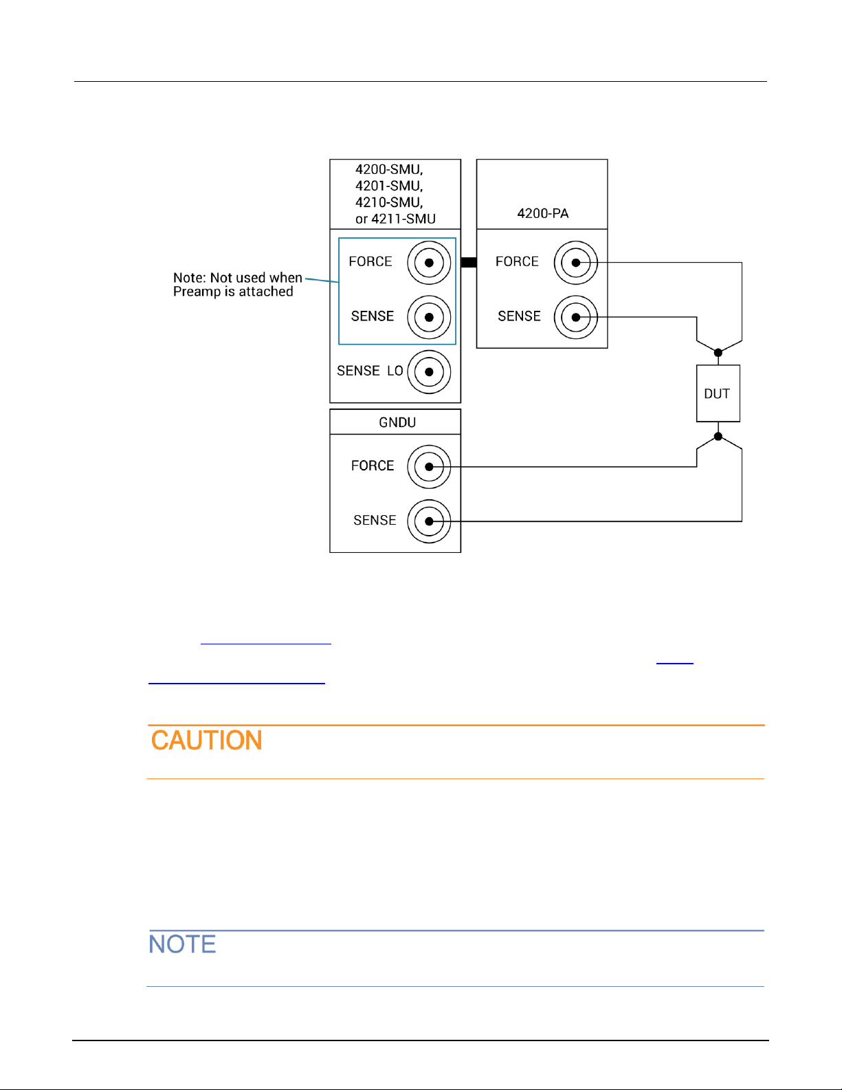
Model 4200A-SCS Source-Measure Unit (SMU) User's Manual Section 4: Source-measure hardware
4200A-SMU-900-01 Rev. A December 2020 4-15
Figure 66: Full-Kelvin preamplifier to ground unit connections
Ground unit terminals and connectors
Refer to Using the ground unit (on page 2-12) for the locations and configuration of the GNDU
terminals. Basic information about these connectors is summarized below. Refer to Basic
source-measure connections (on page 2-1) for additional information about signal connections for
ground units.
The maximum allowed voltage between circuit COMMON and chassis ground is ±32 V dc.
FORCE terminal
The FORCE terminal is a standard triaxial connector used as a return path for the SMU or
preamplifier FORCE current. The center pin is FORCE, the inner shield is GUARD, and the outer
shield is circuit COMMON.
The ground unit FORCE and GUARD signal terminals are connected to circuit COMMON.

Section 4: Source-measure hardware Model 4200A-SCS Source-Measure Unit (SMU) User's Manual
4-16 4200A-SMU-900-01 Rev. A December 2020
SENSE terminal
The SENSE terminal is a standard triaxial connector used to apply the ground unit SENSE signal to
the DUT in a remote sense application. The center pin is SENSE, the inner shield is GUARD, and the
outer shield is circuit COMMON. When the ground unit SENSE signal is connected to a DUT, all
SMU/preamplifier measurements are made relative to this DUT connection.
COMMON terminal
The COMMON terminal is a binding post that provides access to circuit COMMON.
Normally, a link is connected between ground unit COMMON and chassis ground, but it may be
necessary to remove the link to avoid measurement problems caused by ground loops or electrical
interference. Refer to Interference (on page 6-11) for details.

In this section:
Source-measure concepts ....................................................... 5-1
Guarding .................................................................................. 5-1
Local and remote sensing ................................ ........................ 5-5
Source or sink .......................................................................... 5-8
Source-measure considerations ............................................. 5-12
Sweep concepts ..................................................................... 5-19
Operation mode timing ........................................................... 5-22
Source-measure concepts
• Guarding (on page 5-1): An overview of guarding, guarding concepts, guard connections, and
test fixture guarding.
• Local and remote sensing (on page 5-5): Describes sensing, sensing concepts, and sense
selection.
• Source or sink (on page 5-8): Describes source and sink operations and summarizes the
operating boundaries.
• Source-measure considerations (on page 5-12): Details various source-measure circuit
configurations, including Source V, Measure V, and measure-only.
• Sweep concepts (on page 5-19): Covers the source-delay-measure cycle and provides an
overview of sweep waveforms.
Guarding
The purpose of guarding is to eliminate the effects of leakage current (and capacitance) that can exist
between FORCE and COMMON, or between SENSE and COMMON. The driven GUARD is always
enabled and provides a buffered voltage that is at the same level as the FORCE or SENSE HI
voltage (GUARD for both SOURCE and SENSE are the same signal that is referenced in FORCE). In
the absence of a driven guard, leakage in the external test circuit could be high enough to adversely
affect the performance of the SMU or preamplifier.
Leakage current can occur through parasitic or nonparasitic leakage paths. An example of parasitic
resistance is the leakage path across the insulation in a triaxial cable. An example of nonparasitic
resistance is the leakage path through a resistor that is connected in parallel to the device-under-test
(DUT).
Section 5
Source-measure concepts

Section 5: Source-measure concepts Model 4200A-SCS Source-Measure Unit (SMU) User's Manual
5-2 4200A-SMU-900-01 Rev. A December 2020
To avoid high voltage exposure that could result in personal injury or death, whenever the
interlock of the 4200A-SCS is asserted, the FORCE and GUARD terminals of the SMUs and
preamplifier should be considered to be at high voltage, even if they are programmed to a
nonhazardous voltage current.
Guard connections
GUARD is available at the inner shield of the FORCE and SENSE triaxial connectors for both the
SMU and the preamplifier, as shown in the following figure.
Figure 67: SMU and preamplifier triaxial connectors
The following figure shows the triaxial cable connections to the device under test (DUT). GUARD is
not connected in this example, but it can be routed internally to a test fixture, as described in Test
fixture guarding (on page 5-4).
Figure 68: GUARD connections

Model 4200A-SCS Source-Measure Unit (SMU) User's Manual Section 5: Source-measure concepts
4200A-SMU-900-01 Rev. A December 2020 5-3
Guarding concepts
Guarding is especially important with high-impedance circuits. Consider the comparison of the
unguarded and guarded circuits shown in the following figures. In both cases, FORCE is connected to
DUT HI and COMMON is connected to DUT LO.
In the unguarded circuit in the following figure, the cable leakage resistance, RL, is effectively in
parallel with the DUT, creating an unwanted leakage current, IL. This leakage current may seriously
affect readings, particularly at low current levels.
Figure 69: Unguarded circuit
In the guarded circuit of the following figure, the cable shield is driven by a unity-gain, low-impedance
amplifier (GUARD). Since the voltage across RL is nearly 0 V, the leakage current is effectively
eliminated. Current through any leakage resistance (RG) between the shield and COMMON may be
considerable, but it is of little consequence because it is supplied by the unity-gain amplifier rather
than the FORCE terminal of the SMU or preamplifier.
Figure 70: Guarded circuit

Section 5: Source-measure concepts Model 4200A-SCS Source-Measure Unit (SMU) User's Manual
5-4 4200A-SMU-900-01 Rev. A December 2020
Test fixture guarding
GUARD used to drive the inner shields of triaxial connecting cables can be routed within test fixtures.
Inside the test fixture, a triaxial cable can be used to extend the guard near to the DUT, and the guard
can be connected to a guard plate or shield that surrounds the DUT. The center conductor of the
cable is used for FORCE or SENSE, the inner shield is used for GUARD, and the outer shield is
COMMON.
To provide protection from shock hazards, an enclosure should be provided that surrounds
all live parts.
Nonconductive enclosures must be constructed of materials that are suitably rated for
flammability and the voltage and temperature requirements of the test circuit. Connect the
enclosure of all metal test fixtures to protective earth (safety ground). See your specific test
fixture for information. Nonconductive test fixtures must be rated to double the maximum
capability of the test equipment in the system.
For metallic enclosures, the test fixture chassis must be properly connected to protective
earth (safety ground). A grounding wire (16 AWG or larger) must be attached securely to the
test fixture at a screw terminal designed for safety grounding. The other end of the ground
wire must be attached to a known protective earth (safety ground).
The following figures show how guard can eliminate leakage current through the insulators in a
test fixture.
In the following figure, leakage current (IL) flows through the insulators (RL1 and RL2) to COMMON,
adversely affecting the low-current (or high-resistance) measurement of the DUT.
Figure 71: Test fixture - unguarded

Model 4200A-SCS Source-Measure Unit (SMU) User's Manual Section 5: Source-measure concepts
4200A-SMU-900-01 Rev. A December 2020 5-5
In the following figure, the driven GUARD is connected to the metal guard plate for the insulators.
Since the voltage on either end of RL1 is the same (0 V drop), no current can flow through the leakage
resistance path. As a result, the SMU or preamplifier measures only the current through the DUT.
Figure 72: Test fixture - guarded
The guard signal has an output impedance of 100 kΩ, which is effective only when connected to
high-impedance loads.
Local and remote sensing
The type of sensing, local or remote, is automatically selected depending on the connections.
Local sensing is adequate for many test and measurement situations. However, you should use
remote sensing for maximum accuracy for the following source-measure conditions:
• Test circuit impedance <1 kΩ
• Maximum voltage source or voltage measurement accuracy are required
Specified accuracies for both source and measure are achieved using remote sensing.

Section 5: Source-measure concepts Model 4200A-SCS Source-Measure Unit (SMU) User's Manual
5-6 4200A-SMU-900-01 Rev. A December 2020
To use local sensing, connect only SMU FORCE and ground unit FORCE (COMMON) to the DUT, as
shown in the following figure.
Figure 73: Local sensing overview
To use remote sensing, connect both SENSE and both FORCE terminals to the DUT as shown in the
following figure.
Figure 74: Remote sensing overview
See Basic source-measure connections (on page 2-1) for detailed information on various connection
methods. To simplify the figures, Guard connections are not shown.
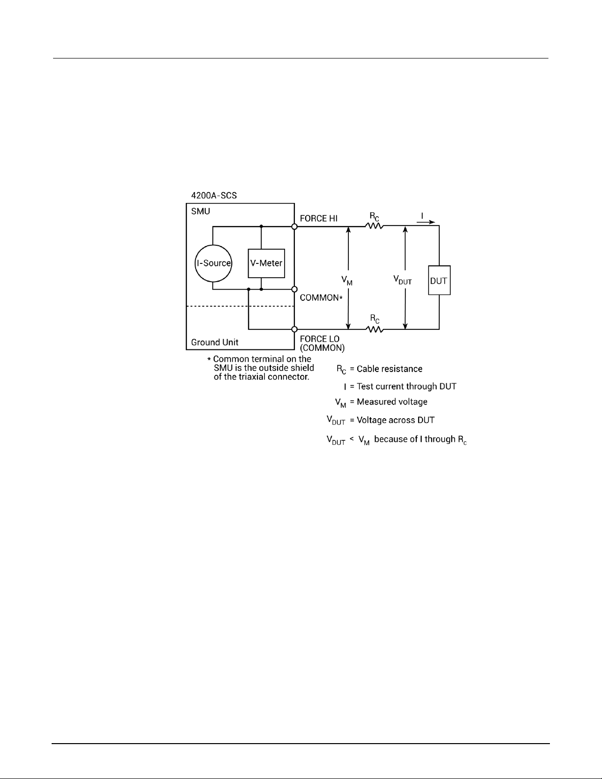
Model 4200A-SCS Source-Measure Unit (SMU) User's Manual Section 5: Source-measure concepts
4200A-SMU-900-01 Rev. A December 2020 5-7
Local sensing
Measurements made on devices with impedances above approximately 1 kΩ are generally made
using the local sensing method, as shown in the following figure. The SMU test current is forced
through the test leads and the DUT being measured, developing a voltage across the device (V
DUT
).
The SMU then measures the voltage across the DUT (VM) through the same set of test leads.
Figure 75: Local sensing
If you are measuring low-impedance DUTs, the local sensing method may give inaccurate results.
The cable resistance (RC) and the connection resistance (such as matrix crosspoint resistance or
prober-to-IC pad resistance) can be as high as 1 Ω. Since the test current (I) causes a small but
significant voltage drop across the cable resistance, the voltage measured by the SMU (VM) will not
be exactly the same as the voltage directly across the DUT (V
DUT
) and considerable error can result.
Typical cable resistances lie in the range of 1 mΩ to 100 mΩ, so it may be difficult to get accurate
local sensing measurements with DUT resistances below 100 Ω to 1 kΩ, depending on the
magnitudes of the cable resistance and contact resistance. In these cases, you may need to use
remote sensing.

Section 5: Source-measure concepts Model 4200A-SCS Source-Measure Unit (SMU) User's Manual
5-8 4200A-SMU-900-01 Rev. A December 2020
Remote sensing
The remote sensing method shown in the following figure is generally preferred for measurements on
low-impedance DUTs. With this configuration, the test current I is forced through the DUT through
one set of test cables, while the voltage across the DUT is measured through a second set of sense
cables. Although some small current (IS) may flow through these sense cables, it is usually negligible
(typically pA or less) and can generally be ignored. Since the voltage drop across the sense cables is
negligible, the voltage actually measured by the SMU (VM) is essentially the same as the voltage
across the DUT (V
DUT
).
Figure 76: Remote sensing
Source or sink
Depending on how they are programmed and what is connected to the output (load or source), the
SMUs can operate in any of the four quadrant of operation, as shown in the following figures. When
operating in the first (I) or third (III) quadrant, the SMUs are operating as a source (voltage and
current have the same polarity). As a source, the SMUs are delivering power to a load.
When operating in the second (II) or fourth (IV) quadrant, the SMUs are operating as a sink (voltage
and current have opposite polarity). As a sink, they dissipate power rather than sourcing it. An
external source (such as another SMU) or an energy storage device (such as a capacitor) can force
operation into the sink region.

Model 4200A-SCS Source-Measure Unit (SMU) User's Manual Section 5: Source-measure concepts
4200A-SMU-900-01 Rev. A December 2020 5-9
For example, if a second SMU that is sourcing +12 V is connected to the first SMU that is
programmed for +10 V, sink operation for the first SMU occurs in the second quadrant (source +V
and measure −I).
When using the current source as a sink, always set the voltage compliance to a level that is
higher than the external voltage level. Failure to do so could damage the SMU or preamplifier
due to excessive current that will flow into the unit.
4200-SMU and 4201-SMU source or sink
In the general operating boundaries in the following figure, the 100 mA, 20 V and 10 mA, 200 V
magnitudes are nominal values. The actual maximum output magnitudes of the 4200-SMU and
4201-SMU are 105 mA, 21 V and 10.5 mA, 210 V. Note that the boundaries are not drawn to scale.
Figure 77: 4200-SMU or 4201-SMU with a 4200-PA operating boundaries

Section 5: Source-measure concepts Model 4200A-SCS Source-Measure Unit (SMU) User's Manual
5-10 4200A-SMU-900-01 Rev. A December 2020
4210-SMU or 4211-SMU source or sink
In the following figure, the 1A, 20 V and 100 mA, 200 V magnitudes are nominal values. The actual
maximum output magnitudes of the 4210-SMU and 4211-SMU are 1.05 A, 21 V and 105 mA, 210 V.
The boundaries are not drawn to scale.
Figure 78: 4210-SMU or 4211-SMU with a 4200-PA operating boundaries

Model 4200A-SCS Source-Measure Unit (SMU) User's Manual Section 5: Source-measure concepts
4200A-SMU-900-01 Rev. A December 2020 5-11
4200-SMU and 4201-SMU sink boundaries
Nominal 4200-SMU and 4201-SMU boundaries are shown in the following figure. Note that actual
boundaries are 210 V at 10.5 mA or 21 V at 105 mA.
Figure 79: 4200-SMU or 4201-SMU with a 4200-PA operating boundaries

Section 5: Source-measure concepts Model 4200A-SCS Source-Measure Unit (SMU) User's Manual
5-12 4200A-SMU-900-01 Rev. A December 2020
4210-SMU and 4211-SMU sink boundaries
Nominal 4210-SMU and 4211-SMU sink boundaries are shown in the following figure. Actual
boundaries are 210 V at 105 mA or 21 V at 1.05 A.
Figure 80: 4210-SMU or 4211-SMU with a 4200-PA operating boundaries
Source-measure considerations
When configured to source current (I-Source), the SMU functions as a high-impedance current source
with voltage limit capability that can measure current (I-Meter) or voltage (V-Meter). The compliance
circuit limits the output voltage to the programmed value.
Source I, measure V or I
For voltage measurements, the SENSE selection (local or remote) determines where the
measurement is made. In local SENSE, voltage is measured at the FORCE and COMMON terminals.
In remote SENSE, voltage can be measured directly at the DUT using the SENSE and SENSE LO
terminals. This method eliminates any voltage drops that may be in the test cables or connections
between the SMU or preamplifier and the DUT.
The current source does not require or use the SENSE leads to enhance current source accuracy.

Model 4200A-SCS Source-Measure Unit (SMU) User's Manual Section 5: Source-measure concepts
4200A-SMU-900-01 Rev. A December 2020 5-13
Figure 81: Source I, measure V configuration
Source V, measure I or V
When configured to source voltage (V-Source) as shown in the following figure, the SMU functions as
a low-impedance voltage source with current limit capability and can measure current (I-Meter) or
voltage (V-Meter). The compliance circuit limits the current to the programmed value.
Sense circuitry is used to continuously monitor the output voltage and adjust the V-Source as needed.
The V-Meter senses the voltage at the FORCE and COMMON terminals (local SENSE) or at the DUT
(remote SENSE using the SENSE and SENSE LO terminals) and compares it to the programmed
voltage level. If the sensed level and the programmed value are not the same, the V-Source is
adjusted accordingly. Remote SENSE eliminates the effect of voltage drops in the test cables,
ensuring that the exact programmed voltage appears at the DUT.
Figure 82: Source V, measure I configuration

Section 5: Source-measure concepts Model 4200A-SCS Source-Measure Unit (SMU) User's Manual
5-14 4200A-SMU-900-01 Rev. A December 2020
Measure only (V or I)
The next figures show the configurations for using the SMU exclusively as a voltmeter or ammeter.
For both of these configurations, use local sensing.
For measure V, set the voltage compliance higher than the measured voltage. For measure I,
set the current compliance higher than the measured current.
In the following figure, the SMU is configured to measure voltage only by setting it to source 0 A and
measure voltage.
Figure 83: Measure voltage only
In the following figure, the SMU is configured to measure current only by setting it to source 0 V and
measure current. Note that to get positive (+) readings, conventional current must flow from FORCE
to COMMON.
Figure 84: Measure current only

Model 4200A-SCS Source-Measure Unit (SMU) User's Manual Section 5: Source-measure concepts
4200A-SMU-900-01 Rev. A December 2020 5-15
I-Source operating boundaries
Limit lines are boundaries that represent the operating limits of the SMU for a certain quadrant of
operation. The operating point can be anywhere inside (or on) these limit lines. The limit line
boundaries for the other quadrants are similar.
The following two figures show the operating boundaries for the I-Source. Only the first quadrant of
operation is covered; operation in the other three quadrants is similar.
As shown in the following figure, the 4200-SMU or 4201-SMU can output up to 105 mA at 21 V, or
10.5 mA at 210 V. The 4210-SMU or 4211-SMU can output up to 1.05 A at 21 V, or 105 mA at 210 V.
Figure 85: SMU current source output characteristics
The following figure shows the limit lines for the I-source. The current source limit line represents the
maximum source value possible for the selected current source range. For example, the current
source limit line is at 105 mA on the 100 mA current source range. The voltage compliance limit line
represents the actual compliance that is in effect.
Figure 86: SMU current source limit lines

Section 5: Source-measure concepts Model 4200A-SCS Source-Measure Unit (SMU) User's Manual
5-16 4200A-SMU-900-01 Rev. A December 2020
I-Source operation examples
The following figures show operation examples for resistive loads that are 2 kΩ and 8 kΩ, respectively.
For these examples, the SMU is programmed to source 10 mA and limit (compliance) 40 V. The SMU
is sourcing 10 mA to the 2 kΩ load, and subsequently measures 20 V. As shown, the load line for
2 kΩ intersects the 10 mA current source line at 20 V, which is below the programmed voltage limit.
Figure 87: Current source normal operation
The following figure shows what happens if the resistance of the load is increased to 8 kΩ. The DUT
load line for 8 kΩ intersects the 40 V voltage compliance limit line, placing the SMU in compliance. In
compliance, the SMU cannot source its programmed current (10 mA). For the 8 kΩ DUT, the SMU
only outputs 5 mA (at the 40 V limit).
Figure 88: Current source in compliance

Model 4200A-SCS Source-Measure Unit (SMU) User's Manual Section 5: Source-measure concepts
4200A-SMU-900-01 Rev. A December 2020 5-17
Notice that as resistance increases, the slope of the DUT load line increases. As resistance
approaches infinity (open output), the SMU sources virtually 0 mA at 40 V. However, as resistance
decreases, the slope of the DUT load line decreases. At zero resistance (shorted output), the SMU
sources 10 mA at virtually 0 V.
Regardless of the load, voltage will never exceed the programmed compliance of 40 V.
V-Source operating boundaries
The following figures show the operating boundaries for the voltage source. Only the first quadrant of
operation is covered; operation in the other three quadrants is similar.
As shown in the following figure, the 4200-SMU or 4201-SMU can output up to 21 V at 105 mA, or
210 V at 10.5 mA. The 4210-SMU or 4211-SMU can output up to 21 V at 1.05 mA, or 210 V at
1.5 mA.
Figure 89: V-Source operating boundaries
The following figure shows the limit lines for the voltage source. The voltage source limit line
represents the maximum source value possible for the selected voltage source range. For example,
the voltage source limit line is at 21 V for the 20 V source range. The current compliance limit line
represents the actual compliance in effect. These limit lines are boundaries that represent the
operating limits of the SMU for this quadrant of operation. The operating point can be anywhere
inside (or on) these limit lines. The limit line boundaries for the other quadrants are similar.
 Loading...