

Page 1

Model 4200A-SCS
Capacitance-Voltage Unit (CVU)
User's Manual
tek.com/keithley
4200A-CVU-900-01 Rev. B
March 2023
*P4200A-CVU-900-01B*
4200A-CVU-900-01B
Page 2

Capacitance-Volt age Unit (CVU)
Model 4200A-SCS
User's Manual
Page 3

© 2023, Keithley Instruments
Cleveland, Ohio, U.S.A.
All rights reserved.
Any unauthorized reproduction, photocopy, or use of the information herein, in whole or in part,
without the prior written approval of Keithley Instruments is strictly prohibited.
All Keithley Instruments product names are trademarks or registered trademarks of Keithley
Instruments, LLC. Other brand names are trademarks or registered trademarks of their
respective holders.
Actuate
®
Copyright © 1993-2003 Actuate Corporation.
All Rights Reserved.
Microsoft, Visual C++, Excel, and Windows are either registered trademarks or trademarks of
Microsoft Corporation in the United States and/or other countries.
Document number: 4200A-CVU-900-01 Rev. B March 2023
Page 4

Safety precaut ions
The following safety precautio ns should be observed before using this product and any associated ins t rum enta tion. Although
some instruments and accessories would normally be used with nonhazardous voltages, there are situations where hazardous
conditions may be present.
This product is intended for use by personnel who recognize shock hazards and are familiar with the safety precautions required
to avoid possible injury. Read and follow all installation, operation, and maintenance information carefully before using the
product. Refer to the user documentation for complete product specifications.
If the product is used in a manner not specified, the protection provided by the product warranty may be impaired.
The types of product users are:
Responsible body is the individual or group responsible for the use and maintenance of equipment, for ensuring that the
equipment is operated within its specifications and operating limits, and for ensuring that operators are adequately trained.
Operators use the product for its intended function. They must be trained in electrical safety procedures and proper use of the
instrument. They must be protected from electric shock and contact with hazardous live circuits.
Maintenance personnel perform routine procedures on the product to keep it operating properly, for example, setting the line
voltage or replacing consumable materials. Maintenance procedures are described in the user documentation. The procedures
explicitly state if the operator may perform them. Otherwise, they should be performed only by service personnel.
Service personnel are trained to work on live circuits, perform safe installations, and repair products. Only properly trained
service personnel may perform installation and service procedures.
Keithley products are designed for use with electrical signals that are measurement, control, and data I/O connections, with low
transient overvoltages, and must not be directly connected to mains voltage or to voltage sources with high transient
overvoltages. Measurement Category II (as referenced in IEC 60664) connections require protection for high transient
overvoltages often associate d with local AC mains connections. Certain Keithley measuring instruments may be connected to
mains. These instruments will be marked as category II or higher.
Unless explicitly allowed in the specif icat ion s, opera ting manual, and instrument labels, do not connect any instru ment to mains.
Exercise extreme caution when a shock hazard is present. Lethal voltage may be present on cable connector jacks or test
fixtures. The American National Standards Institute (ANSI) states that a shock hazard exists when voltage levels greater than
30 V RMS, 42.4 V peak, or 60 VDC are present. A good safety practice is to expect that hazardous voltage is present in any
unknown circuit before measuring.
Operators of this product must be protected from electric shock at all times. The responsible body must ensure that operators
are prevented access and/or insulated from every connection point. In some cases, connections must be exposed to potential
human contact. Product operators in these circumstances must be trained to protect themselves from the risk of electric shock. If
the circuit is capable of operating at or above 1000 V, no conductive part of the circuit may be exposed.
Do not connect switching cards directly to unlimited power circuits. They are intended to be used with impedance-limited
sources. NEVER connect switching cards directly to AC mains. When connecting sources to switching cards, install protective
devices to limit fault current and voltage to the card.
Before operating an instrument, ensure that the line cord is connected to a properly-grounded power receptacle. Inspect the
connecting cables, test leads, and jumpers for possible wear, cracks, or breaks before each use.
When installing equipment where access to the main power cord is restricted, such as rack mounting, a separate main input
power disconnect device must be provided in close proximity to the equipment and within easy reach of the operator.
For maximum safety, do not touch the product, test cables, or any other instruments while power is applied to the circuit under
test. ALWAYS remove power from the entire test system and discharge any capacitors before connecting or disconnecting
cables or jumpers, installing or removing switching cards, or making internal changes, such as installing or removing jumpers.
Do not touch any object that could provide a current path to the common side of the circuit under test or power line (earth)
ground. Always make measurements with dry hands while standing on a dry, insulated surface capable of withstanding the
voltage being measured.
Page 5
For safety, instruments and accessories must be used in accordance with the operating instructions. If the instruments or
accessories are used in a manner not specified in the operating instructions, the protection provided by the equipment ma y be
impaired.
Do not exceed the maximum signal levels of the instruments and accessories. Maximum signal levels are defined in the
specifications and operating information and shown on the instrument panels, test fixture panels, and switching cards.
When fuses are used in a product, replace with the same type and rating for continued protection against fire hazard.
Chassis connections must only be used as shield connections for measuring circuits, NOT as protective earth (safety ground)
connections.
If you are using a test fixture, keep the lid closed while power is applied to the device under test. Safe operation requires the use
of a lid interlock.
If a
The
screw is present, connect it to protective earth (safety ground) using the wire recommended in the user documentatio n.
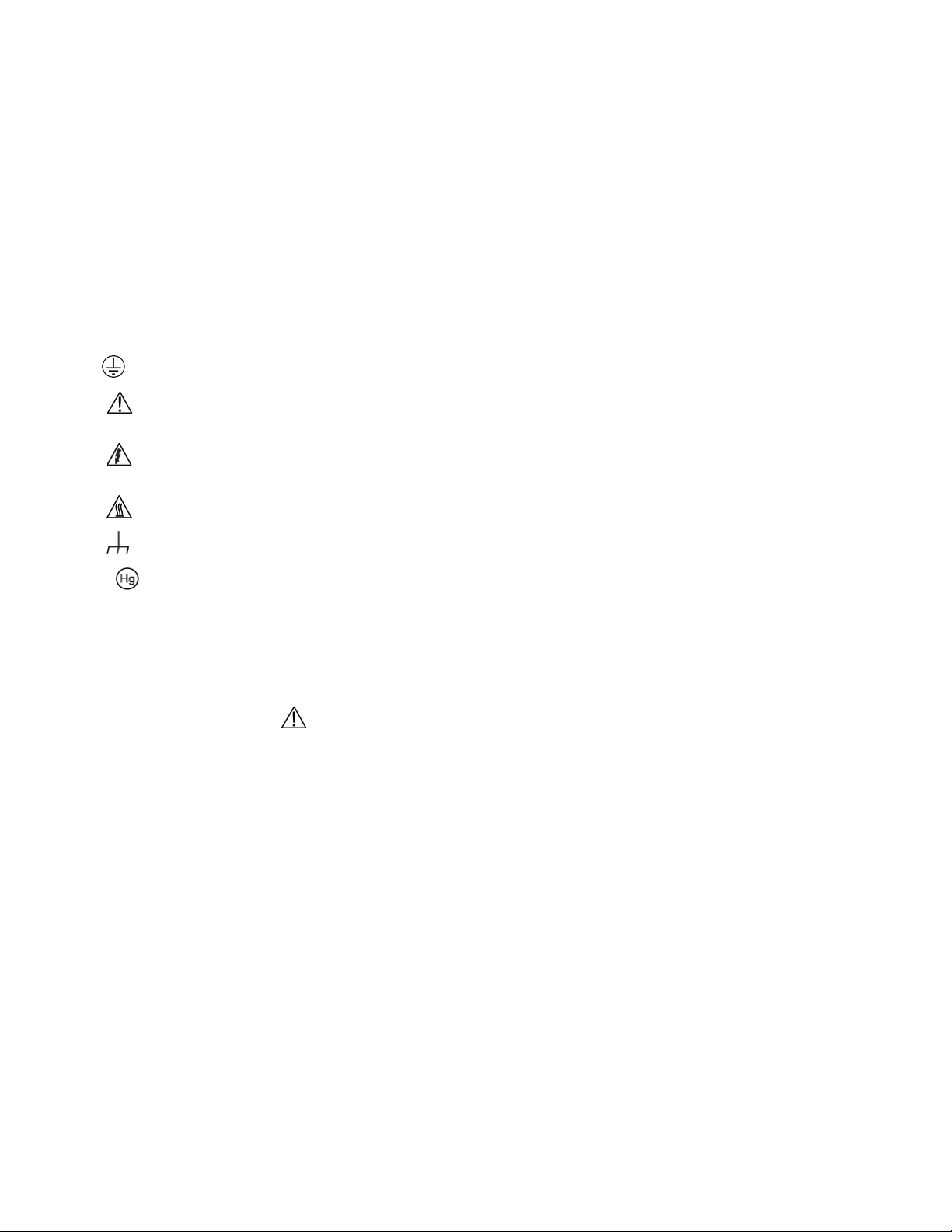
symbol on an instrument means caution, risk of hazard. The user must refer to the operating instructions located in the
user documentation in all cases where the symbol is mark ed on the instr u ment .
The
symbol on an instrument means warning, risk of electric shock. Use standard safety precautions to avoid personal
contact with these voltages.
The symbol on an instrument shows that the surface may be hot. Avoid personal contact to prevent burns.
The
If this
symbol indi cates a connection terminal to the equipment frame.
symbol is on a product, it indicates that mercury is present in the display lamp. Please note that the lamp must be
properly disposed of according to federal, state, and local laws.
The WARNING heading in the user documentation explains hazards that might result in personal injury or death. Always read
the associated information very carefully before performing the indicated procedure.
The CAUTION heading in the user documentation explains h azard s that coul d dama ge the instrument. Such damage may
invalidate the warranty.
The CAUTION heading with the
symbol in the user documentation explains hazards that could result in moderate or minor
injury or damage the instrument. Always read the as soc iate d infor mation very carefully before performing the indicated
procedure. Damage to the instrument may invalidate the warranty.
Instrumentation and accessories shall not be connected to humans.
Before performing any maintenance, disconnect the line cord and all test cables.
To maintain protection from electric shock and fire, replacement components in mains circuits — including the power
transformer, test leads, and input jacks — must be purchased from Keithley. Standard fuses with applicable national safety
approvals may be used if the rating and type are the same. The detachable mains power cord provided with the instrument may
only be replaced with a similarly rated power cord. Other components that are not safety-related may be purcha sed fr om ot her
suppliers as long as they are equivalent to the original component (note that selected parts should be purchased only through
Keithley to maintain accuracy and functionality of the product). If you are unsure about the applicability of a replacement
component, call a Keithley office for information.
Unless otherwise noted in product-specific literature, Keithley instruments are designed to operate indoors only, in the following
environment: Altitude at or below 2,000 m (6,562 ft); temperature 0 °C to 50 °C (32 °F to 122 °F); and pollution degree 1 or 2.
To clean an instrument, use a cloth dampened with deionized water or mild, water-based cleaner. Clean the exterior of the
instrument only. Do not apply cleaner directly to the instrument or allow liquids to enter or spill on the instrument. Products that
consist of a circuit board with no case or chassis (e.g., a data acquisition board for installation into a computer) should never
require cleaning if handled according to instructions. If the board becomes contaminated and operation is affected, the board
should be returned to the factory for proper cleaning/servicing.
Safety precaution revision as of June 2018.
Page 6

Table of contents
Introduction .............................................................................................................. 1-1
Introduction .......................................................................................................................... 1-1
Capacitance-Voltage Unit (CVU) ......................................................................................... 1-1
Test signal ............................................................................................................................ 1-2
Connections ............................................................................................................. 2-1
CVU connections ................................................................................................................. 2-1
Connection notes ...................................................................................................................... 2-1
Prober accessories for the CVU ................................................................................................ 2-2
Typical CVU test connections to a DUT .................................................................................... 2-3
Simplified model of a DUT......................................................................................................... 2-4
Typical test connections to a probe card ................................................................................... 2-5
Typical CVU matrix card connections ....................................................................................... 2-5
Connection compensation ................................................................................................... 2-8
Generate open connection compensat ion dat a ......................................................................... 2-8
Generate short connection compen sat ion data ....................................................................... 2-11
Generate load connection compensatio n dat a ........................................................................ 2-13
Compensation data ................................................................................................................. 2-15
Enable compensation .............................................................................................................. 2-15
ABB unbalance errors ............................................................................................................. 2-17
CVU Confidence Check ..................................................................................................... 2-17
Run an open check and short check ....................................................................................... 2-18
CVU Real-Time Measurement ........................................................................................... 2-19
Setting up CVUs in Clarius ...................................................................................... 3-1
CVU project example ........................................................................................................... 3-1
Select a project ......................................................................................................................... 3-1
Configure the test ...................................................................................................................... 3-3
Run the test and review results ................................................................................................. 3-3
Selecting the DC Operation Mode ....................................................................................... 3-5
Voltage Bias .............................................................................................................................. 3-5
Voltage Linear Sweep ............................................................................................................... 3-5
Voltage List Sweep ................................................................................................................... 3-5
Voltage Step.............................................................................................................................. 3-6
DC Gnd operation mode - CVU ................................................................................................. 3-6
Selecting the Freq Operation Mode ..................................................................................... 3-6
Frequency Single Freq .............................................................................................................. 3-6
Frequency Linear Sweep .......................................................................................................... 3-6
Freq Log Sweep ........................................................................................................................ 3-7
Freq List Sweep ........................................................................................................................ 3-7
Freq Step .................................................................................................................................. 3-7
Making additional test settings ............................................................................................. 3-8
Typical test setups with timing diagrams ............................................................................. 3-9
DC bias function and sweep characteristics .............................................................................. 3-9
CVU using voltage bias ........................................................................................................... 3-11
CVU using voltage sweep ....................................................................................................... 3-12
CVU using voltage li st sweep .................................................................................................. 3-13
Page 7

Table of contents
User's Manual
Model 4200A-SCS Capacitance-Voltage Unit (CVU)
CVU using a dc voltage bias and a frequency sweep ............................................................. 3-15
CVU frequency sweep - DC step ............................................................................................ 3-17
CVU voltage linear sweep - f requency step ............................................................................ 3-19
Force-measure timing ........................................................................................................ 3-22
Bias function timing ................................................................................................................. 3-22
Sweep function timing ............................................................................................................. 3-23
CVU - all terminal parameters ............................................................................................ 3-23
Presoak ................................................................................................................................... 3-23
Start ........................................................................................................................................ 3-23
Stop ......................................................................................................................................... 3-23
Step (voltage sweep) .............................................................................................................. 3-23
List Values............................................................................................................................... 3-24
Freq Operation Mode .............................................................................................................. 3-24
Start (Freq Operation Mode) ................................................................................................... 3-24
Stop (Freq Operation Mode) ................................................................................................... 3-24
Step (Freq Operation Mode) ................................................................................................... 3-24
Frequency Points (Freq Operation Mod e) ............................................................................... 3-25
AC Drive Signal ....................................................................................................................... 3-25
Points ...................................................................................................................................... 3-25
Points (list or segment sweep) ................................................................................................ 3-25
Dual Sweep ............................................................................................................................. 3-25
DC Bias ................................................................................................................................... 3-26
Frequency ............................................................................................................................... 3-26
Parameters.............................................................................................................................. 3-26
Param1 Column Name ............................................................................................................ 3-27
Param2 Column Name ............................................................................................................ 3-28
Report Test Conditions ........................................................................................................... 3-28
DCV Column Name ................................................................................................................. 3-28
Freq Column Name ................................................................................................................. 3-28
Report Status (CVU) ............................................................................................................... 3-29
Open ....................................................................................................................................... 3-29
Short ....................................................................................................................................... 3-29
Load ........................................................................................................................................ 3-29
Cable Length ........................................................................................................................... 3-29
CVU Terminal Settings Advanced settings and circuits ..................................................... 3-30
AC Source V ........................................................................................................................... 3-31
AC Measure I Range ............................................................................................................... 3-31
DC Source V ........................................................................................................................... 3-32
DC Offset ................................................................................................................................ 3-32
Capacitance Range Estimator ................................................................................................. 3-32
CVU test settings ............................................................................................................... 3-32
CVU speed settings ................................................................................................................ 3-33
Report Timestamps ................................................................................................................. 3-37
Test Mode ............................................................................................................................... 3-38
Sweep Delay ........................................................................................................................... 3-39
Interval .................................................................................................................................... 3-39
Number of Samples ................................................................................................................ 3-39
Hold Time ................................................................................................................................ 3-39
Disable outputs at completion - CVU ...................................................................................... 3-40
Output Values ......................................................................................................................... 3-40
C-V projects .............................................................................................................. 4-1
C-V projects ......................................................................................................................... 4-1
BJT Capacitance Tests (cvu-bjt) .......................................................................................... 4-3
cvu-bjt connections ................................................................................................................... 4-3
Formulas and constants ............................................................................................................ 4-5
Page 8

Model 4200A
contents
-SCS Capacitance-Voltage Unit (CVU) User's Manual Table of
c-cb0 test................................................................................................................................... 4-5
c-ce0 test................................................................................................................................... 4-5
c-be0 test .................................................................................................................................. 4-6
BJT I-V and C-V Tests Using 4200A-CVIV Multi-Switch Project (cvu-bjt-cviv) ................... 4-7
Capacitor I-V and C-V Measurements with Series 700 Project (cap-iv-cv-matrix) .............. 4-8
cap-iv-cv-matrix project summary ............................................................................................. 4-9
cap-iv-cv-matrix connections ................................................................................................... 4-10
Formulas and constants .......................................................................................................... 4-11
connect test ............................................................................................................................. 4-11
iv-cap test ................................................................................................................................ 4-11
connect-cv test ........................................................................................................................ 4-12
cv-capacitor test ...................................................................................................................... 4-12
Capacitor Measurements (cap-measurements) ................................................................ 4-13
cvu-capacitor connection s ....................................................................................................... 4-13
Formulas and constants .......................................................................................................... 4-13
cv-10 pF test ........................................................................................................................... 4-13
cf-10 pF test ............................................................................................................................ 4-14
Carbon Nanotube Transistor Characterization Project (cntfet -characterization) ............... 4-14
Demo project (default) ........................................................................................................ 4-15
cv-nmosfet test ........................................................................................................................ 4-15
cv-diode test ............................................................................................................................ 4-15
cv-cap test ............................................................................................................................... 4-15
Diode Project (diode) ......................................................................................................... 4-16
diode connections ................................................................................................................... 4-17
diode project formulas and constants ...................................................................................... 4-18
diode-cvsweep test ................................................................................................................. 4-19
diode-c-2vsv test ..................................................................................................................... 4-20
diode-dopingprofile test ........................................................................................................... 4-21
High-Voltage C-V Tests Project (cvu-highv) ...................................................................... 4-21
High Voltage C-V Tests Using 4200A-CVIV Bias Tee Project (cviv-bias-highv) ............... 4-22
MOS Capacitor C-V Project (cvu-moscap) ........................................................................ 4-23
MOS capacitor C-V curves ...................................................................................................... 4-24
Accumulation region ................................................................................................................ 4-24
Depletion region ...................................................................................................................... 4-25
Inversion region ....................................................................................................................... 4-25
cvu-moscap connections ......................................................................................................... 4-26
cvu-moscap project formulas .................................................................................................. 4-27
cvu-moscap project constants ................................................................................................. 4-34
moscap-cvsweep test .............................................................................................................. 4-35
moscap-c-2vsv test ................................................................................................................. 4-35
moscap-dopingprofile test ....................................................................................................... 4-37
Compensating for series resistance ........................................................................................ 4-38
Extracting MOS device parameters from C-V measurements ................................................. 4-40
MOS Capacitor Lifetime Test Project (moscap-lifetime) .................................................... 4-46
moscap-lifetime connections ................................................................................................... 4-46
moscap-lifetime formulas and constants ................................................................................. 4-47
c-v test .................................................................................................................................... 4-50
c-t test ..................................................................................................................................... 4-51
gni-w-wf test ............................................................................................................................ 4-51
MOS Capacitor Mobile Ion Project (moscap-mobile-ion) ................................................... 4-54
moscap-mobile-ion connections .............................................................................................. 4-57
Formulas and constants .......................................................................................................... 4-57
Run the project ........................................................................................................................ 4-58
cv-vfb1 test .............................................................................................................................. 4-58
Page 9

Table of contents
User's Manual
Model 4200A-SCS Capacitance-Voltage Unit (CVU)
bias-pos test ............................................................................................................................ 4-59
hotchuck action ....................................................................................................................... 4-60
cv-vfb2 test .............................................................................................................................. 4-60
bias-neg test ............................................................................................................................ 4-60
hotchuck action ....................................................................................................................... 4-61
cv-vfb3 test .............................................................................................................................. 4-61
MOSFET 3-Terminal C-V Tests Using the 4200A-CVIV Bias Tees (mosfet-cviv-cv-bias-tees and
mosfet-cviv-cv-bias-tees-400V) ......................................................................................... 4-62
MOSFET I-V and C-V Tests Using 4200A-C VIV Multi-Switch Project (mosfet-cviv)......... 4-62
MOSFET Project (mosfet) .................................................................................................. 4-63
mosfet connections ................................................................................................................. 4-64
mosfet formulas and constants ............................................................................................... 4-65
g-to-sdb and mosfet-dopingprofile Analyze sheet ................................................................... 4-70
Solar Cell Project (solarcell) ............................................................................................... 4-70
solarcell connections ............................................................................................................... 4-71
solarcell formulas and constants ............................................................................................. 4-72
fwd-ivsweep test ...................................................................................................................... 4-76
rev-ivsweep test ...................................................................................................................... 4-76
solarcell-cvsweep test ............................................................................................................. 4-77
solarcell-c-2vsv test ................................................................................................................. 4-77
cfsweep test ............................................................................................................................ 4-78
Interconnect Capacitance C-V Sweep test (cv-sweep) ..................................................... 4-79
cv-sweep connections ............................................................................................................. 4-79
Formulas and constants .......................................................................................................... 4-79
Analyze sheet .......................................................................................................................... 4-80
Nanowire tests ................................................................................................................... 4-80
cvu-nanowire connection s ....................................................................................................... 4-80
Formulas and constants .......................................................................................................... 4-81
cv-gd and cv-sd tests .............................................................................................................. 4-82
Make C-V measurements on a MOSCAP ................................................................ 5-1
Introduction .......................................................................................................................... 5-1
Equipment required .............................................................................................................. 5-1
Device connections .............................................................................................................. 5-2
Connect the 4200A-SCS to the DUT ......................................................................................... 5-2
Set up the measurements in Clarius .................................................................................... 5-4
Search for and select a project .................................................................................................. 5-4
Configure the test ...................................................................................................................... 5-5
Perform offset compensation .................................................................................................... 5-8
Run the test ............................................................................................................................. 5-11
View and analyze the test results ............................................................................................ 5-11
Page 10

Test signal ................................................................................ 1-2
In this section:
Introduction .............................................................................. 1-1
Capacitance-Voltage Unit (CVU) .............................................. 1-1
Introduction
This document provides information about the 4210-CVU and 4215-CVU capacitance-v olta ge unit s,
including:
• Connections (on page 2-1): Basic information on connecting CVUs to DUTs, making test
equipment connections, making control and data connections, and configuring the system
in KCon.
Section 1
Introduction
• Setting up CVUs in Clarius (on page 3-1): Provides a brief example of setting up CVUs in Clarius
and descriptions of the terminal and test settings.
• C-V projects (on page 4-1): Provides descriptions of the C-V projects in Clarius.
• Make C-V measurements on a MOSCAP (on page 5-1): Presents a step-by-step
application example.
Capacitance-Vo l tage Unit (CVU)
The 4210-CVU and 4215-CVU Multi-Frequency Capacitance-Voltage Units are impedance
measurement modules that can be installed in the 4200A-SCS.
Capacitance-voltage (C-V) measurements are often used to characterize the gate oxide thickness,
oxide defect density, and doping profile of MOSFETs. In these measurements, as the gate voltage
varies, the capacitance of the gate to the drain and source changes. Capacitance measurements are
typically made using an ac technique. The CVUs measure ac impedance by applying a dc bias
voltage and sourcing an ac voltage across the device under test (DUT) and then measuring the
resultant ac current and phase angle.
The 4210-CVU operates from 1 kHz to 10 MHz. The ac test signal (10 mV
dc voltage biased from −30 V to +30 V.
to 100 mV
RMS
) can be
RMS
The 4215-CVU operates from 1 kHz to 10 MHz at 1 kHz resolution. The ac test signal (10 mV to
1 V
) can be dc voltage biased from −30 V to +30 V.
RMS
Page 11

Section
User's Manual
1: Introduction Model 4200A-SCS Capacitance-Voltage Unit (CVU)
Test signal
The test signal can be set for the following frequencies.
For the 4210-CVU:
• 1 kHz to 10 kHz in 1 kHz increments
• 10 kHz to 100 kHz in 10 kHz increments
• 100 kHz to 1 MHz in 100 kHz increments
• 1 MHz to 10 MHz in 1 MHz increments
The ac signal output level can be set from 10 mV
to 100 mV
RMS
impedance is 100 Ω (typical). The ac voltage measure range is 100 mV
RMS
(1 mV
RMS
resolution). The output
RMS
.
The ranges available to measure current are 1 μA, 30 μA, or 1 mA. With autorange selected, range
selection is done automatically.
For the 4215-CVU:
• 1 kHz to 10 MHz in 1 kHz increments
The ac signal output level can be set from 10 mV
RMS
to 1 V
impedance is 100 Ω (typical). The ac voltage measure range is 1 mV
The ranges available to measure current are 1 μA, 30 μA, or 1 mA. With autorange selected, range
selection is done automatically.
RMS
(1 mV
resolution). The output
RMS
.
RMS
1-2 4200A-CVU-900-01 Rev. B March 2023
Page 12

CVU Real-Time Measurement ............................................... 2-19
In this section:
CVU connections ..................................................................... 2-1
Connection compensation ........................................................ 2-8
CVU Confidence Check ......................................................... 2-17
CVU connections
The CVU is shipped with four red 1.5 m SMA cables (plug-to-plug, 100 Ω). These characterized
cables must be used for connection to the CVU to achieve optimum performance.
Section 2
Connections
If you have the 4200-CVU-PROBER-KIT, you also have four red 3 m SMA cables
(plug-to-plug, 100 Ω).
If you have the 4225-RPM Remote Amplifier/Switch Module (available as an accessory for the
4225-PMU UltraFast Pulse Measure Unit), you can use the RPM for switching between SMUs, CVUs,
and PMUs. For switching connection information, refer to “Use the RPM to switch the SMU, CVU, and
PMU” in Model 4200A-SCS Pulse Card (PGU and PMU) User’s Manual (4200A-PMU-900-01).
Connection notes
• Use only the supplied red SMA cables for connections to the 4210-CVU or 4215-CVU.
• Do not use a mix of cable lengths on different CVU terminals.
• Use the supplied torque wrench to tighten SMA cable connectors to 8 in. lb.
• In Clarius, the cable length setting of a test must match the length of the SMA cables used for
your setup.
• If you need to run connection compensation, do it after setting up connections or after making
changes to existing connections, but before running any tests. See the Connection compensation
(on page 2-8) topic.
• When making connections from the CVU to the device under test (DUT), make sure the shields of
the SMA cables are connected as close as possible to the DUT.
• Use coaxial cables to extend SMA shielding to the DUT, then connect them.
Page 13
Section
User's Manual
Keithley part number or
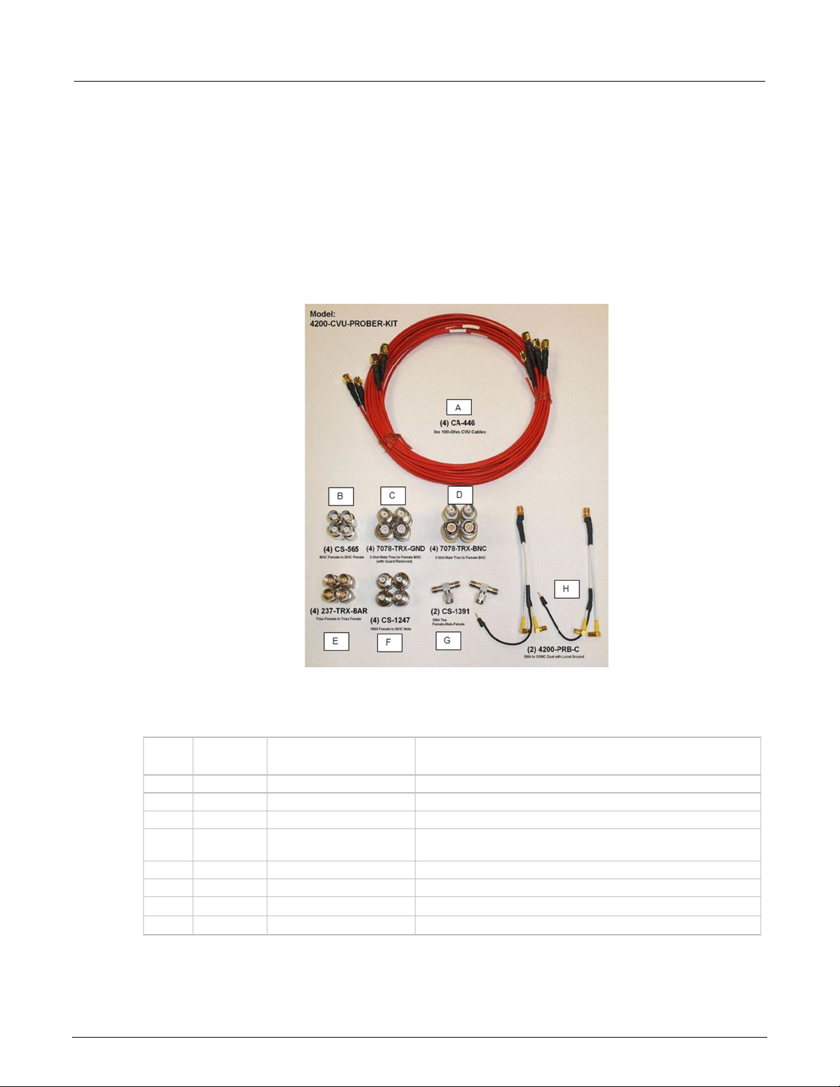
A 4 CA-446
Red SMA cables, male to male, 100 Ω, 3 m
B 4 CS-565
BNC female to BNC female adapter
C 4 7078-TRX-GND
Triaxial male to BNC female adapter (with guard remov ed)
D 4 7078-TRX-BNC
Triaxial male to BNC female adapter (with guard conne cted
to the inner shield of the adapter)
E 4 237-TRX-BAR
Triaxial female to triaxial female adapter
F 4 CS-1247
SMA female to BNC male adapter
G 2 CS-1391
SMA Tee adapter (female, male, female)
H 2 4200-PRB-C
SMA to SSMC dual (with local ground)
2: Connections Model 4200A-SCS Capacitance-Voltage Unit (CVU)
Prober accessories for the CVU
The Model 4200-CVU-PROBER-KIT is an accessory kit that provides connections to a wide variety of
prober and manipulator types. This kit contains a combination of triaxial and BNC adapters and
barrels that accommodate most prober connection requirements.
The following figure shows the accessories that are included in the kit.
Figure 1: Model 4200-CVU-PROBER-KIT
The following table lists the cables and adapters provided with the prober kit.
Supplied cables and adapters for the Model 4200-CVU-PROBER-KIT
Item Quantity
model number Description
When using the Model 4200-PRB-C cables (item H), be sure you jumper the shields together at the
probe tips. Each stackable black banana plug is connected to the outer shield of the cables.
2-2 4200A-CVU-900-01 Rev. B March 2023
Page 14
Mo
del 4200A-SCS Capacitance-Voltage Unit (CVU) User's Manual Section 2:
Connections
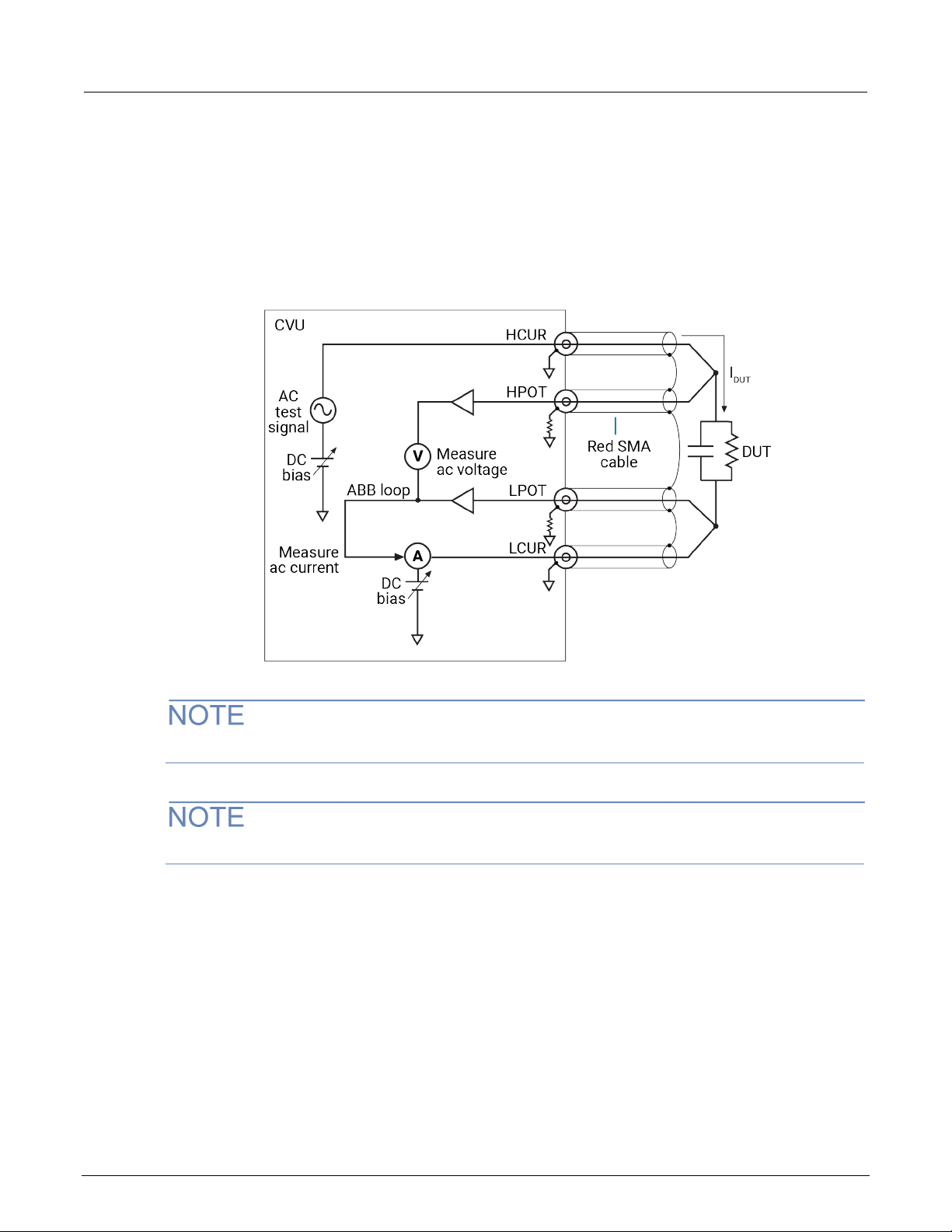
Typical CVU test connections to a DUT
The shields of the SMA cables must be connected together and extended as far as possible to the
device under test (DUT), as shown in the following figure.
Use the supplied torque wrench to tighten the SMA connections to 8 in. lb.
Figure 2: Measurement circuit (simplified)
You can swap the HCUR and HPOT and LCUR and LPOT terminal functionality in Clarius.
The shields of the red SMA cables must be connected together near the DUT.
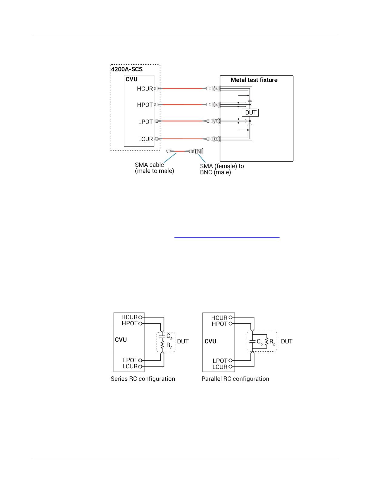
The following figure shows typical connections to a DUT installed in a test fixture that has BNC
bulkhead connectors. Use a conductive test fixture with the bulkhead connectors mounted directly to
the test fixture. Do not use insulators between the connectors and test fixture. The cables and
adapters shown are the ones supplied with the 4210-CVU or 4215-CVU.
4200A-CVU-900-01 Rev. B March 2023 2-3
Page 15
Section
User's Manual
2: Connections Model 4200A-SCS Capacitance-Voltage Unit (CVU)
Figure 3: Typical CVU connections to a DUT in a test fixture
Simplified model of a DUT
The CVU makes ac impedance measurements (Z
) of the device under test (DUT) by sourcing an
DUT
ac test voltage across the device and measuring the resulting ac current and ac voltage.
The ac current is measured as shown in Typical CVU test connections to a DUT (on page 2-3
).
The HCUR/HPOT and LCUR/LPOT terminal pairs are interchangeable. Each provides the full
capability of the other pair.
The simplified model of a DUT is a resistor and a capacitor. As shown in the following figure, the CVU
can measure the DUT as a series configuration of the resistor-capacitor (RC) or as a parallel
RC configuration.
Figure 4: Measure models (simplified)
2-4 4200A-CVU-900-01 Rev. B March 2023
Page 16
Model 4200A
Connections
-SCS Capacitance-Voltage Unit (CVU) User's Manual Section 2:
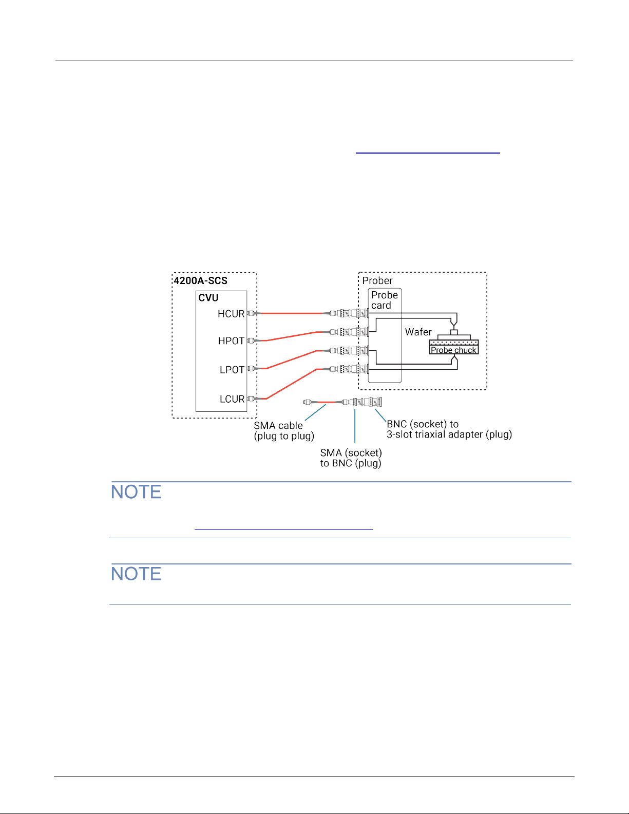
Typical test connections to a probe card
The 4200-CVU-PROBER-KIT includes 3 meter SMA cables and connection accessories to connect
the 4210-CVU or 4215-CVU to a probe card. Refer to Prober accessories for the CVU (on page 2-2
for a list of the supplied items.
The following figure shows typical test connections to a probe card. The connections use triaxial
socket connectors. The probe kit includes two types of BNC to triaxial adapters. The 7078-TRX-BNC
has the guard connected to the inner shield of the adapter. The 7078-TRX-GND has the guard
disconnected. In most applic ations , the 707 8-TRX-BNC is the preferred adapter.
Figure 5: Typical connections to a probe card
)
The shields of the SMA cables must be connected together and extended as far as possible to the
DUT, as shown in Typical CVU test connections to a DUT (on page 2-3
If the probe card uses BNC (socket) connectors, you do not need the BNC-to-triaxial adapters.
Typical CVU matrix card connections
In your project, you can automate the use of a CVU and other instrumentation using a switching
matrix and actions to control the switching. When the project is run, the switching matrix automatically
makes the required instrument connections for each test in the project.
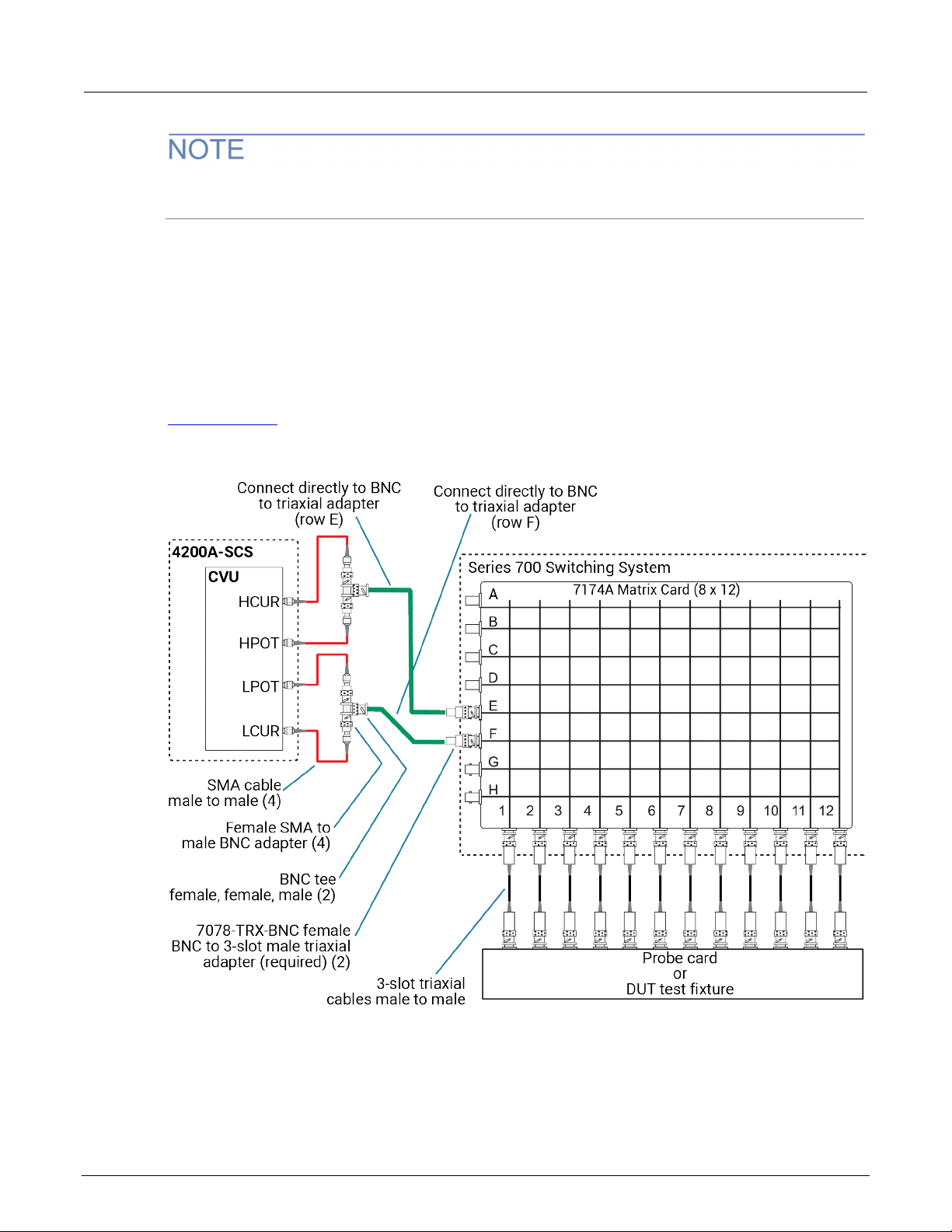
The next figures show typical connecti ons for a switch s y stem using a Series 700 Switch in g Syste m
with the 7174A Matrix Card installed.
).
4200A-CVU-900-01 Rev. B March 2023 2-5
Page 17
Section
User's Manual
2: Connections Model 4200A-SCS Capacitance-Voltage Unit (CVU)
You can also use the 7072 Matrix Card for C-V testing. If you are using the 7072, you must use rows
G and H and local (2-w ir e) s ens ing.
The SMA cables and adapters shown in the following figures are supplied with the CVU or the
4200-CVU-PROBER-KIT. The triaxial and BNC cables are not supplied. The prober kit includes two
types of BNC-to-triaxial adapters that connect directly to the rows of the matrix. The 7078-TRX-BNC
has the guard connected to the inner shield of the adapter. The 7078-TRX-GND has the guard
disconnected.
This figure shows connections for local (2-wire) sensing with the CVU connected to rows E and F of
the matrix. This is the connection scheme for the cap-iv-cv-matrix project. For details, see
cap-iv-cv-matrix (on page 4-8
).
Figure 6: Test connections for a switching matrix - local (2-wire) sensing
2-6 4200A-CVU-900-01 Rev. B March 2023
Page 18
Model 4200A
Connections
-SCS Capacitance-Voltage Unit (CVU) User's Manual Section 2:
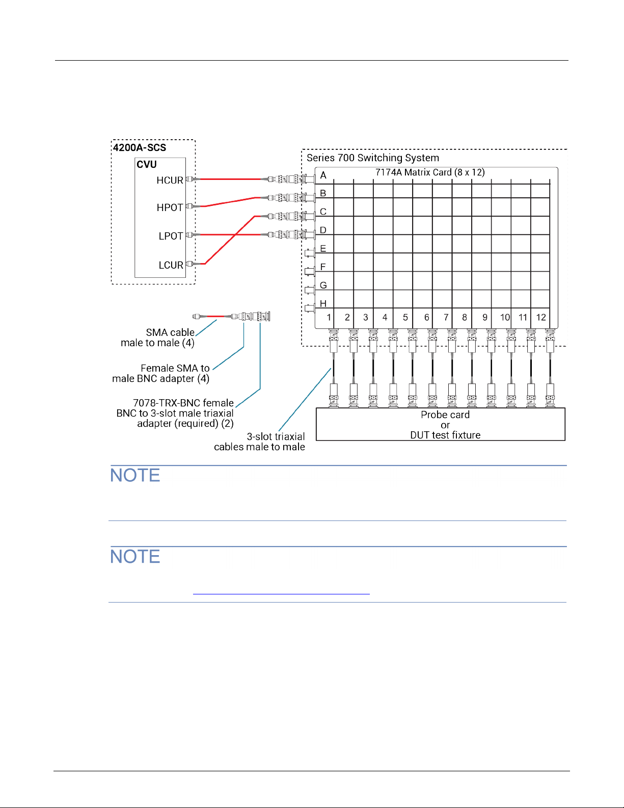
The following figure shows connections for remote (4-wire) sensing.
Figure 7: Test connections for a switching matrix - remote (4-wire) sensing
The 7078-TRX-BNC adapters must be used in order to extend SMA shielding through the
matrix card.
The shields of the SMA cables must be connected together and extended as far as possible to the
DUT, as shown in Typical CVU test connections to a DUT (on page 2-3
).
4200A-CVU-900-01 Rev. B March 2023 2-7
Page 19

Section
User's Manual
2: Connections Model 4200A-SCS Capacitance-Voltage Unit (CVU)
Connection compensation
You can correct offset and gain errors caused by the connections between the CVU and the device
under test (DUT) by using connection compensation. To use correction, you:
• Generate connection compensation data for open, short, and load conditions.
• Enable CVU connection compensation.
When a test is run, the enabled compensation values are factored in by each measurement.
If open, short, or load compensation is disabled, those compensation values are not used by the test.
Once compensation values are stored, they are available to any project that uses a CVU.
Update connection compensation any time the connection setup is changed or disturbed. Changes
in temperature or humidity do not affect connection compensation.
If the CVU is connected to a 4200A-CVIV Multi-Switch, run the cvu-cviv-comp-collect action.
Refer to the Model 4200A-CVIV Multi-Switch User’s Manual for detail.
Use the following general guidelines to determine which correction needs to be done:
• Open correction: Offset correction for small capacitances (>1 MΩ, large impedance).
• Short correction: Offset correction for large capacitances (<10 Ω, small impedance).
• Load correction: Resistive load correction for gain error. Keithley recommends a load that is as
close in impedance to the cabling system (100 Ω) as possible. The load must have an impedance
versus frequency characteristic that is purely resistive over the frequency range of
subsequent measurements.
Generate open connection compensation data
Open connection compensation is usually done to offset correction for small capacitances.
Open compensation is done with all the cables, adapters, switch matrices, and other hardware
connections connected to the device under test in the test circuit. The probes must be lifted up or the
device must be removed from the test fixture.
2-8 4200A-CVU-900-01 Rev. B March 2023
Page 20
Model 4200A
Connections
-SCS Capacitance-Voltage Unit (CVU) User's Manual Section 2:
To generate open connection compensation da ta:
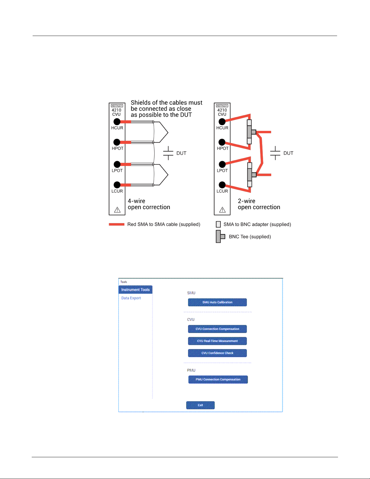
1. Make the connections to the CVU, as shown in the following figure. For remote (4-wire) sensing,
the shields of the four SMA cables must be connected as close as possible.
Figure 8: Connections for open connection compensation CVU
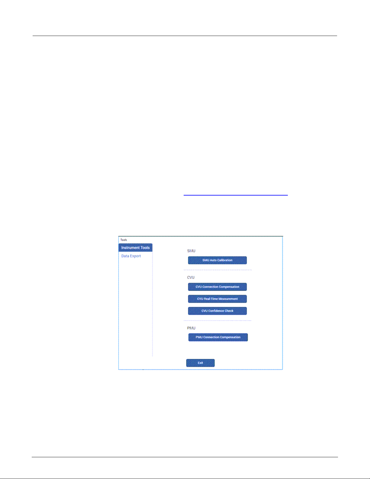
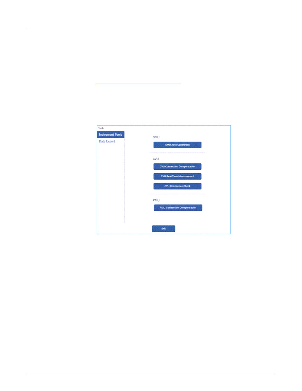
2. In Clarius, select Tools. The Clarius Tools dialog opens.
Figure 9: Clarius Tools dialog
4200A-CVU-900-01 Rev. B March 2023 2-9
Page 21

Section
User's Manual
2: Connections Model 4200A-SCS Capacitance-Voltage Unit (CVU)
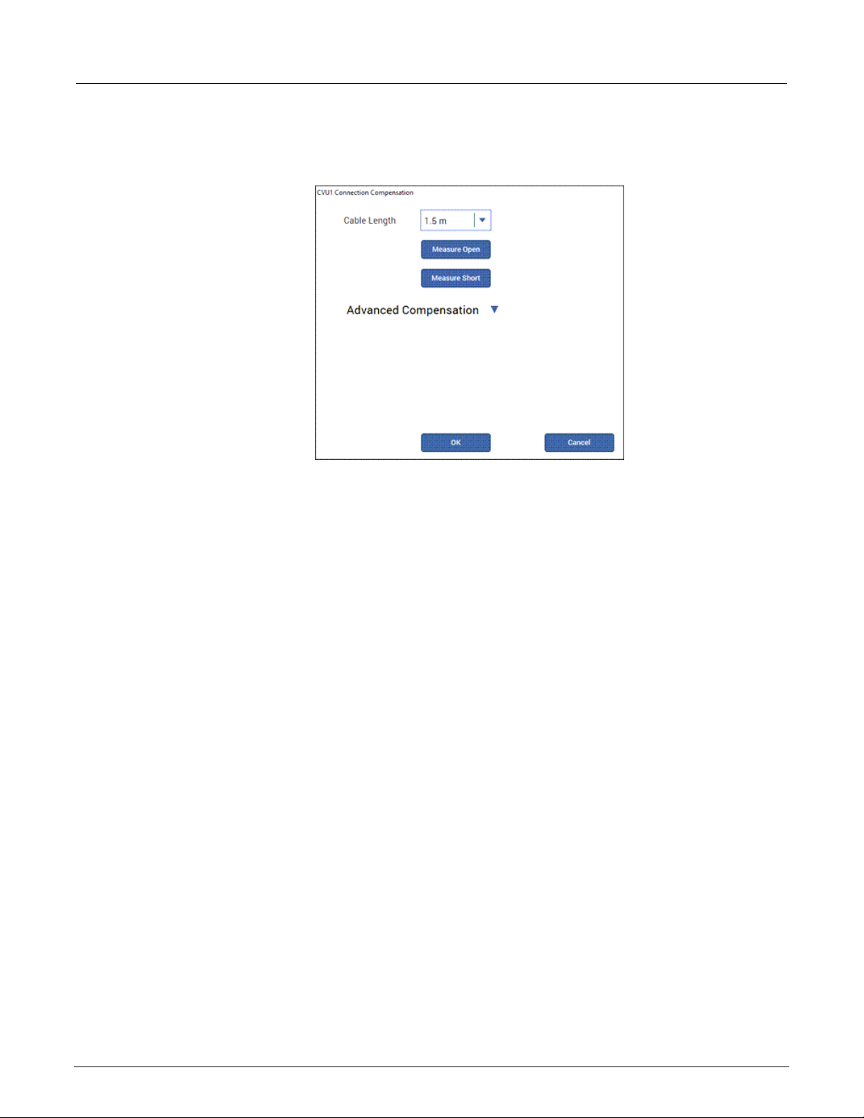
3. Select CVU Connection Compensation.
Figure 10: CVU Connection Compensation dialog
4. Select the cable length. You can select:
0 m: Use if measurements are made at the terminals of the CVU (no cables).
1.5 m: Use with the standard red SMA cables (part number CA-447A) that are supplied with
the CVU.
3 m: Use with the red SMA cables (part number CA-446) that are supplied with the
4200-CVU-PROBER-KIT. You can also use this setting if you are using a switching matrix.
Custom: Cable length coefficients are measured by the user using the Measure Custom
Cable Length option under Advanced Compensation.
5. If you selected Custom cable length, select Advanced Compensation and select Measure
Custom Cable Length. Follow the on-screen instructions.
6. If you are using a switching matrix, close the matrix switches that connect the CVU to the open.
Refer to “Using Switch Matrices” in Model 4200A-SCS Prober and External Instrument Control.
7. In the Clarius CVU Connection Compensation dialog, select Measure Open.
8. Follow the instructions.
9. Select OK.
2-10 4200A-CVU-900-01 Rev. B March 2023
Page 22
Model 4200A
Connections
-SCS Capacitance-Voltage Unit (CVU) User's Manual Section 2:
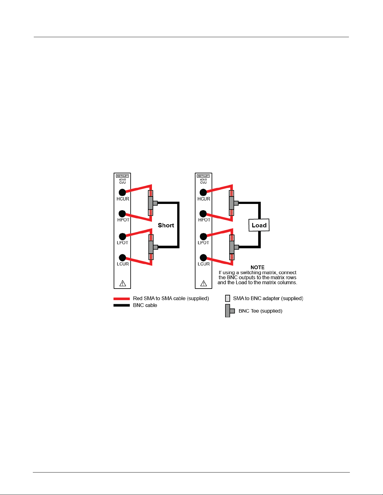
Generate short connection compensation data
Short connection compensation is usually done to offset correction for large capacitances.
Short compensation is done by connecting all the CVU terminals directly together. A known short is
connected to the CVU terminals through all the cables, adapters, and probes that may be in the test
circuit. You can make a short at the wafer level by shorting all probes together.
To generate short connection compensatio n data:
1. Make the connections to the CVU, as shown in the following figure. For remote (4-wire) sensing,
the shields of the four SMA cables must be connected.
Figure 11: Connections for short and load connection compensation
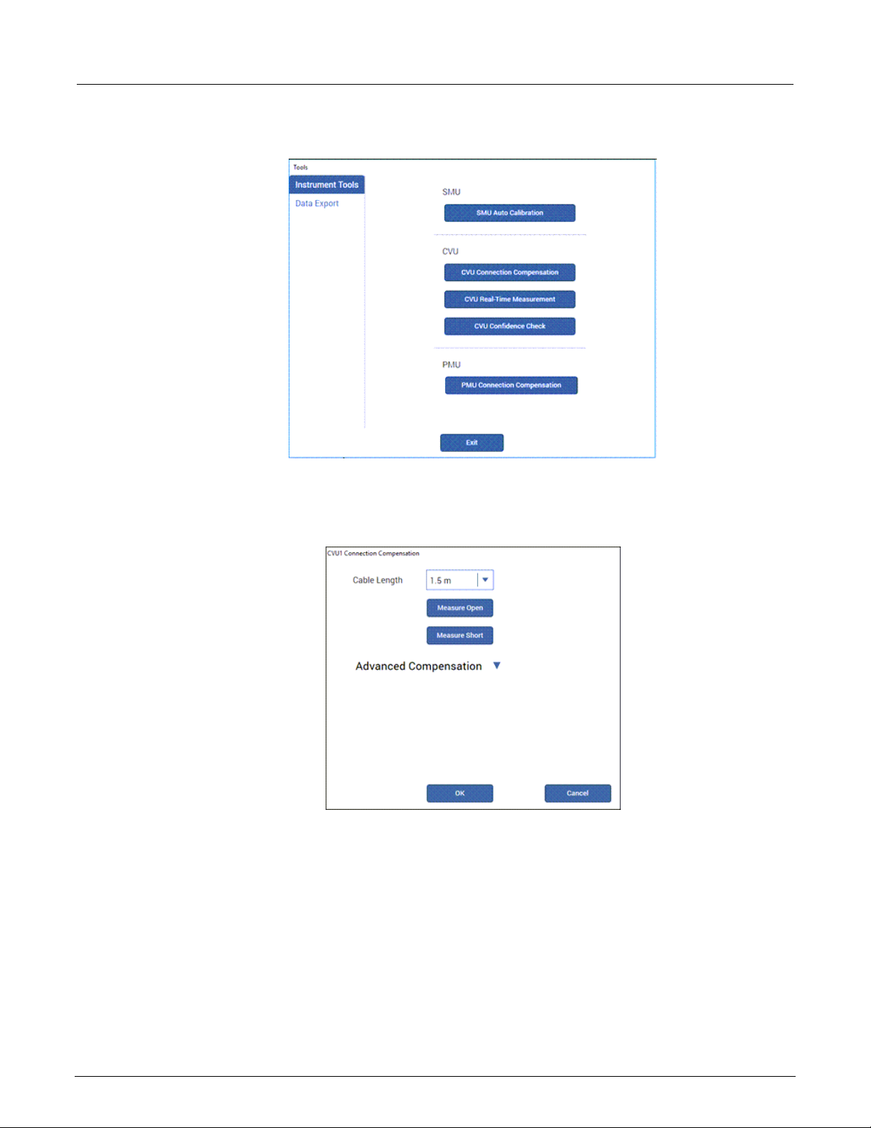
2. In Clarius, select Tools. The Clarius Tools dialog opens.
4200A-CVU-900-01 Rev. B March 2023 2-11
Page 23
Section
User's Manual
2: Connections Model 4200A-SCS Capacitance-Voltage Unit (CVU)
Figure 12: Clarius Tools dialog
3. Select CVU Connection Compensation.
Figure 13: CVU Connection Compensation dialog
4. Select the cable length. You can select:
0 m: Use if measurements are made at the terminals of the CVU (no cables).
1.5 m: Use with the standard red SMA cables (part number CA-447A) that are supplied with
the CVU.
3 m: Use with the red SMA cables (part number CA-446) that are supplied with the
4200-CVU-PROBER-KIT. You can also use this setting if you are using a switching matrix.
Custom: Cable length coefficients are measured by the user using the Measure Custom
Cable Length option under Advanced Compensation.
2-12 4200A-CVU-900-01 Rev. B March 2023
Page 24
Model 4200A
Connections
-SCS Capacitance-Voltage Unit (CVU) User's Manual Section 2:
5. If you selected Custom cable length, select Advanced Compensation and select Measure
Custom Cable Length. Follow the on-screen instructions.
6. If you are using a switching matrix, close the matrix switches that connect the CVU to the open.
Refer to “Using Switch Matrices” in Model 4200A-SCS Prober and External Instrument Control.
7. In the Clarius CVU Connection Compensation dialog, select Measure Short.
8. Follow the instructions.
9. Select OK.
Generate load connection compensation data
Loads are reference resistors, typically 50 or 100 Ω or less, that must be resistive and constant over
the entire frequency range (1 kHz to 10 MHz). A load is connected to the output terminals using all
the cables, adapters, probes, and other hardware in the test circuit.
To generate load correction data:
1. Make the connections to the CVU. See “Test connections for a switching matrix (on page 2-5
the Model 4200A-SCS Capacitance-Voltage Unit (CVU) User's Manual.
2. In Clarius, select Tools. The Clarius Tools dialog opens.
Figure 14: Clarius Tools dialog
)” in
4200A-CVU-900-01 Rev. B March 2023 2-13
Page 25
Section
User's Manual
2: Connections Model 4200A-SCS Capacitance-Voltage Unit (CVU)
3. Select CVU Connection Compensation.
Figure 15: CVU Connection Compensation dialog
4. Select the cable length. You can select:
0 m: Use if measurements are made at the terminals of the CVU (no cables).
1.5 m: Use with the standard red SMA cables (part number CA-447A) that are supplied with
the CVU.
3 m: Use with the red SMA cables (part number CA-446) that are supplied with the
4200-CVU-PROBER-KIT. You can also use this setting if you are using a switching matrix.
Custom: Cable length coefficients are measured by the user using the Measure Custom
Cable Length option under Advanced Compensation.
5. If you selected Custom cable length, select Advanced Compensation and select Measure
Custom Cable Length. Follow the on-screen instructions.
6. If you are using a switching matrix, close the matrix switches that connect the CVU to the open.
Refer to “Using Switch Matrices” in Model 4200A-SCS Prober and External Instrument Control.
7. If it is not open, select Advanced Compensation.
8. In Measure Load, enter the value of the load in ohms.
9. Select Measure Load.
10. Follow the instructions.
11. Select OK.
2-14 4200A-CVU-900-01 Rev. B March 2023
Page 26

Model 4200A
Connections
-SCS Capacitance-Voltage Unit (CVU) User's Manual Section 2:
Compensation data
You can view the compensation data. Clarius lists R and jX compensation values for every test
frequency and measurement range for open, short, and load.
To view the data generated by connection compensation:
1. In Clarius, select Tools.
2. Select CVU Connection Compensation.
3. Select Advanced Compensation.
4. Next to View Compensation Data, select the data you would like to display: Open, Short, or
Load.
5. Select View Compensation Data.
6. Select the HI tab to review the high side values.
7. Select the LO tab to review the low side values.
Figure 16: Open compensation values example
Enable compensation
To use the values generated by connection compensation, you need to enable compensation for
each test.
When compensation is enabled, the most recently acquired CVU compensation data is applied.
Compensation values can be gathered using the CVU Connection Compensation option in Tools or
through actions and user modules.
4200A-CVU-900-01 Rev. B March 2023 2-15
Page 27
Section
User's Manual
2: Connections Model 4200A-SCS Capacitance-Voltage Unit (CVU)
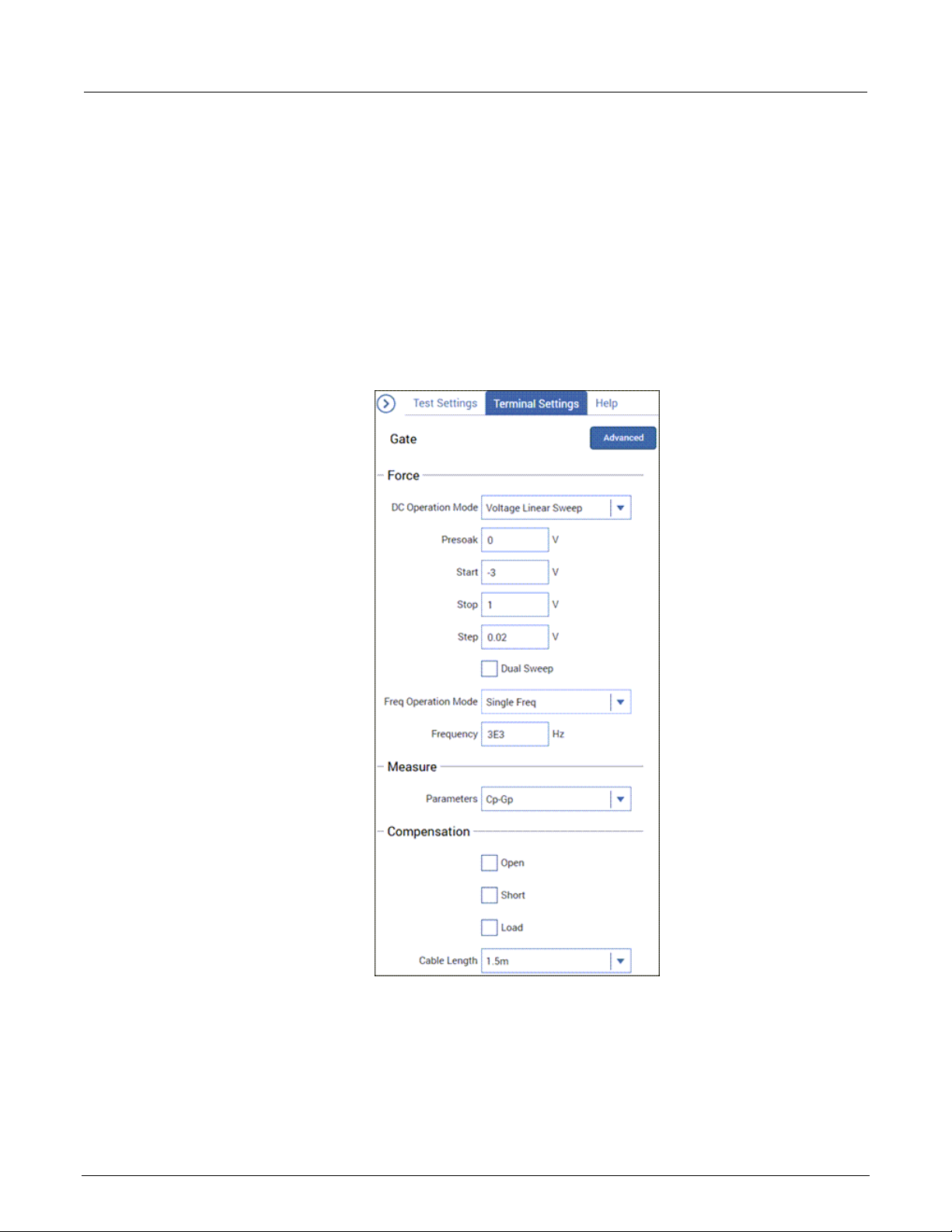
To enable compensation:
1. Select the test from the project tree.
2. Select Configure.
3. Select the terminal in the center pane.
4. In the right pane, select Terminal Settings.
5. Under Compensation, select the types of compensation as needed.
6. Make sure Cable Length is the same as the setting that was used in the Tools > CVU
Connection Compensation dialog to generate connection compensation data.
Figure 17: Enable connection compensation
2-16 4200A-CVU-900-01 Rev. B March 2023
Page 28

Model 4200A
Connections
-SCS Capacitance-Voltage Unit (CVU) User's Manual Section 2:
ABB unbalance errors
The CVU uses the autobalancing bridge (ABB) technique to achieve accurate impedance
measurements. ABB creates a virtual ground at the DUT to minimize measurement error. Every CVU
measurement is made with ABB active. The ABB always attempts to lock the low side of the DUT to
virtual ground.
If the ABB fails to lock, the measurement is made, but may be out of specification. If this occurs, the
returned data is flagged and shown in yellow on a blue background on the Analyze sheet.
The most common reasons that ABB fails to lock are:
• The cable lengths on the CVU terminals are not the same
• HPOT or LPOT terminals were disconnected
• Excessive noise on the LPOT terminal
• High frequency sources
• Physical cable lengths do not match the cable length set in Clarius
• Improperly torqued SMA cables
• Sub-optimal I
RANGE
setting
• Too much parasitic load on the low side of the DUT
You can use CVU Confidence Check to help troubleshoot ABB errors. Refer to
and short check (on page 2-18) for instructions on performing a confidence check.
CVU Confidence Check
CVU Confidence Check is a diagnostic tool that allows you to check the integrity of open and short
connections and connections to a device under test (DUT). When the CVU is connected to the DUT,
the Confidence Check displays the measured readings in real time in the Messages area of Clarius.
An open or short confidence check makes a measurement on the high and the low sides of the
test circuit.
The open check is not compatible with the 4200A-CVIV Bias Tee configurations.
To get the best results from a confidence check:
• Use the red CA-446A or CA-447A cables or equivalent.
Run an open check
• If applicable, make sure the prober chuck is connected.
• If you are using a switching matrix, make sure all channels are closed.
4200A-CVU-900-01 Rev. B March 2023 2-17
Page 29
Section
User's Manual
2: Connections Model 4200A-SCS Capacitance-Voltage Unit (CVU)
Run an open check and short check
To run a CVU confidence check:
1. If you are using a switching matrix, connect the switching matrix to the CVU and DUT or the short
as explained in Test connections for a switching matrix (on page 2-5
2. For the short check, close the matrix switches to connect the CVU to the DUT or short. For the
open check, also close the matrix switches, but lift the probes or disconnect the DUT.
3. In Clarius, select Tools. The Clarius Tools dialog opens.
Figure 18: Clarius Tools dialog
).
4. Select CVU Confidence Check.
5. Select Check Open or Check Short.
2-18 4200A-CVU-900-01 Rev. B March 2023
Page 30
Model 4200A
ions
-SCS Capacitance-Voltage Unit (CVU) User's Manual Section 2: Connect
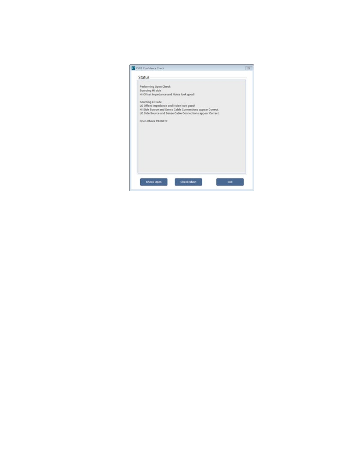
Figure 19: CVU Confidence Check dialog
6. Follow the instructions and select OK.
When the check is complete, the dialog displays the results of the test. If the test failed, the results
include suggestions for troubleshooting.
CVU Real-Time Measureme nt
The CVU Real-Time Measurement provides a direct real-time user interface to the CVU to help you
set up and debug your system. For example, you can use it to confirm that contact has been made
with the pads on a wafer. The measurements are independent of the open and short
confidence checks.
To make real-time measurements:
1. In Clarius, select Tools. The Clarius Tools dialog opens.
4200A-CVU-900-01 Rev. B March 2023 2-19
Page 31

Section
User's Manual
2: Connections Model 4200A-SCS Capacitance-Voltage Unit (CVU)
Figure 20: Clarius Tools dialog
2. Select Instrument Tools.
Figure 21: Real-Time Measurement dialog
3. Select CVU Real-Time Measurem en t.
4. Select the parameters for which you want to return results.
5. Set the Speed, AC Drive Conditions, and DC Bias Conditions for the conditions you want to test.
6. Select Run. The results for the selected parameters are displayed at the top of the dialog.
2-20 4200A-CVU-900-01 Rev. B March 2023
Page 32

CVU test settings ................................................................... 3-32
Section 3
Setting up CVUs in Clarius
In this section:
CVU project example ............................................................... 3-1
Selecting the DC Operation Mode ............................................ 3-5
Selecting the Freq Operation Mode ......................................... 3-6
Making additional test settings ................................................. 3-8
Typical test setups with timing diagrams .................................. 3-9
Force-measure timing ............................................................ 3-22
CVU - all terminal parameters ................................................ 3-23
CVU Terminal Settings Advanced settings and circuits ......... 3-30
CVU project examp le
The following example shows you how to use the 4210-CVU or 4215-CVU in a project to make a
capacitance measurement.
The example assumes you have a CVU connected to a test fixture as described in
connections to a DUT (on page 2-3).
In this test, you sweep the dc bias from −5 V to 5 V in 0.2 V steps, with a 1 MHz capacitance
measurement made at each step.
Select a project
Select a project:
1. Start Clarius.
2. Run Connection compensation (on page 2-8
the connections.
3. Choose Select.
4. Select Projects to display the Project Library in the center pane.
5. Search for demo. The Demo Project is displayed, as shown in the following figure.
Typical CVU test
) to correct for offset and gain errors caused by
Page 33

Section
User's Manual
3: Setting up CVUs in Clarius Model 4200A-SCS Capacitance-Voltage Unit (CVU)
Figure 22: Demo Project selected
6. Select Create. You are prompted to replace the existing project.
7. Select Yes. The project is displayed in the project tree.
Figure 23: Demo Project (default) in the project tree
3-2 4200A-CVU-900-01 Rev. B March 2023
Page 34

Model 4200A
Setting up CVUs in Clarius
-SCS Capacitance-Voltage Unit (CVU) User's Manual Section 3:
Configure the test
This example uses the cv-cap test, which measures the capacitance as a function of a linear voltage
sweep of a capacitor.
Configure the cv-cap test:
1. In the project tree, select the cv-cap test.
2. Select Configure. The key parameters are displayed in the center pane.
Figure 24: cv-cap key parameters
3. Verify the settings for CVH1:
Operation Mode: Voltage Linear Sweep
Start: −5 V
Stop: 5 V
Step: 0.2 V
Frequency Operation Mode: Single Freq
Frequency: 1 MHz
Run the test and review results
To run the cv-cap test and review the results:
1. Select Run.
2. Select Analyze. The test results are shown as data in a spreadsheet and on the graph, as shown
in the figure below.
3. To export the data, select Save Data.
4200A-CVU-900-01 Rev. B March 2023 3-3
Page 35

Section
User's Manual
3: Setting up CVUs in Clarius Model 4200A-SCS Capacitance-Voltage Unit (CVU)
4. To save the information in the Run sheet, select Save Sheet. The information is saved in a
®
Microsoft
Excel® spreadsheet format.
5. To save the information in the graph, select the Graph File Format and select Save Graph1.
The graph is saved into the selected file type.
Note that the extracted NOISE parameter is displayed on the graph.
For information on changing how the graph is displayed, refer to “Change the graph settings” in the
Model 4200A-SCS Clarius User's Manual.
Figure 25: cv-cap test results
3-4 4200A-CVU-900-01 Rev. B March 2023
Page 36

Model 4200A
Setting up CVUs in Clarius
-SCS Capacitance-Voltage Unit (CVU) User's Manual Section 3:
Selecting the DC Ope r a t ion Mo de
DC Operation Mode selects the most common settings for the selected test type. Selecting the
appropriate mode simplifies terminal and test configuration. The following topics describe the
operation modes that are available when a CVU is selected as the instrument.
For descriptions of the parameters that you can set for the operation modes, refer to
terminal parameters (on page 3-23).
Voltage Bias
The Voltage Bias operation mode maintains a selected constant-voltage state at the terminal.
Voltage Linear Sweep
When you select the Voltage Linear Sweep operation mode, the test increments through a series of
constant voltage steps. You define the start and stop voltages and the voltage size between each
step. An example is shown in the following figure.
CVU - all
Figure 26: Example linear sweep
The voltage sweep generates parametric curve data that is recorded in the Analyze pane.
Voltage List Sweep
The Voltage List Sweep operation mode allows you to customize the voltage values for each step of
the sweep. List Sweeps allow you to make measurements only at selected forced voltages. For
example, they allow you to skip unimportant measurement points or to synthesize a custom sweep
that is based on a special mathematical equation. You can also use list sweeps to make pulsed
measurements to avoid overheating of sensitive devices. The following figure illustrates a possible
list sweep.
4200A-CVU-900-01 Rev. B March 2023 3-5
Page 37

Section
User's Manual
3: Setting up CVUs in Clarius Model 4200A-SCS Capacitance-Voltage Unit (CVU)
The voltage list sweep generates parametric curve data that is recorded in the Analyze pane.
Voltage Step
The Voltage Step operation mode increments through evenly-spaced, constant voltage steps over a
range that you specify. The time interval for each step is determined automatically by the time
required to complete a sweep.
Figure 27: Example voltage list sweep
For each step, parametric curve data is generated. The data is recorded in the Analyze pane.
DC Gnd operation mode - CVU
Automatically selected for the CVL terminal.
Selecting the Freq Operation Mode
The Frequency Operation Mode selects the most common settings for the selected test type.
Selecting the appropriate mode simplifies terminal and test configuration.
If you have a 4210-CVU, you can select Single Freq, Freq Linear Sweep, or Freq Step. If you have a
4215-CVU, you can also select Freq Log Sweep or Freq List Sweep.
The following topics describe these operation modes.
Frequency Single Freq
The CVU makes a single frequency reading.
Frequency Linear Sweep
When performing a frequency sweep, the CVU steps through all the frequency points from start to
stop at the frequency intervals set by the step.
3-6 4200A-CVU-900-01 Rev. B March 2023
Page 38

Model 4200A
Setting up CVUs in Clarius
-SCS Capacitance-Voltage Unit (CVU) User's Manual Section 3:
Freq Log Sweep
This sweep is similar to the linear sweep except that the steps are done on a logarithmic scale.
Freq List Sweep
The Freq List Sweep operation mode allows you to customize the voltage values for each step of the
sweep. List Sweeps allow you to make measurements only at selected frequencies. For example,
they allow you to skip unimportant measurement points or to synthesize a custom sweep that is
based on a special mathematical equation.
Freq Step
When the Freq Step operation mode is selected, the CVU sweeps through all the frequency points
from start to stop for each dc step.
Figure 28: Frequency sweep - DC step operation mode
For example, if the:
• Start frequency is 800 kHz
• Stop frequency is 3 MHz
• The dc start value is −1
• Stop value is 1
• Step value is 0.5
The CVU sweeps through the frequency points 800 kHz, 900 kHz, 1 MHz, 2 MHz, and 3 MHz for dc
biases −1 V, −0.5 V, 0 V, 0.5 V, and 1 V.
4200A-CVU-900-01 Rev. B March 2023 3-7
Page 39

Section
User's Manual
3: Setting up CVUs in Clarius Model 4200A-SCS Capacitance-Voltage Unit (CVU)
When this test is run, the following sequence occurs:
1. The dc source goes to the Presoak voltage.
2. After the hold time (set in the Test Settings), dc bias goes to the Start voltage.
3. After the delays, the CVU makes a measurement for the Start Frequency point. The ac signal is
applied before the start of the measurement.
4. The CVU sweeps through the frequency points until it reaches the Stop Frequency point.
5. The dc bias goes to the next voltage as defined by the Step value.
6. Steps 4 and 5 are repeated until the dc bias reaches the Stop value.
Making additional test settings
You can refine your test settings using the Test Settings tab in the right pane.
Figure 29: CVU Test Settings pane
From the Test Settings pane, you can open additional options by selecting Advanced.
3-8 4200A-CVU-900-01 Rev. B March 2023
Page 40

Model 4200A
Setting up CVUs in Clarius
-SCS Capacitance-Voltage Unit (CVU) User's Manual Section 3:
Figure 30: CVU Advanced Test Settings Pane
Refer to CVU Test Settings (on page 3-32) for descriptions of the test settings.
Typical test setups with timing diag r ams
The following topics describe typical test setups with the related timing diagrams.
DC bias function and sweep characteristics
The ac test signal can be biased with a static dc level (−30 V to +30 V), or a voltage sweep (up or
down). You can also perform a frequency sweep (up or down).
The following figure shows an example of dc bias waveform. In this example, the dc bias is set to 0 V,
but you can set it to any valid dc bias level. You specify the number of measurements to make.
Figure 31: DC Bias waveform (example)
4200A-CVU-900-01 Rev. B March 2023 3-9
Page 41

Section
User's Manual
3: Setting up CVUs in Clarius Model 4200A-SCS Capacitance-Voltage Unit (CVU)
The following figure shows an example of dc voltage sweep. You specify the start voltage, stop
voltage, and step voltage. The number of measure points is calculated by the CVU.
Figure 32: DC voltage sweep (example)
The following figure shows an example of a frequency sweep. You specify the start frequency and the
stop frequency. The CVU calculates the number of measure points.
Figure 33: Frequency sweep example
If you are setting up a voltage list sweep, you specify the voltage levels for the sweep.
If you are setting up a voltage step frequency sweep, the sweep includes voltage stepping. A
frequency sweep is performed for every voltage step point.
If you are setting up a frequency step voltage sweep, the sweep includes frequency stepping. A
voltage sweep is performed for every frequency point.
The following examples are examples of these setups in Clarius.
3-10 4200A-CVU-900-01 Rev. B March 2023
Page 42

Model 4200A
Setting up CVUs in Clarius
-SCS Capacitance-Voltage Unit (CVU) User's Manual Section 3:
CVU using voltage bias
Make the following Test Settings for a dc bias with a single frequency. This sweep measures CP-Gp.
• Speed: Normal
• Report Timestamps: Selected
• Mode: Sampling
• Interval: 0.25 s
• Number of Samples: 10
• Hold Time: 1 s
Make the following Terminal Settings for CVH1:
• DC Operation Mode: Voltage Bias
• Presoak: 5 V
• DC Bias: 1 V
• Frequency Operation Mode: Single Freq
• Frequency: 100000 Hz
• Parameters: Cp-Gp
• Compensation as needed
When this test is run, the following force-measure sequence occurs:
1. The dc source goes to the Presoak voltage of 5 V for the hold time (1 s).
2. The dc source goes to the dc bias voltage of 1 V.
3. After the built-in system delay and interval (0.25 s), the CVU makes a measurement. The ac test
signal is applied just before the start of the measurement. The ac drive is turned off after the
measurement is completed. This step is repeated for every sample.
Figure 34: CVU Voltage Bias output
4200A-CVU-900-01 Rev. B March 2023 3-11
Page 43

Section
User's Manual
3: Setting up CVUs in Clarius Model 4200A-SCS Capacitance-Voltage Unit (CVU)
CVU using voltage sweep
Make the following Test Settings:
• Speed: Normal
• Report Timestamps: Selected
• Mode: Sweeping
• Sweep Delay: 0.1 s
• Hold Time: 1 s
For this test, make the following Terminal Settings for CVH1:
• DC Operation Mode: Voltage Linear Sweep
• Presoak: 5 V
• Start: 5 V
• Stop: 3 V
• Step: 1 V
• Frequency Operation Mode: Single Freq
• Frequency: 100000 Hz
• Dual sweep: Selected
• Parameters: Cp-Gp
• Compensation as needed
The following figure shows the Advanced terminal settings for a voltage linear sweep. This sweep
measures Cp-Gp.
Figure 35: 4215-CVU Voltage Linear Sweep
3-12 4200A-CVU-900-01 Rev. B March 2023
Page 44

Model 4200A
Setting up CVUs in Clarius
-SCS Capacitance-Voltage Unit (CVU) User's Manual Section 3:
When this test is run, the following force-measure sequence occurs:
1. The dc source goes to the presoak voltage of −5 V for the hold time.
2. The dc bias voltage goes to the first step of the sweep (1 V).
3. After the built-in system delay and sweep delay, the 4210-CVU or 4215-CVU makes a
measurement. The ac test signal is applied before the start of the measurement. The ac drive is
turned off after the measurement is made.
4. Steps 2 and 3 are repeated for the 2 V and 3 V dc bias voltage steps. The sweep delay repeats at
the beginning of each subsequent step.
The sweep delay and hold time are set from the Test Settings.
To do a dual CVU voltage sweep, select Du al Sweep in the Terminal Settings pane. If Dual Sweep is
selected, after the stop step is measured, the sweep continues in the reverse direction. For the
settings shown in the above figure, the dual sweep steps through 1 V, 2 V, 3 V, 3 V, 2 V, and 1 V.
The number of measurements doubles to six.
Figure 36: CVU voltage sweep output
CVU using voltage list sweep
Make the following Test Settings:
• Speed: Normal
• Report Timestamps: Selected
• Mode: Sweeping
• Sweep Delay: 0.1 s
• Hold Time: 1 s
4200A-CVU-900-01 Rev. B March 2023 3-13
Page 45

Section
User's Manual
3: Setting up CVUs in Clarius Model 4200A-SCS Capacitance-Voltage Unit (CVU)
For this test, make the following Terminal Settings for CVH1:
• DC Operation Mode: Voltage List Sweep
• Presoak: 5 V
• Voltage: Enter Values in List
• Frequency Operation Mode: Single Freq
• Frequency: 100000 Hz
• AC Drive Signal: 30 mV RMS
• Parameters: Cp-Gp
• Compensation as needed
This figure shows an example of the Advanced Terminal Settings dialog when the DC Operation
Mode is set to Voltage List Sweep, the Freq Operation Mode is set to Single Freq, and the Measure
Parameters are set to measure Cp-Gp.
Figure 37: CVU Voltage List Sweep
3-14 4200A-CVU-900-01 Rev. B March 2023
Page 46

Model 4200A
Setting up CVUs in Clarius
-SCS Capacitance-Voltage Unit (CVU) User's Manual Section 3:
When this test is run, this sequence occurs:
1. The dc source goes to the presoak voltage for the hold time. Typically, the presoak voltage is at
the same potential as the first point in the sweep to allow the device to charge up to equilibrium
before measurements begin.
2. The dc bias goes to the first sweep point voltage.
3. After the built-in system delay and sweep delay, the 4210-CVU or 4215-CVU makes a
measurement. The ac test signal is applied just before the start of the measurement. The ac drive
is turned off after the measurement is completed.
4. Steps 2 and 3 are repeated for remaining dc bias voltages. The sweep delay repeats at the
beginning of each step.
Figure 38: CVU Voltage List Swee p o utp u t
CVU using a dc voltage bias and a frequency sweep
Make the following Test Settings:
• Speed: Normal
• Report Timestamps: Selected
• Mode: Sweeping
• Hold Time: 1 s
• Sweep Delay: 0.1 s
4200A-CVU-900-01 Rev. B March 2023 3-15
Page 47

Section
User's Manual
3: Setting up CVUs in Clarius Model 4200A-SCS Capacitance-Voltage Unit (CVU)
For this test, make the following Terminal Settings for CVH1:
• DC Operation Mode: Voltage Bias
• Presoak: 5 V
• DC Bias: 1V
• Frequency Operation Mode: Freq Linear Sweep
• Start Frequency: 100000 Hz
• Stop Frequency: 300000 Hz
• Step Frequency: 100000 Hz
• AC Drive Signal: 15 mV RMS
• Parameters: Cp-Gp
• Compensation as needed
The following shows an example of the Advanced Terminal Settings dialog when the DC Operation
Mode is set to Voltage Bias and the Freq Operation Mode is set to Freq Linear Sweep. Note that this
example also applies to the Freq Log Sweep and Freq List Sweep modes of the 4215-CVU.
Figure 39: DC Voltage Bias and Freq Linear Sweep
3-16 4200A-CVU-900-01 Rev. B March 2023
Page 48

Model 4200A
Setting up CVUs in Clarius
-SCS Capacitance-Voltage Unit (CVU) User's Manual Section 3:
When this test is run, the following force-measure sequence occurs:
1. The dc source goes to the Presoak voltage of 5 V for the hold time.
2. The dc bias goes to 1 V for the system delay and sweep delay times and remains on during the
frequency sweep.
3. The 4210-CVU or 4215-CVU makes a measurement for the first frequency point (100 kHz). The
ac test signal is applied before the start of the measurement. The ac drive is turned off after the
measurement is made.
4. Step 3 is repeated for the other frequency points. The system delay and sweep delay are
repeated for each subsequent measurement.
The sweep delay and hold time are set in the Test Settings pane.
Figure 40: CVU Frequency Sweep (bias) output
CVU frequency sweep - DC step
Make the following Test Settings:
• Speed: Normal
• Report Timestamps: Selected
• Mode: Sweeping
• Sweep Delay: 0.1 s
• Hold Time: 1 s
4200A-CVU-900-01 Rev. B March 2023 3-17
Page 49

Section
User's Manual
3: Setting up CVUs in Clarius Model 4200A-SCS Capacitance-Voltage Unit (CVU)
For this test, make the following Terminal Settings for CVH1:
• DC Operation Mode: Voltage Step
• Presoak: -1 V
• Start: 0 V
• Stop: 2 V
• Step: 1 V
• Frequency Operation Mode: Freq Linear Sweep
• Start Frequency: 100000 Hz
• Stop Frequency: 200000 Hz
• Step Frequency: 100000 Hz
• AC Drive Signal: 30 mV RMS
• Parameters: Cp-Gp
• Compensation as needed
The following figures show examples of the Advanced Terminal Settings dialog for a test set to
Voltage Step and Frequency Linear Sweep Note that this example also applies to Freq Log Sweep
and Freq List Sweep modes of the 4215-CVU. This test is set to measure Cp-Gp.
Figure 41: Voltage Step and Freq Linear Sweep
3-18 4200A-CVU-900-01 Rev. B March 2023
Page 50

Model 4200A
Setting up CVUs in Clarius
-SCS Capacitance-Voltage Unit (CVU) User's Manual Section 3:
When this test is run, the following source-measure sequence occurs:
1. The dc source goes to the presoak voltage of −1 V.
2. After the hold time, dc bias goes to 0 V.
3. After the system delay and the sweep delay, the 4210-CVU or 4215-CVU makes a measurement
for the 100 kHz frequency point. The ac signal is applied before the start of the measurement.
4. After another system delay and sweep delay, a measurement is made for the 200 kHz
frequency point.
5. The dc bias goes to 1 V.
6. Steps 3 and 4 are repeated.
7. The dc bias goes to 2 V.
8. Steps 3 and 4 are repeated.
The sweep delay and hold time are set in the Test Settings pane for the test.
Figure 42: CVU Frequency Sweep (step) output
CVU voltage linear sweep - frequency step
Make the following Test Settings:
• Speed: Normal
• Report Timestamps: Selected
• Mode: Sampling
• Sweep Delay: 0.1 s
• Hold Time: 1 s
4200A-CVU-900-01 Rev. B March 2023 3-19
Page 51

Section
User's Manual
3: Setting up CVUs in Clarius Model 4200A-SCS Capacitance-Voltage Unit (CVU)
For this test, make the following Terminal Settings for CVH1:
• DC Operation Mode: Voltage Linear Sweep
• Presoak: -1 V
• Start: 0 V
• Stop: 2 V
• Step: 1 V
• Frequency Operation Mode: Freq Step
• Start Frequency: 100000 Hz
• Stop Frequency: 200000 Hz
• Step Frequency: 100000 Hz
• AC Drive Signal: 30 mV RMS
• Parameters: Cp-Gp
• Compensation as needed
The following figures show examples of the Advanced Terminal Settings dialog for a test set to DC
Sweep - Frequency Step for the 4210-CVU and 4215-CVU. The test is set to measure Cp-Gp.
Figure 43: 4210-CVU Voltage Linear Sweep - Freq Step Advanced Terminal Settings
3-20 4200A-CVU-900-01 Rev. B March 2023
Page 52

Model 4200A
Setting up CVUs in Clarius
-SCS Capacitance-Voltage Unit (CVU) User's Manual Section 3:
Figure 44: 4215-CVU Voltage Linear Sweep and Freq Step Advanced Terminal Settings
When this test is run, the following source-measure sequence occurs:
1. The dc source goes to the presoak voltage of −1.
2. After the hold time, dc bias goes to 0 V.
3. The 100 kHz frequency step point is set. The ac signal is applied before the start of
the measurement.
4. After the system delay and sweep delay, a measurement is made for the 0 V dc sweep point.
5. After another system delay and sweep delay, a measurement is made for the next dc sweep point.
This is repeated until the last sweep point measurement is made.
6. The frequency goes to 200 kHz.
7. Steps 4 and 5 are repeated.
The sweep delay and hold time are set in the Test Settings pane for the test.
4200A-CVU-900-01 Rev. B March 2023 3-21
Page 53

Section
User's Manual
3: Setting up CVUs in Clarius Model 4200A-SCS Capacitance-Voltage Unit (CVU)
Figure 45: CVU DC Sweep - Freq Step output
Force-measure timing
Timing diagrams for the force-measure process for bias and sweep functions are shown in the next
two topics.
Bias function timing
You can apply dc voltage bias to the DUT (±30 V).
Timing for the force-measure process for a bias function is shown in the following figure. When the
test is started, the following timing sequence takes place:
1. The dc source outputs the presoak voltage for the hold time.
2. The dc source goes to the dc bias voltage.
3. After the built-in system delay and time intervals, the CVU makes a measurement. The ac test
signal is applied just before the start of the measurement. The ac drive is turned off after the
measurement is completed. This step is repeated for every measurement.
Figure 46: Force-measure timing
3-22 4200A-CVU-900-01 Rev. B March 2023
Page 54

Model 4200A
Setting up CVUs in Clarius
-SCS Capacitance-Voltage Unit (CVU) User's Manual Section 3:
Sweep function timing
Force-measure timing for a sweep function is similar to the timing for a bias function (shown in Bias
function timing (on page 3-22)), with the following differences:
• The hold time is repeated at the beginning of each subsequent sweep step.
• A sweep delay is used in place of the interval.
CVU - all termin al parameters
When you select All Parameters, the Configure pane displays all available parameters for the test
that is selected in the project tree.
Parameter descriptions are provided in the following sections.
Presoak
Type a presoak voltage of −30 V to +30 V.
Start
The voltage source level at which the sweep starts.
Stop
The voltage source level at which the sweep stops.
Step (voltage sweep)
The voltage size of each step of the sweep. The source level changes in equal steps of this size from
the start level to the stop level. A measurement is made at each source step (including the start and
stop levels).
Clarius never steps the force voltage beyond the value specified by the stop parameter, even if you
specify a step value that is larger than the stop value.
Use a step value that does not result in a fractional number of points. If the point is fractional, the step
value is forced to a value that results in a whole number of points. To calculate the points:
The points are rounded to the nearest value.
4200A-CVU-900-01 Rev. B March 2023 3-23
Page 55

Section
User's Manual
3: Setting up CVUs in Clarius Model 4200A-SCS Capacitance-Voltage Unit (CVU)
For example, if Start = 0 V, Stop = 5 V, and Step = 0.6 V:
In this case, the Step value is forced to 0.625 V, which results in a point value of 9.333, which is
rounded to 9. The instrument forces nine voltages at 0 V, 0.625 V, 1.25 V, 1.875 V, 2.5 V, 3.125 V,
3.75 V, 4.375 V, and 5 V.
List Values
Select Enter Value s to open a dialog in which you can type the current or voltage level for each step
of the sweep in the rows. You can type any valid instrument current or voltage.
You can select a value or multiple values in the list and copy, cut, or delete them. Use Paste to add
values that you copied or cut to a new location in the list.
You cannot have blank rows in between values.
You can use the Ctrl key plus mouse selections to pick selected rows, then use the buttons to copy,
cut, or delete those rows. Note that when you paste the rows, any skipped rows are ignored (there will
be no blank rows).
You can use the Shift key plus mouse selections to pick a range of rows. When you paste the rows,
any blank rows are ignored.
Freq Operation Mode
The Frequency Operation Mode selects the most common settings for the selected test type.
Selecting the appropriate mode simplifies terminal and test configuration.
If you have a 4210-CVU, you can select Single Freq, Freq Linear Sweep, or Freq Step. If you have a
4215-CVU, you can also select Freq Log Sweep or Freq List Sweep.
Start (Freq Operation Mode)
The frequency at which the sweep starts.
Stop (Freq Operation Mode)
The frequency at which the sweep stops.
Step (Freq Operation Mode)
The frequency size of each step of the sweep. The level changes in equal steps of this size from the
start level to the stop level. A measurement is made at each step (including the start and stop levels).
3-24 4200A-CVU-900-01 Rev. B March 2023
Page 56

Model 4200A
Setting up CVUs in Clarius
-SCS Capacitance-Voltage Unit (CVU) User's Manual Section 3:
Frequency Points (Freq Operation Mode)
The number of frequency points to sweep. This is calculated from the start and stop frequency values.
AC Drive Signal
You can set the ac drive signal to a value between 10 mV
Points
The number of points that are measured. This value is calculated by Clarius using the information
entered for the Start, Stop, and Step parameters, using the following equation:
Points (list or segment sweep)
The number of sweep points that were defined in the List Values or Segments list. This number is
automatically generated.
Dual Sweep
When you select Dual Sweep, the instrument sweeps from start to stop, then from stop to start. When
you clear Dual Sweep, the instrument sweeps from start to stop only.
The following figure compares a single sweep to a dual sweep.
and 1000 mV
RMS
RMS
.
Figure 47: Single and dual sweep examples (linear voltage sweep; 0 V to 4 V in 1 V steps)
4200A-CVU-900-01 Rev. B March 2023 3-25
Page 57

Section
User's Manual
3: Setting up CVUs in Clarius Model 4200A-SCS Capacitance-Voltage Unit (CVU)
DC Bias
You can set a dc bias range from −30 V to 30 V.
Frequency
Set a frequency from 1E3 to 10E6 Hz.
For sweeps, the ac drive conditions include frequency (Hz) and voltage (mV
frequency to the following values:
• 1 kHz through 10 kHz in 1 kHz steps
• 10 kHz to 90 kHz in 10 kHz steps
• 100 kHz to 900 kHz in 100 kHz steps
• 1 MHz to 10 MHz in 1 MHz steps
Parameters
If you change the Parameters, it will chang e the Column names, which can cause Formulator
functions to be erased. When using any of the tests or libraries supplied by Keithley
Instruments, leave the Parameters set to Cp-Gp.
The 4210-CVU or 4215-CVU can measure thes e par a meters :
• Z,Theta: Impedance and phase angle (degrees)
• R+jX: Resistance and reactance
• Cp-Gp: Parallel capacitance and conductance
). You can set
RMS
• Cs-Rs: Series capacitance and resistance
• Cp-D: Parallel capacitance and dissipation factor
• Cs-D: Series capacitance and dissipation factor
• Y,Theta: Admittance and phase angle (Y-theta)
The time domain of the ac current and ac voltage must be processed into the frequency domain to
produce the phasor form of the DUT impedance.
The capacitive impedance and conductance are calculated based on the measured ac impedance
and phase.
3-26 4200A-CVU-900-01 Rev. B March 2023
Page 58

Model 4200A
Setting up CVUs in Clarius
-SCS Capacitance-Voltage Unit (CVU) User's Manual Section 3:
The following figure shows the vector diagram and fundamental equations for impedance.
Figure 48: Vector diagram for impedance (Z)
The capacitance is calculated from the capac itiv e im pe dance and t he test freq uen c y using the
formula:
Where:
• C
• I
= Capacitance of the DUT (F)
DUT
= Current of the DUT (A)
DUT
• f = Test frequency (Hz)
• V
The inductance (L) can be calculated from the reactance (X) and test frequency (f):
= Measured AC voltage (V)
AC
Param1 Column Name
The name that is used for parameter 1 in the Analyze sheet.
If you do not define a name, Clarius assigns a name. The assigned name is a combination of the
parameter name and the terminal label.
This cannot be left blank. If it is left blank, Clarius uses the previous value.
If you change the name, it is updated when the test is run. The results from earlier test runs that are
available through Run History are not changed to the new name.
4200A-CVU-900-01 Rev. B March 2023 3-27
Page 59

Section
User's Manual
3: Setting up CVUs in Clarius Model 4200A-SCS Capacitance-Voltage Unit (CVU)
Param2 Column Name
The name that is used for parameter 2 in the Analyze sheet.
If you do not define a name, Clarius assigns a name. The assigned name is a combination of the
parameter name and the terminal label.
This cannot be left blank. If it is left blank, Clarius uses the previous value.
If you change the name, it is updated when the test is run. The results from earlier test runs that are
available through Run History are not changed to the new name.
Report Test Conditions
If you select Report Test Conditions, the dc bias voltage and drive frequency values that were used
for the test are displayed on the Analyze sheet.
When this option is selected, column name fields are available. These are the names of the columns
in the Analyze sheet where this data is reported. You can change the names of the columns by
entering new values for DCV Column Name and Freq Column Name.
DCV Column Name
Available if you select Report Test Conditions. Determines the name of the column that contains the
dc bias information in the Analyze sheet where this data is reported. You can change the name of the
column by typing a new value.
This cannot be left blank. If it is left blank, Clarius uses the previous value.
If you change the name, it is updated when the test is run. The results from earlier test runs that are
available through Run History are not changed to the new name.
Freq Column Name
Available if you select Report Test Conditions. Determines the name of the column that contains the
frequency information in the Analyze sheet where this data is reported. You can change the name of
the column by typing a new value.
This cannot be left blank. If it is left blank, Clarius uses the previous value.
If you change the name, it is updated when the test is run. The results from earlier test runs that are
available through Run History are not changed to the new name.
3-28 4200A-CVU-900-01 Rev. B March 2023
Page 60

Model 4200A
Setting up CVUs in Clarius
-SCS Capacitance-Voltage Unit (CVU) User's Manual Section 3:
Report Status (CVU)
When this option is sel ec te d, Clarius records me as ur e ment s tat us i nform ati on w h en t he tes t ex ec ut es .
A column of the Analyze spreadsheet displays this information. Hover over a cell to review the
information. An example of the status information is displayed in the following figure.
Open
Use the CVU connection compensation value that was generated for open connection compensation.
Refer to Connection compensation (on page 2-8
compensation values.
Figure 49: Report Status column for CVU in Analyze sheet
) for information on generating and using
Short
Use the CVU connection compensation value that was generated for short connection compensation.
Refer to Connection compensation (on page 2-8
compensation values.
Load
Use the CVU connection compensation value that was generated for load compensation. Refer to
Connection compensation (on page 2-8
compensation values.
Cable Length
The cable length that was used to generate connection compensation data. Make sure this cable
length is the same as the Cable Length setting in the Tools > CVU Connection Compensation dialog.
Refer to Connection compensation (on page 2-8
) for information on generating and using
) for information on generating and usin g
) for additional information.
4200A-CVU-900-01 Rev. B March 2023 3-29
Page 61

Section
User's Manual
3: Setting up CVUs in Clarius Model 4200A-SCS Capacitance-Voltage Unit (CVU)
CVU Terminal Settings Advanced settings and circuits
You can apply ac drive voltage and dc bias voltage to either the CVH1 terminal or the CVL1 terminal.
To change the options, select the Terminals Sett in gs pane, then select Advanced.
By default, ac source voltage is applied to the CVH1 terminal and the current measurement is made
at the CVL1 terminal. Also by default, the dc source voltage (bias) is applied to the CVL1 terminal.
The settings and test circuits are shown in the following figures.
Figure 50: Test circuit with ac source and dc source applied to CVH1
You can change the configuration to source ac voltage to CVL1 and dc source voltage to CVH1 while
measuring ac current at CVH1, as shown in the following figure.
Figure 51: Test circuit with ac source applied to CVL1 and dc source applied to CVH1
Another configuration sources ac drive voltage to the CVH1 terminal and sources dc bias voltage to
the CVL1 terminal. The ac current is measured at CVL1.
3-30 4200A-CVU-900-01 Rev. B March 2023
Page 62

Model 4200A
Setting up CVUs in Clarius
-SCS Capacitance-Voltage Unit (CVU) User's Manual Section 3:
Figure 52: Test circuit with ac voltage source applied to CVH1 and dc bias applied to CVL1
The following settings source ac drive voltage and dc bias voltage to the CVL1 terminal. The ac
current is measured at CVH1.
Figure 53: Test circuit with ac voltage source and dc voltage bias applied to CVL1
AC Source V
Selects the terminal to use to source ac drive voltage.
AC Measure I Range
The measure range determines the full-scale measurement span that is applied to the signal.
Therefore, it affects both the accuracy of the measurements and the maximum signal that can
be measured.
The current range options are:
• Auto: The instrument automatically optimizes the measurement range as the test progresses.
This option provides the be s t r es olution when the measurements span s ever a l de c ades. H owev er ,
time delays can occur with range changes that can limit the measurement speed.
• Specific ranges: You can select a fixed measurement range.
4200A-CVU-900-01 Rev. B March 2023 3-31
Page 63

Section
User's Manual
3: Setting up CVUs in Clarius Model 4200A-SCS Capacitance-Voltage Unit (CVU)
DC Source V
Selects the terminal to use to source dc drive voltage.
DC Offset
Allows you to offset the voltage by up to ±30 V on one terminal. For example, this allows you to output
voltage from 0 V to 60 V instead of −30 V to +30 V.
Capacitance Range Estimator
The measurement accuracy of the 4210-CVU or 4215-CVU is specified to 1 pF. However, the CVU
can make much higher capacitance measurements. The maximum capacitance is based on the test
frequency, ac drive signal, and range.
The Capacitance Range Estimator automatically calculates the maximum capacitance value based
on the parameter settings. It shows the maximum capacitance values in the mF ranges. Capacitance
values above 100 nF are not tested or calibrated.
In general, to measure high capacitances, use the lowest test frequency (1 kHz), the smallest ac drive
voltage (10 mV
To use the Capacitance Range Estimator:
1. Select Configure.
2. In the Key Parameters pane, select the CVH1 terminal.
3. Select the Terminal Settings pane.
4. Select Advanced.
5. Change the parameters as needed to view the maximum capacitor value for those settings.
), and the maximum current range (1 mA or autorange).
RMS
CVU test settings
The settings that are available for CVU tests are described in the following topics.
To access the Test Settings pane:
1. In the project tree, select the test.
2. Select Configure.
3. Select Test Settings in the right pane.
4. If needed, select Advanced to access additional settings.
3-32 4200A-CVU-900-01 Rev. B March 2023
Page 64

Model 4200A
Setting up CVUs in Clarius
-SCS Capacitance-Voltage Unit (CVU) User's Manual Section 3:
CVU speed settings
To make successful C-V measurements, you must choose the appropriate speed settings.
Adjustments to the speed settings can help prevent noisy measurements and allow you to acquire
readings in equilibrium.
The Speed settings allow you to select trade-offs between speed and noise. You can select:
• Fast: Optimizes the CVU for speed at the expense of noise performance. It is a good choice for
measurements where noise and settling time are not concerns.
• Normal: The default and most commonly used setting. It provides a balanced combination of
speed and low noise and is the best setting for most cases.
• Quiet: Optimizes the CVU for low-noise measurements at the expense of speed. If speed is not a
critical consideration, it is a good choice when you need the lowest noise and most accurate
measurements.
• Custom: While Fast, Normal, or Quiet should be appropriate for most applications, Custom
allows you to fine-tune the timing parameters if needed.
Considerations when making Cus tom sp e ed s ett ings
You can optimize your measurements by adjusting the custom speed settings. With Custom, you can
configure the A/D aperture time and individual delay and filtering factors to produce a composite
setting that is faster than the Fast setting, quieter than the Quiet setting, or anything in between.
If you select Custom speed, you can fine-tune the speed using the Delay Factor, Filter Type, Filter
Factor, and the Auto A/D Aperture or A/D Aperture Time.
Each measured reading by a CVU is the result of one or more analog to digital (A/D) conversions.
Reducing the aperture time for each A/D conversion results in a relatively fast measurement speed
with increased noise. Increasing the A/D Aperture reduces noisy readings.
You can set the Filter Type to Point Averaging or Noise Reduction Factor. When Point Averaging is
selected, you select the Filter Count to determine how many points are averaged. The value for Filter
Count is multiplied by the A/D Aperture Time to determine the measurement window.
When Noise Reduction Factor is selected, the measurement window is determined by the formula:
2
Measurement Window = A/D Aperture Time x (Filter Factor)
An overview of the effects you may want and the types of adjustments you can make to achieve them
are provided in the following table. Additional detail on each setting is provided after the table.
4200A-CVU-900-01 Rev. B March 2023 3-33
Page 65

Section
User's Manual
Use Quiet mode
Reduce the Delay Factor
page 3-5) for more information on working with sweeps
Set Filter Factor and Delay Factor to zero
Fast
0.7
Normal
1.0
Quiet
1.3
Custom
0 to 100
3: Setting up CVUs in Clarius Model 4200A-SCS Capacitance-Voltage Unit (CVU)
Effect Adjustments
Reduce noise
Increase Filter Factor
Increase the A/D aperture time
Increase measurement speed
Use a fixed measurement range
Reduce Filter Factor
Reduce A/D aperture time
Increase settling time (often needed
for long cables or switch matrices)
Get more consistent time intervals
between measurements
Increase the Delay Factor
Use sweep delay and hold times to charge up the device to
equilibrium; refer to Selecting the DC Operation Mode
Used a fixed measurement range
Specify the A/D aperture time
Delay Factor
The Delay Factor adjusts the delay time for the selected speed. In some cases, you may need an
additional delay before making a measurement to allow for range changes and to accommodate the
number of points, especially for dc bias. The Delay Factor is a multiple of the default delay time:
(on
Applied delay time = (Default delay time) x (Delay Factor)
For example, if the default delay time is 1 ms and the Delay Factor is 0.7, the actual applied delay
time is 0.7 ms (1 ms x 0.7).
The following table shows the default Delay Factor settings for Fast, Normal, and Quiet, and the
range of values available when Custom is selected.
Speed Mode Delay Factor
When typing a custom Delay Factor setting, consider the following:
• A Delay Factor of 1 allows for settling before the A/D converter is triggered to make
a measurement.
• Each doubling of the Delay Factor doubles the time allowed for settling.
• A delay factor of 0 multiplies the default delay by zero, resulting in no additional delay. However,
instrument processing time may cause some small delay.
3-34 4200A-CVU-900-01 Rev. B March 2023
Page 66

Model 4200A
Setting up CVUs in Clarius
Fast
1
Normal
1
Quiet
1
Custom
1 to 707
Filter Type
-SCS Capacitance-Voltage Unit (CVU) User's Manual Section 3:
If you set the Filter Factor and Delay Factor to 0, the internal pre-programmed values are ignored.
In general, cables and matrices increase the settling time. You may need to experiment to find the
ideal time. However, for a good quality switch, such as the Keithley Instruments 7174A Ultra-Low
Current matrix, you should not need to increase the Delay Factor by more than two times.
You can set the Filter Type to Point Averaging or Noise Reduction Factor.
When Point Averaging is selected, you select the Filter Count to determine how many points are
averaged. The value for Filter Count is multiplied by the A/D Aperture Time to determine the
measurement window.
When Noise Reduction Factor is selected, the measurement window is determined by the formula:
2
Measurement Window = A/D Aperture Time x (Filter Factor)
Filter Count
When the Filter Type is set to Point Averaging, the Filter Count determines how many points are
averaged. The value for Filter Count is multiplied by the A/D Aperture Time to determine the
measurement window.
Filter Factor
The Filter Factor adjusts how many readings are averaged before a measurement is recorded. In
some cases, you may need adjust the default filtering.
The following table shows the default Filter Factor settings for Fast, Normal, and Quiet, and the range
of values available when Custom is selected.
Speed Mode Filter Factor
When typing a custom Filter Factor, consider the following:
• A Filter Factor of 1 provides filtering that appropriate for most applications.
• Increase the Filter Factor to average multiple readings to reduce noise. As a rule of thumb,
doubling the Filter Factor halves the measurement noise.
• Measurement time is increased by the square of the filter factor.
4200A-CVU-900-01 Rev. B March 2023 3-35
Page 67

Section
User's Manual
Fast
0.001
Normal
0.01
Quiet
0.1
Custom
0.0001 to 10.002
3: Setting up CVUs in Clarius Model 4200A-SCS Capacitance-Voltage Unit (CVU)
When the Delay Factor is set to zero, the internal pre-programmed values are ignored.
Auto A/D Aperture
When Auto A/D Aperture is selected, the instrument picks the optimum A/D conversion time for most
normal measurements.
A/D Aperture Time
If you do not achieve enough noise reduction through adjustments to the Delay and Filter Factors,
you can adjust the A/D converter aperture time.
The A/D converter aperture time is the integration time that is used to measure a signal. Decreasing
the aperture time for each A/D conversion results in a relatively fast measurement speed with
increased noise. Increasing the aperture time results in a relatively low measurement speed with
relatively low noise.
The CVU applies an optimum A/D converter time that is based on the Filter Type setting. When Filter
Type is set to Point Averaging, you select the Filter Count to determine how many points are
averaged. The value for Filter Count is multiplied by the A/D Aperture Time to determine the
measurement window.
When the Filter Type is set to Noise Reduction Factor is selected, you also enter a Filter Factor, and
the measurement window is determined by the formula:
2
Measurement Window = A/D Aperture Time x (Filter Factor)
The applied A/D converter time value is never less than the specified A/D Aperture Time.
The following table shows the default A/D Aperture Time settings for Fast, Normal, and Quiet, and the
range of values available when Custom is selected.
Speed Mode A/D Aperture Time (seconds)
To adjust the aperture time, you must set Speed to Custom and clear Auto A/D Aperture.
3-36 4200A-CVU-900-01 Rev. B March 2023
Page 68

Model 4200A
Setting up CVUs in Clarius
-SCS Capacitance-Voltage Unit (CVU) User's Manual Section 3:
Report Timestamps
When this option is selected, every measurement in the Analyze sheet includes a timestamp. When
this option is cleared, the timestamp is not included.
The timestamp records the elapsed time for each measurement. Each elapsed time value is placed in
the Analyze sheet in the same row as the measurement.
Each elapsed time is measured relative to the beginning of the test when voltage or current is first
applied to the device. If Clarius requires only one reading for each measurement, Clarius records the
timestamp at the beginning of this reading, as shown in the following figure.
Figure 54: Timestamps when Clarius re qu ires only one reading for a measurement
If Clarius makes and averages multiple readings for a measurement, then Clarius records the
timestamp at the last of these readings, as shown in the following figure.
4200A-CVU-900-01 Rev. B March 2023 3-37
Page 69

Section
User's Manual
3: Setting up CVUs in Clarius Model 4200A-SCS Capacitance-Voltage Unit (CVU)
Figure 55: Timestamps when Clarius requires multiple readings for a measurement
You can enable the timestamp for any of the measurement speeds.
Test Mode
You can set a test to the sweeping or sampling test mode.
Sweeping test mode is used for tests in which the voltage or frequency varies with time.
Sampling Mode allows you to measure capacitance or currents as a function of time while forcing
constant voltages. The sampling test mode is used for tests in which the forced voltage and
frequency are static, with measurements made at timed intervals. For example, you could use
sampling mode to profile a capacitor charging voltage while forcing a constant current. Time is
measured relative to when the instruments apply the forced voltage.
When Sampling Mode is selected, all device terminals are set to a static operation mode, such as
Open or Voltage Bias.
Refer to Typical test setups with timing diagrams (on page 3-9
) for additional detail.
3-38 4200A-CVU-900-01 Rev. B March 2023
Page 70

Model 4200A
Setting up CVUs in Clarius
-SCS Capacitance-Voltage Unit (CVU) User's Manual Section 3:
Sweep Delay
If you are using a sweep operation mode and need extra settling time before each measurement, you
can specify an additional delay with the Sweep Delay. The Sweep Delay is independent of the
Factor (on page 3-34). You can specify a Sweep Delay from 0 s to 999 s. The default Sweep Delay
is 0 s.
Interval
Sampling mode only. The time between measurements (points). The interval can be set from 0 s
to 1000 s.
Number of Samples
Sampling mode only. Specifies the number of points to be acquired. Set the number of samples to a
value from 1 to 4096.
Hold Time
Delay
The starting voltages of a sweep may be substantially larger than the voltage increments of the
sweep. Accordingly, the source settling time required to reach the starting voltages of a sweep may
be substantially larger than the settling times required to increment the sweep. To compensate, you
can specify a Hold Time delay to be applied at the beginning of each sweep. You can specify a Hold
Time of 0 to 1000 s.
The presoak voltage set in the Terminal Settings pane are applied for the specified hold time.
Choose hold and sweep delay tim es fo r CV Us
The condition of a device when all internal capacitances are fully charged after an applied step
voltage is referred to as equilibrium.
If capacitance measurements are made before the device is in equilibrium, you may get
inaccurate results.
To choose the hold times for a C-V sweep:
1. Set up conditions of:
Hold time: 0 s
Interval time: 0 s
Presoak: 0 V
2. Step an applied voltage using the sampling mode.
3. Plot the capacitance as a function of time.
4. Observe the settling time from the graph.
5. Use this time for the hold time for the initial applied voltage or for the sweep delay time applied at
each step in the sweep. The sweep delay time may not need to be as long as the first step.
4200A-CVU-900-01 Rev. B March 2023 3-39
Page 71

Section
User's Manual
3: Setting up CVUs in Clarius Model 4200A-SCS Capacitance-Voltage Unit (CVU)
Disable outputs at completion - CVU
When a test is complete, you can disable the outputs or leave them enabled.
When Disable Outputs at Completion is selected, the output turns off (0 V) when the test is complete.
If this option is not selected, the dc Bias voltage remains at the last bias voltage level at the end of the
previous test.
Output Values
If you are using subsites, each time a subsite is cycled, the measurements for the enabled Output
Values are placed in the Analyze sheet for the subsite. For example, if the subsite is cycled five times,
there are five measured readings (Output Values) for the test. For details, see “Cycle a subsite” in the
Model 4200A-SCS Clarius User's Manual.
To select output values:
1. In the project tree, select the test.
2. Select Configure.
3. In the right pane, select Test Settings.
4. Select Output Values. The Output Values dialog is displayed.
5. Select the data series that you want to send to the Analyze sheet.
6. Select OK.
Figure 56: Select Output Values
3-40 4200A-CVU-900-01 Rev. B March 2023
Page 72

In this section:
Nanowire tests ....................................................................... 4-80
cvu-bjt (on page 4-3)
Measures capacitance (0 V bias) between two terminals of a bipolar
junction transistor (BJT): CCB, CCE, and CBE.
cvu-bjt-cviv (on page 4-7)
This project has test modules that measure the capa cit an ce as a functio n
CVU to the BJT terminals.
cap-iv-cv-matrix (on page 4-8)
Combines a 4200-SMU or 4201-SMU, CVU, and matrix switching in one
of switches to make C-V measurements on a capacitor.
C-V projects ............................................................................. 4-1
BJT Capacitance Tests (cvu-bjt) .............................................. 4-3
BJT I-V and C-V Tests Using 4200A-CVIV Multi-Switch Project
(cvu-bjt-cviv) ............................................................................. 4-7
Capacitor I-V and C-V Measurements with Series 700 Project
(cap-iv-cv-matrix) ..................................................................... 4-8
Capacitor Measurements (cap-measurements) ..................... 4-13
Carbon Nanotube Transistor Characterization Project
(cntfet-characterization) ......................................................... 4-14
Demo project (default) ............................................................ 4-15
Diode Project (diode) ............................................................. 4-16
High-Voltage C-V Tests Project (cvu-highv) ........................... 4-21
High Voltage C-V Tests Using 4200A-CVIV Bias Tee Project
(cviv-bias-highv) ..................................................................... 4-22
MOS Capacitor C-V Project (cvu-moscap) ............................. 4-23
MOS Capacitor Lifetime Test Project (moscap-lifetime) ......... 4-46
MOS Capacitor Mobile Ion Project (moscap-mobile-ion) ....... 4-54
MOSFET 3-Terminal C-V Tests Using the 4200A-CVIV Bias Tees
(mosfet-cviv-cv-bias-tees and mosfet-cviv-cv-bias-tees-400V) 4-62
MOSFET I-V and C-V Tests Using 4200A-CVIV Multi-Switch
Project (mosfet-cviv) .............................................................. 4-62
MOSFET Project (mosfet) ...................................................... 4-63
Solar Cell Project (solarcell) ................................................... 4-70
Interconnect Capacitance C-V Sweep test (cv-sweep) ..........
Section 4
C-V projects
4-79
C-V projects
A project contains tests for a testing application. The projects that support CVU testing are
summarized in the following table.
CVU projects
Projects Description
of time at 0 V between the terminals of a BJT: collector-base,
collector-emitter, and base-emitter. You can measure this capacitance at
0 V or as a function of an applied voltage. The 4200A-CVIV switches the
project. Closes switches on the matrix card to connect the SMUs to a
device to measure I-V on a capacitor. Then it opens and closes another set
Page 73

Section
nual
cap-measurements (on
page 4-13)
Performs both a C-V sweep and a C-f sweep on a metal-insulator-metal
(MIM) capacitor. Standard deviation is calculated.
cntfet-characterization (on
page 4-14)
This project contains dc I-V, pulsed I-V, and C-V tests for a carbon
nanotube FET (CNTFET).
default (on page 4-15)
Summarizes the C-V tests that have been added to the default project. C-V
testing for an n-MOSFET, diode, and a capacitor.
diode (on page 4-16)
This project contains dc I-V, C-V, and pulse I-V tests for a pn junction.
sweep, 1/C2 versus V, and a doping profile.
femtofarad-capacitance
Uses the 4215-CVU to measure the capacitance of a pn junction or
tests that include a basic C-V sweep, 1/C2 versus V, and a doping profile.
cvu-highv (on page 4-21)
Contains tests for making high-voltage C-V measureme nts o n a Zener
diode, MOS capacitor, capacitor, and a Schottky diode.
cviv-bias-highv (on page 4-22)
Contains tests for making high-voltage C-V measureme nts o n a Zener
CVU measures the capacitance and the SMU supplies the dc bias.
cvu-moscap (on page 4-23)
Measures C-V on a MOS capacitor and extract parameters, including oxide
charge.
moscap-lifetime (on page 4-46)
Determines generation velocity and lifetime testing (Zerbst plot) of MOS
depletion depth.
moscap-mobile-ion (on page 4-54)
Determines mobile charge using bias-temperatur e stres s me thod. Ma kes
the flatband shift.
mosfet-cviv-cv-bias-tees-400V (on
Contains test modules that perform high-voltage CV measurements in the
mosfet-cviv-cv-bias-tees.
mosfet-cviv-cv-bias-tees (on
page 4-62)
This project contains test modules that perform high-voltage CV
measurements in the off-state on a 3-terminal, n-channel MOSFET.
mosfet-cviv (on page 4-62)
Demonstrates how you can use a 4200A-CVIV Multi-Switch to automate
as a function of the dc voltage.
concentration as a function of depletion depth.
ofet
The organic field effect transistor (OFET) Characterization project contains
frequency (HF) C-V on an OFET.
solarcell (on page 4-70)
Measures both I-V and C-V. A SMU is used to measure the forward-biased
current, open-circuit voltage, and efficiency). The SMU also makes a
4: C-V projects Model 4200A-SCS Capacitance-Voltage Unit (CVU) User's Ma
CVU projects
Projects Description
Measures the capacitance of a pn junction or Schottky diode as a function
of the dc bias voltage across the device. Has tests that include a basic C-V
Schottky diode as a function of the dc bias voltage across the device. Has
diode, MOS capacitor, capacitor, and a Schottky diode. These tests use
the 4200A-CVIV bias tees to combine signals from a CVU and a SMU. The
capacitance, oxide thickness, doping density, depletion depth, debye
length, flatband capacitance, flatband voltage, bulk potential, threshold
voltage, metal-semiconductor work function difference, and effective oxide
capacitors. Performs both C-V and C-t sweeps and then generates a
Zerbst plot, which is the generation rate plotted as a funct ion of
C-V measurements on a device at room temperature, and then repeats the
C-V measurements for a hot chuck. The mobile charge is determined from
page 4-62)
mosfet (on page 4-63) Performs a two-terminal C-V sweep on a MOSFET device, and calculates
off-state on a 3-terminal, n-channel MOSFET. This is a 400 V version of
I-V and C-V testing of a MOSFET. When the project is run, the
4200A-CVIV connects four SMUs to the MOSFET. The SMUs perform I-V
tests on the MOSFET. The 4200A-CVIV then connects the CVU to the
MOSFET. The CVU measures the gate to drain/source/bulk capacitance
oxide thickness, oxide capacitance, flatband capacitance, and flatband
voltage. There is also a test that calculates and plots the doping
tests for measuring ID-VDS, ID-VGS, very low frequency (VLF) C-V, and high
characteristics of an illuminated solar cell and extract parameters (such as
maximum power, maximum current, maxim um vol tage , short-circuit
4-2 4200A-CVU-900-01 Rev. B March 2023
Page 74

Model 4200A
V projects
reverse biased I-V measurement and performs C-V and C-f sweeps.
interconnect-cvsweep
Summarizes the C-V tests that have been added to the default project. C-V
testing for an n-MOSFET, diode, and a capacitor.
Nanowire tests (on page 4-80)
These tests perform C-V sweeps on a two-terminal nanowire device. The
capacitance versus voltage graphs .
-SCS Capacitance-Voltage Unit (CVU) User's Manual Section 4: C-
CVU projects
Projects Description
tests are similar but use different drive frequencies. The tests generate
BJT Capacitance Tests (cvu-bjt)
The internal capacitance measurements on bipolar junction transistors (BJTs) can affect the gain and
frequency response of devices. This project includes test modules that measure the capacitance as a
function of time at 0 V between the terminals of a BJT. Measurements are made between the
collector-base, collector-emitter, and base-emitter. You can measure capacitance at 0 V or as a
function of an applied voltage that you specify.
This project includes the following tests:
• c-cb0: Measures the capacitance as a function of time between the collector and base.
• c-ce0: Measures the capacitance as a function of time between the collector and emitter.
• c-be0: Measures the capacitance as a function of time between the base and emitter.
cvu-bjt connections
The next figures show the basic test configurations. Note that the untested terminal must be
connected to the outer shield of the SMA cables to guard unwanted capacitance from affecting
measurement accuracy. For example, when measuring the collector-base capacitance (c-cb0), the
emitter terminal is guarded by connecting it to the outer shield of the SMA cables.
Refer to Typical CVU test connections to a DUT (on page 2-3
supplied (red) 100 Ω SMA cables for connections to the 4210-CVU or 4215-CVU. Be sure that all
SMA cables are the same length (1.5 m or 3 m).
After making or changing connections, be sure to use the CVU Confidence Check diagnostic tool
and do connection compensation tests. Refer to Run an open check and short check (on page 2-18
and Connection compensation (on page 2-8) for details.
) for connection details. Use only the
)
4200A-CVU-900-01 Rev. B March 2023 4-3
Page 75

Section
User's Manual
4: C-V projects Model 4200A-SCS Capacitance-Voltage Unit (CVU)
Figure 57: Basic configurations for BJT c-cb0 test
Figure 58: Basic configurations for BJT c-ce0 test
Figure 59: Basic configurations for BJT c-be0 test
4-4 4200A-CVU-900-01 Rev. B March 2023
Page 76

Model 4200A
V projects
-SCS Capacitance-Voltage Unit (CVU) User's Manual Section 4: C-
Formulas and constants
This project uses two formulas with no constants:
• AVG_CAP: Calculates the average capacitance in farads (F). The formula is:
AVG_CAP = AVG(CP_AB)
• STD_DEV: Calculates the standard deviation of the capacitance measurements. The formula is:
STD_DEV = STDEV(CP_AB)
c-cb0 test
This test measures the capacitance as a function of time between the collector and base terminals of
a BJT at 0 V. The results (C versus t) are then plotted on a graph. This test also calculates the
average capacitance and standard deviation.
Analyze sheet
Test data is displayed in the Analyze sheet:
• Time: Measured parallel capacitance.
• Cp_CB: Measured parallel capacitance.
• Gp_CB: Measure conductance.
• DCV_CB: Forced dc bias voltage.
• F_CB: Forced test frequency.
• CVU1S: Status code for each measurement. Rows highlighted in blue indicate a fault. For details,
refer to “Measurement status” in the Model 4200A-SCS Clarius User's Manual.
• AVG_CAP: Calculated; the average capacitance in farads (F).
• STD_DEV: Calculated; the standard deviation of the capacitance measurements.
c-ce0 test
This test measures the capacitance as a function of time between the collector and emitter terminals
of a BJT at 0 V. The results (C versus t) are plotted on a graph. This test also calculates the average
capacitance and standard deviation.
4200A-CVU-900-01 Rev. B March 2023 4-5
Page 77

Section
User's Manual
4: C-V projects Model 4200A-SCS Capacitance-Voltage Unit (CVU)
Analyze sheet
Test data is displayed in the Analyze sheet:
• Time: Timestamp for each measurement.
• Cp_CE: Measured parallel capacitance.
• Gp_CE: Measured conductance.
• DCV_CE: Forced dc bias voltage.
• F_CE: Forced test frequency.
• CVU1S: Status code for each measurement. Rows highlighted in blue indicate a fault. For details,
• STD_DEV: Calculated value; the standard deviation of the capacitance measurements.
• AVG_CAP: Calculated value; the average capacitance in farads (F).
c-be0 test
This test measures the capacitance as a function of time between the base and emitter terminals of a
BJT at 0 V. The results (C versus t) are plotted on a graph. This test also calculates the average
capacitance and standard deviation.
refer to “Measurement status” in the Model 4200A-SCS Clarius User's Manual.
Analyze sheet
Test data is displayed in the Analyze sheet:
• Time: Timestamp for each measurement.
• Cp_BE: Measured parallel c apacita nc e.
• Gp_BE: Measured conductance.
• DCV_BE: Forced dc bias voltage.
• F_BE: Forced test frequency.
• CVU1S: Status code for each measurement. Rows highlighted in blue indicate a fault. For details,
• AVG_CAP: Calculated value; the average capacitance in farads (F).
• STD_DEV: Calculated value; the standard deviation of the capacitance measurements.
refer to “Measurement status” in the Model 4200A-SCS Clarius User's Manual.
4-6 4200A-CVU-900-01 Rev. B March 2023
Page 78

Model 4200A
V projects
-SCS Capacitance-Voltage Unit (CVU) User's Manual Section 4: C-
BJT I-V and C-V Tests Using 4200A-CVIV Multi-Switch
Project (cvu-bjt-cviv)
This project has test modules that measure the capacitance as a function of time at 0 V between the
terminals of a BJT: collector-base, collector-emitter, and base-emitter. You can measure this
capacitance at 0 V or as a function of an applied voltage. The 4200A-CVIV switches the CVU to the
BJT terminals.
This project includes several actions that perform CVU connection compensation through the
4200A-CVIV Multi-Switch using a user-defined configuration. They are:
• CVU Connection Compensation Using 4200A-CVIV (cvu-cviv-comp-collect-cb)
• CVU Connection Compensation Using 4200A-CVIV (cvu-cviv-comp-collect-ce)
• CVU Connection Compensation Using 4200A-CVIV (cvu-cviv-comp-collect-be)
The project also contains the following actions and tests:
• 4200A-CVIV Configure (cviv-configure-collector-base): Uses the 4200A-CVIV
Multi-Switch to connect SMUs and the CVU to a device.
• BJT Capacitance collector-base (c-cb0): This test measures the capacitance as a function of
time between the collector and base terminals of a BJT at 0 V. The results (C versus t) are then
plotted on a graph. This test also calculates the average capacitance and standard deviation.
• 4200A-CVIV Configure (cviv-configure-collector-emitter): This action uses the
4200A-CVIV Multi-Switch to connect SMUs and the CVU to a device.
• BJT Capacitance collector-emitter (c-ce0): This test measures the capacitance as a function of
time between the collector and emitter terminals of a BJT at 0 V. The results (C versus t) are
plotted on a graph. This test also calculates the average capacitance and standard deviation.
• 4200A-CVIV Configure (cviv-configure-base-emitter): This action uses the 4200A-CVIV
Multi-Switch to connect SMUs and the CVU to a device.
• BJT Capacitance base-emitter (c-be0): This test measures the capacitance as a function of time
between the base and emitter terminals of a BJT at 0 V. The results (C versus t) are plotted on a
graph. This test also calculates the average capacitance and standard deviation.
For additional information on using the 4200A-CVIV, refer to the application note “Switching Between
C-V and I-V Measurements Using the 4200A-CVIV Multi-Switch and 4200A-SCS
Parameter Analyzer.”
4200A-CVU-900-01 Rev. B March 2023 4-7
Page 79

Section
User's Manual
4: C-V projects Model 4200A-SCS Capacitance-Voltage Unit (CVU)
Capacitor I-V and C-V Measurements with Series 700
Project (cap-iv-cv-matrix)
This project demonstrates how to use a Series 700 Switching System to automate I-V and C-V testing
of a capacitor. When you run the project, the switching matrix connects two 4200-SMUs or
4201-SMUs to the capacitor and I-V measurements are made. Connections are shown in the
following figure.
Figure 60: Switching matrix signal path for I-V testing
The switching matrix then connects the 4210-CVU or 4215-CVU to the capacitor and C-V
measurements are made. Connections are shown in the following figure.
4-8 4200A-CVU-900-01 Rev. B March 2023
Page 80

Model 4200A
V projects
-SCS Capacitance-Voltage Unit (CVU) User's Manual Section 4: C-
Figure 61: Switching matrix signal path for C-V testing
This project is set up for a Series 700 with a 7174A matrix card. You must configure the switching
system and the matrix card in KCon. See “Use KCon to add equipment to the 4200A-SCS” in Model
4200A-SCS Parameter Analyzer Setup and Maintenance. Make sure sensing is set to Local (2-wire).
You can also use the 7072 matrix card for this project. However, you must use Rows G and H with
the 7072.
cap-iv-cv-matrix project summary
This project tests a capacitor by measuring leakage current (using a 4200-SMU or 4201-SMU) and
capacitance (using 4210-CVU or 4215-CVU). These tests generate graphs for current versus time
and capacitance versus time. The testing sequence is:
1. All switches for the matrix are opened.
2. Switches for the matrix card are closed to connect the SMUs to a capacitor. The SMU sources a
fixed bias voltage to charge the capacitor, and measures leakage current as a function of time.
3. Switches are opened to disconnect the SMUs, and then closed to connect the CVU to
the capacitor.
4. The CVU sources a fixed bias voltage to the capacitor and measures capacitance as a function of
time. The average capacitance and standard deviation are calculated and displayed on the
C-t graph.
4200A-CVU-900-01 Rev. B March 2023 4-9
Page 81

Section
User's Manual
4: C-V projects Model 4200A-SCS Capacitance-Voltage Unit (CVU)
cap-iv-cv-matrix connections
The following figure shows the basic test configuration. Details on CVU connections are provided in
CVU connections (on page 2-1
configuration” in the Model 4200A-SCS Source-Measure Unit (SMU) User's Manual. For details on
CVU connections to the matrix card, refer to
Use only the supplied (red) 100 Ω SMA cables for connections from the matrix card (rows E and F) to
the CVU. Be sure that all used SMA cables are the same length.
Use triaxial cables to connect the matrix cards (columns 1 and 2) to the capacitor or prober card.
Use the supplied triaxial cables to connect the SMUs to the matrix card (rows A and B).
After making or changing connections, be sure to use the CVU Confidence Check diagnostic tool
and do connection compensation tests. Refer to Run an open check and short check (on page 2-18
and Connection compensation (on page 2-8) for details.
). For details on SMU connections, refer to “Connections and
Test connections for a switching matrix (on page 2-5).
)
Figure 62: Simplified configuration to use a switching matrix for I-V and C-V testing
4-10 4200A-CVU-900-01 Rev. B March 2023
Page 82

Model 4200A
ts
-SCS Capacitance-Voltage Unit (CVU) User's Manual Section 4: C-V projec
Formulas and constants
This project uses two formulas with no constants:
• AVG_CAP: Calculates the average capacitance in farads (F).
AVG_CAP = AVG(CP_AB)
• STD_DEV: Calculates the standard deviation of the capacitance measurements.
STD_DEV = STDEV(CP_AB)
connect test
The connect test controls the matrix card switches. It connects the SMUs to the capacitor.
The Configure settings are:
• The OpenAll parameter is selected. This opens all matrix switches at the beginning of the
test sequence.
• The SMU1 parameter is set for pin 1. This connects SMU1 to column 1 of the matrix card. As
shown in cap-iv-cv-matrix connections (on page 4-10
the capacitor.
), column 1 is connected to terminal A of
• The SMU2 parameter is set for pin 2. This connects SMU2 to column 2 of the matrix card.
Column 2 is connected to terminal B of the capacitor.
• All the other instrument parameters are set for 0 (not used).
iv-cap test
In this test, SMU1 sources a fixed dc bias voltage to charge the capacitor and measures leakage
current as a function of time.
Force, measure, and timing se t ti ngs
The parameter settings for the two SMUs are:
• SMU1 is configured to bias 5 V.
• SMU2 is configured as a Common for the return signal path.
The test is set to perform 60 current measurements at 100 ms intervals
In the project tree, select iv-cap and then select Configure. From the Configure pane, parameters
are set in the Test Settings pane and the Terminal Settings pane.
Analyze sheet
The test data is displayed in the Analyze sheet:
• Time: Timestamp of the measurement.
• AI: Measured current.
4200A-CVU-900-01 Rev. B March 2023 4-11
Page 83

Section
User's Manual
4: C-V projects Model 4200A-SCS Capacitance-Voltage Unit (CVU)
connect-cv test
This test controls the matrix card switches. It is used to disconnect the SMUs and then connect the
4210-CVU or 4215-CVU to a capacitor.
Configure settings are:
• The OpenAll parameter is selected. This opens all switches after the iv-cap test is finished.
• The CVH1 parameter is set for pin 1. This connects CVH1 to column 1 of the matrix card. Column
1 is connected to terminal A of the capacitor.
• The CVL1 parameter is set for pin 2. This connects CVL1 to column 2 of the matrix card. Column
2 is connected to terminal B of the capacitor.
• All the other instrument parameters are set to 0 (not used).
cv-capacitor test
This test applies a dc bias voltage to a capacitor and measures capacitance as a function of time. It
generates a capacitance versus time graph and calculates average capacitance and
standard deviation.
Analyze sheet
The test data is displayed in the Analyze sheet:
• Time: Timestamp for each measurement.
• Cp_AB: Measured parallel c apacita nc e.
• Gp_AB: Measured conductance.
• DCV_AB: Forced dc bias voltage.
• F_AB: Forced test frequency.
• CVU1S: Status code for each measurement. For details, refer to “Measurement status” in the
• AVG_CAP: Formulator calculation result.
• STD_DEV: Formulator calculation result.
AB = Terminal A to Terminal B.
Model 4200A-SCS Clarius User's Manual.
4-12 4200A-CVU-900-01 Rev. B March 2023
Page 84

Model 4200A
V projects
-SCS Capacitance-Voltage Unit (CVU) User's Manual Section 4: C-
Capacitor Measur ements (cap-measurements)
This project performs a capacitance-voltage (C-V) sweep and a capacitance-frequency (C-f) sweep
on a metal-insulator-metal (MIM) capacitor (10 pF). The following graphs are generated:
• C versus V: Using a voltage sweep, capacitance is measured at every step of the sweep to
generate a capacitance versus voltage graph. Noise is also calculated.
• C versus F: Using a frequency sweep, capacitance is measured at every frequency point to
generate a capacitance versus frequency graph.
cvu-capacitor connections
The test configuration is shown in the following figure. Use only the supplied (red) 100 Ω SMA cables
for connections to the 4210-CVU or 4215-CVU. Be sure that all SMA cables are the same length.
After making or changing connections, be sure to use the CVU Confidence Check diagnostic tool
and do connection compensation tests. Refer to Run an open check and short check (on page 2-18
and Connection compensation (on page 2-8) for details.
)
Figure 63: Basic configuration to test a MIM capacitor
Formulas and constants
This project uses one formula with no constants.
• NOISE: Calculates the standard deviation of the capacitance measurements:
NOISE = STDEV(CP_AB)
cv-10 pF test
This test performs a voltage sweep that measures capacitance on each step and generates a
C versus V graph. It also calculates noise.
4200A-CVU-900-01 Rev. B March 2023 4-13
Page 85

Section
User's Manual
Cp_AB
Measured parallel capacitance.
Gp_AB
Measured conductance.
DCV_AB
Forced dc bias voltage.
F_AB
Forced test frequency.
CVU1S
Status code for each measurement. Rows highlighted in blue indicate a fault. For details,
refer to “Measurement status” in the Model 4200A-SCS Clarius User's Manual.
NOISE
Formulator calculation result.
NOTE: AB = Terminal A to Terminal B.
Cp_AB
Measured parallel capacitance.
Gp_AB
Measured conductance.
DCV_AB
Forced dc bias voltage.
F_AB
Forced test frequency.
CVU1S
Status code for each measurement. Rows highlighted in blue indicate a
4200A-SCS Clarius User's Manual.
NOTE: AB = Terminal A to Terminal B.
4: C-V projects Model 4200A-SCS Capacitance-Voltage Unit (CVU)
Analyze sheet
Test data is displayed in the Analyze sheet:
cf-10 pF test
This test performs a frequency sweep that measures capacitance at each frequency point and
generates a C versus F graph.
Analyze sheet
Test data is displayed in the Analyze sheet:
fault. For details, refer to “Measurement status” in the Model
Carbon Nanotube Tra nsistor Characterization Project
(cntfet-characterization)
This project contains dc I-V, pulsed I-V, and C-V tests for a carbon nanotube FET (CNTFET).
The dc I-V tests include measurements for drain current versus drain voltage (V
voltages and drain current versus gate voltage (V
The pulsed I-V tests include pulsed V
and pulsed V
ds-Id
) at a constant drain voltage.
gs-Id
.
gs-Id
The C-V test includes a C-V sweep test that measures the gate-to-drain capacitance as a function of
the gate voltage of a CNTF ET.
) at stepped gate
ds-Id
4-14 4200A-CVU-900-01 Rev. B March 2023
Page 86

Model 4200A
V projects
-SCS Capacitance-Voltage Unit (CVU) User's Manual Section 4: C-
The tests include:
• CNTFET Drain Family of Curves (cntfet-vds-id): Generates a family of drain current versus
drain voltage curves on a CNTFET. For each gate voltage step, the test sweeps the drain voltage
and measures the resulting drain current. This test uses either two or three SMUs connected to
the gate, drain, and source terminals of the device.
• CNTFET Drain Current versus Gate Voltage (cntfet-vgs-id): This test sweeps the gate
voltage (V
constant.
) and measures the resulting drain current (Id) while the drain voltage (Vd) is kept
g
• CNTFET Capacitance versus Voltage Sweep (cntget-cvsweep): Measures the gate-to-drain
capacitance as a function of the gate voltage of a carbon nanotube FET. The test is made at a
constant test frequency.
• CNTFET Pulsed Drain Family of Curves (pulsed-vds-id): Uses CH1 and CH2 of a PMU to
generate a pulse I-V drain family of curves. CH1 outputs a pulse step output to the gate. CH2
outputs a pulsed drain voltage sweep and measures the drain current.
• CNTFET Single Pulse I-V (cnt-pulse): The waveform capture mode of the PMU shows the
time-based response of the drain current and drain voltage of a CNTFET. CH1 outputs a single
pulse to the gate. CH2 captures the transient response of the drain current and drain voltage.
Demo project (def ault)
The tests in this project represent the most common device tests.
The tests in the default project that use the CVU are cv-nmosfet, cv-diode, and cv-cap.
cv-nmosfet test
Measures the capacitance as a function of the gate voltage between the gate terminal and the drain,
source, and bulk terminals tied together. Several parameters are extracted, including the flatband
capacitance, doping density, flatband voltage, and oxide thickness.
cv-diode test
Measures the junction capacitance as a function of an applied voltage sweep. The depletion depth (W)
and the doping density (N) are calculated as a function of the C-V data.
cv-cap test
Measures the capacitance as a function of voltage on a capacitor. The noise is calculated using the
standard deviation of the data.
4200A-CVU-900-01 Rev. B March 2023 4-15
Page 87

Section
User's Manual
4: C-V projects Model 4200A-SCS Capacitance-Voltage Unit (CVU)
Diode Project (diode)
This project contains dc I-V, C-V, and pulse I-V tests for a pn junction.
The diode project measures the capacitance of a pn junction or Schottky diode as a function of the
dc bias voltage across the device. The pn junctions must be highly asymmetrical pn or np junctions,
which means that one side of the junction is much more highly doped than the other side. If this is the
case, the effects of the space charge region spreading into the more highly doped area can
be ignored.
C-V measurements on semiconductor junctions are based on the fact that the width (W) of the
depletion region of the junction is not constant, but varies with the dc voltage across the junction. This
capacitance, related to the space charge region of the semiconductor junction, is known as the
junction capacitance. This concept is illustrated in the next figures, showing a reverse-biased
Schottky diode and a reverse-biased pn junction.
Figure 64: Reverse-biased Schottky diode
Figure 65: Reverse-biased pn junction
4-16 4200A-CVU-900-01 Rev. B March 2023
Page 88

Model 4200A
V projects
-SCS Capacitance-Voltage Unit (CVU) User's Manual Section 4: C-
Since the junction can be modeled after a parallel plate capacitor, the junction capacitance is
calculated as follows:
Where:
• C = junction capacitance (F)
• εs = semiconductor permittivity (1.034e−12 F/cm for silicon)
• A = area of junction (cm
2
)
• W = depletion width (cm)
However, unlike the parallel plate capacitor, the depletion layer width (W) is not a constant, but is
dependent on the applied voltage. From the previous equation the depletion depth, W, can be
calculated as follows:
From the measured capacitance and the voltage, the doping density can be calculated as follows:
Where:
• N(W) = doping density (cm
• A = area of junction (cm
−3
)
2
)
• C = junction capacitance (F)
• εs = semiconductor permittivity (1.034e−12 F/cm for silicon)
• q = electron charge (1.60219e−19 C)
• V = junction voltage
diode connections
The following figure shows the basic test configuration. Refer to Typical test connections to a probe
card (on page 2-5) for the connections to a semiconductor wafer.
Use only the supplied (red) 100 Ω SMA cables for connections to the 4210-CVU or 4215-CVU. Use
SMA cables that are all the same length.
4200A-CVU-900-01 Rev. B March 2023 4-17
Page 89

Section
User's Manual
4: C-V projects Model 4200A-SCS Capacitance-Voltage Unit (CVU)
After making or changing connections, be sure to use the CVU Confidence Check diagnostic tool
and do connection compensation tests. Refer to Run an open check and short check (on page 2-18
)
and Connection compensation (on page 2-8) for details.
Figure 66: Basic configuration to test a semiconductor junction
diode project formulas and constants
Formulas and user-defined constants that are used for the tests are listed in the next topics. The
formulas and constants are set from the Formulator for each test.
Formula: DEPTH
Formula name: DEPTH (W)
Units: cm
Description: Width of depletion (junction) region.
Formulator entry:
DEPTH = (ES*AREA)/(CP_AC)
Simplified equation:
4-18 4200A-CVU-900-01 Rev. B March 2023
Page 90

Model 4200A
V projects
AREA
0.0001
cm2
Gate area of device
ES
1.034e−12
F/cm
- Semiconductor permittivity
-SCS Capacitance-Voltage Unit (CVU) User's Manual Section 4: C-
Formula: INV_C
Formula name: INV_C (C)
Units: 1/F
Description: Inverse capacitance.
Formulator entry: INV_C = 1/(CP_AC)^2
Simplified equation:
Formula: DO P ING
Formula name: DOPING (N)
Units: 1/cm
3
Description: Majority carrier concentration.
Formulator entry:
DOPING = ABS(2/Q/ES/AREA^2/DIFF(INV_C, DCV_AC))
Simplified equation:
Constants for the diode project
Constant Default Value Units Description
diode-cvsweep test
This test measures the pn junction capacitance as a function of the dc bias voltage while the junction
is reverse biased. The test makes a capacitance measurement at each step of a user-configured
linear voltage sweep. From the acquired C-V data, the test uses the Formulator to
calculate parameters.
ε
S
4200A-CVU-900-01 Rev. B March 2023 4-19
Page 91

Section
User's Manual
4: C-V projects Model 4200A-SCS Capacitance-Voltage Unit (CVU)
diode-cvsweep Analyze sheet
The test data is displayed in the Analyze sheet:
• Cp_AC: Measured parallel capacitance.
• Gp_AC: Measured conductance.
• DCV_AC: Forced dc bias voltage.
• F_AC: Forced test frequency.
• INV_C: Inverse capacitance.
• DEPTH: Width of depletion (junction) region.
• DOPING: Majority carrier concentration.
• Formulas: Formulator calculation results.
AC = Anode to cathode.
diode-c-2vsv test
This test displays the data as a 1/C2 versus V curve. You can derive the doping density (N) from the
slope of this curve because N is linearly related to the capacitance.
You can derive the built-in potential (ϕ
horizontal axis. Use the graph option Linear Line Fit to derive both the doping density (N) and the
built-in voltage on the x-axis.
diode-c-2vsv test Analyze sheet
The test data is displayed in the Analyze sheet:
• Cp_AC: Measured parallel capacitance.
• Gp_AC: Measured conductance.
• DCV_AC: Forced dc bias voltage.
• F_AC: Forced test frequency.
• INV_C: Inverse capacitance.
• DEPTH: Width of depletion (junction) region.
• DOPING: Majority carrier concentration.
) of the diode from the intersection of the 1/C2 curve and the
B
• Formulas: Formulator calculation results.
AC = Anode to cathode.
4-20 4200A-CVU-900-01 Rev. B March 2023
Page 92

Model 4200A
V projects
-SCS Capacitance-Voltage Unit (CVU) User's Manual Section 4: C-
diode-dopingprofile test
This test performs a C-V sweep and uses the measurements for doping profiling. At each voltage step,
the doping density and corresponding depth (W) are calculated and plotted on the graph.
diode-dopingprofil e Analy ze sheet
The test data is displayed in the Analyze sheet:
• Cp_AC: Measured parallel capacitance.
• Gp_AC: Measured conductance.
• DCV_AC: Forced dc bias voltage.
• F_AC: Forced test frequency.
• INV_C: Inverse capacitance.
• DEPTH: Width of depletion (junction) region.
• DOPING: Majority carrier concentration.
• Formulas: Formulator calculation results.
AC = Anode to cathode.
High-Voltage C-V Tests Project (cvu-highv)
This project contains tests for making high-voltage C-V measurements on a Zener diode, MOS
capacitor, capacitor, and a Schottky diode.
The tests in this project include:
• Zener Diode High-Volt age C -V Sweep (hvcv-zener): Enables high voltage C-V measurements
on a Zener diode using the CVU, SMU, and either the 4200A-CV IV mu lti-switch or
4200-CVU-PWR (which includes two 4205-RBTs).
• MOS Capacitor High-Voltage C-V Sweep (hvcv-moscap): Enables a high-voltage C-V sweep on
a MOS capacitor using the CVU, SMU, and the 4205-RBT remote bias tee. Common parameters
are derived in the Formulator, including the oxide thickness, flatband voltage, threshold voltage,
and doping concentration.
• Capacitor High-Voltage Bias Capacitance Measurements (200vbias): Makes a high-voltage C-V
measurement on a capacitor using the CVU, SMU, and the 4200A-CVIV or 4200-CVU-PWR
(which includes two 4205-RBTs).
• Capacitor High-Voltage C-V Sweep (200vsweep): Enables a high-voltage C-V sweep on a
capacitor using the CVU, SMU, and the 4200A-CVIV or 4200-CVU-PWR (which includes two
4205-RBTs).
4200A-CVU-900-01 Rev. B March 2023 4-21
Page 93

Section
User's Manual
4: C-V projects Model 4200A-SCS Capacitance-Voltage Unit (CVU)
• Schottky Capacitor 400 V C-V Sweep (400vsweep): Enables a high-voltage C-V sweep on a
Schottky diode using the CVU, SMU, and the 4200A-CVIV or 4200-CVU-PWR (which includes
two 4205-RBTs).
For additional information on high-voltage measurements, refer to Application Note 1KW-60637:
Using the Model 4200-CVU-PWR C -V Power Pack ag e to Make High Vo ltag e and High Current
C-V Measurements.
High Voltage C-V Tests Using 4200A-CVIV Bias Tee Project
(cviv-bias-highv)
This project contains tests for making high-voltage C-V measurements on a Zener diode, MOS
capacitor, capacitor, and a Schottky diode. These tests use the 4200A-CVIV bias tees to combine
signals from a CVU and a SMU. The CVU measures the capacitance and the SMU supplies the
dc bias.
The tests in this project include:
• Zener Diode High-Volt age C -V Sweep (hvcv-zener): Enables high voltage C-V measurements
on a Zener diode using the CVU, SMU, and either the 4200A-CV IV mu lti-switch or
4200-CVU-PWR (which includes two 4205-RBTs).
• MOS Capacitor High-Voltage C-V Sweep (hvcv-moscap): Enables a high-voltage C-V sweep on
a MOS capacitor using the CVU, SMU, and the 4205-RBT remote bias tee. Common parameters
are derived in the Formulator, including the oxide thickness, flatband voltage, threshold voltage,
and doping concentration.
• Capacitor High-Voltage Bias Capacitance Measurements (200vbias): Makes a high-voltage C-V
measurement on a capacitor using the CVU, SMU, and the 4200A-CVIV or 4200-CVU-PWR
(which includes two 4205-RBTs).
• Capacitor High-Voltage C-V Sweep (200vsweep): Enables a high-voltage C-V sweep on a
capacitor using the CVU, SMU, and the 4200A-CVIV or 4200-CVU-PWR (which includes two
4205-RBTs).
• Schottky Diode 400V C-V Sweep (400vsweep): Enables a high-voltage C-V sweep on a
Schottky diode using the CVU, SMU, and the 4200A-CVIV or 4200-CVU-PWR (which includes
two 4205-RBTs).
4-22 4200A-CVU-900-01 Rev. B March 2023
Page 94

Model 4200A
V projects
-SCS Capacitance-Voltage Unit (CVU) User's Manual Section 4: C-
For additional information on high-voltage measurements, refer to the following application notes:
• Switching Between C-V and I-V Measurements Using the 4200A-CVIV Multi-Switch and
4200A-SCS Parameter Analyzer (1KW-60635)
• Switching Between C-V and I-V Measurements Using the 4200A-CVIV Multi-Switch and
4200A-SCS Parameter Analyzer (1KZ-60635, Japanese)
• Using the 4200A-CVIV Multi-Switch to Make High Voltage and High Current C-V M eas urements
(1KW-61356)
MOS Capacitor C-V Project (cvu-moscap)
Maintaining the quality and reliability of gate ox ides of MO S struc tures is a critical tas k in
semiconductor fabrication. A commonly used tool for studying gate-oxide quality in detail is the
capacitance-voltage technique. C-V measurements are typically made on a capacitor-like device
called a MOS capacitor.
An example of the construction of a MOS capacitor is shown in the following figure. As shown, the
MOS capacitor is an oxide placed between a semiconductor and a metal gate. The semiconductor
and the metal gate are the two plates of the capacitor. The oxide functions as the dielectric. The area
of the metal gate defines the area of the capacitor.
Figure 67: MOS capacitor
The most important property of the MOS capacitor is that its capacitance changes with changes to
applied voltage. As a result, the modes of operation of the MOS capacitor change as a function of the
applied voltage. As a dc sweep voltage is applied to the gate, it causes the device to pass through
accumulation, depletion, and inversion.
4200A-CVU-900-01 Rev. B March 2023 4-23
Page 95

Section
User's Manual
4: C-V projects Model 4200A-SCS Capacitance-Voltage Unit (CVU)
MOS capacitor C-V curves
The following figure illustrates a high-frequency C-V curve for a p-type semiconductor substrate. A
C-V curve can be divided into three regions: accumulation, depletion, and inversion. Each of the three
regions is described for a p-type MOS capacitor.
Figure 68: C-V curve example for p-type MOS capacitor
The C-V curve for an n-type MOS capacitor is analogous to a p-type, except that:
• The majority carriers are electrons.
• The n-type MOS capacitor curve shape is essentially a mirror image of the p-type MOS capacitor
curve shape.
• The accumulation region occurs at positive polarities.
• The inversion region occurs at negative polarities.
Accumulation region
For a p-type MOS capacitor, the accumulation region of the C-V curve is observed when negative
voltages are applied to the gate. The negative polarity causes majority carriers (holes) to be attracted
toward the gate. Because the oxide is a good insulator, these holes accumulate at the
substrate-to-oxide/well-to-oxide interface.
A C-V test measures the oxide capacitance in the strong accumulation region, where for a p-type
MOS capacitor, the voltage is negative enough that the capacitance is essentially constant and the
C-V curve slope is essentially flat. There, the oxide thickness can be extracted from the oxide
capacitance. However, the C-V curve for a very thin oxide often does not saturate to a flat slope. In
that case, the measured oxide capacitance differs from the true oxide capacitance.
4-24 4200A-CVU-900-01 Rev. B March 2023
Page 96

Model 4200A
V projects
-SCS Capacitance-Voltage Unit (CVU) User's Manual Section 4: C-
Depletion region
For a p-type MOS capacitor, as the gate voltage moves toward positive values, the MOS capacitor
starts to differ from a parallel-plate capacitor. Roughly at the point where the gate voltage becomes
positive, the following occurs:
• The positive gate electrostatically repels holes from the substrate-to-oxide/well-to-oxide interface.
• A carrier-depleted area forms beneath the oxide, creating an insulator (recall that the absence of
free-moving charges distinguishes an insulator from a conductor).
As a result, the high-frequency 4210-CVU or 4215-CVU measures two capacitances in series: the
oxide capacitance and the depletion capacitance. As the gate voltage becomes more positive, the
following occurs:
• The depletion zone penetrates more deeply into the semiconductor.
• The depletion capacitance becomes smaller, and consequently, the total measured capacitance
becomes smaller.
Therefore, the C-V curve slope is negative in the depletion region.
Inversion region
For a p-type MOS capacitor, as the gate voltage increases beyond the threshold voltage, dynamic
carrier generation and recombination move toward net carrier generation. Although the average net
concentration of carriers in a semiconductor is stable at equilibrium, carrier generation and
recombination occur dynamically.
The positive gate voltage both generates electron-hole pairs and attracts electrons (the minority
carriers) toward the gate. Again, because the oxide is a good insulator, these minority carriers
accumulate at the substrate-to-oxide / well-to-oxide interface. The accumulated minority-carrier layer
is called the inversion layer, because the carrier polarity is inverted. Above a certain positive gate
voltage, most available minority carriers are in the inversion layer, and further gate-voltage increases
do not further deplete the semiconductor. That is, the depletion region reaches a maximum dept h.
However, inversion-charge generation is slower than the 1 MHz or 100 kHz frequency of the high
frequency-CV (HF-CV) measurement. The average time to generate an inversion charge is ~10τ
where τ
intrinsic carrier concentration (cm
generation lifetime, electron-hole-pair (ehp) generation cannot keep up with the high frequency
measurement signal. Therefore, once the depletion region reaches a maximum depth, the
capacitance that is measured by the HF-CV analyzer is still based on the majority carrier position and
distribution. The following applies:
is the generation lifetime (seconds), Na is the doping concentration (cm−3), and ni is the
g
−3
). For a 1015 cm−3 doping concentration and microsecond
gNa/ni
,
• The capacitance that is measured by the HF-CV analyzer is the oxide capacitance in series with
maximum depletion capacitance. This capacitance is often referred to as minimum capacitance.
• The C-V curve slope is almost flat.
4200A-CVU-900-01 Rev. B March 2023 4-25
Page 97

Section
User's Manual
4: C-V projects Model 4200A-SCS Capacitance-Voltage Unit (CVU)
The measured inversion-region capacitance at the maximum depletion depth depends on the
measurement frequency. Therefore, C-V curves measured at different frequencies may have
different appearances. Generally, such differences are more significant at lower frequencies and less
significant at higher frequencies.
cvu-moscap connections
The following figure shows the basic test configuration for testing a MOS capacitor.
Figure 69: Simplified configuration to test MOS capacitor
CVU connections (on page 2-1) provides details on connections to a semiconductor wafer. Use only
the supplied (red) 100 Ω SMA cables for connections to the 4210-CVU or 4215-CVU. Be sure that all
SMA cables are the same length.
After making or changing connections, be sure to use the CVU Confidence Check diagnostic tool
and do connection compensation tests. Refer to Run an open check and short check (on page 2-18
)
and Connection compensation (on page 2-8) for details.
4-26 4200A-CVU-900-01 Rev. B March 2023
Page 98

Model 4200A
V projects
-SCS Capacitance-Voltage Unit (CVU) User's Manual Section 4: C-
cvu-moscap project formulas
Formulas and user-defined constants that are used for the application tests are summarized (in
alphabetical order) in the following.
Formula: AR
Formula name: AR (aR)
Units: None
Description: Intermediate parameter for calculation of corrected capacitance.
Formulator entry:
AR = GP_GB-(GP_GB^2 + (2*PI*F_GB*CP_GB)^2)*RS
Simplified equation:
Formula: BEST_HI
Formula name: BEST_HI
Units: None
Description: Index from DEPTHM array that is 95% of maximum depletion length or twice the
screening length in the semiconductor, whichever is larger.
Formulator entry:
BEST_HI = FINDD(DEPTHM,COND(2*DEBYEM*SQRT(LN(ABS(N90W/NI))),MAX(DEPTHM),
2*DEBYEM*SQRT(LN(ABS(N90W/NI)))), 0.95*MAX(DEPTHM), 2)
Formula: BEST_LO
Formula name: BEST_LO
Units: None
Description: Index from DEPTHM array that is three Debye lengths from the surface.
Formulator entry:
BEST_LO = FINDD(DEPTHM, 3*DEBYEM, 2)
4200A-CVU-900-01 Rev. B March 2023 4-27
Page 99

Section
User's Manual
4: C-V projects Model 4200A-SCS Capacitance-Voltage Unit (CVU)
Formula: CADJ
Formula name: CADJ (C
Units: F
Description: Corrected capacitance by compensating series resistance.
Formulator entry:
CADJ = ((GP_GB^2 + (2*PI*F_GB*CP_GB)^2)*(CP_GB)/(AR^2 + (2*PI*F_GB*CP_GB)^2)
Simplified equation:
Formula: CFB
Formula name: CFB (CFB)
Units: F
Description: Flatband capacitance.
ADJ
)
Formulator entry:
CFB = (COX*ES*AREA/(DEBYEM*1E2))/(COX+(ES*AREA/(DEBYEM*1E2)))
Simplified equation:
Formula: CMIN
Formula name: CMIN
Units: F
Description: Minimum capacitance.
Formulator entry:
CMIN = MIN(MAVG(CADJ, 10))+1E−15
4-28 4200A-CVU-900-01 Rev. B March 2023
Page 100

Model 4200A
V projects
-SCS Capacitance-Voltage Unit (CVU) User's Manual Section 4: C-
Formula: CO X
Formula name: COX (COX)
Units: F
Description: Oxide capacitance, usually set to maximum capacitance in accumulation.
Formulator entry:
COX = MAX(MAVG(CADJ, 10))+1E−15
Formula: DE BY EM
Formula name: DEBYEM (λ)
Units: m
Description: Debye length (in meters).
Formulator entry:
DEBYEM = SQRT(ES*K*TEMP/(ABS(N90W)*Q^2))*1E−2
Simplified equation:
Formula: DEPTHM
Formula name: DEPTHM (W)
Units: m
Description: Depletion depth (in meters).
Formulator entry:
DEPTHM = 1E−2*AREA*ES*(1/CADJ−1/COX)
Simplified equation:
4200A-CVU-900-01 Rev. B March 2023 4-29
 Loading...