

Page 1

Model 4200A-CVIV
Multi-Switch
User’s Manual
4200A-CVIV-900-01 Rev. E December 2020
tek.com/keithley
*P4200A-CVIV-900-01E*
4200A-CVIV-900-01E
Page 2

Multi-Switch
User's Manual
Model 4200A-CVIV
Page 3

© 2020, Keithley Instruments
Cleveland, Ohio, U.S.A.
All rights reserved.
Any unauthorized reproduction, photocopy, or use of the information herein, in whole or in part,
without the prior written approval of Keithley Instruments is strictly prohibited.
All Keithley Instruments product names are trademarks or registered trademarks of Keithley
Instruments, LLC. Other brand names are trademarks or registered trademarks of their respective
holders.
Actuate®
Copyright © 1993-2003 Actuate Corporation.
All Rights Reserved.
Microsoft, Visual C++, Excel, and Windows are either registered trademarks or trademarks of
Microsoft Corporation in the United States and/or other countries.
Document number: 4200A-CVIV-900-01 Rev. E December 2020
Page 4

Safety precautions
The following safety precautions should be observed before using this product and any associated instrumentation. Although
some instruments and accessories would normally be used with nonhazardous voltages, there are situations where hazardous
conditions may be present.
This product is intended for use by personnel who recognize shock hazards and are familiar with the safety precautions required
to avoid possible injury. Read and follow all installation, operation, and maintenance information carefully before using the
product. Refer to the user documentation for complete product specifications.
If the product is used in a manner not specified, the protection provided by the product warranty may be impaired.
The types of product users are:
Responsible body is the individual or group responsible for the use and maintenance of equipment, for ensuring that the
equipment is operated within its specifications and operating limits, and for ensuring that operators are adequately trained.
Operators use the product for its intended function. They must be trained in electrical safety procedures and proper use of the
instrument. They must be protected from electric shock and contact with hazardous live circuits.
Maintenance personnel perform routine procedures on the product to keep it operating properly, for example, setting the line
voltage or replacing consumable materials. Maintenance procedures are described in the user documentation. The procedures
explicitly state if the operator may perform them. Otherwise, they should be performed only by service personnel.
Service personnel are trained to work on live circuits, perform safe installations, and repair products. Only properly trained
service personnel may perform installation and service procedures.
Keithley products are designed for use with electrical signals that are measurement, control, and data I/O connections, with low
transient overvoltages, and must not be directly connected to mains voltage or to voltage sources with high transient
overvoltages. Measurement Category II (as referenced in IEC 60664) connections require protection for high transient
overvoltages often associated with local AC mains connections. Certain Keithley measuring instruments may be connected to
mains. These instruments will be marked as category II or higher.
Unless explicitly allowed in the specifications, operating manual, and instrument labels, do not connect any instrument to mains.
Exercise extreme caution when a shock hazard is present. Lethal voltage may be present on cable connector jacks or test
fixtures. The American National Standards Institute (ANSI) states that a shock hazard exists when voltage levels greater than
30 V RMS, 42.4 V peak, or 60 VDC are present. A good safety practice is to expect that hazardous voltage is present in any
unknown circuit before measuring.
Operators of this product must be protected from electric shock at all times. The responsible body must ensure that operators
are prevented access and/or insulated from every connection point. In some cases, connections must be exposed to potential
human contact. Product operators in these circumstances must be trained to protect themselves from the risk of electric shock. If
the circuit is capable of operating at or above 1000 V, no conductive part of the circuit may be exposed.
Do not connect switching cards directly to unlimited power circuits. They are intended to be used with impedance-limited
sources. NEVER connect switching cards directly to AC mains. When connecting sources to switching cards, install protective
devices to limit fault current and voltage to the card.
Before operating an instrument, ensure that the line cord is connected to a properly-grounded power receptacle. Inspect the
connecting cables, test leads, and jumpers for possible wear, cracks, or breaks before each use.
When installing equipment where access to the main power cord is restricted, such as rack mounting, a separate main input
power disconnect device must be provided in close proximity to the equipment and within easy reach of the operator.
For maximum safety, do not touch the product, test cables, or any other instruments while power is applied to the circuit under
test. ALWAYS remove power from the entire test system and discharge any capacitors before: connecting or disconnecting
cables or jumpers, installing or removing switching cards, or making internal changes, such as installing or removing jumpers.
Do not touch any object that could provide a current path to the common side of the circuit under test or power line (earth)
ground. Always make measurements with dry hands while standing on a dry, insulated surface capable of withstanding the
voltage being measured.
Page 5
For safety, instruments and accessories must be used in accordance with the operating instructions. If the instruments or
accessories are used in a manner not specified in the operating instructions, the protection provided by the equipment may be
impaired.
Do not exceed the maximum signal levels of the instruments and accessories. Maximum signal levels are defined in the
specifications and operating information and shown on the instrument panels, test fixture panels, and switching cards.
When fuses are used in a product, replace with the same type and rating for continued protection against fire hazard.
Chassis connections must only be used as shield connections for measuring circuits, NOT as protective earth (safety ground)
connections.
If you are using a test fixture, keep the lid closed while power is applied to the device under test. Safe operation requires the use
of a lid interlock.
If a screw is present, connect it to protective earth (safety ground) using the wire recommended in the user documentation.
The symbol on an instrument means caution, risk of hazard. The user must refer to the operating instructions located in the
user documentation in all cases where the symbol is marked on the instrument.
The symbol on an instrument means warning, risk of electric shock. Use standard safety precautions to avoid personal
contact with these voltages.
The symbol on an instrument shows that the surface may be hot. Avoid personal contact to prevent burns.
The symbol indicates a connection terminal to the equipment frame.
If this symbol is on a product, it indicates that mercury is present in the display lamp. Please note that the lamp must be
properly disposed of according to federal, state, and local laws.
The WARNING heading in the user documentation explains hazards that might result in personal injury or death. Always read
the associated information very carefully before performing the indicated procedure.
The CAUTION heading in the user documentation explains hazards that could damage the instrument. Such damage may
invalidate the warranty.
The CAUTION heading with the symbol in the user documentation explains hazards that could result in moderate or minor
injury or damage the instrument. Always read the associated information very carefully before performing the indicated
procedure. Damage to the instrument may invalidate the warranty.
Instrumentation and accessories shall not be connected to humans.
Before performing any maintenance, disconnect the line cord and all test cables.
To maintain protection from electric shock and fire, replacement components in mains circuits — including the power
transformer, test leads, and input jacks — must be purchased from Keithley. Standard fuses with applicable national safety
approvals may be used if the rating and type are the same. The detachable mains power cord provided with the instrument may
only be replaced with a similarly rated power cord. Other components that are not safety-related may be purchased from other
suppliers as long as they are equivalent to the original component (note that selected parts should be purchased only through
Keithley to maintain accuracy and functionality of the product). If you are unsure about the applicability of a replacement
component, call a Keithley office for information.
Unless otherwise noted in product-specific literature, Keithley instruments are designed to operate indoors only, in the following
environment: Altitude at or below 2,000 m (6,562 ft); temperature 0 °C to 50 °C (32 °F to 122 °F); and pollution degree 1 or 2.
To clean an instrument, use a cloth dampened with deionized water or mild, water-based cleaner. Clean the exterior of the
instrument only. Do not apply cleaner directly to the instrument or allow liquids to enter or spill on the instrument. Products that
consist of a circuit board with no case or chassis (e.g., a data acquisition board for installation into a computer) should never
require cleaning if handled according to instructions. If the board becomes contaminated and operation is affected, the board
should be returned to the factory for proper cleaning/servicing.
Safety precaution revision as of June 2017.
Page 6

Introduction .............................................................................................................. 1-1
Introduction .......................................................................................................................... 1-1
Extended warranty ............................................................................................................... 1-2
Contact information .............................................................................................................. 1-2
General ratings ..................................................................................................................... 1-2
Specifications ....................................................................................................................... 1-3
Unpack and inspect the instrument ...................................................................................... 1-3
Hardware and software requirements .................................................................................. 1-4
Getting started ......................................................................................................... 2-1
Introduction .......................................................................................................................... 2-1
DUT connections panel summary ........................................................................................ 2-2
DUT channel connections ................................................................ ......................................... 2-2
Ground connections .................................................................................................................. 2-3
Inputs panel summary .......................................................................................................... 2-3
Connections .............................................................................................................................. 2-5
Display summary .................................................................................................................. 2-6
Install and configure the 4200A-CVIV ..................................................................... 3-1
Introduction .......................................................................................................................... 3-1
Mechanical dimensions ........................................................................................................ 3-1
Location considerations ....................................................................................................... 3-2
Connect to protective earth .................................................................................................. 3-3
Install and remove preamplifier and pass-thru modules ...................................................... 3-4
Install and remove channel blockers .................................................................................... 3-7
Mount the 4200A-CVIV ........................................................................................................ 3-9
Configure the 4200A-CVIV with KCon ............................................................................... 3-10
Switching and software configuration .................................................................... 4-1
Introduction .......................................................................................................................... 4-1
4200A-CVIV switching ......................................................................................................... 4-2
Open ......................................................................................................................................... 4-4
SMU switching .......................................................................................................................... 4-4
CV HI switching ......................................................................................................................... 4-5
CV LO switching ........................................................................................................................ 4-6
CV Guard switching .................................................................................................................. 4-7
Ground unit switching ................................................................................................................ 4-8
AC coupled AC ground configuration ........................................................................................ 4-9
Bias tee switching ..................................................................................................................... 4-9
Bias tee SMU AC ground ........................................................................................................ 4-11
Table of contents
Page 7

Table of contents Model 4200A-CVIV Multi-Switch User's Manual
Automate switching between 2-wire and 4-wire mode ............................................................ 4-12
Measurement compensation .............................................................................................. 4-13
CVU compensation ................................................................................................................. 4-14
Model 4200A-CVIV compensation connections ...................................................................... 4-15
Control the Model 4200A-CVIV with Clarius ...................................................................... 4-17
cviv-configure .......................................................................................................................... 4-18
cvu-cviv-comp-collect .............................................................................................................. 4-22
Enable compensation for a test ............................................................................................... 4-25
Control the 4200A-CVIV with LPT commands ................................................................... 4-27
cviv_config .............................................................................................................................. 4-27
cviv_display_config ................................................................................................................. 4-28
cviv_display_power ................................................................................................................. 4-29
Typical applications ................................................................................................. 5-1
Introduction .......................................................................................................................... 5-1
I-V characterization on a 2-terminal device.......................................................................... 5-1
C-V characterization on a 2-terminal device ........................................................................ 5-3
I-V characterization on a 3-terminal device.......................................................................... 5-5
C-V characterization on a 3-terminal device ........................................................................ 5-7
I-V characterization on a 4-terminal device.......................................................................... 5-9
C-V characterization on a 4-terminal device ...................................................................... 5-11
Use the 4200A-CVIV Multi-Switch ........................................................................... 6-1
Introduction .......................................................................................................................... 6-1
Equipment required .............................................................................................................. 6-2
Device connections .............................................................................................................. 6-2
Connection schematic ............................................................................................................... 6-3
Set up the measurements in Clarius .................................................................................... 6-4
Create and rename a project for I-V and C-V measurements with compensation ..................... 6-5
Add an action to perform CVU compensation ........................................................................... 6-6
Configure the action .................................................................................................................. 6-6
Add a device ............................................................................................................................. 6-9
Add an action for switching the SMUs to the device ................................................................. 6-9
Configure the action ................................................................................................................ 6-10
Add a test for making I-V measurements ................................................................................ 6-11
Add an action for switching the CVU to the output terminals of the 4200A-CVIV .................... 6-12
Configure the action ................................................................................................................ 6-13
Add a test for making C-V measurements .............................................................................. 6-14
Run the project and review the results .................................................................................... 6-16
Maintenance ................................ ............................................................................. 7-1
Introduction .......................................................................................................................... 7-1
Cleaning the display ............................................................................................................. 7-1
Upgrade the instrument firmware ......................................................................................... 7-2
Page 8
In this section:
Introduction ...............................................................................1-1
Extended warranty ....................................................................1-2
Contact information ...................................................................1-2
General ratings .........................................................................1-2
Specifications ............................................................................1-3
Unpack and inspect the instrument ...........................................1-3
Hardware and software requirements .......................................1-4
Introduction
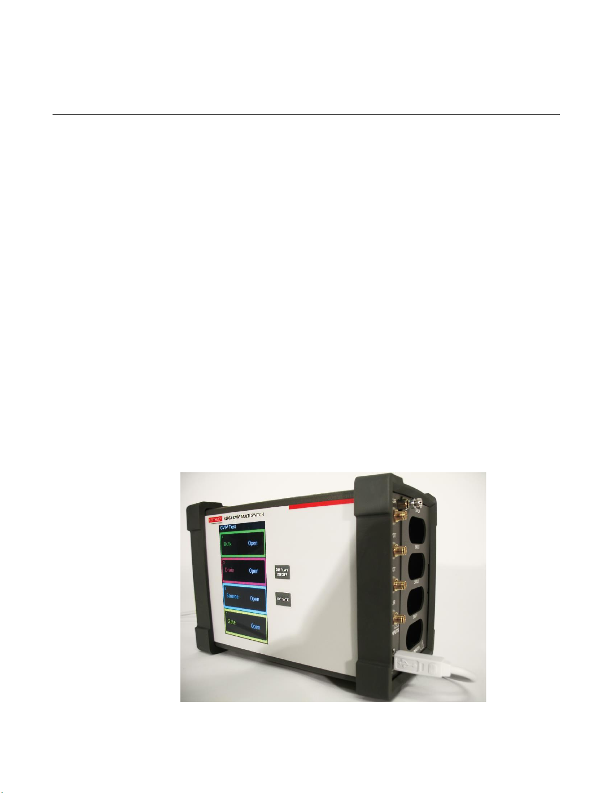
The Keithley Instruments Model 4200A-CVIV Multi-Switch is a multiplexed switching accessory for the
4200A-SCS that allows you to switch between I-V and C-V measurements with no changes to cables
or connections to the device under test (DUT). You can also perform I-V testing with up to four SMUs
(4200-SMU, 4201-SMU, 4210-SMU, or 4211-SMU) and switch the outputs of the 4210-CVU or 4215CVU to any of the four output terminals. This accessory creates a faster and more efficient device
testing workflow for any application that requires I-V and C-V measurements on the same device.
Figure 1: Keithley Instruments Model 4200A-CVIV Multi-Switch
Section 1
Introduction
Page 9
Section 1: Introduction Model 4200A-CVIV Multi-Switch User's Manual
1-2 4200A-CVIV-900-01 Rev. E December 2020
The built-in display provides clear, real-time test information near the DUT. You can personalize the
output naming convention with the Clarius software, rotate to match your testing environment, and
turn off the display to reduce light near the DUT.
Extended warranty
Additional years of warranty coverage are available on many products. These valuable contracts
protect you from unbudgeted service expenses and provide additional years of protection at a fraction
of the price of a repair. Extended warranties are available on new and existing products. Contact your
local Keithley Instruments office, sales partner, or distributor for details.
Contact information
If you have any questions after you review the information in this documentation, please contact your
local Keithley Instruments office, sales partner, or distributor. You can also call the Tektronix
corporate headquarters (toll-free inside the U.S. and Canada only) at 1-800-833-9200. For worldwide
contact numbers, visit tek.com/contact-us.
General ratings
The 4200A-CVIV instrument's general ratings and connections are listed in the following table.
Category
Specification
Voltage rating
210 V
Current rating
1 A
Input and output connections
See DUT connections panel summary (on page 2-2) and Inputs panel
summary (on page 2-3)
Environmental conditions
For indoor use only
Temperature range:
Operating: 10 °C to 40 °C
Storage: −15 °C to 60 °C
Humidity range:
Operating: 5% to 80% relative humidity, noncondensing
Storage: 5% to 90% relative humidity, noncondensing
Altitude:
Operating: 0 to 2000 m (0 to 6252 ft)
Storage: 0 to 4600 m (0 to 15092 ft)
Pollution degree: 1 or 2
Page 10

Model 4200A-CVIV Multi-Switch User's Manual Section 1: Introduction
4200A-CVIV-900-01 Rev. E December 2020 1-3
Specifications
For instrument specifications, search for the 4200A-SCS Parameter Analyzer Datasheet on the
Keithley Instruments website (tek.com/keithley).
Unpack and inspect the instrument
To unpack and inspect the instrument:
1. Inspect the box for damage.
2. Open the top of the box.
3. Remove the accessories and verify that all items are included. You should have received:
▪ Two 4200A-CVIV-SPT SMU Pass-Thru modules
▪ Two channel blockers
▪ Two safety ground cables
▪ One USB cable
▪ One mini ultra-low-noise triaxial cable, 2 m (6.6 ft)
4. Remove the packaging insert.
5. Remove the 4200A-CVIV from the box.
Do not use the front bezel to lift the 4200A-CVIV. Using the front bezel can cause damage to
the instrument.
6. Inspect the instrument for any obvious signs of physical damage.
7. Report any damage to the shipping agent immediately.
Page 11

Section 1: Introduction Model 4200A-CVIV Multi-Switch User's Manual
1-4 4200A-CVIV-900-01 Rev. E December 2020
Hardware and software requirements
The following are required to use the 4200A-CVIV.
• Keithley Instruments 4200A-SCS Parameter Analyzer running the latest software release
• For 2-wire measurements, one 4200-TRX-0.75 or CA-534-24B triaxial cable per channel
• For 4-wire measurements, two 4200-TRX-0.75 or CA-534-24B triaxial cables per channel
• One 4210-CVU or 4215-CVU
• Up to four 4200-SMUs, 4201-SMUs, 4210-SMUs, or 4211-SMUs each, with either 4200-PA
Remote Preamplifiers or 4200A-CVIV-SPT SMU Pass-Thru Modules
For each SMU connected to the 4200A-CVIV, you must also install at least one 4200-PA or
4200A-CVIV-SPT Pass-Thru module.
Page 12

In this section:
Introduction ...............................................................................2-1
DUT connections panel summary .............................................2-2
Inputs panel summary ...............................................................2-3
Display summary ......................................................................2-6
Introduction
This section provides an overview of the 4200A-CVIV display and connectors.
Section 2
Getting started
Page 13

Section 2: Getting started Model 4200A-CVIV Multi-Switch User's Manual
2-2 4200A-CVIV-900-01 Rev. E December 2020
DUT connections panel summary
Device connections are made to the device under test (DUT) instrument panel of the 4200A-CVIV.
The DUT panel of the 4200A-CVIV is shown below. Descriptions of the connections are provided
after the figure.
Figure 2: 4200A-CVIV DUT panel
DUT channel connections
DUT channel
connections
Triaxial force and sense connectors are
provided on channels 1 through 4 for
connection to a DUT.
Page 14

Model 4200A-CVIV Multi-Switch User's Manual Section 2: Getting started
4200A-CVIV-900-01 Rev. E December 2020 2-3
Ground connections
Ground
connections
Two ground screws are provided for connections to protective earth
(safety ground).
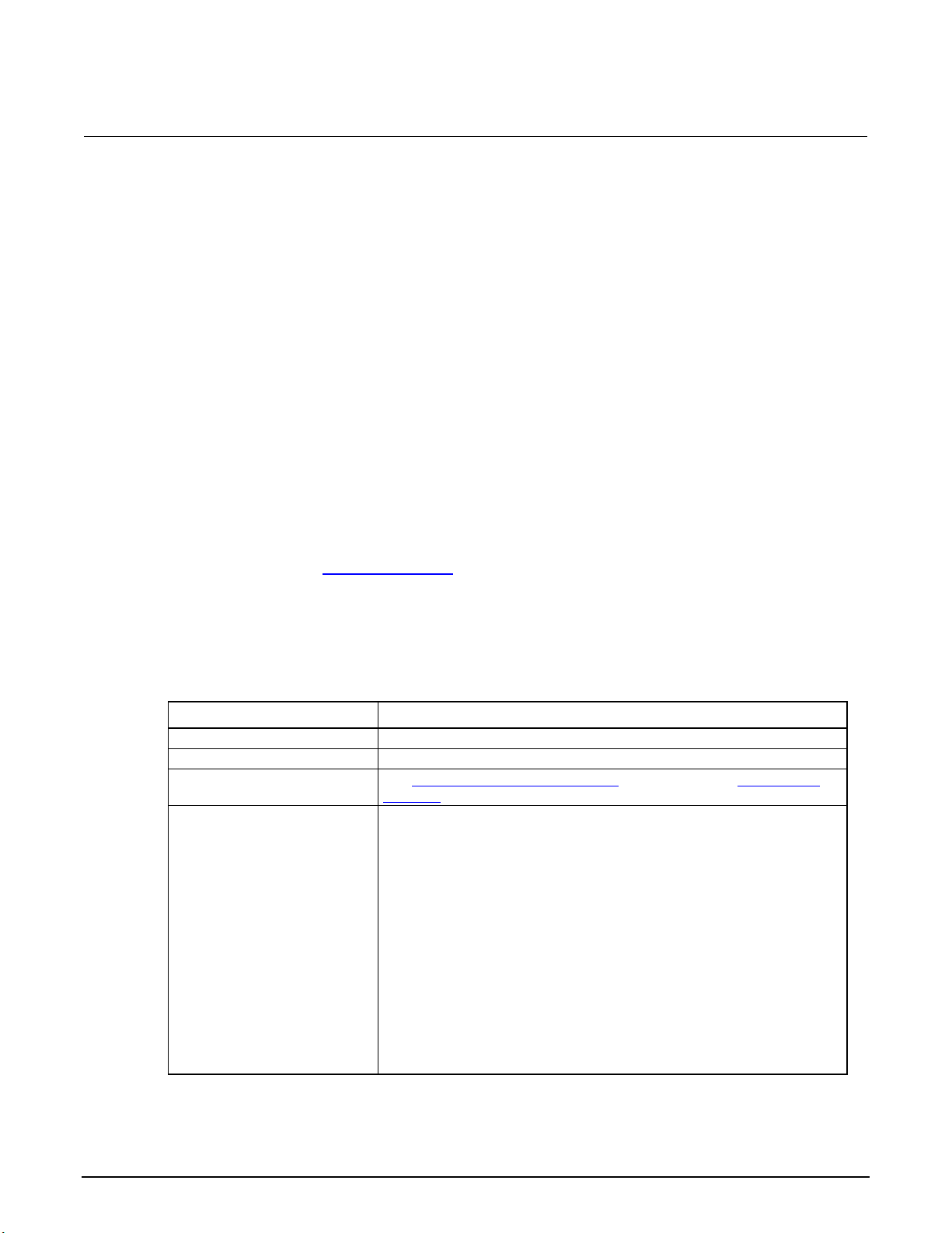
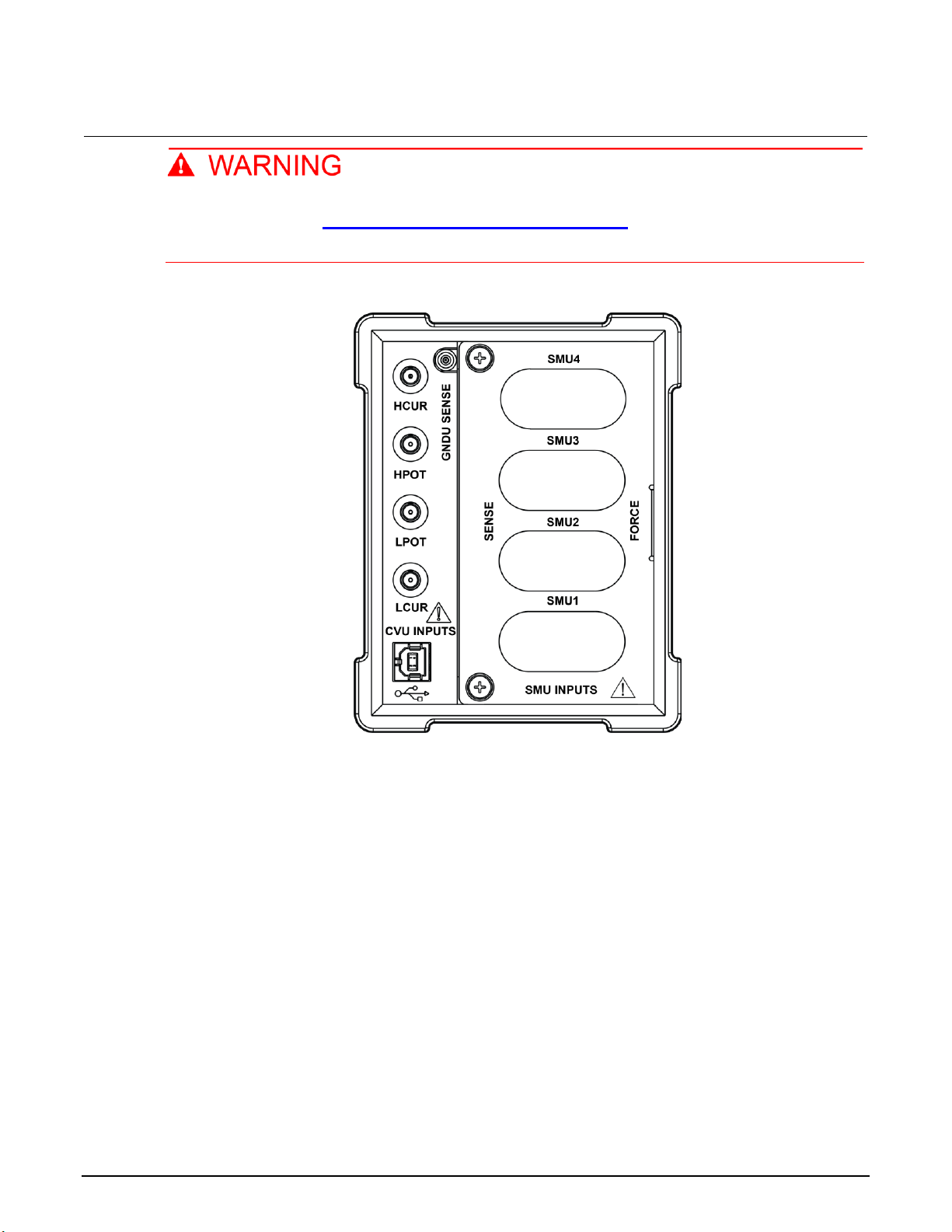
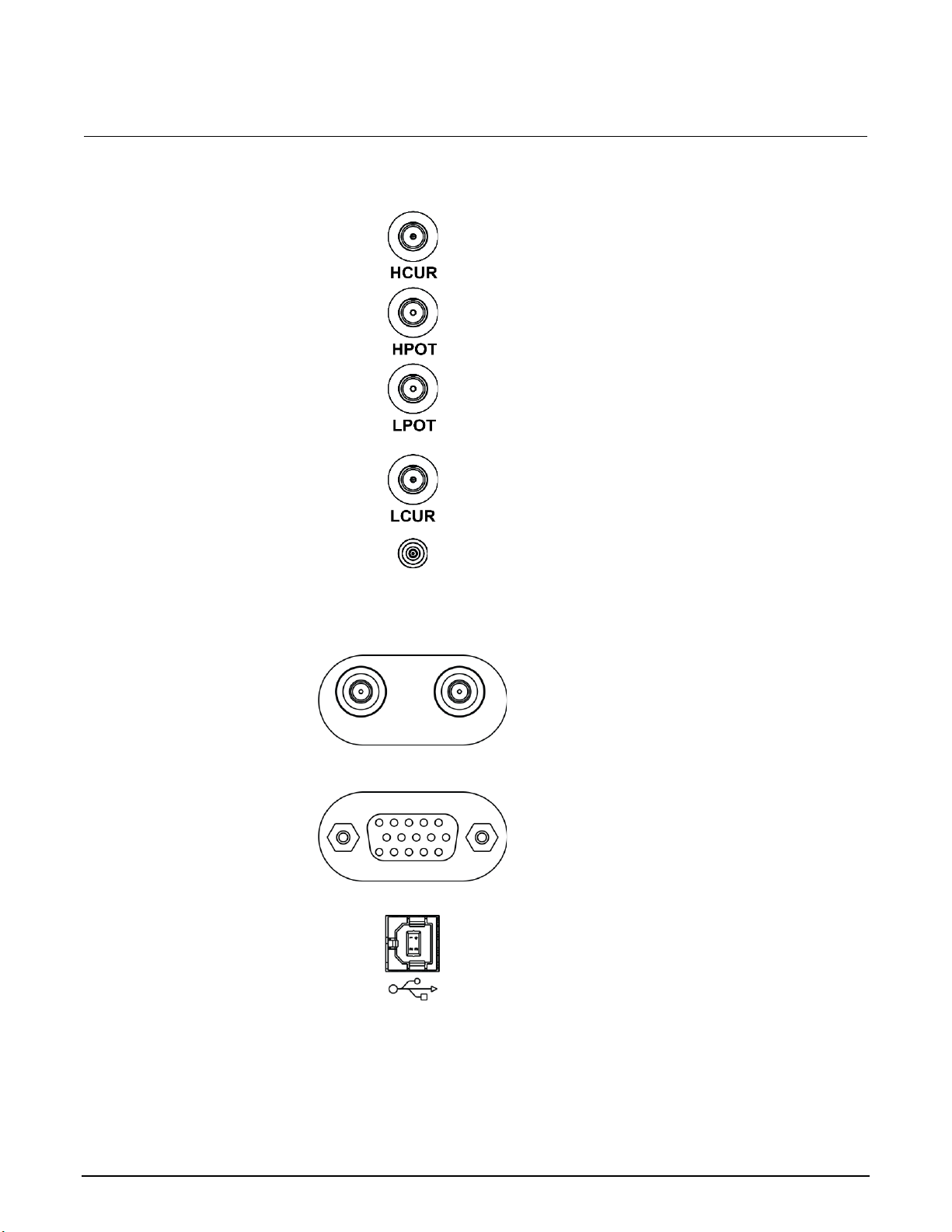
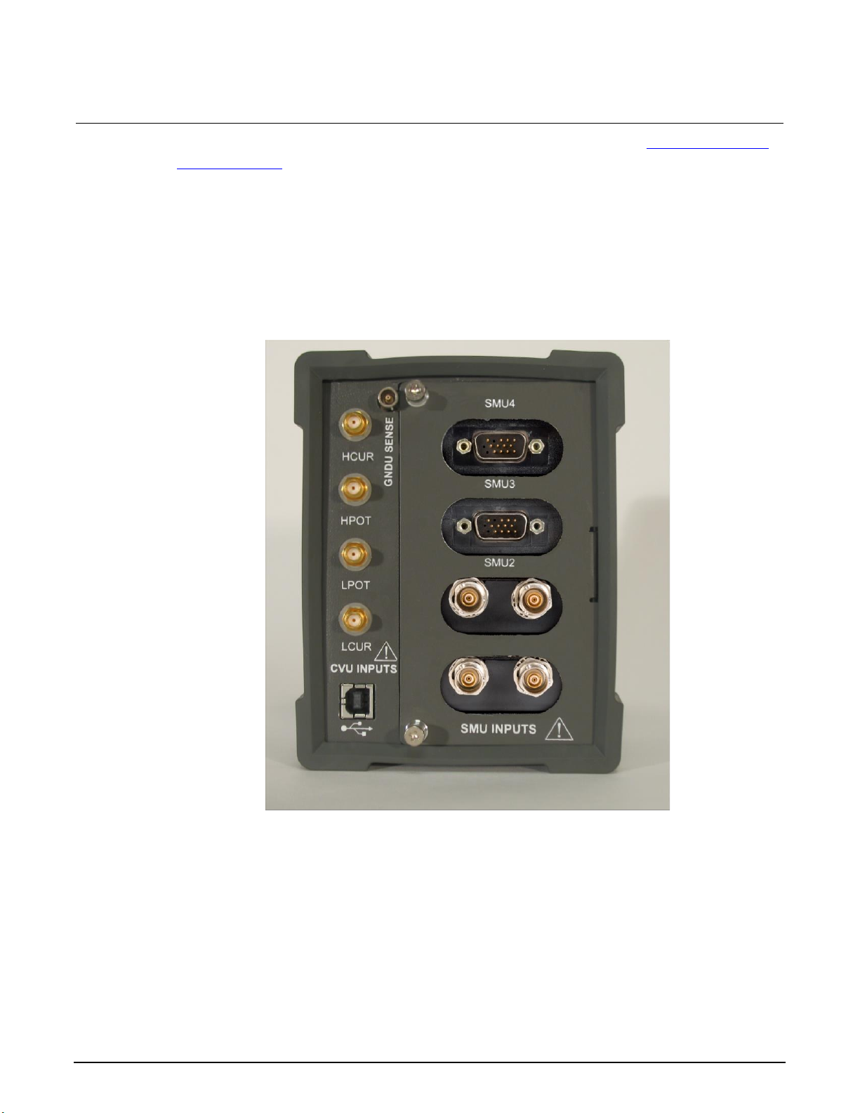
Inputs panel summary
Instruments are connected to the inputs panel of the 4200A-CVIV.
The inputs panel of the 4200A-CVIV is shown below. No preamplifer or pass-through modules are
installed in this figure. Descriptions of the connections are provided after the figure.
GNDU SENSE is available with 4200A-CVIV hardware versions 2.0 or newer.
Page 15
Section 2: Getting started Model 4200A-CVIV Multi-Switch User's Manual
2-4 4200A-CVIV-900-01 Rev. E December 2020
Each SMU input that is not in use must have its access restricted by an included channel
blocker. Refer to the Installing and removing channel blockers (on page 3-7) topic for more
information.
Figure 3: 4200A-CVIV inputs panel (SMU inputs empty)
Page 16
Model 4200A-CVIV Multi-Switch User's Manual Section 2: Getting started
4200A-CVIV-900-01 Rev. E December 2020 2-5
Connections
HCUR CVU input
The HCUR (force HI) CVU input is a female SMA
connector that you use to connect to the
4210-CVU or 4215-CVU.
HPOT CVU input
The HPOT (sense HI) CVU input is a female SMA
connector that you use to connect to the
4210-CVU or 4215-CVU.
LPOT CVU input
The LPOT (sense LO) CVU input is a female SMA
connector that you use to connect to the
4210-CVU or 4215-CVU.
LCUR CVU input
The LCUR (force LO) CVU input is a female SMA
connector that you use to connect to the
4210-CVU or 4215-CVU.
GNDU SENSE
input
The GNDU SENSE input is a female miniature
triaxial connector that you use to connect to the
triaxial SENSE connector of the ground unit on
the 4200A-SCS. This input is only available with
4200A-CVIV hardware versions 2.0 and newer.
SMU inputs
(4200A-CVIV-SPT
SMU Pass-Thru
installed)
The 4200A-CVIV-SPT SMU Pass-Thru module
can be installed in any bay of the 4200A-CVIV.
The triaxial connectors provide a direct interface
with your SMU.
SMU inputs (4200PA Remote
Preamplifier
installed)
The 4200-PA Remote Preamplifier can be
installed in any bay of the 4200A-CVIV. The
preamplifier's serial interface provides a
connection with a 4200-SMU, 4201-SMU, 4210SMU, or 4211-SMU installed in the 4200A-SCS.
USB input
A USB-B port is provided to connect to your
4200A-SCS. The port provides both data and
power to the 4200A-CVIV.
Page 17
Section 2: Getting started Model 4200A-CVIV Multi-Switch User's Manual
2-6 4200A-CVIV-900-01 Rev. E December 2020
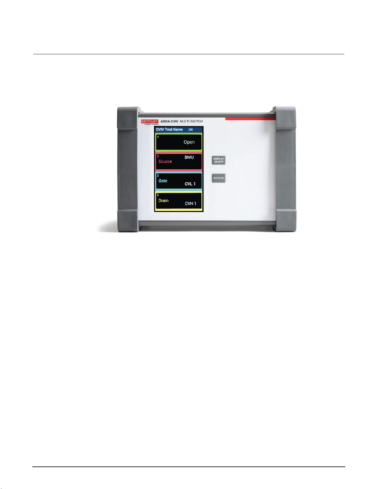
Display summary
Figure 4: 4200A-CVIV front display panel
The 4200A-CVIV features a full-color LCD display that illustrates the name of your test, the name of
the device under test (DUT), the instrument configuration for each channel, and a 2-wire or 4-wire
indicator.
You can turn the display on or off with the DISPLAY ON/OFF button. Press the ROTATE button to
orient the display for your test station configuration.
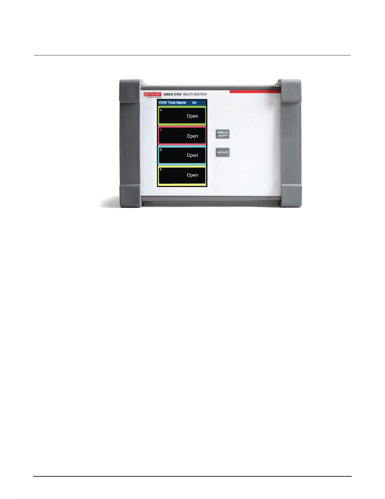
When you reset the 4200A-CVIV, the instrument returns to the default Open state. Any terminal
setting names are removed (see the following figure) and replaced with "Open."
Page 18
Model 4200A-CVIV Multi-Switch User's Manual Section 2: Getting started
4200A-CVIV-900-01 Rev. E December 2020 2-7
Figure 5: Default state display of the 4200A-CVIV
Page 19

In this section:
Introduction ...............................................................................3-1
Mechanical dimensions .............................................................3-1
Location considerations ............................................................3-2
Connect to protective earth .......................................................3-3
Install and remove preamplifier and pass-thru modules ............3-4
Install and remove channel blockers .........................................3-7
Mount the 4200A-CVIV .............................................................3-9
Configure the 4200A-CVIV with KCon ....................................3-10
Introduction
The 4200A-CVIV can be quickly installed and configured for a variety of testing scenarios. This
section contains information on locating and mounting the instrument, safety grounding, using the
instrument with preamplifier modules, and configuration of the instrument using the Keithley
Instruments Configuration Utility (KCon).
Mechanical dimensions
Figure 6: 4200A-CVIV mechanical dimensions, bumpers installed
Section 3
Install and configure the 4200A-CVIV
Page 20
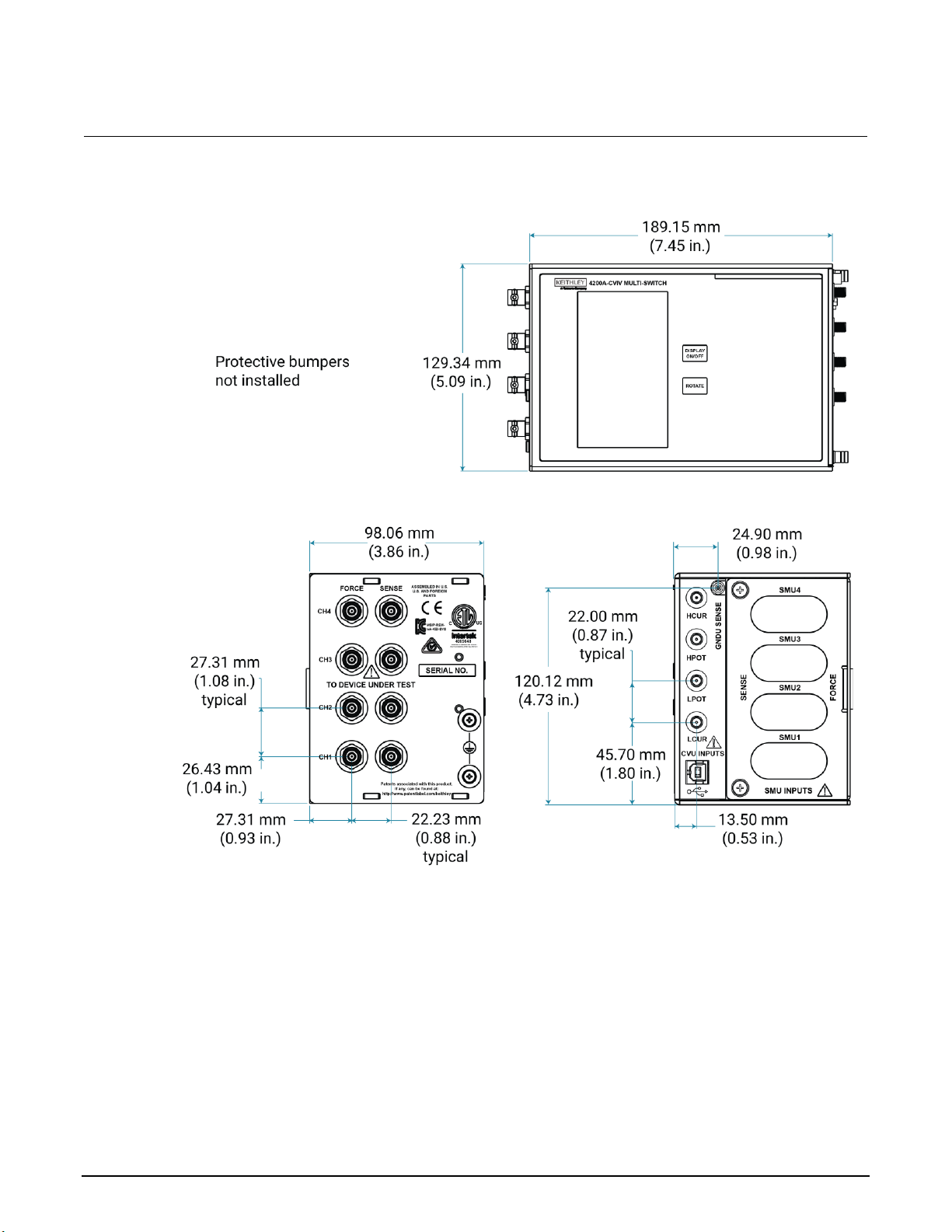
Section 3: Install and configure the 4200A-CVIV Model 4200A-CVIV Multi-Switch User's Manual
3-2 4200A-CVIV-900-01 Rev. E December 2020
Figure 7: 4200A-CVIV mechanical dimensions, bumpers not installed
Location considerations
The 4200A-CVIV is designed to be located as close as possible to a probe station to ensure accurate
measurements.
Page 21
Model 4200A-CVIV Multi-Switch User's Manual Section 3: Install and configure the 4200A-CVIV
4200A-CVIV-900-01 Rev. E December 2020 3-3
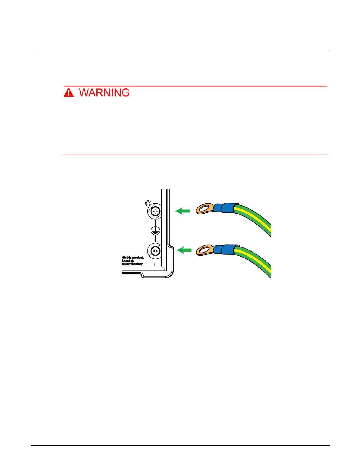
Connect to protective earth
The 4200A-CVIV must be connected to protective earth (safety ground) using both of the
supplied green-yellow ground cables. The ground wires must be attached to both ground
screws on the 4200A-CVIV before powering on the unit, and they must be connected
independently to earth ground (do not connect both ground wires to the same earth safety
ground). Failure to attach the ground wires independently to a known protective earth may
result in personal injury or death due to electric shock.
1. Connect both of the supplied grounding cables to the two grounding terminals of the 4200A-CVIV.
Figure 8: Connecting ground cables to the 4200A-CVIV
2. Connect the ends of the grounding cables to the two independent protective earth (safety ground)
terminals.
Page 22

Section 3: Install and configure the 4200A-CVIV Model 4200A-CVIV Multi-Switch User's Manual
3-4 4200A-CVIV-900-01 Rev. E December 2020
Install and remove preamplifier and pass-thru modules
You can install up to four Keithley Instruments 4200-PA Remote Preamplifiers or 4200A-CVIV-SPT
SMU Pass-Thru modules (see the following figure) in the 4200A-CVIV in any combination.
Figure 9: 4200-PA Remote PreAmp and 4200A-CVIV-SPT SMU Pass-Thru modules
Make sure that the preamplifier and pass-through modules are properly aligned when they are
inserted into the SMU input slots of the 4200A-CVIV. Additionally, be sure to install a channel blocker
in each slot that is not in use (see the WARNING below and the Install and remove channel blockers
(on page 3-7) topic for more information).
Each SMU input on the 4200A-CVIV that is not in use must have its access restricted by an
included channel blocker. Failure to use a channel blocker may result in personal injury or
death due to electric shock.
Page 23
Model 4200A-CVIV Multi-Switch User's Manual Section 3: Install and configure the 4200A-CVIV
4200A-CVIV-900-01 Rev. E December 2020 3-5
To install a preamplifier or pass-through module:
1. Disconnect any cables from the instrument before installing a module.
2. Remove the rubber bumper from the SMU inputs side of the 4200A-CVIV.
3. Using a Phillips-head screwdriver, loosen the two captive screws securing the module door to the
instrument.
4. Completely remove the module door and set it aside.
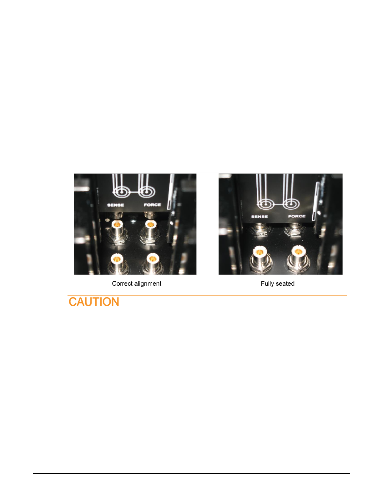
5. Align the module with the alignment rails of a vacant SMU input bay.
6. Firmly insert the module into the instrument until it is seated. Use the following graphics as a
guide.
Figure 10: Correct alignment (left) and fully seated module
Do not use excessive force when installing the preamplifier and pass-thru modules. The
modules are designed to fit securely, but extreme pressure may cause damage to the
modules or the instrument. Always verify the alignment of the module before inserting it into
the 4200A-CVIV.
Page 24
Section 3: Install and configure the 4200A-CVIV Model 4200A-CVIV Multi-Switch User's Manual
3-6 4200A-CVIV-900-01 Rev. E December 2020
7. Place channel blockers into any SMU input slots without a module. See the Install and remove
channel blockers (on page 3-7) topic for installation information.
8. Reinstall the module door.
9. Finger-tighten the captive screws on the module door, or use a screwdriver. Do not overtighten.
Reinstall the protective rubber bumper. A 4200A-CVIV with a pass-thru module installed in SMU slot
4 and a preamplifier in slot 3 is shown in the following graphic. Channel blockers are not installed in
this graphic.
Figure 11: 4200A-CVIV input panel
To remove a preamplifier or pass-through module:
1. Disconnect any cables from the instrument before installing a module.
2. Remove the rubber bumper from the SMU inputs side of the 4200A-CVIV.
3. Loosen the two captive screws securing the module door to the instrument.
4. Completely remove the module door and set it aside.
5. Grasp the module and pull it straight out of the 4200A-CVIV.
Page 25
Model 4200A-CVIV Multi-Switch User's Manual Section 3: Install and configure the 4200A-CVIV
4200A-CVIV-900-01 Rev. E December 2020 3-7
Do not twist the module when removing it from the instrument. Do not use implements to
grasp the triaxial connectors of the pass-through or the serial connector of the preamplifier.
6. Place channel blockers into any SMU input bays without a module. See the Install and remove
channel blockers (on page 3-7) topic for more information.
7. Reinstall the module door.
8. Finger-tighten the captive screws on the module door, or use a Phillips screwdriver. Do not
overtighten.
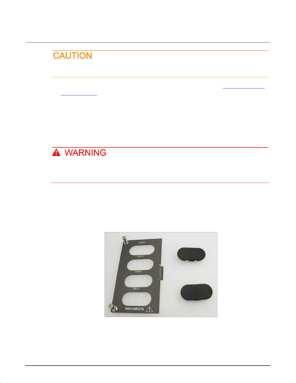
Install and remove channel blockers
Each SMU input on the 4200A-CVIV that is not in use must have its access restricted by an
included channel blocker. Failure to use a channel blocker may result in personal injury or
death due to electric shock.
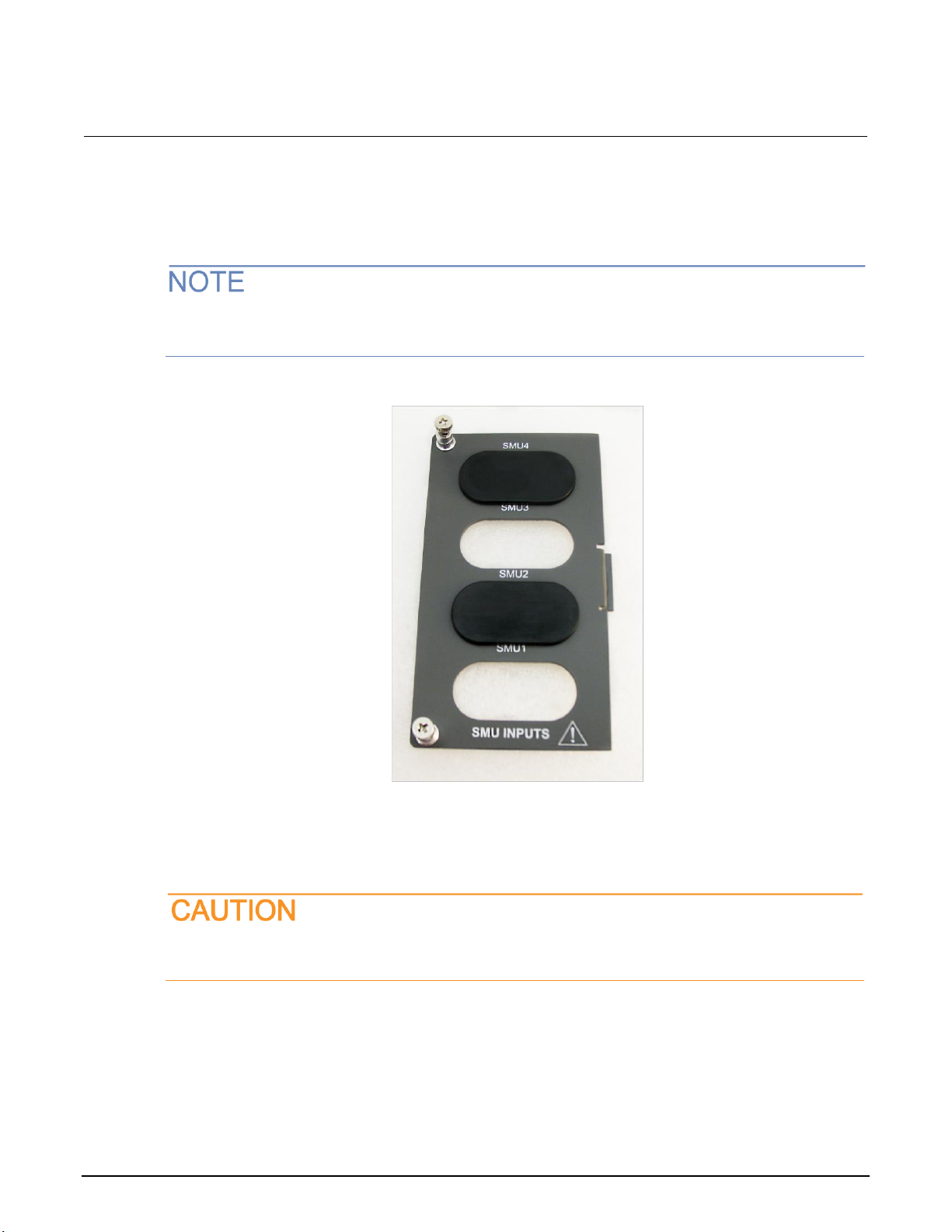
The 4200A-CVIV is shipped with two protective channel blockers. You must install a blocker in each
SMU input module location that is not occupied with a 4200-PA Remote Preamplifier or
4200A-CVIV-SPT SMU Pass-Thru Module. The 4200A-CVIV input panel cover and channel blockers
are shown in the following figure.
Figure 12: 4200A-CVIV input panel cover and channel blockers
Page 26
Section 3: Install and configure the 4200A-CVIV Model 4200A-CVIV Multi-Switch User's Manual
3-8 4200A-CVIV-900-01 Rev. E December 2020
To install a channel blocker:
1. For the vacant channel, place a channel blocker into the opening, smooth side facing out.
2. Press down on the blocker firmly until you hear an audible click. The blocker is now positioned
correctly.
You may need to slightly press one of the tabs on the edge of the blocker flange before it seats flush
with the front of the 4200A-CVIV input panel (see the following figure).
Figure 13: 4200A-CVIV input panel cover with channel blockers installed
To remove a channel blocker:
On the rear of the panel cover, press one of the tabs on the inside edge of the blocker flange while
pushing out. The blocker can now be removed.
To prevent damage to the channel blocker or the input panel, do not use excessive pressure
when removing the channel blocker.
Page 27
Model 4200A-CVIV Multi-Switch User's Manual Section 3: Install and configure the 4200A-CVIV
4200A-CVIV-900-01 Rev. E December 2020 3-9
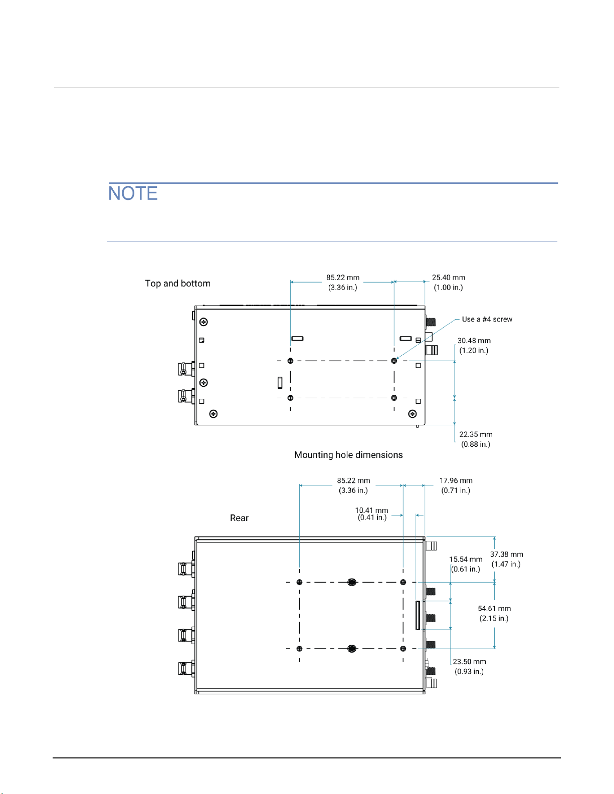
Mount the 4200A-CVIV
The 4200A-CVIV can be mounted to a flat surface with four #4 screws. Threaded mounting holes are
on the top, bottom, and rear panels of the instrument.
Be sure to consider your test station layout, ground cable layout, and other cable routing before
mounting the instrument.
Figure 14: 4200A-CVIV mounting dimensions
Page 28

Section 3: Install and configure the 4200A-CVIV Model 4200A-CVIV Multi-Switch User's Manual
3-10 4200A-CVIV-900-01 Rev. E December 2020
Configure the 4200A-CVIV with KCon
Before using the 4200A-CVIV, you must add the instrument to the 4200A-SCS using the Keithley
Instruments Configuration Utility (KCon). This must be done each time an instrument is added,
changed, or removed from the 4200A-CVIV. The outputs of the 4200A-CVIV are configured within
Clarius+ and are not affected by KCon.
For more information on KCon, see Model 4200A-SCS Setup and Maintenance.
To update the Model 4200A-CVIV configuration:
1. Turn off the 4200A-SCS system power.
2. Connect any SMU to one of the 4200A-CVIV input channel slots.
3. Make connections to the 4210-CVU or 4215-CVU Capacitance-Voltage Unit.
4. Connect the 4200A-CVIV to any USB port on the front or back of the 4200A-SCS using the
included USB Type A to USB Type B cable.
5. Turn on the 4200A-SCS system power.
6. Start the KCon application.
7. Select Update.
8. Select Save.
Page 29

In this section:
Introduction ...............................................................................4-1
4200A-CVIV switching ..............................................................4-2
Measurement compensation ...................................................4-13
Control the Model 4200A-CVIV with Clarius ...........................4-17
Control the 4200A-CVIV with LPT commands ........................4-27
Introduction
This section of the 4200A-CVIV User's Manual covers the following topics:
• 4200A-CVIV switching (on page 4-2)
• Measurement compensation (on page 4-13)
• Control the 4200A-CVIV with the Clarius application (on page 4-17)
• Control the 4200A-CVIV with LPT commands (on page 4-27)
Section 4
Switching and software configuration
Page 30

Section 4: Switching and software configuration Model 4200A-CVIV Multi-Switch User's Manual
4-2 4200A-CVIV-900-01 Rev. E December 2020
4200A-CVIV switching
The 4200A-CVIV has the following output modes:
• Open
• SMU
• CV HI
• CV LO
• CV Guard
• Ground Unit
• AC Coup AC Gnd
• BiasT SMU CV HI
• BiasT SMU CV LO
• BiasT SMU LO I CV HI
• BiasT SMU LO I CV LO
• BiasT SMU AC Gnd
Changing the output mode for each channel reconfigures the switches in the 4200A-CVIV to route the
correct signal to the output terminal. There is also a global 2-Wire/4-Wire CVU setting that affects all
of the channels configured for CV HI and CV LO.
The following table describes each output mode and its typical application.
4200A-CVIV output mode
Application and description
Open (on page 4-4)
Default setting. Also disconnects a channel from the device.
SMU (on page 4-4)
Used for I-V measurements. Connects Force HI and Sense HI to the device.
CV HI (on page 4-5)
Used for C-V measurements. Connects the 4210-CVU or 4215-CVU (HPOT
and HCUR) to the device.
CV LO (on page 4-6)
Used for C-V measurements. Connects the 4210-CVU or 4215-CVU (LPOT
and LCUR) to the device.
CV Guard (on page 4-7)
Used to guard unwanted impedance when making C-V measurements on
multi-terminal devices.
Apply CV Guard to the terminal to be excluded from the C-V measurement.
Ground Unit (on page 4-8)
Used for I-V measurements. Connects Force LO and Sense LO to the device.
Page 31

Model 4200A-CVIV Multi-Switch User's Manual Section 4: Switching and software configuration
4200A-CVIV-900-01 Rev. E December 2020 4-3
4200A-CVIV output mode
Application and description
AC coupled AC ground (on
page 4-9)
Used for C-V measurements. Allows an ac path to ground without providing a
dc path.
BiasT SMU CV HI and
BiasT SMU CV LO (on
page 4-10)
Used for C-V measurements up to 200 V dc bias.
Allows a dc current of up to 1 A, ideal for on-state device measurements.
BiasT SMU LO I CV HI and
BiasT SMU LO I CV LO (on
page 4-11)
Recommended for C-V measurements up to 200 V dc bias.
Allows a dc current of up to 100 µA, ideal for off-state device measurements.
BiasT SMU AC Gnd (on
page 4-11)
Used to guard unwanted impedance when making C-V measurements on
multi-terminal devices. Allows dc bias up to 200 V.
Apply BiasT SMU ac Gnd to the terminal to be excluded from the C-V
measurement.
The following figure shows a simplified diagram of the Model 4200A-CVIV. In this figure, all of the
source-sense pairs are shown as a single wire for simplicity. Each channel has its own set of
switches that control which input channel is routed to the output connectors. Only one option can be
selected for an output at any one time.
The sections following the figure describe the switching options in more detail.
Figure 15: 4200A-CVIV simplified switching
Page 32

Section 4: Switching and software configuration Model 4200A-CVIV Multi-Switch User's Manual
4-4 4200A-CVIV-900-01 Rev. E December 2020
Open
Select the Open setting for an output channel if nothing will be connected to the output terminal. This
is the default setting for the channels upon power up. The switches in the previous figure are all
shown in the open position.
SMU switching
The 4200A-CVIV can connect and disconnect the force and sense terminals of the SMU channels to
the output terminals. For example, select the SMU option for all four channels to perform I-V testing
on a four-terminal device. This setting closes the relays that connect the SMU channels to the output
connectors. The following figure shows a simplified diagram of the SMU switching configuration.
Figure 16: 4200A-CVIV SMU switching configuration
The 4200A-CVIV instrument is not a full SMU switching matrix and it is not possible to connect an
input SMU channel to a different output channel.
Page 33

Model 4200A-CVIV Multi-Switch User's Manual Section 4: Switching and software configuration
4200A-CVIV-900-01 Rev. E December 2020 4-5
CV HI switching
The 4200A-CVIV can switch the HI connections of the 4210-CVU or 4215-CVU (HPOT and HCUR) to
any of the output channels. You can make C-V measurements between any set of output terminals.
The CV HI setting can also be applied to more than one output terminal at a time if you are
connecting multiple device terminals during C-V measurements. The following figure shows a
simplified diagram of the CV HI switching configuration.
Figure 17: 4200A-CVIV CV HI switching configuration
Page 34

Section 4: Switching and software configuration Model 4200A-CVIV Multi-Switch User's Manual
4-6 4200A-CVIV-900-01 Rev. E December 2020
CV LO switching
The 4200A-CVIV can switch the LO connections of the 4210-CVU or 4215-CVU (LPOT and LCUR) to
any of the output channels. You can perform C-V measurements between any set of output terminals.
The CV LO setting can also be applied to more than one output terminal if you are connecting
multiple device terminals during C-V measurements. The following figure shows a simplified diagram
of the CV LO switching configuration.
Figure 18: 4200A-CVIV CV LO switching configuration
Page 35

Model 4200A-CVIV Multi-Switch User's Manual Section 4: Switching and software configuration
4200A-CVIV-900-01 Rev. E December 2020 4-7
CV Guard switching
The 4200A-CVIV can apply an effective guard signal to any output terminal. You can make C-V
measurements while guarding device terminals that should not be included in the measurement. The
CV GRD setting can also be applied to more than one output terminal at a time if you are guarding
multiple device terminals during C-V measurements.
The following figure shows a simplified diagram of the CV GRD switching configuration. This mode
provides an ac low impedance ground return through the 4200A-CVIV to be used for guarding out
terminals used in CV measurements.
Figure 19: 4200A-CVIV CV GRD switching configuration
The CV GRD mode cannot be used as a dc ground for SMUs in a test configuration. Model
4200A-SCS ground unit multiplexing is available for the 4200A-CVIV with hardware version 2.0 or
later. See Ground unit switching (on page 4-8) for more information.
Page 36

Section 4: Switching and software configuration Model 4200A-CVIV Multi-Switch User's Manual
4-8 4200A-CVIV-900-01 Rev. E December 2020
Ground unit switching
The 4200A-CVIV supports a ground unit (GNDU) that can be switched to any one of the four output
channels. You can use a miniature triaxial-to-triaxial cable assembly to connect GNDU SENSE on the
4200A-CVIV to the SENSE connector of the ground unit on the 4200A-SCS. You do not need to
make a physical connection between the FORCE connection of the Model 4200A-SCS ground unit
and the Model 4200A-CVIV, as the connection is made through the outer shield of the triaxial cable.
Keithley Instruments does not recommend configuring multiple GNDU channels when GNDU SENSE
is connected. Different terminals can have different potentials, which may cause measurement errors.
The GNDU detects whether the test configuration is 2-wire or 4-wire.
The ground unit switching mode is only available with 4200A-CVIV hardware versions 2.0 or newer.
Figure 20: 4200A-CVIV GNDU switching configuration connection
Page 37

Model 4200A-CVIV Multi-Switch User's Manual Section 4: Switching and software configuration
4200A-CVIV-900-01 Rev. E December 2020 4-9
AC coupled AC ground configuration
The following figure shows a 4200A-CVIV ac coupled with ac ground configuration. This mode
provides an ac-coupled, low-impedance return to ground through the 4200A-CVIV, and also blocks
the dc component of the signal. This configuration allows the dc signal to float, and the ac signal is
grounded.
A typical application for this configuration would be when performing a C-V measurement on a
three-terminal device. Two of the terminals would be designated as CV HI and CV LO, and the third
terminal would be grounded through a capacitor. The dc bias is provided by the DUT, while the ac
signal is grounded.
Figure 21: 4200A-CVIV ac-coupled ac ground configuration
Bias tee switching
The 4200A-CVIV supports a bias tee on each of its four channels to allow dc biasing of ac signals at
the channel outputs. The bias tee modes use the CVU to measure the capacitance and the SMUs to
sweep the voltage or apply a dc bias of up to ± 200 V, or 400 V differential. The bias tees also enable
a current compliance of up to 100 mA or 1 A, depending on the SMU.
Bias tee configuration modes are for C-V measurements only. For I-V measurements, use the SMU
configuration mode.
Page 38

Section 4: Switching and software configuration Model 4200A-CVIV Multi-Switch User's Manual
4-10 4200A-CVIV-900-01 Rev. E December 2020
You can select bias tee modes in Clarius+, as shown in the following figure. The CvsT and SweepV
tests in the hivcvulib user library can be used with the bias tee modes.
Figure 22: Bias tee mode selection
BiasT SMU CV HI and BiasT SMU CV LO
The following figure shows a 4200A-CVIV bias tee high-current SMU configuration with a CV HI or LO
switching configuration. This combines the dc bias from a 4200-SMU, 4201-SMU, 4210-SMU, or
4211-SMU with an ac signal from CV HI or LO through a 4200A-CVIV bias tee circuit. This mode is
ideal for performing C-V measurements where a dc bias current of up to 1 A is required, such as
when making C-V measurements on a semiconductor in the on-state.
Figure 23: 4200A-CVIV bias tee, high current SMU CV HI or LO switching configuration
Page 39

Model 4200A-CVIV Multi-Switch User's Manual Section 4: Switching and software configuration
4200A-CVIV-900-01 Rev. E December 2020 4-11
BiasT SMU LO I CVI HI and BiasT SMU LO I CV LO
The following figure shows a 4200A-CVIV bias tee low-current SMU configuration with a CV HI or LO
switching configuration. This combines the dc bias from a 4200-SMU, 4201-SMU, 4210-SMU, or
4211-SMU with an ac signal from CV HI or LO through the 4200A-CVIV bias tee circuit. This mode is
optimized for use with currents below 100 µA. It is the preferred mode for semiconductors in the offstate.
Figure 24: 4200A-CVIV bias tee, low current SMU CV HI or LO switching configuration
Bias tee SMU AC ground
The following figure shows a 4200A-CVIV bias tee with an ac ground configuration. This combines
the dc bias from a 4200-SMU, 4201-SMU, 4210-SMU, or 4211-SMU with local ac ground through the
4200A-CVIV bias tee circuit.
A typical application for this configuration would be when performing a C-V measurement on the drain
to the source of a MOSFET while applying a dc bias to the gate. The ac signals at the gate would
have a ground return path.
Figure 25: 4200A-CVIV bias tee AC ground configuration
Page 40

Section 4: Switching and software configuration Model 4200A-CVIV Multi-Switch User's Manual
4-12 4200A-CVIV-900-01 Rev. E December 2020
Automate switching between 2-wire and 4-wire mode
C-V measurements are typically performed in 4-wire mode with each source and sense pair
(HCUR/HPOT pair and LCUR/LPOT pair) terminated together as close to the device under test (DUT)
as possible. However, this setup can become difficult in switching applications where I-V and C-V
measurements are made using the same cabling. The 4200A-CVIV can make 4-wire measurements,
but it can also switch to 2-wire measurements when only two cables are connected to the DUT.
In 2-wire C-V mode, the source and sense pairs are terminated together internally and the coupled
signal is passed to the selected output terminal on the source signal line. This setup is useful when
you want to run the fewest number of triaxial cables to the DUT or if you are only making 2-wire I-V
measurements and do not want to run extra triaxial cables for the C-V measurements. The following
figure shows the CV HI and CV LO circuits in 2-wire mode. The output channel switches are omitted
in the figure.
Figure 26: 4200A-CVIV CV HI and CV LO channels configured in 2-wire sense mode
Page 41

Model 4200A-CVIV Multi-Switch User's Manual Section 4: Switching and software configuration
4200A-CVIV-900-01 Rev. E December 2020 4-13
In 4-wire C-V mode, the source and sense pairs are independent of each other as they pass through
the 4200A-CVIV. The HCUR and LCUR signals are routed directly to the source output terminal of
the specified output channel and the HPOT and LPOT signals are routed directly to the sense output
terminal of the specified output channel. This setup is useful if you already have 4-wire Kelvin
connections to the DUT for I-V testing. The following figure shows the CV HI and CV LO circuits in
4-wire mode. The output channel switches are omitted in the figure.
Figure 27: 4200A-CVIV CVHI and CVLO channels configured in the 4-wire sense mode
It is best to use 4-wire mode for measuring low impedance in both I-V and C-V applications. Four-wire
mode removes the effect of the cable impedance by sensing voltage directly at the device terminals.
The effect of cable impedance is more pronounced with low impedance devices because parasitic
impedance in the cabling can become larger than that of the device itself.
Measurement compensation
Using the 4200A-CVIV with a 4210-CVU or 4215-CVU causes some degradation in CVU
measurement accuracy. To resolve this, perform compensation with the 4200A-CVIV.
You run the cvu-comp-cviv-collect action in Clarius to gather open, short, and load
compensation values that you apply to CVU readings.
Page 42

Section 4: Switching and software configuration Model 4200A-CVIV Multi-Switch User's Manual
4-14 4200A-CVIV-900-01 Rev. E December 2020
CVU compensation
Offset and gain errors caused by the connections between the 4210-CVU or 4215-CVU, 4200A-CVIV,
and the device under test (DUT) can be corrected by using connection compensation. General CVU
compensation is a two-part process:
1. Generate connection compensation values for open, short, and load conditions. The
compensation values are stored for future use.
2. Enable the compensation values for open, short, or load before running the interactive test
module (ITM).
When using the 4200A-CVIV, perform compensation for each switch configuration used for C-V
measurements in the test application. For example, perform compensation three times (one time for
each C-V setup) if you plan to switch between three different C-V measurement setups on the
terminals of a 3-terminal device.
The compensation values for all 4200A-CVIV configurations are stored by the Clarius+ software.
When you run a test, the enabled compensation values are factored into each measurement. If you
do not perform compensation for the current 4200A-CVIV configuration, the software will use the
default compensation constants, which are equivalent to no compensation. If you disable open, short,
and load compensation in a test, the software does not apply the compensation values to the test
results.
Perform connection compensation any time the connection setup is changed or disturbed. Changes
in temperature or humidity do not affect connection compensation.
Guidelines to determine required compensation
Use the following general guidelines to determine which compensation needs to be done:
• Open compensation: Offset compensation for small capacitance (> 1 MΩ, large impedance)
• Short compensation: Offset compensation for large capacitance (< 10 Ω, small impedance)
• Load compensation: Resistive load compensation for gain error (seldom used)
Once you complete compensation for a specific 4200A-CVIV configuration, it is not necessary to
gather compensation values each time you switch back to that configuration. However, over time the
compensation values required for each configuration can drift from their original value. To avoid this,
gather compensation values periodically for each switching configuration to make sure that the
system is using the most accurate compensation values.
Page 43

Model 4200A-CVIV Multi-Switch User's Manual Section 4: Switching and software configuration
4200A-CVIV-900-01 Rev. E December 2020 4-15
Model 4200A-CVIV compensation connections
Connect the output cables for open, short, or load compensation. Repeat this process for each
channel configuration being compensated. The following figure examples are shown using channels 1
and 2, but the same connection scheme applies for any channel configuration. The following figure
shows the connections for 2-wire and 4-wire open compensation. In 2-wire mode, leave the ends of
the triaxial cables disconnected. In 4-wire mode, connect the force and sense triaxial cables for each
channel with a triaxial tee connector.
For all compensation connections, make sure that the outer shields of the triaxial cables are shorted
together as close to the DUT as possible for optimal measurements. This is commonly done by
attaching the triaxial connectors to a test fixture.
See the Model 4200A-SCS Reference Manual for additional compensation information
The DUT side of the 4200A-CVIV is intended to be used only with the 4200-TRX-0.75 or
CA-534-24A blue triaxial cables. Four-wire connection compensation is not supported with other
cables.
Figure 28: Connections for open connection compensation
Page 44

Section 4: Switching and software configuration Model 4200A-CVIV Multi-Switch User's Manual
4-16 4200A-CVIV-900-01 Rev. E December 2020
The following figure shows the connections for 2-wire and 4-wire short compensation. In 2-wire mode,
short the force leads at the test fixture or at a probe station. In 4-wire mode, connect the force and
sense triaxial cables for each channel with a triaxial tee connector. Short the outputs at the test fixture
or at a probe station.
Figure 29: Connections for short connection compensation
Page 45

Model 4200A-CVIV Multi-Switch User's Manual Section 4: Switching and software configuration
4200A-CVIV-900-01 Rev. E December 2020 4-17
The following figure shows the connections for 2-wire and 4-wire load compensation. In 2-wire mode,
connect the ends of the triaxial cables to the load. The load can be in a test fixture or a probe station.
In 4-wire mode, connect the force and sense triaxial cables for each channel with a triaxial tee
connector. Connect the triaxial tee outputs to the load.
Figure 30: Connections for load connection compensation
Control the Model 4200A-CVIV with Clarius
The Keithley Instruments Clarius+ software is preinstalled on your 4200A-SCS Parameter Analyzer.
You can use Clarius+ to control the outputs of your 4200A-CVIV and its onboard display.
There are two actions built into the Clarius+ software on the 4200A-SCS that are used to control the
4200A-CVIV: cviv-configure and cvu-cviv-comp-collect. Each of these actions is also
available as a user module in the cvivulib user library.
For more information on Clarius+, see the Model 4200A-SCS Parameter Analyzer Reference Manual.
Page 46

Section 4: Switching and software configuration Model 4200A-CVIV Multi-Switch User's Manual
4-18 4200A-CVIV-900-01 Rev. E December 2020
cviv-configure
The cviv-configure action is used to set up and control the 4200A-CVIV output channels when
performing a C-V or I-V test. To use the action, add it to the project tree structure and execute it when
you want to reconfigure channels. The cviv-configure action can control the channel
configuration, 2-wire and 4-wire CVU sense settings, and the names of the test and channels shown
on the 4200A-CVIV display. The parameters for the action are shown in the table following the
graphic.
Figure 31: Clarius+ cviv-configure action
Page 47

Model 4200A-CVIV Multi-Switch User's Manual Section 4: Switching and software configuration
4200A-CVIV-900-01 Rev. E December 2020 4-19
Adjustable parameters in the cviv-configure module
Detailed descriptions of the input parameters are as follows:
Ch1-4Mode: The instrument terminal that is connected to an output channel specified by numbers 1
through 4. The options are:
• Open: No Connection. The output channel is an open circuit.
• SMU: The output channel signals pass through the SMU terminals.
• CV HI: The output channel is connected to the CVU HI side terminals.
• CV LO: The output channel is connected to the CVU LO side terminals.
• CV Guard: The output channel is connected to the guard (outside shield) of the CVU cables.
• GNDU: The output channel is connected to the SENSE connector of the ground unit on the
4200A-SCS.
• AC Coup AC Gnd: The output channel is connected to ac-coupled ac ground.
• BiasT: SMU CV HI: The output channel is connected to the SMU and the CVU HI side terminals.
• BiasT: SMU CV LO: The output channel is connected to the SMU and the CVU LO side
terminals.
• BiasT: SMU LO I CV HI: The output channel is connected to the SMU and the CVU HI side
terminals. This parameter is optimized for lower SMU current (I).
• BiasT: SMU LO I CV LO: The output channel is connected to the SMU and the CVU LO side
terminals. This parameter is optimized for lower SMU current (I) .
• BiasT: SMU AC Gnd: The output channel is connected directly to ground and the SMU through
the bias tee.
CH1-4TermName: Up to six characters of text that appear on the 4200A-CVIV display next to the
output channel specified by numbers 1 through 4.
TestName: Up to sixteen characters of text that appear at the top of the 4200A-CVIV display. This
allows you to enter a name for the test.
TwoWireMode: Selects whether the 4210-CVU or 4215-CVU outputs in two-wire or four-wire mode.
This affects all output channels configured to CV HI or CV LO. Output channels configured to SMU or
CV Guard are not affected.
• Two Wire: The sense output terminal is not used. The CUR and POT lines of CV HI or CV LO
are shorted internally and connected to the force terminal of any output channel(s) specified by
Ch1-4Mode.
• Four Wire: The POT and CUR lines of CV HI and CV LO are not shorted internally. POT is
connected to sense while CUR is connected to force for any output channel specified by
Ch1-4Mode.
Page 48

Section 4: Switching and software configuration Model 4200A-CVIV Multi-Switch User's Manual
4-20 4200A-CVIV-900-01 Rev. E December 2020
cviv-configure return values
Two values are returned from cviv-configure to the Analyze sheet. The cviv_configure value
returns a status number to indicate how the test completed. The ConstantsName value returns the
configuration settings in the form of a short string of text used when CVU compensation is performed.
Figure 32: Analyze view of the completed cviv-configure action
Detailed descriptions of the return parameters are as follows:
cviv_configure: A value that indicates if the action completed with any errors. The following
values are the possible parameters.
▪ 0 : Pass (no errors)
▪ -1 : Invalid CVIV instrument Id
▪ -2 : Display configuration error
▪ -78 : Received Timeout Waiting for CVIV Response
▪ -88 : Bad Configuration of Data Sent to CVIV
▪ -122 : Invalid parameter
▪ -150 : CVIV Device Not Found
▪ -167 : Invalid CVIV Connection Configuration
▪ -169 : CVIV Unit Name not configured
If you receive -1, -150, or -169, run the KCon application and select Validate.
Page 49

Model 4200A-CVIV Multi-Switch User's Manual Section 4: Switching and software configuration
4200A-CVIV-900-01 Rev. E December 2020 4-21
ConstantsName: The name of the file contains the 4200A-CVIV configuration set in the user
module. Any CVU tests run after the cviv-configure action use this file and its contents.
The format of the string is:
constants_<2W/4W>_<Ch1_Mode>_<Ch2 Mode>_<Ch3 Mode>_<Ch4 Mode>_<cable
length>
The possible values are:
• <2W/4W> : 0 = 4-wire, 1 = 2-wire
• <Ch_Mode> : 0 = open, 1 = SMU, 2 = CV HI, 3 = CV LO, 4 = CV Guard 5 = Ground Unit, 6 =
AC Coup AC Gnd, 7 = BiasT: SMU CV HI, 8 = BiasT: SMU CV LO, 9 = BiasT: SMU LO I CV
HI, 10 = BiasT: SMU LO I CV LO, 11 = BiasT: SMU AC Gnd
• <cable length>:
▪ 4 = 1.5 m CVIV 2-wire
▪ 5 = 1.5 m CVIV 4-wire 0.75 m (for use with the 4200-TRX-0.75 triaxial cables)
▪ 6 = 1.5 m CVIV 4-wire 0.61 m (for use with CA-534-24B blue triaxial cables)
For example, constants_1_2_3_0_0_4 signifies 2-wire mode, CV HI connected to channel 1, CV
LO connected to channel 2, open connections for channels 3 and 4, and a cable length of 1.5 m CVIV
2-wire.
Page 50

Section 4: Switching and software configuration Model 4200A-CVIV Multi-Switch User's Manual
4-22 4200A-CVIV-900-01 Rev. E December 2020
cvu-cviv-comp-collect
The cvu-cviv-comp-collect action is used to perform open, short, and load compensations on
the 4200A-CVIV channels before running a C-V test. The action configures the 4200A-CVIV channels
before performing compensation, so it is not necessary to use the cviv-configure action before
compensation. To use this action, it must be added into the project tree structure and executed once
for each C-V measurement configuration used in the project.
The parameters in cvu-cviv-comp-collect are used to define the connections to the
4200A-CVIV output channels that will be used in your test. You must run the action for each
4200A-CVIV configuration that will be used, as compensation values are unique for each
configuration. Details on each parameter are listed in this topic.
If more than one type of compensation is selected, open compensation is done first, then short, then
load. Dialog boxes prompt you to make the proper connections as described in Compensations (on
page 4-13). To learn more about compensation and the connections required for each type, see the
Compensations (on page 4-13) topic. For a specific example of how to set up a project that includes
CVIV compensation switching in Clarius+, see Use the 4200A-CVIV Multi-Switch (on page 6-1).
Figure 33: Clarius+ cvu-cviv-comp-collect action
Page 51

Model 4200A-CVIV Multi-Switch User's Manual Section 4: Switching and software configuration
4200A-CVIV-900-01 Rev. E December 2020 4-23
Input parameters in the cvu-cviv-comp-collect action
Checkbox
Range
Description
CableLength
▪ 1.5 m CVIV 2 wire
▪ 1.5 m CVIV 4 wire, 0.75 m
▪ 1.5 m CVIV 4 wire, 0.61 m,
blue
Length of the cables from the output channels of the
DUT to the Model 4200A-CVIV.
The 1.5 m CVIV 4 wire, 0.75 m parameter is
intended for use with 4200-TRX-0.75 triaxial cables.
The 1.5 m CVIV 4 wire, 0.61 m parameter is
intended for use with CA-534-24B blue triaxial
cables.
Select_Open
Selected or cleared
Selects whether to perform open compensation.
Select_Short
Selected or cleared
Selects whether to perform short compensation.
Select_Load
Selected or cleared
Selects whether to perform load compensation.
LoadValue
0 to 10e3
The value of the resistance standard (in Ω) to be
used in load compensation.
Ch1-4_Mode
Open, SMU, CV HI, CV LO, CV
Guard, Ground Unit, AC Coup AC
Gnd, BiasT: SMU CV HI, BiasT:
SMU CV LO, BiasT: SMU CV LO,
BiasT: SMU LO I CV HI, BiasT:
SMU LO I CV LO, BiasT: SMU AC
Gnd
The instrument terminal that will be connected to the
corresponding output channel.
CV_2W_Mode
Two Wire, Four Wire
Selects whether the CVU terminals are shorted
internally (Two Wire) or not (Four Wire).
Ch1-4_TermName
Up to 6 alphanumeric characters
Text that appears on the 4200A-CVIV display
labeling the corresponding output channel.
TestName
Up to 16 alphanumeric characters
Text that appears at the top of the 4200A-CVIV
display.
Detailed descriptions of the input parameters are as follows:
CableLength: For the most accurate results, the cables from the output channels of the 4200A-CVIV
must all be the same length. The recommended length is 75 cm, though other lengths can be used.
Select_Open: Select this box to have open compensation be performed when the action is executed.
Select_Short: Select this box to have short compensation be performed when the action is executed.
Select_Load: Select this box to have load compensation be performed when the action is executed.
LoadValue: The value of the resistance standard (in Ω) used in the load compensation. Preferred
values range from 0 to 200 Ω, but any value up to 10 kΩ may be used. This value is not used if
Select_Load is cleared.
Ch1-4_Mode: The instruments to be connected to each respective output channel. These must be
the same connections that will be used in the cviv-configure action when you execute your test.
CV_2W_Mode: Determines if the 4210-CVU or 4215-CVU is in 2-wire or 4-wire mode. This is the
same setting that will be used in the cviv-configure action when you execute your test.
Ch1-4_TermName: Text that appears on the 4200A-CVIV display when the action is running,
labeling the corresponding output channel. The text here does not affect compensation.
Page 52

Section 4: Switching and software configuration Model 4200A-CVIV Multi-Switch User's Manual
4-24 4200A-CVIV-900-01 Rev. E December 2020
TestName: Text that appears at the top of the 4200A-CVIV display while the action is running. The
text here does not affect compensation.
cvu-cviv-comp-collect return values
Two values are returned from cvu-cviv-comp-collect to the Analyze sheet. The
cvu_cviv_comp_collect value returns a status number to indicate how the test completed. The
ConstantsName value returns a string that contains the coded configuration settings.
Figure 34: Analyze view of the completed cvu-cviv-comp-collect action
Detailed descriptions of the return parameters are as follows:
cvu-cviv-comp-collect: A value that indicates if the action completed with any errors.
Possible values and associated explanations are:
▪ 0 : Pass (no errors)
▪ -1 : Invalid CVU instrument identification
▪ -2 : Invalid CVIV instrument identification
▪ -3 : Error: No CV HI connection configured
▪ -4 : Error: No CV LO connection configured
▪ -5 : Display configuration error
▪ -6 : Load Value out of range (0 to 10 K)
▪ -78 : Receive timeout waiting for CVIV response
▪ -88 : Bad configuration of data sent to CVIV instrument
▪ -122 : Invalid parameter
▪ -150 : CVIV device not found
▪ -167 : Invalid CVIV connection configuration
▪ -169 : CVIV instrument name not configured
Page 53

Model 4200A-CVIV Multi-Switch User's Manual Section 4: Switching and software configuration
4200A-CVIV-900-01 Rev. E December 2020 4-25
If you receive the -2, -150, or -169 return values, run the KCon application and select Validate.
ConstantsName: This is the CVU compensation file containing open, short, and load correction
values. The name of the file contains the Model 4200A-CVIV configuration set in the user module.
Any CVU tests run after the cvu-cviv-comp-collect action use this file and its contents.
The format of the string is:
constants_<2W/4W>_<Ch1_Mode>_<Ch2 Mode>_<Ch3 Mode>_<Ch4 Mode>_<cable
length>
The possible values are:
• <2W/4W> : 0 = 4-wire, 1 = 2-wire
• <Ch_Mode> : 0 = open, 1 = SMU, 2 = CV HI, 3 = CV LO, 4 = CV Guard 5 = Ground Unit, 6 =
AC Coup AC Gnd, 7 = BiasT: SMU CV HI, 8 = BiasT: SMU CV LO, 9 = BiasT: SMU LO I CV
HI, 10 = BiasT: SMU LO I CV LO, 11 = BiasT: SMU AC Gnd
• <cable length>:
▪ 4 = 1.5 m CVIV 2-wire
▪ 5 = 1.5 m CVIV 4-wire 0.75 m (for use with the 4200-TRX-0.75 triaxial cables)
▪ 6 = 1.5 m CVIV 4-wire 0.61 m (for use with CA-534-24B blue triaxial cables)
For example, constants_1_2_3_0_0_4 signifies 2-wire mode, CV HI connected to channel 1, CV
LO connected to channel 2, open connections for channels 3 and 4, and a cable length of 1.5 m CVIV
2-wire.
Enable compensation for a test
After you use the cvu-cviv-comp-collect action to gather compensation values for the channels
of the 4200A-CVIV, you must enable the compensation for the test you want to run.
To enable compensation for a test:
1. Make sure that the cviv-configure action has been placed into the project tree before your
C-V test.
2. In the project tree, select the C-V test that you want to apply compensation to.
3. Select Configure.
Page 54

Section 4: Switching and software configuration Model 4200A-CVIV Multi-Switch User's Manual
4-26 4200A-CVIV-900-01 Rev. E December 2020
Figure 35: Configure selected
4. From the Terminal Settings pane, select the type of compensation you want to perform.
Figure 36: Enabling open compensation for the test
5. Select Run to run the test. The compensation values are applied to the measurements.
Page 55

Model 4200A-CVIV Multi-Switch User's Manual Section 4: Switching and software configuration
4200A-CVIV-900-01 Rev. E December 2020 4-27
Control the 4200A-CVIV with LPT commands
The 4200A-CVIV can be controlled though LPT commands if you want to configure the CVIV outputs
or display from inside a user module created with the Keithley User Library Tool (KULT).
For more information on KULT, see the Model 4200A-SCS Parameter Analyzer Reference Manual.
cviv_config
This command sends switching commands to the 4200A-CVIV Multi-Switch.
Usage
int cviv_config(int instr_id, int channel, int mode);
instr_id
The instrument identification code of the 4200A-CVIV: CVIV1
channel
4200A-CVIV channel: 1 to 4
4200A-CVIV all channels: 5
mode
For channels 1 to 4, the switch settings for the selected channel:
▪ Open connection to output terminal: KI_CVIV_OPEN or 0
▪ Connect channel to SMU (4200-SMU, 4201-SMU, 4210-SMU, or 4211-SMU):
KI_CVIV_SMU or 1
▪ Connect channel to CVU HI (4210-CVU or 4215-CVU: KI_CVIV_CVH or 2
▪ Connect channel to CVU LO (4210-CVU or 4215-CVU): KI_CVIV_CVL or 3
▪ Connect CV guard to the output connector shell with ac ground to center:
KI_CVIV_CV_GRD or 4
▪ Connect channel to ground unit: KI_CVIV_GNDU or 5
▪ Connect channel to ac-coupled ac ground: KI_CVIV_AC_COUPLED_AC_GND or 6
▪ Connect channel to bias tee SMU CV HI: KI_CVIV_BT_CVH or 7
▪ Connect channel to bias tee SMU CV LO: KI_CVIV_BT_CVL or 8
▪ Connect channel to bias tee low current SMU CV HI: KI_CVIV_BT_LOI_CVH or 9
▪ Connect channel to bias tee low current SMU CV LO: KI_CVIV_BT_LOI_CVL or 10
▪ Connect channel to bias tee ac ground: KI_CVIV_BT_AC_GND or 11
If channel is set to 5 ( all channels), the switch settings for the Model 4200A-CVIV
instrument are:
▪ All CV channels to C-V 2-wire: KI_CVIV_CVU_2WIRE or 1
▪ All CV channels to C-V 4-wire: KI_CVIV_CVU_4WIRE or 0
Details
The 4200A-CVIV includes input connections for four SMU cards and one CVU card. Use this
command to control switching inside the 4200A-CVIV to connect the SMU and CVU instruments to
the output terminals.
The 4200A-CVIV connections are cleared by the clrcon command.
Page 56

Section 4: Switching and software configuration Model 4200A-CVIV Multi-Switch User's Manual
4-28 4200A-CVIV-900-01 Rev. E December 2020
Example
cviv_config(CVIV1, 1, KI_CVIV_SMU);
This command connects channel 1 of the CVIV to a SMU.
Also see
clrcon
cviv_display_config (on page 4-28)
cviv_display_power (on page 4-29)
cviv_display_config
This command configures the LCD display on the 4200A-CVIV Multi-Switch.
Usage
int cviv_display_config(int instr_id, int channel, int identifier, char *value);
instr_id
The instrument identification code of the 4200A-CVIV: CVIV1
channel
4200A-CVIV channel (use to set a terminal name): 1 to 4
4200A-CVIV virtual channel (use to set the test name): 5
See Details
identifier
Display the name of the terminal: KI_CVIV_TERMINAL_NAME or 1
Display the name of the test: KI_CVIV_TEST_NAME or 0
See Details
value
A string that defines the name (up to 16 characters for a test name or 6 characters
for a terminal name)
Details
Sets the name for the channel terminal or test that is displayed on the 4200A-CVIV for the selected
channel.
The channel and identifier settings must be set for either terminal or test name. For example, if
channel is set to 2, identifier must be set to KI_CVIV_TERMINAL_NAME.
If the clrcon command is sent, the 4200A-CVIV display is updated to show the change in
connections. If the 4200A-CVIV display is turned off, it remains off after a clrcon.
Example
cviv_display_config(CVIV1, 2, KI_CVIV_TERMINAL_NAME, "Source");
This command sets the name of the channel 2 terminal on the 4200A-CVIV display.
Also see
clrcon
cviv_config (on page 4-27)
cviv_display_power (on page 4-29)
Page 57

Model 4200A-CVIV Multi-Switch User's Manual Section 4: Switching and software configuration
4200A-CVIV-900-01 Rev. E December 2020 4-29
cviv_display_power
This command sets the display state of the LCD display on the 4200A-CVIV.
Usage
int cviv_display_power(int instr_id, int state);
instr_id
The instrument identification code of the 4200A-CVIV: CVIV1
state
Display on: KI_CVIV_DISPLAY_ON or 1
Display off: KI_CVIV_DISPLAY_OFF or 0
Details
This command turns the display of the 4200A-CVIV on or off.
When the display is turned off, the 4200A-CVIV clears the displays. A small green circle is displayed
to indicate that the 4200A-CVIV instrument is powered.
When the display is turned on, the latest configuration is displayed.
If the clrcon command is sent, the 4200A-CVIV display is updated to show the change in
connections. If the 4200A-CVIV display is turned off, it remains off after a clrcon.
Example
cviv_display_power(CVIV1, KI_CVIV_DISPLAY_OFF);
Turns off the 4200A-CVIV display.
Also see
cviv_config (on page 4-27)
cviv_display_config (on page 4-28)
Page 58

In this section:
Introduction ...............................................................................5-1
I-V characterization on a 2-terminal device ...............................5-1
C-V characterization on a 2-terminal device .............................5-3
I-V characterization on a 3-terminal device ...............................5-5
C-V characterization on a 3-terminal device .............................5-7
I-V characterization on a 4-terminal device ...............................5-9
C-V characterization on a 4-terminal device ...........................5-11
Introduction
This section provides several simplified connection and switch configuration diagrams to connect the
4200A-CVIV and a device under test (DUT).
I-V characterization on a 2-terminal device
You need two SMUs to perform I-V characterization of a 2-terminal device. The SMUs can be
installed in any channel of the 4200A-CVIV, but they are in channel 1 and 2 in this example. Using
the cviv-configure action in Clarius+, configure the 4200A-CVIV to the following settings:
• Ch1Mode: Set Channel 1 to SMU
• Ch2Mode: Set Channel 2 to SMU
• Ch3Mode: Set Channel 3 to Open
• Ch4Mode: Set Channel 4 to Open
Figure 37: Configuration settings for I-V characterization on a 2-terminal device
Section 5
Typical applications
Page 59

Section 5: Typical applications Model 4200A-CVIV Multi-Switch User's Manual
5-2 4200A-CVIV-900-01 Rev. E December 2020
If using 2-wire sense, connect a single triaxial cable to the force output connectors of channels 1 and
2 of the 4200A-CVIV to the device under test. If using 4-wire sense, connect two triaxial cables to the
force and sense output connectors of each channel and terminate them together at the device under
test. See the following figure for an example of the internal switch configurations and device
connections.
Figure 38: 4200A-CVIV connections to a 2-terminal device for I-V characterization
Page 60

Model 4200A-CVIV Multi-Switch User's Manual Section 5: Typical applications
4200A-CVIV-900-01 Rev. E December 2020 5-3
C-V characterization on a 2-terminal device
Only the 4210-CVU or 4215-CVU is necessary for C-V measurements through the 4200A-CVIV. The
2-terminal device can be connected to any two terminals on the 4200A-CVIV, but channel 1 and
channel 2 are used in this example. Using the cviv-configure action in Clarius+, configure the
4200A-CVIV to the following settings:
• Ch1Mode: Set Channel 1 to CV HI
• Ch2Mode: Set Channel 2 to CV LO
• Ch3Mode: Set Channel 3 to Open
• Ch4Mode: Set Channel 4 to Open
Figure 39: Configuration settings for C-V characterization on a 2-terminal device
Page 61

Section 5: Typical applications Model 4200A-CVIV Multi-Switch User's Manual
5-4 4200A-CVIV-900-01 Rev. E December 2020
If using 2-wire sense, connect a single triaxial cable to the force output connector of channels 1 and 2
of the 4200A-CVIV to the device under test. If using 4-wire sense, connect two triaxial cables to the
force and sense output connectors of each channel and terminate them together at the device under
test. See the following figure for an example of the internal switch configurations and device
connections.
Figure 40: 4200A-CVIV connections to a 2-terminal device for C-V characterization
Page 62

Model 4200A-CVIV Multi-Switch User's Manual Section 5: Typical applications
4200A-CVIV-900-01 Rev. E December 2020 5-5
I-V characterization on a 3-terminal device
Three SMUs are necessary to perform an I-V characterization of a 3-terminal device. The SMUs can
be installed in any channel of the 4200A-CVIV, but they are in channels 1, 2 and 3 in this example.
Using the cviv-configure action in Clarius+, configure the 4200A-CVIV to the following settings:
• Ch1Mode: Set Channel 1 to SMU
• Ch2Mode: Set Channel 2 to SMU
• Ch3Mode: Set Channel 3 to SMU
• Ch4Mode: Set Channel 4 to Open
Figure 41: Configuration settings for I-V characterization on a 3-terminal device
Page 63

Section 5: Typical applications Model 4200A-CVIV Multi-Switch User's Manual
5-6 4200A-CVIV-900-01 Rev. E December 2020
If using 2-wire sense, connect a single triaxial cable to the force output connector on channels 1, 2,
and 3 of the 4200A-CVIV to the device under test. If using 4-wire sense, connect two triaxial cables to
the force and sense output connectors of each channel and terminate them together at the device
under test. See the following figure for an example of the internal switch configurations and device
connections.
Figure 42: 4200A-CVIV connections to a 3-terminal diode device for I-V characterization
Page 64

Model 4200A-CVIV Multi-Switch User's Manual Section 5: Typical applications
4200A-CVIV-900-01 Rev. E December 2020 5-7
C-V characterization on a 3-terminal device
Only the 4210-CVU or 4215-CVU is necessary for C-V measurements through the 4200A-CVIV. The
3-terminal device can be connected to any three terminals on the 4200A-CVIV, but channels 1, 2, and
3 are used in this example. This measurement setup demonstrates how to guard a device terminal to
be excluded from the measurements. Using the cviv-configure action in Clarius+, configure the
4200A-CVIV to the following settings:
• Ch1Mode: Set Channel 1 to CV HI
• Ch2Mode: Set Channel 2 to CV LO
• Ch3Mode: Set Channel 3 to CV Guard
• Ch4Mode: Set Channel 4 to Open
Figure 43: CVIV Multi-switch channel configuration
Page 65

Section 5: Typical applications Model 4200A-CVIV Multi-Switch User's Manual
5-8 4200A-CVIV-900-01 Rev. E December 2020
If using 2-wire sense, connect a single triaxial cable to the force output connectors of channels 1, 2,
and 3 of the 4200A-CVIV to the device under test. If using 4-wire sense, connect two triaxial cables to
the force and sense output connectors of each channel and terminate them together at the device
under test. See the following figure for an example of the internal switch configurations and device
connections.
Figure 44: 4200A-CVIV connections to a 3-terminal device for C-V characterization
Page 66

Model 4200A-CVIV Multi-Switch User's Manual Section 5: Typical applications
4200A-CVIV-900-01 Rev. E December 2020 5-9
I-V characterization on a 4-terminal device
Four SMUs are necessary to perform an I-V characterization of a 4-terminal device. All four output
channels are used in this example. Using the cviv-configure action in Clarius+, configure the
4200A-CVIV to the following settings:
• Ch1Mode: Set Channel 1 to SMU
• Ch2Mode: Set Channel 2 to SMU
• Ch3Mode: Set Channel 3 to SMU
• Ch4Mode: Set Channel 4 to SMU
Figure 45: Configuration for I-V settings on a 4-terminal device
Page 67

Section 5: Typical applications Model 4200A-CVIV Multi-Switch User's Manual
5-10 4200A-CVIV-900-01 Rev. E December 2020
If your test uses 2-wire sense, connect a single triaxial cable to the force output connector on
channels 1, 2, 3, and 4 of the 4200A-CVIV to the device under test. If using 4-wire sense, connect
two triaxial cables to the force and sense output connectors of each channel and terminate them
together at the device under test. See the following figure for an example of the internal switch
configurations and device connections.
Figure 46: 4200A-CVIV connections to a 4-terminal MOSFET device for I-V characterization
Page 68

Model 4200A-CVIV Multi-Switch User's Manual Section 5: Typical applications
4200A-CVIV-900-01 Rev. E December 2020 5-11
C-V characterization on a 4-terminal device
Only the 4210-CVU or 4215-CVU is necessary for C-V measurements through the 4200A-CVIV. All
four output channels are used in this example. This measurement setup demonstrates how to
connect multiple device terminals for a single C-V measurement by assigning them to the same C-V
channel. Using the cviv-configure action in Clarius+, configure the 4200A-CVIV to the following
settings:
• Ch1Mode: Set Channel 1 to CV LO
• Ch2Mode: Set Channel 2 to CV LO
• Ch3Mode: Set Channel 3 to CV HI
• Ch4Mode: Set Channel 4 to CV LO
Figure 47: Configuration settings for C-V characterization on a 4-terminal device
Page 69

Section 5: Typical applications Model 4200A-CVIV Multi-Switch User's Manual
5-12 4200A-CVIV-900-01 Rev. E December 2020
If using 2-wire sense, connect a single triaxial cable to the force output connector on channels 1, 2, 3,
and 4 of the 4200A-CVIV to the device under test. If using 4-wire sense, connect two triaxial cables to
the force and sense output connectors of each channel and terminate them together at the device
under test. See the following figure for an example of the internal switch configurations and device
connections.
Figure 48: 4200A-CVIV connections to a 4-terminal MOSFET device for C-V characterization
Page 70

In this section:
Introduction ...............................................................................6-1
Equipment required ...................................................................6-2
Device connections ...................................................................6-2
Set up the measurements in Clarius .........................................6-4
Introduction
This section shows you how to use the Model 4200A-CVIV and Model 4200A-CVIV Multi-Switch to
perform I-V and C-V measurements on the same device without having to manually change
connections to the device between tests.
The 4200A-CVIV allows you to switch between I-V and C-V measurements and make C-V
measurements between output terminals of the 4200A-CVIV.
The 4200A-CVIV can be equipped with up to four 4200-PA Remote Preamplifiers or 4200ACVIV-SPT SMU Pass-Thru modules.
A MOSFET is used as the device in this example, but the same procedure applies for all devices.
For additional information on the 4200A-CVIV, see the Model 4200A-CVIV Multi-Switch User’s Guide.
Section 6
Use the 4200A-CVIV Multi-Switch
Page 71

Section 6: Use the 4200A-CVIV Multi-Switch Model 4200A-CVIV Multi-Switch User's Manual
6-2 4200A-CVIV-900-01 Rev. E December 2020
Equipment required
• One 4200A-SCS with the following instruments:
▪ Four 4200-SMUs, 4201-SMUs, 4210-SMUs, or 4211-SMUs
▪ Four 4200-PAs or 4200A-CVIV-SPTs (two 4200A-CVIV-SPTs are supplied with the
4200A-CVIV)
▪ One 4210-CVU or 4215-CVU
• One 4200A-CVIV
• Four 4200-TRX-2 or 4200-MTRX-2 triaxial cables (supplied with the SMU)
• Four 4200-TRX-0.75 triaxial cables, 0.75 m (30 in.)
• Four CA-447A SMA cables (supplied with the CVU)
• One shielded four-terminal test fixture with triaxial inputs
Device connections
To use 4200-PA preamplifiers with the 4200A-CVIV, the preamplifiers are installed in the 4200A-CVIV
chassis. If you are not using 4200-PA preamplifiers, you must install 4200A-CVIV-SPT Pass-Thru
modules in the 4200A-CVIV chassis and connected to a SMU using triaxial cables. For more
information on installing and connecting preamplifiers and Pass-Thru modules, see the Model
4200A-CVIV Multi-Switch User’s Guide.
You will also make connections from the CVU to the SMA inputs of the 4200A-CVIV using the
CA-447A SMA cables supplied with the CVU. The Model 4200A-CVIV Multi-Switch User’s Guide
contains additional connection information.
From the output of the 4200A-CVIV, use the 4200-TRX-0.75 triaxial cables to connect the CVIV to the
shielded test fixture. The triaxial terminals on the shielded test fixture allow you to connect directly to
the MOSFET while maintaining a completely shielded and guarded test setup. The triaxial cables can
also be connected to a wafer probing station. A triaxial-to-coaxial adapter can be used to connect to
test fixtures or probe stations that only have coaxial inputs.
The inner shield of the triaxial cable can have voltages up to 200 V present during SMU operation.
Any triaxial-to-coaxial adapter used for conversion should connect the inner conductor and the outer
shield to the coaxial connector only.
Page 72

Model 4200A-CVIV Multi-Switch User's Manual Section 6: Use the 4200A-CVIV Multi-Switch
4200A-CVIV-900-01 Rev. E December 2020 6-3
Hazardous voltages may be present on all output and guard terminals. To prevent electrical
shock that could cause injury or death, never connect or disconnect from the Model
4200A-CVIV while the output is on.
To prevent electric shock, test connections must be configured such that the user cannot
come in contact with test leads, conductors, or any device under test (DUT) that is in contact
with the conductors. It is good practice to disconnect DUTs from the instrument before
powering up the instrument. Safe installation requires proper shields, barriers, and grounding
to prevent contact with test lead and conductors.
Connection schematic
Make the hardware connections from the output terminals of the 4200A-CVIV to the MOSFET, as
shown in the following figure. In this example, 2-wire (local sense) measurements are made at the
MOSFET, so four triaxial cables are connected from each Force output terminal of the 4200A-CVIV to
the device.
Each 4200A-CVIV output is connected to a different terminal of the 4-terminal MOSFET. The
4200-TRX-0.75 triaxial cables are recommended for use on the output of the 4200A-CVIV. These
cables are used to ensure that both low current I-V measurements and high frequency C-V
measurements can be made with high accuracy.
Figure 49: Connections from the 4200A-CVIV to MOSFET
Page 73

Section 6: Use the 4200A-CVIV Multi-Switch Model 4200A-CVIV Multi-Switch User's Manual
6-4 4200A-CVIV-900-01 Rev. E December 2020
Set up the measurements in Clarius
This section describes how to set up the Model 4200A-CVIV to control the 4200A-CVIV to
automatically switch between I-V and C-V measurements.
For this example, you use the Clarius application to:
• Create a new project
• Add and configure a CVU compensation action
• Add a MOSFET device
• Add and configure an action for switching the SMUs
• Add a test for making I-V measurements
• Add and configure an action for switching the CVU
• Add a test for making C-V measurements
• Run the project
• View and analyze the test results
The project created in this example is used for two different purposes:
1. The project collects C-V connection compensation constants for all of the 4200A-CVIV channel
configurations that include C-V measurements. This step only needs to be performed once for
each configuration.
2. The project runs the tests on the MOSFET. The Model 4200A-CVIV is configured to connect the
SMUs to the MOSFET and produce a Vds-Id family of curves. Then the project re-configures the
Model 4200A-CVIV to connect the CVU to the MOSFET and make a C-V measurement between
the gate of the MOSFET (CV HI) and the source, drain, and bulk (CV LO).
You can use this same general procedure to create tests for other devices and for other applications.
You can also configure the project to make multiple I-V measurements and multiple C-V
measurements on the same device with different 4200A-CVIV configurations.
Page 74

Model 4200A-CVIV Multi-Switch User's Manual Section 6: Use the 4200A-CVIV Multi-Switch
4200A-CVIV-900-01 Rev. E December 2020 6-5
Create and rename a project for I-V and C-V measurements with
compensation
To create and rename a project for I-V and C-V measurements with compensation:
1. Choose Select.
Figure 50: Select highlighted
2. In the Library, select Projects.
3. Select New Project.
4. Select Create.
Figure 51: Select a New Project from the Project Library
5. Select Yes when prompted to replace the existing project.
6. Select Rename above the project tree. Enter a project name into the text box, then select Enter.
CVIV_COMPENSATION is the test name for this example.
Figure 52: Rename function located above the project tree
Page 75

Section 6: Use the 4200A-CVIV Multi-Switch Model 4200A-CVIV Multi-Switch User's Manual
6-6 4200A-CVIV-900-01 Rev. E December 2020
Add an action to perform CVU compensation
The cvu-cviv-comp-collect action configures the 4200A-CVIV to the selected channel
configuration and performs compensation.
To add an action:
1. Select Actions.
2. To find the action, enter cviv into the search bar, then select Search.
3. Select the cvu-cviv-comp-collect action.
4. Select Add to copy it to the project tree.
Configure the action
To configure the action:
1. Choose Configure.
Figure 53: Configure highlighted
Page 76

Model 4200A-CVIV Multi-Switch User's Manual Section 6: Use the 4200A-CVIV Multi-Switch
4200A-CVIV-900-01 Rev. E December 2020 6-7
2. From the project tree, select the cvu-cviv-comp-collect action.
Figure 54: cvu-cviv-comp-collect Action
3. From the CVIV Multi-Switch Configuration terminal settings box, set the output mode of the
4200A-CVIV to Two Wire.
The following step changes the name of each channel to match the corresponding MOSFET terminal
of each channel. This step is not necessary for the action to run, but it does allow you to see which
terminals correspond to each output terminal on the 4200A-CVIV display.
4. In the CVIV Display Configuration box, set channel 3 (Gate) to CV HI and the remaining channels
(1, 2, and 3) to CV LO.
5. From the CVU Compensation Selections, enable open correction by selecting Select_Open.
6. Make sure that the DUT is disconnected.
7. Select Run to configure the 4200A-CVIV and collect compensation constants.
Page 77

Section 6: Use the 4200A-CVIV Multi-Switch Model 4200A-CVIV Multi-Switch User's Manual
6-8 4200A-CVIV-900-01 Rev. E December 2020
Figure 55: Run the action
8. A dialog box is displayed with instructions to remove the device-under-test (DUT) from the test
fixture or lift the probes before performing open compensation. Remove the DUT before selecting
OK.
9. Return the DUT to the test fixture when compensation completes.
10. In the project tree, clear the check box next to the cvu-cviv-comp-collect action.
Clearing this action alerts the software to not perform the compensation collection if the whole
project is executed. It is not necessary to collect compensation constants each time the test is
executed. To collect the compensation constants again, select the action and its check box in the
project tree, then select Run.
The compensation constants are stored in a database that links each 4200A-CVIV configuration to a
set of compensation values. These values are recalled if compensation is enabled in a CVU test while
using this 4200A-CVIV configuration.
For optimal results, the compensation collection action must be executed for every 4200A-CVIV
configuration that is used throughout the test sequence.
Page 78

Model 4200A-CVIV Multi-Switch User's Manual Section 6: Use the 4200A-CVIV Multi-Switch
4200A-CVIV-900-01 Rev. E December 2020 6-9
Add a device
To add a device:
1. Choose Select.
2. Select Devices.
3. In the Filters pane, select 4 under the Terminals column and Transistor under the Device Type
column.
Figure 56: Searching for a device using Filters
4. Select the MOSFET, n-type, 4 terminal (4terminal-n-fet) device.
5. Select Add to copy it to the project tree.
Add an action for switching the SMUs to the device
To add the action:
1. Select Actions.
2. Type cviv into the search bar, then select Search.
3. Select the cviv-configure action.
4. Select Add to copy it to the project tree.
Page 79

Section 6: Use the 4200A-CVIV Multi-Switch Model 4200A-CVIV Multi-Switch User's Manual
6-10 4200A-CVIV-900-01 Rev. E December 2020
Configure the action
To configure the action:
1. Select Configure.
Figure 57: Configure highlighted
2. In the project tree, select the cviv-configure action.
3. In the CVU 2/4 Wire Mode settings, set the output mode of the 4200A-CVIV to Two Wire.
4. In the CVIV Display Config settings, change the name of each channel to match the
corresponding MOSFET terminal. These names appear on the display of the 4200A-CVIV.
This step is not necessary for the test to run, but it allows you to see which terminal each output is
connected to on the 4200A-CVIV display.
Page 80

Model 4200A-CVIV Multi-Switch User's Manual Section 6: Use the 4200A-CVIV Multi-Switch
4200A-CVIV-900-01 Rev. E December 2020 6-11
5. In the CVIV Multi-Switch Channel Config box, set all of the terminals to SMU.
Figure 58: cviv-configure action for I-V testing
Add a test for making I-V measurements
To add a test:
1. Choose Select.
Figure 59: Select highlighted
2. Select Tests.
3. To find the test, type vds-id into the search bar, then select Search.
4. Select the vds-id test, then select Add to copy it to the project tree.
5. Select Configure.
Page 81

Section 6: Use the 4200A-CVIV Multi-Switch Model 4200A-CVIV Multi-Switch User's Manual
6-12 4200A-CVIV-900-01 Rev. E December 2020
Figure 60: Configure highlighted
6. Configure the source and measure parameters of SMU 1 (Source), SMU 2 (Drain), and SMU 3
(Gate) as needed.
7. Assign the instrument of the Bulk terminal to be SMU 4 and set its Operation Mode to Voltage
Bias.
Figure 61: Bulk channel 4 SMU voltage bias configuration
8. Verify that the Bias is set to 0 V and the Compliance is set to 0.1 A.
Add an action for switching the CVU to the output terminals of
the 4200A-CVIV
To add an action:
1. Choose Select to return to the Library.
Figure 62: Select highlighted
2. Select Actions.
3. To find the action, type cviv into the search bar, then select Search.
4. Select the cviv-configure action, then select Add to copy it to the project tree.
Page 82

Model 4200A-CVIV Multi-Switch User's Manual Section 6: Use the 4200A-CVIV Multi-Switch
4200A-CVIV-900-01 Rev. E December 2020 6-13
Configure the action
To configure the action:
1. Select Configure.
Figure 63: Configure highlighted
2. In the project tree, select the cviv-configure action.
Figure 64: Populated cviv-configure action
3. In the CVU 2/4 Wire Mode box, set the output mode of the 4200A-CVIV to Two Wire.
4. In the CVIV Display Config box, change the name of each channel to match the corresponding
MOSFET terminal they are connected to.
5. In the CVIV Multi-Switch Channel Config box, set Ch3Mode to CV HI and the remaining three
terminals to CV LO.
Page 83

Section 6: Use the 4200A-CVIV Multi-Switch Model 4200A-CVIV Multi-Switch User's Manual
6-14 4200A-CVIV-900-01 Rev. E December 2020
Add a test for making C-V measurements
To add a test:
1. Choose Select.
Figure 65: Select highlighted
2. Select Tests.
3. Type cv-nmosfet into the search bar, then select Search.
4. Select the cv-nmosfet test, then select Add to copy it to the project tree.
Figure 66: Project tree before enabling open compensation
5. Select Configure to configure the test.
Figure 67: Configure highlighted
Page 84

Model 4200A-CVIV Multi-Switch User's Manual Section 6: Use the 4200A-CVIV Multi-Switch
4200A-CVIV-900-01 Rev. E December 2020 6-15
6. Select the Gate terminal.
Figure 68: Selected Gate terminal
7. Configure the voltage settings and test frequency as needed.
8. In the right pane, select Terminal Settings and enable Open compensation.
Figure 69: Terminal Settings panel with Open compensation selected
Page 85

Section 6: Use the 4200A-CVIV Multi-Switch Model 4200A-CVIV Multi-Switch User's Manual
6-16 4200A-CVIV-900-01 Rev. E December 2020
Run the project and review the results
To run the project and review the results:
1. Select the test name at the top of the project tree. In this example, it is CVIV_COMPENSATION.
2. Select Run to start the test. The two actions and two tests run sequentially, and the 4200A-CVIV
is configured by the cviv-configure action.
3. Select Analyze to view the results.
Figure 70: Analyze highlighted
4. Select the cv-nmosfet test to view the results of the C-V test.
5. Select the vds-id test to view the results of the I-V test.
Page 86

In this section:
Introduction ...............................................................................7-1
Cleaning the display ..................................................................7-1
Upgrade the instrument firmware ..............................................7-2
Introduction
The information in this section describes routine maintenance of the 4200A-CVIV instrument.
Cleaning the display
If you need to clean the front-panel LCD touchscreen display, use a soft dry cloth.
Do not use liquids to clean the display.
Section 7
Maintenance
Page 87

Section 7: Maintenance Model 4200A-CVIV Multi-Switch User's Manual
7-2 4200A-CVIV-900-01 Rev. E December 2020
Upgrade the instrument firmware
Keithley Instruments releases periodic firmware updates for your 4200A-CVIV. These upgrades are
included with each new software build of the Clarius+ application. To upgrade the firmware, you run
the Firmware Upgrade application on your 4200A-SCS Parameter Analyzer.
To upgrade the instrument firmware:
1. Make sure that the 4200A-CVIV is powered on and connected to the 4200A-SCS Parameter
Analyzer with the included USB cable.
2. From the Windows Start menu, enter FWUpgrade in the search box. The results display the
Keithley Instruments Firmware Upgrade application.
3. Press <Enter> to open the application. A list of installed instruments is displayed.
4. Select Upgrade from the bottom of the Firmware Upgrade screen to begin.
If the Clarius+ software build includes updates for other 4200A-SCS instruments, such as SMU
cards, those instruments will also be updated when you run the Firmware Upgrade application.
A progress bar is displayed as the firmware is upgraded. When the upgrade is complete, a PASS or
FAIL result is displayed next to your 4200A-CVIV in the list of instruments.
Figure 71: 4200A-CVIV firmware upgrade screen
Do not remove instrument power or disconnect any cables from the 4200A-CVIV during the
firmware upgrade.
Page 88

All Keithley trademarks and trade names are the property of Keithley Instruments.
All other trademarks and trade names are the property of their respective companies.
Specifications are subject to change without notice.
Keithley Instruments
Corporate Headquarters • 28775 Aurora Road • Cleveland, Ohio 44139 • 440-248-0400 • 1-800-833-9200 • tek.com/keithley
07/2020
 Loading...