

Page 1

xx
400G-M4
ZZZ
Application Help
Printable Application Help
*P077147103*
077-1471-03
Page 2

Page 3

400G-M4
Application Help
ZZZ
Printable Application Help
w.tek.com
ww
077-1471-03
Page 4

Copyright © Tektronix. All rights reserved. Licensed software products are owned by Tektronix or its
subsidiaries or suppliers, and are protected by national copyright laws and international treaty provisions.
Tektronix products are covered by U.S. and foreign patents, issued and pending. Information in this
publication supersedes that in all previously published material. Specifications and price change privileges
reserved.
TEKTRONIX and TEK are registered trademarks of Tektronix, Inc.
This document supports 400G-M4 software version 1.1.X and greater, for use with the DSA8300
oscilloscope.
Application help system part number: 076-0423-03
Printable version of the application Help (PDF): 077-1471-03
Contacting Tektronix
Tekt ron
14150 SW Karl Braun Drive
P.O . B o x 5 0 0
Beaverton, OR 97077
USA
For pr
ix, Inc.
oduct information, sales, service, and technical support:
In North America, call 1-800-833-9200.
Worldwide, visit www.tek.com to find contacts in your area.
Page 5

Table of Contents
Introduction
Welcome............................................................................................................. 1
Computer requirements............................................................................................ 2
DSA8300 sampling oscilloscope requirements ................................................................. 2
TekVISA software.................................................................................................. 3
Option key........................................................................................................... 3
Documentation...................................................................................................... 3
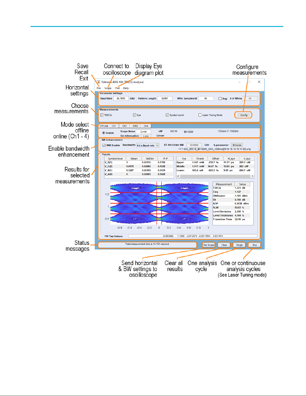
Display elements
Elements of the display............................................................................................ 5
Menu bar operations
File menu............................................................................................................ 7
Scope menu ......................................................................................................... 7
Plot menu............................................................................................................ 9
Help menu........................................................................................................... 9
Table of Contents
Horizontal Settings
Horizontal settings................................................................................................. 11
Measurement selections
Measurement selections........................................................................................... 13
Measurement configuration
TDECQ configuration........................................................................................ 13
Mode selection
Mode selection..................................................................................................... 17
Bandwidth enhancement
Bandwidth enhancement(BWE)................................................................................. 19
Set Scope
Set Scope button ................................................................................................... 21
Clear button
Clear button ........................................................................................................ 23
400G-M4 Printable Application Help i
Page 6

Table of Contents
Single
Single button....................................................................................................... 25
Run button
Run button.......................................................................................................... 27
Offline mode
Offline mode ....................................................................................................... 29
Online mode
Onlinemode........................................................................................................ 31
Results
Results elements................................................................................................... 33
Symbol l
Eye results.......................................................................................................... 34
TDECQ and PAM4 results ....................................................................................... 35
evel measurement....................................................................................... 34
Oscilloscope connection tips
Check network access............................................................................................. 37
ISA setup and troubleshooting............................................................................. 37
TekV
Firewall exceptions................................................................................................ 39
Remote control
Remotecontrol introduction...................................................................................... 41
Handshaking protocol............................................................................................. 41
tting up the PI environment.................................................................................... 42
Se
Variable:Value Commands
Syntax.......................................................................................................... 43
Variable name arguments and queries...................................................................... 44
Programming examples
Perl program example: configure and operate 400G-M4 ................................................ 59
Python example ............................................................................................... 61
Feedback
Feedback............................................................................................................ 63
Index
ii 400G-M4 Printable Application Help
Page 7

Introduction Welcom e
Welcome
The 400G-M4 analysis application provides PAM4 signaling analysis, including TDECQ (Transmitter
and Dispersion Eye Closure Quaternary) measurement. The application brings together PAM4 optical
measurement
TheapplicationisintendedtobeinstalledonaPCandcanoperateineitheroffline or online mode.
Offline mode: allows you to analyze a waveform file saved from the 80SJNB application (running on
the DSA8300 Digital Sampling Oscilloscope) or a waveform file saved from the 400G-M4 application
acquired f
Online mode: allows you to acquire directly from a connected DSA8300 Digital Sampling
Oscillos
NOTE. Online mode requires the installation of an option key on the target DSA8300 Digital Sampling
Oscilloscope to enable establishing a connection from the 400G-M4 application. Refer to the
documentation provided with the DSA8300 for instructions to add a new option key.
s in a simple and easy to use application.
rom a connected DSA8300 sampling oscilloscope.
cope and analyze acquired waveform data.
Key features
The 400G-M4 application performs comprehensive analysis of PAM4 signals, including TDECQ
measurements and other optical measurements.
400G-M4 provides the following features:
Show results as numeric and graphical display
Perform TDECQ (Transmitter and Dispersion Eye Closure Quaternary)
PAM4 signal characterization measurement such as level and eye measurements
ndard IEEE TDECQ Measurements (802.3bs, Section 121.8.5 and 802.3cd)
Sta
Acquire complete pattern waveform with user defined Samples/UI
Display 2-D eye diagrams
Save acquisition results to a data file
See also:
Computer requirements (see page 2)
DSA8300 sampling oscilloscope requirements (see page 2)
Option key (see page 3)
Online mode (see page 31)
400G-M4 Printable Application Help 1
Page 8

Introduction Computer requirements
Offline mode (see page 29)
Computer requirements
The 400G-M4 application is designed to run on a PC running the Windows operating system. A high
performance PC is recommended to minimize computation time to analyze the waveform data.
These are the minimum requirements to successfully run the 400G-M4 application. A PC with higher
performance results in faster measurements.
Operating system: Microsoft Windows 10 (64 bit) operating system.
Screen resolution: 1920 x 1080.
NOTE. Installing the 400G-M4 application directly on a DSA8300 Digital Sampling Oscilloscope is not
permitted.
Software requirements
The 400G-M4 application requires the following software to be installed onthePC.
TekVISA : TekVISA version 4.2.0.10 is recommended. Installation is available during 400G-M4
installation.
Matlab runtime: Matlab 2017b version 9.3 is required. The Matlab runtime is available from
MathWorks® (
https://www.mathworks.com).
See also:
TekVISA software (see page 3)
DSA8300 sampling oscilloscope requirements
The 400G-M4 application requires the following software to be installed on the connected DSA8300
sampling oscilloscope.
Scope Noise Characteristics: This application is provided with the 400G-M4 installation. It is a
separate installation file (bundled with the 400G-M4 download package) that is to be installed on the
connected DSA8300. This application enables the 400G-M4 application to automatically obtain the
scope noise value of the DSA8300.
The option key for the 400G-M4 application must be installed on the DSA8300 to which the
application connects for online mode of operation.
2 400G-M4 Printable Application Help
Page 9

Introduction TekVISA software
TekVISA software
TekVISA is preinstalled on the DSA8300 sampling oscilloscopes, but to use this protocol to connect
and communicate with a DSA8300 sampling oscilloscope, TekVISA must also be installed on the PC
(where the 40
TekVISA is available with the 400G-M4 application installation file or can be downloaded for free from
the Tektron
0G-M4 application resides).
ix website (www.tek.com
). Search for TekVISA Connectivity software.
Option key
To enable the 400G-M4 application to connect directly to a DSA8300 Digital Sampling Oscilloscope
(online m
Contact Tektronix to purchase a 400G-M4 option key.
Refer to the DSA8300 application help system for instructions to install option keys.
ode), the target DSA8300 must have a 400G-M4 option key installed.
Documentation
The application help system is available from the Help menu.
In addition to the help system, a printable version of the Help is provided as a PDF in the following folder:
C:\Users\Public\Tektronix\TekApplications\400G-M4.
400G-M4 Printable Application Help 3
Page 10

Introduction Documentation
4 400G-M4 Printable Application Help
Page 11
Display elements Elements of the display
Elements of the display
400G-M4 Printable Application Help 5
Page 12

Display elements Elements of the display
6 400G-M4 Printable Application Help
Page 13

Menu bar operations File menu
File menu
The file menu provides the following operations:
Table 1: File menu
Setting Description
Save Waveform Saving waveforms is only available when using the online mode.
You can save the acquired waveform (or waveforms if multiple channels are enabled) from the
connected DSA8300 oscilloscope. A dialog screen opens to allow you to navigate to name and
save the waveform.
Use the dialog screen to provide a base filename. The filename will be appended with the channel
source of the w aveform.
Save Setup Use the dialog screen to navigate to a location to save the setup file to recall at a later time. Setup
files use a file extension of .gm4.
Setup files contains the following information:
■ Horizontal settings
■ Measurement selections
■ All measurement configuration settings
■ Offline setting
■ FFE tap values
■ Measurement results
■ BWE settings
Setup files do not save information relating to the oscilloscope or modules, such as:
■ Scope IP address
■ Scope Noise
■ Vertical setting
■ Channels enabled
■ Module related information
■ External attenuation
Recall Setup Use the dialog screen to navigate to a saved setup file to restore the application to a known setup.
Exit Exits the application.
xxx
NOTE. The File menu operations are unavailable if a n analysis is currently running.
Scope menu
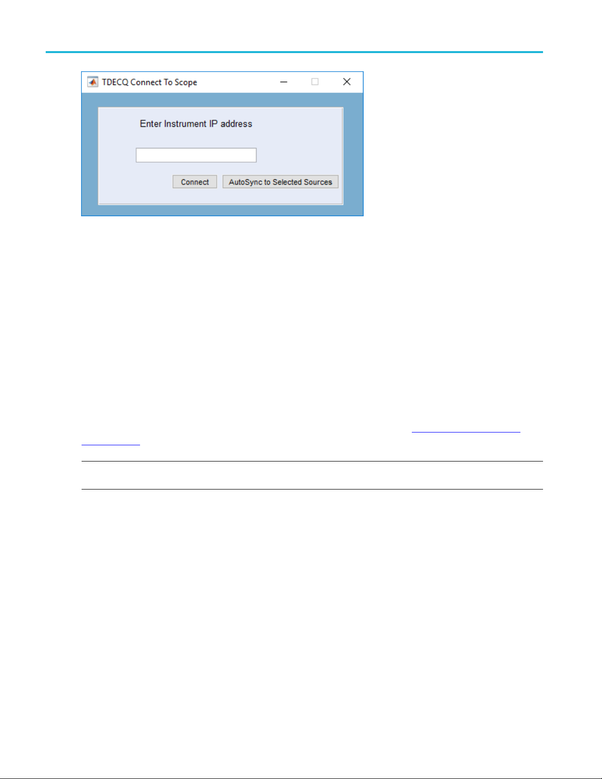
Selecting Scope opens the TDECQ Connect To Scope dialog screen.
400G-M4 Printable Application Help 7
Page 14
Menu bar operations Scope menu
Enter the IP address or the computer name of the oscilloscope you want to connect to. The IP address
can be found by viewing the Windows network connection status. The computer name can be found in
the System properties.
Connect. Select the Connect button to make the connection. (The Connect button changes to Disconnect
if a conn
The Status area at the bottom of the main screen also indicates a successful connection.
ection is established.)
AutoSync to Selected Sources. During the connection process, the 400G-M4 application detects the
modules installed in the oscilloscope along with their characteristics (such as the module type, serial
number, filters or bandwidth). If you change a module or change a module’s characteristics, use the
AutoSync to Selected Sources button to easily update the 400G-M4 application without having to
reconnect.
If you are having difficulty connecting to your oscilloscope, see the section Connection help and tips
(see page 37).
E. The 400G-M4 application can only connect to one DSA8300 Digital Sampling Oscilloscope at a
NOT
time.
8 400G-M4 Printable Application Help
Page 15
Menu bar operations Plot menu
Plot menu
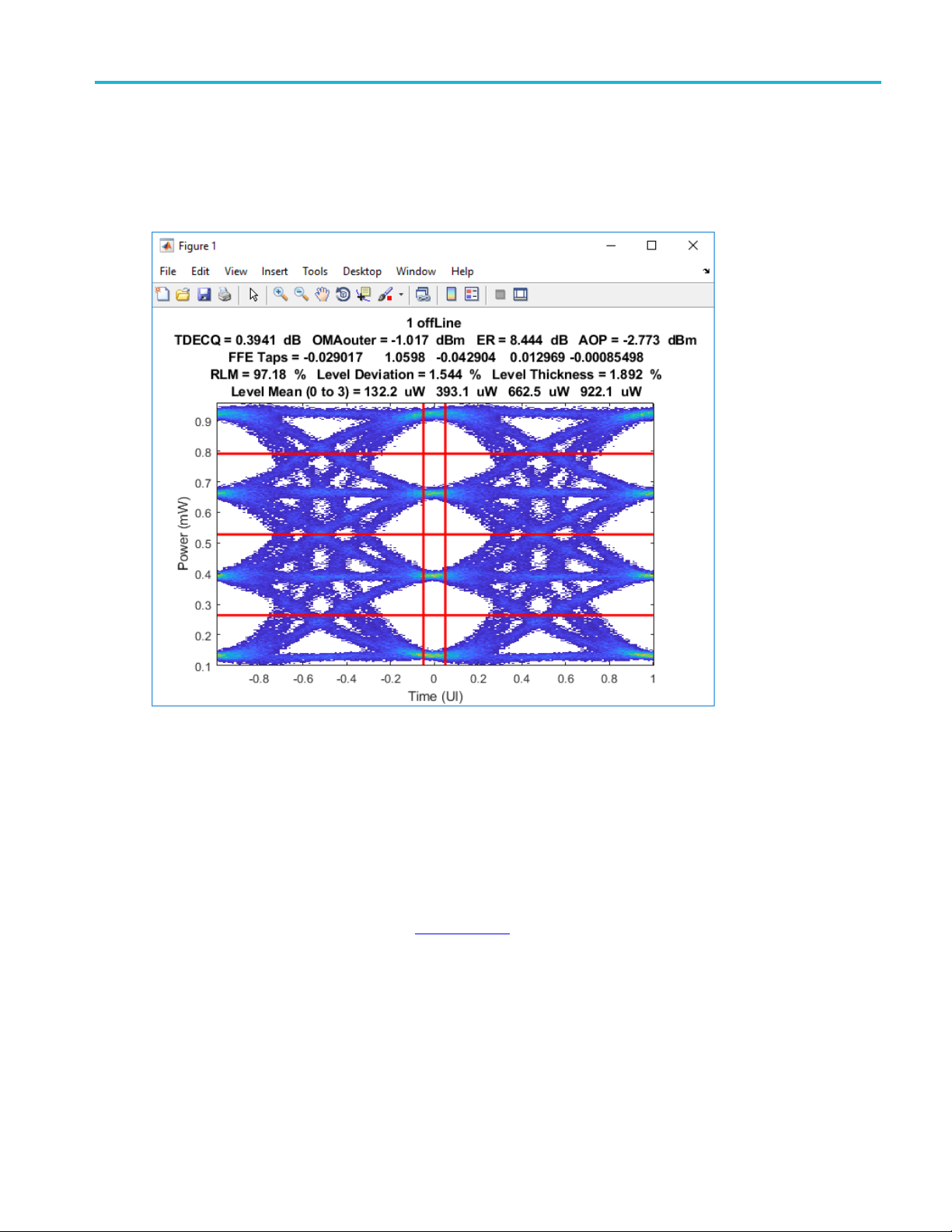
The Plot menu allows you to open the TDECQ eye plot display in Matlab.
Help menu
In addition to accessing the application help system, use the help button to obtain the application software
version number.
This can help when contacting Tektronix about the application and to check if there are newer versions
available from the Tektronix website (www.tek.com
A printable version of the help system is provided as a PDF in the following folder:
\Program Files\TekApplications\400G-M4.
C:
400G-M4 Printable Application Help 9
).
Page 16

Menu bar operations Help menu
10 400G-M4 Printable Application Help
Page 17

Horizontal Settings Horizontal settings
Horizontal settings
The horizontal settings are only applicable when using the online mode (connected to an oscilloscope).
The settings are global for all online channels. In offline mode, these settings are automatically extracted
from the wave
Set the values as appropriate for the type of optical signal you are analyzing.
Table 2: Horizontal settings
Setting Description
Baud Rate
Pattern Length
Wfm Samples/UI Enter the number of waveform samples per user interval.
Avg
form file.
Enter the GigaBaud rate of the signal you intend to acquire.
Enter the Pattern Length of the signal you intend to acquire.
When enabled, enter the # of Wfms of to acquire. The acquired waveforms are then averaged
together into a single waveform.
Use the File –> Save Waveform to save the averaged waveform.
#ofWfms
(Only available for
live channels)
xxx
NOTE. When Averaging waveforms, no measurements are performed.
With the Avg box enabled, enter the number of waveforms to average from the acquisition (not
available for TDECQ measurements).
Range: 1 to 1000.
400G-M4 Printable Application Help 11
Page 18

Horizontal Settings Horizontal settings
12 400G-M4 Printable Application Help
Page 19

Measurement selections Measurement selections
Measurement selections
The measurement selection includes all the available optical measurements.
The selected measurements apply to the offline mode (file analysis) and to the online mode for all channels.
Table 3: Measurement selections
Measurements Description
TDECQ Includes the following measurements to the results section.
■ TDECQ: Transmitter and dispersion eye closure for PAM4 defined by IEEE 802.3bs (draft 3.5,
dated 10-October-2017).
■ OMAouter: The outer Optical Modulation Amplitude.
■ ER: The extinction ratio of the highest and lowest optical power levels of a PAM4 optical signal.
■ AOP: The average optical power of a PAM4 optical signal.
Eye
Symbol Level Includes all the Symbol level measurement results.
Laser Tuning
Mode
xxx
Includes the following measurements to the results section.
■ RLM: Level separation mismatch ratio.
■ Level Deviation: The average deviation of level spacing from the ideal spacing.
■ Level Thickness: The averaged, normalized level standard deviation at minimum inter-symbol
interference.
■ The Threshold/Offset/Horizontal Eye (H_eye)/Vertical Eye (V_eye) for each PAM4 eye.
■ Symbol Levels: Provides the Mean, Standard Deviation, and Pk-Pk values of the V_D(3), V_C(2),
V_B(1), V_A (0) s ymbol levels.
Laser Tuning Mode changes the operation of the application to enable you to quickly adjust your
laser settings while acquiring data.
When enabled, two changes to operation take effect:
■ Pressing the Run button starts a continuous analysis cycle.
To run a single analysis, you must use the Single button.
■ Some measurements such as symbol levels and RLM run much faster (but with slightly less
accuracy).
ECQ c on figuration
TD
e measurement configuration allows you to further define the TDECQ measurement and adjust the
Th
Extinction Ratio results.
400G-M4 Printable Application Help 13
Page 20

Measurement selections TDECQ configuration
Table 4: Measurement configuration
TDEQ Con figuration
FFE taps
FFE Taps/UI Enter the number of taps per unit interval (symbol) for FFE. The range of the value is 1 – 10.
Max Pre-Cursors Enter the maximum number of pre-cursor taps for FFE. The value must be less than the number of
nded Search
Exte
Vertical Threshold
ust
Adj
toset Tap Values
Au
Enter the number of taps. The number of taps must be an odd value.
ps.
FFE ta
is disabled by default.
This
When enabled, the algorithms perform an extended search for the optimal FFE taps to minimize the
TDECQ value (but increases the time to complete).
disabled, the FFE taps are adapted faster but may be less optimal.
When
s is enabled by default.
Thi
When enabled, the sub-eye threshold levels are allowed to adjust by ± 1% of the OMAouter. IEEE
802.3cd allows this option to be selected for TDECQ measurements.
en disabled, the sub-eye threshold levels are determined by OMAouter and the average optical
Wh
power.
When enabled, the application automatically calculates optimized FFE taps to minimize the TDECQ
value.
hen disabled, the current FFE taps are used. You can manually input the FFE tap values via the
W
FFE Tap Values area at the bottom of the application main screen.
This is enabled by default.
14 400G-M4 Printable Application Help
Page 21

Measurement selections TDECQ configuration
Table 4: Measurement configuration (cont.)
TDEQ Configuration
Auto Import Scope
Noise
Recalculate Taps
ER Adjust
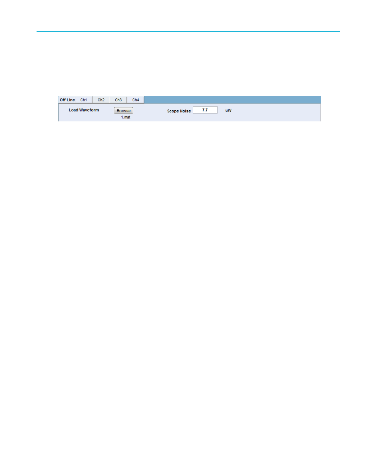
Off Line
Ch1 – Ch4
xxx
This is enabled by default.
When enabled, the application automatically retrieves the measured oscilloscope noise from the
connected DSA8300 oscilloscope when in online mode.
The Scope Noise Characteristics application must be i nstalled and run prior to importing the
oscilloscope noise.
This is disabled by default.
When enabled, the application recalculates taps at every run when Autoset Tap Values is On. This
uses the FFE tap seed from the previous calculation or recalculates a new one. You can save the
measurement time by using the FFE tap seed from the previous calculation.
ER Adjust allows you to add or subtract a specified percentage from the measured extinction ratio
value, adjusting for a better m atch between multiple oscilloscopes.
This can be set individually for Off Line mode and each individual channel when in online mode.
400G-M4 Printable Application Help 15
Page 22

Measurement selections TDECQ configuration
16 400G-M4 Printable Application Help
Page 23

Mode selection Mode selection
Mode selection
The mode selection allows you to either analyze a saved data file (offline mode) or make a live acquisition
(online mode) directly from one (or all) of the four optical channel selections available on the DSA8300.
The offline mode requires you to navigate to a saved data file for analysis.
The online mode requires a connection to a DSA8300 oscilloscope.
The instrument acquisition status during the measurement process in a live acquisition is
displayed in the Acquisition_statusFile.txt. This file is located in the directory “C:\Users\<user
name>\AppData\Local\Temp”. The file lists the instrument state as either Idle or Acquire. When in Idle,
aninstrumentcanbeusedbymore than one application at a time.
For more information, see the topics Offline mode
(see page 29) and Online mode (see page 31).
400G-M4 Printable Application Help 17
Page 24

Mode selection Mode selection
18 400G-M4 Printable Application Help
Page 25

Bandwidth enhancement Bandwidth enhancement (BWE)
Bandwidth enhancement (BWE)
Bandwidth enhancement can be used whether analyzing a saved file (offline mode) or when connected to
an instrument (online mode). The feature operates the same for either mode.
When using in online mode, the feature can be enabled or disabled independently for each channel.
Table 5: Measurement configuration
Item Description
BWE Enable
Bandwidth
BT 4th Order BW Enter the Bessel -Thomson reference receiver filter when the Bandwidth is set to User.
S-parameter You can load a scattering parameter (S-parameter) file that characterizes the optical sampling
Enables the bandwidth enhancement feature for the selected file (Offline mode) or the channel
(Online mode).
The Bandwidth Enhancement controls allow you to use DSP processing to achieve more accurate
oscilloscope channel response. For example, the BWE can make the oscilloscope channel response
to be ORR compliant even if the hardware is not.
Select the bandwidth filter to use during the analysis.
■ HW only: uses the instrument hardware.
■ 0.5 Baud rate: sets the bandwidth of the 4th order Bessel-Thomson filter to be 0.5 × Baud Rate.
■ 0.75 Baud rate: sets the bandwidth of the 4th order Bessel-Thomson filter to be 0.75 × Baud Rate.
■ User: This allows a user to dial in the bandwidth of a 4th order 4th order Bessel-Thomson filter.
module available for the DSA8300.
NOTE. An S-parameter file is supplied with the 80C20 and 80C21 optical sampling modules.
These files are unique to each module.
Use the Browse button to navigate to a saved S-parameter file. The S-parameter file name contains
the module type, serial number, and hardware filter information.
xxx
400G-M4 Printable Application Help 19
Page 26

Bandwidth enhancement Bandwidth enhancement (BWE)
20 400G-M4 Printable Application Help
Page 27

Set Scope Set Scope button
Set Scope button
The Set Scope button simplifies the setup of the connected oscilloscope.
When Set Scope is pressed, the application sets several of the oscilloscope’s horizontal and vertical
settings that are appropriate for the chosen baud rate.
The BW Enhancement settings (except for S-parameters) are also set in the 400G-M4 application.
400G-M4 Printable Application Help 21
Page 28

Set Scope Set Scope button
22 400G-M4 Printable Application Help
Page 29

Clear button Clear button
Clear button
The Clear button removes all measurement results, including the TDECQ plotdisplay.
400G-M4 Printable Application Help 23
Page 30

Clear button Clear button
24 400G-M4 Printable Application Help
Page 31

Single Single button
Single button
Press the Single button to run one acquisition and analysis cycle. At least one measurement must be
selected.
The analysis cycle includes acquiring waveforms and performing the selected measurements.
NOTE. The Single button allows you to runs a single analysis cycle when in Laser Tuning Mode. When
Laser Tunin
than a single analysis).
g is enabled, pressing the Run button puts the analysis cycle into a continuous mode (rather
When in on
line mode, a connection must be established to a DSA8300, containing supported modules.
400G-M4 Printable Application Help 25
Page 32

Single Single button
26 400G-M4 Printable Application Help
Page 33

Run button Run button
Run button
Press the Run button to start an analysis cycle. At least one measurement must be selected.
The analysis cycle includes acquiring waveforms and performing the selected measurements.
The action of the Run button changes depending on the status of the Laser Tuning Mode.
Laser Tuning Mode:
Disabled: A
Enabled: The analysis and measurement cycle runs continuously until stopped. (In this mode, the
Run button
See Laser Tuning Mode in Measurement selections
actions.
When in offline mode, a file must be loaded before pressing the Run button.
When in online mode, a connection must be established to a DSA8300 containing supported modules.
single analysis cycle is run.
changes to Stop. Press Stop to end the analysis cycle.)
(see page 13) for details of the measurement
400G-M4 Printable Application Help 27
Page 34

Run button Run button
28 400G-M4 Printable Application Help
Page 35
Offline mode Offline mode
Offline mode
Using the application in Offline mode simply means you can analyze a saved waveform file without
connecting to a sampling oscilloscope.
Click the Off Line tab and use the Browse button to navigate to waveform file (saved from the 80SJNB
application or the 400G-M4 application) for analysis.
TDECQ measurement requires the input of scope noise, σs, defined as the standard deviation of the noise
of the optical probe and oscilloscope combined. It is calibrated with no optical input signal and the same
settings used to capture the optical signal, after the application of applicable ORR.
Loading a waveform file automatically inputs the scope noise value associated with the loaded file
if available.
Once the file is loaded, select the measurements you want returned, and then press the Run button. The
various result panels will be populated based on the selected measurements.
400G-M4 Printable Application Help 29
Page 36

Offline mode Offline mode
30 400G-M4 Printable Application Help
Page 37

Online mode Online mode
Online mode
Online mode allows you to acquire waveforms directly from the connected oscilloscope, analyze the
data, and display the results. (A connection to the oscilloscope must be made prior to selecting the Run
button. See t
The 400G-M4 application currently supports the following optical modules (installed in a DSA8300
mainframe):
80C17
80C18
80C20
80C21
80C10C
NOTE. If you would like to use a non-supported module, add it to "SupportedModules.xml" file located in
the installation directory. Performance and measurement accuracy are not guaranteed for non-supported
modules.
he Scope menu
(see page 7).)
Selecting any of the channel tabs enters the Online mode.
With a channel tab open, select Enable to enable acquiring waveforms from that channel of the
oscilloscope. With a connection established, the information about the optical module installed in that
channel is displayed.
NOTE. If the module installed in the channel is not supported, the Enable button is inactive.
There are four channels available on the DSA8300 oscilloscope. You can enable any number of channels.
Each channel must be enabled in its channel tab.
TDECQ measurement requires the input of scope noise, σs, defined as the standard deviation of the noise
of the optical probe and oscilloscope combined. It is calibrated with no optical input signal and the same
settings used to capture the optical signal, after the application of applicable ORR. You must set the scope
noise value for each channel intended to use for testing. This value can be automatically imported from the
connected DSA8300. See Scope Noise auto import below.
Whentheanalysisisstarted,thewaveforms are acquired from each enabled channel. If one channel
calculation is aborted during the live channel measurement, the rest of the channel calculations continue.
400G-M4 Printable Application Help 31
Page 38

Online mode Online mode
The scope front panel is locked when data acquisition starts. The front panel is unlocked when acquisition
is complete.
The results displayed are for the current channel. Use the channel tabs to display the results for each
channel.
Scope noise auto import
The Scope No
are met:
The Scope N
The Scope Noise Characteristics application had been run on the DSA8300 (with modules installed)
prior to s
The Measurement Configuration must have Auto Import Scope Noise enabled.
ise value can be imported directly from the connected DSA8300 if the following conditions
oise Characteristics application must be installed on the connected DSA8300.
tarting the analysis cycle of the 400G-M4 application.
External attenuation
al attenuation can be applied to the scope channel input signal. The external attenuation units are set
Extern
by the DSA8300 and can be either Linear or dB.
32 400G-M4 Printable Application Help
Page 39

Results Results elements
Results elements
The results area is populated with the latest measurements from the latest analysis. The areas populated
with results depend on the selected measurements to make during analysis.
When in offline mode, the results display the measurements for the waveform file loaded.
When in online mode, the results displayed are for the selected channel tab. Use the channel tabs to
see results for the various channels. (There are no results for a channel if the channel was not enabled
prior to starting the analysis.)
Capturing results
You can reduce test time by using the TDECQ_ResultsFile.txt file that is saved in C:\Users\<user
name>\\AppData\Local\Temp. Measurement results are captured in this file, which allows you to access
l of the measurement results in a single file instead of querying results one at a time. Note that “ERROR”
al
will show if the measurement has errors.
e following is a TDECQ example TDECQResults.txt for an offline channel case:
Th
400G-M4 Printable Application Help 33
Page 40

Results Symbol level measurement
"offLine:TDECQ","0.87886","offLine:TDECQMeasIsInQuestion","0","offLine:OMA","-
3.8533","offLine:ER","5.4282","offLine:AOP","-4.3916",
Symbol level measurement
When the Symbol Level measurement is selected, the Symbol Levels result area is populated for the
following four symbol levels. An Eye plot will show after the measurement even if TDECQ is not checked.
V_D(3): For the top symbol level, this is the voltage at the center of the unit interval across all
instances of symbol 3s in the complete waveform. The mean, standard deviation and peak-to-peak
range are s
V_C(2): Same as V_D(3), except for the symbol 2's.
V_B(1): Same as V_D(3), except for the symbol 1's.
V_A(0): Same as V_D(3), except for the symbol 0's.
hown. Only the mean value is used in the computation of RLM .
Table 6
Result Descri
Mean
Stand
P-P
xxx
:
ard deviation
Eye results
When the Eye measurement is selected, the Eye result area is populated with the eye measurements for
all three eye openings (Upper, Middle, Lower).
ble 7:
Ta
sult
Re
Threshold
ffset
O
H_eye (Width) The eye width of the corr esponding (upper, middle or lower) eye.
V_eye (Height) The eye height of the corresponding (upper, middle or lower) eye.
xxx
ption
Mean va
Stand
Peak-
De
Th
T
rendered, at the corresponding reference voltage.
lue (watts) of the measurements.
ard deviation of the measurements.
to-peak value of the measurements.
scription
e reference voltage levels for each PAM4 TDECQ eye.
he horizontal offset, in time, from the center of the sub-eye to the measured center of the eye as
34 400G-M4 Printable Application Help
Page 41

Results TDECQ and PAM4 results
TDECQ and PAM4 results
When the TDECQ measurement is selected, the TDECQ result is provided along with various PAM4
measurements.
Table 8:
Result Description
TDECQ As defined by IEEE 802.3bs, Section 121.8.5 and 802.3cd.
Ceq Equalizer noise enhancement coefficient.
NOTE. TDECQ – 10log10(Ceq) measurement can be calculated from TDECQ and Ceq values.
OMAouter Outer Optical Modulation Amplitude, reported in dBm.
ER Extinction Ratio
AOP Average Optical Power
The average power of a PAM4 optical signal, reported in dBm.
RLM Level separation mismatch ratio.
FFE taps
Level Deviation
Taps for the Feed-Forward Equalizer (FFE).
A measure of the deviation of the vertical intervals between levels from perfectly equal spacing,
where 0% represents perfect spacing.
The measurement is computed as:
el Thickness
Lev
Transition Time
xxx
An overall measure of the vertical thickness of the symbol levels in the correlated waveform, where
an ideal signal with maximally open eyes would have a thickness of 0%.
e measurement is computed as:
Th
Transmitter transition time is defined as the slower of the following:
■ The time interval of the transition from 20% of OMAouter to 80% of OMAouter (rising edge).
■ The time interval of the transition from 80% of OMAouter to 20% of OMAouter (falling edge).
400G-M4 Printable Application Help 35
Page 42

Results TDECQ and PAM4 results
36 400G-M4 Printable Application Help
Page 43

Oscilloscope connection tips Check network access
Check network access
The first step to troubleshoot a connection problem is to check the network access.
Ensure that the DSA8300 is connected to the network, and the TekScope application is running.
TekVISA setup and troubleshooting
Verify that TekVISA is installed on the PC.
TekVISA is required to be running on both the PC and the target oscilloscope.
Look for t
If other VISA software is installed on the PC, verify that TekVISA is the default VISA. Use the
OpenCho
program folder).
he TekVISA icon in task bar.
ice VISA64 Conflict Manger (available in the list of applications under the Tek VISA
Make sure that the instrument is detected in the TekVISA Open Choice Instrument Manager (available
in the list of applications under the TekVISA program folder).
400G-M4 Printable Application Help 37
Page 44

Oscilloscope connection tips TekVISA setup and troubleshooting
To detect an instrument for through TekVISA, select the Search Criteria button and then select LAN.
Search o
n the IP address.
Make sure that the VXI-11 server under TekVISA LAN Server is started on the DSA8300. The server
is turned off after the instrument is rebooted, so user needs to start it manually.
38 400G-M4 Printable Application Help
Page 45
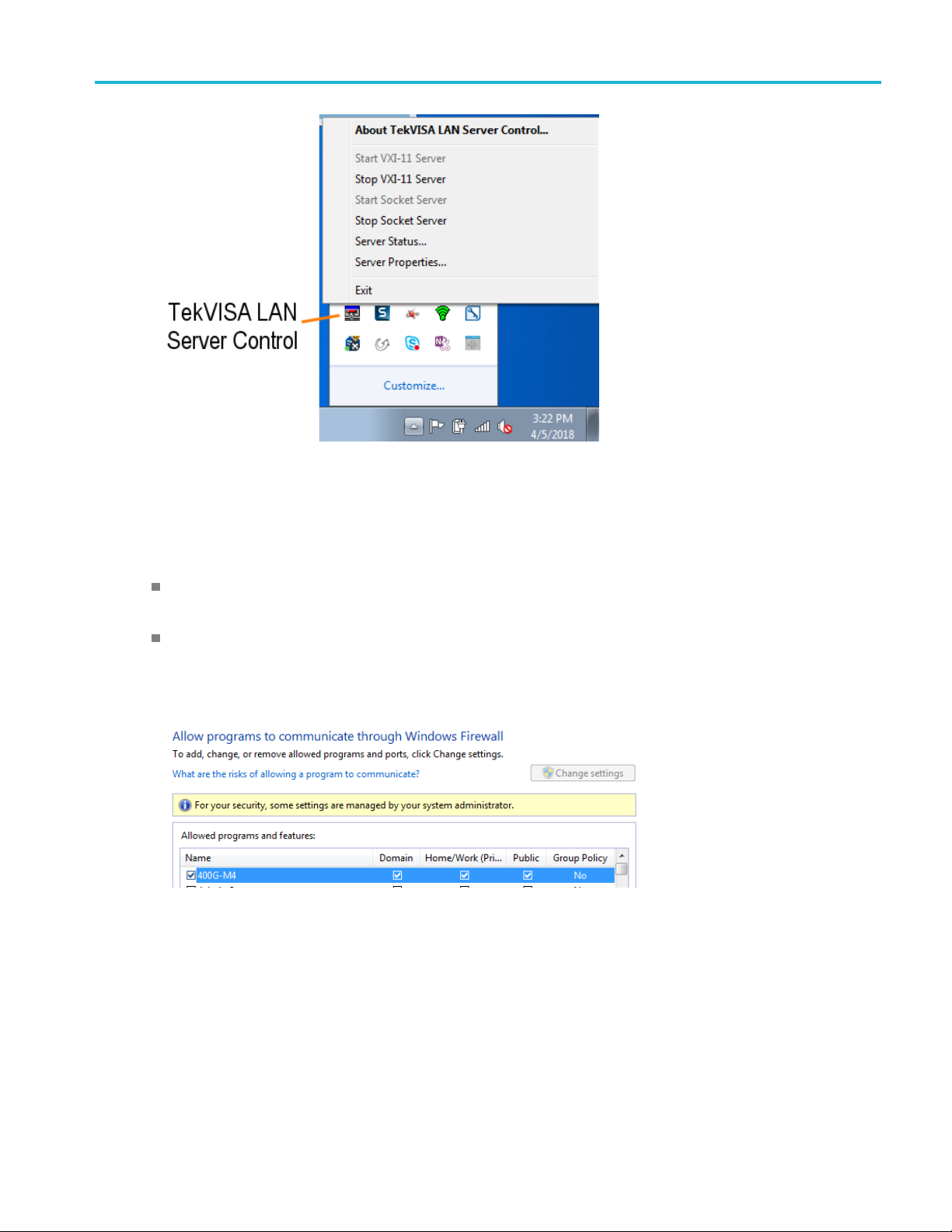
Oscilloscope connection tips Firewall exceptions
Firewal
l exceptions
Make sur
both the DSA8300 instrument and the PC running 400G-M4 application.
Make su
Open the "Windows Firewall" from "Control Panel" and follow instructions under "Allow an app or
featu
e that TekVISA inbound and outbound traffic are allowed through the Windows Firewall on
re that 400G-M4 application is added to the Windows Firewall exception listonthePC.
re through Windows Firewall".
400G-M4 Printable Application Help 39
Page 46

Oscilloscope connection tips Firewall exceptions
40 400G-M4 Printable Application Help
Page 47

Remote control Remote control introduction
Remote control introduction
The 400G-M4 software application can be controlled programmatically through the programmatic
interface. Communication with the application is accomplished using VARIABLE:VALUE remote GPIB
commands.
For information on how to operate the sampling oscilloscope and use its application-specific GPIB
commands, r
Your program should comply with the following guidelines:
The application startup must complete before sending additional GPIB commands to the application.
The measurements cycle must complete before you query data.
See also:
Variable:Value Commands (see page 43)
Program example configure and operate the 400G-M4 (see page 59)
efer to the programmers guide for your sampling oscilloscope.
Handshaking protocol
The application handles GPIB communications through its own protocol handshaking.
The requirements for GPIB communications with a controller are as follows:
1. Once
2. The
3. Th
4. The application GPIB function polls the handshake variable, reads the command string and interprets it
5. A good command is parsed and executed. On successful execution, the application writes an OK to the
the application has started, it writes an "OK" status to the application handshake variable. This
tells the controller that it may now write a valid command into the "tdecq" variable.
GPIB controller polls the handshake variable (VARIABLE:VALUE? "tdecq") until it detects the
OK status.
e GPIB controller writes a command string into the application handshake variable. For example,
sending the command VARIABLE:VALUE "tdecq", "single" writes the string "single" into the
variable "tdecq".
as a command. If the command is not understood, it writes an ERROR handshake value to the variable.
handshake variable. When the GPIB controller reads the OK status, it may send a new command string.
400G-M4 Printable Application Help 41
Page 48

Remote control Setting up the PI environment
Setting up the PI environment
To help users get started with using GPIB commands to operate the 400G-M4 Analysis application,
examples of automatic testing script written in Perl and Python 3.5 is included. These are examples only.
Users are fre
is followed.
StartClientwithPerl
The prerequisites are:
Matlab runtime needs to be installed and in the user’s path
e to use any programming language of their choice as long as the handshaking protocol
Perl v5.2
When the 400G-M4 is running, you can start the client with the following Perl script.
perl TDECQ_PI_Client.pl
When the 400G-M4 is not running, the script needs to start the 400G-M4 as well as set up the environment
by using:
perl TDECQ_PI_Client.pl –startApp
NOTE. You may need to use the –filePath “<pathToTDECQexe>” to tell the client where to connect
to the currently running Applications’ process.
4.3 or later needs to be installed and in the user’s path
Start Client with Python
prerequisites are:
The
Matlab runtime needs to be installed and in the user’s path
Python 3.5 or above needs to be installed and in the user’s path
When the 400G-M4 is running, you can start the client with the following Python script.
python TDECQ_PI_Client.py
When the 400G-M4 is not running, the script needs to start the 400G-M4, as well as set up the environment
by using:
NOTE. You may need to use the -filePath “<pathToTDECQexe>” to tell the client where to connect
to the currently running Applications’ process.
42 400G-M4 Printable Application Help
Page 49

Remote control Syntax
Running Multiple Instances
Use the following to start the main UI program with assigned instance id of <instanceId>. The default
<instanceId> is 1. See the Example Main Program Execution
400G-M4.exe <instanceId>
(see page 60) for more details and examples.
Running Using TCP/IP Address
For an IP connect, use the following command
perl TDECQ_PI_Client.pl -cmdfilepath=\\ip address\c$\Program Files\TekApplications\400G-M4
This starts 400G-M4.exe at C:\Program Files\TekApplications\400G-M4\400G-M4.exe. The TCPIP
requires that the C: drive on the target running the 400G-M4 application is publicly accessible. In the
example, it shares as "c$".
Reducin
You can reduce test time by using the TDECQ_ResultsFile.txt file that is saved in C:\Users\<user
name>\
all of the measurement results in a single file instead of querying results one at a time. Note that “ERROR”
will show if the measurement has errors.
The following is a TDECQ example TDECQResults.txt for an offline channel case:
Syntax
The VARIABLE:VALUE command accepts string arguments for a control or data variable and a value
to
To set a variable to a value, use the syntax:
For example, the following commands sets the BWE mode to ON.
g test time
\AppData\Local\Temp. Measurement results are captured in this file, whichallowsyoutoaccess
Line:TDECQ","0.87886","offLine:TDECQMeasIsInQuestion","0","offLine:OMA","-
"off
3.8533","offLine:ER","5.4282","offLine:AOP","-4.3916",
which to set the argument.
VARIABLE:VALUE "tdecq”,"<variableName>:<variableValue >"
VARIABLE:VALUE "tdecq","bwe:on"
To query the value in a variable:
VARIABLE:VALUE? "tdecq","<variableName>"
For example, the following command queries the state of the BWE mode.
VARIABLE:VALUE? "tdecq","bwe"
400G-M4 Printable Application Help 43
Page 50

Remote control Variable name arguments and queries
NOTE. The arguments <variableName> and <variableValue> are required in the order indicated, no
spaces, and use of proper capitalization.
Your program will not operate correctly if you do not follow these requirements.
See also:
Variable:Value Command Arguments and Queries (see page 44)
Program example configure and operate 400GM4 (see page 59)
Variable name arguments and queries
Table 9: Control commands and queries
Commands Description
:variable:value "tdecq","activate:<NR1>"
Syntax
Example
:variable:value? "tdecq","attunit:ch1"
Syntax :variable:value? "tdecq",” attunit:ch1"
Example :variable:value? "tdecq","attunit:ch1" might return dB.
Return Examples
:variable:value?
"tdecq","attvalue:ch1"
Syntax :variable:value? "tdecq","attvalue:ch1"
Command only.
Starts the 400G-M4 application.
Required before any further processing or setup commands can be executed.
Use the command :variable:value? "tdecq","instanceId" to return the instance ID.
:variable:value "tdecq","activate:<NR1>"
<NR1> = instance ID.
:variable:value "tdecq","activate" starts the 400G-M4 application.
Query only.
Returns the external attenuation unit (Linear or dB) for CH1.
Returns: $response = ‘Linear’
Returns: $response = ‘dB’
Returns: $response = ‘None’ means that CH1 is not connected.
Query only.
Returns CH1 external attenuation value.
Example
Return Example
:variable:value? "tdecq","attvalue:ch1" returns the CH1 external
attenuation value.
Returns: $response = ‘1’
44 400G-M4 Printable Application Help
Page 51

Remote control Variable name arguments and queries
Table 9: Control commands and queries (cont.)
Commands Description
:variable:value? "tdecq",
"config:recalctapvalues?"
Syntax :variable:value? "tdecq","config:recalctapvalues?"
Example
Return Example
:variable:value? "tdecq","instanceId"
Syntax :variable:value? "tdecq","instanceId"
Example :variable:value? "tdecq","instanceId" returns the ID.
Return Example
:variable:value "tdecq","connect:<ip_address>"
Query only.
Enables the FFE taps recalculation.
:variable:value? "tdecq","config:recalctapvalues?" returns
the recalculated FFE taps values.
Returns: $response = '1 '
1 indicates the Recalculate taps box is checked.
0 indicates the Recalculate taps box is unchecked.
Query only.
Returns the instance ID.
Returns: $response = ‘1’
The set form provides the IP address or the computer name of the oscilloscope to
connect to the application.
The query form returns the IP address of the connected oscilloscope if it exists.
Make sure TekVISA is turned on and the instrument can be found via the TekVisa
before setting the IP address.
For help with connection issues, refer to Oscilloscope connection tips
(see page 37).
Syntax
Example :variable:value "tdecq","connect:134.62.9.4" connects to the
Return Example
:variable:value "tdecq","disconnect"
Syntax
Example :variable:value "tdecq","disconnect" disconnects the application
:variable:value? "tdecq","online"
:variable:value "tdecq","connect:<ip_address>"
instrument with the given IP address.
:variable:value? "tdecq","connect" returns the IP address of a
connected instrument.
Returns: $response = ’134.62.9.4'
Command only.
Disconnects the application from the oscilloscope in online mode (returns to offline
mode).
:variable:value "tdecq","disconnect"
from the connected oscilloscope.
Query only.
Checks if the application is connected to an oscilloscope and has a valid license.
400G-M4 Printable Application Help 45
Page 52

Remote control Variable name arguments and queries
Table 9: Control commands and queries (cont.)
Commands Description
Syntax :variable:value? "tdecq","online"
Example
Return Example
:variable:value "tdecq","autosync"
Syntax
Example
:variable:value "tdecq","analyze"
:variable:value? "tdecq","online" verifies an oscilloscope connection
and a valid license.
Returns: $response = '1' indicates connected.
Returns: $response = '0' indicates no connection.
Command only.
Loads the module information from the connected oscilloscope (when in online mode).
Use this command to re-sync module information if any changes have been made to
the modules after the initial connection to the oscilloscope.
See queries for "various module data fields" to retrieve module information after
sending this command.
:variable:value "tdecq","autosync"
:variable:value "tdecq","autosync" synchronize the module information
with the application.
Command only.
Starts the analysis measurements on the currently loaded data. This is equivalent to
pressing the "Run" button.
This is required before querying any measurement results.
NOTE. After analysis is complete, results of all active channels are also available in
%TEMP%\TDECQ_ResultsFile.txt. For TDECQ instances other than the default,
results are written to %TEMP%\TDECQ_ResultsFile<instanceId>.txt.
Syntax
Example :variable:value "tdecq","analyze" starts the analysis process.
:variable:value "tdecq","clear"
Syntax
Example :variable:value "tdecq","clear" clears all result measurements.
:variable:value? "tdecq","status"
Syntax :variable:value? "tdecq","status"
Example
Return Example
:variable:value "tdecq","analyze"
Command only.
Clears all measurement results.
:variable:value "tdecq","clear"
Query only.
Returns the contents of the status line.
:variable:value? "tdecq","status" returns the current string from
the status line.
Returns: $response = 'No waveform File'
46 400G-M4 Printable Application Help
Page 53

Remote control Variable name arguments and queries
Table 9: Control commands and queries (cont.)
Commands Description
:variable:value "tdecq","exit"
Command only.
Exits the 400G-M4 application.
If and analysis is in process, the program exits after the analysis is complete.
Syntax
Example
:variable:value "tdecq","recallsetup:C:\Users\Public\Tektronix\TekApplications\400G-M4\test.gm4"
:variable:value "tdecq","exit"
:variable:value "tdecq","exit" exits the 400G-M4 application.
Command only.
Recalls the 400G setup file.
(Read about what information is saved in setup files in the table in the File menu
page 7) topic.)
Syntax :variable:value "tdecq","recallsetup:C:\Users\Public\Tektronix\TekApplications\
400G-M4\test.gm4"
Example
:varia
lic\Tektronix\TekApplications\ 400G-M4\test.gm4"
ble:value? "tdecq","recallsetup:C:\Users\Pub-
test.gm4 setup.
iable:value
:var
"tdecq","savesetup:C:\Users\Public\Tektronix\TekApplica-
s\400G-M4\test.gm4"
tion
Command only.
Saves the 400G setup to a *.gm4 file.
d about what information is saved in setup files in the table in the File menu
(Rea
page 7) topic.)
(see
recalls the
(see
Syn
tax
riable:value "tdecq","savesetup:C:\Users\Public\Tektronix\TekApplications\
:va
400G-M4\test.gm4"
Example
:variable:value? "tdecq","savesetup:C:\Users\Public\Tektronix\TekApplications\400G-M4\test.gm4"
test.gm4.
:variable:value "tdecq","savewaveform:<filename>"
Command only.
Saves the acquired live channel waveform into filesforch1toch4. Thefiles are saved
in the specified directory.
Syntax :variable:value "tdecq","savewaveform:<filename>"
<filename> must include the filepath and filename.
Example
:variable:value "tdecq","savewaveform:c:\test\waveform"
saves the file named “waveform” to the specified directory.
:variable:value
"tdecq","savesetup:<setupname>"
Command only.
Saves the current settings to a setup file. The setup file is saved in the specified
directory.
Setup files use the file extension .gm4.
saves a 400G setup as
400G-M4 Printable Application Help 47
Page 54

Remote control Variable name arguments and queries
Table 9: Control commands and queries (cont.)
Commands Description
Syntax
:variable:value "tdecq","savesetup:<setupname>"
<setupname> must include the filepath and filename.
Example
:variable:value "tdecq","recallsetup:<setupname>"
:variable:value "tdecq","savesetup:C:\Users\Public\Tektronix\TekApplications\400G-M4\setup1.gm4"
named “set
up1” to the specified directory.
Command only.
Recalls t
he named setup file from the specified directory.
Setup files use the file extension .gm4.
Syntax
Example
:variable:value "tdecq","recallsetup:<setupname>"
ame> must include the filepath and filename.
<setupn
:variable:value "tdecq","recallsetup:C:\Users\Public\Tektronix\TekApplications\400G-M4\setup1.gm4"
named “setup1” from the specified directory.
xxx
Table 10: Horizontal settings commands and queries
Commands Description
:variable:value "tdecq","patternLength:<Integer>"
Sets or returns the horizontal pattern length value.
saves the setup file
recalls the s etup file
Syntax
:variable:value "tdecq","patternLength:<Integer>"
<Integer> = value from 21 to 10E3
Example :variable:value "tdecq","patternLength:8191" sets the pattern
length to 8191.
:variable:value? "tdecq","patternLength" returns the current
pattern length.
Return Example
:variable:value "tdecq","bau-
Returns: $response = '8191'
Sets or returns the horizontal baud rate value (GHz) in symbols/second.
dRate:<Integer>"
Syntax
:variable:value "tdecq","baudRate:<Integer>"
<Integer> = value from 10 to 100.
Example
:variable:value "tdecq","baudRate:20" sets the baud rate to 20 G
symbols/second.
:variable:value? "tdecq","baudRate" returns the current
symbols/second value.
Return Example
Returns: $response = '20000000000'
48 400G-M4 Printable Application Help
Page 55

Remote control Variable name arguments and queries
Table 10: Horizontal settings commands and queries (cont.)
Commands Description
:variable:value "tdecq","samples-
Sets or returns the horizontal waveform samples per bit of the signal.
PerBit:<Integer>"
Syntax
:variable:value "tdecq","samplesPerBit:<Integer>"
<Integer> = value from 5 to 100.
Example
:variable:value "tdecq","samplesPerBit:10" sets the waveform
samples per bit to 10.
:variable:value? "tdecq","samplesPerBit" returns the waveform
samples per bit v alue.
Return Example
xxx
Returns: $response = '10'
Table 11: Measurement select commands and queries
Commands Description
:variable:value "tdecq","tdecqMeas:1|0"
Syntax :variable:value "tdecq","tdecqMeas:1|0"
Example
Sets or returns the state (enabled or disabled) of the TDECQ measurement.
This is a global setting for both offline and online modes.
1 enables the TDECQ measurement.
0 disables the TDECQ measurement.
:variable:value "tdecq","tdecqMeas:1" enables the TDECQ
measurement.
Return Example
:variable:value "tdecq","levelMeas:1|0"
Returns: $response = '1'
Sets or returns the state (enabled or disabled) of the Symbol Level measurement.
This is a global setting for both offline and online modes.
Syntax :variable:value "tdecq","levelMeas:1|0"
1 enables the Symbol Levels measurements.
0 disables the Symbol Levels measurements.
Example
:variable:value "tdecq","levelMeas:1" enables the Symbol Level
measurements.
Return Example
:variable:value "tdecq",
"eyeMeas:1|0"
Returns: $response = '1'
Sets or returns the state (enabled or disabled) of the Eye measurements.
This is a global setting for both offline and online modes.
Syntax :variable:value "tdecq","eyeMeas:1|0"
1 enables the Eye measurements.
0 disables the Eye measurements.
Example :variable:value "tdecq","eyeMeas:1" enables the Eye measurements.
400G-M4 Printable Application Help 49
Page 56

Remote control Variable name arguments and queries
Table 11: Measurement select commands and queries (cont.)
Commands Description
Return Example
:variable:value "tdecq",
"laserTuningMode:1|0"
Returns: $response = '1'
Sets or returns the state (enabled or disabled) of the Laser Tuning Mode.
This is a global setting for both offline and online modes.
Syntax :variable:value "tdecq","laserTuningMode:1|0"
1 enables the Laser Tuning Mode.
0 disables the Laser Tuning Mode.
Example :variable:value "tdecq","laserTuningMode:1" enables the Laser
Tuning Mode.
Return Example
xxx
Returns: $response = '1'
Table 12: Configuration commands and queries
Commands Description
:variable:value "tdecq","config:ExtendedSearch:0|1"
Syntax :variable:value "tdecq","config:ExtendedSearch:0|1"
Sets or returns the state of the Extended Search (enabled or disabled).
When enabled, the whole w aveform is searched.
1 enables the Extended search capability.
0 disables the Extended search capability.
Example :variable:value "tdecq","config:ExtendedSearch:1" enables
the Extended search capability.
:variable:value? "tdecq","config:ExtendedSearch" returns the
state.
Return Example
:variable:value "tdecq","config:VerticalThresholdFlex:0|1”
Returns: $response = ‘1’
Sets or returns the state of the Vertical Threshold Adjust (enabled or disabled) for
the TDECQ measurement configuration.
Syntax :variable:value "tdecq","config:VerticalThresholdFlex:0|1"
1 enables the Vertical Threshold Adjust capability.
0 disables the Vertical Threshold Adjust capability.
Example
:variable:value "tdecq","config:VerticalThresholdFlex:1"
enables the Vertical Threshold Adjust capability.
:variable:value? "tdecq","config:VerticalThresholdFlex"
returns the state.
Return Example
Returns: $response = '1'
50 400G-M4 Printable Application Help
Page 57

Remote control Variable name arguments and queries
Table 12: Configuration commands and queries (cont.)
Commands Description
:variable:value "tdecq","config:AutoSetTapValues:0|1"
Sets or returns the state of the Auto Tap Values (enabled or disabled) for the TDECQ
measurement configuration.
Syntax :variable:value "tdecq","config:AutoSetTapValues:0|1"
1 enables the Auto Tap Values capability.
0 disables the Auto Tap Values capability.
Example :variable:value "tdecq","config:AutoSetTapValues:1" enables
the Auto Tap Values capability.
:variable:value? "tdecq","config:AutoSetTapValues" returns
the Auto Tap Values state.
Return Example
:variable:value "tdecq","config:AutoImportNoise:0|1"
Returns: $response = '1'
Sets or returns the state of the Auto Import Noise (enabled or disabled) for the TDECQ
measurement configuration.
Syntax :variable:value "tdecq","config:AutoImportNoise:0|1"
1 enables the Auto Import Noise capability.
0 disables the Auto Import Noise capability.
Example :variable:value "tdecq","config:AutoImportNoise:1" enables
the Auto Import Noise capability.
:variable:value? "tdecq","config:AutoImportNoise" returns the
Auto Import Noise state.
Return Example
:variable:value "tdecq","con-
Returns: $response = '1'
Sets or returns the FFE tap length of the equalizer.
fig:NumTaps:<Integer>"
Syntax :variable:value "tdecq","config:NumTaps:<Integer>"
<Integer> = value from 1 to 99 and must be an odd number.
Example :var:value "tdecq","config:NumTaps:31" sets the FFE tap length to 31.
:var:value? "tdecq","config:NumTaps" returns the FFE tap length.
Return Example
:variable:value "tdecq","con-
Returns: $response = '31'
Sets or returns the samples per FFE tap for the equalizer.
fig:SamplesPerUI:<Integer>"
Syntax :variable:value "tdecq","config:SamplesPerUI:<Integer>"
<Integer> = value from 1 to 10
Example :variable:value "tdecq","config:SamplesPerUI:3" sets the
samples per FFE tap to 3.
:variable:value? "tdecq","config:SamplesPerUI" returns the
samples per FFE tap.
400G-M4 Printable Application Help 51
Page 58

Remote control Variable name arguments and queries
Table 12: Configuration commands and queries (cont.)
Commands Description
Return Example
:variable:value "tdecq","con-
Returns: $response = '3'
Sets or returns the maximum pre cursor for the FFE equalizer.
fig:MaxPreCursor:<Integer>"
Syntax :variable:value "tdecq","config:MaxPreCursor:<Integer>"
<Integer> = value from 0 to the length of the FFE taps minus 1.
Example :variable:value "tdecq","config:MaxPreCursor:3" sets the
maximum pre cursor to 3.
:variable:value? "tdecq","config:MaxPreCursor" returns the
maximum pre cursor.
Return Example
:variable:value "tdecq","ffetapvalue[:(offline|ch<x>)]:<float>"
Returns: $response = '3'
Sets or returns the FFE tap values for the offline mode or the specified channel. The
input needs to be float, and the taps must match the FFE tap length.
See :variable:value " tdecq","config: NumTaps:<Integer>"
Syntax :variable:value "tdecq","ffetapvalue[:(offline|ch<x>)]:<float>"
Offline or ch<x> are optional. If not specified, the currently selected mode or channel
is used.
<float> = string of tap values.
Example
:variable:value "tdecq","ffetapvalue:offline:0.1 0.2 0.3
0.4 0.5"
:variable:value? "tdecq","ffetapvalue:offline" returns the
sets the tap value for 5 FFE taps.
current tap values.
Return Example
:variable:value "tdecq","erAdjustment[:(offline|ch<x>)]:<float>"
Returns: $response = '0.1 0.2 0.3 0.4 0.5 '
Sets or returns the Extinction adjustment values for the offline mode or the s pecified
channel. The input needs to be a float value from –100 to 100.
Syntax :variable:value "tdecq","erAdjustment[:(offline|ch<x>)]:<float>"
Offline or ch<x> are optional. If not specified, the currently selected mode or channel
is used.
<float> = value from –100 to 100.
Example :variable:value "tdecq","erAdjustment:ch1:4" sets the ER
adjustment value for channel 1 to 4 %.
:variable:value? "tdecq","erAdjustment:offline" returns the
ER adjutment value for the Off Line mode.
Return Example
xxx
Returns: $response = '4 '
52 400G-M4 Printable Application Help
Page 59

Remote control Variable name arguments and queries
Table 13: Offline and Online mode commands and queries
Commands Description
:variable:value "tdecq","channel:(offline|
ch<x>)"
Syntax :variable:v
The set form se
The query form returns either the offline mode or a channel (online mode).
lects either the offline mode or one of the channels in the online mode.
alue "tdecq","channel:(offline|ch<x>)"
<x>=1to4.
Examples
VARIABLE:V
VARIABLE:VALUE "tdecq","channel:ch2" selects the channel 2 online
ALUE "tdecq","channel:offline"
selects the offline mode.
mode.
returns the current mode or channel.
Return Example
:variable:value
"tdecq",
"noise[:(of-
VARIABLE:
VALUE? "tdecq","channel"
Returns: $response = 'offline'
Sets or re
turns the scope noise value (in W) for the specified channel or offline mode.
fline|ch<x>)]:<float>"
Syntax :variab
le:value "tdecq","noise[:(offline|ch<x>)]:<float>"
Offline or ch<x> are optional. If not specified, the currently selected mode or channel
is used.
<x>=1t
o4.
<float>=0to1.
Example :variable:value "tdecq","noise:ch1:5e-6" sets the channel 1 scope
to 5 μW.
noise
:variable:value? "tdecq","noise:ch1" returns the scope noise value
for channel 1.
rn Example
Retu
:variable:value "tdecq","jnb_file-
e:<filename>"
nam
rns: $response = '5e-6'
Retu
The set form loads the specified JNB filename for offline measurement analysis.
query form returns the currently loaded filename and filepath.
The
Syntax :variable:value "tdecq","jnb_filename:<filename>"
lename> must include the filepath and filename.
<fi
Example
:var:value "tdecq","jnb_filename: c:\test\jnbTest.mat"
loads the file named jnbTest.mat.
var:value? "tdecq","jnb_filename"
:
filename and filepath.
Return Example
:variable:value? "tdecq","module:[(offline|ch<x>)]"
Returns: $response = 'c:\test\jnbTest.mat'
Query only.
Returns the module data fields of the module located in the specified channel of the
DSA8300 oscilloscope when in online mode.
returns the currently loaded
400G-M4 Printable Application Help 53
Page 60

Remote control Variable name arguments and queries
Table 13: Offline and Online mode commands and queries (cont.)
Commands Description
Syntax :variable:value? "tdecq","module:[(offline|ch<x>)]"
Offline or ch<x> are optional. If not specified, the currently selected mode or channel
is used.
Example
:variable:value? "tdecq","module:ch4" returns the information of the
module that is installed in channel 4 of the DSA8300.
Return Example
:variable:value? "tdecq","serialnum:[(offline|ch<x>)]"
Returns: $response = '80C21'
Query only.
Returns the serial number of the module located in the specified channel of the
DSA8300 oscilloscope when in online mode.
Syntax :variable:value? "tdecq","serialnum:[(offline|ch<x>)]"
Offline or ch<x> are optional. If not specified, the currently selected mode or channel
is used.
Example :variable:value? "tdecq","serialnum:ch4" returns the serial number
of the module installed in c hannel 4 of the DSA8300.
Return Example
:variable:value? "tdecq","modfilter:[(offline|ch<x>)]"
Returns: $response = 'B010564'
Query only.
Returns the filter selection of the module located in the specified channel of the
DSA8300 oscilloscope when in online mode.
Syntax :variable:value? "tdecq","modfilter:[(offline|ch<x>)]
Offline or ch<x> are optional. If not specified, the currently selected mode or channel
is used.
Example
:variable:value? "tdecq","modfilter:ch4" returns the fi lter selection
of the module installed in c hannel 4 of the DSA8300.
Return Example
:variable:value?
"tdecq","modbw[:(offline|ch<x>)]"
Returns: $response = 'none'
Query only.
Returns the bandwidth selection of the module located in the specified channel of the
DSA8300 oscilloscope when in online mode.
Syntax :variable:value? "tdecq","modbw[:(offline|ch<x>)]"
Offline or ch<x> are optional. If not specified, the currently selected mode or channel
is used.
Example :variable:value? "tdecq","modbw:ch4" returns the bandwidth
selection of the module installed in c hannel 4 of the DSA8300.
Return Example
xxx
Returns: $response = '49.999E+9'
54 400G-M4 Printable Application Help
Page 61

Remote control Variable name arguments and queries
Table 14: BW Enhancement commands and queries
Commands Description
:variable:va
fline|ch<x>)]:ON|OFF"
Syntax variable:value "tdecq","bwe[:(offline|ch<x>)]:ON|OFF"
Example VARIABLE:
Return Example
:variable:value "tdecq","bwe[:(offline|ch
lue "tdecq","bwe[:(of-
<x>)]:select:<NR1>"
Sets or return
channel.
When BWE is enabled, the selection of the “bwe:select” value can be made.
Offline or ch<x> are optional. If not specified, the currently selected mode or channel
is used.
ON enables the BWE mode.
OFF disables the BWE mode.
VARIABLE:VALUE? "tdecq","bwe:ch3" returns the BWE state for channel 3.
Returns: $response = 'ON'
Use to :va
Sets or returns the BWE filter selection type for the offline mode or the specified
channel
s the BWE state (enabled or disabled) to the offline mode or the specified
VALUE "tdecq","bwe:ch3:ON"
riable:value "tdecq","bwe[:(offline|ch<x>)]:ON|OFF"
.
NOTE. BWE must be enabled before selecting a filter. See the command
:variable:value "tdecq","bwe[:(offline|ch<x>)]:ON|OFF"
Syntax :variable:value "tdecq","bwe[:(offline|ch<x>)]:select:<NR1>"
Offline or ch<x> are optional. If not specified, the currently selected mode or channel
d.
is use
<NR1> = an integer between 1 and 4.
1 = HW only
X Baud rate
2=0.5
3 = 0.75 X Baud rate
4 = User selected
enables BWE on channel 3.
ple
Exam
Return Example
:variable:value "tdecq","bwe[:(offline|ch<x>)]:btbw:<NR1>"
:variable:value "tdecq","bwe:ch3:select:1" sets the BWE filter
for channel 3 to HW only.
riable:value? "tdecq","bwe:ch3:select"
:va
selection for channel 3.
Returns: $response = '1'
Sets or returns the "BT 4th Order BW" user supplied filter value (in Hz) for the offline
mode or the specified channel.
OTE.
N
S
variable:value "tdecq","bwe[:(offline|ch<x>)]:ON|OFF"
:
:variable:value "tdecq","bwe[:(offline|ch<x>)]:select:<NR1>"
BWE must be enabled and the filter type set to User.
ee the commands:
returns the BWE filter
400G-M4 Printable Application Help 55
Page 62

Remote control Variable name arguments and queries
Table 14: BW Enhancement commands and queries (cont.)
Commands Description
Syntax :variable:value "tdecq","bwe[:(offline|ch<x>)]:btbw:<NR1>"
Offline or ch<x> are optional. If not specified, the currently selected mode or channel
is used.
<NR1> = value from 13.2813e9 to 100e9 and must be larger than ½ baud rate.
Example :variable:value "tdecq","bwe:ch3:btbw:10e9" sets the Bessel
-Thomson 4th Order bandwidth to 10 GHz.
:variable:value? "tdecq","bwe:ch3:btbw" returns the Bessel
-Thomson 4th Order bandwidth setting.
Return Example
:variable:value
"tdecq","sparam_filename[:(offline|ch<x>)]:<filename>"
Returns: $response = '10000000000'
The set form loads the specified S-parameter filename and filepath for the offline mode
or the s pecified channel for measurement analysis.
The query form returns the filename and filepath of the S-parameter file.
Syntax :variable:value "tdecq","sparam_filename[:(offline|ch<x>)]:<filename>"
Offline or ch<x> are optional. If not specified, the currently selected mode or channel
is used.
<filename> must include the filepath and filename.
Example
:variable:value "tdecq","sparam_filename:ch1:c:\test\ch1Sparameter.s1p"
:variable:value? "tdecq","sparam_filename:ch1" returns the
loads the ch1Sparameter.s1p file.
S-parameter filename and filepath for channel 1.
Return Example
xxx
Returns: $response = 'c:\test\ch1Sparameter.s1p'
Table 15: Measurement result queries
Commands Description
:variable:value? "tdecq","TDECQ" Query only.
Returns the TDECQ measurement result for the active mode or channel.
Syntax :variable:value? "tdecq","TDECQ"
Example
:variable:value? "tdecq","TDECQ" returns the TDECQ result for the
active mode or channel.
Return Example
:variable:value? "tdecq","ceq"
Returns: $response = 'TDECQ:3.0726'
Query only.
Returns the Ceq measurement result for the active mode or channel.
Syntax :variable:value? "tdecq","ceq"
Example
:variable:value? "tdecq","ceq" returns the Ceq measurement result
for the active mode or channel.
56 400G-M4 Printable Application Help
Page 63

Remote control Variable name arguments and queries
Table 15: Measurement result queries (cont.)
Commands Description
Return Example
:variable:value? "tdecq","OMA" Query only.
Syntax :variable:value? "tdecq","OMA"
Example
Return Example
:variable:value? "tdecq","ER"
Syntax :variable:value? "tdecq","ER"
Example
Return Example
:variable:value? "tdecq","AOP" Query only.
Syntax :variable:value? "tdecq","AOP"
Returns: $response = 'CEQ:1.06'
Returns the OMA measurement result for the active mode or channel.
:variable:value? "tdecq","OMA" returns the OMA measurement result
for the active mode or channel.
Returns: $response = 'OMA:0.0013304'
Query only.
Returns the ER measurement result for the active mode or channel.
:variable:value? "tdecq","ER" returns the ER measurement result for
the active mode or channel.
Returns: $response = 'ER:14.891'
Returns the AOP measurement result for the active mode or channel.
Example
Return Example
:variable:value? "tdecq","Rlm"
Syntax :variable:value? "tdecq","Rlm"
Example :variable:value? "tdecq","Rlm" returns the RLM measurement result
Return Example
:variable:value? "tdecq","Deviation"
Syntax :variable:value? "tdecq","Deviation"
Example :variable:value? "tdecq","Deviation" returns the Deviation
Return Example
:variable:value? "tdecq","AOP" returns the AOP measurement result
for the active mode or channel.
Returns: $response = 'AOP:0.00068321'
Query only.
Returns the RLM measurement result for the active mode or channel.
for the active mode or channel.
Returns: $response = 'RLM:0.94991'
Query only.
Returns the Deviation measurement result for the active mode or channel.
measurement result for the active mode or channel.
Returns: $response = 'levelDeviation:0.027654'
400G-M4 Printable Application Help 57
Page 64

Remote control Variable name arguments and queries
Table 15: Measurement result queries (cont.)
Commands Description
:variable:value? "tdecq","Thickness"
Syntax :variable:value? "tdecq","Thickness"
Example :variable:value? "tdecq","Thickness" returns the Thickness
Return Example
:variable:value? "tdecq","transitiontime"
Syntax :variable:value? "tdecq","transitiontime"
Example :variable:value? "tdecq","transitiontime" returns the Transition
Return Example
:variable:value?
"tdecq","AllMeas[:(offline|ch<x>|active)]"
Syntax :variable:value? "tdecq","AllMeas[:(offline|ch<x>|active)]"
Query only.
Returns the Thickness measurement result for the active mode or channel.
measurement result for the active mode or channel.
Returns: $response = 'levelThickness:0.070283'
Query only.
Returns the Transition Time measurement result for the active mode or channel.
Time measurement result for the active mode or channel.
Returns: $response = 'transitionTime:0.00000000000722'
Query only.
Returns all available measurements from the most recent analysis from the offline
mode, specified channel, or simply the currently active mode/channel.
offline returns all measurements from the offline analysis run.
ch<x> returns all measurements from the specified channel source.
active returns all measurements across all active online sources. Each
"<measTypeX>" field will be prefixed with the specific source's name. e.g.,
"ch1:TDECQ","7.3698+13.6438i","ch1:OMA","-0.0041289",
Offline, ch<x>, or active are optional. If not specified, the currently selected mode
or channel is used.
58 400G-M4 Printable Application Help
Page 65

Remote control Perl program example: configure and operate 400G-M4
Table 15: Measurement result queries (cont.)
Commands Description
Example :variable:value? "tdecq","AllMeas:active" returns all
measurements from the all enabled channels.
The response format is a list of "<measType1>","<measValue1>","<measT-
ype2>","<measValue2>",… This may provide more data than the individual
measurement queries, as well as space-delimited arrays of values for particular
measurement types.
A sample response might look like the following:
"TDECQ","3.5884","OMA","0.0013259","ER","14.9446",
"AOP","0.0006836","V:mean","6.8129e-07 0.00044641
0.00091906 0.0013689","V:std","3.8602e-05 4.7552e-05
4.0125e-05 4.9945e-05","V:pk2pk","0.00027391 0.00036793
0.00028668 0.00030382","RLM","0.95458","levelThickness","0.064398","levelDeviation","0.024212","eye:Upper:Thresh","0.0011315","eye:Upper:Offset","1.0756e13","eye:Upper:H_eye","3.6034e-12","eye:Upper:V_eye","0.00014137","eye:Middle:Thresh","0.000
70909","eye:Middle:Offset","3.0882e-13","eye:Middle:H_eye","4.1471e-12","eye:Middle:V_eye","0.000127
24","eye:Lower:Thresh","0.00021014","eye:Lower:Offset","-2.2588e-13","eye:Lower:H_eye","3.6894e12","eye:Lower:V_eye","0.0001365"
Return Example Returns:
"TDECQ","3.5884","OMA","0.0013259","ER","14.9446","AOP","0.0006836","V:mean","6.8129e-07 0.00044641 0.00091906 0.0013689","V:std","3.8602e-05
4.7552e-05 4.0125e-05 4.9945e-05","V:pk2pk","0.00027391 0.00036793
0.00028668 0.00030382","RLM","0.95458","levelThickness","0.064398","levelDeviation","0.024212","eye:Upper:Thresh","0.0011315","eye:Upper:Offset","1.0756e-13","eye:Upper:H_eye","3.6034e-12","eye:Upper:V_eye","0.00014137","eye:Middle:Thresh","0.00070909","eye:Middle:Offset","3.0882e-13","eye:Middle:H_eye","4.1471e-12","eye:Middle:V_eye","0.00012724","eye:Lower:Thresh","0.00021014","eye:Lower:Offset","-2.2588e-13","eye:Lower:H_eye","3.6894e-12","eye:Lower:V_eye","0.0001365"
xxx
Perl program example: configure and operate 400G-M4
With available offline analysis, 400G-M4 offers a programmatic interface similar to that of TekScope,
JNB, or other on-scope applications. A client needs to know how to interface and synchronize with the
plication. The Perl script below gives an example of such a client (similar clients could be implemented
ap
in Python, .NET, etc.). A file interface is used to communicate between 400G-M4 and the client.
NOTE. The examples presume that you are familiar with designing GPIB programs.
All words within quotes are case sensitive and must be entered exactly as shown, including spaces and
quotes.
400G-M4 Printable Application Help 59
Page 66

Remote control Perl program example: configure and operate 400G-M4
Prerequisites
Matlab runtime needs to be installed and in the user’s path
Perl needs to be installed and in the user’s path
The client expects to be able to write “CommandFile.txt” and “TDECQ_LogFile.txt” to the current
working directory (C:\Users\<user>\AppData\Local\Temp) for communication and logging. For
multiple instances, the files "CommandFile<instanceId>.txt" and "TDECQ_LogFile<instanceId>.txt"
are used. See below for examples.
The measurement results are captured in TDECQ_ResultsFile.txt at the same directory.
“ERROR” will show if the measurement has errors.
The client by default enters an ‘interactive’ mode, reading from STDIN (which times out and exits
after 5 minutes). At this point you can send any of the specified commands and queries.
Example Main Program Execution
400G-M4.exe <instanceId>
Starts the main UI program with assigned instance id of <instanceId>. The default instanceId is 1.
For each instance other than 1, a separate client may connect to each unique instance. Each separate
client for instanceIds other than 1 can connect to that particular <instanceId> via the corresponding
"CommandFile<instanceId>.txt". e.g., upon execution of the following:
400G-M4.exe 1
400G-M4.exe 2
400G-M4.exe 3
, client 1 may connect to instance 1 via %TEMP%\CommandFile.txt, and client 2 may connect
to instance 2 via %TEMP%\CommandFile2.txt, and client 3 may connect to instance 3 via
%TEMP%\CommandFile3.txt.
NOTE. For the Example Client Execution below, you would need to use the "–appInstance=<instanceId>"
to tell the client to connect to the specific <instanceId> UI execution. See the example using the
-appInstance" flag below.
"
Example Client Execution
perl TDECQ_PI_Client.pl
Starts the client in interactive mode, which reads the commands/queries from stdin. This is ideal if the
UI is already running.
NOTE. You may need to use the –filePath “<pathToTDECQexe>” to tell the client where to connect
to the currently running Appplication’s process).
60 400G-M4 Printable Application Help
Page 67

Remote control Python example
perl TDECQ_PI_Client.pl –startApp
Starts the client and the main application (ideal if the UI is not running yet)whichinturnreadsthe
set of commands/queries from stdin.
Once stdin is ready to read commands, an example set to send is:
:variable:value "tdecq","activate"
:variable:value "tdecq","select:offline"
:variable:value "tdecq","jnb_filename:1.mat"
:variable:value "tdecq","analyze"
:variable:value? "tdecq","TDECQ"
:variable:value? "tdecq","OMA"
:variable:value? "tdecq","ER"
:variable:value "tdecq","exit"
perl TDECQ_PI_Client.pl –startApp < TDECQ_PI_Client_Example_CmdSet.txt
Starts the client which in turn reads the set of commands/queries from the .txt file.
Example output from similar commands is:
...
> :variable:value? "tdecq","tdecq" $response = ‘TDECQ:5.8421’
> :variable:value "tdecq","exit" Beginning shutdown...
...shutdown complete.
perl TDECQ_PI_Client.pl –startApp -appInstance=2
Starts the client and the main application with the instance ID 2, which in turn reads the set of
commands/queries from stdin. A query of :var:val? "tdecq","instanceid" at this point should return the
value of "2".
NOTE. The log file at “%TEMP%\TDECQ_LogFile.txt” will contain trace and debug information from
any client run, including the TDECQ MatLab processing output after exiting the client.
Many other behaviors may be configured by the client, such as file paths and run modes. See the
figParams” section for details.
“$con
Python example
A simple Python programming example file is provided.
400G-M4 Printable Application Help 61
Page 68

Remote control Python example
The example establishes a connection to the 400G-M4 application and providesasimpleinterfacetosend
commands to the application.
NOTE. Python i
1. Open a DOS command window.
2. Enter the Python example file name “TDECQ_PIClient.py”.
3. Wait for the program to run and for the UI window to open to send commands.
The actual Python example file is located at C:\Users\Public\Tektronix\TekApplications\400GM4\PIExamples.
s required to be installed on the PC.
62 400G-M4 Printable Application Help
Page 69

Feedback Feedback
Feedback
Tektronix values your feedback on our products. To help us serve you better, please send us suggestions,
ideas, or other comments you may have about your application or oscilloscope. Send your feedback to
techsupport
Please be as specific as possible and include the following information:
General information
@tektronix.
Oscillosc
Module and probe configuration. Include model numbers and the channel/slot location.
Serial data standard.
Signaling rate.
Pattern type and length.
Your name, company, mailing address, phone number, FAX number.
NOTE. Please indicate if you would like Tektronix to contact you regarding your suggestion or comments.
ope model number, firmware version number, and hardware/software options,ifany.
Application-specific information
400G-M4 application version number.
Description of the problem such that technical support can duplicate the problem.
Configuration of the 400G-M4 application. Use screen shots to capture application parameters.
ossible, save the acquired oscilloscope waveform file. (File > Save Waveform).
If p
If possible, save the DSA8300 settings to a .stp file.
Once you have gathered this information, contact technical support by phone or through email. If using
email, be sure to enter “400G-M4 Problem” in the subject line, and attach supporting files.
400G-M4 Printable Application Help 63
Page 70

Feedback Feedback
64 400G-M4 Printable Application Help
Page 71

Index
Index
Symbols and Numbers
#ofWfms, 11
400G-M4 application
description, 1
A
Acquisition status file, 17
Analysis start, 27
Applicat
Arguments and queries, 44
Auto import scope noise, 15
Autoset tap values, 14
AutoSync to Selected Sources, 8
Avgera
ion
software version, 9
ge, 11
B
Bandwidth enhancement
BWE, 19
Baud Rate, 11
BT 4th Order BW, 19
BWE
dwidth enhancement, 19
ban
C
Clear button, 23
Command Syntax, 43
Commands, 44
Computer requirements, 2
Configuration
TDECQ, 13
Connect to scope, 7
D
Display elements, 5
DSA8300 requirements, 2
E
ER adjust, 15
Example client execution, 60
Example main program
execution, 60
Extended search, 14
External attenuation, 32
Extinction
Eye, 13
Eye results, 34
ratio adjust, 15
F
Features, 1
Feedback, 63
FFE taps, 14
FFE Taps
File menu, 7
/UI, 14
G
GPIB, 41
GPIB Commands, 41
GPIB Guidelines, 41
GPIB Program, 41
Program Examples, 59
GPIB
GPIB Programs, 59
H
Handshaking protocol, 41
Horizontal settings, 11
I
IP address, 8
L
Laser Tuning Mode, 13
M
Matlab, 9
Matlab runtime, 2
Max pre-cursors, 14
Measurement configuration
TDECQ, 13
Measurement selections, 13
Eye, 13
symbol levels, 13
TDECQ, 13
Mode selection
offline, online, 17
Modes
offline, 29
online, 31
Modules
supported, 31
N
Number of Wfms, 11
O
Offline
Online mode, 31
Operating system, 2
Option key, 3
Oscilloscope connection, 37
mode, 29
P
Pattern Length, 11
tmenu, 9
Plo
Product description, 1
Product Description, 1
Program Examples, 59
Programming
Example client execution, 60
xample main program
E
execution, 60
Start client with Perl, 42
Start client with Python, 42
Q
Queries and arguments, 44
R
Recall setup, 7
Remote control, 41
Requirements
computer, 2
400G-M4 Printable Application Help 65
Page 72

Index
DSA8300, 2
Results
clear, 23
Results elements, 33
Run button, 27
S
S-parameter, 19
samples per user interval, 11
Save setup, 7
Save wavef
Scope menu, 7
scope noise, 29
Scope noise, 15
application, 32
auto import, 32
Set Sco
Setup files, 7
orm, 7
pe button, 21
Single button, 25
Software, 63
Software requ
Matlab runtime, 2
TekVISA , 2
Software version, 9
Start client with Perl, 42
Start client with Python, 42
Stop button
Supported
modules, 31
Symbol Level, 13
Symbol level measurement, 34
Syntax, 43
irements
,27
T
Tap val
ues, 14
Recalculate automatically, 15
TDECQ, 13
TDECQ and PAM4 results, 35
TDECQ configur
Techsupport@tektronix.com, 63
TekVISA , 3
TekVISA setup, 37
TekVISA troubleshooting, 37
Troubleshooting connection, 37
ation, 13
V
Var i a bl e V
Vertical threshold adjust, 14
alue, 43
W
Wfm Samples/UI, 11
66 400G-M4 Printable Application Help
 Loading...