


xx
3SeriesMDO
ZZZ
Oscilloscopes
Programmer Manual
*P077149801*
077-1498-01


xx
3SeriesMDO
ZZZ
Oscilloscopes
Programmer Manual
www.tek.com
077-1498-01

Copyright © Tektronix. All rights reserved. Licensed software products are owned by Tektronix or its subsidiaries
or suppliers, and are protected by national copyright laws and international treaty provisions.
Tektronix products are covered by U.S. and foreign patents, issued and pending. Information in this publication
supersedes that in all previously published material. Specifications and price change privileges reserved.
TEKTRONIX and TEK are registered trademarks of Tektronix, Inc.
Contacting
Tektronix, Inc.
14150 SW Karl Braun Drive
P.O. Box 5 0
Beaverton, OR 97077
USA
For product information, sales, service, and technical support:
In North America, call 1-800-833-9200.
Worl dwi
Tektronix
0
de, visit www.tek.com to find contacts in your area.

Table of Contents
Getting Started
Getting Started .. ..... . ..... . ..... . ... . . ..... . ..... . ..... . ..... . ..... . ... . . . .... . ..... . ..... . ..... . ..... . ..... . .... 1-1
Setting Up Remote Communications Hardware ..... . ..... . ... . . . .... . ..... . ..... . ... . . ..... . ..... . ... . . 1-1
Ethernet .................................................................................................. 1-1
USB....................................................................................................... 1-2
GPIB...................................................................................................... 1-3
Setting Up Remote Communications Software ..... . ..... . .... . ..... . ..... . ..... . ... . . . .... . ..... . ..... . 1-4
Using VISA..................... ................................ ................................ ......... 1-4
Using the LXI Web Page and e*Scope .. .................................. ........................... 1-5
Using a Socket Server .................................................................................. 1-6
Documentation ................. .................................. ................................ ....... 1-8
Syntax and Commands
Command Syntax................................ ................................ ................................ . 2-1
Command and Query Structure ............................................................................ 2-1
Clearing the oscilloscope ... . ..... . ... . . . .... . ..... . ..... . ..... . ..... . ..... ..... . ..... . ..... . ..... . ..... . ... 2-3
Command Entry.............................................................................................. 2-3
Constructed Mnemonics .................................................................................... 2-5
Argument Types............................. ................................ ................................. 2-7
Command Groups .............................................................................................. 2-11
Acquisition Command Group .... . ..... . ..... . ..... . ... . . . .... . ..... . ..... . ..... . ..... . ..... . ..... . ... . . . 2-11
AFG Command Group .................................................................................... 2-12
Alias Command Group....................................... .................................. ........... 2-12
ARB Command Group............................. ................................ ....................... 2-13
Bus Command Group ..................................................................................... 2-14
Calibration and Diagnostic Command Group .......................................................... 2-17
Configuration Command Group.......................................................................... 2-19
Cursor Command Group. .................................. ................................ ............... 2-21
Display Command Group................................................................................. 2-22
DVM Command Group ...................... .................................. ........................... 2-23
Email Command Group ................................................................................... 2-24
Ethernet Command Group................................................................................ 2-25
File System Command Group ..................... ................................ ....................... 2-25
Hard Copy Command Group........................ ................................ ..................... 2-27
Horizontal Command Group ................ ................................ ............................. 2-27
Mark Command Group........................................... ................................ ......... 2-28
Math Command Group....................... ................................ ............................. 2-29
3 Series MDO Oscilloscopes Programmer Manual i

Table of Contents
Measurement Co
Miscellaneous Command Gro
Power Command Group .................................................................................. 2-34
RF Command Group ...................................................................................... 2-41
Save and Recall Command Group ....................................................................... 2-49
Search Command Group. ................................ .................................. ............... 2-51
Status and Error Command Group.................................... .................................. . 2-61
Trigger Command Group .................... ................................ ............................. 2-62
Vertical Command Group.......... ................................ .................................. ..... 2-74
Video Picture Command Group.......................................................................... 2-77
Waveform Transfer Command Group ...... ................................ ............................. 2-78
Transferring a Waveform from an Oscilloscope to a Computer . . ..... . ..... . ..... . ..... . ...... . 2-79
Transferring a Waveform from a Computer to an Oscilloscope’s Internal Reference
Memory ................ ................................ ................................ ........... 2-82
Scaling Waveform Data ........... ................................ .................................. . 2-83
Further Explanation of the Digital Collection ..................................................... 2-85
Zoom Command Group ...................... ................................ ............................. 2-92
Commands Listed in Alphabetical Order. ................................ ................................ ... 2-93
Status and Events
mmand Group ........................... ................................ ............... 2-30
up ........................ ................................ ................. 2-32
Status and Events ................................................................................................. 3-1
Registers ............. .................................. ................................ ....................... 3-1
Queues ........................................................................................................ 3-4
Event Handling Sequence................................................................................... 3-5
Synchronization Methods.................................. ................................ ................. 3-7
Appendices
Appendix A: Character Set ..................................................................................... A-1
Appendix B: Reserved Words.................................................................................. B-1
Appendix C: Factory Defaults ................................................................................. C-1
Default Setup ........................ ................................ ................................ ........ C-1
Appendix D: Waveform Transfer (WFMOutpre and CURVe Query) Examples ......................... D-1
Example 1: Analog Waveform (Channels 1–4) ............. ................................ ............ D-1
Example 2: Digital Waveform (Channels DO-D15).................................................... D-3
Example 3: The Digital Collection with 4 Bytes Per Point and MagniVu Off....................... D-5
Example 4: The Digital Collection with 8 Bytes Per Point and MagniVu Off....................... D-7
Example 5: The Digital Collection with 4 Bytes Per Point and MagniVu On..................... D-10
Example 6: The Digital Collection with 8 Bytes Per Point and MagniVu On..................... D-12
Example 7: RF Frequency Domain Waveform.......................................... .............. D-14
ii 3 Series MDO Oscilloscopes Programmer Manual

Table of Contents
Appendix E: Mas
Example 1: Creating custom masks .......... ................................ ............................ E-1
Example 2: Creating a limit (template) mask ........................................................... E-2
Appendix F: Search and Trigger Command Sequence Examples.......................... ................ F-1
Example 1: Single Threshold Edge Search.......... ................................ .................... F-1
Example 2: Single Threshold Edge Trigger ....... ................................ ...................... F-2
Example 3: D
Example 4: Single Threshold Logic Search on Three Waveforms.................................... F-3
Appendix G: Option-enabled Commands......... ................................ ............................ G-1
Appendix H: List of Beta Commands and Features ......................................................... H-1
Legal Disclaimers........................................................................................... H-1
Command List................... ................................ .................................. .......... H-2
Beta Com
k/Limit Command Sequence Examples ...... ................................ ............ E-1
ual Threshold Runt Search .................. .................................. ............ F-2
mands Listed in Alphabetical Order ................. .................................. ...... H-2
3 Series MDO Oscilloscopes Programmer Manual iii

Table of Contents
List of Figure
Figure 3-1: The Standard Event Status Register (SESR) ... . ..... . ..... . ..... ..... . ..... . ..... . ... . . . .... . .. 3-1
Figure 3-2:
Figure 3-3: The Device Event Status Enable Register (DESER) .. . . ..... . ..... . ..... . ..... . .... . . .... . .... 3-3
Figure 3-4: The Event Status Enable Register (ESER) . ..... . ..... . ..... . ..... . ..... . ... . . . .... . . .... . ..... . 3-3
Figure 3-5: The Service Request Enable Register (SRER) ................... ............................... 3-4
Figure 3-6: Status and Event Handling Process............................................................... 3-6
Figure 3-7: Command Processing Without Using Synchronization ....................... ................. 3-9
Figure 3-
The Status Byte Register (SBR) .................................................................. 3-2
8: Processing Sequence With Synchronization................................................... 3-10
s
iv 3 Series MDO Oscilloscopes Programmer Manual

List of Tables
Table 1-1: USB Device Parameters ............................................................................ 1-2
Table 2-1: Symbols for Backus-Naur Form .................. ................................ ................. 2-1
Table 2-2: Command Message Elements ...................................................................... 2-2
Table 2-3: Comparison of Header Off and Header On Responses....... ................................ ... 2-3
Table 2-4: End of Message Terminator ........................................................................ 2-5
Table 2-5: Channel Mnemonics................................................................................. 2-6
Table 2-6: Cursor Mnemonics .................................................................................. 2-6
Table 2-7: Math Specifier Mnemonics ......................................................................... 2-
Table 2-8: Measurement Specifier Mnemonics ............................................................... 2-6
Table 2-9: Reference Waveform Mnemonics .................. .................................. ............. 2-6
Table 2-10: Numeric Arguments................................................................................ 2-7
Table 2-11: Quoted String Argument .......................................................................... 2-7
Table 2-12: Block Argument ................. ................................ ................................ ... 2-8
Table 2-13: Acquisition Commands. ..... . ..... . ..... . ..... . ..... . .... . . .... . . .... . ..... . ..... . ..... . ..... . .. 2-11
Table 2-14: AFG Commands.................................................................................. 2-12
Table 2-15: Alias Commands ................................................................................. 2-13
Table 2-16: ARB Commands ................................................................................. 2-13
Table 2-17: Bus Commands ................................................................................... 2-14
Table 2-18: Calibration and Diagnostic Commands........................................................ 2-17
Table 2 -19: Configuration Commands .......................... .................................. ........... 2-19
Table 2-20: Cursor Commands ............ ................................ ................................ ... 2-21
Table 2-21: Display Commands ....................... ................................ ....................... 2-23
Table 2-22: DVM Commands.......... ................................ .................................. ..... 2-24
Table 2-23: EmailCommands ................................................................................. 2-24
Table 2-24: Ethernet Commands ........................ ................................ ..................... 2-25
Table 2-25: File System Commands ........ ................................ ................................. 2-26
Table 2-26: Hard Co
Table 2-27: Horizontal Commands ...................... .................................. ................... 2-27
Table 2-28: Mark Commands .................................. ................................ ............... 2-28
Table 2-29: Math Commands .............. ................................ ................................ ... 2-29
Table 2-30: Measurement Commands .............. .................................. ....................... 2-30
Table 2-31: Miscellaneous Commands . ................................ .................................. ... 2-32
Table 2-32: Power Commands..... ................................ .................................. ......... 2-35
Table 2-33: RF Commands............................. ................................ ....................... 2-43
Table 2-34: Save and Recall Commands ................................... ................................ . 2-50
Table 2-35: Search Commands ...... ................................ .................................. ....... 2-52
Table 2-36: Status and Error Commands .................................................................... 2-62
Table 2-37: Trigger Commands.............................. .................................. ............... 2-65
Table of Contents
6
py Commands .......................................................................... 2-27
3 Series MDO Oscilloscopes Programmer Manual v

Table of Contents
Table 2- 38: Ver
Table 2-39: Video Picture Commands ...................... ................................ ................. 2-77
Table 2-40: Example Command Sequence for Transferring Waveform Data from Oscilloscope to
Computer .... ................................ ................................ ............................... 2-80
Table 2-41: Example Command Sequence for Transferring Waveform Data from Computer to
Oscilloscope ..... . ..... . ..... . ..... . ..... . ..... . ... . . ..... . ..... . ..... . ..... . ..... . ... . . . .... . ..... . ..... . .. 2-82
Table 2- 42:
Table 2-43: Digital Collection: 8 Byte Data................................................................. 2-86
Table 2-44: Waveform Transfer Commands...................................... ........................... 2-87
Table 2-45: Zoom Commands ................................................................................ 2-92
Table 2-46: Supported display formats...................................................................... 2-147
Table 2-47: Channel Offset Range .......................................................................... 2-193
Table 2-
Table 2-49: FPAnel:PRESS arguments ..................................................................... 2-296
Table 2-50: FPAnel:TURN arguments ................................ ................................ ...... 2-298
Table 2-51: Math expression elements.................................. ................................ .... 2-331
Table 2-52: Available HDTV formats....................................................................... 2-766
Table 2-53: Waveform Suffixes.............................................................................. 2-814
Table
Table 3-2: SBR Bit Functions.................................... .................................. ............. 3-2
Table 3-3: Oscilloscope operations that can generate OPC.. . ..... . ... . . . .... . ..... . ..... . ..... . ..... . ..... . 3-8
Table 3-4: No Event Messages........................................... ................................ ..... 3-14
Table 3-5: Command Error Messages (CME Bit 5)........................................................ 3-14
Table 3-6: Execution Error Messages (EXE Bit 4) ......................................................... 3-15
Ta
Table 3-8: System Event Messages...................... ................................ ..................... 3-17
Table 3-9: Execution Warning Messages (EXE Bit 4) ..................................................... 3-18
Table 3-10: Execution Warning Messages (EXE Bit 4). .................................. ................. 3-18
Table 3-11: Internal Warning Messages...................................................................... 3-19
Table C-1: Default Values ............ ................................ .................................. ........ C-1
Table H-1: Presently Available Beta Commands ...... ................................ ...................... H-2
48: DATa and WFMOutpre Parameter Settings ...................... ............................ 2-244
3-1: SESR Bit Functions . . .... . ..... . ..... . .... . ..... . ..... . .... . . .... . ..... . ..... . .... . ..... . ..... . ... . . 3-2
ble 3-7: Device Error Messages (DDE Bit 3) ............................................................ 3-17
tical Commands .............................................................................. 2-75
Digital Collection: 4 Byte Data................................................................. 2-85
vi 3 Series MDO Oscilloscopes Programmer Manual

Getting Started


Getting Started
This manual explains the use of commands for remotely controlling your
oscilloscope. With this information, you can write computer programs to
perform func
performing statistical calculations, and exporting data for use in other programs.
Familiarity with the User Manual for your oscilloscope is assumed. You can
download the User Manual from the Tektronix website at www.tektronix.com.
NOTE. Most examples in this document assume that both HEADer|:HDR and
VERBose are set to ON.
SettingUpRemoteCommunicationsHardware
You can remotely control communications between your oscilloscope and a PC
via Ethernet, USB, or GPIB cables.
tions, such as setting the front-panel controls, taking measurements,
Ethernet
If you are using Ethernet, start by conne
Ethernet port (RJ-45 connector) on the rear panel of your oscilloscope. This
connects the oscilloscope to a 10BASE-T/100BASE-TX local area network.
To change the Ethernet settings on your oscilloscope, do the following:
1. On the front panel, push Utility.
2. Push Utility Page.
3. Select I/O with the Multipurpose knob.
4. Push Network Configuration.
cting an appropriate Ethernet cable to the
5. On the side menu, if you are on a DHCP Ethernet network and using a through
cable, push Automatic (DHCP & Auto-IP).
6. If you are using a cross-over cable, push Manual,andpressSet IP Addresses
Manually to set a hard coded TCP/IP address.
3 Series MDO Oscilloscopes Programmer Manual 1-1

Getting Started
USB
If you are using
USB, start by connecting the appropriate USB cable to the USB
2.0 high-speed (HS) device port on the rear panel of your oscilloscope. This
port requires that the cable connected from the port to the host computer meets
the USB 2.0 specification for high speed connections. Typically, such cables
should be 3 feet or shorter in length, but this is determined by the quality of the
cable and, with higher quality cables, this length can be extended. (It is also
dependent u
pon the drive capability of the host USB port to which the instrument
is connected.) The use of high quality short cables is recommended to avoid USB
connection problems.
With USB, the system automatically configures itself. To verify that the USB is
enabled:
1. On the front panel, push Utility.
2. Push Utility Page.
3. Select I/O with the Multipurpose knob.
4. Push USB, and verify that USB is enabled.
5. If USB is disabled, push Connect to Computer on the side menu.
After connection, the host, with appropriate software, can list the oscilloscope as a
USB device with the following parameters: (See Table 1-1.)
Table 1-1: USB Device Parameters
Parameter Value
Manufacturer ID 0x0699 (decimal 1689)
Product ID
The product id varies by m odel number as
follows:
(You can send the
USBTMC:PRODUCTID:HEXadecimal?
query to read the value)
Serial number Serial number
MDO3000 (all) 0x408 (decimal 1032)
1-2 3 Series MDO Oscilloscopes Programmer Manual

Table 1-1: USB Device Parameters (cont.)
Parameter Value
Manufacturer description
Interface d escription “USBTMC-USB488”
“Tektronix”
Getting Started
GPIB
To use GPIB (General Purpose Interface Bus), start by connecting an appropriate
USB cable to the USB 2.0 high-speed (HS) device port on the rear panel of your
oscilloscope. Connect the other end to the TEK-USB-488 Adapter host port. Then
connect a GPIB cable from the TEK-USB-488 Adapter to your PC.
Supply power to the Adapter in either of these two ways:
1. Use the optional 5 V
power adapter connected to the 5 VDCpower input
DC
on the Adapter.
2. Use an appropriate USB cable connected to a powered USB host port on your
PC and the Device port on the TEK-USB-488 Adapter.
The oscilloscope has a USB 2.0 high-speed (HS) device port to control the
oscilloscope through USBTMC or GPIB with a TEK-USB-488 Adapter. The
USBTMC protocol allows USB devices to communicate using IEEE488 style
messages. This lets you run your GPIB software applications on USB hardware.
Before setting up the oscilloscope for remote communication using the electronic
(physical) GPIB interface, you should familiarize yourself with the following
GPIB requirements:
A unique device address must be assigned to e ach device on the bus. No two
devices can share the same device address.
No more than 15 devices can be connected to any one line.
One device should be connected for every 6 feet (2 meters) of cable used.
No more than 65 feet (20 meters) of cable should be used to connect devices
to a bus.
At least two-thirds of the d evices on the network should be powered on while
using the network.
Connect the devices on the network in a sta r or linear configuration. Do
not
use loop or parallel configurations.
To function correctly, your oscilloscope must have a unique device address. The
default setting for the GPIB configuration is GPIB Address 1.
3 Series MDO Oscilloscopes Programmer Manual 1-3

Getting Started
To change the GP
1. On the front panel, push Utility.
2. Push Utility Page.
3. Select I/O with the Multipurpose knob.
4. Push GPI B.
5. Enter the GPIB address on the side menu, using the multipurpose knob. This
will set the GPIB address on an attached TEK-USB-488 Adapter.
The oscilloscope is now set up for bidirectional communication with your
controller.
IB address settings, do the following:
Setting Up Remote Communications Software
Connect your oscilloscope directly to a computer to let the PC a nalyze your data,
collect screen images, or to control the oscilloscope using a program of your own
creation. Three ways to connect your oscilloscope to a computer are through the
VISA drivers, the e*Scope Web-enabled tools, or via a socket server.
Using
VISA
VISA lets you use your MS-Windows computer to acquire data from your
oscilloscope for use in an analysis package that runs on your PC, such as
Microsoft Excel, National Instruments LabVIEW, Tektronix OpenChoice Desktop
ware, or your own custom software. You can use a common communications
soft
connection, such as USB, Ethernet, or GPIB, to connect the computer to the
oscilloscope.
To set up VISA communications between your oscilloscope and a computer:
1-4 3 Series MDO Oscilloscopes Programmer Manual

Getting Started
1. Load the VISA dr
as OpenChoice Desktop. You will find the drivers and OpenChoice Desktop
software on the appropriate CD that comes with your oscilloscope or at the
Tektronix software finder Web page (www.tektronix.com\downloads).
2. Connect the oscilloscope to your computer with the appropriate USB or
Ethernet cable. To communicate between the oscilloscope and a GPIB system,
connect the oscilloscope to the TEK-USB-488 GPIB-to-USB Adapter with
a USB cable. Then connect the adapter to your GPIB system with a GPIB
cable. Cycle the power on the oscilloscope.
3. Push Utility.
4. Push Utility Page.
5. Turn multipurpose knob a and select I/O.
6. If you are using U SB, the system sets itself up automatically for you, if USB is
enabled. Check USB on the lower menu to be sure that USB is enabled. If it is
not enabled, push USB. Then push Connect to Computer on the side menu.
7. To use Ethernet, push Ethernet & LXI on the lower menu. Use the side menu
buttons to adjust your network settings, as needed. For more information, see
the e*Scope setup information below.
8. If you want to change socket server parameters, push Socket Server and enter
new values through the resulting side menu.
ivers on your computer. Also, load your applic ation, such
Quick Tips
Using the LXI Web Page
and e*Scope
9. If you are using GPIB, push GPIB. Enter the GPIB address on the side menu,
using multipurpose knob a. This will set the GPIB address on an attached
TEK-USB-488 Adapter.
10. Run your application software on your computer.
Your oscilloscope shipped with a CD containing a variety of Windows-based
software tools for efficient connectivity between your oscilloscope and your
computer. These include toolbars that speed connectivity with Microsoft
Excel and Word. There are also two standalone acquisition programs called
NI LabVIEW SignalExpress™, Tektronix Edition and Tektronix OpenChoice
Desktop.
The rear-panel USB 2.0 high-speed (HS) device port is the correct USB port
for computer connectivity. Use the rear- and front-panel USB 2.0 host ports
to connect your oscilloscope to USB flash drives, hard drives, printers and
keyboards. Use the USB Device port to connect your oscilloscope to a PC or
a PictBridge printer.
With e*Scope, you can access any Internet-connected 3 Series MDO oscilloscope
from a web browser. To set up e*Scope communications between your
oscilloscope and a Web browser running on a remote computer:
3 Series MDO Oscilloscopes Programmer Manual 1-5

Getting Started
1. Connect the osc
Ethernet cable.
2. Push Utility.
3. Push Utility Page.
4. Turn multipurpose knob a and select I/O.
5. Push Ethernet & LXI.
6. On top of the side menu, there is an indicator light which turns green for
good status and red if the device detects a fault. Look at it to determine the
condition of the LAN.
7. Push LAN Settings to display the network parameters configured on your
oscilloscope.
8. Push LAN Reset to restore the LAN defaults to your oscilloscope.
9. Push Test Connection to check if y
network.
10. Push More to se e another page of side-menu items.
11. Push Change Names to change the n ame of the oscilloscope, the network
domain, or the service name.
illoscope to your computer network with an appropriate
our oscilloscope can find an attached
Using a Socket Server
12. Push Change Ethernet & LXI Password to use the LXI password to also
protect your oscilloscope from changes made to LAN settings from a Web
browser.
13. Start your browser on your remote computer. In the browser address line,
enter the host name, a dot, and the domain name together. Alternatively, just
enter the IP address of the instrument. Either way, you should then see the
LXI Welcome page on your Web browser on your computer screen.
14. Click “Network Configuration” to view and edit the network configuration
settings. If you are using a password and changing your settings, you need to
know that the default user name is “lxiuser”.
15. For e*Scope, click the Instrument Control (e*Scope) link on the left side of
the LXI Welcome page. You should then see a new tab (or window) open in
your browser with e*Scope running.
A socket server provides two-way communication over an Internet Protocol-based
computer network. You can use your oscilloscope’s socket server feature to let
your oscilloscope talk to a remote-terminal device or computer.
To set up and use a socket server between your oscilloscope and a remote terminal
or computer:
1. Connect the oscilloscope to your computer network with an appropriate
Ethernet cable.
1-6 3 Series MDO Oscilloscopes Programmer Manual

Getting Started
2. Push Utility.
3. Push Utility Page.
4. Turn multipurpose knob a and select I/O.
5. Push Socket Server.
6. On the resulting Socket Server side menu, push the top entry to highlight
Enabled.
7. Choose whether the protocol should be None or Te rmin a l. A communication
session run by a human at a keyboard typically uses a terminal protocol.
An automated session might handle its own communications without using
such a protocol.
8. If required, change the port number by rotating multipurpose knob a.
9. If required, p ress OK to set the new port number.
10. After setting up the socket server para meters, you can now have the computer
“talk” to the oscilloscope. If you are running an MS Windows PC, you could
run its default client with its command-like interface. One way to do this is
by typing “
Telnet ” in the Run window. The Telnet window will open on
the PC.
NOTE. On MS Windows, you must first
enable Telnet in order for it to work.
11. Start a terminal session between your computer and your oscilloscope by
typing in an open command with t
he oscilloscope's LAN address and port #.
You can obtain the LAN address by pushing the Ethernet & LXI bottom
menu item and the resulting LAN Settings side menu item to v iew the
resulting Ethernet and LXI Setting screen. You can obtain the port # by
pushing the Socket Server bottom menu item and viewing the Current Port
side menu item.
For example, if the oscilloscope IP address was
# was the default of
4000, you could open a session by writing into the MS
123.45.67.89 and the port
Windows Telnet screen:
o 12 3.45.67.89 4000
The oscilloscope will send a help screen to the computer when it is done
connecting.
12. You can now type in a standard query, as found in the programmer manual,
such as
*idn?
The Telnet session window will respond by displaying a character string
describing your instrument. You can type in more queries and view more
results on this Telnet session window. You can find the syntax for relevant
queries and related status codes in other sections of this manual.
3 Series MDO Oscilloscopes Programmer Manual 1-7

Getting Started
Documen
tation
NOTE. Do not use
session with the oscilloscope.
Socket Server Terminal Protocol Mode Commands. Following are Tektronix
Instrument C
!t <timeout> : set the response timeout in milliseconds.
!d : send device clear to the instrument.
!r : read response from instrument.
!h : print this usage info.
NOTE. Commands containing a ? are treated as queries, and the responses are
read automatically.
The following documents are available for download at www.tektronix.com:
3 Series Mixed Domain Oscilloscopes User Manual. Information about installing
and operating the oscilloscope.
3 Series Mixed Domain Oscilloscopes Specifications and Performance
Verification Technical Reference. Oscilloscope specifications and a performance
verification procedure.
the computer’s backspace key during an MS Windows' Telnet
ontrol Terminal Session Control commands:
Getting Started with OpenChoice ™ Solutions Manual. Options for getting data
from your oscilloscope into a ny one of several available analysis tools.
TekVISA Programmer Manual. Description of TekVISA, the Tektronix
implementation of the VISA Application Programming Interface (API). TekVISA
is industry-compliant software for writing interoperable oscilloscope drivers in a
riety of Application Development Environments (ADEs).
va
1-8 3 Series MDO Oscilloscopes Programmer Manual

Syntax and Commands


Command Syntax
You can control the operations and functions of the oscilloscope through the
Ethernet port or the USB 2.0 high-speed (HS) device port using commands and
queries. The
and queries. The topics also describe the conventions that the oscilloscope uses
to process them. See the Command Groups topic in the table of contents for a
listing of the commands by command group, or use the index to locate a specific
command.
related topics listed below describe the syntax of these commands
Backus-Naur Form
Notation
This documentation describes the commands and queries using Backus-Naur
Form (BNF) notation. Refer to the following table for the symbols that are used.
Table 2-1: Symbols for Backus-Naur Form
Symbol Meaning
<>
=
| Exclusive OR
{ } Group; one element is required
[]
.. .
Command and Query Structure
Commands consist of set commands and query commands (usually called
commands and queries). Commands modify oscilloscope settings or tell the
oscilloscope to perform a specific action. Queries cause the oscilloscope t o return
data and status information.
Most commands have both a set form and a query form. The query form of the
command differs from the set form by its question mark at the end. For example,
the set command
commands have both a set and a query form. Some commands have set only and
some have query only.
Defined element
Is defined as
Optional; can be omitted
Previous element(s) may be repeated
ACQuire:MODe has a query form ACQuire:MODe?.Notall
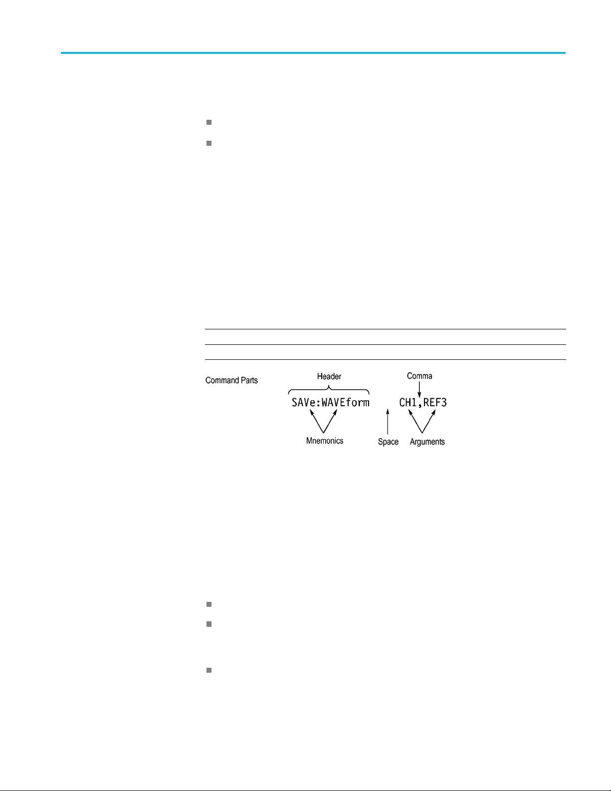
Messages
3 Series MDO Oscilloscopes Programmer Manual 2-1
A command message is a command or query name followed by any information
the oscilloscope n eeds to execute the command or query. Command messages
may contain five element type s, defined in the following table.

Command Syntax
Commands
Table 2-2: Comm
Symbol Meaning
<Header>
<Mnemonic>
<Argument
<Comma> A single c
<Space>
Comman
>
ds cause the oscilloscope to perform a specific function or change one of
and Message Elements
This is the basic command name. If the header ends with a question
mark, the command is a query. The header may begin with a colon
(:) c haracte
the beginning colon is required. Never use the beginning colon with
command headers beginning with a star (*).
This is a header subfunction. Some command headers have only one
mnemonic. I
character always separates them from each other.
This is a qu
Some commands have no arguments while others have multiple
arguments. A <space> separates arguments from the header. A
<comma> se
commands. Optionally, there may be white space characters before
and after the comma.
A white space character is used between a command header and the
related argument. O ptionally, a white space may consist of multiple
white sp
r. If the c ommand is concatenated with other commands,
f a command header has multiple mnemonics, a colon (:)
antity, quality, restriction, or limit associated with the header.
parates arguments from each other.
omma is used between arguments of multiple-argument
ace c haracters.
the settings. Commands have the structure:
eader>[<Space><Argument>[<Comma> <Argument>]...]
[:]<H
A command header consists of one or more mnemonics arranged in a hierarchical
ee structure. The first mnemonic is the base or root of the tree and each
or tr
subsequent mnemonic is a level or branch off the previous one. Commands at a
higher level in the tree may affect those at a lower level. The leading colon (:)
always returns you to the base of the command tree.
2-2 3 Series MDO Oscilloscopes Programmer Manual
Command Syntax
Queries
Headers
Queries cause t
have the structure:
[:]<Header>
[:]<Header>[<Space><Argument> [<Comma><Argument>]...]
You can specify a query command at any level within the command tree unless
otherwise noted. These branch queries return information about all the mnemonics
below the specified branch or level.
Use the HEADer command to control whether the oscilloscope returns headers as
part of the query response. If header is on, the query response returns command
headers, then formats itself as a valid set command. When header is off, the
response includes only the values. This may make it easier to parse and extract the
information from the response. The table below shows the difference in responses.
Table 2-3: Comparison of Header Off and Header On Responses
Query Header Off Header On
TIME?
ACQuire:NUMAVg?
he oscilloscope to return status or setting information. Queries
14:30:00 :TIME “14:30:00”
100
:ACQUIRE:NUMAVG 100
Clearing the oscilloscope
You can clear the Output Queue and reset the oscilloscope to accept a new
command or query by using the selected Device Clear (DCL) function.
Command Entry
The following rules apply when entering commands:
You can enter commands in upper or lower case.
You can precede any command with white space characters. White space
characters include any combination of the ASCII control characters 00 through
09 and 0B through 20 hexadecimal (0 through 9 and 11 through 32 decimal).
The oscilloscope ignores commands consisting of any combination of white
space characters and line feeds.
3 Series MDO Oscilloscopes Programmer Manual 2-3

Command Syntax
Abbreviating
Concatenating
You can abbrevi
ate many oscilloscope commands. Each command in this
documentation shows the minimum acceptable abbreviations in capitals. For
example, you can enter the command
ACQuire:NUMAvg simply as ACQ:NUMA
or acq:numa.
Abbreviation rules may change over time as new oscilloscope models are
introduced. Thus, for the most robust code, use the full spelling.
If you use the HEADer command to have command headers included as part
of query responses, you can further control whether the returned headers are
abbreviated or are full-length with the
VERBose command.
You can concatenate any combination of set commands and queries using a
semicolon (;). The oscilloscope exe cutes concatenated commands in the order
received.
When concatenating commands and queries, you must follow these rules:
1. Separate completely different headers by a semicolon and by the beginning
colon on all commands except the first one. For example, the commands
TRIGger:MODe NORMal and ACQuire:NUMAVg 8, can be concatenated
into the following single command:
TRIGger:MODe NORMal;:ACQuire:NUMAVg 8
2. If concatenated commands have headers that differ by only the last mnemonic,
you can abbreviate the second command and eliminate the beginning colon.
For example, you can concatenate the commands
ACQuire:MODe ENVelope
and ACQuire:NUMAVg 8 into a single command:
ACQuire:MODe ENVelope; NUMAVg 8
The longer version works equally well:
ACQuire:MODe ENVelope;:ACQuire:NUMAVg 8
3. Never precede a star (*) command with a colon:
ACQuire:STATE 1;*OPC
Any commands that follow will be processed as if the star command was
not there so the commands,
ACQuire:MODe ENVel
ope;*OPC;NUMAVg 8
will set the acquisition mode to envelope and set the number of acquisitions
for averaging to 8.
4. When you concat enate queries, the responses to all the queries are
concatenated into a single response message. For example, if the display
graticule is set to Full and the display style is set to dotsonly, the concatenated
query
DISplay:GRAticule?;STYle:DOTsonly? will return the following.
If the header is on:
DISPLAY:GRATICULE FULL;:DISPLAY:STYLE:DOTSONLY 1
2-4 3 Series MDO Oscilloscopes Programmer Manual

Command Syntax
If the header is
FULL;1
off:
1. Set commands and queries may be concatenated in the same message. For
example,
ACQuire:MODe SAMple;NUMAVg?;STATE?
is a valid message that sets the acquisition mode to sample. The message then
queries the number of acquisitions for averaging and the acquisition state.
Concatenated commands and queries are executed in the order received.
Here are some invalid concatenations:
DISPlay:STYle:DOTsonly OFF;ACQuire:NUMAVg 8 (no colon before
ACQuire)
DISPlay:GRAticule FULL;:STYle:DOTSONLY OFF (extra colon before
STYle.
DISPlay:GRAticule FULL;:*TRG (colon before a star (*) command)
MATH:HORizontal:SCAle 1.0e-1;HORizontal:POSition 5.0el
(levels of the mnemonics are different; either remove the second use of
HORizontal: or place :MATH in front of HORizontal:POSition)
Terminating
This documentation uses <EOM> (End of Message) to represent a message
terminator.
Table 2-4: End of Message Terminator
Sym
<E
The end-of-message terminator must be the END message (EOI asserted
concurrently with the last data byte). The last data byte may be an ASCII line
feed (LF) character.
This oscilloscope does not support ASCII LF only message termination. The
oscilloscope always terminates outgoing messages with LF and EOI.
Constructed Mnemonics
Some header mnemonics specify one of a range of mnemonics. For example, a
channel mnemonic can be CH1, CH2, CH3, or CH4. You use these mnemonics
in the command just as you do any other mnemonic. For example, there is a
CH1:POSition command, and there is also a CH2:POSition command. In the
command descriptions, this list of choices is abbreviated as CH<x>.
bol
OM>
ning
Mea
Message terminator
3 Series MDO Oscilloscopes Programmer Manual 2-5

Command Syntax
Math Spe
Cursor Position
Mnemonics
cifier Mnemonics
When cursors ar
e displayed, commands may specify which cursor of the pair to
use.
Table 2-5: Channel Mnemonics
Symbol Meaning
CH<x> A channel specifier; <x> is 1 through 4.
Table 2-6: Cursor Mnemonics
Symbol Meaning
CURSOR<x>
POSITION<x>
HPOS<x>
A cursor selector; <x> is either 1 or 2.
A cursor selector; <x> is either 1 or 2.
A cursor selector; <x> is either 1 or 2.
Commands can specify the mathematical waveform to use as a mnemonic in
the header.
Table 2-7: Math Specifier Mnemonics
Symbol Meaning
Math<x>
A math waveform specifier; <x> is 1.
Measurement Specifier
Mnemonics
hannel Mnemonics
C
Reference Waveform
Mnemonics
Commands can specify which measurement to set or query as a mnemonic in the
header. Up to eight automated measurements may be displayed.
Table 2-8: Measurement Specifier Mnemonics
Symbol Meaning
MEAS<x> A measurement specifier; <x> is 1 through 8.
Commands specify the channel to use as a mnemonic in the header.
Commands can specify the reference waveform to use as a mnemonic in the
header.
Table 2-9: Reference Waveform Mnemonics
Symbol Meaning
REF<x>
A reference waveform specifier; <x> is 1, 2, 3, or 4 for 4-channel
oscilloscopes and 1 or 2 for 2-channel oscilloscopes.
2-6 3 Series MDO Oscilloscopes Programmer Manual

Argument Types
Command Syntax
Commands use arguments such as enumeration, numeric, quoted string and block.
Each of these arguments are listed in detail below.
Enumeration
Numeric
Enter these arguments as unquoted text words. Like key words, enumeration
arguments follow the same convention where the portion indicated in uppercase is
required and that in lowercase is optional.
For example:
Many osci
SAVe:WAVEform:FILEFormat INTERNal
lloscope commands require numeric arguments. The syntax shows
the format that the oscilloscope returns in response to a query. This is also the
preferred format when sending the command to the oscilloscope, though any of
the formats will be accepted. This documentation represents these arguments as
described below.
Table 2-10: Numeric Arguments
Symbol Meaning
<NR1>
<NR2> Floating point value without an exponent
<NR3> Floating point value with an exponent
<bin>
Signed integer value
Signed or unsigned integer in binary format
Most numeric arguments will be automatically forced to a valid setting, by either
rounding or truncating, when an invalid number is input, unless otherwise noted
the command description.
in
Quoted String
Some commands accept or return data in the form of a quoted string, which is
simply a group of ASCII characters enclosed by a single quote (') or double quote
"). The following is an example of a quoted string:
(
string"
. This documentation represents these arguments as follows:
"This is a quoted
Table 2-11: Quoted String Argument
Symbol Meaning
<QString> Quoted string of ASCII text
3 Series MDO Oscilloscopes Programmer Manual 2-7

Command Syntax
A quoted string
can include any character defined in the 7-bit ASCII character
set. Follow these rules when you use quoted strings:
1. Use the same ty
example:
2. You can mix q
previous rule. For example:
3. You c an i ncl
example:
4. Strings ca
pe of quote character to open and close the string. For
"this is a valid string".
uotation marks within a string as long as you follow the
"this is an 'acceptable' string".
ude a quote character within a string by repeating the quote. For
"here is a "" mark ".
n have u pper or lower case characters.
5. If you use a GPIB network, you cannot terminate a quoted string with the
END messa
ge before the closing delimiter.
6. A carriage return or line feed embedded in a quoted string does not terminate
ng. The return is treated as another c haracter in the string.
the stri
7. The maximum length of a quoted string returned from a query is 1000
ters.
charac
Here are some invalid strings:
"Invalid string argument' (quotes are not of the same type)
Block
"test<EOI>" (termination character is embedded in the string)
Several oscilloscope commands use a block argument form, as defined in the
table below.
Table 2-12: Block Argument
Symbol Meaning
<NZDig>
<Dig>
<DChar> A character with the hexadecimal equivalent of 00 through FF (0
<Block>
A nonzero digit character in the range of 1–9
A digit character, in the range of 0–9
through 255 decimal)
A block of data bytes defined as: <Block> ::=
{#<NZDig><Dig>[<Dig>...][<DChar>...] |#0[<D Char>...]<term inator>}
<NZDig> specifies the number of <Dig> elements that follow. Taken together,
the <NZDig> and <Dig> elements form a decimal integer that specifies how
many <DChar> elements follow.
2-8 3 Series MDO Oscilloscopes Programmer Manual
 Loading...