


3 Series Mixed Domain Oscilloscope
Printable Help
(MDO32, MDO34)
arning: The servicing instructions are for use by qualified personnel only. To avoid personal injury, do not perform any servicing unless you are qualified
W
to do so. Refer to all safety summaries prior to performing service.
Supports Product Firmware V1.10.0 and later
Register now!
Click the following link to protect your product.
www.tek.com/register
*P 077149702*
077-1497-02

Copyright © Tektronix. All rights reserved. Licensed software products are owned by Tektronix or its subsidiaries or suppliers, and are
protected by national copyright laws and international treaty provisions. T
and pending. Information in this publication supersedes that in all previously published material. Specifications and price change privileges
reserved.
TEKTRONIX and TEK are registered trademarks of Tektronix, Inc.
This product contains open source software. License information is available at (your instrument IP address)/opensource. To find your
instrument IP address tap Utility > I/O. For programs licensed under the "GNU General Public License (GPL) or Lesser GNU General
Public License (LGPL)" the complete corresponding sources are available. You can order a CD containing the sources from us for a period
of three years after download of the software, by sending a written request to:
Chief Intellectual Property Counsel, Tektronix, Inc.
MS 50/LAW
14150 SW Karl Braun Dr.
Beaverton OR, 97077
This offer is valid to anyone in receipt of this information.
Your request should include: (i) the name of the product, (ii) your (company) name, and (iii) your return mailing and email address (if
available).
Please note that we may charge you a fee to cover the cost of performing this distribution.
Contacting Tektronix
Tektronix, Inc.
ektronix products are covered by U.S. and foreign patents, issued
14150 SW Karl Braun Drive
P.O. Box 500
Beaverton, OR 97077
USA
For product information, sales, service, and technical support:
• In North America, call 1-800-833-9200.
• Worldwide, visit www.tek.com to find contacts in your area.

Table of Contents
Table of Contents
List of Figures..............................................................................................................................................................................10
List of Tables................................................................................................................................................................................11
TEKTRONIX END USER LICENSE AGREEMENT....................................................................................................................12
Open Source GPL License Notice.............................................................................................................................................. 16
GPU disclosure........................................................................................................................................................................... 17
Welcome to the 3 Series MDO instrument help ......................................................................................................................... 19
Product documents and support................................................................................................................................................. 20
Related documents.............................................................................................................................................................. 20
Product support and feedback............................................................................................................................................. 20
Accessories.................................................................................................................................................................................22
Standard accessories.......................................................................................................................................................... 22
Recommended accessories.................................................................................................................................................22
Recommended probes.........................................................................................................................................................23
Factory options............................................................................................................................................................................25
Bandwidth options................................................................................................................................................................25
Digital channels option.........................................................................................................................................................25
Spectrum analyzer frequency range options....................................................................................................................... 25
Arbitrary Function Generator (AFG) option..........................................................................................................................25
Enhanced instrument security..............................................................................................................................................26
Serial bus decode and trigger options................................................................................................................................. 26
Power Analysis option..........................................................................................................................................................26
Application bundle................................................................................................................................................................27
Power cord options.............................................................................................................................................................. 27
Service options.................................................................................................................................................................... 27
Option upgrades..........................................................................................................................................................................29
Post-purchase instrument options....................................................................................................................................... 29
Bandwidth upgrade options................................................................................................................................................. 29
How to install an option license............................................................................................................................................30
Install your instrument................................................................................................................................................................. 32
Check shipped accessories................................................................................................................................................. 32
Safely rotate the handle....................................................................................................................................................... 32
Operating requirements....................................................................................................................................................... 33
Input signal requirements.....................................................................................................................................................33
Powering the oscilloscope................................................................................................................................................... 34
Check that the oscilloscope passes power-on self tests......................................................................................................35
Secure (lock) the oscilloscope............................................................................................................................................. 35
Connecting probes...............................................................................................................................................................36
Rackmount information........................................................................................................................................................ 37
Getting acquainted with your instrument.....................................................................................................................................38
Front panel controls and connectors....................................................................................................................................38
Rear panel connections....................................................................................................................................................... 43
The user interface screen.................................................................................................................................................... 44
Identifying items in the time domain display........................................................................................................................ 45
Identifying items in the frequency domain display............................................................................................................... 47
3 Series Mixed Domain Oscilloscope Printable Help 3

Table of Contents
Identifying items in the arbitrary function generator display.................................................................................................49
Identifying items in the digital voltmeter display
...................................................................................................................49
Badges.................................................................................................................................................................................50
Configuration menus............................................................................................................................................................54
Zoom user interface elements............................................................................................................................................. 55
Using the touchscreen interface for common tasks............................................................................................................. 55
Accessing application help...................................................................................................................................................57
Configure the instrument.............................................................................................................................................................58
Set the date and time...........................................................................................................................................................58
Functional check.................................................................................................................................................................. 58
Download and install the latest firmware............................................................................................................................. 59
Run Signal Path Compensation (SPC)................................................................................................................................ 59
Compensate TPP0250, TPP0500B, or TPP1000 probes.................................................................................................... 60
Compensate passive probes............................................................................................................................................... 61
Connect to a network (LAN).................................................................................................................................................62
Mount a network drive..........................................................................................................................................................62
Unmount a network drive..................................................................................................................................................... 63
Deskew analog input channels - quick visual method......................................................................................................... 63
Deskew analog input channels - measurement method...................................................................................................... 64
Connect a keyboard or mouse.............................................................................................................................................64
Connect an external monitor or projector.............................................................................................................................65
ESD prevention guidelines...................................................................................................................................................65
Analog channel operating basics................................................................................................................................................ 66
Acquiring a signal.................................................................................................................................................................66
Quickly display a waveform (autoset).................................................................................................................................. 66
Set horizontal parameters....................................................................................................................................................67
How to trigger on a signal.................................................................................................................................................... 67
Set the acquisition mode......................................................................................................................................................68
Start and stop an acquisition................................................................................................................................................69
Add a channel waveform to the display............................................................................................................................... 69
Configure channel or waveform settings..............................................................................................................................70
Add a math, reference, or bus waveform.............................................................................................................................71
Add a measurement.............................................................................................................................................................72
Configure a measurement................................................................................................................................................... 74
Delete a measurement or search badge..............................................................................................................................75
Display an XY waveform......................................................................................................................................................75
Display an FFT math waveform........................................................................................................................................... 76
Add a search........................................................................................................................................................................76
Change waveform view settings.......................................................................................................................................... 77
Display and configure cursors..............................................................................................................................................78
Using Default Setup............................................................................................................................................................. 78
Using Fast Acq.....................................................................................................................................................................79
Remote access from a Web browser...................................................................................................................................80
Connect the oscilloscope to a PC using a USB cable......................................................................................................... 80
Acquiring digital signals...............................................................................................................................................................81
Acquiring digital signals....................................................................................................................................................... 81
Connect and set up digital signals....................................................................................................................................... 81
Add a serial bus to the Waveform view................................................................................................................................82
Add a parallel bus to the Waveform view.............................................................................................................................84
3 Series Mixed Domain Oscilloscope Printable Help 4

Table of Contents
Advanced triggering.................................................................................................................................................................... 87
Advanced triggering
............................................................................................................................................................. 87
Triggering concepts..............................................................................................................................................................87
Trigger on a pulse width event.............................................................................................................................................87
Set Trigger Holdoff...............................................................................................................................................................88
Trigger on sequential events (A and B triggers)...................................................................................................................89
Set up trigger on a parallel bus............................................................................................................................................ 89
Set up trigger on a serial bus............................................................................................................................................... 90
Trigger using the AUX input.................................................................................................................................................90
Setting waveform display parameters......................................................................................................................................... 91
Setting waveform display parameters..................................................................................................................................91
Set the waveform persistence style and intensity................................................................................................................ 91
Set the graticule style and intensity..................................................................................................................................... 91
Zooming on waveforms...............................................................................................................................................................92
Zooming on waveforms........................................................................................................................................................92
Turn on Zoom mode.............................................................................................................................................................92
Zoom mode and Searches...................................................................................................................................................92
Customizing measurements........................................................................................................................................................94
Customizing measurements................................................................................................................................................ 94
Set measurement reference levels...................................................................................................................................... 94
Set measurement gates.......................................................................................................................................................94
Saving and recalling information................................................................................................................................................. 96
Save a screen image........................................................................................................................................................... 97
Save a waveform to a file.....................................................................................................................................................97
Save instrument settings to a file......................................................................................................................................... 98
Save all................................................................................................................................................................................ 98
Recall a Reference waveform..............................................................................................................................................99
Recall a Setup file................................................................................................................................................................ 99
Menus and dialog boxes........................................................................................................................................................... 100
The Acquisition configuration menu...................................................................................................................................100
Add Measurements configuration menu overview............................................................................................................. 101
Amplitude Measurements panel................................................................................................................................. 102
Time Measurements panel......................................................................................................................................... 104
Other Measurements panel........................................................................................................................................ 105
The Power Measurements panel (optional)................................................................................................................106
Measurement configuration menu...................................................................................................................................... 111
Measurement Name panel (Measurement configuration menu)................................................................................. 111
Global Measurement Settings panel (Measurement configuration menu).................................................................. 112
Power measurement configuration menu overview (optional)........................................................................................... 114
Power Measurement Name panel (Measurement configuration menu)......................................................................114
SOA Mask definition controls and fields......................................................................................................................115
Reference Levels panel (Power measurement configuration Menu).......................................................................... 115
Bus configuration menu......................................................................................................................................................115
ARINC429 serial bus menu.........................................................................................................................................117
Audio serial bus configuration menu...........................................................................................................................118
CAN serial bus configuration menu............................................................................................................................ 120
FlexRay serial bus configuration menu.......................................................................................................................122
I2C serial bus configuration menu.............................................................................................................................. 123
LIN serial bus configuration menu.............................................................................................................................. 124
3 Series Mixed Domain Oscilloscope Printable Help 5

Table of Contents
MIL-STD-1553 serial bus menu..................................................................................................................................126
Parallel Bus configuration menu
................................................................................................................................. 127
Parallel Bus - Define Inputs menu.............................................................................................................................. 129
RS-232 serial bus menu............................................................................................................................................. 129
SPI serial bus configuration menu.............................................................................................................................. 131
USB serial bus configuration menu.............................................................................................................................132
Add Results Table.............................................................................................................................................................. 134
Search configuration menu overview.................................................................................................................................135
Bus Search configuration menus................................................................................................................................135
ARINC429 serial bus search configuration menu.......................................................................................................136
Audio serial bus search configuration menu...............................................................................................................138
CAN serial bus search configuration menu.................................................................................................................139
FlexRay serial bus search configuration menu...........................................................................................................141
I2C serial bus search configuration menu...................................................................................................................143
LIN serial bus search configuration menu...................................................................................................................144
MIL-STD-1553 Search configuration menu................................................................................................................ 146
Parallel bus search configuration menu......................................................................................................................148
RS-232 serial bus search configuration menu............................................................................................................149
SPI serial bus search configuration menu.................................................................................................................. 149
USB serial bus search configuration menu.................................................................................................................150
Edge Search configuration menu................................................................................................................................152
Logic Search configuration menu............................................................................................................................... 153
Logic Search - Define Inputs configuration menu.......................................................................................................155
Pulse Width Search configuration menu.....................................................................................................................155
Rise/Fall Time Search configuration menu.................................................................................................................156
Runt Search configuration menu................................................................................................................................ 158
Setup and Hold Search configuration menu............................................................................................................... 159
Setup and Hold Search - Define Inputs configuration menu.......................................................................................160
Timeout Search configuration menu...........................................................................................................................160
Analog Channel configuration menu..................................................................................................................................161
Probe Setup panel (Channel configuration menu)......................................................................................................163
Probe Compensation configuration menu (analog channels Probe Setup panel)...................................................... 163
Other panel (Channel configuration menu).................................................................................................................164
Deskew configuration menu (Other panel Channel configuration menu)................................................................... 164
AFG configuration menu.................................................................................................................................................... 165
Save As configuration menu (AFG menu)......................................................................................................................... 168
RF configuration menu.......................................................................................................................................................169
Traces panel (RF configuration menu)....................................................................................................................... 169
Horizontal badge configuration menu................................................................................................................................ 170
Spectral math configuration menu..................................................................................................................................... 171
Spectral Ref configuration menu........................................................................................................................................171
Cursor configuration menu.................................................................................................................................................172
Date and Time configuration menu....................................................................................................................................173
Digital channel configuration menu....................................................................................................................................173
DVM configuration menu................................................................................................................................................... 174
Menu bar overview.............................................................................................................................................................175
Recall configuration menu (File menu)....................................................................................................................... 176
Save As configuration menu (File menu)....................................................................................................................177
Print configuration menu.............................................................................................................................................180
3 Series Mixed Domain Oscilloscope Printable Help 6

Table of Contents
Add Printer configuration menu.................................................................................................................................. 180
File Utilities configuration (File menu)
.........................................................................................................................181
Mount Network Drive configuration menu...................................................................................................................182
User Preferences (Utility menu)..................................................................................................................................183
I/O (Utility menu).........................................................................................................................................................184
LAN Reset configuration menu (Utility > I O menu)....................................................................................................186
Self Test configuration menu (Utility menu)................................................................................................................ 187
Calibration configuration menu (Utility menu).............................................................................................................188
Security configuration menu (Utility menu)................................................................................................................. 188
Enter Password configuration menu (optional)...........................................................................................................189
Set Password configuration menu (optional).............................................................................................................. 190
Demo (Utility menu).................................................................................................................................................... 191
Help (Help menu)........................................................................................................................................................191
About (Help menu)......................................................................................................................................................191
Horizontal configuration menu........................................................................................................................................... 192
Math configuration menu overview.................................................................................................................................... 192
Math configuration menu............................................................................................................................................ 193
Equation Editor (Math configuration menu)................................................................................................................ 195
Add Functions (math Equation Editor)........................................................................................................................195
Pick Measurement...................................................................................................................................................... 196
Reference waveform configuration menu.......................................................................................................................... 196
Recall configuration menu (Ref waveform configuration menu)........................................................................................ 197
Search configuration menu................................................................................................................................................ 198
Trigger configuration menu overview.................................................................................................................................198
Bus Trigger configuration............................................................................................................................................199
ARINC429 serial bus trigger settings panel................................................................................................................200
Audio serial bus trigger settings panel........................................................................................................................201
CAN serial bus trigger settings panel..........................................................................................................................202
FlexRay serial bus trigger settings panel....................................................................................................................204
I2C serial bus trigger settings panel............................................................................................................................206
LIN serial bus trigger settings panel............................................................................................................................207
MIL-STD-1553 serial bus trigger settings panel..........................................................................................................209
Parallel serial bus trigger settings panel..................................................................................................................... 211
RS-232 serial bus trigger settings panel..................................................................................................................... 211
SPI serial bus trigger settings panel........................................................................................................................... 212
USB serial bus trigger settings panel..........................................................................................................................213
Edge Trigger configuration menu................................................................................................................................215
Logic Trigger configuration menu............................................................................................................................... 216
Logic Trigger - Define Inputs configuration menu.......................................................................................................218
Pulse Width Trigger configuration menu.....................................................................................................................218
Rise Fall Time Trigger configuration menu.................................................................................................................219
Runt Trigger configuration menu................................................................................................................................ 220
Sequence Trigger configuration menu........................................................................................................................222
Setup & Hold Trigger configuration menu...................................................................................................................223
Setup & Hold Trigger - Define Inputs configuration menu.......................................................................................... 224
Timeout Trigger configuration menu...........................................................................................................................224
Video trigger configuration menu................................................................................................................................225
Mode and Holdoff panel..............................................................................................................................................226
Act On Trigger configuration menu.............................................................................................................................227
3 Series Mixed Domain Oscilloscope Printable Help 7

Table of Contents
Viewing the trigger frequency..................................................................................................................................... 228
V
irtual Keyboard.................................................................................................................................................................228
Binary, decimal, hex, and octal virtual keypads................................................................................................................. 228
Numeric input keypad........................................................................................................................................................ 229
IP address keypad............................................................................................................................................................. 229
Waveform View configuration menu.................................................................................................................................. 230
Cursors menu (RF view) ................................................................................................................................................... 232
RF badge menu................................................................................................................................................................. 233
Waveform acquisition concepts.................................................................................................................................................235
Acquisition concepts.......................................................................................................................................................... 235
Acquisition hardware...................................................................................................................................................235
Sampling process....................................................................................................................................................... 235
Waveform record........................................................................................................................................................ 235
Acquisition modes..............................................................................................................................................................236
How the acquisition modes work................................................................................................................................ 236
Coupling.............................................................................................................................................................................237
Scaling and positioning...................................................................................................................................................... 237
Vertical acquisition considerations.....................................................................................................................................237
Horizontal acquisition considerations.................................................................................................................................238
Using reference waveforms and traces............................................................................................................................. 238
Frequency-Domain concepts............................................................................................................................................. 239
Displaying the Frequency Domain menu....................................................................................................................239
RF waveform view and badges...................................................................................................................................239
Spectrum trace handle................................................................................................................................................240
Spectrum trace markers..............................................................................................................................................241
The RF waveform view user interface........................................................................................................................ 241
Using spectral analysis controls..................................................................................................................................242
Setting up the RF input............................................................................................................................................... 242
Resolution bandwidth................................................................................................................................................. 243
Spectrogram display................................................................................................................................................... 244
Automatic peak markers............................................................................................................................................. 245
Frequency domain cursors......................................................................................................................................... 245
Use the Arbitrary Function Generator................................................................................................................................ 246
Triggering concepts...................................................................................................................................................................250
Trigger sources.................................................................................................................................................................. 250
Trigger types...................................................................................................................................................................... 250
Trigger modes....................................................................................................................................................................251
Trigger holdoff....................................................................................................................................................................251
Trigger coupling................................................................................................................................................................. 252
Trigger slope and level.......................................................................................................................................................252
Trigger position in waveform record...................................................................................................................................252
Trigger delay...................................................................................................................................................................... 252
Bus triggering concepts..................................................................................................................................................... 252
Pulse width trigger concepts.............................................................................................................................................. 253
Timeout trigger...................................................................................................................................................................253
Runt trigger........................................................................................................................................................................ 253
Logic trigger concepts........................................................................................................................................................253
Setup and Hold trigger concepts........................................................................................................................................253
Rise/Fall time trigger concepts...........................................................................................................................................254
3 Series Mixed Domain Oscilloscope Printable Help 8

Table of Contents
Sequential (A B) trigger concepts...................................................................................................................................... 254
W
aveform display concepts...................................................................................................................................................... 255
Waveform display overview............................................................................................................................................... 255
Waveform preview mode................................................................................................................................................... 255
Horizontal position and the horizontal reference point.......................................................................................................255
Annotating the screen........................................................................................................................................................ 255
Vertical graticule readout................................................................................................................................................... 256
Measurement concepts.............................................................................................................................................................257
Taking automatic measurements in the time domain......................................................................................................... 257
Taking automatic measurements in the frequency domain................................................................................................ 257
Taking digital voltmeter measurements..............................................................................................................................257
Taking manual measurements with cursors....................................................................................................................... 258
Making automated power measurements..........................................................................................................................259
Using cursor readouts........................................................................................................................................................260
Using XY Cursors.............................................................................................................................................................. 260
Measurement variables......................................................................................................................................................260
Missing or out-of-range samples........................................................................................................................................262
Math waveforms.................................................................................................................................................................262
Math waveform elements...................................................................................................................................................262
Guidelines for working with math waveforms.....................................................................................................................263
Math waveform editor syntax............................................................................................................................................. 263
Math waveform differentiation............................................................................................................................................264
Math waveform offset position and scale...........................................................................................................................264
Waveform integration.........................................................................................................................................................264
Using math waveforms...................................................................................................................................................... 265
Using advanced math........................................................................................................................................................ 266
Using FFT.......................................................................................................................................................................... 266
FFT process.......................................................................................................................................................................267
FFT and aliasing................................................................................................................................................................ 267
Blackman-Harris FFT window concepts.............................................................................................................................268
Hanning FFT window......................................................................................................................................................... 268
Hamming window...............................................................................................................................................................269
Rectangular window...........................................................................................................................................................269
Using spectrum math......................................................................................................................................................... 269
References................................................................................................................................................................................271
Upgrading firmware............................................................................................................................................................271
Cleaning.............................................................................................................................................................................271
Index......................................................................................................................................................................................... 272
3 Series Mixed Domain Oscilloscope Printable Help 9

List of Figures
List of Figures
Figure 1: Power cord connector and power standby switch........................................................................................................35
Figure 2: Connecting probes to the instrument........................................................................................................................... 36
Figure 3: 3 Series MDO controls.................................................................................................................................................38
Figure 4: Probe Comp connections.............................................................................................................................................61
Figure 5: Spectrum trace MANm handle info............................................................................................................................ 240
Figure 6: Spectrum trace markers.............................................................................................................................................241
Figure 7: Lower (narrower) RBWs take longer to process, but have finer frequency resolution and a lower noise floor. ........244
Figure 8: Higher (wider) RBWs take less time to process, but have less frequency resolution and a higher noise floor. ........244
Figure 9: The channel 1 sine wave shows the output of the AFG. The channel 2 square wave show the output of the
AFG sync pulse. It comes from the AUX OUT port.....................................................................................................248
3 Series Mixed Domain Oscilloscope Printable Help 10

List of Tables
List of Tables
Table 1: 3 Series bandwidth options........................................................................................................................................... 25
Table 2: 3 Series MSO option..................................................................................................................................................... 25
Table 3: 3 Series spectrum analyzer options.............................................................................................................................. 25
Table 4: 3 Series AFG option...................................................................................................................................................... 26
Table 5: Enhanced instrument security pre-installed option........................................................................................................ 26
Table 6: 3 Series serial bus options............................................................................................................................................ 26
Table 7: 3 Series power option.................................................................................................................................................... 26
Table 8: 3 Series bundle option................................................................................................................................................... 27
Table 9: Instrument upgrade options........................................................................................................................................... 29
Table 10: MDO32 bandwidth upgrades....................................................................................................................................... 30
Table 11: MDO34 bandwidth upgrades....................................................................................................................................... 30
Table 12: Maximum analog input................................................................................................................................................ 33
Table 13: Maximum input with a P6316 Digital Probe................................................................................................................. 34
Table 14: Common touchscreen UI tasks (with mouse equivalents)...........................................................................................55
Table 15: Security configuration menu fields and controls........................................................................................................ 189
3 Series Mixed Domain Oscilloscope Printable Help 11

TEKTRONIX END USER LICENSE AGREEMENT
TEKTRONIX END USER LICENSE AGREEMENT
This End User Agreement (“Agreement”) is an agreement between Tektronix, Inc., an Oregon corporation, and its corporate affiliates,
subsidiaries, and divisions as applicable (collectively, “Tektronix,” “we,” “us,” or “our”) and You (including any entity or organization you
represent, collectively, “Customer” or “You”). Please read this Agreement carefully as this Agreement governs the terms and conditions
under which You are permitted to use Tektronix’s software and services.
THE SOFTWARE, ENCODED OR INCORPORATED WITHIN EQUIPMENT OR ACCOMPANYING THIS AGREEMENT, IS FURNISHED
SUBJECT TO THE TERMS AND CONDITIONS OF THIS AGREEMENT. BY INDICATING YOUR ACCEPTANCE OF THESE TERMS
BY SELECTING AN "ACCEPT” OR SIMILAR BUTTON IN A SOFTWARE MENU, OR BY RETAINING THE SOFTWARE FOR MORE
THAN THIRTY DAYS OR USING THE SOFTWARE IN ANY MANNER YOU (A) ACCEPT THIS AGREEMENT AND AGREE THAT YOU
ARE LEGALLY BOUND BY ITS TERMS; AND (B) REPRESENT AND WARRANT THAT: (I) YOU ARE OF LEGAL AGE TO ENTER
INTO A BINDING AGREEMENT; AND (II) IF YOU ARE A REPRESENTATIVE FOR A CORPORATION OR OTHER LEGAL ENTITY,
YOU HAVE THE RIGHT, POWER, AND AUTHORITY TO ENTER INTO THIS AGREEMENT ON BEHALF OF SUCH ENTITY AND BIND
SUCH ENTITY TO ITS TERMS. IF YOU DO NOT AGREE TO THE TERMS OF THIS AGREEMENT, TEKTRONIX WILL NOT AND DOES
NOT LICENSE THE SOFTWARE TO YOU AND YOU MUST NOT DOWNLOAD, INSTALL, OR USE THE SOFTWARE. UNITED STATES
GOVERNMENT CUSTOMERS OR END-USERS MAY REQUEST A GOVERNMENT ADDENDUM TO THIS AGREEMENT.
NOTWITHSTANDING ANYTHING TO THE CONTRARY IN THIS AGREEMENT OR YOUR ACCEPTANCE OF THE TERMS AND
CONDITIONS OF THIS AGREEMENT, NO LICENSE IS GRANTED (WHETHER EXPRESSLY, BY IMPLICATION, OR OTHERWISE)
UNDER THIS AGREEMENT TO ANY SOFTWARE THAT YOU DID NOT ACQUIRE LAWFULLY OR THAT IS NOT A LEGITIMATE,
AUTHORIZED COPY OF TEKTRONIX’S SOFTWARE. THIS AGREEMENT EXPRESSLY EXCLUDES ANY RIGHTS CONCERNING
SUCH ILLEGITIMATE COPIES.
IF THESE TERMS ARE NOT ACCEPTABLE, THE UNUSED SOFTWARE AND ANY ACCOMPANYING DOCUMENTATION SHOULD BE
RETURNED PROMPTLY TO TEKTRONIX (WITHIN 30 DAYS OF PURCHASE) FOR A FULL REFUND OF THE LICENSE FEE PAID.
(FOR INFORMATION REGARDING THE RETURN OF SOFTWARE ENCODED OR INCORPORATED WITHIN EQUIPMENT, CONTACT
THE NEAREST TEKTRONIX SALES OFFICE.)
DEFINITIONS.
“Equipment” means Tektronix equipment that the Software is encoded or incorporated within or installed onto.
LICENSE.
Subject to the terms and conditions of this Agreement, Tektronix grants You a non-exclusive, non-transferable license to the Software, as
follows.
You may:
1. Use the Software with the Equipment, or if the Software is not encoded or incorporated in any Tektronix equipment, on no more than
one machine at a time; and
2. Copy the Software for archival or backup purposes, provided that no more than one (1) such copy is permitted to exist at any one time,
and provided that each copy includes a reproduction of any patent or copyright notice or restrictive rights legend that was included with
the Software, as received from Tektronix;
3. Fully transfer the Equipment to a third party but only if prominently accompanied by this End User License Agreement, and such
third-party recipients agree to be bound by the terms of this Agreement; and
4. Integrate Tektronix products that contain the Software into a system and sell or distribute that system to third parties, provided that
those third parties are bound by the terms of this Agreement, and provided that You (i) do not separate the Software from any
Equipment it is incorporated into, (ii) do not retain any copies of the Software, and (iii) do not modify the Software.
You may not:
1. Use the Software other than for its intended purpose as provided above in the section “You may,” or in conflict with the terms and
restrictions of this Agreement;
2. Distribute or transfer the Software to any person or organization outside of Your organization without Tektronix’s prior written consent,
except in connection with a permitted use authorized in “You may” paragraphs 3 or 4 above;
3 Series Mixed Domain Oscilloscope Printable Help 12

TEKTRONIX END USER LICENSE AGREEMENT
3. Decompile, decrypt, disassemble, or otherwise attempt to derive the source code, techniques, processes, algorithms, know-how
or other information (collectively “Reverse Engineer”) from the Software or permit or induce any third party to do so, except to the
limited extent allowed by directly applicable law or third party license (if any), and only to obtain information necessary to achieve
interoperability of independently created software with the Software;
4. Modify, translate, adapt, or create derivative works of the Software, or merge the Software with any other software;
5. Copy the documentation accompanying the Software;
6. Remove any copyright, trademark, or other proprietary notices from the Software or any media relating thereto; or
7. Export or re-export, directly or indirectly, the Software or Equipment, any associated documentation, or systems created in
accordance with “You may” section 4 above, to any country to which such export or re-export is restricted by law or regulation of
the United States or any foreign government having jurisdiction without the prior authorization, if required, of the Office of Export
Administration, Department of Commerce, Washington, D.C. and the corresponding agency of such foreign government;
8. Use the Software or Equipment in any manner or for any purpose that infringes, misappropriates, or otherwise violates any
intellectual property rights or other proprietary rights of any person, or any applicable laws;
9. Use the Software or Equipment in a network or system with other products or services that are incompatible, insecure or not
compliant with applicable laws;
10. Bypass, circumvent, damage or otherwise interfere with any security or other features of the Software or Equipment designed to
control the manner in which they are used, or harvest or mine Tektronix’s proprietary content or information from the Software or
Equipment.
THE SOFTWARE MAY NOT BE USED, COPIED, MODIFIED, MERGED, OR TRANSFERRED TO ANOTHER EXCEPT AS EXPRESSLY
PERMITTED BY THESE TERMS AND CONDITIONS.
FEEDBACK
If You provide feedback to Tektronix concerning the functionality and performance of the Software or Equipment, including without limitation
identifying potential errors and improvements, any comments, questions, suggestions, or the like ("Feedback"), Tektronix is free to use
such Feedback without any attribution, compensation, or restriction in any manner to improve or enhance its products, irrespective of
any other obligation or limitation between the Parties governing such Feedback. You hereby grant Tektronix an irrevocable, worldwide,
perpetual, royalty-free license to use Your Feedback for any purpose whatsoever and waive any moral rights You may have in the
Feedback. Tektronix is not obligated to use Your Feedback.
,
OWNERSHIP
Title to the Software and all copies thereof, but not the media on which the Software or copies may reside, shall remain with Tektronix or
others from whom Tektronix has obtained a respective licensing right.
GOVERNMENT NOTICE
If the Software or any related documentation is acquired by or for an agency of the U.S. Government, the Software and documentation
shall be considered “commercial computer software” or “commercial computer software documentation” respectively, as those terms are
used in 48 CFR §12.212, 48 CFR §227.7202, or 48 CFR §252.227-7014, and are licensed with only those rights as are granted to all other
licensees as set forth in this Agreement.
TERM
The license granted herein is effective until terminated. The license may be terminated by You at any time upon written notice to Tektronix.
The license may be terminated by Tektronix if You fail to comply with any term or condition and such failure is not remedied within fifteen
(15) days after notice hereof from Tektronix. Upon termination by either party, You shall return to Tektronix or destroy, the Software and all
associated documentation, together with all copies in any form.
IF YOU TRANSFER, DISTRIBUTE, OR OTHERWISE MAKE AVAILABLE ANY COPY, MODIFICATION, OR MERGED PORTION OF THE
SOFTWARE WITHOUT THE AS EXPRESS PERMISSION OF THESE TERMS AND CONDITIONS OR PRIOR WRITTEN CONSENT OF
TEKTRONIX, YOUR LICENSE WILL BE IMMEDIATELY AND AUTOMATICALLY TERMINATED.
LIMITED WARRANTY.
Tektronix does not warrant that the functions contained in the Software will meet Your requirements or that the operation of the Software
will be uninterrupted, secure, or error-free.
3 Series Mixed Domain Oscilloscope Printable Help 13

TEKTRONIX END USER LICENSE AGREEMENT
EXCEPT AS SEPARATELY PROVIDED IN A WRITTEN WARRANTY FROM TEKTRONIX, THE SOFTWARE IS PROVIDED “AS IS”
WITHOUT ANY W
MERCHANTABILITY, FITNESS FOR A PARTICULAR PURPOSE, TITLE, QUIET ENJOYMENT, AND NON-INFRINGEMENT.
THE SOFTWARE IS NOT DESIGNED OR INTENDED FOR USE IN HAZARDOUS ENVIRONMENTS REQUIRING FAIL-SAFE
PERFORMANCE INCLUDING WITHOUT LIMITATION, IN THE OPERATION OF NUCLEAR FACILITIES, AIRCRAFT NAVIGATION
OR COMMUNICATION SYSTEMS, AIR TRAFFIC CONTROL, WEAPONS SYSTEMS, DIRECT LIFE-SUPPORT MACHINES, OR ANY
OTHER APPLICATION IN WHICH THE FAILURE OF THE SOFTWARE COULD LEAD TO DEATH, PERSONAL INJURY OR SEVERE
PHYSICAL OR PROPERTY DAMAGE (COLLECTIVELY "HAZARDOUS ACTIVITIES"). TEKTRONIX AND ITS AFFILIATES, LICENSORS,
AND RESELLERS EXPRESSLY DISCLAIM ANY EXPRESS OR IMPLIED WARRANTY OF FITNESS FOR HAZARDOUS ACTIVITIES.
LIMITATION OF LIABILITY
IN NO EVENT SHALL TEKTRONIX, ITS AFFILIATES, LICENSORS, OR RESELLERS BE LIABLE FOR: (1) ECONOMICAL,
INCIDENTAL, CONSEQUENTIAL, INDIRECT, SPECIAL, PUNITIVE OR EXEMPLARY DAMAGES, WHETHER CLAIMED UNDER
CONTRACT, TORT OR ANY OTHER LEGAL THEORY, (2) LOSS OF OR DAMAGE TO YOUR DATA OR PROGRAMMING, LOSS
OF PROFITS, BUSINESS INTERRUPTION, OR OTHER PECUNIARY LOSS ARISING FROM THE USE OF (OR INABILITY TO USE)
THE SOFTWARE, (3) PENALTIES OR PENALTY CLAUSES OF ANY DESCRIPTION, (4) ANY DAMAGE, CLAIMS, OR LOSSES
RESULTING FROM THE USE OF THE SOFTWARE IN CONJUNCTION WITH OTHER PRODUCTS OR SERVICES (INCLUDING
THIRD-PARTY PRODUCTS OR SERVICES); OR (5) INDEMNIFICATION OF YOU OR OTHERS FOR COSTS, DAMAGES, OR
EXPENSES RELATED TO THE GOODS OR SERVICES PROVIDED UNDER THIS LIMITED WARRANTY, EVEN IF TEKTRONIX OR ITS
AFFILIATES, LICENSORS, OR RESELLERS HAVE ADVANCE NOTICE OF THE POSSIBILITY OF SUCH DAMAGES. BECAUSE SOME
STATES/JURISDICTIONS DO NOT ALLOW THE EXCLUSION OR LIMITATION OF LIABILITY FOR CONSEQUENTIAL OR INCIDENTAL
DAMAGES, SOME OF THE ABOVE LIMITATIONS MAY NOT APPLY TO YOU, BUT THEY SHALL APPLY TO THE MAXIMUM EXTENT
PERMITTED BY LAW. NOTWITHSTANDING ANYTHING HEREIN TO THE CONTRARY, IN NO EVENT SHALL TEKTRONIX’S TOTAL
AGGREGATED LIABILITY TO YOU FOR ALL DAMAGES IN ANY ONE OR MORE CAUSES OF ACTION EXCEED THE AMOUNT
RECEIVED BY TEKTRONIX FROM YOU FOR THE SOFTWARE OR EQUIPMENT.
ARRANTY OF ANY KIND, EXPRESS OR IMPLIED, INCLUDING BUT NOT LIMITED TO, THE WARRANTIES OF
You are solely responsible for Your data. You must back up Your data before Tektronix or a third party performs any remedial, upgrade, or
other work on Your systems, including any Equipment. If applicable law prohibits exclusion of liability for lost data, then Tektronix will only
be liable for the cost of the typical effort to recover the lost data from Your last available back up.
SECURITY DISCLAIMER
This Software and its associated Equipment are not designed or intended to be used with unsecure networks. You acknowledge that use
of the Equipment may rely upon certain networks, systems, and data communication mediums that are not controlled by Tektronix and
that may be vulnerable to data or security breaches, including, without limitation, internet networks used by Your internet providers and
the databases and servers controlled by Your internet providers. Tektronix shall not be liable for any such breaches, including without
limitation, damages and/or loss of data related to any security breach, and disclaims all warranties, including any implied or express
warranties that any content will be secure or not otherwise lost or altered.
For the avoidance of doubt, if You choose to connect this Software or Equipment to a network, it is Your sole responsibility to provide
and continuously ensure a secure connection to that network. You agree to establish and maintain appropriate measures (e.g., firewalls,
authentication measures, encryption, anti-virus applications, etc.) to protect the Software and Equipment and any associated data against
security breaches including unauthorized access, destruction, use, modification, or disclosure.
Notwithstanding the foregoing, You shall not use any Products in a network with other products or services that are incompatible, insecure
or not compliant with applicable laws.
THIRD-PARTY DISCLAIMER
The Software may contain software owned by third parties and obtained under a license from those parties (“Third Party Software”). Your
use of such Third Party Software is subject to the terms and conditions of this Agreement and the applicable Third Party Software licenses.
Except as expressly agreed otherwise, third parties do not warrant the Third Party Software, do not assume any liability with respect to its
use, and do not undertake to furnish any support or information relating thereto.
GENERAL
Unless the Customer is the United States Government, this Agreement contains the entire agreement between the parties with respect to
the use, reproduction, and transfer of the Software, and shall be governed by the laws of the state of Oregon.
3 Series Mixed Domain Oscilloscope Printable Help 14

TEKTRONIX END USER LICENSE AGREEMENT
You shall be responsible for any taxes that may now or hereafter be imposed, levied or assessed with respect to the possession or use of
the Software or the rights and licenses granted under this Agreement, including any sales, use, property
and similar taxes, duties, or charges.
Any waiver by either party of any provision of this Agreement shall not constitute or be deemed a subsequent waiver of that or any other
portion.
You may not assign this Agreement or any right or obligation under this Agreement, or delegate any performance, without Tektronix’s prior
written consent. This section does not prohibit You from transferring the Equipment in accordance with Subsections 3 and 4 of the Section
titled “You may” above.
All questions regarding this Agreement should be directed to the nearest Tektronix Sales Office.
, value added, and excise taxes,
3 Series Mixed Domain Oscilloscope Printable Help 15

Open Source GPL License Notice
Open Source GPL License Notice
For programs licensed under the "GNU General Public License (GPL) or Lesser GNU General Public License (LGPL)" the complete
corresponding sources are available. You can order a CD containing the sources from us for a period of three years after download of the
software, by sending a written request to:
Chief Intellectual Property Counsel, Tektronix, Inc.
MS 50/LAW
14150 SW Karl Braun Dr.
Beaverton OR, 97077
This offer is valid to anyone in receipt of this information.
Your request should include: (i) the name of the product, (ii) your (company) name, and (iii) your return mailing and email address (if
available).
Please note that we may charge you a fee to cover the cost of performing this distribution.
3 Series Mixed Domain Oscilloscope Printable Help 16

GPU disclosure
GPU disclosure
This product utilizes a 3rd party device driver to enable the Graphics Processor Unit. The driver was obtained from NXP and requires the
end user to accept an end-user licensing agreement.
This product uses Linux kernel version 3.0.35. If you wish to modify any of the GPL or LGPL components of the Linux kernel, and
re-compile them, you will need to request a copy of the binary driver imx-gpu-viv-5.0.11.p4.5.bin from NXP. Instructions for compiling the
kernel with the binary driver are below.
The GPU binary files rely on the gpu-viv driver package to be compiled into the kernel. This package can be found in the " drivers/mxc/
gpu-viv" directory of this kernel distribution. To compile the package the user need only enable the following flags in the configuration file in
the build configuration file named "Config-tek_lk-3.0.35":
CONFIG_IMX_HAVE_PLATFORM_VIV_GPU=y
CONFIG_DRM_VIVANTE=y
CONFIG_HAS_DMA=y
CONFIG_MXC_GPU_VIV=m
An end user who wishes to utilize this binary package will need to ensure that the binary files are placed into a suitable directory in
their uImage linux boot file. The command line used for installing the galcore.ko module which starts up the GPU driver on an i.mx6 solo
processor to perform 2D scaling is as follows:
" insmod /lib/modules/3.0.35/kernel/drivers/mxc/gpu-viv/galcore.ko" \
" registerMemBase=0x00000000 registerMemSize=0x00004000 irqLine=-1" \
" irqLine2D=42 registerMemBase3D=0x02200000 registerMemSize3D=0x00004000" \
" irqLineVG=43 registerMemBase2D=0x02204000 registerMemSize2D=0x00004000" \
" signal=48 baseAddress=0x80000000 fastClear=-1 " \
" contiguousSize=0x006f50000 contiguousBase=0x9E000000 "
Finally, in the board support configuration file, memory needs to be reserved for the GPU. An example of how to configure the board can
be found in the following file: "/arch/arm/mach-mx6/ board-mx6q_sabresd.c". The salient lines are:
#include <mach/viv_gpu.h>
…
static struct viv_gpu_platform_data imx6q_gpu_pdata __initdata = {
.reserved_mem_size = SZ_128M,
};
….
imx_add_viv_gpu(&imx6_gpu_data, &imx6q_gpu_pdata);
…
#if defined(CONFIG_MXC_GPU_VIV) || defined(CONFIG_MXC_GPU_VIV_MODULE)
if (imx6q_gpu_pdata.reserved_mem_size) {
phys = memblock_alloc_base(imx6q_gpu_pdata.reserved_mem_size,
SZ_4K, SZ_1G);
memblock_remove(phys, imx6q_gpu_pdata.reserved_mem_size);
3 Series Mixed Domain Oscilloscope Printable Help 17

imx6q_gpu_pdata.reserved_mem_base = phys;
}
#endif
GPU disclosure
3 Series Mixed Domain Oscilloscope Printable Help 18

Welcome to the 3 Series MDO instrument help
Welcome to the 3 Series MDO instrument help
This help supports 3 Series MDO (MDO34, MDO32) instruments. See the following list for information on the key features.
MDO34, MDO32 Key features and benefits
3 Series Mixed Domain Oscilloscopes are 6-in-1 integrated oscilloscopes, offering a built-in spectrum analyzer, arbitrary function generator,
logic analyzer, protocol analyzer, digital voltmeter and frequency counter.
Key features include:
• A dedicated RF input channel for frequency domain measurements
• 1 GHz spectrum analyzer standard, 3 GHz optional
• Bandwidths from 100 MHz to 1 GHz
• 2- and 4-channels for time domain measurements
• Sixteen-channel digital input option
• Large 11.6” HD (1920 x 1080 pixel) capacitive touchscreen display
• User interface optimized for touchscreen use
• Sample rates of 2.5 GS/s on all analog channels (5 GS/s on 1 or 2 channels for the MDO34 or MDO32 with the 1 GHz option)
• 10 M points record length on all channels
• Maximum waveform capture rate: 280,000 waveforms/second, with FastAcq: >50,000 waveforms/second with normal operation
• Advanced triggering and analysis: I2C, SPI, USB 2.0, CAN, CAN FD, LIN, FlexRay, RS-232, RS-422, RS-485, UART, I2S, Left Justified
(LJ), Right Justified (RJ), TDM, MIL-STD-1553, ARINC429 (with the appropriate option), and Parallel
• Power analysis (optional)
• Arbitrary function generator and 16 digital channels (optional)
• Digital voltmeter and trigger frequency counter free with product registration
3 Series MDO Help, version 20210729-16:00 for Firmware v1.10.0 and later
3 Series Mixed Domain Oscilloscope Printable Help 19

Product documents and support
Product documents and support
Related documents
Use the related documents for more information on instrument functions, how to remotely program or operate the instrument, understand
theory of operation, replace suspected modules, and do other tasks.
3 Series MDO documents
To learn about Use this document
How to use instrument functions
3 Series MDO Help
instrument Help; available at www.tek.com/downloads)
3 Series MDO Installation and Safety Manual (this document, Tektronix part number
071-3608-xx); standard accessory with the instrument. Single document with English,
Japanese, and Simplified Chinese languages. Other language versions are available to
download from the Tektronix web site.
(Tektronix part number 076-0425-xx; Printable version of the
How to remotely control the instrument
Instrument specifications and procedures to
verify the instrument meets specifications
Instrument theory of operation,
troubleshooting, disassembly, and
replaceable parts
Installing the instrument in a rack
3 Series MDO Programmer Manual (Tektronix part number 077-1498-xx; available at
www.tek.com/downloads)
3 Series MDO Specifications and Performance Verification Technical Reference (Tektronix
part number 077-1499-xx; available at www.tek.com/downloads)
3 Series MDO Service Manual (Tektronix part number 077-1500-xx; available at
www.tek.com/downloads)
RM3 Rack Mount Kit Instructions (Tektronix part number 071-3609-xx; available at
www.tek.com/downloads)
Product support and feedback
ektronix values your feedback on our products. To help us serve you better, please send us your suggestions, ideas, or comments on
T
your instrument, application, or product documentation.
Contact through mail, telephone, or the Web site. See Contacting Tektronix for more information or assistance with your product.
When you contact Tektronix Technical Support, please include the following information (be as specific as possible):
General information
• All instrument model numbers
• Hardware options, if any
• Probes used
• Your name, company, mailing address, phone number
• Please indicate if you would like to be contacted by Tektronix about your suggestion or comments
Application specific information
• Software version number
• Description of the problem such that technical support can duplicate the problem
3 Series Mixed Domain Oscilloscope Printable Help 20

• If possible, save and send the setup files for all the instruments used and the application
If possible, save and send status messages text files
•
• If possible, save and send the waveform on which you are performing the measurement as a .wfm file
Product documents and support
3 Series Mixed Domain Oscilloscope Printable Help 21

Accessories
Accessories
Standard accessories
Item Quantity Tektronix part number
3 Series MDO (MDO34, MDO32) Installation and Safety Manual 1 071-3608-xx
Passive Voltage Probe, depends on instrument bandwidth
(1 GHz bandwidth)
(350 MHz and 500 MHz)
(100 MHz and 200 MHz bandwidth)
One per analog channel
TPP1000
TPP0500B
TPP0250
Accessory bag 1
Power cord 1 Depends on region
Calibration certificate 1 N/A
OpenChoice® Desktop Software (available for download from www.tek.com/
software/downloads.)
016-2144-xx
Recommended accessories
See the T
Recommended accessories
Accessory Tektronix part number
Preamplifier, 12 dB nominal Gain, 9 kHz - 6 GHz
N-to-TekVPI adapter
Near field probe set, 100 kHz - 1 GHz
Flexible monopole antenna
ektronix Web site (www.tek.com) for the latest information on recommended accessories for this product.
TPA-N-PRE
TPA-N-VPI
119-4146-00
119-6609-00
Service manual, download from Web (English only)
TekVPI® to TekProbe™ BNC adapter
TekVPI Deskew pulse generator signal source
Power measurement deskew and calibration fixture
Vector Signal Analysis Software
GPIB-to-USB adapter
Table continued…
3 Series Mixed Domain Oscilloscope Printable Help 22
077-0981-xx
TPA-BNC
TEK-DPG
067-1686-xx
SignalVu-PC-SVE
TEK-USB-488

Accessory Tektronix part number
Front protective cover
200-5480-xx
Accessories
Soft transit case (includes front protective cover)
Hard transit case (requires front protective cover)
Rackmount kit
SC3
HC3
RM3
Recommended probes
See the T
Probes
Tektronix offers over 100 different probes to meet your application needs. For a comprehensive listing of available probes, please visit
www.tek.com/probes.
Accessory Tektronix part number
250 MHz, 10X attenuation passive probe with TekVPI® interface TPP0250
500 MHz, 10X attenuation passive probe with TekVPI® interface TPP0500B
500 MHz, 2X attenuation passive probe with TekVPI® interface TPP0502
ektronix Web site (www.tek.com) for the latest information on supported probes for this product.
2.5 kV, 800 MHz, 50X TekVPI® passive high-voltage probe TPP0850
1 GHz, 10X TekVPI® passive voltage probe, 1.3 Meter cable TPP1000
500 MHz TekVPI® differential voltage probe, ±42 V differential input voltage TDP0500
1 GHz TekVPI® differential voltage probe, ±42 V differential input voltage TDP1000
±6 kV, 100 MHz TekVPI® high-voltage differential probe THDP0100
±1.5 kV, 200 MHz TekVPI® high-voltage differential probe THDP0200
±750 V, 200 MHz TekVPI® high-voltage differential probe TMDP0200
Isolated Probe; 1 GHz, ±50 V, TekVPI, 10 Meter Cable TIVM1 / L
400 MHz differential active FET probe (Level II TekProbe) P6246
1 GHz differential active FET probe (Level II TekProbe) P6427
2.5 kV, 100x high voltage probe (Level II TekProbe) P5100
20 A AC/DC TekVPI® current probe, 50 MHz BW TCP0020
Table continued…
3 Series Mixed Domain Oscilloscope Printable Help 23

Accessory Tektronix part number
30 A AC/DC TekVPI® current probe, 120 MHz BW TCP0030A
150 A AC/DC TekVPI® current probe, 20 MHz BW TCP0150
2000 A AC Current probe/BNC A621
100 A AC/DC Current probe/BNC A622
AC/DC current probe, DC to 100 MHz, (Requires TCP305A or TCP312A or TCP303 probes) TCPA300
AC/DC current probe, DC to 50 MHz, (Requires TCP404XL probe) TCPA400
15MHz AC/DC 150A current probe for TCPA300 TCP303
50MHz AC/DC 50A current probe for TCPA300 TCP305
100MHz AC/DC 30A current probe for TCPA300 TCP312
2 MHz AC/DC 500A current probe for TCPA400 TCP404XL
Accessories
100x, 10x, 1x, 0.1x high gain differential amplifier ADA400A
16 Channel Logic Probe P6316
RF probes
Contact Beehive Electronics to order: http://beehive-electronics.com/probes.html
Accessory Part number
EMC probe set
EMC probe amplifier
Probe cable
SMA probe adapter
BNC probe adapter
101A
150A
110A
0309-0001
0309-0006
3 Series Mixed Domain Oscilloscope Printable Help 24

Factory options
Factory options
The 3 Series MDO is configured according to the various options you choose when you purchase your instrument. All options in this
section are installed at the factory.
Bandwidth options
The table lists the different bandwidth configuration options for your 3 Series MDO.
Table 1: 3 Series bandwidth options
Option name Description
3-BW-100 100 MHz Bandwidth for analog channels
3-BW-200 200 MHz Bandwidth for analog channels
3-BW-350 350 MHz Bandwidth for analog channels
3-BW-500 500 MHz Bandwidth for analog channels
3-BW-1000 1 GHz Bandwidth for analog channels
Digital channels option
The MSO option provides 16 digital channels to simultaneously view analog and digital signals on your oscilloscope.
Table 2: 3 Series MSO option
Option name Description
3-MSO Adds 16 digital channels to the oscilloscope. The option includes a P6316 digital probe and
accessories.
Spectrum analyzer frequency range options
The spectrum analyzer options increase the input frequency range and capture bandwidth of the integrated spectrum analyzer
increased spectrum analyzer bandwidth you can capture higher-frequency signals and view a broader spectrum. The 1 GHz spectrum
analyzer comes standard on all models. The 3 GHz spectrum analyzer is optional.
Table 3: 3 Series spectrum analyzer options
Option name Description
3-SA3 Increase spectrum analyzer input frequency range to 9 kHz to 3 GHz and capture bandwidth to 3 GHz
. With
Arbitrary Function Generator (AFG) option
The AFG option adds a 50 MHz AFG function to your oscilloscope.
AFG features
Function types: Arbitrary, Sine, Square, Pulse, Ramp, Triangle, DC Level, Gaussian, Lorentz, Exponential Rise/Fall, Sin(x)/x, Random
•
Noise, Haversine, Cardiac
• Maximum frequency: 50 MHz (Sine)
• Maximum output amplitude: 5 Vp-p
• Maximum sample rate: 250 MS/s
3 Series Mixed Domain Oscilloscope Printable Help 25

Factory options
• Arbitrary function record length: 128K samples
AM and FM modulation
•
Table 4: 3 Series AFG option
Option name Description
3-AFG Adds a arbitrary function generator with 13 predefined waveforms and arbitrary waveform generation.
Enhanced instrument security
The enhanced instrument security option provides the highest level of instrument security
disabling of all communication ports and firmware upgrades. This option configures the oscilloscope hardware to easily declassify the
oscilloscope. This option must be ordered at the same time you order an instrument. You cannot order this option as a field-installable
upgrade, as the option requires hardware reconfiguration.
. This option enables password protecting and
Table 5: Enhanced instrument security pre-installed option
Install option name Description
3-SEC Enhanced instrument security to enable password protected control of turning on/off all instrument
ports and instrument firmware update functionality
.
Serial bus decode and trigger options
Serial bus and trigger options provide bus decode display and triggering for testing and analysis of industry standard serial buses.
Table 6: 3 Series serial bus options
Option name Description
3-SRAERO Adds aerospace serial triggering and analysis (MIL-STD-1553, ARINC429)
3-SRAUDIO
3-SRAUTO Adds automotive serial triggering and analysis (CAN, CAN FD, LIN, FlexRay)
3-SRCOMP Adds computer serial triggering and analysis (RS-232/422/485/UART)
3-SREMBD
3-SRUSB2 Adds USB serial triggering and analysis (USB 2.0 LS, FS, HS)
Adds audio serial triggering and analysis (I2S, LJ, RJ, TDM)
Adds embedded serial triggering and analysis (I2C, SPI)
Power Analysis option
The power analysis option enables analysis of many dif
ripple, slew rate (di/dt, dv/dt), and safe operating area (SOA).
Table 7: 3 Series power option
Upgrade option name Description
3-PWR
3 Series Mixed Domain Oscilloscope Printable Help 26
Adds power measurement and analysis.
ferent power measurements: power quality, switching loss, harmonics, modulation,

Application bundle
The application bundle option includes all of the serial bus decode and trigger options and the power analysis option.
Table 8: 3 Series bundle option
Option name Description
3-BND Adds all the serial options and power analysis option as an application bundle
Power cord options
These options let you order the oscilloscope with a country- or region-specific power cord.
Power cord options
These options are ordered when ordering the oscilloscope.
Option name Description
A0 North America Power Cord
A1 Universal EURO Power Cord
A2 United Kingdom Power Cord
A3 Australia Power Cord
A4 240 V North America Power Cord
A5 Switzerland Power Cord
A6 Japan Power Cord
A8 None provided, product set to operate at 120 V
A9 None provided, product set to operate at 230 V
A10 China Power Cord
A11 India Power Cord
A12 Brazil Power Cord
A99 No Power Cord or AC Adapter
Factory options
Service options
Service options improve the level of service response. Y
service option at a later date.
Service options
Option name Description
G3 Three Year Gold Care Plan. Includes expedited repair of all product failures including ESD and EOS, access
to a loaner product during repair or advanced exchange to reduce downtime, priority access to Customer
Support among others.
G5 Five Year Gold Care Plan. Includes expedited repair of all product failures including ESD and EOS, access
to a loaner product during repair or advanced exchange to reduce downtime, priority access to Customer
Support among others.
Table continued…
3 Series Mixed Domain Oscilloscope Printable Help 27
ou can order service options when you purchase an oscilloscope, or purchase a

Factory options
Option name Description
R3 Standard Warranty Extended to 3 Years. Covers parts, labor and 2-day shipping within country. Guarantees
faster repair time than without coverage. All repairs include calibration and updates. Hassle free-a single call
starts the process.
R5 Standard Warranty Extended to 5 Years. Covers parts, labor and 2-day shipping within country. Guarantees
faster repair time than without coverage. All repairs include calibration and updates. Hassle free-a single call
starts the process.
T3 Three year Total Protection Plan. Includes preventative maintenance, and repair or replacement coverage
from wear and tear
priority access to customer support.
T5 Five year Total Protection Plan. Includes preventative maintenance, and repair or replacement coverage from
wear and tear, accidental damage, and ESD or EOS damage. Includes a five-day turnaround time and priority
access to customer support.
C3 Three-year calibration service. Includes traceable or functional verification where applicable, for
recommended calibrations. Coverage includes the initial calibration plus two years calibration coverage.
C5 Five-year calibration service. Includes traceable or functional verification where applicable, for recommended
calibrations. Coverage includes the initial calibration plus four years calibration coverage.
D1 Factory calibration data report for the instrument.
D3 Three years of calibration data reports (with Option C3)
D5 Five years of calibration data reports (with Option C5)
IN Product installation service
IF Upgrade installation service
IFC Service installation and calibration
IFCN Service installation and calibration, includes incoming calibration.
, accidental damage, and ESD or EOS damage. Includes a five-day turnaround time and
3 Series Mixed Domain Oscilloscope Printable Help 28

Option upgrades
Option upgrades
The 3 Series MDO products offer a number of ways to add functionality after the initial purchase.
Post-purchase instrument options
Option upgrades add functionality to your 3 Series MDO after you receive it from the factory. The upgrades are enabled by installing a
software license key that is specific to the model and serial number of your oscilloscope. The license key from Tektronix is provided with
the purchase of your options.
Table 9: Instrument upgrade options
Option name Description
SUP3 AFG Adds the arbitrary function generator to any 3 Series MDO product
SUP3 DVM
Adds a digital voltmeter and frequency counter.
This option is free when you register your product. T
register3mdo
SUP3 MSO Adds 16 digital channels and includes a P6316 digital probe and accessories
SUP3 SA1 Free with registration. Adds a spectrum analyzer; frequency range from 9 kHz to 1 GHz
and capture bandwidth to 1 GHz
SUP3 SA3 Adds a spectrum analyzer; frequency range from 9 kHz to 3 GHz and capture bandwidth to
3 GHz
SUP3 BND Adds an application bundle (includes all serial options and power analysis option)
SUP3 SRAERO Adds aerospace serial triggering and analysis (MIL-STD-1553, ARINC429)
SUP3 SRAUDIO
SUP3 SRAUTO Adds automotive serial triggering and analysis (CAN, CAN FD, LIN, FlexRay)
SUP3 SRCOMP Adds computer serial triggering and analysis (RS-232/422/485/UART)
SUP3 SREMBD
SUP3 SRUSB2 Adds USB serial triggering and analysis (USB 2.0 LS, FS, HS)
SUP3 PWR Add power measurement and analysis
SUP3 T3 Three Year Total Protection Plaln, includes repair or replacement coverage from wear and
SUP3 T5 Five Year Total Protection Plaln, includes repair or replacement coverage from wear and
Adds audio serial triggering and analysis (I2S, LJ, RJ, TDM)
Adds embedded serial triggering and analysis (I2C, SPI).
tear
, accidental damage, ESD or EOS plus preventative maintenance, including a 5 day
turnaround time and priority access to customer support
tear, accidental damage, ESD or EOS plus preventative maintenance, including a 5 day
turnaround time and priority access to customer support
o register go to: www.tektronix.com/
Bandwidth upgrade options
Instrument bandwidth can be upgraded on any 3 Series MDO product after initial purchase. Each upgrade product increases analog
bandwidth and spectrum analyzer frequency range. Bandwidth upgrades are purchased based on the combination of the current
bandwidth and the desired bandwidth. Software option key depends on the instrument model and serial number combination. Bandwidth
upgrades up to 500 MHz can be performed in the field, while upgrades to 1 GHz require installation at a T
3 Series Mixed Domain Oscilloscope Printable Help 29
ektronix service center.

Table 10: MDO32 bandwidth upgrades
Option name Bandwidth before upgrade Bandwidth after upgrade
SUP3 BW1T22 100 MHz 200 MHz
SUP3 BW1T32 100 MHz 350 MHz
SUP3 BW1T52 100 MHz 500 MHz
SUP3 BW1T102 100 MHz 1 GHz
SUP3 BW2T32 200 MHz 350 MHz
SUP3 BW2T52 200 MHz 500 MHz
SUP3 BW2T102 200 MHz 1 GHz
SUP3 BW3T52 350 MHz 500 MHz
SUP3 BW3T102 350 MHz 1 GHz
SUP3 BW5T102 500 MHz 1 GHz
Table 11: MDO34 bandwidth upgrades
Option name Bandwidth before upgrade Bandwidth after upgrade
SUP3 BW1T24 100 MHz 200 MHz
SUP3 BW1T34 100 MHz 350 MHz
SUP3 BW1T54 100 MHz 500 MHz
SUP3 BW1T104 100 MHz 1 GHz
SUP3 BW2T34 200 MHz 350 MHz
SUP3 BW2T54 200 MHz 500 MHz
SUP3 BW2T104 200 MHz 1 GHz
SUP3 BW3T54 350 MHz 500 MHz
SUP3 BW3T104 350 MHz 1 GHz
SUP3 BW5T104 500 MHz 1 GHz
Option upgrades
How to install an option license
Use this process install an option license to enable specific instrument features. Option licenses provide advanced functions for specific
standards or measurement requirements.
Before you begin
Prerequisite:
You need the license key from Tektronix that is provided with your purchase. A single license key is valid only for the specific model
•
number and serial number of the instrument for which it was purchased; it will not work on any other instrument. The single license key
does not affect options that were factory installed or any other upgrades that you may have already purchased and installed.
• These instructions only support options that are enabled by installing a software license key. Some product upgrades, such as 3
Series MDO bandwidth upgrades to 1 GHz, are not supported by this procedure. These upgrades either have their own installation
instructions, or require that you send the instrument to a Tektronix service center for new hardware and calibration.
Procedure
1. Select Help > About.
2. Tap Install License to open the Install License dialog box.
3 Series Mixed Domain Oscilloscope Printable Help 30

Option upgrades
3. Double-tap the Enter License Key field to open the virtual keyboard.
4. Use the virtual keyboard to enter the license key
5. Tap OK. The instrument installs the license and returns to the About screen.
6. Power cycle the instrument to enable the installed option(s).
7. Return to the Help > About menu to verify that the Enabled status for the option is Yes.
8. If you installed a bandwidth upgrade, remove the model/bandwidth label from the lower-left corner of the front panel and install the
new model/bandwidth label that your received as part of the upgrade purchase. If you installed a bandwidth upgrade, run signal path
compensation (Utility > Calibration > Run SPC).
. The key is not case sensitive.
3 Series Mixed Domain Oscilloscope Printable Help 31

Install your instrument
Check shipped accessories
Install your instrument
Make sure that you received everything you ordered. If anything is missing, contact T
1-800-833-9200. Worldwide, visit www.tek.com to find contacts in your area.
Check the packing list that came with your instrument to verify that you have received all standard accessories and ordered items. If you
purchased factory options, tap Help > About to confirm that the option(s) are listed in the Installed Options table.
ektronix Customer Support. In North America, call
Standard accessories
Item Quantity Tektronix part number
3 Series MDO (MDO34, MDO32) Installation and Safety Manual 1 071-3608-xx
Passive Voltage Probe, depends on instrument bandwidth
(1 GHz bandwidth)
(350 MHz and 500 MHz)
(100 MHz and 200 MHz bandwidth)
Accessory bag 1
Power cord 1 Depends on region
Calibration certificate 1 N/A
OpenChoice® Desktop Software (available for download from www.tek.com/
software/downloads.)
One per analog channel
TPP1000
TPP0500B
TPP0250
016-2144-xx
Safely rotate the handle
Use the correct process to eliminate the chance of pinching your thumb or rear-panel-connected cables while rotating the handle.
CAUTION: Hold the top of the handle to rotate the handle on the instrument. Do not hold the handle from the sides and rotate, as
this can pinch the base of your thumb between the handle and the case.
If you have routed any cables between the handle and the case, be careful when rotating the handle so that you do not pinch the
cables.
3 Series Mixed Domain Oscilloscope Printable Help 32

Operating requirements
Install your instrument
Use the oscilloscope within the required operating temperature, power
accurate measurements and safe instrument operation.
, altitude, and signal input voltage ranges to provide the most
Environment requirements
Characteristic Description
Operating temperature -10 °C to +55 °C (+14 °F to +131 °F)
For proper cooling, keep the sides and rear of the instrument clear of obstructions for
2 inches (51 mm).
Operating humidity 5% to 90% relative humidity (% RH) up to +40 °C (+104 °F), Noncondensing.
5% to 60% RH above +40 °C up to +55 °C (+104 °F to +131 °F), Noncondensing.
Operating altitude Up to 3000 meters (9842 feet)
Power requirements
Characteristic Description
Power source voltage 100 V - 240 V
Power source frequency 50/60 Hz, 100-240 V
, ±10%, single phase
AC RMS
400 Hz ±10% at 100 to 132 V
Power consumption 130 W maximum
Input signal requirements
Keep the input signals within allowed limits to ensure the most accurate measurements and prevent damage to the analog and digital
probes or instrument.
Make sure that input signals are within the following requirements.
Table 12: Maximum analog input
Input Description
Analog input channels, 1 M Ω setting, maximum input
voltage at BNC
Analog input channels, 50 Ω setting, maximum input
voltage at BNC
Table continued…
300 V
RMS
Measurement Category II
De-rate at 20 dB/decade between 4.5 MHz and 45 MHz, De-rate 14 db between
45 MHz and 450 MHz. Above 450 MHz, 5 V
5 V
with a peak at ±20 V
RMS
. (DF ≤ 6.25%).
RMS
.
3 Series Mixed Domain Oscilloscope Printable Help 33

Input Description
RF input maximum input voltage
Average Continuous Power: +20 dBm (0.1 W)
DC maximum before damage: ±40 VDC
Max no damage +33 dBm (2 W) CW
Peak Pulse Power: +45 dBm (32 W)
Install your instrument
Peak Pulse Power defined as <10
level of ≥ +10 dBm
μs pulse width, <1% duty cycle, and reference
Table 13: Maximum input with a P6316 Digital Probe
Input Description
Threshold Accuracy ±(100 mV + 3% of threshold setting after calibration)
Threshold Range +25 V to –15 V
Maximum nondestructive input signal to probe +30 V to -20 V
Minimum signal swing 500 mV
Input resistance 101 kΩ
Input capacitance 8.0 pF typical
Pollution Degree 2, indoor use only
Humidity 5% to 95% relative humidity
peak-to-peak
Powering the oscilloscope
Use this procedure to connect the oscilloscope to line power and power on and of
power using the power cord that shipped with the instrument.
Before you begin
Prerequisite: Use the AC power cord that shipped with your oscilloscope.
f the oscilloscope. Always connect the oscilloscope to AC
Procedure
1. Connect the supplied power cord to the oscilloscope power connector.
3 Series Mixed Domain Oscilloscope Printable Help 34

Install your instrument
Figure 1: Power cord connector and power standby switch
2. Connect the power cord to an appropriate AC mains source.
Power is supplied to the power supply and some other boards whenever the AC power cord is connected to a live mains circuit, putting
the instrument in standby mode.
3. Push the front panel power button to power the instrument on and of
The power button color indicates instrument power states:
f.
Unlit – no AC power applied
Yellow – standby mode
Blue – powered on
4. To completely remove power from the instrument, disconnect the power cord.
Check that the oscilloscope passes power-on self tests
Power-on self tests verify that all oscilloscope modules are working correctly after power up.
Procedure
1. Power on the oscilloscope and wait until the oscilloscope screen appears.
2. Select Utility > Self Test from the top-edge Menu bar to open the Self Test configuration menu.
3. Check that the status of all power-on self tests are Passed.
If one or more power-on self tests shows Failed:
a. Power cycle the oscilloscope.
b. Tap Utility > Self Test. If one or more power-on self tests still shows Failed, contact Tektronix Customer Support.
Secure (lock) the oscilloscope
Lock an oscilloscope to a test bench or equipment rack to prevent property loss.
Attach a standard laptop security lock to the rear panel of the oscilloscope, to secure the oscilloscope to a workbench, rack, or other
location.
3 Series Mixed Domain Oscilloscope Printable Help 35

Install your instrument
Connecting probes
Probes and cables connect the oscilloscope to your device under test (DUT). Use a probe that best matches your signal measurement
needs.
Figure 2: Connecting probes to the instrument
1. T
ektronix Versatile Probe Interface (TekVPI)
These probes support two-way communication with the oscilloscope through on-screen menus and remotely through programmable
support. The remote control is useful in applications like ATE where you want the system to set probe parameters.
2. Tektronix Versatile Probe Interface (TekVPI) for Passive Probes
3 Series Mixed Domain Oscilloscope Printable Help 36

Install your instrument
These probes build upon the functionality of the TekVPI interface. Each probe is matched with its corresponding oscilloscope channel,
allowing the oscilloscope to optimize the signal input path. This provides AC compensation across the frequency band.
A-BNC Adapter
3. TP
The TPA-BNC Adapter allows you to use TEKPROBE II probe capabilities, such as providing probe power and passing scaling and unit
information to the oscilloscope.
4. BNC Interfaces
Some of these use TEKPROBE capabilities to pass the waveform signal and scaling to the oscilloscope. Some only pass the signal
and there is no other communication.
5. Logic Probe Interface
The P6316 probe provides 16 channels of digital (logical one or zero) information.
6. The TPA-N-VPI Adapter allows you to use TekVPI probes with the RF input.
Connect TPP0250, TPP0500B, TPP1000, TekVPI+, TekVPI, or other supported Tektronix analog probes by pushing them into an input
connector. The probe base latch locks with a 'click' when the probe is fully seated.
TekVPI probes automatically set the channel input parameters for that probe (bandwidth, attenuation, termination, and so on). If a probe
has a Menu button, push that button to open an on-screen configuration menu. Follow instructions provided with active probes to set their
parameters (auto zero, degauss, and so on).
Connect a BNC probe or cable by pushing it onto a channel BNC bayonet connector and turn the lock mechanism clockwise until it locks.
For more information on the many probes available for use with 3 Series MDO oscilloscopes, visit the Oscilloscope Probe and Accessory
Selector Tool on the Tektronix website at www.tektronix.com.
Note: Connecting a probe does not automatically enable that channel (make it active). Use the instrument controls or
programmatic interface to turn on a channel and open its configuration menu to verify or change probe or cable settings
(bandwidth, attenuation, termination and so on).
Rackmount information
The optional RM3 Rackmount Kit lets you install the oscilloscope in standard equipment racks. The rack mount requires six rack units (6U)
of space to install.
Contact T
(RM3 Rackmount Kit Instructions, Tektronix part number 071-3609-xx).
Make sure to allow at least two inches of clearance on the sides for air ventilation and on the back for any cables you attach to the rear
panel.
ektronix Customer Support to purchase the rackmount kit option RM3. Follow the instructions that come with the rackmount kit
3 Series Mixed Domain Oscilloscope Printable Help 37

Getting acquainted with your instrument
Getting acquainted with your instrument
The following content provides a high-level description of the instrument controls and user interface.
Refer to the instrument help for detailed information on using the controls and user interface to display waveforms and take
measurements.
Front panel controls and connectors
The front panel controls provide direct access to key instrument settings such as vertical, horizontal, trigger, and cursors. The connectors
are where you input signals with probes or cables or insert USB devices.
Figure 3: 3 Series MDO controls
1.
Acquisition and Cursors controls:
3 Series Mixed Domain Oscilloscope Printable Help 38

Getting acquainted with your instrument
• Run/Stop starts and stops waveform acquisition. The button color indicates the acquisition status (green = running and acquiring;
red = stopped). When stopped, the oscilloscope shows waveforms from the last completed acquisition. The Run/Stop button on the
screen also shows the acquisition status.
• Cursors button turns cursors on or of
or on a cursor bar (line) to open the configuration menu to set cursor types and functionality. See Display and configure
cursors on page 78.
• Fast Acq™ enables or disables the fast acquisition mode. FastAcq provides high-speed waveform capture that reduces the dead
time between waveform acquisitions, enabling the capture and display of transient events such as glitches and runt pulses. It
is helpful in finding elusive signal anomalies. Fast acquisition mode can also display waveform phenomena at an intensity that
reflects their rate of occurrence.
• Single/Seq enables making a single waveform acquisition, or a specified number of acquisitions (as set in the Acquisition
configuration menu). Pushing Single/Seq turns off Run/Stop mode and takes a single acquisition. The button color indicates the
acquisition status (quick green flash = single acquisition acquired; solid green = waiting for trigger event). Pushing Single/Seq
again takes another single acquisition.
• High Res mode calculates the average of all the samples for each acquisition interval. High Res provides a higher-resolution,
lower-bandwidth waveform.
• Clear deletes the current acquisitions and measurement values from memory.
2. Multipurpose knobs:
f. Use the Multipurpose knobs to move the cursors. Double-tap the cursor readouts
• Multipurpose knobs (A, B) Multipurpose knobs A and B move cursors, adjust the zoom, and set parameter values in configuration
menu input fields. Selecting a menu field that can use a Multipurpose knob assigns the indicated knob to change the value in that
input field. The ring around each knob lights when you can use that knob to do an action.
Push a Multipurpose knob to enable the Fine mode for making smaller increment changes. Push the knob again to exit Fine mode.
Note: If you have a mouse attached, pressing the mouse wheel toggles between Coarse and Fine adjustments.
3. Trigger controls:
3 Series Mixed Domain Oscilloscope Printable Help 39

Getting acquainted with your instrument
• Force forces a trigger event at a random point in the waveform and captures the acquisition.
• Level
• Slope sets the signal transition direction to detect for a trigger (low to high, high to low, or either direction). Push the button to cycle
• Mode sets how the instrument behaves in the absence or presence of a trigger event:
4. Vertical controls:
sets the amplitude level that the signal must pass through to be considered a valid transition. The color of the Level knob
indicates the trigger source except for dual-level triggers. The Level knob is disabled when the trigger type requires two level
settings or other trigger qualifiers (set from the Trigger configuration menu). Push the knob to set the threshold level to 50% of the
peak-to-peak amplitude range of the signal.
through the selections. The Slope button is disabled when the trigger type requires other slope qualifiers (set from the Trigger
configuration menu).
• Auto trigger mode enables the instrument to acquire and display a waveform whether or not a trigger event occurs. If a trigger
event occurs, the instrument displays a stable waveform. If a trigger event does not occur, the instrument forces a trigger event
and acquisition and displays an unstable waveform.
• Normal trigger mode sets the instrument to acquire and display a waveform only when there is a valid trigger event. If no
trigger occurs, the last waveform record acquired remains on the display. If no last waveform exists, no waveform is displayed.
• Position moves the selected waveform up or down on the screen. The color of the Position knob indicates which waveform the
knob is controlling. Push the knob to center the waveform handle on the display
• Scale sets the amplitude units per vertical graticule division of the selected waveform. The scale values are shown on the
waveform badge. The color of the Scale knob indicates which waveform the knob is controlling.
• Channel buttons turn on (display), select, or turn off a channel, as follows:
• If the channel is not displayed, pushing a Channel button turns on that channel in the Waveform view.
• If the channel is on the screen and is not selected, pushing that channel's button selects that channel.
• If the channel is on the screen and is also selected, pushing that channel's button turns that channel off (removes it from
Waveform view).
• The Math button adds or selects a Math waveform on the Waveform view, as follows:
• If no Math waveform exists, pushing the Math button adds a Math waveform to the Waveform view and opens the Math
configuration menu.
• If a Math waveform is displayed but not selected, pushing the button selects the Math waveform.
• If a Math waveform is displayed and selected, pushing the button turns off the Math waveform (removes it from Waveform
view). Push the button again to display the waveform.
• The Ref button adds or selects a Reference (saved) waveform on the Waveform view, as follows:
• If no Reference waveform exists, pushing the Ref button opens the Browse Waveform Files configuration menu. Navigate to
and select a waveform file (*.isf) and tap Recall to load and display the reference waveform.
• If only one Reference waveform is displayed, pushing the button turns off the Reference waveform (removes it from the
Waveform View). Push the button again to display the waveform.
• If two or more Reference waveforms are displayed, pushing the button cycles through selecting each Reference waveform.
• The Bus button adds or selects a bus waveform on the Waveform view, as follows:
.
3 Series Mixed Domain Oscilloscope Printable Help 40

Getting acquainted with your instrument
• If no Bus waveform exists, pushing the Bus button adds a Bus waveform to the W
configuration menu.
• If only one Bus waveform is displayed, pushing the button turns off the Bus waveform (removes it from Waveform view).
• If two Bus waveforms are displayed, pushing the button cycles through selecting each Bus waveform.
• The RF button adds the RF waveform on the Waveform view and switches from the time domain to the frequency domain. All time
domain waveforms are turned off and the spectrum analyzer is turned on. When you switch back to the time domain, the time
domain waveforms are restored.
• The Digital button adds or selects a digital waveform on the Waveform view
• If the digital channels are not displayed, pushing a Digital button turns on the channels in the Waveform view.
• If the digital channels are on the screen, but not selected, pushing the Digital button selects the digital channels.
• If the digital channels are on the screen and are also selected, pushing the Digital button turns the digital channels off
(removes them from Waveform view).
5. Horizontal controls:
• Position moves the waveform from side to side on the screen (changing the trigger point position in the waveform record). Push
the knob to center the trigger event to the center of the graticule.
• Scale sets the time per major horizontal graticule division and samples/second parameters for the oscilloscope. Scale applies to all
waveforms.
6. Miscellaneous controls:
aveform view and opens the Bus
• T
ouch Off turns touchscreen capability off. The Touch Off button is lighted when the touchscreen is turned off.
• Save is a one-push save operation that uses the current File > Save As settings to save screen shots (including open menus and
dialog boxes), waveform files, instrument settings, and so on, as follows:
• If a File > Save or File > Save As operation has occurred since the last instrument startup, pushing Save saves the file types
to the location last set in the Save As configuration menu.
• If no file save operation has occurred since the last instrument startup, pushing Save opens the Save As configuration menu.
Select a tab to select the type of file to save (Screen Capture, Waveform, and so on), set any associated parameters, and
where to save it, and select OK. The specified file or files are saved. The next time you push Save, the same type of files are
saved.
• Screen Captures capture the entire screen, including displayed configuration menus and dialog boxes.
• Default Setup restores the oscilloscope settings (horizontal, vertical, scale, position, and so on) to the default settings. Default
Setup does not change items found in the User Preferences menu.
• Autoset automatically displays a stable waveform. See Quickly display a waveform (autoset) on page 66.
7. Ground and Probe Compensation connectors:
3 Series Mixed Domain Oscilloscope Printable Help 41

Getting acquainted with your instrument
• The Ground and Probe Compensation connectors are located at the lower right side of the instrument, near the front panel. The
Ground connector (the small hole in the case) provides an electrically grounded (through a resistor) connection point to attach an
anti-static wrist strap to reduce electrostatic damage (ESD) while you handle or probe the DUT
• The Probe Compensation connections provide a ground connector (upper tab) and 1 kHz square wave source (lower tab) for
adjusting the high-frequency response of a passive probe (probe compensation). The oscilloscope uses this signal to automatically
compensate supported probes, including the ones that ship with the product. See Compensate TPP0250, TPP0500B, or TPP1000
probes on page 60.
8. USB Host ports (USB 2.0):
.
• USB ports are located at the lower right corner of the front panel and on the rear panel. Connect USB flash drives to which you can
save or recall data (such as instrument software updates, waveforms, settings, and screen captures) or connect peripheral devices
such as a mouse or keyboard.
9. Probe connectors:
3 Series Mixed Domain Oscilloscope Printable Help 42

Getting acquainted with your instrument
• Analog input connectors support all TekVPI+ and TekVPI measurement probes, BNC passive probes, the P6316 Logic Probe, and
BNC cables. See Connecting probes on page
36.
Rear panel connections
The rear panel connections supply power to the oscilloscope and provide connectors for network, USB devices, video, reference signals,
and the AFG output.
1. Power cord connector
2. AFG Out is the signal output for the optional Arbitrary Function Generator (AFG) feature.
3. AUX Out generates a signal transition on a trigger event or outputs a synchronization signal from the AFG.
4. LAN connector (RJ-45) connects the oscilloscope to a 10/100 Base-T local area network.
5. USB Device port lets you connect to a PC to remotely control the oscilloscope using the USBTMC protocol.
6. USB Host port lets you connect a USB memory device, keyboard, or mouse.
3 Series Mixed Domain Oscilloscope Printable Help 43
. Use only the power cord specified for this product and certified for the country of use.

Getting acquainted with your instrument
7. HDMI output lets you connect an external monitor or projector to show the oscilloscope screen.
Security lock connector lets you use a standard PC/laptop lock cable to secure the oscilloscope to a work bench or other location.
8.
The user interface screen
The touchscreen user interface contains waveforms, measurement readouts, and touch-based controls to access all oscilloscope
functions.
1. The Menu bar provides menus for typical operations including:
Saving, loading, and accessing files
•
• Setting oscilloscope display and measurement preferences
• Configuring network access
• Running self tests
• Erasing measurement and settings memory (TekSecure™)
• Loading option licenses
• Opening a Help viewer
2. The Waveform View area displays analog, digital, math, reference, and bus waveforms. The waveforms include waveform handles
(identifiers), trigger position, and level(s) indicators. See Identifying items in the time domain display on page 45.
3. The Results Bar contains controls for displaying cursors, adding result tables to the screen, and adding measurements to the Results
bar. The controls are:
• The Cursors button displays on-screen cursors. Touch and drag or use the Multipurpose knobs to move the cursors. Double-tap
on a cursor or on the cursor readouts to open a configuration menu to set cursor types and related functions.
• The Measure button opens a configuration menu from which to select and add up to four measurements to the Results bar. Each
measurement you add has a separate badge. Double-tap a measurement badge to open its configuration menu.
• The Results Table button adds a Measurement, Bus, Search, and Harmonics results table to the screen. The Measure tab
displays all measurements present in the Results bar. The Bus tab displays bus decode information for displayed bus waveforms.
The Search tab displays search event information. The Harmonics tab displays harmonic measurement results.
• The Search button lets you detect and mark a waveform where specified events occur. Tap Search to open a Search configuration
menu and set the search conditions for analog and digital channels. Search badges are added to the Results Bar.
• The Measurement and Search badges show measurement and search results and are displayed in the Results Bar. See
Badges on page 50. See Add a measurement on page 72. See Add a search on page 76.
4. The Settings Bar contains System badges for setting Horizontal, Trigger, Acquisition, and Date/Time parameters; Inactive Channel
buttons to turn on channels; Math/Ref/Bus button to add math, reference, and bus waveforms to the display; and Channel and
3 Series Mixed Domain Oscilloscope Printable Help 44

Getting acquainted with your instrument
Waveform badges that let you configure the individual waveform parameters. Tap a channel or waveform button to add it to the screen
and display a badge. Double-tap a badge to open its configuration menu. See Badges on page
5. Configuration Menus let you quickly change the parameters of the selected user interface item. You can open configuration menus by
double-tapping on badges, screen objects, or screen areas. See Configuration menus on page 54.
50.
Identifying items in the time domain display
Each area of the user interface has a specific function that helps manage information or controls. This topic shows and describes the key
user interface elements.
1. The Waveform Record View is a graphical high-level view of the overall acquisition, how much of the acquisition is on the screen
(shown in brackets), the location of key time events including the trigger event, and the current position of waveforms cursors.
If you are changing the horizontal time scale while the oscilloscope acquisition is stopped, the brackets change position to show the
part of the waveform record that is being viewed relative to the current acquisition total record length.
If cursors are active on a waveform, the Waveform Record View shows the relative cursor positions as small vertical dashed lines.
When in Zoom mode, the Waveform Record View is replaced with the Zoom Overview. See Zoom user interface
elements on page 55.
2. The Expansion Point icon on the waveform view shows the center point around which the waveform expands and compresses when
changing horizontal settings.
3. The T
rigger Position Indicator shows where the trigger event occurred in the waveform record.
3 Series Mixed Domain Oscilloscope Printable Help 45

4. The Zoom icon (in upper right corner of Waveform and Plot views) toggles zoom on and off.
Getting acquainted with your instrument
5. The T
6. Measurement and Search badges show measurement and search results. See Badges on page 50. See Add a
7. The Results Bar Handle opens or closes the Results bar to maximize waveform screen viewing when needed. To reopen the
8. The System badges show global instrument settings (Horizontal, Trigger, Acquisition, Run/Stop status, and Date/Time). See
9. The Inactive Channel buttons add channel waveforms to the Waveform view and add an associated Channel badge to the Settings
10. Double-tap a badge to open its associated configuration menu. See Badges on page 50. See Configuration menus on page 54.
11. The Waveform Handles on each waveform identify the source of that waveform (Cx for channels, M for Math, Rx for Reference
rigger Level Indicator icon(s) shows the trigger level(s) on the trigger source waveform. Some trigger types require two trigger
levels.
measurement on page 72.
Results bar, either tap the handle icon or swipe left from the right side of the display.
Badges on page 50.
bar.
The Add Math Ref Bus button expands allowing you to add a math, reference, or bus waveform to the Waveform view and add an
associated Waveform badge to the Settings bar.
The RF button activates the frequency domain display and adds an RF badge. Double-tap the badge to open the RF configuration
menu to configure the RF input. This button is only active if one of the RF options is enabled.
The AFG button opens the AFG configuration menu to set and enable the AFG output. This button is only present if the AFG option
is installed.
The DVM button lets you use an analog probe to take DC, AC RMS, or DC+AC RMS voltage measurements on your DUT. Tap the
button to add a DVM badge to the Results Bar and open a configuration menu. The DVM option also enables a trigger frequency
counter, accessible from the Mode & Holdoff panel in the Trigger badge menu. This button is only present if the DVM option is
installed.
If you add more Channel or Waveform badges than can fit in the waveform badge display area, tap the scroll buttons at each end of
the waveform badge area to scroll and display hidden badges.
waveforms, Bx for bus waveforms). The waveform handles are at the zero-volt level of the waveform by default. The currently
selected waveform handle is a solid color; unselected waveform handles are outlined.
Double-tapping a waveform handle opens the configuration menu for that waveform.
For digital channels, the waveform handle shows the channel number, with each individual digital signal labeled D0–D15 and
displayed with a different color.
3 Series Mixed Domain Oscilloscope Printable Help 46
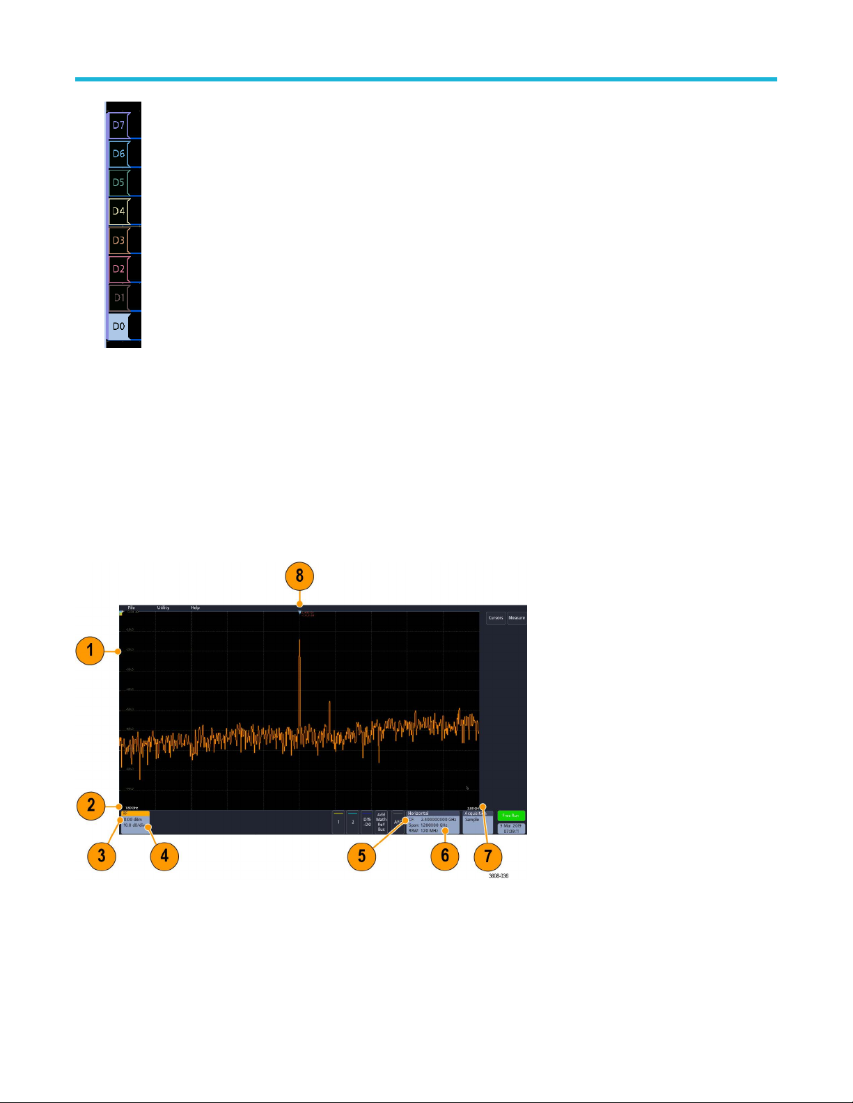
Double-tapping a digital waveform handle opens the digital channel configuration menu.
Getting acquainted with your instrument
Dragging a digital signal handle over another handle swaps location of the signals in the waveform view
handle out of the group, creates a new group. A selected digital group or signal handle can be moved using the Vertical Position
control.
. Dragging a digital signal
Identifying items in the frequency domain display
This topic shows and describes each element of the frequency domain display.
To activate the frequency domain display, press the front panel RF button or tap the RF button in the display .
Each area of the user interface has a specific function that helps manage information or controls.
ertical graticule labels
1. V
2. Start frequency
3. Reference level
4. Vertical scale
5. Center frequency
3 Series Mixed Domain Oscilloscope Printable Help 47

6. Span and resolution bandwidth
7. Stop frequency
8. Reference marker
9. Displayed trace indicators
a. An RF trace indicator is placed at the Reference Level.
b. A capital M appears if the maximum trace is turned on.
c. A capital A appears if the average trace is turned on.
d. A capital N appears if the normal trace is turned on.
e. The small m appears if the minimum trace is turned on.
Getting acquainted with your instrument
Orange highlighting indicates the currently selected trace. In the figures the small m, which stands for the minimum trace, is
highlighted. This indicates that the minimum trace is currently selected.
10. Normal trace: Each acquisition is discarded as new data is acquired.
1. Max hold trace: The maximum data values are accumulated over multiple acquisitions of the Normal trace.
1
12. Min hold trace: The minimum data values are accumulated over multiple acquisitions of the Normal trace.
13. Average trace: Data from the Normal trace is averaged over multiple acquisitions. This is true power averaging, which occurs before
the log conversion. Each power of 2 averaging reduces the displayed noise by 3 dB.
3 Series Mixed Domain Oscilloscope Printable Help 48

Getting acquainted with your instrument
Identifying items in the arbitrary function generator display
This topic shows and describes each element of the arbitrary function generator display
Each element of the arbitrary function generator display gives information about the generated function.
1. If visible, the output is on
2. AFG label
3. W
aveform type, such as Sine
4. Additive Noise icon
5. Frequency
6. Amplitude
7. Offset
.
Identifying items in the digital voltmeter display
This topic shows and describes each element of the digital voltmeter display.
Each element of the digital voltmeter display gives information about the measurement.
1.
Measurement type (AC+DC RMS, DC, AC RMS, or Frequency)
2. Numerical value of the current measurement
3. A
verage of all measurement values recorded since you powered on the instrument or since you last reset DVM statistics.
4. Maximum measurement value recorded since you powered on the instrument or since you last reset DVM statistics.
5. Minimum measurement value recorded since you powered on the instrument or since you last reset DVM statistics.
3 Series Mixed Domain Oscilloscope Printable Help 49

Getting acquainted with your instrument
Badges
Badges are rectangular icons that show waveform, measurement, and instrument settings or readouts. Badges also provide fast access to
configuration menus. The badge types are Channel, W
Channel and Waveform badges
Channel and Waveform (Math, Ref, Bus) badges are shown in the Settings Bar, located along the bottom left of the screen. Each
waveform has its own badge. The badges show high-level settings for each displayed channel or waveform. Double-tap a badge to open
its configuration menu.
Most Channel and Waveform badges also have Vertical Scale buttons, shown by single-tapping the badge. Use these buttons to increase
or decrease the vertical scale setting for that waveform.
aveform, Measurement, Search, and System.
You can drag or flick Channel and Waveform badges down off the display to turn them off. Swiping back up from the bottom of the display
restores them if they were accidentally deleted.
Channel badges are listed in the channel order
instrument Help.
. For more information, double-tap the badge to open its configuration menu or search the
Measurement badges
Result badges are located in the Results Bar. They show measurement or search results. The badge title also shows the measurement
source or sources. To add a Measurement badge, tap the Measure button, select a measurement, and tap Add.
Double-tap a Measurement badge to open its configuration menu to change or refine settings.
Some measurements and their badges are only available as options. For example, Power measurements are only listed in the Add
Measurement menu if the PWR option is installed.
3 Series Mixed Domain Oscilloscope Printable Help 50

Getting acquainted with your instrument
To add statistical readouts to individual measurement badges, double-tap a measurement badge to open its configuration menu and select
Show Statistics in Badge.
You can drag or flick Measurement badges off to the right of the display to delete them. You can bring the badge back by swiping in from
the right.
Search badges
Search badges are also shown in the Results Bar
and the number of search event occurrences in the current acquisition. The instrument marks the waveform where those events occur with
small down-pointing triangles along the top of the waveform graticule. Double-tap a search badge to open its configuration menu to change
or refine search settings.
Search badges are created by tapping the Search button. Use the displayed configuration menu to set the search criteria.
Search badges have < (Previous) and > (Next) Navigation buttons that open the Zoom mode and center the waveform in the display at the
position of the previous or next search mark in the waveform record. Search badge Navigation buttons are only usable when acquisitions
are stopped.
, below the Measurement badges. A search badge lists the search source, search type,
3 Series Mixed Domain Oscilloscope Printable Help 51

Getting acquainted with your instrument
You can drag or flick a Search badge to the right, off the display, to delete it. You can bring the badge back by swiping in from the right.
Signal clipping and badges
Clipping causes inaccurate amplitude-related measurement results. Clipping also causes inaccurate amplitude values in saved waveform
files. If a math waveform is clipped, it will not affect amplitude measurements on that math waveform.
Warning: Clipping is caused by excessive or dangerous voltages at the probe tip and/or a vertical scale setting that is not
adequate to display the entire vertical range of the waveform. Excessive voltage at the probe tip can injure the operator and cause
damage to the probe and/or instrument.
This instrument shows a warning triangle symbol and the word Clipping in a Channel badge when a vertical clipping condition
exists. Any measurement badges associated with that channel also indicate a clipping condition.
To close the clipping message, change the vertical scale to show the entire waveform, disconnect the probe tip from the excessive
voltage source, and check that you are probing the correct signal using the correct probe.
Error messages and badges
This instrument shows a warning triangle symbol and an error message abbreviation in a Channel badge when an error occurs.
To remove the message from the badge, clear the error.
System badges
System badges (in the Settings bar) display the main Horizontal, Trigger, and Acquisition settings. You cannot delete System badges.
3 Series Mixed Domain Oscilloscope Printable Help 52

Getting acquainted with your instrument
Double-tap a System badge to open its configuration menu.
The Horizontal badge also has Scale buttons, shown by single-tapping the badge. Use the Horizontal Scale buttons to increase or
decrease the horizontal time/div setting.
Common badge actions
Action Result Example
Single tap Immediate access controls (Scale,
Navigation).
Double tap Configuration menu with access to all
settings for the badge.
Touch and hold Right-click menu with single tap
access to common actions. T
actions include turning off a channel
and deleting a measurement or
search badge.
ypical
3 Series Mixed Domain Oscilloscope Printable Help 53

Configuration menus
Getting acquainted with your instrument
Configuration menus let you quickly set the parameters for channels, system settings (Horizontal, T
cursor readouts, Waveform view, and so on.
Double-tap an item (badge, Waveform View, cursor readouts, and so on) to open its configuration menu. For example, double-tap a
Channel badge in the Settings Bar to open its configuration menu.
Selections or values that you enter take effect immediately. Menu contents are dynamic and can change depending on your selections,
instrument options, or attached probes.
rigger, Acquisition), measurements,
Related settings are grouped into 'panels.' T
and/or fields shown in that panel and other panels.
Tap anywhere outside a configuration menu to close it.
o open Help content for a configuration menu, tap the question mark icon in the upper right corner of the menu.
T
ap the panel name to show those settings. Changes to panel settings can change the values
3 Series Mixed Domain Oscilloscope Printable Help 54

Zoom user interface elements
Use the zoom tools to magnify waveforms to view signal details.
Getting acquainted with your instrument
1. The Zoom Overview shows the entire waveform record.
Note: Using pinch and expand gestures on the Zoom Overview waveforms changes the horizontal time base settings.
2. The Zoom Box shows the area of the Zoom Overview to display in the Zoom View (see 4 on page 55). You can touch and drag the
box to move the area to view.
Note: Moving the Zoom Box or changing its position does not change the horizontal time base settings.
3. The Zoom icon (in the upper right corner of the W
4. The Zoom View shows the zoomed waveforms as marked by the Zoom Box. Use pinch and/or drag options in the zoom view to
change the zoomed area of interest.
Note: Pinch, expand, and drag gestures in the Zoom V
5. Use the Zoom T
the A and B multipurpose knobs. Double tap the zoom scale and position fields to enter a value using a numerical keypad.
itle Bar controls to adjust the horizontal size and the position of the zoom area. Click or tap the + or - buttons or use
Note: T
ouch the Zoom Position or Horizontal Zoom Scale fields before using the multipurpose knobs to adjust the zoom.
aveform View) switches zoom mode on and off.
iew only change zoom magnification settings and Zoom Box position.
Using the touchscreen interface for common tasks
Use standard touchscreen actions, similar to those found on smart phones and tablets, to interact with most screen objects. Y
use a mouse to interact with the UI. The equivalent mouse operation is shown for each touch operation.
ou can also
See the table to quickly learn the fundamental touch operations.
Table 14: Common touchscreen UI tasks (with mouse equivalents)
3 Series Mixed Domain Oscilloscope Printable Help 55

Getting acquainted with your instrument
Task Touchscreen UI action Mouse action
Add a channel, math, reference, or bus
waveform to the screen.
Tap an inactive channel button or the Add
Math Ref Bus button and select a math,
reference, or bus.
Select a channel, math, reference, or bus
waveform to make it active.
Display scale or navigation buttons on a
Tap the Channel or Waveform badge or
waveform handle.
Tap the badge. Click the badge.
badge (waveform, measurement 1, search,
horizontal).
Open a configuration menu on any item (all
Double-tap the badge, view, or other object. Double-click the badge, view, or other object.
badges, views, cursor readouts, labels, and
so on).
Open a right-click menu (badges, views). Touch and hold on the badge, Waveform
View, or other screen item until a menu
opens.
Close a configuration menu 2.
Tap anywhere outside the menu or dialog. Click anywhere outside the menu or dialog.
Move a menu. Touch and hold the menu title bar or a blank
area in the menu, then drag the menu to new
position.
Click an inactive channel button or the Add
Math Ref Bus button and select a math,
reference, or bus.
Click the Channel or Waveform badge or
waveform handle.
Right-click the object.
Click and hold the left mouse button on title
or blank area and then drag to new position.
Change horizontal or vertical settings directly
on a waveform.
V
ertical changes only apply to the selected
Tap a badge and use the Scale buttons. Or,
use pinch/expand gestures.
Click a channel, waveform, or Horizontal
badge and click on the Scale buttons.
channel or waveform; horizontal changes
apply to all channels and waveforms.
Increase or decrease the zoom area (while
in Zoom mode).
Adjust the zoom position (while in Zoom
mode).
Touch and hold two fingertips on the
waveform view, move them together or apart
vertically or horizontally, lift from screen, and
repeat.
Touch and drag in the zoom area to adjust
the position of the zoom.
Click and drag the zoom area.
Click the + or - buttons on the Zoom Title
bar.
Click and drag in the zoom area to adjust the
position of the zoom.
Quickly scroll or pan a waveform. Touch and drag in the waveform. Click and drag in the waveform or list.
Close or open the Results Bar to increase
the Waveform View area.
Tap on the Results Bar Handle or anywhere
in the border between the Waveform View
and the Results Bar.
Click the Results Bar Handle or anywhere
in the border between the Waveform View
and the Results Bar.
Click and drag the Results Bar divider.
1
Not all measurement or search badges display navigation buttons.
2
Some dialog boxes will not close until you click an OK, Close, or other button in the dialog.
3 Series Mixed Domain Oscilloscope Printable Help 56

Getting acquainted with your instrument
Accessing application help
Use the instrument online help to quickly get information about a function or assistance in performing a task.
Using context-sensitive help
o open help on a particular menu or item, tap the Help button (question mark symbol) in the title bar. The browser opens with content
T
relevant to the menu or item.
Navigating the online help
Select Help > Help to display the help browser is similar to PC-based Help tools. From the help browser, select one of the following tabs:
• Contents. Click any entry to display information on the subject.
• Index. Click an entry to display information on the subject.
3 Series Mixed Domain Oscilloscope Printable Help 57

Configure the instrument
Set the date and time
Set the date and time so that saved files are marked with the correct date and time information.
Procedure
Configure the instrument
1. Double-tap the Date/T
o turn off showing the date and time on the screen, tap the Display button to Off.
2. T
To turn on date/time display again, double-tap in the blank area where the date/time badge was displayed to open the configuration
menu and set the Display button to On.
3. You may also tap the Year, Day, Hour, Minute, or UTC Offset fields and use the multipurpose knobs to set the fields to the correct
time.
You may also double-tap the fields and use the numeric keypad to set the time.
4. Tap Month and select the month from the list.
5. Tap anywhere outside of the menu to close it.
ime badge (bottom-right of screen) to open the configuration menu.
Functional check
Use this procedure to quickly verify that the oscilloscope can display a waveform and take a measurement.
Procedure
1. Power on the oscilloscope.
2. Tap Utility > Self test. Check that all tests listed show Pass.
3. Connect an analog probe to the Channel 1 connector.
4. Connect the probe tip and ground lead to the probe compensation connectors.
5. Push the Autoset button. You should see a square wave in the display (approximately 2.5 V
6. Tap the Measure button.
7. Tap the Time Measurements panel in the Add Measurements configuration menu.
8. Double-tap the Frequency button and then the Add button to add the frequency measurement to the Results bar.
3 Series Mixed Domain Oscilloscope Printable Help 58
P-P
).

Configure the instrument
9. Check that the Frequency measurement reads 1 kHz
10. Repeat these steps to check the other channels on the oscilloscope. Make sure that you set the source in the Add Measurement
configuration menu to use the correct channel before adding the Frequency measurement.
Download and install the latest firmware
Installing the latest firmware helps ensure that your instrument is equipped with all of the best available measurement and analysis
improvements.
Before you begin
Prerequisite: Save any important on-instrument files (waveforms, screen captures, oscilloscope setups, and so on) to a USB drive or
network. The installation process does not remove user-created files, but it is a good idea to back up important files before an update.
Update oscilloscope firmware from a USB drive
Before you begin
Prerequisite: Determine the current version of firmware installed on the oscilloscope (Help > About)
Procedure
1. Open up a W
2. Enter the oscilloscope model number in the search field and click Go.
3. Scroll down the screen and click the Software tab.
4. If the listed available firmware version is newer than what is on your oscilloscope, select and download that file to your PC.
5. Copy the firmware install file to a USB drive.
6. Insert the USB drive into any oscilloscope USB Host port:
7. Power off the oscilloscope and then power on the oscilloscope.
The oscilloscopes detects the USB drive with the firmware file and starts the installation process. Follow on-screen instructions to
install the firmware.
8. When the firmware install is finished, remove the USB drive and restart the oscilloscope.
T
o confirm the firmware installation:
a. Tap Help > About in the Menu bar.
b. Verify that the firmware version number listed on the screen is the same version that you downloaded.
eb browser on a PC and go to www.tek.com/product-support.
Note: Do not power of
The oscilloscope displays a message when it is OK to turn off the oscilloscope.
f the oscilloscope or remove the USB flash drive until the oscilloscope finishes installing the firmware.
Run Signal Path Compensation (SPC)
Run SPC at regular intervals for best measurement accuracy. You should run SPC whenever the ambient (room) temperature has changed
by more than 5 °C (9 °F) or once a week if you use vertical scale settings of 5 mV/div or less.
About this task
Signal Path Compensation (SPC) corrects for DC level inaccuracies in the internal signal path caused by temperature variations and/or
long-term signal path drift.
Failure to run SPC on a regular basis may result in the oscilloscope not meeting warranted performance levels at low volts per division
settings.
3 Series Mixed Domain Oscilloscope Printable Help 59

Configure the instrument
Before you begin
Prerequisite: Disconnect all probes and cables from the front-panel channel inputs and rear-panel signal connectors.
Procedure
1. Power on and warm up the oscilloscope for at least 20 minutes.
ap Utility > Calibration.
2. T
3. Tap Run SPC. The SPC Status readout shows Running while SPC is running. SPC can take several minutes per channel to run, so
wait until the SPC Status message changes to Pass before reconnecting probes and using the oscilloscope.
4. Close the Calibration configuration dialog when SPC has completed.
5. If SPC fails, write down any error message text. Make sure that all probes and cables are disconnected and run SPC again. If SPC still
fails, contact Tektronix Customer Support.
Compensate TPP0250, TPP0500B, or TPP1000 probes
Probe compensation adjusts the high frequency response of a probe for best waveform capture and measurement accuracy. The
oscilloscope can automatically test and store compensation values for TPP0250, TPP0500B and TPP1000 probes.
About this task
The oscilloscope stores the compensation values for each probe/channel combination and automatically recalls the compensation values
when you plug in the probe again. Probe compensation status is shown in the Probe Setup panel of the Channel configuration menu.
• If the Probe Compensation Status field displays Pass, the probe is compensated and ready for use.
• If the Probe Compensation Status field displays Default, the attached probe has not been compensated and needs to have this probe
compensation procedure run.
• If the Probe Compensation Status field displays Fail, the attached probe has failed the probe compensation procedure. Reconnect the
probe and run probe compensation again.
• If there is no probe compensation status field shown in the panel, the oscilloscope cannot store compensation values for that probe.
See the oscilloscope Help for how to manually compensate passive probes not supported by the probe compensation function.
• Each compensation generates values for a specific probe and channel combination. If you want to use the probe on another channel
and desire to compensate the new probe-channel pair, you must run a new set of compensation steps.
• Each channel can store compensation values for 10 individual probes. If you try to compensate an 11th probe on a channel, the
oscilloscope will delete the values for the least recently used probe and add the values for the new probe.
Use this procedure to compensate a TPP0250, TPP0500B, TPP1000, or other supported TPP-family probe that shows a Default status
when connected to the oscilloscope.
Note: A Default Setup does not delete probe compensation values. A factory calibration deletes all stored probe compensation
values.
Before you begin
Prerequisite: The oscilloscope must be powered on for at least 20 minutes before compensating a probe.
Procedure
1. Connect a supported probe to an input channel.
2. Connect the probe tip and ground lead of the probe to the PROBE COMP terminals on the lower right of the oscilloscope (see
following image).
3 Series Mixed Domain Oscilloscope Printable Help 60
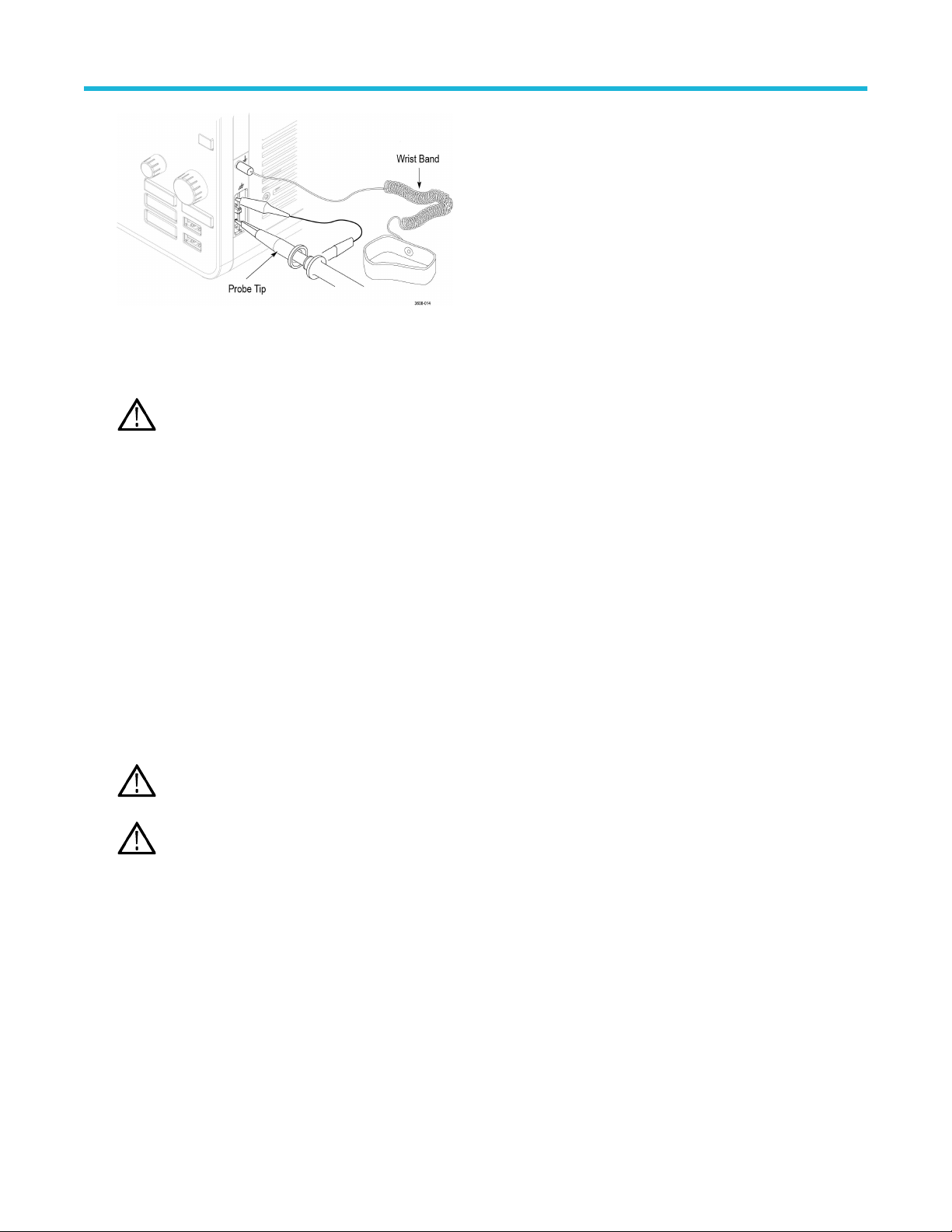
Configure the instrument
Figure 4: Probe Comp connections.
Connect the probe tip to the 1 kHz source and the ground clip to the ground. For best results, remove any probe tip accessories and
hold the probe tip directly onto the 1 kHz connector
Note: Connect only one probe at a time to the PROBE COMP terminals.
3. T
urn off all channels.
4. Turn on the channel to which the probe is connected.
5. Push the front-panel Autoset button. The screen displays a square wave.
6. Double-tap the badge of the channel that you want to compensate.
7. Tap the Probe Setup panel.
If the Probe Compensation Status says Pass, the probe is already compensated for this channel. You can move the probe to another
channel and start again from step 1 or connect a different probe to this channel and start from step 1.
.
If the Probe Compensation Status says Default, continue with this procedure.
8. Tap Compensate Probe to open the Probe Compensation dialog.
9. Tap Compensate Probe to run the probe compensation.
10. The probe compensation is finished when the Probe Compensation Status displays Pass. Disconnect the probe tip and ground from
the PROBE COMP terminals.
11. Repeat these steps for each supported passive probe that you want to compensate for this channel.
12. Repeat these steps to compensate supported probes on other channels of the oscilloscope.
Note: For most accurate measurements, open the Probe Setup panel and verify the Probe Compensation Status is Pass
whenever you attach a probe to a channel.
Note: A probe compensation failure is most likely due to intermittent connection of the probe tip or ground connection during
the probe compensation operation. If a failure occurs, the oscilloscope will re-use the old probe compensation values if they
existed prior to the failed probe compensation operation.
Compensate passive probes
Probe compensation adjusts the high frequency response of a probe for best waveform capture and measurement accuracy
procedure to adjust probe compensation for probes with a manual adjustment.
About this task
A passive probe is only adjusted for one channel at a time. If you move a passive probe to another channel, you must compensate that
probe to that channel.
. Use this
Procedure
1. Connect the probe to the channel where you want to use it to take measurements. Remove all other probes.
3 Series Mixed Domain Oscilloscope Printable Help 61

Configure the instrument
urn on the channel to which the probe is connected. Turn off all other channels.
2. T
3. Attach the probe tip and reference lead to the probe compensation connectors.
4. Push the Autoset button to display a square wave.
5. Adjust the vertical Scale and Position knobs to display as large a waveform as possible.
6. Use the adjustment tool provided with the probe to adjust the probe until the square wave has as flat a top as possible. See your probe
manual for adjustment location and instructions.
Connect to a network (LAN)
Connecting to a network allows you to remotely access the instrument.
Before you begin
ork with your network administrator to obtain the required information to connect to your network (IP address, Gateway IP address,
W
Subnet Mask, DNS IP address, and so on).
Procedure
1. Connect a CAT5 cable from the oscilloscope LAN connector to your network.
2. Select Utility > I/O on the menu bar to open the I/O configuration menu.
3. Tap the LAN panel
4. Obtain or enter the network address information:
• If your network is DHCP-enabled and the IP address field does not already show an address, tap Auto to obtain the IP address
information from the network. DHCP mode is the default mode.
• If your network is not DHCP-enabled or you need a static (non-changing) IP address for this instrument, tap Manual and enter the
IP address and other values provided by your IT or system administrator resource.
5. Tap Test Connection to verify that the network connection is working. The LAN Status icon turns green when the instrument
successfully connects to your network. If you have problems connecting to your network, contact your system administration resource
for help.
Mount a network drive
Use this procedure to mount (map) a network Linux mount point or Windows shared directory on a standard instrument.
Before you begin
Prerequisites:
The oscilloscope must be connected to a network that has access to the directories to mount or unmount. See the Connect to a network
(LAN) topic in the application Help.
To mount a Linux network drive on the oscilloscope, the network Linux mount point (drive, host) that you want to mount must be exported.
If the mount point is not exported, work with your organization's IT resource to get that location exported and accessible to your network.
About this task
To mount a network drive on your oscilloscope:
Procedure
1. Tap File > File Utilities.
3 Series Mixed Domain Oscilloscope Printable Help 62

Configure the instrument
ap Mount to open the Mount Network Drive menu.
2. T
3. Select the drive letter to assign to the network drive from the Drive Letter list.
4. Tap Name or IP to specify how you will enter the host name (server) of the network mount location or PC.
5. Enter the network host name or IP address of the Linux mount point or server in the Server Name or Server IP Address field.
Example: ACME-PC0205
6. Enter the path to the location of the mount point or shared directory of the server in the Path field.
• Linux example: /opt/testing/batch1 (Linux requires forward slashes in path definitions. Linux assumes that the path starts at the root
directory.)
7. If access to this network location is controlled, enter the required information in the User Name and Password fields.
8. Tap Enter. The oscilloscope mounts the drive and adds the specified drive letter to the File Utilities menu.
The oscilloscope displays an error message if it cannot mount the drive. Work with your organization's IT resource to verify that the
access information is correct and to resolve the network access problems.
Unmount a network drive
Use this procedure to unmount (remove) a network Linux mount point or Windows shared directory from a standard or Windows OS
instrument.
About this task
To unmount a network drive from your instrument:
Procedure
1. Tap File > File Utilities.
2. Select the drive to unmount.
3. Tap Unmount. The instrument unmounts the drive and removes it from the Drive column.
Note: Any network locations that were mounted when the oscilloscope was powered down will be automatically remounted
when the oscilloscope is powered up. Unmount any network location that you do not want to automatically remount on power
up.
Deskew analog input channels - quick visual method
Use the following procedure to visually align waveform edges to compensate for timing dif
About this task
Critical timing measurements on multiple channels require that all probes be adjusted, or deskewed, to compensate for signal timing
differences between probes. This procedure uses displayed waveform edges to quickly minimize deskew between probes.
Note: Once probes have been deskewed for a particular channel, you should only use the probes on the channels for which they
were deskewed, when taking critical timing measurements.
Procedure
1. Connect all probes that you want to deskew
2. Connect up to four probe tips and ground leads to the Probe Compensation connector (maximum of four channels at a time).
3. Turn on (display on screen) the connected channels that you want to deskew.
4. Push the Autoset button.
5. Adjust the vertical Scale and Position controls for each channel so that the signals overlap and are centered on the display.
6. Adjust the horizontal Scale so that the differences in the channel delays are clearly visible.
7. Determine the channel you want to use as your reference.
.
ferences between probes.
3 Series Mixed Domain Oscilloscope Printable Help 63

Configure the instrument
8. Double-tap the Channel badge of a channel other than the reference channel and tap the Other panel.
ap the Deskew field and use the multipurpose knob to align this channel with the reference channel waveform such that the
9. T
waveforms cross the trigger point at the same time. For fine adjust, double-tap the Deskew field to open a number pad.
10. Repeat steps 8 on page 64 and 9 on page 64 for each additional channel you want to deskew.
Deskew analog input channels - measurement method
Use the following procedure to more accurately minimize timing differences between probes.
About this task
Critical timing measurements on multiple channels require that all probes be adjusted, or deskewed, to compensate for signal timing
differences between probes. This procedure uses a Delay measurement to adjust a probe's deskew setting.
Note: Once probes have been deskewed for a particular channel, you should only use the probes on the channels for which they
were deskewed when taking critical timing measurements.
Procedure
1. Connect all probes that you want to deskew to the oscilloscope.
2. Connect up to four probe tips and ground leads to the Probe Compensation connector
3. Turn on all the channels that you want to deskew.
4. Push the Autoset button.
5. Change the vertical Scale of all active channels to 500 mV/div and adjust the vertical Position so that the waveforms are centered on
the display.
6. Determine the channel you want to use as your reference.
7. Tap the Measure button and tap the Time Measurements panel.
8. Select the Delay measurement, then tap the Add button.
9. Double-tap the Delay measurement badge and set your chosen reference channel as Source 1 and your channel being deskewed
as Source 2.
10. Double-tap the Channel badge of the channel being deskewed (Source 2) and tap the Other panel
11. Tap the Deskew field and use the multipurpose knob to align this channel with the reference waveform such that the measured delay
between channels becomes a minimum. For fine adjust, double-tap the Deskew field to open a number pad.
12. Double-tap the Delay measurement badge and set the Source 2 channel to the next channel to deskew.
13. Repeat steps 10 on page 64 through 12 on page 64 for each additional channel you want to deskew.
.
Connect a keyboard or mouse
The instrument supports most standard USB-connected keyboards and mice, including wireless-connected keyboards and mice (using a
USB-connected dongle).
About this task
You can use the keyboard to quickly create names or labels. Use the arrow keys on the keyboard to move the insertion point, and then
type in a name or label. Labeling channels and buses makes the information on the screen easier to identify.
Connect a keyboard and/or mouse by connecting their USB cable, or USB dongle, into any available USB Host port. The keyboard or
mouse should work immediately. If it does not, try the following:
Procedure
1. Remove and reinsert the USB cable or dongle in the same port.
2. Insert the USB cable or dongle into a different USB port.
3 Series Mixed Domain Oscilloscope Printable Help 64

Connect an external monitor or projector
Configure the instrument
Use the video outputs to send the instrument display to a projector or to a flat-panel LCD monitor
.
Procedure
1. Power on the oscilloscope.
2. Connect the appropriate video cable to the projector or monitor. Connect the other end to the HDMI connector on the oscilloscope.
3. Power on the projector or monitor.
4. Follow the projector or monitor instructions to set up and adjust the image.
ESD prevention guidelines
Electrostatic discharge (ESD) can damage oscilloscope and some probe inputs. This topic discusses how to avoid this type of damage.
ESD is a concern when handling any electronic equipment. The instrument is designed with robust ESD protection, however it is still
possible that large discharges of static electricity directly into the signal input may damage the instrument. Use the following techniques to
prevent electrostatic discharge from damaging the instrument.
• Discharge the static voltage from your body by wearing a grounded antistatic wrist strap while connecting and disconnecting cables,
probes, and adapters. The instrument provides a ground connection for attaching a wrist strap (above the Probe Comp ground
connector).
• A cable that is left unconnected on a bench can develop a large static charge. Discharge the static voltage from all cables before
connecting them to the instrument or device under test by momentarily grounding the center conductor of the cable, or by connecting a
50 Ω termination to one end, before attaching the cable to the instrument.
• Before you apply power, connect the instrument to an electrically-neutral reference point, such as earth ground. To do this, plug the
three-pronged power cord into an outlet grounded to earth ground. Grounding the oscilloscope is necessary to ensure safety and to
take accurate measurements.
• If you are working with static sensitive components, ground yourself. Static electricity that builds up on your body can damage
static-sensitive components. Wear a wrist strap to safely send static charges on your body to earth ground.
• The oscilloscope must share the same ground as any circuits that you plan to test.
3 Series Mixed Domain Oscilloscope Printable Help 65

Analog channel operating basics
Analog channel operating basics
Acquiring a signal
After acquiring a signal you can take measurements.
Use the following procedure to set the scale and position parameters for analog signal acquisition.
1. Press the Default Setup button.
2. Connect the probe output to the desired oscilloscope channel and connect the probe input to the input signal source using proper
probing/connecting techniques.
Note: Some probes automatically set their termination and other values.
3. T
ap the channel button to add the channel waveform to the waveform view and add a channel badge to the setting bar. A channel
button lights when its channel is on.
4. Double-tap the channel badge to open the channel Vertical Settings menu. To change the input coupling, select the appropriate
coupling button.
• Select DC to couple both the AC and DC components of an input signal.
• Select AC to couple only the AC components of an input signal.
5. Use the Vertical knobs to scale and position the waveform vertically on the screen. The knobs are highlighted with the color of the
active channel. Dragging the waveform handle also positions the waveform.
6. Use the Vertical Settings menu to change the offset. Tap Offset, then use a multipurpose knob to adjust the offset.
7. Use the Horizontal knobs to scale and position the waveform horizontally on the screen and to set the record length. Dragging the
trigger position icon or the waveform itself also positions the waveform.
8. Use the Horizontal menu to set the record length.
9. You may attempt to stabilize the display by pressing the trigger Level knob to set the trigger level to 50%. The 50% level is calculated
as the midpoint between the highest and lowest samples of the acquired waveform. If your signal is periodic, you should see a stable,
triggered signal. This method will not work as well with random signals.
Quickly display a waveform (autoset)
The Autoset function analyzes the signal characteristics and changes the instrument's Horizontal, Vertical, and Trigger settings to
automatically display a triggered waveform. You can then make further changes to trigger and horizontal settings to view the points of
interest.
Procedure
1. Connect the probe with the signal of interest to an available channel. The signal can be analog or digital.
2. Double-tap the Trigger badge and set the trigger source to that of the signal of interest.
3. Connect any other associated signal(s) to available channel input(s).
4. Add the channel waveforms to the Waveform view. See Add a channel waveform to the display on page 69.
5. Tap File > Autoset or push the front-panel Autoset button. The instrument analyzes the signal characteristics of the trigger source
channel (analog or digital) and adjusts the horizontal, vertical, and trigger settings accordingly to display a triggered waveform for that
channel.
3 Series Mixed Domain Oscilloscope Printable Help 66

Analog channel operating basics
What to do next
Autoset guidelines:
•
Autoset displays four or five cycles (depending on the detected signal) with the trigger level near the midlevel of the signal.
• The trigger is set to type Edge, rising slope, DC coupling.
• If no channels are displayed before pushing Autoset, the oscilloscope adds Ch 1 to the Waveform view whether it has a signal or not.
• Autoset ignores math, reference, and bus waveforms.
• A channel or waveform with a frequency less than 40 Hz is classified as no signal.
Set horizontal parameters
Use this procedure to set the horizontal time base parameters such as position, horizontal scale, and delay.
Procedure
1. Double-tap the Horizontal badge on the Settings bar to open the Horizontal configuration menu.
2. Use the menu selections to set horizontal parameters.
ap the Help icon on the menu title for more information on these settings.
3. T
How to trigger on a signal
Use this procedure to open the Trigger menu to select and configure the trigger event type and conditions.
Procedure
1. Double-tap the Trigger badge on the Settings bar to open the Trigger configuration menu.
2. Select a trigger from the Trigger Type list. The trigger type sets what fields are available in the menu and also updates the illustration
to show a graphic of the trigger type.
3 Series Mixed Domain Oscilloscope Printable Help 67

Analog channel operating basics
Note: To trigger on a bus, you must first add the bus to the Waveform view. See Add a math, reference, or bus
waveform on page 71
riggering on buses other than Parallel requires the purchase and installation of serial trigger and analysis options. See
Note: T
the Tektronix Web site for available serial trigger and analysis options.
3. Select the other fields to refine the trigger conditions. The menu fields and trigger graphic update as you make changes to the trigger
settings. Displayed fields depend on the selected trigger type. Selection changes take ef
fect immediately.
ap the Help icon on the menu title for more information on these settings.
4. T
5. Tap outside the menu to close the menu.
Set the acquisition mode
Use this procedure to set the method the instrument uses to acquire and display the signal.
Procedure
1. Double-tap the Acquisition badge on the Settings bar to open the Acquisition configuration menu.
2. Select the acquisition method from the Acquisition Mode list. Set any other parameters associated with the selected acquisition type.
3 Series Mixed Domain Oscilloscope Printable Help 68

3. T
ap the Help icon on the menu title for more information on these settings.
4. Tap outside the menu to close the menu.
Analog channel operating basics
Start and stop an acquisition
Acquisition controls the start and stop of waveform acquisition.
Procedure
1. To start an acquisition, double-tap the Acquisition badge and tap Run/Stop in the Acquisition configuration menu. You can also push
the Run/Stop button on the front panel.
2. T
o stop an acquisition, tap Run/Stop again or push the Run/Stop button.
3. To take a single acquisition, double-tap the Acquisition badge and tap Single/Seq in the Acquisition configuration menu or push the
Single/Seq button on the front panel.
4. The color of the Run/Stop and Single/Seq buttons on the front panel indicate the acquisition status (green = acquiring; red = stopped).
5. To clear the current acquisition data from waveform memory, double-tap the Acquisition badge and tap Clear in the Acquisition
configuration menu, or push the Clear button on the front panel.
Add a channel waveform to the display
Use this procedure to add a channel signal to the display.
Procedure
1. Connect signal(s) to the channel input(s).
2. Tap an Inactive Channel button (in the Settings bar) of a connected channel.
3 Series Mixed Domain Oscilloscope Printable Help 69

The selected channel is added to the Waveform View, and a Channel badge is added to the Settings bar.
3. Continue tapping Inactive Channel buttons to add more channels (digital or analog).
Analog channel operating basics
4. Double-tap a channel badge to open that channel's configuration menu to check or change settings.
waveform settings on page 70.
See Configure channel or
Configure channel or waveform settings
Use the channel and waveform configuration menus to set parameters such as vertical scale and offset, coupling, bandwidth, probe
settings, deskew values, external attenuation, and other settings.
Before you begin
Prerequisite: There is a channel or waveform badge in the Settings bar.
Procedure
1. Double-tap a Channel or Waveform badge to open a configuration menu for that item.
For example, in a Channel menu, use the Vertical Settings panel to set basic parameters such as vertical scale and position, offset,
coupling, termination, and bandwidth limit.
3 Series Mixed Domain Oscilloscope Printable Help 70

Analog channel operating basics
Available settings depend on the probe.
2. Tap the Probe Setup panel to confirm probe settings and run configuration or compensation on supported probes.
3. T
ap the Other panel to set probe deskew and external attenuation parameters.
ap the Help icon on the menu title to open the help topic for more information.
4. T
5. Tap outside the menu to close the menu.
Add a math, reference, or bus waveform
Math waveforms let you create new waveforms based on operations between two or more waveforms or by applying equations to
waveform data. A reference waveform is a static waveform record displayed for comparison. Bus waveforms let you view and analyze
serial or parallel data.
About this task
You can add 1 Math, 4 Reference (2 Reference on a 2 channel instrument), or 2 Bus waveforms to the Waveform View.
Procedure
1. Tap the Add Math Ref Bus button in the Settings bar and select from the available waveforms.
2. The instrument adds the waveform to the W
the Math waveform.
3 Series Mixed Domain Oscilloscope Printable Help 71
aveform view and adds a Waveform badge to the Settings bar. This example shows adding

Analog channel operating basics
3. Use the configuration menus to refine the waveform parameters. Displayed fields depend on the waveform and selections made in the
menu. Selection changes take ef
This example shows adding a Math waveform by using the Math Source fields to select Ch 1 and Ch 2 as the waveform sources,
setting the math type to Basic math operation, and subtracting channel 2 from channel 1.
fect immediately.
4. When adding a Reference waveform, if a reference is not defined, the instrument displays a Recall configuration menu. Navigate
to and select the reference waveform file (*.isf) to recall, then tap the OK, Recall W
Reference waveform.
5. Double-tap a math, reference, or bus badge to check or change that waveform's settings. See Configure channel or waveform
settings on page 70.
6. Tap the Help icon on a configuration menu title for more information on math, reference, and bus waveform settings.
7. Tap outside the menu to close the menu.
aveform button. The instrument displays the
Add a measurement
Use this procedure to select and add measurements.
Procedure
1. Acquire the channel(s) and/or waveform(s) on which you want to take measurements.
Note: Waveforms do not need to be displayed to be used for measurements as long as the channel or waveform badge is
on the Settings bar and is acquiring the signal to measure.
3 Series Mixed Domain Oscilloscope Printable Help 72

Analog channel operating basics
ap the Measure button to open the Add Measurements configuration menu.
2. T
Note: If the menu shows tabs, then optional measurement types have been installed on the instrument. Select a tab to show
the measurements for that option.
Note: If frequency domain (RF) is active, tapping the Measure button opens the Add Measurements configuration menu
.
for RF
3. T
ap the Source field and select the measurement source. The list shows all available sources that are valid for the measurement.
4. Select from the configuration menu panels, such as Amplitude Measurements, T
measurements for those categories.
5. Select a measurement and tap Add to add the measurement to the Results bar.
6. Select and add other measurements for the current source. Tap the measurement category panels to display and select other
measurements to add.
7. To add measurements for other sources, select a different source, select a measurement, and add the measurement.
iming Measurements, and Other, to display
3 Series Mixed Domain Oscilloscope Printable Help 73
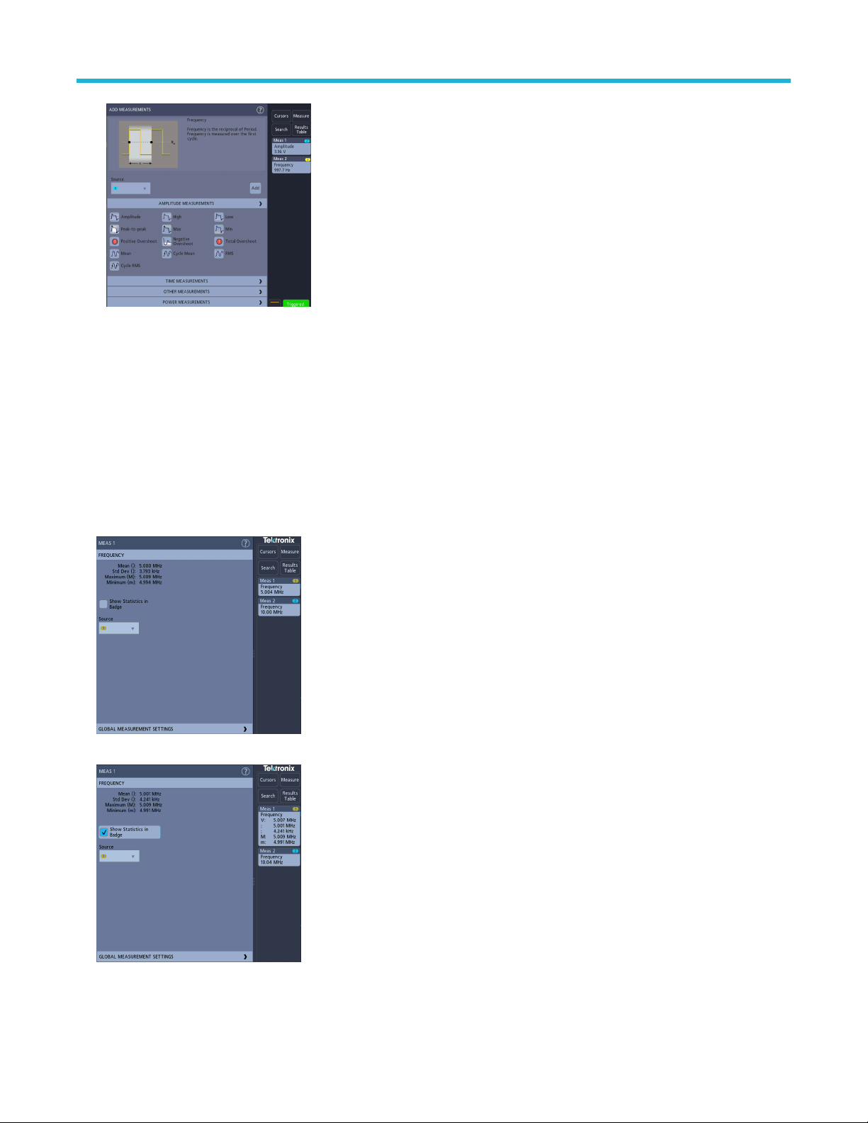
Analog channel operating basics
ap outside the Add Measurements menu to close the menu.
8. T
9. To further adjust a measurement's settings, double-tap a measurement badge to open a configuration menu for that measurement.
See Configure a measurement on page 74.
10. Tap the Help icon on the menu title for more information on settings.
Configure a measurement
Use this procedure to add statistical readouts to the measurement badge and refine measurement parameters (configuration, global
versus local scope of settings, gating, and so on).
Procedure
1. Double-tap a measurement badge to open its Measurement configuration menu.
2. T
ap Show Statistics in Badge to add statistical readouts to the measurement badge.
3. T
ap available panel titles to make changes for those categories.
3 Series Mixed Domain Oscilloscope Printable Help 74

Analog channel operating basics
4. Use the available fields to refine the measurement conditions. Displayed fields depend on the measurement. Selection changes take
ef
fect immediately. Selection changes can also change fields in other panels.
5. Tap the Help button on the menu title for more information on this menu's settings.
6. Tap outside the menu to close the menu.
Delete a measurement or search badge
Use this procedure to remove a Measurement or Search badge from the Results bar.
Procedure
1. Touch and hold the Measurement or Search badge that you want to delete. The instrument opens a right-click menu.
2. Select Delete Meas or Delete Search to delete that badge from the Results bar.
ou can also delete a Measurement or Search badge by dragging it off the display. You can use the mouse to drag and delete a badge.
3. Y
Display an XY waveform
Use this procedure to display an XY waveform.
About this task
XY display mode displays the amplitude from one waveform against the amplitude from another.
Procedure
1. Double-tap the Acquisition badge.
The Acquisition configuration menu is displayed.
2. Tap XY Display to toggle the mode on or off.
Results
A data point from the first waveform specifies the horizontal location while the corresponding data point from the second waveform
specifies the vertical location for each displayed point.
3 Series Mixed Domain Oscilloscope Printable Help 75

Analog channel operating basics
Display an FFT math waveform
Use this procedure to display an FFT math waveform.
About this task
The FFT process mathematically converts the standard time-domain signal (repetitive or single-shot acquisition) into its frequency
components. The FFT function processes the waveform record and displays the FFT frequency domain record, which contains the input
signal frequency components from DC (0 Hz) to ½ the sample rate (also called the Nyquist frequency).
Procedure
ap Add Math Ref Bus and then tap Math.
1. T
2. Double-tap the Math badge to open the Math configuration menu.
3. Tap Source and select the signal source from the list.
4. Set Math Type to FFT.
The FFT of the waveform is displayed in an FFT Math waveform view.
5. Use the controls to further refine the FFT display.
Add a search
Use this procedure to set search criteria and mark a waveform where those events occur.
About this task
You can search on analog and digital signals, math waveforms, and reference waveforms.
Prerequisite: Display the channel or waveform signal on which to search. The waveform must be displayed to create a search for it.
Procedure
1. Display the channel or waveform signal on which to search. The waveform must be displayed to create a search for it.
2. Tap the Search button to open the Search configuration menu.
3. Use the configuration menu fields to set the search criteria in the same way that you would set for a trigger condition (select the
Search T
4. The searched waveform is marked with one or more triangles as soon as the search criteria becomes true. The example image shows
search criteria set to find positive pulse widths that are less than 70 ns wide.
ype, Source, and conditions on which to search).
3 Series Mixed Domain Oscilloscope Printable Help 76

Analog channel operating basics
o stop showing marks on a waveform, double-tap the Search badge and tap Display to Off.
5. T
6. To move the waveform to center marks on the display, push the Run/Stop front panel button to stop acquisition, single-tap a Search
badge, and tap the < or > Navigation button.
This opens the Zoom mode and moves the waveform to the previous or next event mark on the waveform.
7. T
o return the instrument to normal acquisition mode, tap the Zoom icon in the upper right corner of the Waveform View to turn off
Zoom mode, and then push the Run/Stop front-panel button to set it to Run mode.
Change waveform view settings
Use this procedure to change the waveform persistence, style, and intensity; graticule style and intensity; and screen annotation.
Procedure
1. Double-tap on an open graticule area to open the Waveform View configuration menu.
2. Use the controls to set the waveform point persistence, style, and intensity
3. Tap the Help icon on the menu title to open the Waveform View menu help topic for more information on the waveform view
parameters.
4. Tap outside the menu to close the menu.
, graticule style and intensity, and screen annotation.
3 Series Mixed Domain Oscilloscope Printable Help 77
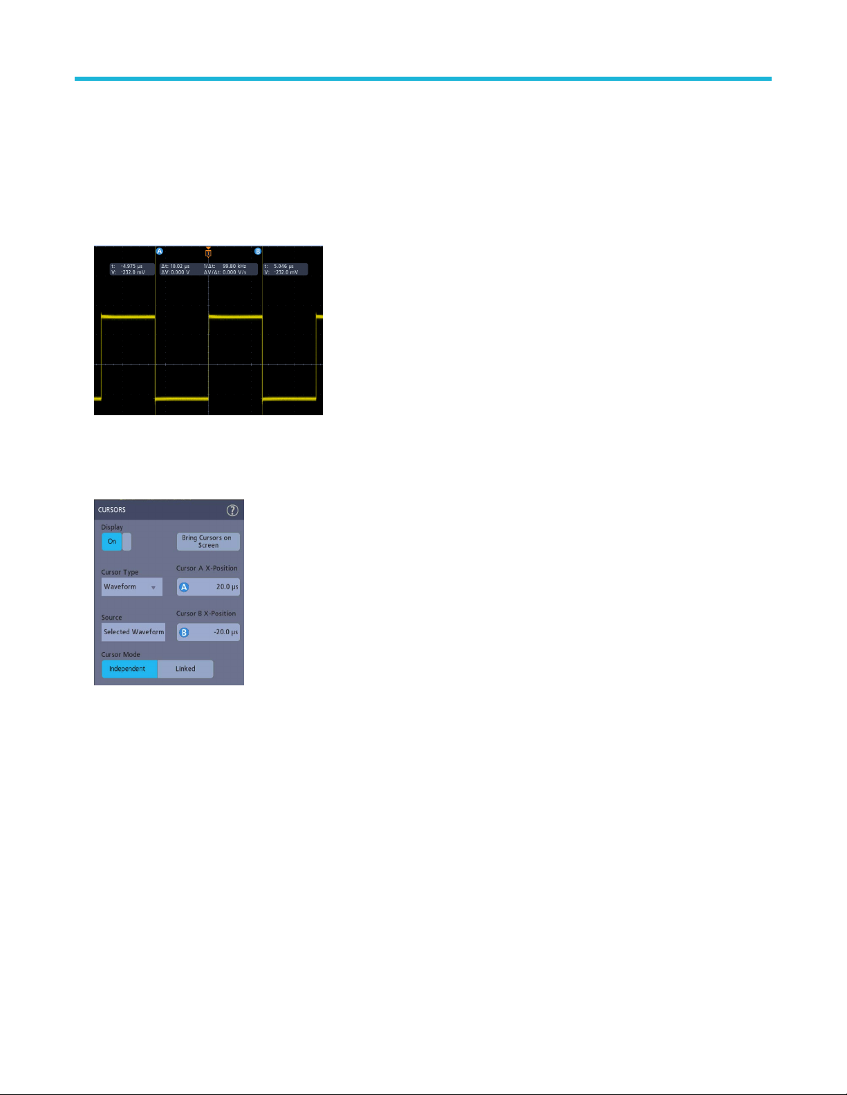
Analog channel operating basics
Display and configure cursors
Cursors are on-screen lines that you can move to take measurements on specific parts of a waveform. Cursor readouts show both current
position values and the dif
Procedure
1. Tap the Cursors button, or push the front-panel Cursors button.
The cursors are added to the display.
ference (delta) between cursors.
2. Use Multipurpose Knobs A and B or touch and drag to move the cursors. Cursors show readouts that show position and dif
measurements between the cursors.
3. To further configure cursors, double-tap on either cursor line or the cursor readouts to open the Cursors configuration menu. For
example, tap the Cursor type to select the cursors to display, such as Waveform.
4. T
ap the Help icon on the menu title for more information on the menu settings.
5. To stop showing cursors, push the front panel Cursor button or open the Cursors configuration menu and set Display to Off.
ference
Using Default Setup
Use Default Setup to restore instrument settings to their factory defaults.
Procedure
1. Press the front panel Default Setup button to return the instrument to its factory default settings (horizontal, vertical, scale, position,
and so on).
3 Series Mixed Domain Oscilloscope Printable Help 78

Analog channel operating basics
ou can also select File > Default Setup to restore default settings.
2. Y
Using Fast Acq
Fast Acq (fast acquisition mode) reduces the dead time between waveform acquisitions, enabling the capture and display of transient
events such as glitches or runt pulses. Fast acquisition mode can also display waveform occurrences at intensity levels that reflect their
rate of occurrence.
Procedure
1. To use Fast Acquisition mode, double-tap the Acquisition badge. Tap Acquisition mode and select Fast Acq from the list. You can
also push the Fast Acq front-panel button.
2. T
o display waveform phenomena at an intensity that reflects their rate-of-occurrence, after selecting the Fast Acq acquisition mode,
tap Fast Acq Palette and select a display palette from the drop-down list.
3. Fast Acq displays waveform phenomena at an intensity that reflects their rate-of-occurrence
3 Series Mixed Domain Oscilloscope Printable Help 79
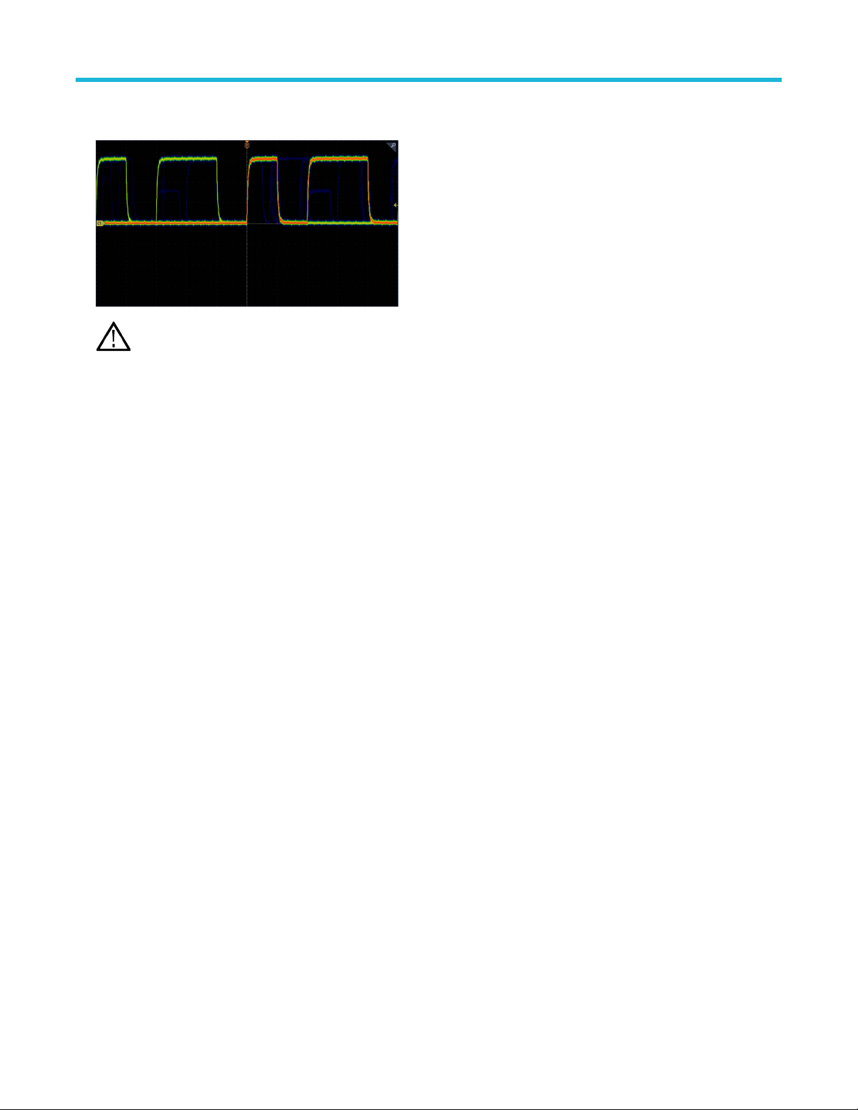
Analog channel operating basics
iew the waveform to find glitches, transients, or other random events. When you have identified an anomaly, use the advanced trigger
4. V
system to capture the event of interest for further analysis.
Note: If Fast Acquisitions mode is on and you attempt to activate a feature that conflicts with this mode, Fast Acquisitions
mode will be disabled. When the conflicting feature is turned of
f, Fast Acquisitions will resume in most cases.
Remote access from a Web browser
ou can remotely access your network-connected instrument from a Web browser to display the instrument user interface on a PC.
Y
About this task
This procedure describes how to remotely access the UI controls and screen for the instrument.
Before you begin
Prerequisites:
• The oscilloscope must be connected to, and accessible from, the network to which the PC is connected. See Connect to a network
(LAN) on page 62
• Determine the IP address of the oscilloscope that you want to access. To determine the oscilloscope's IP address, select Utility > IO in
the oscilloscope menu bar and view the network settings in the LAN panel.
Procedure
1. Open a Web browser on a PC connected to the same network as the oscilloscope.
2. Enter just the oscilloscope IP address on the URL line of the browser and press Enter. For example: 135.62.88.157. The browser
searches for and opens the Web page for the oscilloscope.
Connect the oscilloscope to a PC using a USB cable
Use a USB cable to connect the oscilloscope directly to a PC for remote instrument control.
Procedure
1. On the oscilloscope, select Utility > I/O from the menu bar.
2. Tap USB Device Port.
3. Confirm that the USB Device Port control is On (default setting).
4. Connect a USB cable from the PC to the USB Device port on the rear of the instrument.
5. If using the USB connection to remotely control the oscilloscope using GPIB commands, set the GPIB Talk/Listen Address for your
configuration (0 - 30).
3 Series Mixed Domain Oscilloscope Printable Help 80
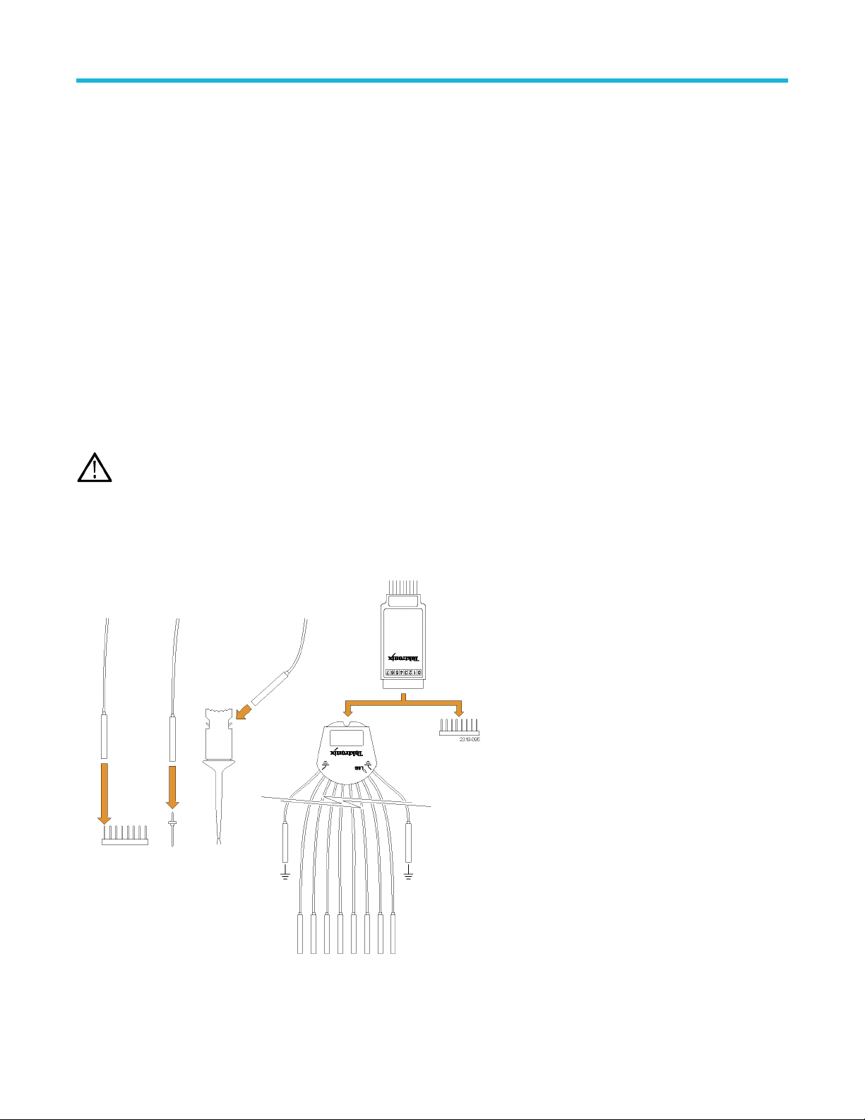
Acquiring digital signals
Acquiring digital signals
Acquiring digital signals
Connect a P6316 logic probe to digital input. Connect the logic probe inputs to the DUT (see the probe instructions). Then use the
following topics to set up, acquire, and display digital signals.
• Connect and set up digital signals on page 81
• Add a serial bus to the W
• Add a parallel bus to the Waveform view on page 84
Connect and set up digital signals
Use the digital Channel configuration menu to set up the digital channels to acquire signals.
About this task
Digital channel configuration menus are available only if a supported digital logic probe is attached to the oscilloscope.
aveform view on page 82
CAUTION: T
and DUT. Always observe the maximum input voltage ratings for input connectors.
o prevent damage to the instrument always wear an antistatic wrist strap when making connections to the instrument
Procedure
1. Connect the logic probe to the instrument. T
2. Connect the probe to the signal sources. Use the accessories in the Tektronix Probe accessory Kit (shipped with the probe) to connect
to your DUT.
ap the D15-D0 . The digital signal waveforms are opened on the screen.
3. Double-tap the D15-D0 button to open the Digital configuration menu. Set up digital channels to match your digital logic requirements.
3 Series Mixed Domain Oscilloscope Printable Help 81

Acquiring digital signals
ap Display to toggle the digital channel group On or Off.
4. T
5. To change the displayed height of the digital channels, tap a Height button.
6. Tap a Bit control to toggle individual digital channel bits On or Off and remove them from the displayed logic waveform.
7. Tap a Threshold field and use multipurpose knob A to set bit threshold levels. You can also set the thresholds by double-tapping the
field and setting the threshold using the virtual keypad.
8. Use the bit Label fields to enter labels for the individual digital channel bits (D0-D15). Double-tap on the field and use the virtual
keyboard to enter label text. Or tap the field and use an attached keyboard to enter label text.
9. Tap Turn All Off to turn all digital bits Off (D15-D7 or D7-D0).
Add a serial bus to the Waveform view
Use this procedure to add a serial bus to the Waveform view.
This instrument supports decoding parallel buses (standard with the instrument) and several serial buses options (see Serial bus decode
and trigger options on page 26). All serial bus functions are options that must be purchased and installed before they are available in the
instrument menus.
Use a Bus configuration menu to define a bus from which to acquire, decode, and display data.
Procedure
1. Tap the Add Math Ref Bus button on the Settings bar and then tap Bus to add a Bus badge to the Settings bar and add a bus
waveform to the screen. The default bus type is parallel.
3 Series Mixed Domain Oscilloscope Printable Help 82

2. Double tap the Bus badge to open the Bus Configuration menu.
ap Bus Type and select the bus type from the drop-down list.
3. T
Acquiring digital signals
4. Use the fields and controls to select the bus signal sources, thresholds, other parameters, and the output format. The following
example shows the settings for an I2C serial bus.
3 Series Mixed Domain Oscilloscope Printable Help 83

The decoded bus is updated on the screen as you make changes to the settings.
ap outside of the Bus configuration menu to close it.
5. T
6. Double-tap the Trigger badge and use the Trigger configuration menu to trigger on a specific condition in the bus.
Acquiring digital signals
7. For more information on serial bus settings, tap the Help button on the Bus configuration menu.
Add a parallel bus to the W
Use this procedure to add a parallel bus to the Waveform view.
When you acquire data from a Parallel bus, you can set up the bus to be clocked or unclocked. If the bus is not clocked, the instrument
acquires all data from the parallel bus at the sample rate of the instrument.
aveform view
Procedure
1. Tap the Add Math Ref Bus button on the Settings bar and then tap Bus to add a Bus badge to the Settings bar and add a bus
waveform to the screen. The default bus type is parallel.
2. Double tap the Bus badge to open the Bus Configuration menu.
3 Series Mixed Domain Oscilloscope Printable Help 84

3. If setting up a clocked bus:
Acquiring digital signals
a) Set Clocked Data to Y
b) Tap the Clock Source field and select the source for the parallel bus clock signal.
c) Tap the Clock Polarity and Threshold controls and set the clock signal transition to detect and threshold level, respectively.
4. Tap Define Inputs and select the signal sources for the parallel bus. Signal sources can be analog or digital. Tap a signal in the
Sources list to add it to the bus list on the left.
es.
3 Series Mixed Domain Oscilloscope Printable Help 85

Acquiring digital signals
The bus waveform updates as you make changes on the configuration menu. Tap the + symbol next to the waveform handle to turn on
f showing the signals associated with the bus waveform.
and of
5. Use the rest of the fields and controls in the configuration menu to set up the parallel bus parameters (label, position, display and
decode formats).
6. T
ap outside of the Bus configuration menu to close it.
7. To get a stable triggered waveform, double-tap the Trigger badge, set the Trigger Type to Bus, select the bus Source to the parallel
bus you just set up, and enter the data condition on which to trigger in the Data field.
8. For information on parallel bus menu settings, tap the Help button on the Bus configuration menu.
3 Series Mixed Domain Oscilloscope Printable Help 86

Advanced triggering
Advanced triggering
Advanced triggering
ou can check the advanced trigger status in the trigger menu. The menu indicates the trigger type and then shows sources, levels, or any
Y
other parameters that are important for the particular trigger type. Use the following links for more information on advanced triggering.
• Triggering concepts on page 87
• Set Trigger Holdoff on page 88
• Trigger on sequential events (A and B triggers) on page 89
• Set up trigger on a parallel bus on page 89
• Set up trigger on a serial bus on page 90
Triggering concepts
Overview
User selected trigger conditions are used to capture waveforms for measurement and analysis.
Triggers help you capture meaningful waveforms to display on screen. This instrument has simple edge triggers as well as a variety of
advanced triggers.
The trigger event
The trigger event establishes the time-zero point in the waveform record. All waveform record data are located in time with respect to that
point. The instrument continuously acquires and retains enough sample points to fill the pretrigger portion of the waveform record (that part
of the waveform that is displayed before, or to the left of, the triggering event on screen).
When a trigger event occurs, the instrument starts acquiring samples to build the posttrigger portion of the waveform record (displayed
after, or to the right of, the trigger event). Once a trigger is recognized, the instrument will not accept another trigger until the acquisition is
complete and the holdoff time has expired.
Trigger on a pulse width event
Pulse-width triggering triggers the instrument when a signal pulse width is less than, greater than, equal to, or not equal to a specified
pulse width. This trigger is useful for digital logic troubleshooting.
About this task
To set a pulse width trigger:
Procedure
1. Double-tap the Trigger badge to open the Trigger configuration menu.
2. Tap Trigger Type and select Pulse Width.
3. Tap Source and select the trigger source.
4. Tap Trigger When and select the pulse width condition on which to trigger (> Limit, < Limit, = Limit, ≠ Limit, Outside Range,
Inside Range).
3 Series Mixed Domain Oscilloscope Printable Help 87

Advanced triggering
5. Set the pulse width time constraints:
a) For all Trigger When conditions except Outside Range or Inside Range, tap the Time Limit field and use the assigned
multipurpose knob to set the pulse width time condition to meet.
b) For Outside Range or Inside Range conditions, tap the High Time Limit and Low Time Limit fields and use the assigned
multipurpose knobs to set the pulse width time range condition to meet.
6. Tap the Level field and set the threshold value at which you want to measure pulse width.
7. Select the pulse polarity on which to trigger.
Set Trigger Holdoff
Trigger Holdoff sets the time, after triggering on an event, that the instrument waits before detecting the same trigger event to start the next
acquisition.
About this task
Setting the correct holdoff time is important to get a stable trigger. The longer holdoff time for the top waveform causes unstable triggering.
The shorter holdoff set for the bottom waveform only triggers on the first pulse in the burst to remedy the unstable trigger.
Procedure
1. Double-tap the T
2. Tap the Mode & Holdoff panel.
3. To set a specific holdoff time, tap Holdoff and use the assigned multipurpose knob to specify a holdoff time. Or double-tap the field and
use the virtual keypad to enter a holdoff time.
rigger badge on the Settings bar to open the Trigger configuration menu.
3 Series Mixed Domain Oscilloscope Printable Help 88

Trigger on sequential events (A and B triggers)
Advanced triggering
Use the A and B T
rigger Events to trigger on a second event after a first event occurs.
Set up sequential triggering
Procedure
1. Double-tap the Trigger badge to open the Trigger configuration menu.
2. Tap Trigger Type and select Sequence. Sequence triggering uses Edge triggering for both the A and B trigger types.
3. Set up the A Trigger Event:
a) Tap A Source and select the A event trigger source.
b) If displayed, tap Coupling and select the trigger coupling.
c) Tap A Level and set the desired trigger level using the multipurpose knob. Or double-tap the field to set the value using the virtual
keypad.
d) Tap a A Slope button to select the slope of the signal on which to trigger (Rise or Fall).
4. Set up the B Trigger Event:
a) Tap B Source and select a trigger source.
b) Tap B Level and set the desired trigger level using the multipurpose knob. Or double-tap the field to set the value using the virtual
keypad.
c) Tap a B Slope button to select the slope of the signal on which to trigger (Rise or Fall).
5. To trigger on a specific occurrence of the B trigger event:
a) Tap After the A Trigger Event is found: Trigger on the Nth Trigger Event button in the main Trigger menu.
b) Tap Where N is: and use the multipurpose knob to set the oscilloscope to trigger on the Nth occurrence of a B trigger event.
6. To trigger on the B event after a specific time delay:
a) Tap After the A Trigger Event is found: Trigger on the 1st B Event button.
b) Tap After a Delay of: and use the multipurpose knob to set the desired delay time to wait before detecting and triggering on a B
trigger event. You can also double-tap the field and use the virtual keypad to enter a delay time.
Set up trigger on a parallel bus
Use this procedure to set up triggering on a parallel bus.
Before you begin
Use this procedure if you have already created a parallel bus.
Procedure
1. Double-tap the Trigger badge.
2. Tap the Trigger Type field and select Bus from the list.
3. Tap the Source field and select the parallel bus on which to trigger.
4. Tap either the Binary or Hex Data boxes to enter the parallel bus data value, in either Binary or Hexadecimal format, on which to
trigger. The number of bits shown depends on the number of sources (channels) in the parallel bus.
a) Use multipurpose knob A to select the digit or digits to change.
b) Use multipurpose knob B to change the value of the selected digits.
3 Series Mixed Domain Oscilloscope Printable Help 89

Advanced triggering
Set up trigger on a serial bus
Use this procedure to set up triggering on a serial bus.
Before you begin
Use this procedure if you have already created a serial bus. Serial buses require the purchase and installation of serial bus options. See
Serial bus decode and trigger options on page 26.
Procedure
1. Double-tap the T
2. Tap Trigger Type and select Bus from the list.
3. Tap Source and select a serial bus from the list.
4. Tap Trigger On and select what to trigger on from the list. The displayed fields and controls depend on the bus type and Trigger On
selection. Use these fields to trigger on a specific bus condition.
rigger badge on the Settings bar.
Trigger using the AUX input
Use this procedure to trigger the instrument from an external signal connected to the AUX input.
Procedure
1. Double-tap the Trigger badge on the Settings bar.
2. Tap Trigger Type and select Edge from the list.
3. Tap Source and select Aux.
Note: Aux is available only on 2 channel instruments and for the Edge trigger type.
4. Set the values for Coupling, Level, and Slope to trigger on the Aux connector signal.
3 Series Mixed Domain Oscilloscope Printable Help 90

Setting waveform display parameters
Setting waveform display parameters
Setting waveform display parameters
Use waveform display controls to set the persistence, style, and intensity display parameters, and graticule style and intensity
Use the following topics for more information on setting display parameters.
• Set the waveform persistence style and intensity on page 91
• Set the graticule style and intensity on page 91
.
Set the waveform persistence style and intensity
Use the Waveform View configuration menu to set waveform persistence, style, and intensity.
Procedure
1. Double-tap on an open graticule area to open the Waveform View menu.
2. Tap the Persistence field to select the persistence option.
• Off disables display persistence.
• Auto lets the oscilloscope automatically determine a persistence time for you.
• Infinite persistence continuously accumulates record points until you change one of the acquisition display settings. Use infinite
persistence for displaying unique signal anomalies, such as glitches.
• Variable persistence accumulates record points for a specified time interval. Each record point decays independently according to
the time interval. Use variable persistence for displaying infrequently appearing signal anomalies, such as glitches.
If you select Variable persistence, tap Variable Persistence and set the time using the multipurpose knob or double-tap the field
and use the virtual keypad to enter the time value.
3. Tap the Waveform Style buttons to set waveforms to draw as vectors (continuous lines) or dots.
• Vectors displays the waveform with the waveform sample values connected by vectors.
• Dots displays the individual waveform sample values.
4. Tap the Waveform Intensity field and use the multipurpose knob to set the brightness of all waveforms.
Set the graticule style and intensity
Use this procedure to set the graticule (display grid) style and intensity.
Procedure
1. Double-tap on an open graticule area to open the Waveform View configuration menu.
2. Tap the Graticule Style field to select a graticule style from the list.
Full shows a frame, cross hairs, and a grid on the instrument display. This style is useful for making quick, full-screen measurements
with cursors and automatic readouts when cross hairs are not needed.
Grid, Solid, and Cross Hair provide compromises between Frame and Full.
Frame provides a clean screen on which you can most easily read automatic measurement results and other screen text.
3. Tap the Graticule Intensity field and use the multipurpose knob to set the brightness of all graticules.
3 Series Mixed Domain Oscilloscope Printable Help 91

Zooming on waveforms
Zooming on waveforms
Zooming on waveforms
Use the zoom tools to magnify waveforms to view signal details.
Turn on Zoom mode
Zoom mode lets you look at a portion of your waveform in greater detail. Enable Zoom mode and touch and drag on-screen to select the
area to zoom.
About this task
To enable Zoom mode, do the following:
Procedure
1. Tap the Zoom icon in the corner of display.
2. Zoom overview:
a. To use Zoom once enabled, use pinch and/or drag options in the zoom view to change the zoomed area of interest.
Note: Pinch, expand, and drag gestures in the Zoom View only change zoom magnification settings and Zoom Box
position.
Use the A and B multipurpose knobs to adjust the scale and position of the zoom from the front panel controls. Select
either the Horizontal Zoom Scale or the Zoom Position field to assign knob A and B for zoom adjustment. A and B icons
are displayed in the field when a knob is assigned.
b. To exit the zoom display mode, tap the Zoom icon in the corner of display or tap the X in the Zoom Title Bar.
3. For more information on zoom:
• Zoom user interface elements on page 55
• Zoom mode and Searches on page 92
Zoom mode and Searches
Use Zoom and Searches to find events of interest on a waveform.
About this task
Searches provide a way to mark a waveform event or events for reference. You can set marks automatically with search criteria such as
particular edges, pulse widths, runts, logic states, rise/fall times, setup and hold, and bus data types.
When in Zoom mode, you can tap the Search badge and use its navigation buttons to position the waveform to the previous or next search
marks.
3 Series Mixed Domain Oscilloscope Printable Help 92

Zooming on waveforms
For information on creating a Search, see Add a search on page
76.
3 Series Mixed Domain Oscilloscope Printable Help 93

Customizing measurements
Customizing measurements
Customizing measurements
After adding a measurement, you can customize the measurement for more precise results by using gating or setting reference levels.
o customize measurements, double-tap a Measurement badge in the Results bar to open the Measurement configuration
T
menu on page 111.
See the following topics for more information.
• Reference levels determine how time-related measurements are taken. See Set measurement reference levels on page 94.
• Gating confines the measurement to a certain portion of a waveform. See Set measurement gates on page 94.
Set measurement reference levels
Use this procedure to set measurement reference levels.
About this task
Reference levels are set in the Global Measurement Settings panel of the Measurements configuration menu. See Measurement
configuration menu on page 111.
Before you begin
Prerequisite: To set measurement reference levels you must be taking a measurement. See Add a measurement on page 72.
Procedure
1. Double-tap a Measurement badge.
The Measurement configuration menu is displayed.
2. Tap the Global Measurement Settings panel.
3. Tap Reference Levels and select either % or Units.
• % sets the High, Mid, and Low reference levels as percentages of the calculated High and Low signal levels. Tap the High Ref,
Mid Ref, or Low Ref fields and set the level using the assigned multipurpose knob. Or double-tap the field and use the virtual
keypad to enter a value.
• Units sets the High, Mid, and Low reference levels to specific signal levels. Tap the High Ref, Mid Ref, or Low Ref fields and set
the level using the assigned multipurpose knob. Or double-tap the field and use the virtual keypad to enter a value.
4. Tap High-Low Method and select the method.
• Auto automatically chooses the method.
• Hysteresis is best for pulses.
• Min-Max is best for all other waveforms.
5. Tap anywhere outside the Measurement configuration menu to close it.
Set measurement gates
Use this procedure to specify which portion of your waveform is used to take measurements.
About this task
Gating is set in the Global Measurement Settings panel of the Measurements configuration menu. See Measurement configuration
menu on page 111.
3 Series Mixed Domain Oscilloscope Printable Help 94

Customizing measurements
Before you begin
o set measurement gates you must be taking a measurement. See Add a measurement on page 72.
T
Procedure
1. Double-tap a measurement badge to open the Measurement configuration menu.
2. Tap the Global Measurement Settings panel.
3. Tap Gating and either Off, Screen, or Cursors gating:
• Off takes measurement across the entire waveform record.
• Screen takes measurements on that portion of the waveform shown in the display. When Zoom is on, the display is the zoom
window.
• Cursors takes measurements on that portion of the waveform between the cursors. Selecting Cursors opens cursors on the
measurement source. Set the cursors so that the waveform area of interest is between the cursors.
4. Tap anywhere outside the Measurement configuration menu to close it.
3 Series Mixed Domain Oscilloscope Printable Help 95

Saving and recalling information
Saving and recalling information
Use these procedures to save or recall waveforms, setups, or traces.
The oscilloscope provides permanent storage for setups and waveforms. Use the internal storage of the oscilloscope to save setup files
and reference waveform data.
Use external storage, such as USB drives or network drives, to save setups, waveforms, and screen images. Use the external storage to
carry data to remote computers for further analysis and for archiving. USB drives must be FAT32 file systems.
External file structure. If you are saving information to external storage, select the appropriate file.
Drive name Drive letter Drive or physical USB port location
Root drive Instrument Storage
User-accessible memory on the oscilloscope
Front panel E
F USB 2.0 (bottom)
Rear panel G USB 2.0
H USB 2.0 device port provides USBTMC support
Network location I through Z Network storage locations
Browse to select the file location. Tap the + buttons to navigate to and select a location at which to save the file.
Naming your file.
The oscilloscope gives all files it creates a default name in the following format:
tekXXXXX.set for setup files where XXXXX is an integer from 00000 to 99999
tekXXXXX.png, tekXXXXX.bmp, or tekXXXXX.tif for image files
tekXXXXYYY
For waveforms, the XXXX is an integer from 0000 to 9999. The YYY is the channel of the waveform, and can be one of the following:
CH1, CH2, CH3, or CH4 for the analog channels
D00, D01, D02, D03, and so on through D15 for the digital channels
MTH for a math waveform
RF1, RF2, RF3, or RF4 for reference memory waveforms
.csv for spreadsheet files or tekXXXXYYY.isf for internal format files
USB 2.0 (top)
For RF traces, XXXX is an integer from 0000 to 9999. The YYY defines the trace and can be one of the following:
NRM for a normal trace
AVG for an average trace
MAX for a maximum hold trace
MIN for a minimum hold trace
TIQ for a baseband I & Q file
Note: Analog, digital, and RF waveforms and traces and those waveforms and traces derived from them (such as math and
references) can be saved to an ISF file.
The XXXX value will automatically increment each time you save a file of the same type. For example, the first time you save a file, that file
is named tek00000. The next time you save the same type of file, the file will be named tek00001.
3 Series Mixed Domain Oscilloscope Printable Help 96

Saving and recalling information
ou can override the automatically generated filename with a custom name.
Note: Y
Save a screen image
Use this procedure to save a screen image.
Procedure
ap the File menu and select Save As.
1. T
The Save As configuration menu opens.
2. Tap Screen Capture to open the Screen Capture tab.
3. Browse to select the location to save the file.
a) Tap the + buttons to navigate to and select a location at which to save the file.
4. File Name shows the name last used to save a file. The default name is Tek000. To change the file name, double-tap the file name and
enter a new file name using the virtual keyboard.
5. Tap Format and select the desired graphic image file type from the list.
6. Tap Ink Saver to turn the Ink Saver mode on or off. When on, this mode provides a white background.
7. Tap OK Save Screen Capture to save the screen image to the specified file name, location, and type.
Note: Once you have saved a file using the Save As configuration menu, you can push the front-panel Save button to
immediately save the same type file again, without opening any menus.
Save a waveform to a file
Use this procedure to save channel waveform (analog or digital) data to a comma-separated values (csv) or T
(wfm) file, for later analysis or inclusion in reports.
Procedure
1. Tap the File menu and select Save As.
The Save As configuration menu opens.
2. Tap Waveform to open the Waveform tab.
Note: The instrument can save digital waveforms to .csv files, not reference memories. The oscilloscope cannot recall digital
waveforms.
Note: The instrument can save, but not recall, RF acquisitions as .TIQ files. Y
Vector Signal Analysis software.
3. Browse to select the location to save the file.
a)
Tap the + buttons to navigate to and select a location at which to save the file.
4. File Name shows the name last used to save a file. The default name is Tek000. To change the file name, double-tap the file name and
enter a new file name using the virtual keyboard.
5. Tap Format and select the desired waveform format.
When saving RF trace data, you can select to save it as either the standard display data or as baseband I and Q data (.TIQ files). Use
the I and Q data with Tektronix SignalVu Vector Signal Analysis software.
6. Tap Gating and select the desired gating from the list.
7. Tap OK Save Waveform to save the waveform to the specified file name, location, and type.
ou can use .TIQ files with Tektronix SignalVu
ektronix waveform data
Note: Once you have saved a file using the Save As configuration menu, you can push the front-panel Save button to
immediately save the same type file again, without opening any menus.
3 Series Mixed Domain Oscilloscope Printable Help 97

Save instrument settings to a file
Saving and recalling information
Use this procedure to save instrument settings to a T
ektronix setup (.set) file.
Procedure
1. Tap the File menu and select Save As.
The Save As configuration menu opens.
2. Tap Setup to open the Setup tab.
3. Browse to the location to save the file.
a) Tap the + buttons to navigate to and select a location at which to save the file.
4. File Name shows the name last used to save a file. The default name is Tek000. To change the file name, double-tap the file name and
enter a new file name using the virtual keyboard.
5. Tap Save to save the setup information to the specified file name and location.
Note: Once you have saved a file using the Save As configuration menu, you can push the front-panel Save button to
immediately save the same type file again, without opening any menus.
Save all
Use this procedure to save all file types including: screen capture, waveforms, and setup files.
About this task
The save all function saves each file type according to the latest save settings in the Screen Capture, W
saved use the user-specified filename followed by extensions that distinguish the file types. The types of files saved is determined by the
configuration of your instrument.
aveform, and Setup tabs. All files
An instrument configured for time domain acquisitions saves a screen capture, all waveforms, and a setup file. An instrument configured
for frequency domain acquisitions saves a screen capture, all waveforms, a setup file, and a CSV file. The CSV file contains the frequency
and amplitude of each peak identified by automatic peak markers.
Procedure
1. Tap the File menu and select Save As.
The Save As configuration menu opens.
2. Confirm that the Screen Capture, Waveform, and Setup settings are setup for the desired output.
3. Tap All to open the save all tab.
Note: An external drive (USB) must be connected to save all file types.
4. Browse to select the location to save the files.
a)
Tap the + buttons to navigate to and select a location at which to save the file.
Note: The file names cannot be changed when saving all file types. All files saved use an auto-assigned file name
followed by extensions that distinguish the file types.
5. T
ap Save to save all file types to the specified file names and location.
Note: Once you have saved a file using the Save As configuration menu, you can push the front-panel Save button to
immediately save the same type file again, without opening any menus.
3 Series Mixed Domain Oscilloscope Printable Help 98

Saving and recalling information
Recall a Reference waveform
Use this procedure to recall (load) and display a saved waveform as a Reference waveform. There are 4 (or 2) reference waveforms that
you can load and display
Display a reference waveform
Use this procedure to display a saved reference waveform.
1. Tap the Add Math Ref Bus button on the Settings bar and then tap Ref 1, Ref 2, Ref 3,, or Ref 4 to add a Ref badge to the Settings
bar and add a Ref waveform to the screen.
2. To change the display of the reference, double-tap the Ref badge to open the Ref configuration menu. See Reference waveform
configuration menu on page 196 for more information.
Recall a reference waveform
Use this procedure to recall (load) a saved waveform as a Reference waveform.
Procedure
1. Tap File and then select Recall.
This displays the Recall menu.
2. Tap the Recall Waveform tab.
3. Tap a Recall To button to specify the reference to load the waveform in.
4. Use the + and - buttons to navigate the file directory. Navigate to the folder that contains the file to recall.
5. Select the file to recall
6. Tap OK Recall Waveform.
The reference waveform is loaded and displayed, and a Ref badge is added to the Settings bar.
.
Recall a Setup file
Use this procedure to recall (load) and configure instrument settings from a Setup file.
Procedure
1. Select File > Recall from the Menu bar to open the Recall configuration menu.
2. Tap Setup to open the Setup tab.
The Recall configuration menu opens.
3. Navigate to the folder that contains the file to recall, using the following methods:
• Tap a + button to open a folder and show its contents.
• Tap a - button to close a folder and stop showing its contents.
4. Select the file to recall.
ou can double-tap on a file name to immediately recall the file and close the menu.
Note: Y
5. T
ap OK Recall Setup
The instrument loads the setup file and reconfigures the oscilloscope to the setup file settings.
3 Series Mixed Domain Oscilloscope Printable Help 99

Menus and dialog boxes
The Acquisition configuration menu
Use this configuration menu to set parameters for acquiring waveform data points and to enable XY mode.
o open the Acquisition menu, double-tap the Acquisition badge on the Settings bar.
T
The Acquisition menu fields and controls
Displayed fields and controls can change depending on menu selections.
Field or control Description
Run/Stop
Toggles the oscilloscope between constant acquisition (Run) and no acquisitions (Stop). When
stopped, the oscilloscope shows waveforms from the last completed acquisition.
Menus and dialog boxes
Single/Seq
Clear
Table continued…
Acquires a single acquisition or a set number of acquisitions, then stops.
Erases acquired waveform data points from memory. Applies to all live acquisition waveforms.
3 Series Mixed Domain Oscilloscope Printable Help 100
 Loading...