

Tektronix 3910 Service Manual
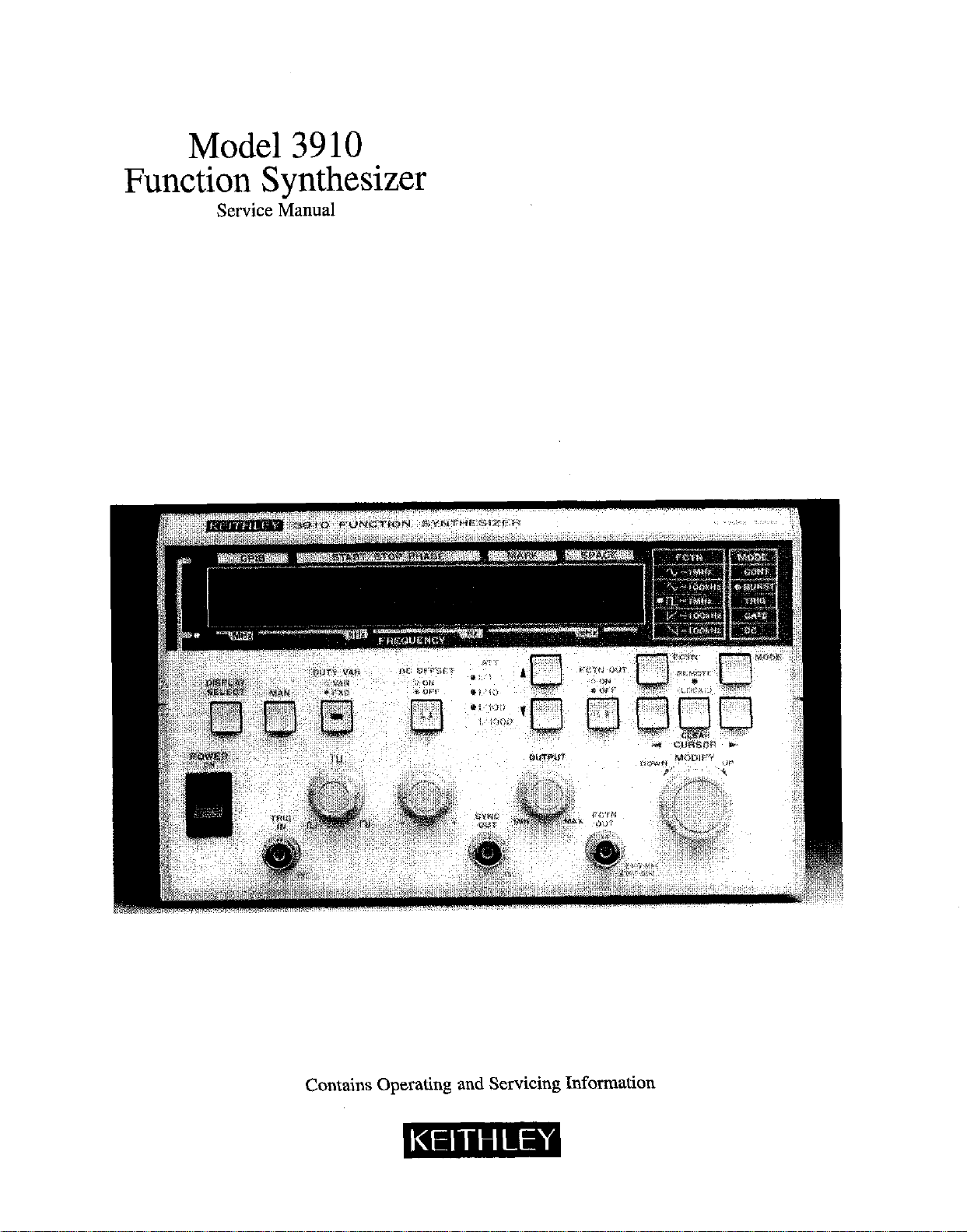
Model 3910
Function Synthesizer
Service Manual
Contains Operating and Servicing Information
WARRANTY
Kcithley Instruments, Inc. warrants this product to be free from defects in material and workmanship for a period of 1 year from date of
shipment.
Kcithley Instruments, Inc. warrants the following items for 90 days from the date of shipment: probes, cables, rechargeable batlcrics,
diskettes. and documentation.
During the warranty period, we will, at our option, either repair or replace any product that proves to be defective.
To exercise this warranty, write or call your local Keithley representative, 01‘ contact Keithley hcadquaxters in Cleveland, Ohio. You will
bc given prompt assistance and return instructions. Send the product, transportation prepaid, to the indicated service facility. Repairs
will bc made and the product returned, transportation prepaid. Repaired or replaced products are warranted for the balance of the original warranty period, or at least 90 days.
LIMITATION OF WARRANN
This warranty does not apply to defects resulting from product modification without Keithley’s express written consent, or misuse of
any product or part. This wzuranty also does not apply to fuses, software, non-rechargeable batteries, damage from battery leakage, or
problems arising from normal wear or failure to follow instructions.
THIS WARRANTY IS IN LIEU OF ALL OTHER WARRANTIES, EXPRESSED OR IMPLIED, INCLUDING ANY IMPLIED
WARRANTY OF MERCHANTABILITY OR FITNESS FOR A PARTICULAR USE. THE REMEDIES PROVIDED HEREIN ARE
BUYER’S SOLE AND EXCLUSIVE REMEDIES.
NEITHER KEITHLEY INSTRUMENTS, INC. NOR ANY OF ITS EMPLOYEES SHALL BE LIABLE FOR ANY DIRECT, INDIRECT, SPECIAL, INCIDENTAL OR CONSEQUENTIAL DAMAGES ARISING OUT OF THE USE OF ITS INSTRUMENTS AND
SOFTWARE EVEN IF KEITHLEY INSTRUMENTS, INC., HAS BEEN ADVISED IN ADVANCE OF THE POSSIBILITY OF
SUCH DAMAGES. SUCH EXCLUDED DAMAGES SHALL INCLUDE, BUT ARE NOT LIMITED TO: COSTS OF REMOVAL
AND INSTALLATION, LOSSES SUSTAINED AS THE RESULT OF INJURY TO ANY PERSON, OR DAMAGE TO PROPERTY.
Model 3910 Function Synthesizer
Service Manual
8 1991, Keithley Instruments, Inc.
Test Instrumentation Group
All rights reserved.
Cleveland, Ohio, U.S.A.
October 1991, First Printing
Document Number: 3910-902-01 Rev. A
Manual Print History
The print history shown below lists the printing dates of all Revisions and Addenda created for this manual. The Revision
Level letter increases alphabetically as the manual undergoes subsequent updates. Addenda, which are released between Revisions, contain important change information that the user should incorporate immediately into the manual. Addenda are numbered sequentially. When a new Revision is created. all Addenda associated with the previous Revision of the manual are
incorporated into the new Revision of the manual. Each new Revision includes a revised copy of this print history page.
Revision A (oc.c”me”, Number 39 10.902-01) ,....,,,.,....,..................................................................... October ,991
Safety Precautions
The following safety precautions should be observed before
using this product and any associated instrumentation. Although some instruments and accessories would normally be
used with non-hazardous voltages, there are situations where
hazardous conditions may be present.
This product is intended for use by qualified personnel who
recognize shock hazards and are familiar with the safety precautions required to avoid possible injury. Read the operating
information carefully before using the product.
Exercise extreme caution when a shock hazard is present. Lethal voltage may be present on cable connector jacks or test
fixtures. The American National Standards Institute (ANSI)
states that a shock hazard exists when voltage levels greater
than 30V RMS, 42.4V peak, or 60VDC are present. A good
safety practice is to expect that hazardous voltage is present
in any unknown circuit before measuring.
Before operating an instrument, make sum the line cord is
connected to a properly grounded power receptacle. Inspect
the connecting cables, test leads, and jumpers for possible
wear, cracks, or breaks before each use.
For maximum safety, do not touch the product, test cables, or
any other instruments while power is applied to the circuit
under test. ALWAYS renwve power from the entire test system and discharge any capacitors before: connecting or disconnecting cables or jumpers, installing or removing
switching cards, or making internal changes, such as installing or removing jumpers.
Do not touch any object that could provide a current path to
the common side of the circuit under test or power line
(earth) ground. Always make measurements with dry hands
while standing on a dry, insulated surface capable of withstanding the voltage being measured.
Do not exceed the maximum signal levels of the instruments
and accessories, as defined in the specifications and operating
information, and as shown on the instrument or test fixture
rear panel, or switching card.
Do not connect switching cards directly to unlimited power
circuits. They are intended to be used with impedance limited sources. NEVER connect switching cards directly to AC
main. When connecting sources to switching cards, install
protective devices to limit fault current and voltage to the
card.
When fuses are used in a product, replace with ~arne type and
rating for continued protection against fire hazard.
Chassis connections must only be used as shield connections
for measuring circuits, NOT as safety earth ground connections.
If you are using a test fixture, keep the lid closed while power
is applied to the device under test. Safe operation requires the
use of a lid interlock.
If a @screw is present cm the test fixture, connect it to safety
earth ground using #18 AWG or larger wire.
‘Ihef y bl B m o on an instrument or accessory indicates that
IOOOV or more may be present on the terminals. Refer to the
product manual for detailed operating information.
Instrumentation and accessories should not be connected to
humans.
Maintenance should be performed by qualified service personnel. Before performing any maintenance, disconnect the
line cord and all teat cables.

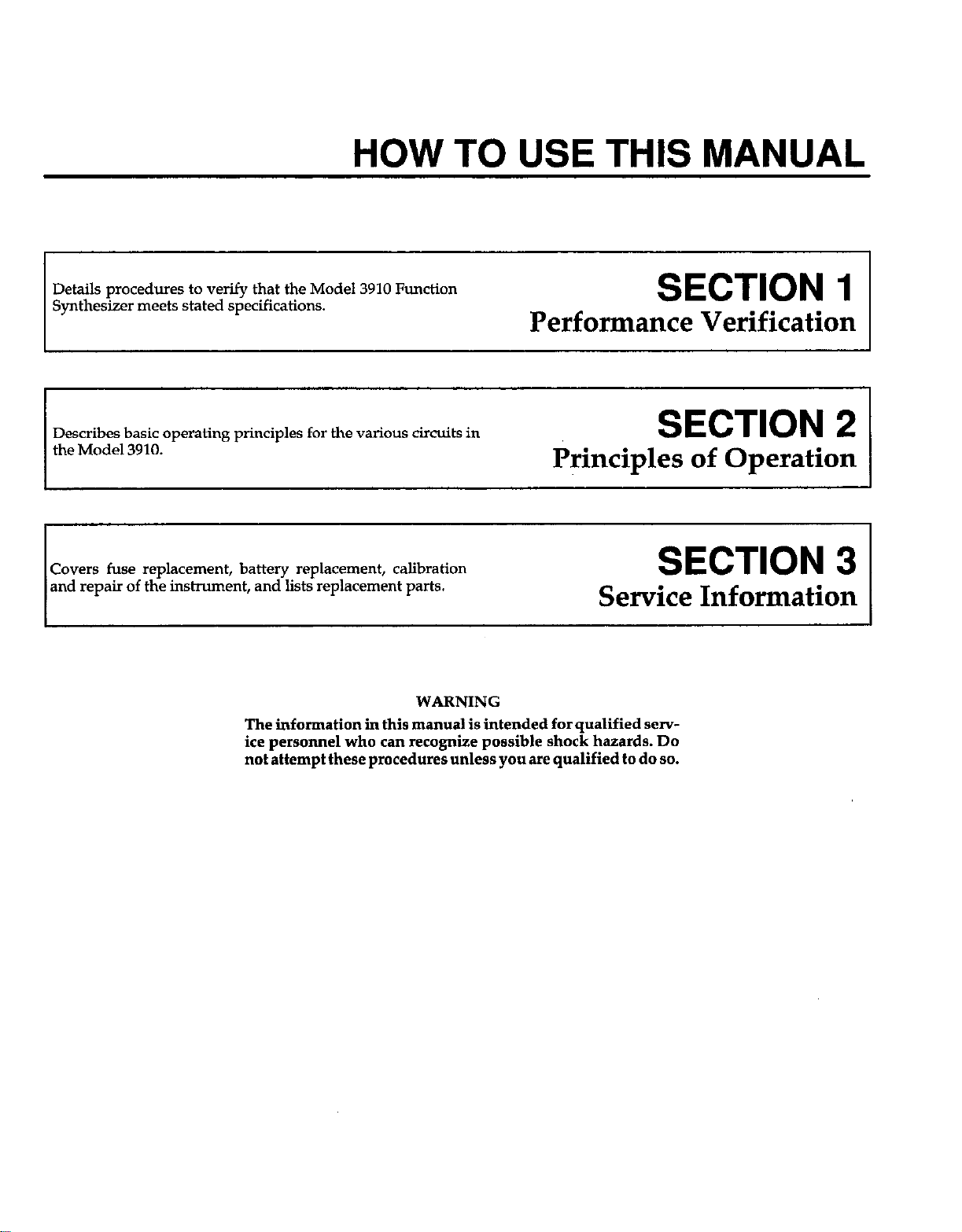
HOW TO USE THIS MANUAL
Details procedures to verify that the Model 3910 Function
Synthesizer
Describes basic operating principles for the various circuits in
the Model 3910.
Covers fuse replacement, battery replacement, calibration
and repair of the instrument, and lists replacement parts.
meets stated
specifications.
WARNING
The information in this manual is intended for qualified service personnel who can recognize possible shock hazards. Do
not attempt these procedures unless you are qualified to do 80.
SECTION 1
Performance Verification
SECTION 2
Principles of Operation
SECTION 3
Service Information


Table of Contents
SECTION 1 - Performance Verification
1.1
1.2
1.3
1.4
1.5
1.6
1.7
1.7.1
1.7.2
1.7.3
1.7.4
1.7.5
INTRODUCTION
ENVIRONMENTAL CONDITIONS ...
INITIAL CONDlTIONS
LINEPOWER
RECOMMENDED TEST EQUIPMBNT .
VERIFICATION LIMITS
VERIFICATION PROCEDURES
Frequency Accuracy
Maximum Output Amplitude
DCOffset
FrequencyResponse..
Total Harmonic Distortion
.................
............
....................
............
......
.............
.............................
............................................
..................................
...............................
SECTION 2 - Principles of Operation
2.1
2.2
2.3
2.3.1
2.3.2
2.3.3
2.3.4
2.3.5
2.3.6
INTRODUCTION
BLOCK DIAGRAM
CIRCUITOPERATION
ControlSection
Display and Keyboard Section
Synthesizer
AnaIogSection
PowerSupply
GPIB Interface.
.................................
...............................
.............................
.................................
......................
....................................
.................................
..................................
.................................
......................
......................
......................
.......................
......................
......................
......................
. . . . .
1-l
1-l
1-l
1-l
l-1
1-z.
l-2
l-2
l-3
l-4
l-4
l-6
2-l
2-l
.
2-l
2-l
2-l
2-l
2-l
2-l
2-2
SECTION 3 - Service Information
3.1
3.2
3.3
3.4
3.4.1
3.4.2
3.4.3
3.4.4
3.4.5
3.4.6
3.4.7
3.4.8
3.4.9
3.4.10
INTRODUCTION
LINE FLJSE REPLACEMENT
BAWRY RBPLACEMENT
CALIBRATION
EnvironmentaI Conditions
Initial Conditions
LinePower
Recommended Calibration Equipment
Cover Removal
Calibration Adjustment Locations
DC Offset Calibration
Amplitude Calibration
Square Wave Duty Cycle Calibration
Cover Replacement
.............................
.....................
..............................
...........................
................................
.............................
........................
.......................
..........................
....................
....................
...............
.............
...........
3-l
3-1
3-2
. . 3-2
. . . . 3-3
.
..,.. 3-3
. . . . .
. . . 3-6
3-3
3-3
3-3
3-4
3-4
3-8
. . 3-8
3.5
3.5.1
3.5.2
3.6
3.6.1
3.6.2
3.7
3.7.1
3.7.2
3.8
3.8.1
3.8.2
FCTN OUT JUMPERS
Waveform Output On/Off Selection
FCTN OUT Open/Short Selection
GI’IB INTERFACE INSTALLATlON
Installation Precautions .............................
Board Installation .................................
REPAIR ..........................................
Factory Service ...................................
BoardRemoval
REPLACEABLE PARTS ..............................
PartsList .......................................
OrderingParts
...............................
...................
.....................
.....................
...................................
...................................
........
........
........
........
........
........
........
........
........
........
........
3-8
3-8
3-9
3-9
3-9
3-9
3-12
3-12
3-12
3-15
3-15
3-15
APPENDICES
A TypicalData.................................................................. A-l
B Model 3910 and 3910/11 Specifications
B-l
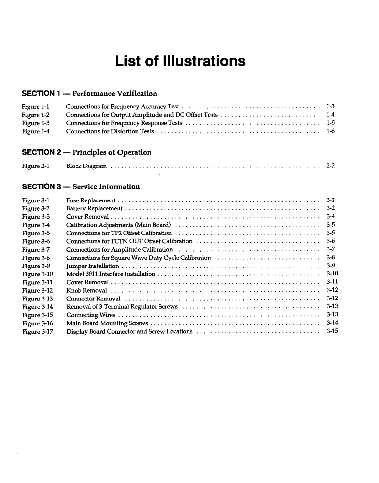
List of Illustrations
SECTION 1
Figure l-l
Figure 1-2
Figure l-3
Figure 14
- Performance Verification
Connections for Frequency Accuracy Test .
Connections for Output Amplitude and DC Offset Tests
Connections for Frequency Response Tests . . . .
Connections for Distortion Tests . . . .
SECTION 2 - Principles of Operation
Figure 2-l
Block Diagram
,..............................
SECTION 3 - Service Information
Figure 3-l
Figure 3-2
Figure 3-3
Figure 3-4
Figure 3-5
Figure 3-6
Figure 3-7
Figure 3-S
Figure 3-9
Figure 3-10
Figure 3-l 1
Figure 3-12
Figure 3-13
Figure 3-14
Figure 3-15
Figure 3-16
Figure 3-17
Fuse Replacement ...........................
Battery Replacement .........................
CoverRemoval .............................
Calibration Adjustments (Main Board)
Connsctions for TP2 Offset Calibration
Connections for FCI’N OUT Offset Calibration
Connections for Amplitude Calibration
Connections for Square Wave Duty Cycle Calibration
Jumper Installation ..........................
Model 3911 Interface Installation
Cover Removal ........................
KnobRemoval ........................
Connector Removal ....................
Removal of 3-Terminal Regulator Screws
Connecting Wires ......................
Main Board Mounting Screws .............
Display Board Connector and Screw Locations
...........
...........
...........
................
....
.....
..........................
..........................
..........................
...................
..........................
..........................
..........................
.................
................. 14
.................
.................
. . . . . . . . . . . . . . . . . 2-2
.......................
.......................
.......................
.......................
......................
......................
......................
....................
....................
.......
l-3
l-5
l-6
3-l
3-2
34
3-5
3-5
3-6
3-7
3-8
3-9
3-10
3-11
3-12
3-12
3-13
3-13
3-14
3-15

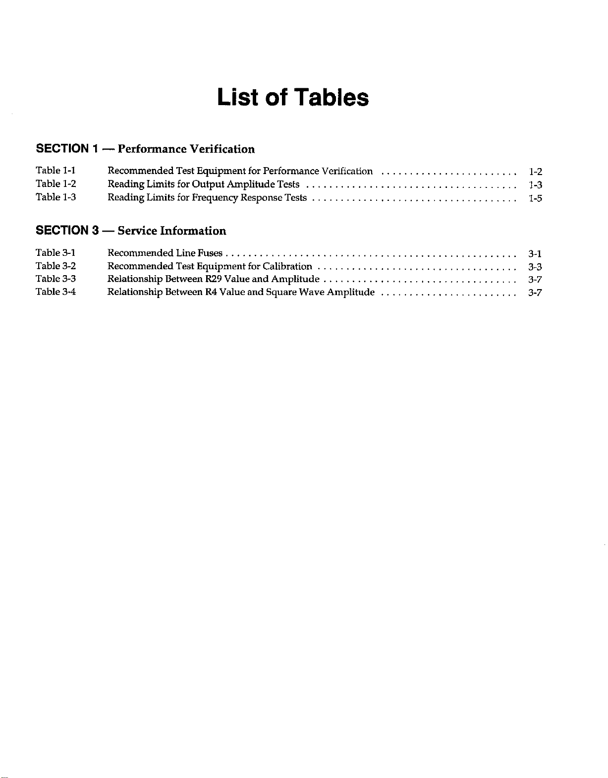
List of Tables
SECTION 1 - Performance Verification
Table l-l Recommended Test Equipment for Performance Verification
Table l-2 Reading Limits for Output Amplitude Tests
Table l-3 Reading Limits for Frequency Response Tests
.................................
................................
SECTION 3 - Service Information
Table 3-l
Table 3-2
Table 3-3
Table 3-4
RecommendedLineFuses
Recommended Test Equipment for Calibration
Relationship Between R29 Value and Amplitude
Relationship Between R4 Value and Square Wave Amplitude
...............................................
...............................
..............................
....................
....................
l-2
l-3
l-5
3-l
3-3
3-7
3-7

SECTION 1
Performance Verification
1.1 INTRODUCTION
This section covers procedures to verify accuracy of the
Model 3910. Verification can be performed when the in-
shument is first received to verify that the Model 3910
meets its stated accuracy specifications, and it can also be
performed following calibration, if desired. If the lnshument fails to meet stated specifications, refer to the calibration and repair information in Section 3 unless the
unit is still under warranty (less than one year from the
date of shipment).
NOTE
Inshuments still under warranty should be
rehuned to the factory for calibration or repair.
1.2 ENVIRONMENTAL CONDITIONS
All measurements should be made at 18-28°C (65-82°F)
and at less than 70% relative humidity.
1.3 INITIAL CONDITIONS
The Model 3910 and the test equipment should be turned
on and allowed to warm up for one hour before making
test measurements. If the instrument has been subjected
to extreme temperature or humidity, allow additional
time for stabilization. Typically, it take one additional
hour to stabilize an instrument that is 10°C outside the allowed temperature range.
1.4 LINE POWER
Before testing, be sure the rear panel line voltage is set to
the correct operating voltage. The Model 3910 should be
tested while operating at a line voltage within flO% of
the line voltage switch setting and at a line frequency
from 48Hz to 62Hz.
1.5 RECOMMENDED TEST EQUIPMENT
Table 1-l summarizes recommended equipment for the
verification procedures. Similar equipment may be used
as long as corresponding specifications are comparable.
l-l
 Loading...