

Page 1

x
370B
Programmable Curve Tracer
ZZZ
Service Manual
*P070A84250*
070-A842-50
Page 2

Page 3

xx
370B
Programmable Curve Tracer
ZZZ
Service Manual
Revision C
Warning
The servicing instructions are for use by qualified personnel only. To
avoid personal injury, do not perform any servicing unless you are
qualified to do so. R efer to all safety summaries prior to performing
service.
www.tektronix.com
070-A842-50
Page 4

Copyright © Tektronix. All rights reserved. Licensed software products are owned by Tektronix or its subsidiaries or suppliers, and are
protected by na
tional copyright laws and international treaty provisions.
Tektronix pro
previously published material. Specifications and price change privileges reserved.
TEKTRONIX and TEK are registered trademarks of Tektronix, Inc.
ducts are covered by U.S. and foreign patents, issued and pending. Information in this publication supersedes that in all
Contacting Tektronix
Tektronix, Inc.
14200 SW Karl Braun Drive
P.O. Box 500
Beaverton, OR 97077
USA
For product information, sales, service, and technical support:
In North America, call 1-800-833-9200.
Worldwide, visit www.tektronix.com to find contacts in your area.
Page 5

Warranty 2
Tektronix warrants that this product will be free from defects in materials and workmanship for a period of one (1) year
from the date of shipment. If any such product proves defective during this warranty period, Tektronix, at its option, either
will repair the defective product without charge for parts and labor, or will provide a replacement i n exchange for the
defective product. Parts, modules and replacement products used by Tektronix for warranty work may be new or
reconditioned to like new performance. All replaced parts, m odules and products become the property of Tektronix.
In order to obtai n service under this warranty, Customer must notify Tektronix of the defect before the expiration of the
warranty period and make suitable arrangements for the performance of service. Customer shall be responsible for
packaging and shipping the defective product to the service center designated by Tektronix, with shipping charges prepaid.
Tektronix shall pay for the return of the product to Customer if the shipment is to a location within the country in which the
Tektronix service center is located. Customer shall be responsible for paying all shipping charges, duties, taxes, and any
other charges for products returned to any other locations.
This warranty shall not apply to any defect, failure or damage caused by improper use or improper or inadequate
maintenance and care. Tektronix shall not be obligated to furni sh servi ce under this warranty a) to repai r damage resulting
from attempts by personnel other than Tektronix representatives to install, repair or service the product; b) to repair
damage resulting from improper use or c onne ction to incompatible equipment; c) to repair any dam age or malfunction
caused by the use of non-Tektronix supplies; or d) to service a product that has been modified or integrated with other
products when the effect of such modification or i ntegration increases the time or difficulty of servicing the product.
THIS W ARRANTY IS GIVEN BY TEKTRONIX IN LIEU OF ANY OTHER W ARRANTIES, EXPRESS OR
IMPLIED. TEKTRONIX AND ITS VENDORS DISCLAIM ANY IMPLIED WARRANTIES OF
MERCHANTABILITY OR FITNESS FOR A PARTICULAR PURPOSE. TEKTRONIX’ RESPONSIBILITY TO
REPAIR OR REPLACE DEFECTIVE PRODUCTS IS THE SOLE AND EXCLUSIVE REMEDY PROVIDED TO
THE CUSTOMER FOR BREACH OF THIS WARRANTY. TEKTRONIX AND ITS VENDORS WILL NOT BE
LIABLE FOR ANY INDIRECT, SPECIAL, INCIDENT AL, OR CONSEQUENTIAL DAMAGES IRRESPECTIVE
OF WHETHER TEKTRONIX OR THE VENDOR HAS ADVANCE NOTICE OF THE POSSIBILITY OF SUCH
DAMAGES.
Page 6

Page 7

Table of Contents
Specifications
Operating Information
General Safety Summary vii...................................
Service Safety Summary ix....................................
Preface xi...................................................
Introduction xv..............................................
Product Overview 1--1.........................................
Specifications 1--3.............................................
Performance Conditions 1--3...........................................
Electrical Specifications 1--4...........................................
Mechanical Specifications 1--17.........................................
Functional Specifications 1--18.........................................
Environmental Specifications 1--19......................................
GPIB Interface 1--22..................................................
Operating Information 2--1.....................................
Installation 2--1.....................................................
Kelvin Sense 2--5....................................................
Rackmounting Information 2--7........................................
Repacking for shipment 2--13...........................................
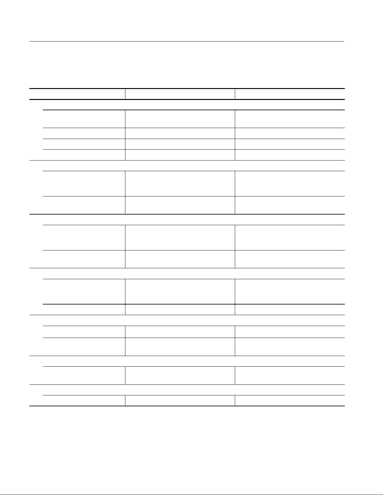
Theory of Operation
Theory of Operation 3--1.......................................
Block Diagram Description 3--1........................................
Circuit Operation 3--6................................................
Maintenance
Maintenance 4--1..............................................
Preventive Maintenance 4--1...........................................
Corrective Maintenance 4 --4...........................................
Performance Verification
Performance Verification 5--1...................................
Using Procedure 5--3.................................................
Power Supply 5--12...................................................
CRT 5--17...........................................................
Display 5--26........................................................
Horizontal 5--44......................................................
Vertical 5--54........................................................
Step Generator 5--71..................................................
Collector Supply 5--104.................................................
AUX Supply 5--119....................................................
370B Service Manual i
Page 8

Table of Contents
Instrument Options
Electrical Parts List
Diagrams
Mechanical Parts List
Configuration 5--122...................................................
Key Operation and Floppy Disk Drive 5--129................................
Options 6--1........................................................
Accessories 6--2.....................................................
Replaceable Electrical Parts 7--1.................................
Parts Ordering Information 7 --1.........................................
Using the Replaceable Electrical Parts List 7--2............................
Diagrams 8--1.................................................
Mechanical Parts List 9--1......................................
Parts Ordering Information 9 --1.........................................
Using the Replaceable Parts List 9--2....................................
ii 370B Service Manual
Page 9

List of Figures
Table of Contents
Figure 2--1: Example of Kelvin sense connection 2--6................
Figure 2--2: Location of the Rackmount Latch Release 2--7...........
Figure 2--3: Rackmount hole spacing 2--8..........................
Figure 2--4: Rackmounting Length and Clearance 2--8..............
Figure 2--5: Rackmounting Hardware 2--9.........................
Figure 2--6: Mounting Stationary Rackmount Sections 2--10...........
Figure 2--7: Cabinet-to-Rackmount Conversion 2--12.................
Figure 3--1: 370B Block Diagram 3--3.............................
Figure 5--1: Diagnostic test pattern display 5--32.....................
Figure 5--2: Looping compensation display 5--40....................
Figure 5--3: Checking Collector high current range 5--67..............
Figure 5--4: Examining and Adjusting for Step Generator Offset 5--73..
Figure 5--5: Adjusting for Current Amplifier Bias 5--75...............
Figure 5--6: Checking for Maximum OFFSET of 200 mA Range 5--83..
Figure 5--7: Checking for Maximum Current Output of 100 mA
and 200 mA range 5--96......................................
Figure 5--8: Adjusting for Collector Supply Amplifier Offset 5--105......
Figure 5--9: Examining for DC and LEAKAGE operation 5--113........
Figure 8--1: 370B circuit board locator 8--1........................
Figure 9--1: Cabinet, Rear 9--9...................................
Figure 9--2: Display, Front 9--10..................................
Figure 9--3: Chassis Circuit Boards 9--17...........................
Figure 9--4: Power Supply 9--18...................................
Figure 9--5: Front Panel: L-O-R 9--27..............................
Figure 9--6: LV, L-O-R, Looping Circuit Boards 9--28................
Figure 9--7: FDD, Config. Relay, Sense Circuit Boards 9--35...........
Figure 9--8: Accessories 9--36.....................................
370B Service Manual iii
Page 10

Table of Contents
List of Tables
Table 1--1: Collector Supply 1 -- 4.................................
Table 1--2: Step Generator 1--7..................................
Table 1--3: AUX Supply 1--10....................................
Table 1--4: Non-store Vertical Deflection System 1--10................
Table 1--5: Digital Storage Vertical Acquisition 1--12.................
Table 1--6: Non-store Horizontal Deflection System 1--13.............
Table 1--7: Digital Storage Horizontal Acquisition 1--14..............
Table 1--8: CRT and Readout 1--15...............................
Table 1--9: Adapter Connectors 1--16..............................
Table 1--10: Power Supply 1--17..................................
Table 1--11: Surge Current 1 -- 17..................................
T able 1--12: Mechanical Specification 1--17.........................
Table 1--13: Digital Storage Acquisition Mode 1--18.................
Table 1--14: Text Display 1--18...................................
Table 1--15: Environmental Specification 1--19......................
Table 1--16: Certifications and Compliances 1--20...................
Table 1--17: Installation category and Pollution degree Descriptions 1--21
Table 1--18: GPIB Interface 1--22.................................
Table 2--1: Line voltage ranges 2--1...............................
Table 2--2: Power Cord Color Conductor Identification 2--2..........
Table 2--3: Power cord identification 2--3.........................
Table 4--1: Power-on System Error Messages 4--24..................
Table 4--2: Front Panel Control Identification 4--25..................
Table 5--1: Performance Check and Adjustment Procedure Options 5--2
T able 5--2: Performance Check Summary 5--4.....................
Table 5--3: Test Equipment 5--10.................................
Table 5--4: Voltage Regulation and Ripple 5--13.....................
Table 5--5: Base/Emitter Voltage Accuracy 5--48.....................
T able 5--6: Collector Voltage Accuracy 5--50........................
Table 5--7: Displayed Horizontal Noise 5--53........................
T able 5--8: Emitter Current Accuracy 5--61........................
T able 5--9: Collector Current Accuracy 5--63.......................
T able 5--10: Collector High Current Accuracy 5--67.................
iv 370B Service Manual
Page 11

Table of Contents
Table 5--11: Displayed Vertical Collector Noise in CONFIGURATION
BASE to COLLECTOR SUPPLY mode 5--70...................
Table 5--12: OFFSET Voltage 5--79...............................
Table 5--13: OFFSET Voltage 5--80...............................
Table 5--14: OFFSET Current 5--82...............................
Table 5--15: Max Peak Volts 5--108.................................
Table 5--16: Max Peak Volts 5--109.................................
Table 5--17: Maximum Peak Currents 5--111........................
Table 5--18: Auxiliary Supply Accuracy 5--120.......................
T able 6--1: Standard accessories 6--2.............................
Table 6--2: Optional accessories 6--2..............................
T able 6--3: Recommended accessories 6--3.........................
370B Service Manual v
Page 12

Table of Contents
vi 370B Service Manual
Page 13

General Safety Summary
Review the following safety precautions to avoid injury and prevent damage to
this product or any products connected to it. To avoid potential hazards, use this
product only as specified.
Only qualified personnel should perform service procedures.
ToAvoidFireor
Personal Injury
Use Proper Power Cord. Use only the power cord specified for this product and
certified for the country of use.
Use Proper Voltage Setting. Before applying power, ensure that the line selector is
in the proper position for the power source being used.
Connect and Disconnect Pr operly. Do not connect or disconnect probes or test
leads while they are connected to a voltage source.
Ground the Product. This product is grounded through the grounding conductor
of the power cord. To avoid electric shock, the grounding conductor must be
connected to earth ground. Before making connections to the input or output
terminals of the product, ensure that the product is properly grounded.
Observe All Terminal Rat ings. To avoid fire or shock hazard, observe all ratings
and markings on the product. Consult the product manual for further ratings
information before making connections to the product.
The common terminal is at ground potential. Do not connect the common
terminal to elevated voltages.
Do not apply a potential to any terminal, including the common terminal, that
exceeds the maximum rating of that terminal.
Do Not Operate Without Covers. Do not operate this product with covers or panels
removed.
Use Proper Fuse. Use only the fuse type and rating specified for this product.
Avoid Exposed Circuitry. Do not touch exposed connections and components
when power is present.
Do Not Operate With Suspected Failures. If you suspect there is damage to this
product, have it inspected by qualified service personnel.
Do Not Operate in Wet/Damp Conditions.
Do Not Operate in an Explosive Atmosphere.
Keep Product Surfaces Clean and Dry.
Provide Proper Ventilation. Refer to the manual’s installation instructions for
details on installing the product so it has proper ventilation.
370B Service Manual vii
Page 14
General Safety Summary
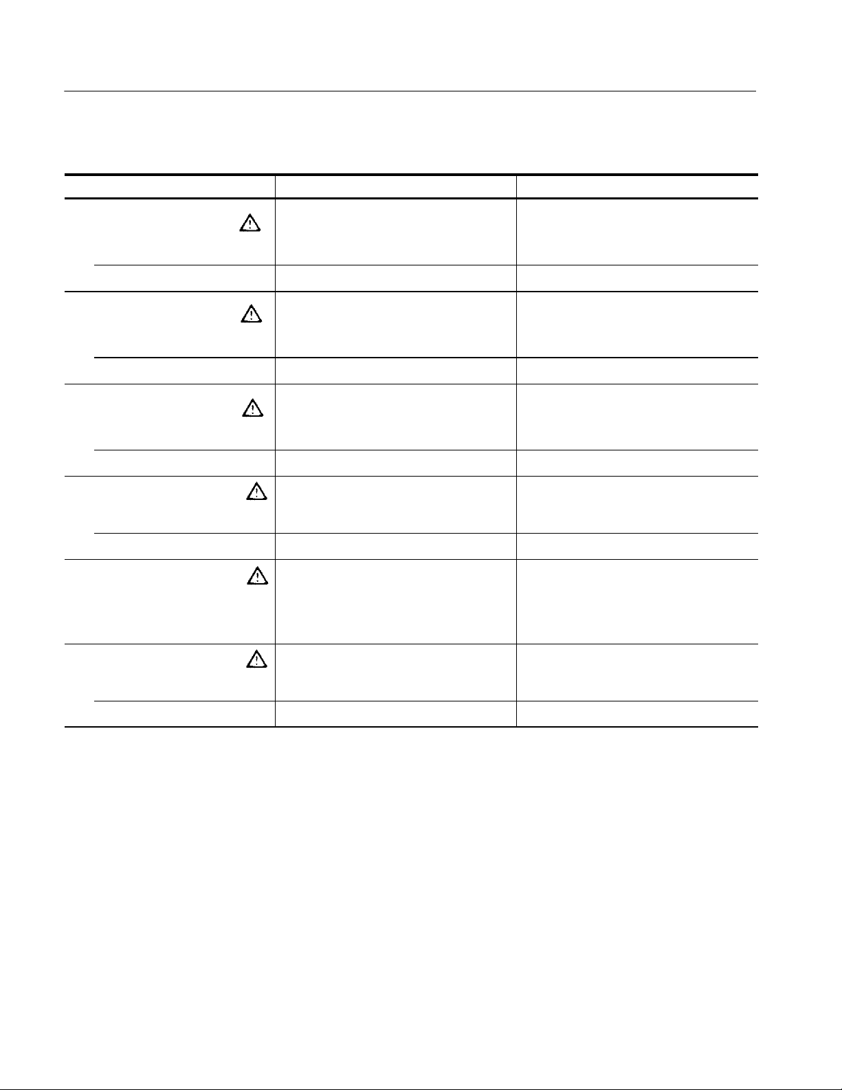
Symbols and Terms
Terms in this Manual. These terms may appear in this manual:
WARNING. Warning statements identify conditions or practices that could result
in injury or loss of life.
CAUTION. Caution statements identify conditions or practices that could result in
damage to this product or other property.
Terms on the Product. These terms may appear on the product:
DANGER indicates an injury hazard immediately accessible as you read the
marking.
WARNING indicates an injury hazard not immediately accessible as you read the
marking.
CAUTION indicates a hazard to property including the product.
Symbols on the Product. The following symbols may appear on the product:
WARNING
High Voltage
Protective Ground
(Earth) Terminal
CAUTION
Refer to Manual
Double
Insulated
viii 370B Service Manual
Page 15

Service Safety Summary
Only qualified personnel should perform service procedures. Read this Service
Safety Summary and the General Safety Summary before performing any service
procedures.
Do Not Service Alone. Do not perform internal service or adjustments of this
product unless another person capable of rendering first aid and resuscitation is
present.
Disconnect Power. To avoid electric shock, disconnect the mains power by means
of the power cord or, if provided, the power switch.
Use Care When Servicing With Power On. Dangerous voltages or currents may
exist in this product. Disconnect power, remove battery (if applicable), and
disconnect test leads before removing protective panels, soldering, or replacing
components.
To avoid electric shock, do not touch exposed connections.
370B Service Manual
ix
Page 16

Service Safety Summary
370B Service Manual
x
Page 17

Preface
Manual Structure
This is the service manual for the 370B Programmable Curve Tracer. The manual
contains information needed to service the 370B to the module level.
This manual is divided into sections, such as Specifications and Theory of
Operation. Further, some sections are divided into subsections, such as Product
Description and Removal and Installation Procedures.
Sections containing procedures also contain introductions to those procedures.
Be sure to read these introductions because they provide information needed to
do the service correctly and efficiently. The following contains a brief description
of each manual section.
H Specifications contains a description of the 370B Programmable Curve
Tracer and the characteristics that apply to it.
H Operating Information includes general information and operating
instructions.
H Theory of Operation contains circuit descriptions that support service to the
module level.
H Performance Verification contains procedures for confirming that the 370B
Programmable Curve Tracer functions properly and meets warranted limits.
H Adjustment Procedures contains a collection of procedures for adjusting the
370B Programmable Curve Tracer to meet warranted limits.
H Maintenance contains information and procedures for performing preventive
and corrective maintenance of the 370B Programmable Curve Tracer. These
instructions include cleaning, module removal and installation, and fault
isolation to the module.
H Options contains information on servicing factory-installed options.
H Electrical Parts List contains a statement referring you to Mechanical Parts
List, where both electrical and mechanical modules are listed.
H Diagrams contains an block diagram and an interconnection diagram.
H Mechanical Parts List includes a table of all replaceable modules, their
descriptions, and their Tektronix part numbers.
370B Service Manual xi
Page 18

Preface
Manual Conventions
This manual uses certain conventions that you should become familiar with.
Some sections of the manual contain procedures for you to perform. To keep
those instructions clear and consistent, this manual uses the following conventions:
H Names of front panel controls appear in the same case (initial capitals, all
uppercase, etc.) in the manual as is used on the 370B Programmable Curve
Tracer front panel. Front panel names are all upper-case letters; for example,
REF, SAVE, VIEW etc.
H Instruction steps are numbered unless there is only one step.
Modules
Safety
Throughout this manual, any replaceable component, assembly, or part of the
370B Programmable Curve Tracer is referred to generically as a module. In
general, a module is an assembly (like a circuit board), rather than a component
(like a resistor or an integrated circuit). Sometimes a single component is a
module; for example, the chassis of the 370B Programmable Curve Tracer is a
module.
Symbols and terms related to safety appear in the Safety Summary near the
beginning of this manual.
Finding Other Information
Other documentation for the 370B includes:
H The 370B Programmable Curve Tracer User Manual contains a tutorial to
quickly describe how to operate the370B Programmable Curve Tracer. It also
includes an in-depth discussion on how to more completely use the 370B
Programmable Curve Tracer features.
xii 370B Service Manual
Page 19

Preface
370B Service Manual xiii
Page 20

Preface
xiv 370B Service Manual
Page 21

Introduction
This manual contains information needed to properly service the 370B Programmable Curve Tracer as well as general information critical to safe and effective
servicing.
To prevent personal injury or damage to the analyzer, consider the following
before attempting service:
H The procedures in this manual should be performed only by a qualified
service person
H Read the General Safety Summary and the Service Safety Summary,
beginning on page vii
H Read Preparation for Use in section 2, Operating Information
When using this manual for servicing, be sure to follow all warnings, cautions,
and notes.
Performance Check Interval
Strategy for Servicing
Generally, the performance check described in section 4,
Performance Verification, should be done every 12 months. In addition,
performance check is recommended after module replacement.
If the analyzer does not meet performance criteria, repair is necessary.
Throughout this manual, the term, module, refers to any field-replaceable
component, assembly, or part of the analyzer.
This manual contains all the information needed for periodic maintenance of the
370B Programmable Curve Tracer (Examples of such information are procedures
for checking performance.)
Further, it contains all information for corrective maintenance down to the
module level. To isolate a failure to a module, use the fault isolation procedures
found in Troubleshooting, part of section 6, Maintenance. To remove and replace
any failed module, follow the instructions in Removal and Installation
Procedures, also part of section 6. After isolating a faulty module, replace it with
a fully-tested module obtained from the factory. Section 9, Mechanical Parts
List, contains part number and ordering information for all replaceable modules.
370B Service Manual xv
Page 22

Introduction
Tektronix Service Offerings
Tektronix provides service to cover repair under warranty as well as other
services that may provide a cost-effective answer to your service needs.
Whether providing warranty repair service or any of the other services listed
below, Tektronix service technicians are well trained to service the waveform
generator. They have access to the latest information on improvements to the
370B as well as new options.
Warranty Repair Service
Self Service
Tektronix warrants this product for one year from date of purchase. The warranty
appears on the back of the title page in this manual. Tektronix technicians
provide warranty service at most Tektronix service locations. The Tektronix
product catalog lists all worldwide service locations or you can visit our Web site
for service information: www.tektronix.com.
Tektronix supports repair to the module level by providing Module Exchange.
Module Exchange. This service reduces down-time for repair by allowing you to
exchange most modules for re-manufactured ones. Each module comes with a
90-day service warranty.
For More Information. Contact your local Tektronix service center or sales
engineer for more information on any of the repair or adjustment services just
described.
xvi 370B Service Manual
Page 23

Specifications
Page 24

Page 25

Product Overview
The 370B Programmable Curve Tracer is a high-performance, GPIB-programmable digital storage curve tracer that provides static and dynamic semiconductor device testing. This versatile instrument stimulates, measures, and displays
the semiconductor characteristics of a variety of two-, three-, and four-terminal
devices; including bipolar transistors, field effect transistors, silicon-controlled
rectifiers, diodes, thyristors, opto-isolators, wafers, integrated circuits, etc.
A variety of measurements can be performed using either grounded-emitter or
grounded-base configurations.
The side, top, and bottom cabinet panels provide protection to personnel from
operating potentials present within the instrument. In addition, they reduce
radiation of electromagnetic interference from the instrument. The cabinet panels
are held in place by screws and four plastic panel retainers. To remove the
panels, remove the four plastic retainers and three additional securing screws at
the rear of the instrument. Pull each panel back to release the front edge. then lift
the panels away from the instrument. Operate the instrument with the panels in
place to protect the interior from dust, and to maintain cooling airflow.
The collector supply produces AC, rectified AC, or DC voltages ranging from 0
to 2000 volts. This high voltage, combined with a current sensitivity of
100 pA/div, permits extended breakdown measurements of a device under test. A
step generator produces voltage or current steps of either polarity for application
to the base or emitter terminal. The step generator may also be operated in a
pulsed mode to control the power dissipated by the DUT.
370B Service Manual
In addition to conventional curve tracer performance, the 370B Programmable
Curve T racer includes the following features:
H Digital storage capability that allows bright and stable display and useful
cursor measurements. The 370B has a mass storage system consists of
non-volatile IC memory and 3.5-inch floppy disk drive. Up to 64 families of
characteristic curves and front-panel setups can be stored in a floppy disk.
Up to 16 families of characteristic curves and front-panel setups can also be
stored in non-volatile IC memory. The stored characteristic curves can be
recalled for additional analysis and comparison.
H Two extended acquisition modes, called Averaging and Envelope. Averaging
reduces display noise in high sensitivity ranges. Envelope mode displays
only the maximum and minimum vertical or horizontal excursion of each
curve, which is useful for detecting long-term variations such as thermal
drift.
1- 1
Page 26

Product Overview
H Almost all of the 370B front-panel settings can be controlled by GPIB
commands. (Exceptions are those controls intended only for manual
operation, such as INTENSITY, FOCUS, GRAT ILLUM, etc.) Also, curve
data can be sent to or received from an external controller through the GPIB.
H The printer interface permits sending displayed curve data and digital
on-screen readouts to a printer without an external controller.
H Other features include an auxiliary voltage supply, cursor measurement
readout, and diagnostic routines.
1- 2
370B Service Manual
Page 27

Specifications
This section contains the 370B Programmable Curve Tracer specifications. All
specifications are guaranteed unless labeled “typical”. Typical specifications are
provided for your convenience but are not guaranteed.
Performance Conditions
The performance limits in this specification are valid with these conditions:
H The 370B Programmable Curve Tracer must have been calibrated/adjusted at
H The 370B Programmable Curve Tracer must be in an environment with
H The 370B Programmable Curve Tracer must have had a warm-up period of
H The 370B Programmable Curve Tracer must be operating at an ambient
an ambient temperature between +20
temperature, altitude, humidity, and vibration within the operating limits
described in these specifications.
at least 20 minutes.
temperature between +10
_C and +40 _C.
_C and +30 _C.
Warranted characteristics are described in terms of quantifiable performance
limits which are warranted.
370B Service Manual
1- 3
Page 28

Specifications
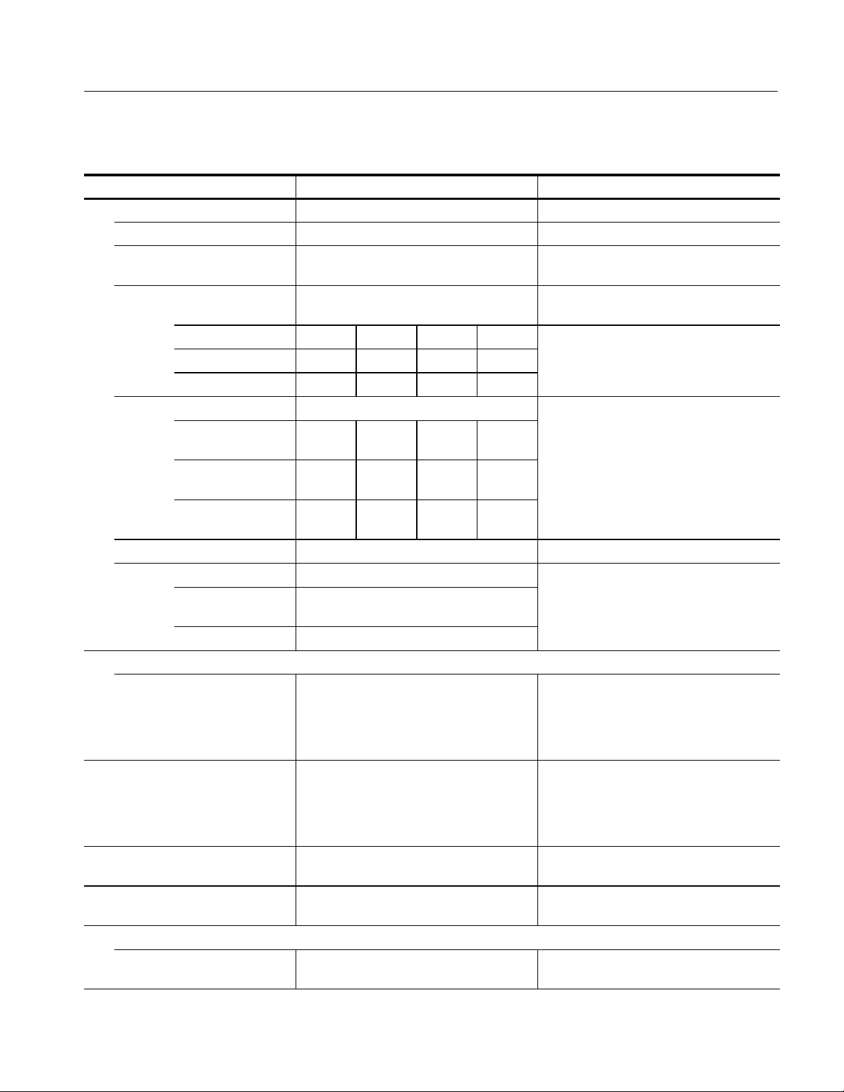
Electrical Specifications
Table 1- 1: Collector Supply
Characteristic Performance Requirement Operating Information
Polarity
+ LEAKAGE Applies positive DC voltage to the collector or
base terminal. Measures emitter current.
Sensitivity is increased 1000 times.
+DC Applies positive DC voltage to the collector or
base terminal. Measures collector or base
current.
+ Applies positive swept voltage to the collector
or base terminal. Measures collector or base
current.
AC Applies line-frequency sine wave to the
collector or base terminal. Measures collector
or base current.
-- Applies negative swept voltage to the
collector or base terminal. Measures collector
or base current.
-- D C Applies negative DC voltage to the collector
or base terminal. Measures collector or base
current.
-- LEAKAGE Applies negative DC voltage to the collector
or base term inal. Measures emitter current.
Sensitivity is increased 1000 times.
DC mode ripple
(no load)
Less than 2% of output voltage. VARIABLE COLLECTOR SUPPLY at 30% or
higher
Less than 0.5% of output voltage. VARIABLE COLLECTOR SUPPLY at 30% or
less
1- 4
370B Service Manual
Page 29
Specifications
availa
c
V*V/(4R)
W
P=VV/(4R)for<220W
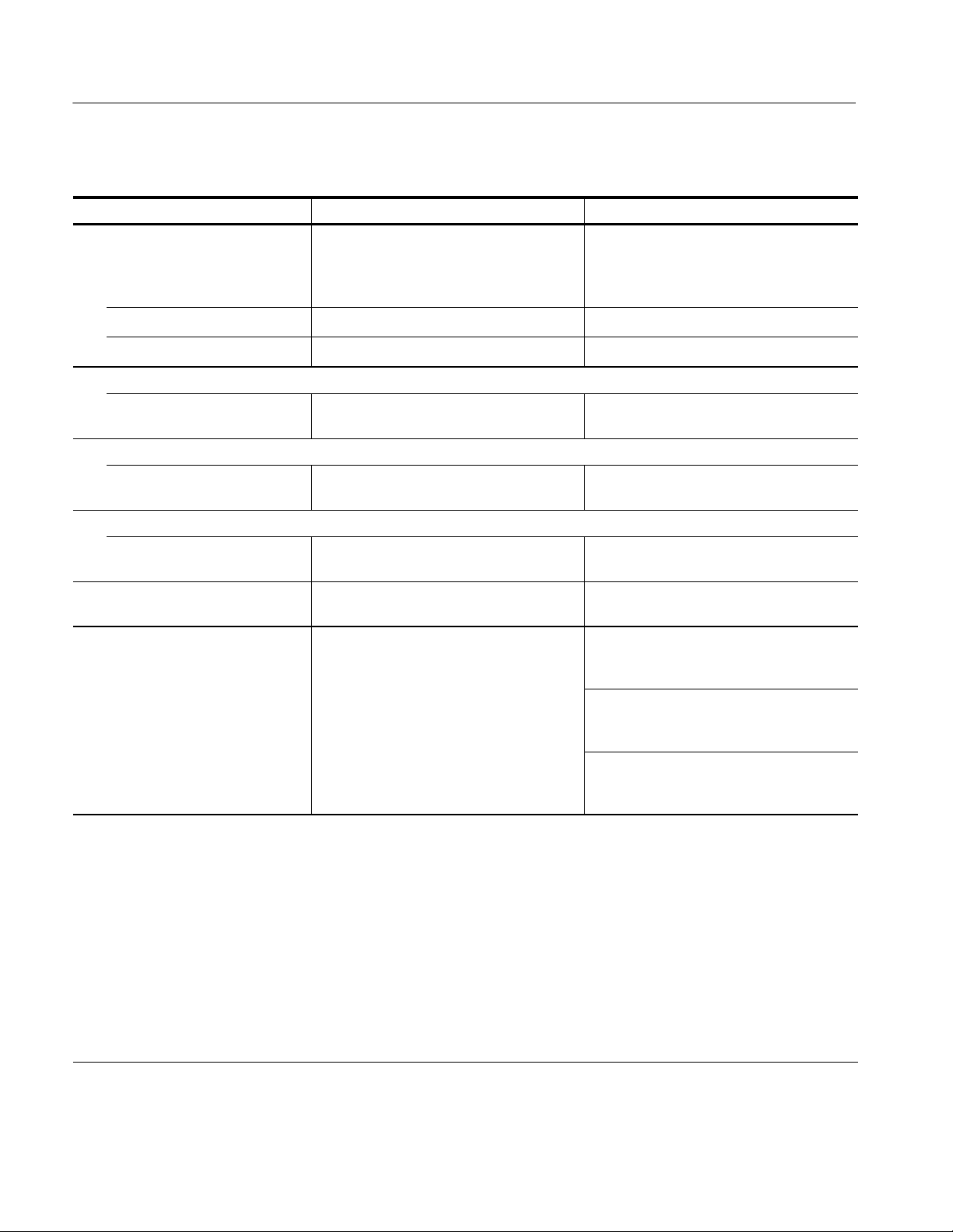
Table 1- 1: Collector Supply (Cont.)
Characteristic Operating InformationPerformance Requirement
Max peak volts
Max peak voltage 16 V, 80 V, 400 V, 2000 V Selected by the MAX PEAK VOLTS buttons.
Voltage accuracy Peak open circuit voltage on all ranges within
+15%, --0%.
Current available In PULSE mode of STEP GENERATOR,
Peak volts 16 V 80 V 400 V 2000 V In PULSE mode of STEP GENERATOR,
Range 10 A 2A 0.4 A 0.05 A
Max peak current 20 A 4A 0.8 A 0.1 A
Series Resistance Available Selection of 0.26 Ω,1.3Ω,6.4Ω,32Ω,
Min/Max resistance
peak volts range
Minimum series
resistance (Ω)
Maximum series
resistance (Ω)
Resistance accuracy Within 5% or 0.2 Ω.
Peak power watts available Derived from nominal peak open-circuit
16, 80 and
400 V range
2000 V range 50 W, 10 W, 2 W, 0.4 W, 0.08 W
16 V 80 V 400 V 2000 V
0.26 6.4 160 20 k
800 20 k 500 k 12.5 M,
220 W, 50 W, 10 W, 2 W, 0.4 W, 0.08 W
At MAX PEAK POWER of 50 W.
available current is two times of DC mode.
blecurrent is two times ofDC mode.
160 Ω, 800 Ω,4kΩ,20kΩ, 100 kΩ,
500 kΩ,2.5MΩ, 12.5 MΩ
ollectorvoltageand nominalseries
resistance values.
P=
P = (V--I*R)*I for 220 W
for < 220
Variable collector supply
0 -- 100.0% % of maximum peak voltage value is
displayed in the CRT readout area. Provides
uncalibrated variable collector supply
amplitude control from 0 to 100% in 0.1%
increments.
Safety interlocks The protective cover must be in place over
test terminals and lid shut before voltage can
be applied to the terminals.
When protective cover is open, collector
supply is not operated.
Warning indicator Red light indicates dangerous voltage is
applied to collector or base terminal.
Limiting indicator Indicates that internal sensing circuit
automatic protection is operating.
Looping compensation
Range At least 100 pF. Cancels stray capacitance between DUT
terminal and ground.
370B Service Manual
1- 5
Page 30
Specifications
Table 1- 1: Collector Supply (Cont.)
Characteristic Operating InformationPerformance Requirement
Sweep start voltage accuracy
Applicable to FULL WAVE mode. Due to
stray capacitance between collector and
ground terminals, zero-volt-error may occur
because of charged offset voltage.
16, 80, 400 V range
2000 V range
Thermal cutoff (typical)
Operating temperature
Current limit
Operating point At least 2.0 A, 1.2 A and 0.2 A of primary
Voltage limit
Operating point 50%, 25%, 5% of Max Peak Volts. Depends on Horizontal and Max Peak Volts
Arc killer Collector supply is disabled at least one cycle
Output control Circuit Breaker mounted on the front panel
2% of MAX Peak Voltage.
15% of MAX Peak Voltage.
70 _C 2.8 _C
current of collector transformer.
For Collector Supply Amplifier and Series
Resistors.
Depends on Vertical and Max Peak Volts
settings.
settings.
while the relays or switches are operated.
enables and disables Collector supply,Step
Generator and AUX source.
No trip for 1.5 A of Collector Transformer
primary current. (100% rating of circuit
breaker)
Trip occurs between 3 second and 80 second
for 2.025 A of Collector Transformer primary
current. (135% rating of circuit breaker)
NOTE: The collector supply is limited to a maximum continuous peak current operating time under the following duty cycle and ambient
temperature conditions:
50 W. Maximum continuous operating time at rated current (100% duty cycle) into a short circuit is 20 minutes at 25_C ambient, or
10 minutes at 40_C ambient.
220W. Maximum continuous operating time at rated current(, 100% duty cycle) into a short circuit is 3 m inutes at 25_C ambient, or
90 seconds at 40_C ambient.
Alternatively, the duty cycle may be limited to 50% at 25_C ambient or 25% at 40_C ambient. (A normal family of transistor curves will
produce a duty cycle effect to 50% or less, even if operated continuously.)
Collector Supply over-dissipation temporarily shuts off the power, and prints a message on the screen. Collector Supply over-current
trips the OUTPUTS breaker, prints a message on the screen, and reset the Collector Supply output to 0%. No damage results when
over-dissipation occurs.
1- 6
370B Service Manual
Page 31

Specifications
Table 1- 2: Step Generator
Characteristic Performance Requirement Operating Information
Accuracy Current or Voltage Steps including Offset.
Incremental 1.5%
Absolute Less than 1.5% of total output + 3% x STEP
AMPLITUDE setting + 1 mV or 1 nA.
Less than 1.5% of total output + 10% x STEP
AMPLITUDE setting + 1 mV or 1 nA.
Offset control range Variablefrom--10to+10timesSTEP
AMPLITUDE.
Resolution STEP AMPLITUDE setting x 1%
Step transition timing (typical) Within 3% of collector peak volts including
jitter.
Current mode
Amplitude range 50 nA to 200 mA in a 1 --2--5 sequence of
21 steps.
Maximum current 20 x STEP AMPLITUDE setting, except 10 x
STEP AMPLITUDE when control is set to
200 mA.
Maximum voltage At least 10 V. Steps and aiding offset.
Maximum opposing offset current 10 x STEP AMPLITUDE.
Maximum opposing volts Less than 15 V. When the voltage limiter is working in
Ripple plus noise Less than 0.5% x STEP AMPLITUDE +
10 nA.
With .1X STEP MULTI pressed.
Polarity is in AC mode.
Steps and aiding offset.
opposing current setting condition, the step
generator output current value is not
guaranteed.
BW = 20 MHz, with open circuit.
1
Maximum inductive load (typical) 1 H
Output impedance (typical) More than 1/(0.3% of STEP AMPLITUDE
current setting per volt) Ω
Fall and rise time (typical) Within 25 s for 1 step or 100 s for 10
steps.
Overshoot and undershoot
(typical)
Within 10% of transition amplitude. 1kΩ load, 100 A/step.
370B Service Manual
1kΩ load, 100 A/step.
1- 7
Page 32
Specifications
Table 1- 2: Step Generator (Cont.)
Characteristic Operating InformationPerformance Requirement
Voltage Mode
Amplitude switch range 50 mV to 2 V, in a 1--2--5 sequence of
6 steps
Maximum voltage 20 x STEP AMPLITUDE
Maximum current At least 500mA at 10V or less, at least
200mA at 15 V, at least 10 mA at 40 V.
Short circuit current limiting 500 mA, +50%, --20%
Maximum opposing offset volts 10 x STEP AMPLITUDE
Maximum opposing current Less than 20 mA
Ripple plus noise Less than 0.5% x STEP AMPLITUDE
+10mV
Maximum capacitive load
(typical)
Output Impedance (typical) 200 mΩ or less
Fall and rise time (typical) Within 50 s for 1 step or 100 sfor
Overshoot (typical) Within 10% of transition amplitude. 1 kΩ
Step rates 2 x li ne frequency (1 x line frequency in AC
Pulsed steps
Steps and offset polarity Corresponds to Collector Supply Polarity
0.01 F
10 steps. 1 kΩ load, 2 V/step.
load, 2 V/step.
collector supply mode). Steps occur at 0
collector voltage.
80 s or 300 s wide, 10%
when STEP GENERATOR POLARITY
INVERT is disabled.
Opposite to Collector Supply Polarity when
STEP GENERATOR POLARITY INVERT is
selected or CONFIGURATION switch is set
to BASE COMMON.
BASE COMMON configuration disables
STEP GENERATOR POLARITY INVERT.
2
BW = 20 MHz, with open circuit.
1kΩ load at 2 V/step
1kΩ load at 2 V/step
At mesial line, with 1 kΩ load, 1 mA /STEP
Number of steps Ranges from 0 to 10.
1- 8
370B Service Manual
Page 33
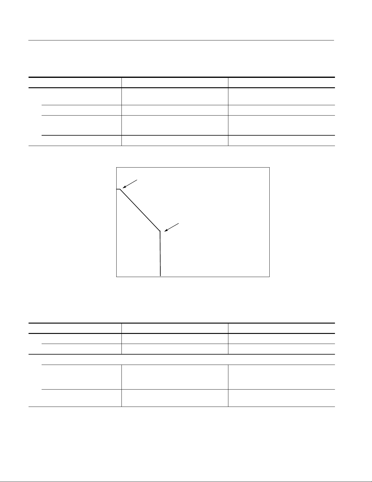
1
Available max current of Step Generator in 100 mA and 200 mA/step.
Specifications
Step Generator Current
2A
0A
0V 8V 10V
Load Voltage
2
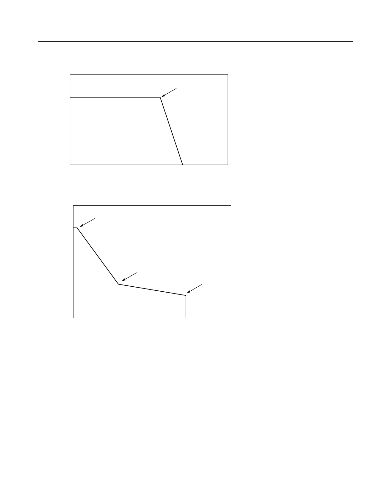
Step Generator max voltage output, in 2 V/step.
0.01 A, 40 V
40 V
Step Generator Voltage
8V,2A
0.2A,15V
15 V
10 V
0V
10 mA
0.2 A
0.5A,10V
0.5 A
Load Current
370B Service Manual
1- 9
Page 34
Specifications
Table 1- 3: AUX Supply
Characteristic Performance Requirement Operating Information
Range From --40 to +40 volts, with 20 mV step
resolution.
Accuracy Within 50 m V + 1.5% of total output.
Output current
At least 100 mA at 20 V. At least 10 mA at
40 V.
Ripple pulse noise Less than 50 mV
3
Max voltage output and current of AUX SUPPLY.
40 V
AUX Supply Voltage
20 V
0V
10 mA
3
p--p.
0.01 A, 40 V
0.1A,20V
100 mA
Load Current
Table 1- 4: Non-store Vertical Deflection System
Characteristic Performance Requirement Operating Information
Cursor WINDOW
Accuracy (typical) Within 0.06 division.
Collector/Base current
Range 1 A/div to 2 A/div in a 1--2--5 sequence.
x10 MAG extends maximum sensitivity to
100 nA/div (1 nA resolution).
Accuracy (typical) Within 2% of WINDOW cursor readout + 0.1
x VERT/DIV setting.
1- 10
370B Service Manual
Page 35
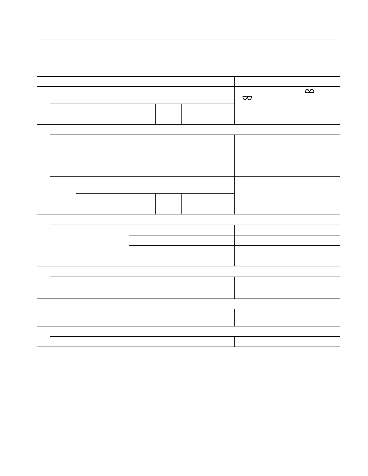
Table 1- 4: Non-store Vertical Deflection System (Cont.)
Characteristic Operating InformationPerformance Requirement
Maximum displayed noise or
ripple
Max volts range 16 V 80 V 400 V 2000 V
Specifications
Except tor switching noise at + and
-- mode.
Noise or ripple 1 A
p--p
1 A
p--p
2 A
p--p
Emitter current
Range 1 nA/div to 2 mA/div in a 1--2--5 sequence.
x10 MAG extends maximum sensitivity to
100 pA/div.
Accuracy Within 2% of WINDOW cursor readout +0.1 x
VERT/DIV settings + 1 nA
Maximum displayed noise or
Depending on setting of MAX PEAK VOLTS
ripple
Max Volts Range 16 V 80 V 400 V 2000 V
Noise or Ripple 1nA
p--p
1nA
p--p
2nA
p--p
Step generator display
Range (typical) 1 step/division
1 step/10 divisions With x10 MAG
10 steps/division With STEP MULTI .1 x
Accuracy Within 0.3 division.
Display offset (typical)
Range
10 divisions with 0.1 div resolution.
Accuracy Within .% of offset + 0.1 x VERT/DIV setting
5 A
5nA
p--p
Collector Supply Polarity is either +LEAKAGE or --LEAKAGE mode.
p--p
Display x10 MAG (typical)
Accuracy Within 1.5% of window cursor readout + 0.3
x VERT/DIV setting.
Display invert (typical)
Accuracy Within 0.1 x VERT/DIV setting
370B Service Manual
1- 11
Page 36
Specifications
Table 1- 5: Digital Storage Vertical Acquisition
Characteristic Performance Requirement Operating Information
A/D converter
Resolution 10 bits for 10.24 divisions, 100 counts per
division.
Max data points 1024
Max sampling rate Line frequency x 1024
Min sampling rate Line frequency x 2
Collector/Base current
Range 1 A/div to 2 A/div in a 1 -- 2--5 sequence.
x10 MAG extends maximum sensitivity to
100 nA/div (1 nA resolution).
Accuracy Within 1.5% of DOT cursor readout + 0.05 x
VERT/DIV setting.
Emitter current
Range 1 nA/div to 2 mA/div in a 1--2--5 sequence.
x10 MAG extends max sensitivity to
100 pA/div (1 pA resolution).
Accuracy Within 1.5% of DOT cursor readout + 0.05 x
VERT/DIV setting + 1 nA.
Step generator display
Range 1 step/division
1 step/10 divisions
10 steps/division
Accuracy Within 0.3 division.
Display offset
Range
Accuracy Within 1.5% of offset +0.06 x VERT/DI V
Display x10 MAG
Accuracy Within 1.5% of DOT cursor readout +0.3 x
Display invert
Accuracy Within 0.04 x VERT/DIV setting.
10 divisions in 0.1 division resolution.
setting.
VERT/DIV setting.
Collector supply polarity is either +LEAKAGE
or -- LEAKAGE
With x10 MAG
With STEP MULTI .1 x
1- 12
370B Service Manual
Page 37
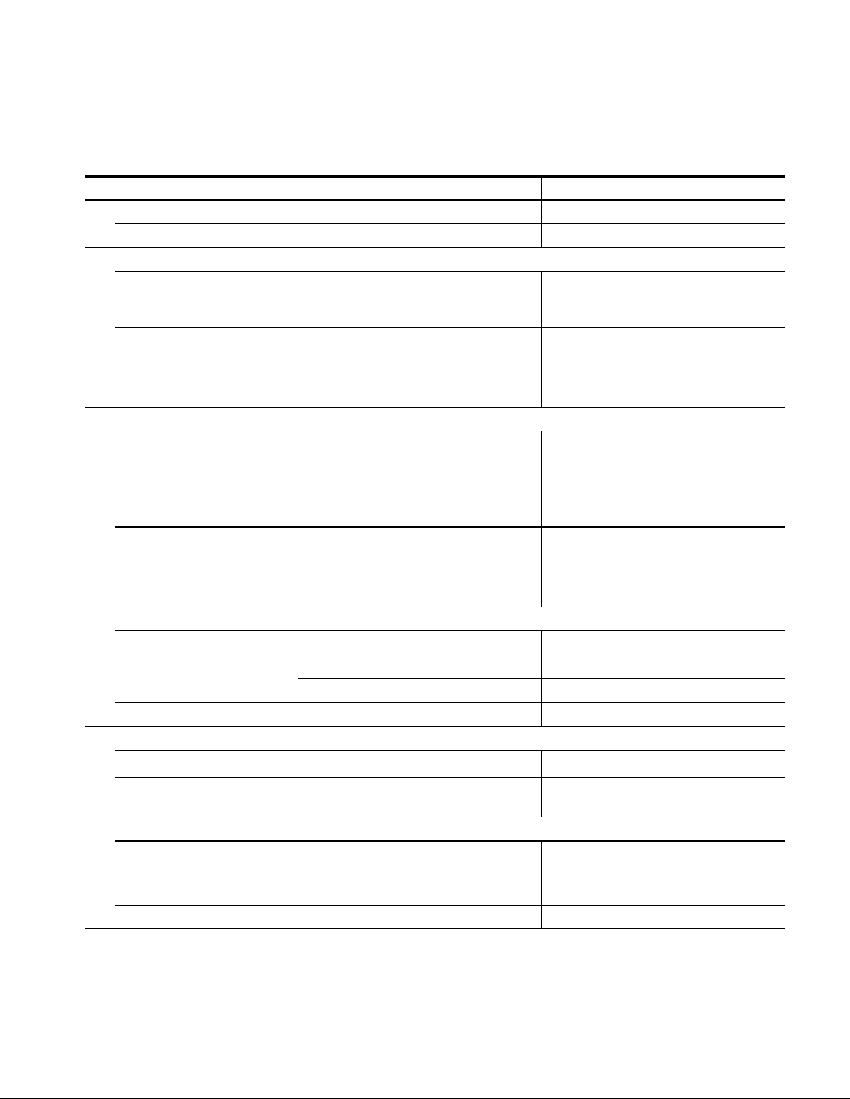
Table 1- 6: Non-store Horizontal Deflection System
Characteristic Performance Requirement Operating Information
Cursor WINDOW Cursor
Accuracy (typical) Within 0.06 division.
Collector volts
Range 50 mV/div to 500 V/div in a 1 --2--5 sequence.
x10 MAG extends maximum sensitivity to
5 mV/div (50 V resolution).
Accuracy (typical) Within 2% of WINDOW cursor readout + 0.1
x HORIZ/DIV setting.
Maximum displayed noise Less than 0.02% of MAX PEAK VOLTS
setting.
Base/Emitter volts
Range 50 mV/div to 5 V/div in a 1--2--5 sequence.
x 10 MAG extends maximum sensitivity to
5 mV/div (50 V resolution).
Specifications
Accuracy (typical) Within 2% of WINDOR cursor readout + 0.1 x
HORIZ/DIV setting.
Input impedance At least 100 MΩ.
Maximum displayed noise Less than 10 mV
Step generator display
Range 1 step/division
1 step/10 division With x10 MAG
10 steps/division With STEP MULTI .1 x
Accuracy Within 0.3 division.
Display offset
Range
Accuracy Within 1.5% of offset + 0.1 x HORIZ/DIV
Display x10 MAG
Accuracy Within 1.5% of window cursor readout + 0.3 x
Display invert
10 divisions in 0.1 division steps.
setting.
HORIZ/DIV setting.
p--p.
With 1 MΩ resistor connected between Base
and Emitter terminals, BASE OPEN
configuration, and 0 Number of Steps.
Accuracy Within 0.1 x HORIZ/DIV setting.
370B Service Manual
1- 13
Page 38
Specifications
Table 1- 7: Digital Storage Horizontal Acquisition
Characteristic Performance Requirement Operating Information
A/D converter
Resolution 10 bits for 10.24 divisions. 100 counts per
division.
Max data points 1024
Max sampling rate Line frequency x 1024
Min sampling rate Line frequency x 2
Collector volts
Range 50 mV/div to 500 V/div in a 1--2--5 sequence.
X10 MAG extends maximum sensitivity to
5 mV/div (50 V resolution).
Accuracy Within 1.5% of dot cursor readout + 0.05 x
HORIZ/DIV setting.
Base/Emitter volts
Range 50 mV/div to 5 V/div in a 1--2--5 sequences.
x 10 MAG extends maximum sensitivity to
5 mV/div (50 V resolution)
Accuracy Within 1.5% of dot cursor readout + 0.05 x
HORIZ/DIV setting.
Step generator display
Range 1 step/division
1 step/10 divisions
10 steps/division
Accuracy (typical) Within 0.3 division.
Display offset
Range
Accuracy Within 1.5% of DOT cursor readout + 0.01 x
Display x10 MAG
Accuracy Within 1.5% of DOT cursor readout + 0.3 x
Display invert
Accuracy Within 0.04% x HORIZ/DIV setting.
10 divisions in 0.1 division resolution.
HORIZ/DIV setting.
HORIZ/DIV setting.
With X10 MAG
With STEP MULTI .1 x
1- 14
370B Service Manual
Page 39

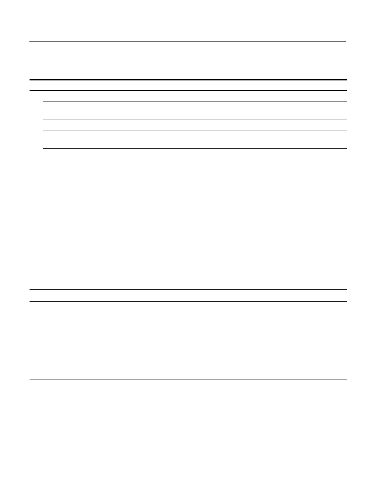
Table 1- 8: CRT and Readout
Characteristic Performance Requirement Operating Information
CRT
Type Electrostatic deflection
Phosphor P31
Acceleration potential 12 kV typical
Screen size 178mm(7 in) diagonal internal graticule and
on-screen scale factor readout.
Specifications
Total addressable points
1000 x 1000
(graticule area)
Geometry 0.5 minor division or less of tilt or bowing;
0.75 minor division or less of keystone.
Resolution At least 10 lines/div
Spot size Within 0.95 mm at screen center; elsewhere
on screen: within twice center value.
Orthogonality 90_,within0.3_
Trace rotation range (typical)
At least 3_
READOUT Automatic on-screen display. Over range
shown by a flashing display.
VERT/DIV 100 pA to 2 A
HORIZ/DIV 5mVto500V.
PER STEP 5nAto200mA,and5mVto2V.
OFFSET 4-digit value.
β or gm/DIV 500 x 10
50 x 10
-- 9
to 400 x 106for β and
-- 9
S to 400 S for gm
CURSOR 4-digit Horizontal and Vertical values without
x 10 MAG, 5-digit with MAG.
% of COLLECTOR PEAK VOLTS 0.0% to 100.0% in 0.1% step.
Aux Supply -- 40.00 V to + 40.00 V
370B Service Manual
1- 15
Page 40
Specifications
Table 1- 9: Adapter Connectors
Characteristic Performance Requirement Operating Information
Collector
Collector Sense
Maximum output voltage
Maximum output current
Base
Base Sense
Maximum output voltage
Maximum output current
Emitter
Emitter Sense
Maximum output voltage
Maximum output current
Step Gen Out connector
Maximum output voltage
Maximum output current
Aux Supply Connector
Maximum output voltage
and current
2000 V
20 A
400 V
20 A
40 V
20 A
40 V
2A
40 V @ 10 mA, or
20 V @ 100 mA.
Ext Base or Emitter Connector
Maximum input voltage
Maximum input current
1- 16
40 V
2A
370B Service Manual
Page 41
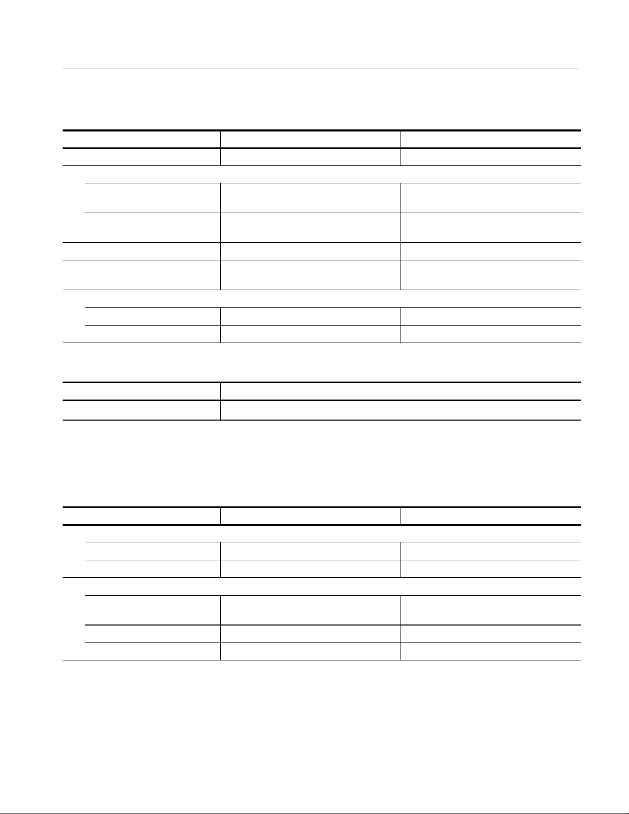
Table 1- 10: Power Supply
Characteristic Performance Requirement Operating Information
Rating voltage 115 VA C / 2 3 0 VAC
Line voltage range
115 VA C High 107 VAC to 132 VAC
Low 90 VAC to 110 VAC
230 VAC High 214 VAC to 250 VAC
Low 180 VAC to 220 VAC
Frequency range 48.0 to 63.0 Hz
Power consumption Max. 400 W, 3.5 A
Typical 120 W, 1.3 A at 115 V, 50 Hz
Fuse
115 VA C 125 V, 4 A, Sl ow-Blow
230 VAC 250 V, 2 A, Slow-Blow
Specifications
Table 1- 11: Surge Current
Characteristic Description
Surge current
80 A peak (25_C) for 5 line cycles, after product has been turned off for at least 30 s.
Mechanical Specifications
Table 1- 12: Mechanical Specification
Characteristic Performance Requirement Operating Information
Net weight
Standard instrument Approx. 37 k g (82 lb)
Option 1R Approx. 38 k g (84 lb)
Dimensions
Height 326 mm (12.8 in) with feet
310 mm (12.2 in) without feet
Width 429 mm (16.9 in)
Depth 635 mm (25.0 in)
370B Service Manual
1- 17
Page 42

Specifications
Functional Specifications
Table 1- 13: Digital Storage Acquisition Mode
Characteristic Performance Requirement Operating Information
Normal Acquires and displayed each curve.
Envelope
Vertical envelope Acquires and displays the maximum and
minimum vertical excursion of each curve.
Horizontal envelope Acquires and displays the maximum and
minimum horizontal excursion of each curve.
Averaging Acquires and displays the average of last 16
acquisitions.
Table 1- 14: Text Display
Characteristic Performance Requirement Operating Information
Alphanumeric character
Set (1)
Alphanumeric character
Set (2)
Maximum text string length 24 characters
Character size Approximately 3 mm height, 2 mm width.
ASCII character set except double quote (”),
u is recognized as )
GPIB-accessible with the TEXT command.
A,B,....,Y,Z,(Space),m, u,
n,o,,,0,........,9,--,*,(,),
Accessible with the Position Control buttons.
1- 18
370B Service Manual
Page 43

Environmental Specifications
Table 1- 15: Environmental Specification
Characteristic Performance Requirement
Temperature
Operating +10 _Cto+40_C
Non-operating -- 2 0 _Cto+60_C
Transportation -- 4 0 _Cto+65_C
Temperature gradient
Specifications
Operating
Non-operating
Humidity
Operating and Non-operating Five cycles (120 hours) with equipment tested at 80% relative humidity. Tested on-operating
Relative Humidity
Operating 20% to 80% (no condensation)
Storage 10% to 90% (no condensation)
Transportation 5% to 95% (no condensation)
Altitude
Operating Up to 3.0 km (10000 feet).
Non-operating Up to 15 km (50000 feet).
Vibration
Operating 2.352 m/s2(0.24 G
Shock (non--operating) 196 m/s2(20 G), hal f-sine, 11 ms duration.
≤15 _C per hour (no condensation)
≤30 _C per hour (no condensation)
at 60 _C and operating to meet MIL-STD-810C method 507.1 procedure IV, modified as
specified in MIL-T-28800B paragraph 4.5.1.1.2.
Maximum wet bulb temperature shall be 29 _C.
Maximum wet bulb temperature shall be 40.0 _C.
Maximum wet bulb temperature shall be 45.0 _C.
Maximum operating temperature decreases 1 _C each 1,000 feet above 1.5 km (5,000 feet).
),5Hzto500Hz
rms
Three shocks per axis in each direction (18 shocks total)
Bench handling
Operating Drop from 10 cm (4 in) tilt, or 45 _ which ever less (Tilt not to balance to point.)
Packaged transportation drop Meets the limits of the National Safe Transit Association test procedure 1A--B--2; 10 drops of
61 cm (24 in).
Packaged transportation vibration Meets the limits of the National Safe Transit Association test procedure 1A--B--1 ;excursion of
2.5 cm (1 in) p--p at 4.63 Hz 10.8ms/s
2
(1 .1 G) for 60 minutes.
370B Service Manual
1- 19
Page 44

Specifications
Table 1- 16: Certifications and Compliances
Category Standards or description
EC Declaration of Conformity -EMC
Emissions EN 55011 Class A Radiated and Conducted Emissions
Immunity EN 61000-4-2 Electrostatic Discharge Immunity
Australia/New Zealand
Declaration of Conformity -- EMC
Safety UL3111-1
Self-Declaration EN 61010-1 with second amendment
Installation Category Power input -- Installation Category II (as defined in IEC 61010--1, Annex J)
Meets intent of Directive 89/336/EEC, amended by 93/68/EEC;
EN 61326-1: 1997 Product Family Standard for Electrical Equipment for Measurement,
Control, and Laboratory Use-EMC Requirement.
EN 61000-3-2 Power Line Harmonic
EN 61000-3-3 Line Voltage Alteration and Flicker
EN 61000-4-3 Radiated RF Electromagnetic Field Immunity
Note: The output level of Step Generator may vary in this test.
EN 61000-4-4 Electrical Fast Transient/Burst Immunity
EN 61000-4-5 Surge Immunity
Note: The output level of collector supply may decrease in this test.
EN 61000-4-6 Conducted Disturbance induced by RF Field Immunity
EN 61000-4-8 Power Frequency Electromagnetic Field Immunity
EN 61000-4-11 Voltage Drop, Short Interruptions and Voltage Variations Immunity
Note: The output of Collector Supply is disabled after this test.
Complies with EMC provision of Radio Communications Act per the following standard:
Industrial, Scientific, and Medical Equipment: 1992
CAN/CSA C22.2 NO. 1010.1
Pollution Degree Pollution degree 2 (as defined in IEC 61010--1)
1- 20
370B Service Manual
Page 45

Specifications
Table 1- 17: Installation category and Pollution degree Descriptions
Characteristics Description
Installation category Terminals on this product may have different installation category designations. The
installation categories are:
Category Descriptions
CAT III Distribution-level mains (usually permanently connected).
Equipment at this level is typically in a fixed industrial
location
CAT II Local-level mains (wall sockets). Equipment at this level
includes appliances, portable tools, and similar products.
Equipment is usually cord-connected
Pollution degree
CAT I
A measure of the contaminates that could occur in the environment around and within a
product. Typically the internal environment inside a product is considered to be the same
as the external. Products should be used only in the environment for which they are rated.
Category Descriptions
Pollution Degree 1 No pollution or only dry, nonconductive pollution occurs.
Pollution Degree 2 Normally only dry, nonconductive pollution occurs.
Pollution Degree 3
Pollution Degree 4 Pollution that generates persistent conductivity through
Secondary (signal level) or battery operated circuits of
electronic equipment
Products in this category are generally encapsulated,
hermetically sealed, or located in clean rooms.
Occasionally a temporary conductivity that is caused by
condensation must be expected. This location is a typical
office/home environment. Temporary condensation occurs
only when the product is out of service.
Conductive pollution, or dry, nonconductive pollution that
becomes conductive due to condensation. These are
sheltered locations where neither temperature nor humidity is
controlled. The area is protected from direct sunshine, rain,
or direct wind.
conductive dust, rain, or snow. Typical outdoor locations.
370B Service Manual
1- 21
Page 46

Specifications
GPIB Interface
The IEEE-488-1978 (GPIB) standard defines the GPIB interface functions and
the allowed subsets of those functions.
Table 1- 18: GPIB Interface
Function Implemented As
Source handshake SH1
Acceptor handshake AH1
Tal k er T6
Listener L4
Service request SR1
Remote local RL2
Parallel poll PP0
Device clear DC1
Device trigger DT0
Controller C0
1- 22
370B Service Manual
Page 47

Operating Information
Page 48

Page 49

Operating Information
This section provides the following information:
H Initial inspection procedure
H Installation procedures
H Kelvin Sense
H Rackmounting Information
H Repackaging procedure for shipment
Installation
Initial Inspection
Power Source Information
This instrument was thoroughly inspected for mechanical and electrical defects
before shipment. It should be free of mars or scratches and meet or exceed all
electrical specifications. To confirm this, inspect the instrument for physical
damage incurred in transit and test the electrical performance by following the
First Time Operation in the 370B Programmable Curve Tracer User Manual.
This instrument operates from a power source having a neutral or near ground
(earth) potential. It is not intended for operation from two phases of a multiphase system, nor across legs of a single phase, three wire system. This
instrument can be operated from either a 115 volt or 230 volt nominal supply
source, 48 to 63 Hz. Table 2-- 1 is a listing of the line voltage ranges, line
frequency range, and power consumption.
Table 2- 1: Line voltage ranges
RANGE switch NORM AL switch
115 VA C 230 VAC
HIGH 107 VAC to 132 VAC 214 VAC to 250 VAC
LOW 90 VAC t o 110 VAC 180 VAC to 220 VAC
Power consumption
370B Service Manual
Max. 400 W, 3.5 A at 132 V, 60 Hz
Typical 120 W, 1.3 A at 115 V, 50 Hz
2- 1
Page 50
Getting Started
Operating Voltage
Selection and Line Fuse
Verification
The LINE VOLTAGE SELECTOR switches (NOMINAL and RANGE, located
on the rear panel) allow selection of the operating line voltage. To select the
correct operating line voltage:
1. Disconnect the 370B from the AC power source before changing the
operating voltage.
2. Select the nominal AC power source voltage with the NOMINAL switch,
and
3. Select the operating line voltage with the RANGE switch.
CAUTION. To prevent damage to the instrument, always check the settings of the
LINE VOLTAGE SELECTOR switches located on the rear panel of the 370B
before connecting the instrument to the line voltage source.
To verify that the power input fuse is for the nominal AC source voltage
selected, perform the following:
1. Use the small straight slot screwdriver to pry the cap (with the attached fuse
inside) out of the fuse holder.
2. Verify proper fuse value:
Power Cord Information
Nominal voltage 230 V 2 A medium blow
Nominal voltage 115 V 4 A medium blow
3. Install the proper fuse and reinstall the fuse holder cap.
A power cord with the appropriate plug configuration is supplied with each
instrument. The color coding of the power cord conductors appears in Table 2--2.
Also, should you require a power cord plug other than that supplied, refer to
Table 2--3, Power Cord Identification.
Table 2- 2: Power Cord Color Conductor Identification
Conductor Color Alternate
Ungrounded (Line) Brown Black
Grounded (Neutral) Light Blue White
Grounded (Protective Ground) Green / Yellow Green / Yellow
2- 2
370B Service Manual
Page 51
Getting Started
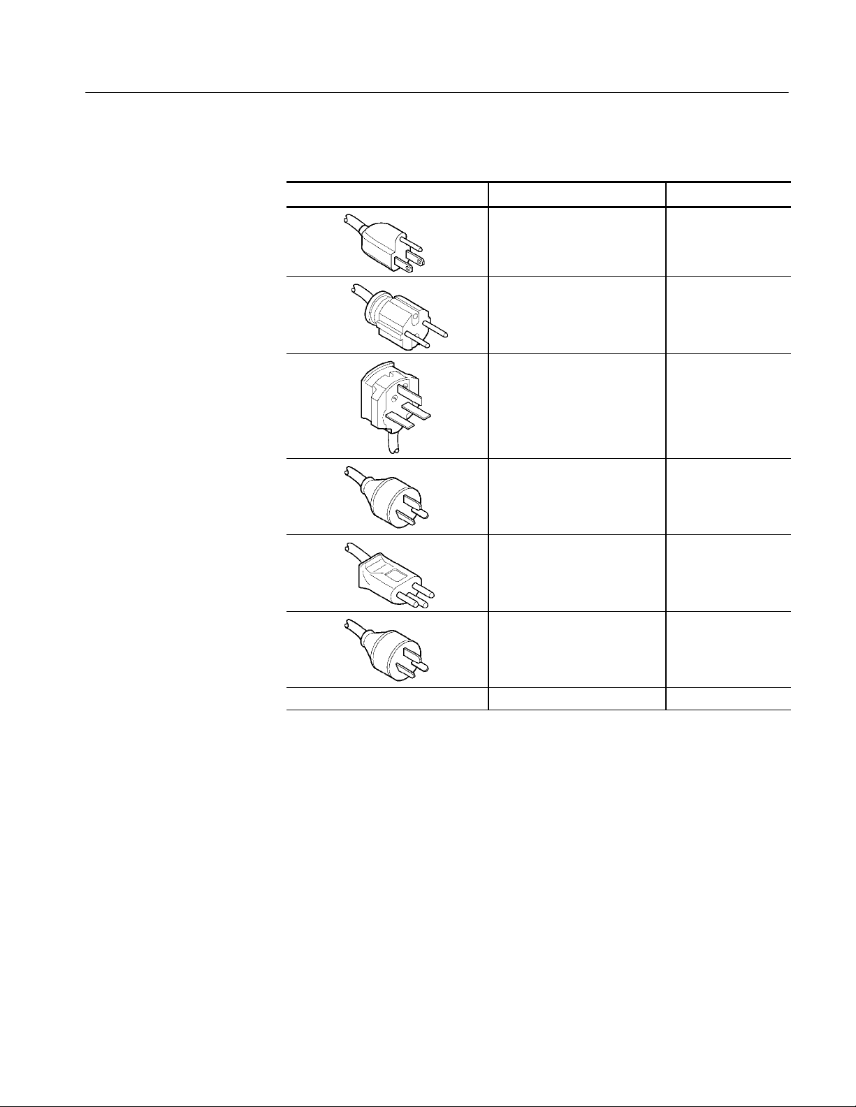
Table 2- 3: Power cord identification
Plug configuration Normal usage Option number
North America
125 V
Europe
220 V
United Kingdom
240 V
Australia
240 V
Switzerland
220 V
China
240 V
Standard
A1
A2
A3
A5
AC
370B Service Manual
No power cord supplied. A9
2- 3
Page 52
Getting Started
WARNING. This instrument operates from a single phase power source, and has a
detachable three-wire power cord with a two-pole, three-terminal grounding type
plug. The voltage to ground (earth) from either pole of the power source must
not exceed the maximum rated operating voltage (250 volts rms).
Before making connection to the power source, make sure that the instrument is
set for the pow er source voltage, and is equipped with a suitable plug (two-pole,
three-terminal, grounding type).
This instrument is safety class 1 equipment (IEC* designation). All accessible
conductive parts are directly connected through the grounding conductor of the
power cord to the grounding contact of the pow er plug. Therefore, the power
plug must only be inserted in a mating receptacle with a grounding contact. Do
not defeat the grounding connection. Any interruption of the grounding
connection can create an electric shock hazard.
For electric shock protection, connect the instrument to ground before connecting to the instrument input or output terminals.
* International Electrotechnical Commission.
Operating Temperature
The 370B can be operated where the ambient air temperature is between +10
and +40
_C. After storage at temperatures outside the operating limits, allow the
_C
chassis temperature to reach the safe operating limits before applying power. The
370B is cooled by air drawn in through the air filter on the rear panel and blown
out through holes in the side panels. For proper instrument cooling, provide
adequate clearance on the rear and sides of the instrument to ensure free air flow
and dissipation of heat away from the instrument.
WARNING. Following use of the 370B at high power settings, the device, fixture,
or protective cover may be hot enough to cause injury. Avoid touching any of
these items until cooled.
2- 4
370B Service Manual
Page 53

Getting Started
Test adapter and
Protective cover
To use the 370B to display and measure the characteristic curves of most
devices, a test adapter and the protective cover must be installed. Four test
adapters are provided as standard accessories. Six other test adapters are
available as optional accessories. The test adapter is inserted into the adapter
connectors provided on the front panel. These connectors allow two devices to
be set up at a time.
WARNING. Dangerous voltage may appear at the front panel collector and base
terminals. To avoid injury or equipment damage, do not remove the protective
cover.
CAUTION. Double-wide test adapters are designed to fit in the left set of adapter
connectors. If you try to forcibly install a double-wide test adapter in the right
side, you might damage the connector. The connectors are identified by the
following numbers:
A1006
A1007
A1009
A1010
Kelvin Sense
The 370B provides the adaptor connector equipped with Kelvin sense terminals.
The Kelvin sense is the way to measure voltage with two independent terminals
connecting to each of DUT leads; the Force terminal that supplies power and the
Sense terminal senses the voltage. By using the Kelvin sense mechanism, you
can make a high precision measurement because that the effect of conductance
from the contact between the cables and DUT leads is suppressed to a minimum.
The Sense terminals in the 370B adaptor connector and the A1001 through
A1005 test adaptors are for Kelvin sensing. The measurement can be performed
without Sense terminals, however, if you need high precision measurement, use
the those terminals.
370B Service Manual
2- 5
Page 54
Getting Started
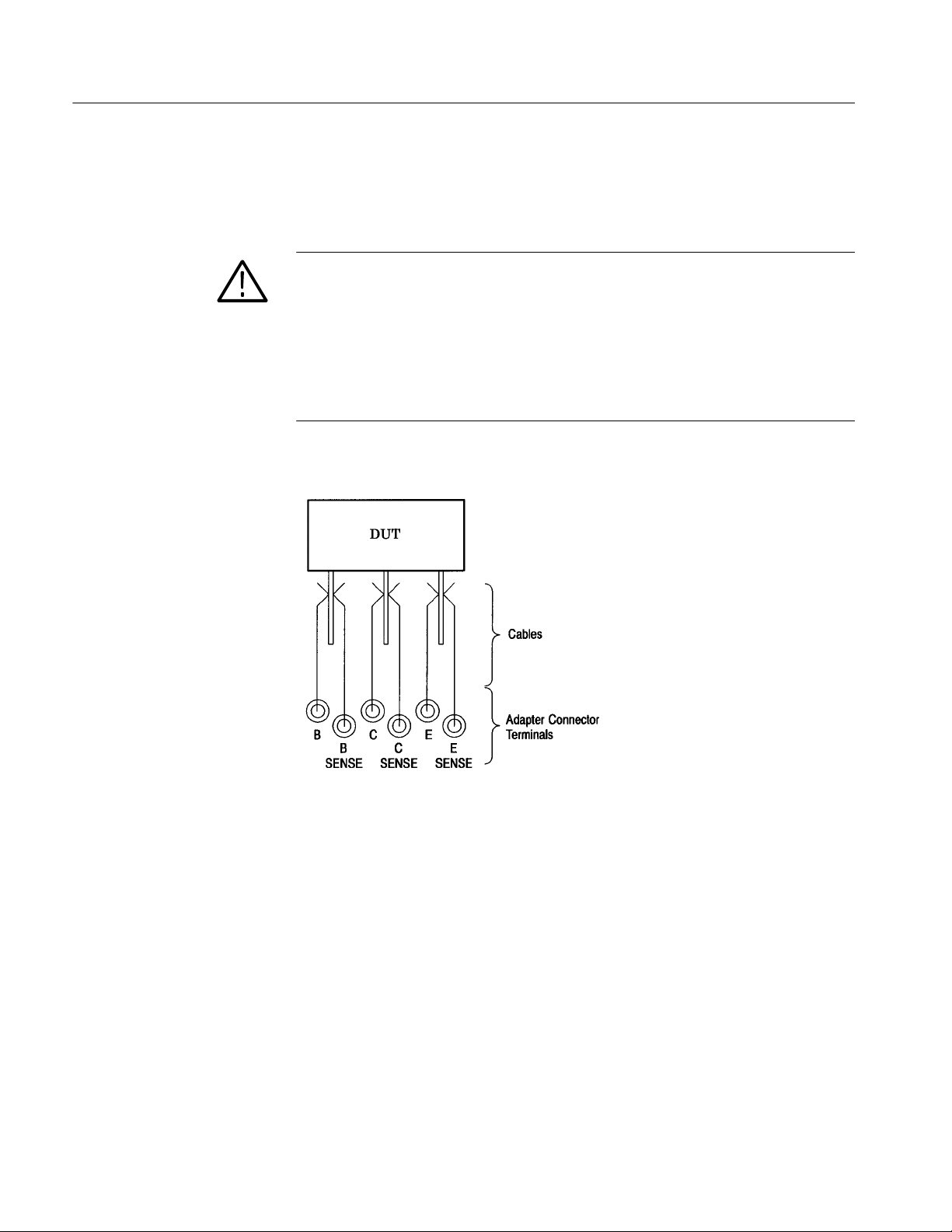
Connections for Kelvin
Sensing
When a DUT does not fit in any of the test adaptors and you prepare a specific
test adaptor, for example, use cables to connect terminals and DUT leads as
shown in Figure 2--1 for Kelvin sensing.
CAUTION. Confirm that the the DUT leads and the force terminals: C, B and E
are firmly connected. Making improper connections may cause the DUT to be
broken. Before a measurement, also verify that the cables are not down and the
contact between the terminals and cables are made properly. To avoid electric
shock and damage to the instrument, perform measurement only within the
protective cover. Do not disable the interlock mechanism and/or do not take the
cables out of the protective cover to perform measurement without or outside the
cover.
2- 6
Figure 2- 1: Example of Kelvin sense connection
370B Service Manual
Page 55
Rackmounting Information
Getting Started
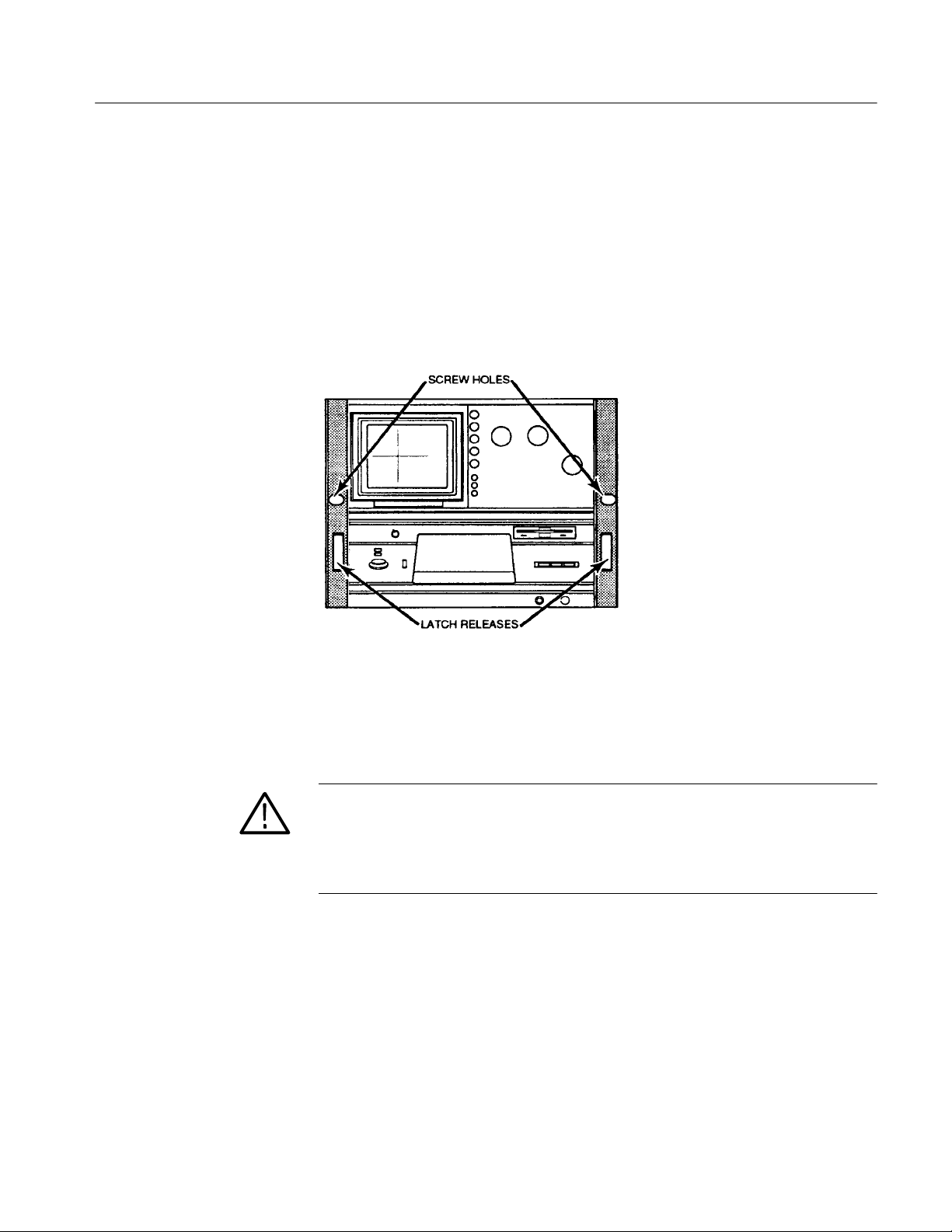
Latching
The 370B incorporates a spring-latch design built into the rackmounting ear. To
release, pull the rackmount latch release (see Figure 2--2). To relatch, push the
rackmount latch release until the spring latches engage.
For those applications that require additional rackmounting security, the
rackmounting ears of the 370B are drilled for screw fasteners (see Figure 2--2).
Figure 2- 2: Location of the Rackmount Latch Release
Rackmounting
370B Service Manual
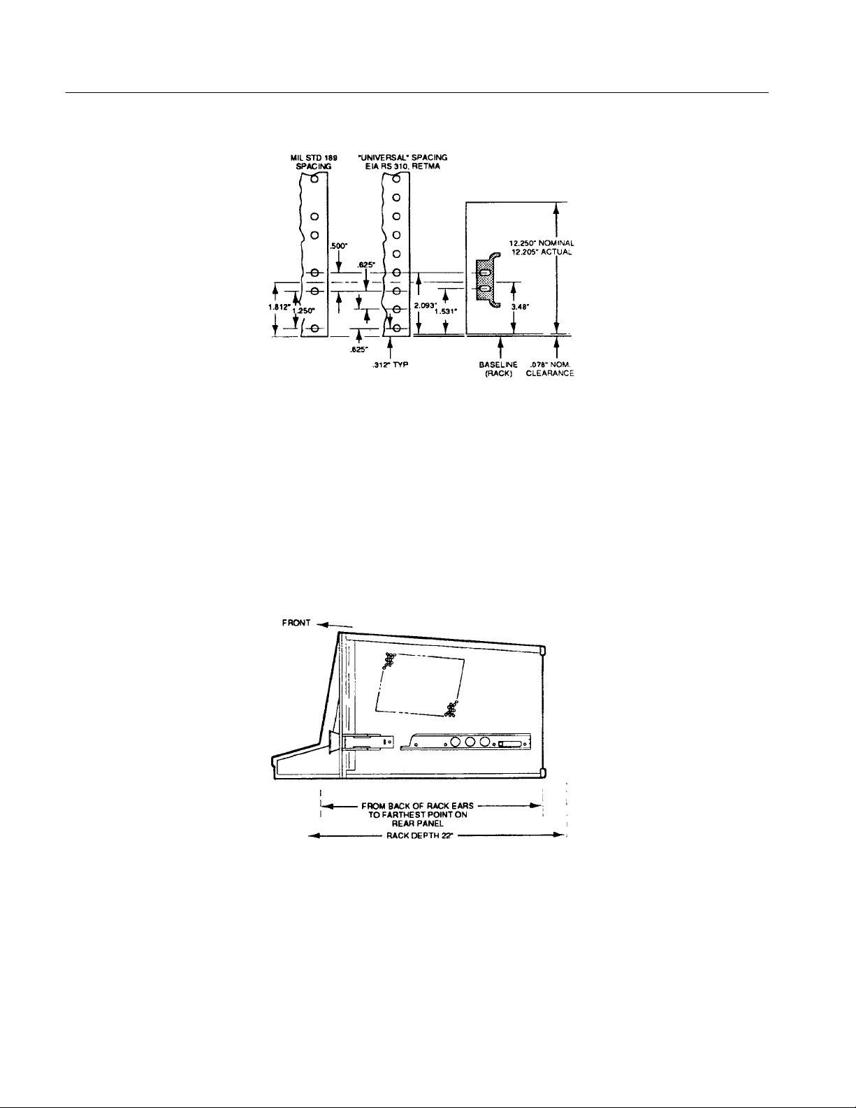
The 370B fits most commercial consoles and 19-inch racks with rail holes that
conform to universal spacing. See Figure 2--3 for hole spacing details.
WARNING. The 370B weighs more than 36Kg(80 lb). To avoid personal injury,
use care when lifting the instrument, and where required, seek help in lifting and
positioning the 370B into the rack. Once the 370B is installed in a rack, use care
that when extended, the 370B does not tip the rack forward, causing personal
injury or instrument damage.
2- 7
Page 56
Getting Started
Figure 2- 3: Rackmount hole spacing
When rackmounting the 370B, take note of the following: Allow one inch clearance above and below, and on the left and right sides of the 370B for air circulation. Allow at least three inches of clearance between the 370B rear panel and the
rack enclosure for adequate cooling air and to provide cable clearance. The depth
of the 370B from behind the rack ears to the rear panel is 480mm (18.9 in).
The rack depth must be at least 559 mm (22 in) (see Figure 2--4) to meet the rear
clearance requirement.
2- 8
Figure 2- 4: Rackmounting Length and Clearance
The 370B is 312 mm (12.25 in) high, a multiple of 45 mm (1.75 in) (the
standard rack spacing). If the 370B is installed in a rack with standard hole
spacing, and positioned some multiple of 45 mm (1.75 in) from the bottom or
top, all holes should line up and no drilling should be required.
370B Service Manual
Page 57

Getting Started
The slide-out tracks mount easily to the rack front and rear vertical mounting
rails if the inside distance between the rails is within 503 mm (19.8 in) to
674 mm (26.5 in). If the tracks are to be installed in a rack having other
dimensions, provide extra support (for example, extensions to the rear mounting
brackets) for the rear ends of the slide-out tracks.
The front rack rails must be at least 17 inches apart. The front lip of the
stationary-track section mounts in front of the rail. (Use bar nuts behind
untapped front rails.) The front lip of the stationary track section must mount in
front of the front rail to allow the 370B spring latch to function properly.
The slide-out tracks consist of two assemblies, one for each side of the instrument. Each assembly consists of three sections (see Figure 2--5). The stationary
section of each track attaches to rack rails as shown in Figure 2--6. The chassis
section mounts on the instrument and is installed at the factory. The intermediate
section fits between the other two sections, allowing the instrument to be fully
extended out of the rack.
Figure 2- 5: Rackmounting Hardware
370B Service Manual
2- 9
Page 58

Getting Started
The stationary and intermediate sections for both sides are shipped as a matched
set and should not be separated. The package includes matched sets for both
sides and mounting hardware. To identify the assemblies, note that the automatic
latch and intermediate section latch stop holes are located near the top when the
matched sets are properly mated to the chassis sections.
To mount the instrument in a rack, perform the following:
1. Select the appropriate holes in the rack rail, using Figure 2--3 as a guide.
2. Mount the stationary-track sections to the front rack rails with truss head
screws (and bar nuts, if necessary).
3. Mount the stationary-track sections to the rear rails, using one of the
methods depicted in Figure 2--6. Note that the rear mounting bracket can be
installed to fit either deep or shallow cabinet racks.
4. After mounting the instrument in the slide-out tracks, adjust for proper width
by loosening the front and rear screws and allowing the slides to seek the
proper width. Center the instrument, then tighten the screws.
Figure 2- 6: Mounting Stationary Rackmount Sections
2- 10
370B Service Manual
Page 59

Getting Started
5. Push the instrument into the rack, and check that the automatic spring latch
engages the spring latch catch to hold the instrument in place.
6. Extend the instrument out of the rack by pulling the rackmount latch releases
on the front panel (see Figure 2--2) out to disengage the spring latches. Then,
pull the instrument out.
7. Once the instrument is out of the rack, press the latch release and push the
instrument back into the rack.
Rackmount to Cabinet
Conversion
To convert the 370B rackmount version to a cabinet model, use the following
procedure (see Figure 2-- 7):
1. Remove the bracket from each comer of the instrument rear panel.
2. Replace the left and right side panels with cabinet model side panels.
3. Mount a carrying handle assembly on the left and right sides of the top.
4. Fasten a foot at each corner on the bottom of the instrument.
370B Service Manual
2- 11
Page 60

Getting Started
Cabinet to Rackmount
Conversion
To convert the 370B cabinet model to a rackmount version, use the following
procedure (see Figure 2-- 7):
Figure 2- 7: Cabinet-to-Rackmount Conversion
1. Remove the bracket from each comer on the rear panel.
2. Replace the side panels with rackmount version side panels.
3. Attach brackets at each comer on the rear panel.
4. Remove both carrying handle assemblies:
a. Remove the plastic retainer caps that conceal the screws located at each
end of the handle.
b. Remove the screw, spacer and bar nut, then lift off the carrying handle
assembly.
2- 12
370B Service Manual
Page 61

Repacking for shipment
Getting Started
If this instrument is to be shipped long distances, we recommend that the
instrument be repackaged the same as when it arrived. The cartons and packaging material in which your instrument was shipped should be saved and used for
this purpose.
If your instrument is to be shipped to a Tektronix Service Center for service or
repair, attach a tag to the instrument showing the following:
Owner of the instrument (with address)
Name of a person at your firm to contact
Instrument type
Instrument serial number
Description of the service required
If the original packaging is unfit for use or not available, package the instrument
as follows:
1. Obtain a corrugated cardboard shipping carton with a 170kg(375lb) test
strength that has inside dimensions at least six inches greater than the
instrument dimensions.
2. Surround the instrument with polyethylene sheeting to protect the finish.
3. Cushion the instrument on all sides by tightly packing dunnage or urethane
foam between the carton and the instrument, allowing three inches on all
sides.
4. Seal the carton with shipping tape or with an industrial stapler.
5. Write the address of the Tektronix Service Center and your return address on
the carton in one or more prominent locations.
370B Service Manual
2- 13
Page 62

Getting Started
2- 14
370B Service Manual
Page 63

Theory of Operation
Page 64

Page 65

Theory of Operation
This section describes the operation of the 370B Programmable Curve Tracer
circuits. The section is divided into two parts: Block Diagram Description and
Detailed Circuit Operation.
Block Diagram Description
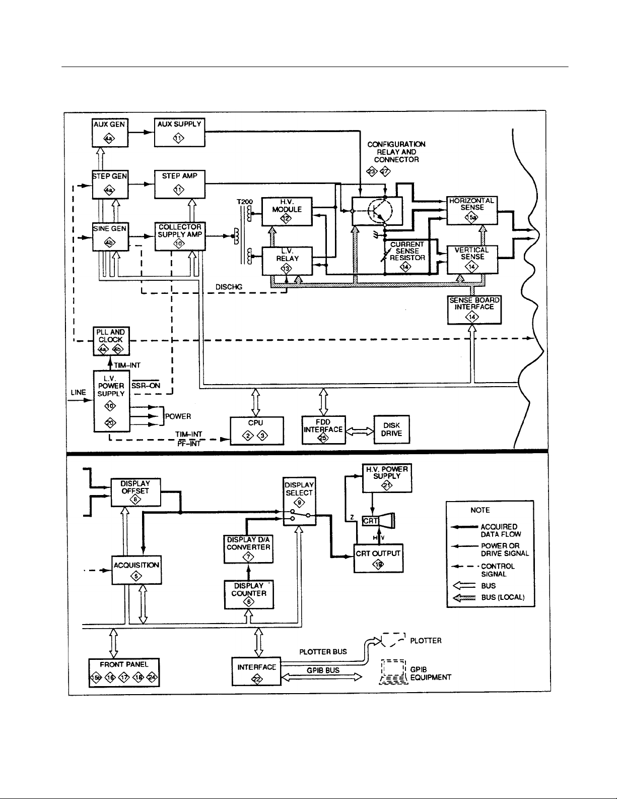
The following description is an overview of the 370B operation. Figure 3--1 on
page 3--3 is an overall block diagram of the 370B. The numbers enclosed in
diamonds within each block in Figure 3--1 indicate the schematic diagrams
associated with the block.
The 370B is a static and dynamic semiconductor tester that displays and allows
measurement of static and dynamic semiconductor characteristics obtained under
simulated operating conditions.
The 370B consists of five major functional sections:
H Collector Supply
H Data Acquisition and Display
H Control and Processing
H Interface
H Power Supply
370B Service Manual 3-1
Page 66

Theory of Operation
Stimulus Generators
The Stimulus Generators simulate operating conditions for the DUT by
producing voltages and currents that are applied to the DUT. They include the
Collector Supply, the Step Generator, the Aux Supply, and the PLL and Clock
Circuits.
The Collector Supply produces sine-wave ac, full-wave rectified sine waves
(positive and negative), and positive and negative DC voltages. The amplitude of
the output can be varied from 0 to 2000 volts. The Collector Supply output is
applied to either the collector or the base (or equivalent) terminal of the device
under test.
The Step Generator Circuit produces ascending or descending steps of current or
voltage at a normal rate of one step for each half-sine wave of the Collector
Supply. The amount of current or voltage per step, total number of steps and
offset voltage and current can be controlled. This Step Generator output may be
applied to either the base or the emitter (or equivalent) terminals of the device
under test.
The Auxiliary Supply produces auxiliary power for the DUT. The output voltage
range is 0 to 40 volts. This output can be applied to any terminal of the DUT.
3- 2 370B Service Manual
Page 67
Theory of Operation
Figure 3- 1: 370B Block Diagram
370B Service Manual 3-3
Page 68

Theory of Operation
The PLL and Clock Circuit generates a synchronous signal for the Step
Generator and the Sine Wave generator. This Circuit also generates synchronous
signals for the Acquisition Circuits.
This block consists of the following circuits.
AUX GEN Circuit
STEP GEN Circuit
SIN GEN Circuit
PLL and CLOCK Circuit
AUX SUPPLY Circuit
Collector Supply Amp Circuit
Step Amp Circuit
H.V. Module Circuit
L.V. Relay Circuit
Collector Terminal Circuit
Data Acquisition and
Display
These circuits sense, acquire, and display the effect of the Collector Supply and
Step Generator on the DUT. The block consists mainly of the Sense Circuit, the
Acquisition Circuit, the Digital Display Circuit, and the Display Circuit.
The Sense Circuit senses and amplifies voltages and currents of each terminal of
the DUT. This circuit also compensates for errors produced by IR drops between
the DUT terminals and the supply. The amplifier sensitivity is controllable.
The Acquisition Circuit converts sensed analog data into digital data, that is, the
fetch and A/D convert functions. This acquired data is sent to the CPU Circuit.
The Digital Display Circuit converts digital data into analog display signals. This
digital data includes stored curve and operating information.
The Display circuit selects store or non-store data and displays curves and 370B
operating information.
The Data Acquisition and Display Circuits consist of the following:
Acquisition Circuit
Display Counter Circuit
Display D/A Converter Circuit
Display Offset Circuit
Display Select Circuit
Vertical Sense Circuit
Sense Board Interface Circuit
Horizontal Sense Circuit
CRT Output Circuit
H.V. Power Supply Circuit
3- 4 370B Service Manual
Page 69

Theory of Operation
Control and Processing
These circuits control the 370B and process acquired data. They include the CPU
Circuit, the Front Panel Circuit, and Floppy Disk Circuit.
The CPU Circuit controls an operations of the 370B, including Collector Supply
and Step Generator Control, Sense Circuit Control. CRT Display Control, Front
Panel Control, Floppy Disk Control, etc. The circuit also processes the acquired
data from the device under test. These operations are controlled by the microprocessor and its operating programs through the Address, Data, and Control Bus
lines.
The Front Panel Circuit interfaces the operator to the 370B. This circuit reads
keys, switches and rotary encoder information to set the 370B to the desired
measurement condition. This also displays these settings to the operator by LED
and numerical displays.
The Floppy Disk Circuit memorizes acquired data from the device under test and
the 370B setting information. The data and information are stored in the 3.5-inch
floppy disk.
The Control and P rocessing Circuits consist of the following:
CPU Circuit
Front Panel Circuit
Floppy Disk Circuit
Interface
Power Supply
These circuits interface the microprocessor data with the printer and the
peripheral equipment. The circuit consists of the GPIB (General Purpose
Interface Bus) interface Circuit and the Printer Control Circuit.
These circuits supply low-voltage operating power to the 370B. These voltages
in turn are used to generate the high voltages, such as that used on the CRT.
There are two major circuits, the Power Supply and the Interrupt Signal
Generator.
The Power Supply converts the AC line voltages into DC voltages that supply
power for 370B operation.
The Interrupt Signal Generator generates timer interrupt and power fail interrupt
signals. These signals synchronize the 370B circuits, and provide a harmless
shutdown when power fails.
370B Service Manual 3-5
Page 70

Theory of Operation
Circuit Operation
This part of the Theory of Operation provides a description of the electrical
operation of the 370B. The number enclosed in a diamond preceding a portion of
text denotes the schematic diagram under discussion.
Interconnection
MPU
Memory
This circuit is located on the A1 Mother Board. The circuit connects inter-board
signals of the 370B. These signals include control signals, drive signals, data
signals, reference signals, sense signals, ground lines, and power supply lines.
The MPU circuitry is located on the A2 CPU board. It consists of a 68000
Microprocessor, Power-Up Reset Circuit Clock Generator, Buffers, Wait Timing
Generator, and Interrupt Control Logic Circuit.
The Memory circuit consists of the ROM, RAM, Battery Backup, address
selector, and buffers.
3- 6 370B Service Manual
Page 71
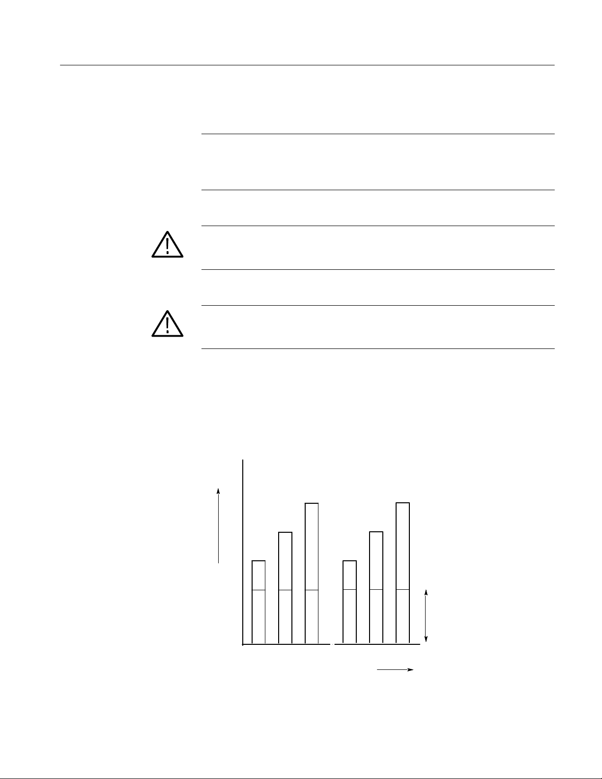
Theory of Operation
Generator <4a>
The Generator Circuit is located on the A3 A/D Board.
NOTE. The 370B has two step generator output modes, PULSED OFFSET
MODE and DC OFFSET MODE. The Pulse Offset is the default mode.
It can be changed to DC OFFSET MODE with the jumper J310 on the A3 A/D
Board.
CAUTION. When the device under test (DUT) is Normally-On type transistor,
Pulsed Offset will cause additional heat-up for the DUT. For the Normally-On
type transistor, DC Offset mode should be used.
CAUTION. When the device under test (DUT) is Normally-Off type transistor, DC
Offset will cause additional heat-up for the DUT. For the Normally-Off type
transistor, Pulsed Offset mode should be used.
Pulsed Offset. When the measurement mode is set to Single or Sweep, and the
Step Generator Voltage is set, the base line offset is applied only in the internal
measurement operation interval. Pulsed Offset functions only when Step
Generator is PULSE MODE, (short pulse or long).
The number of steps is in the case of 3.
VOLTAGE
or
CURRENT
0
PULSED OFFSET MODE
TIME
PULSED
OFFSET
370B Service Manual 3-7
Page 72
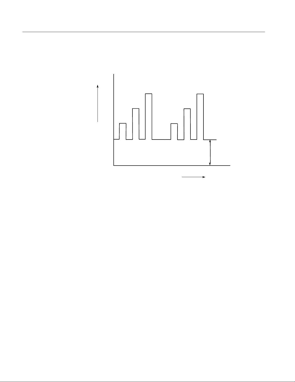
Theory of Operation
DC Offset. Base line offset voltage is always applied to the DUT in spite of Step
Generator mode and the Measurement Mode setting.
The number of steps is in the case of 3
VOLTAGE
or
CURRENT
DC OFFSET
0
DC OFFSET MODE
TIME
Collector Supply
Generator <4b>
Acquisition <5>
Display Counter Circuit
<6>
The Collector Supply Generator Circuit, located on the A3 A/D board, consists
of a Sine Wave Timing Generator, Sine Wave Generator, Collector Level Control
Circuit and High Voltage Sine Wave Attenuator Circuit. These circuits generate a
sine wave synchronized to the line frequency, which is the source of the
Collector signal.
The Acquisition Circuit, located on the A3 A/D Board, consists of an S/H
(Sample and Hold) and Select Circuit, A/D Circuit. A/D Timing Circuit,
Acquisition Memory Control Circuit, Acquisition Memory Circuit and Bus
Interface Circuit.
These circuits perform A/D conversion of the HD and VD signals from the A5
Display Control Board, write them into Acquisition memory, and transfer data to
the CPU.
The Display Counter Circuit is located on the A4 Digital Display Board. The
Display Counter Circuit consists of the Bus Buffer, the 4.5 MHz Oscillator,
Display Counter, Address Switch & CPU Control, Display RAM. Bus Transceiver. Dot Cursor Generator, Character & Latch Controller . These circuits
determine whether the CPU accesses the Display RAM, or whether the Display
Counter reads out the Display RAM contents to control signals for the digital
display.
3- 8 370B Service Manual
Page 73

Theory of Operation
Display D/A Converter
Circuit <7>
Display Offset Circuit <8>
The Display D/A C onverter Circuit is located on A4 Digital Display Board. The
Display D/A Converter Circuit consists of:
X data & Attribute Prefetch Latch
X--Y Data & Attribute Load Latch
X 10-bit DAC & Y 10-bit DAC
X & Y Low-pass Filter
Font Latch
Character ROM & Shift Register
X & Y Readout Position Latch
Readout Attribute Latch
8-bit Adder
X Readout Step Generator
X Readout DAC and Y Readout DAC
These circuits convert the digitized waveform data, readout data and cursor data
from the Display RAM into an analog signal and generate the z-axis signal.
The Display Offset Circuit is located on the A5 Display Control Board. The
Display Offset Circuit consists of the Control Logic Circuit, Offset D/A
Converter, Polarity Select Circuit, Source Select Circuit Zero & Invert Select
Circuit and Gain Select Circuit. These circuits select the horizontal and vertical
source inputs for the CRT display and provide them with calibrated offset
voltages to execute display functions such as DISPLAY OFFSET, MAG, CRT
CAL, DISPLAY INVERT and COLLECTOR SUPPLY POLARITY.
Display Select <9>
Collector Supply Amplifier
<10>
Step Amplifier <11>
The Display Select circuit is located on the A5 Display Control board. The
circuit consists of the Signal Select Logic Circuit, Unblank & Z Select Circuit,
and the Horizontal & Vertical Preamp. This circuit block selects and amplifies
the source inputs that are displayed on the CRT. Selection of the source inputs
are performed by the Signal Select Logic Circuit. The Z signal for the source
inputs is controlled by the Un-blank & Z Select Circuit.
This circuit is located on the A6 Collector Supply board and the A19 L.V.
Supply board. The circuit consists of the Collector Supply Amplifier Circuit, the
Voltage Limiter Circuit, the Current Limiter Circuit, the Limit Detector Circuit,
the Power Supply and Control Circuit and the Control Signal Decoder Circuit.
These circuits amplify signals from the Sine Wave Generator (located on the A3
A/D board) and provide driving voltage for collector supply transformer.
The Step Amplifier circuits are located on the A7 Step Generator board. This
circuit transforms the output of the Step Generator on the A/D Board into current
or voltage steps of various amplitudes to be applied to the device under test The
STEP AMPLITUDE switch determines the amplitude of the steps. The circuit
370B Service Manual 3-9
Page 74

Theory of Operation
consists of the Control Signal Latches, Relay Drivers, 0.5--1--2 Ranging Circuit,
and Step Amplifier. This circuit also includes the Auxiliary Supply Circuit.
H.V. Module <12>
Collector Supply Low
Voltage <13>
Vertical Sense <14>
This circuit consists of Transformer, H.V. Module, Relay Control Signal Decoder
Circuit and LOR Relay Circuit and is active when the MAX PEAK VOLTS is
set to 2000. These circuits provide the sine-wave ac, the full-wave rectified sine
wave and the DC voltage that range from 0 volts to 2000 volts peak. These
voltages are applied to the collector of the device under test via the A34 LOR
Relay board.
This circuit is located on the A9 L.V. Relay board and the A35 Looping board.
The circuit consists of Transformer, Full-wave Rectifier Circuit. Smoothing
Circuit, Output Power Limiter Circuit, Looping Compensator Circuit, Relay
Control Signal Decoder Circuit, Relay Circuit and Discharging Circuit. These
circuits provide the sine-wave ac, the full-wave rectified sine wave and the DC
voltages. These voltages are supplied in three ranges, from 0 volts to 16 volts,
from 0 volts to 80 volts and from 0 volts to 400 volts. These voltages are applied
to the collector or base of the device under test via the A34 LOR Relay board,
the A10 Sense board and the A33 Configuration Relay Board.
This circuit is located on the A10 Sense board, and consists of the Sense Board
Interlock Circuit, the Interface Circuit, and the Vertical Sense Circuit. The
interlock Circuit protects this board from generating arcs, overheating, and
operation when the cover is open. The Sense Board Interface Circuit interfaces
this board with the A2 CPU board. The Vertical Sense Circuit compensates for
looping, senses and amplifies collector, emitter and base current.
Horizontal Sense <15a>
Low Key Interface <15b>
Front Panel Key Interface
<16>
3- 10 370B Service Manual
This circuit consists of the Collector Voltage Sense Circuit, the Base Voltage
Sense Circuit, Overrun Detector Circuit, the Horizontal Amplifier circuit and the
Timer Circuit. It measures either collector or base voltage of the device under
test and eliminates transient voltage on the Collector or Base Terminal.
This circuit is located on the A13 Key Interface board, and consists of the Bus
Buffer Circuit, the Address Decoder Circuit, the Rotary Encoder Circuit, the
Status Port Circuit and Lower Panel Key and Display Circuit. These circuits
interface signals with the A2 CPU board, set up VARIABLE COLLECTOR
SUPPLY settings, transfer the status data to the A2 CPU board, control the lower
panel LED displays, and transfer the key input data from the lower panel keys.
This circuit is located on the A11 Main Key board, and consists of the Bus
Buffer Circuit, the Address Decoder Circuit, the Variable Control Circuit, and
the Switch Matrix Circuit. These circuits interface signals between the A2 CPU
Page 75

Theory of Operation
board and the A12 Sub Key board, set up VERTICAL, HORIZONTAL and
STEP AMPLITUDE settings, and control focus and intensity, etc.
Front Panel LED & Key
<17>
Configuration LED <18>
CRT Output Amplifier
<19>
Power Supply <20>
This circuit is located on the A12 Sub Key board, and consists of the Front Panel
Display Circuit and the Front Panel Key Matrix Circuit. The circuit is controlled
by the A11 Main Key board, displays the Main Key setting information, and
transfers key input data from the key matrix.
This circuit is located on the A15 Configuration LED board, and consists of
LEDs and associated components. LEDs display the CONFIGURATION setting
information. When the microprocessor reads address A8030(HEX), the
CONFIGURATION key status is read into the microprocessor.
This circuit is located on the A18 CRT Output board, and consists of the
Horizontal Output Amplifier, the Vertical Output Amplifier, and the Z-axis
Amplifier. The Horizontal and Vertical Output Amplifiers convert current signals
from the preamplifier of the A5 Display Control board into deflection plate
driving voltages for the CRT. The Z-axis Amplifier converts the current signal
from the unblanking logic of the A5 Display Control board into the driving
voltage for the Grid Bias and DC Restorer Circuit of the A20 H.V. REC board.
The Horizontal and Vertical Output Amplifiers are similar, so only the Horizontal Output Amplifier is discussed here.
This circuit is located on the A19 L.V. Supply board and the A27 Primary board.
This board consists of the Primary Circuit, the Low-voltage Power Supply
Circuit and the Interrupt Generator Circuit. This circuit supplies low voltage
power for the 370B and generates the interrupt signals.
H.V. Power Supply <21>
GPIB & Printer Interface
<22>
370B Service Manual 3- 11
The H.V. Power Supply is located on the A20 H.V. REG board. This circuit
consists of the High-voltage Generator Circuit, the High-voltage Regulator
Circuit, the Grid B ias and DC Restorer Circuit, the Focus Amplifier and DC
Restorer Circuit, the Anode Multiplier Circuit, the Rectifier Filter Circuit and the
CRT Circuit. This circuit provides the various high voltage operating potentials
required by the CRT, and displays the 370B data.
This circuit is located on the A22 GPIB Interface board. The circuit consists of
the Bus Buffer Circuit, the Address Decoder Circuit, the GPIB Address Switch,
the GPIB Controller Circuit, the GPIB Bus Driver Circuit, the Printer Controller
Circuit and the Printer Bus Driver Circuit. The function of this circuit is to
transfer the microprocessor data to the printer and to communicates with other
instruments via the bidirectional general purpose interface bus (GPIB). These
functions are under control of the microprocessor and the communication
handling software, which are located on the A2 CPU board.
Page 76

Theory of Operation
Configuration Relay <23>
LOR Key <24>
FDD Interface <25>
The Configuration Circuit is located on the A23 Configuration Relay board. This
circuit consists of two relays. These relays are driven by the CONFIGURATION
control.
This circuit is located on the A14 LOR Key board, and consists of LEDs and
associated components. LEDs display the LEFT-RIGHT-STANDBY switch
setting information. When the microprocessor reads address A8030(HEX), the
LEFT-RIGHT-STANDBY key status is read into the microprocessor. The
Warning LED indicates that dangerous voltage may be applied to the collector or
base terminals. The Limiter LED indicates that the automatic protection is
operating.
This circuit is located on the A23 FDD Interface board. The circuit consists of
the Bus Buffer Circuit, the Address Decoder Circuit, the FDD Controller Circuit
and the FDD Bus Driver Circuit. The function of this circuit is to communicate
with the FDD unit.
3- 12 370B Service Manual
Page 77

Maintenance
Page 78

Page 79

Maintenance
Preventive Maintenance
Cabinet Removal
This section of the manual contains information for performing preventive
maintenance, troubleshooting, and corrective maintenance for the 370B
Programmable Curve Tracer.
Preventive maintenance, when performed on a regular basis, can prevent
instrument breakdown and may improve the reliability of the instrument. The
severity of the environment to which the instrument is subjected will determine
the frequency of maintenance. A convenient time to perform preventive
maintenance is preceding electrical adjustment of the instrument.
WARNING. Dangerous potentials exist at several points throughout this instrument. When the instrument is operated with the covers removed, do not touch
exposed connections or components. Some transistors have voltages present on
the case. Disconnect power before cleaning the instrument or replacing parts.
Cleaning
The side, top, and bottom cabinet panels provide protection to personnel from
operating potentials present within the instrument. In addition, they reduce
radiation of electromagnetic interference from the instrument. The cabinet panels
are held in place by slotted fasteners. To remove the panels, turn each fastener
counterclockwise a quarter turn with a large screwdriver. Lift the panels away
from the instrument. Operate the instrument with the panels in place to protect
the interior from dust.
The 370B should be cleaned as often as operating conditions require. Accumulation of dirt in the instrument can cause overheating and component breakdown.
Dirt on components acts as an insulating blanket and prevents efficient heat
dissipation. It also provides an electrical conduction path that may result in
instrument failure.
CAUTION. Avoid the use of chemical cleaning agents that might damage the
plastics used in this instrument. Use a non-residue type of cleaner, preferably
Isopropyl alcohol or totally denatured ethyl alcohol. Before using any other type
of cleaner, consult your Tektronix Service Center or representative.
370B Service Manual 4-1
Page 80
Maintenance
Exterior. Loose dust accumulated on the outside of the instrument can be
removed with a soft cloth or small brush. The brush is particularly useful for
dislodging dirt on and around the front-panel controls. Dirt that remains can be
removed with a soft cloth dampened in a mild detergent and water solution.
Abrasive cleaners should not be used.
CRT. Clean the plastic light filter, implosion shield, and the CRT face plate with a
soft, lint-free cloth dampened with denatured alcohol.
Interior. Cleaning the interior of the instrument should only be occasionally
necessary. The best way to clean the interior is to blow off the accumulated dust
with dry, low-velocity air (approximately 5 lbs/sq in). Remove any dirt that
remains with a soft brush or a cloth dampened with a mild detergent and water
solution. A cotton swab is useful for cleaning in narrow spaces, or for cleaning
more delicate circuit components.
CAUTION. Circuit boards and components must be dry before applying power to
prevent damage from electrical arcing.
Visual Inspection
The high-voltage circuits should receive special attention. Excessive dirt in this
area may cause high-voltage arcing and result in improper instrument operation.
The 370B should be inspected occasionally for such defects as broken connections, improperly seated semiconductors, damaged or improperly installed circuit
boards, and heat-damaged parts. The corrective procedure for most visible
defects is obvious; however, particular care must be taken if heat-damaged parts
are found. Overheating usually indicates other trouble in the instrument;
therefore, correcting the cause of overheating is important to prevent recurrence
of the damage.
4- 2 370B Service Manual
Page 81

Maintenance
Semiconductor Checks
Periodic Electrical
Adjustment
Periodic checks of the semiconductors are not recommended. The best check of
semiconductor performance is actual operation in the instrument. More details on
semiconductors are given under Troubleshooting later in this section.
To ensure accurate measurements, check the electrical adjustment of this
instrument after each 2000 hours of operation, or annually if used infrequently.
In addition, replacement of components may necessitate adjustment of the
affected circuits. Complete adjustment instructions are given in Section Four,
Performance Check and Adjustment. This procedure can be helpful in localizing
certain troubles in the instrument, and in some cases, may correct them.
370B Service Manual 4-3
Page 82

Maintenance
Corrective Maintenance
Component Removal and
Replacement
Corrective maintenance consists of instrument repair. Special techniques required
to replace boards in the 370B Programmable Curve Tracer are given here.
WARNING. To avoid electric-shock hazard, always disconnect the instrument
from the power source before removing or replacing components or sub-assemblies.
The exploded-view drawings associated with the Replaceable Mechanical Parts
list (located at the rear of this manual) may be helpful in the removal or
disassembly of individual components or sub-assemblies.
Preparations for Component Removal and Replacement. Before removing or
replacing a component, it may be necessary to open or remove panels, keyboards, etc. The following is the procedure for these preparations.
Cabinet Panel Removal.
1. The 370B has three cabinet panels, top, right, and left.
2. Remove the four cabinet panel retainers from each corner of the 370B rear
panel.
3. Remove the top cabinet panel by first removing its securing screw at the rear.
Slide the panel back to remove it.
4. Remove the right and left cabinet panels by first removing each securing
screw at the rear. Pull each panel back slightly to release it from the front
casting. Then, move the top of the panel outward. Remove each panel by
either sliding it to the rear or by lifting it from the bottom groove in the main
body.
5. Replace cabinet panels in the reverse order of removal.
4- 4 370B Service Manual
Page 83

Maintenance
Rear Panel Removal.
1. Remove the four cabinet panel retainers from each corner of the rear panel.
2. Remove the top, left, and right cabinet panels from the main body of the
370B. (See the Cabinet Panel Removal instructions.)
3. Remove any connector(s) attached to the outside of the rear panel at the
IEEE STD 488 PORT, the PRINTER INTERFACE PORT, or the AC
INPUT.
4. Remove the six screws securing the rear panel
5. Pull the rear panel out and carefully lower it away from the main body. Do
not stretch any connector wires inside the panel.
NOTE. When removing connectors from a board, tag each one to prevent
misconnection while reassembling.
6. Remove the following connectors from inside the rear panel:
J270 and J274 from the A27 Primary circuit board P16 and P18 from the
FL100 Filter.
NOTE. Remove the A2 CPU and the A3 A/D circuit boards before the next step.
(See the Plug-in Boards removal instructions.)
J220 from the A1 Mother circuit board Both ground wires from the main
body chassis.
7. Remove the rear panel.
NOTE. Removal of the A22 Interface circuit board, the A27 Primary circuit
board, or the B100 Cooling Fan is described later in this section. To remove one
of these circuit boards or the fan from the rear panel, see the removal instructions for that component.
8. Replace the rear panel in the reverse order of removal.
370B Service Manual 4-5
Page 84
Maintenance
Connector Replacement.
1. The 370B uses many types of connectors; some of them are very similar in
appearance. Tag each connector before removing to avoid confusing one
connector with another.
2. Some connectors have latches to prevent erroneous removal during
operation. Release these latches when disconnecting them.
3. Be sure to properly orient each connector when reconnecting it.
CAUTION. Some connectors are symmetrical. These are indexed by a mark that
denotes pin 1.
Drawer Unit Removal.
1. Remove the right and left cabinet panels from the main body.
2. Remove the eight screws (four flat-head and four round-head) from each of
the mounting brackets that secure the drawer unit to the main body. Remove
both the right and left mounting brackets.
3. Pull the drawer unit forward away from the 370B.
4. Replace the drawer unit in the reverse order of removal.
NOTE. Before replacing the left or right mounting bracket, make certain that the
label on one access hole is properly aligned with the internal potentiometers.
(The brackets are interchangeable and could be installed on the wrong side.)
4- 6 370B Service Manual
Page 85

Maintenance
Cathode-Ray Tube Removal.
NOTE. Before removing the CRT, be certain that removal is necessary by
checking associated circuits.
Remove the Cathode-Ray Tube (CRT) as follows:
WARNING. The CRT may retain a dangerous electrical charge. Before removing
the CRT, the anode must be fully discharged by shorting the CRT anode to the
chassis. Wait approximately ten minutes and again firmly short the anode to the
chassis, then remove the CRT.
Use extreme care when handling a CRT. Breakage of the CRT causes a
high-velocity scattering of glass fragments (implosion). Wear protective clothing
and safety glasses. Avoid striking the CRT on any object that might cause it to
crack or implode. When storing a CRT, place it in a protective carton or face
down in a protected location on a smooth surface with a soft mat under the face
plate.
1. Remove the rear panel and the top cabinet panel.
2. Loosen the two screws located on both sides of the CRT base-pin until the
tension of the springs on these screws is released.
3. Remove the CRT base-pin socket from the rear of the CRT.
4. Disconnect the CRT anode cap from the jack located on the left side of the
CRT. Ground the CRT anode to the chassis to dissipate any stored charge
remaining in the CRT.
5. Remove the CRT bezel cover from the lower side of the CRT bezel by
pulling it off with your finger-nail. Remove the CRT bezel from the front
panel by removing the two screws located on the lower side of the bezel.
6. Remove the CRT filter, CRT spacer, and CRT implosion shield from the
CRT frame.
7. Remove the four screws located on the inner sides of the frame.
8. Remove the CRT frame by removing the four remaining screws located on
the outer sides of the CRT frame. Remove the cushion from the CRT face
plate.
9. Remove the graticule illumination lamp assembly from both sides of the
CRT.
10. Hold one hand on the CRT face plate and gently pull out the CRT while
pushing on the CRT base pins.
370B Service Manual 4-7
Page 86

Maintenance
Cathode-Ray Tube Replacement.
Replace the Cathode Ray Tube (CRT) as follows:
1. Place four CRT retainers into each guide line located at each corner of the
front panel CRT opening.
2. Insert the CRT into the front panel opening and set it firmly against the CRT
clamp ring located at the rear of the CRT shield.
3. Clean the CRT face plate and place the A28 and A29 lamp boards on the
right and left sides of the CRT, respectively.
4. Replace the CRT cushion. Fasten the CRT frame by fixing four screws
located on the outer sides of the CRT frame.
5. Tighten the four screws located on the inner sides of the CRT frame by
applying 5 kg/cm (4.3 inch-lb) of torque.
6. Tighten the two screws beside the CRT base until the springs on the screws
are fully compressed.
7. Replace the CRT base-pin socket on the CRT base pins.
8. Replace the CRT implosion shield, CRT spacer, and CRT filter.
9. Replace the CRT bezel and bezel cover .
10. Reconnect the CRT anode cap.
11. Replace the rear panel and the top cabinet panel.
NOTE. Replacing the CRT requires re-adjustment of the 370B.
4- 8 370B Service Manual
Page 87

Maintenance
Boards
To determine the location of a circuit board, see Figure 8--1 (page 8--1) in Section
of diagrams.
Chassis-Mounted Boards.
Remove and replace all chassis-mounted circuit boards as follows:
1. Disconnect all pin connectors attached to the board, or that connect the beard
to other parts of the instrument.
2. Remove the securing screws.
3. Remove the chassis-mounted board.
4. Replace chassis-mounted boards in the reverse order of removal. Be sure to
match the index arrow or index mark on the multi-pin connector to the
corresponding arrow on the board.
NOTE. To remove a specific circuit board, other circuit boards, chassis parts, or
panels may require removal. If such is the case, refer to the removal instructions
for that assembly as required.
A1 Mother Circuit Boar d. Remove and replace the A1 Mother circuit board as
follows:
1. Remove the top, left, and right cabinet panels from the main body.
2. Remove A2, A3, A4, and A5 circuit boards from the main body. (See the
Plug-In Boards removal instructions.)
3. Remove the connectors for J10, J12, J110, J180, J190, J220, J400, J410, and
J412 from the board.
4. Remove the connector for J60 from the A6 Collector Supply Output circuit
board. Remove the connector for J70 from the A7 Step Generator circuit
board. Remove the connector for J192 from the A19 L.V. Supply circuit
board.
5. Remove the A1 Mother circuit board by removing the eight screws from the
board.
6. Replace the A1 Mother circuit board in the reverse order of removal.
370B Service Manual 4-9
Page 88

Maintenance
A2, A3, A4, A5 Plug-in Boards. Remove and replace the plug-in boards as follows:
1. Remove the top cabinet panel from the main body.
2. Remove the two circuit board retainers.
3. Remove the plug-in board by pulling up on the ejector tab at each end of the
board.
4. Replace the plug-in board by aligning the board with the guide slots
(components on the side away from the CRT) and inserting it, holding the
tabs parallel to the top of the board.
5. Slide the board down through the slots until the edge connectors rest on the
bus slot connectors on the A1 Mother board.
6. Push the module down into the bus slot connectors of the A1 Mother board.
Press firmly on the board, but do not press on components.
7. Replace the two circuit board retainers.
A method to change from PULSED OFFSET MODE to DC OFFSET MODE.
NOTE. The 370B has two step generator output modes, PULSED OFFSET
MODE and DC OFFSET MODE. The Pulse Offset is the default mode.
It can be changed to DC OFFSET MODE with the jumper J310 on the A3 A/D
Board.
CAUTION. When the device under test (DUT) is Normally-On type transistor,
Pulsed Offset will cause additional heat-up for the DUT. For the Normally-On
type transistor, DC Offset mode should be used.
CAUTION. When the device under test (DUT) is Normally-Off type transistor, DC
Offset will cause additional heat-up for the DUT. For the Normally-Off type
transistor, Pulsed Offset mode should be used.
4- 10 370B Service Manual
Page 89
Maintenance
Pulsed Offset. When the measurement mode is set to Single or Sweep, and the
Step Generator Voltage is set, the base line offset is applied only in the internal
measurement operation interval.
DC Offset. Base line offset voltage is always applied to the DUT regardless of
Step Generator mode and the Measurement Mode setting.
1. TheA3A/DBoardA3ispulledout.
2. Change J310 on the A3 A/D Board Pin 2--3 from Pin 1--2.
(A ∇ mark is attached to pin 1 of J310. Refer to section of diagram
(page 8--5)).
A6 Collector Supply Output Circuit Board. Remove and replace the A6 Collector
Supply Output circuit board as follows:
1. Remove the top and left cabinet panels from the main body.
2. Remove the electrical shield of the A6 Collector Supply Output circuit board
from the main body by removing the four securing screws.
3. Remove the connectors for J60 and J62 from the board and remove the
connector for J64 from the A19 L.V. Supply circuit board.
4. Remove the four screws that secure the heat sink of the board to the chassis.
5. Remove the A6 Collector Supply Output circuit board by removing the two
screws from the board.
6. Replace the A6 Collector Supply Output circuit board in the reverse order of
removal.
CAUTION. If the transistors with heat sink (Q438, Q440, Q538, Q540) are
replaced, make sure that all four insulation washers on the transistors are
placed in position. Without these insulators, destructive electric short circuits
will occur.
NOTE. At the time of replacement, no silicone grease application is required
because of the high heat conductivity of the insulation washer.
370B Service Manual 4- 11
Page 90

Maintenance
A7 Step Generator Circuit Board. Remove and replace the A7 Step Generator
circuit board as follows:
1. Remove the right cabinet panel from the main body.
2. Remove the connectors for J70, J72, and J74 from the board.
3. Remove the three screws located on the lower side of the board.
4. Remove the three screws fastening the heat sink of the board to the main
body. Support the board as these screws are removed so it does not fall and
become damaged.
5. Remove the A7 Step Generator circuit board.
6. Replace the A7 Step Generator circuit board in the reverse order of removal.
A9 L.V. Relay Circuit Board and A35 Looping Circuit Board. The A35 Looping
circuit board is located on the A9 L.V. Relay circuit board. Remove and replace
the A9 L.V. Relay circuit board and the A35 Looping circuit board as follows:
1. Pull out the drawer unit from the main body of the 370B.
2. Remove the guard box assembly cover from the drawer unit by removing the
four screws.
NOTE. When removing connectors from a board, tag each one to prevent
misconnection while reassembling.
3. Remove the connectors for J80, J82, J89, J90, J91, J92A, J92B, J93, J94,
J95, J97, J98, J99, J150, P160, J400, and J410 from the A9 L.V. Relay
circuit board. Remove the connector for J90 from the A10 Sense circuit
board, which is located to the right of the A9 L.V. Relay circuit board.
4. Remove the six screws from the board, and remove the two screws that
secure the heat sink (and board) to the guard box.
5. Remove the A9 L.V. Relay circuit board by grasping the heat sink and lifting
the board.
6. Remove the A35 Looping circuit board from the A9 L.V. Relay circuit board
by removing solder for J84 and J85 connectors of the A35 Looping circuit
board.
4- 12 370B Service Manual
Page 91

Maintenance
NOTE. The heat sink of the A9 L.V. Relay circuit board is also used as the current
return of the floating ground. Therefore secure firmly the two screws securing the
heat sink to the guard box when replacing the A9 L.V. Relay circuit board.
7. Replace the A9 L.V. Relay circuit board and A35 Looping circuit board in
the reverse order of removal.
A10 Sense Circuit Board and A13 Key Interface Circuit Board. The A13 Key
Interface circuit board is located on the A10 Sense circuit board. Remove and
replace the A10 Sense circuit board and A13 Key Interface circuit board as
follows:
1. Pull out the drawer unit from the main body of the 370B.
2. Remove the connector for J100 from the A13 Key Interface circuit board.
3. Remove the six screws securing the support bracket for the A24 FDD
assembly and the A23 FDD Interface circuit board to the chassis.
4. Remove the bracket with the A24 FDD assembly and A23 FDD Interface
circuit board attached.
5. Remove the connector for J142 from the A13 Key Interface circuit board.
NOTE. Steps 6 and 7 are instructions for removal of the A13 Key Interface board.
Proceed to step 8, if you don’t need to remove this board.
6. Remove the two screws from the A13 Key Interface circuit board.
NOTE. The A10 Sense circuit board and A13 Key Interface circuit board are
connected to one another by circuit board mounted connectors J130 and P130.
Be careful not to damage the connector when removing and replacing the board.
7. Pull up the A13 Key Interface circuit board to disconnect the interface
connection between the A10 Sense circuit board and A13 Key Interface
circuit board, releasing the two board retaining latches with a pair of pliers.
8. Remove the connectors for J414, J415, J416, J417, and J418 from the A10
Sense circuit board.
9. Remove the P411 connector with cable assembly by removing the two
screws securing the P411 connector to the drawer unit.
370B Service Manual 4- 13
Page 92

Maintenance
NOTE. When removing connectors from a board, tag each one to prevent
misconnection while reassembling.
10. Remove the connectors for J90, J104, J140, J301 , J302, J330, and J419
from the A10 Sense circuit board, and remove the connector for P160 from
the A9 L.V. Relay circuit board.
11. Remove the screw holding the guard box wire lug (which is located to the
front in the guard box) to the guard box chassis.
12. Remove the two flat-head screws securing the heat sink of the A10 Sense
circuit board to the right side of the drawer unit.
13. Remove the six screws from the A10 Sense circuit board.
14. Remove the A10 Sense circuit board.
15. Replace the A10 Sense circuit board and the A13 Key Interface circuit board
in the reverse order of removal.
NOTE. When troubleshooting the A10 Sense circuit board below the A13 Key
Interface, A13 Key Interface circuit board can be used to stand by connecting
P131 on the A13 Key Interface circuit board with J131 on the A10 Sense circuit
board.
A11 Main Key Circuit Board. Remove and replace the A11I Main Key circuit board
as follows:
1. Remove the CRT bezel from the front panel, (See step 5 of the Cathode-Ray
Tube Removal instructions.)
2. Remove the right cabinet panel from the main body.
3. Remove the two securing screws from the right side of the front panel, and
pull out the front panel.
4. Remove the connector for J110 from the A1 Mother circuit board and
remove the screw holding the ground wire lug. Then remove the front panel.
5. Pull out the eight knobs (three large and five small) from the front panel.
6. Remove the A11 Main Key circuit board by removing the six screws
securing the board.
4- 14 370B Service Manual
Page 93

Maintenance
NOTE. A11 Main Key circuit board and A12 Sub Key circuit board are connected
to one another by circuit board mounted connectors J100, J120, P100 and P120.
Be careful not to damage the connectors when removing and replacing the
board.
7. Replace the A11 Main Key circuit board in the reverse order of removal.
A12 Sub Key Circuit Board. Remove and replace the A12 Sub Key circuit board as
follows:
1. Remove the A11 Main Key circuit board. (See the NOTE in the last part of
the A11 Main Key Circuit Board removal instructions.)
2. Remove the A12 Sub Key circuit board by removing the six spacer posts
from the board.
3. Replace the A12 Sub Key circuit board in the reverse order of removal.
A14 LOR Key Circuit Board. Remove and replace the A14 LOR Key circuit board
as follows:
1. Pull out the drawer unit from the main body of the 370B.
2. Remove the protective box from the Test Adapters.
3. Remove the four flat-head screws securing the Test Adapter Mounting Plate
assembly to the center front of the drawer unit.
4. Remove the two flat-head screws securing the right front panel assembly to
the right front side of the drawer unit.
5. Remove the right front panel assembly by lifting it out.
6. Remove the connector J140 from the A10 Sense circuit board.
7. Remove the A14 LOR Key circuit board by removing the three nuts securing
the board.
8. Replace the A14 LOR Key circuit board in the reverse order of removal.
A15 Configuration LED Circuit Board.
CAUTION. When replacing or removing the rotary encoder S200, tighten the
mounting nuts to a torque of 8 kg/cm when remounting the encoder. Excessive
tightening torque can cause failures.
370B Service Manual 4- 15
Page 94

Maintenance
Remove and replace the A15 Configuration LED circuit board as follows:
1. Pull out the drawer unit from the main body of the 370B.
2. Remove the protective box from the Test Adapters.
3. Remove the four flat-head screws securing the Test Adapter Mounting Plate
assembly to the center front of the drawer unit.
4. Remove the two flat-head screws securing the left front panel assembly to
the left front side of the drawer unit.
5. Remove the left front panel assembly by lifting it out.
6. Remove the connectors for J200 and J210 from the board. Remove the
connector for J150 from the A9 L.V. Relay circuit board.
7. Remove the A15 Configuration LED circuit board by removing the two nuts
securing the board.
8. Replace the A15 Configuration LED circuit board in the reverse order of
removal.
A18 CRT Output Circuit Board. Remove and replace the A18 CRT Output circuit
board as follows:
1. Remove the top cabinet panel from the main body of the 370B.
2. Remove the (plastic) insulator by removing its four securing screws from the
A18 CRT Output circuit board.
3. Remove the connectors for J180, J182, J184, and J186 from the board.
4. Remove the A18 CRT Output circuit board by removing the four spacer
posts from the board.
5. Replace the A18 CRT Output circuit board in the reverse order of removal.
A19 L.V.Supply Circuit Board. Remove and replace the A19 L.V. Supply Circuit
board as follows:
1. Remove the top, left, and right cabinet panels from the main body.
2. Remove the rear panel. (See the Rear P anel Removal instructions.)
NOTE. When removing connectors from a board, tag each one to prevent
misconnection while reassembling.
4- 16 370B Service Manual
Page 95

Maintenance
3. Remove the connectors for J64, J72, J190, J192, J194, J196, J198, J280, and
J290 from the board.
4. Remove the three screws that secure the heat sink of the A19 L.V. Supply
circuit board to the chassis.
5. Remove the A19 L.V. Supply circuit board by removing its three securing
screws from the rear edge of the board.
6. Replace the A19 L.V. Supply circuit board in the reverse order of removal.
A20 H.V. Regulator Circuit Board. Remove and replace the A20 H.V. Regulator
circuit board as follows:
1. Remove the left cabinet panel from the main body.
2. Remove the shield covering the A20 H.V. Regulator circuit board from the
main body by removing the four securing screws.
3. Remove the retainer, that holds the transistor on the board to the chassis, by
removing its screw.
WARNING. The CRT anode circuit retains up to 2400 Volts of charge. Be sure the
anode cap is completely grounded to the chassis before handling the circuit
board.
4. Remove the CRT anode cap from the jack on the left side of the CRT.
Ground the CRT anode cap to the chassis to dispel any stored charge.
5. Remove the connectors for J182, J194, and J200 from the board.
6. Remove the A20 H.V. Regulator circuit board by removing the four screws
from the corners of the board.
7. Replace the A20 H.V. Regulator circuit board in the reverse order of
removal.
A22 Interface Circuit Board. Remove and replace the A22 Interface circuit board
as follows:
1. Remove the A2 CPU and the A3 A/D circuit boards. (See the A2, A3, A4,
and A5 Plug-in Circuit Board removal instructions.)
2. Remove the connector for J220 from the A1 Mother circuit board.
3. Remove the four screws that secure the IEEE STD 488 PORT connector and
the PRINTER INTERFACE PORT connector to the rear panel.
370B Service Manual 4- 17
Page 96

Maintenance
4. Remove the rear panel. (See the Rear P anel Removal instructions.)
5. Remove the A22 Interface circuit board and its (plastic) insulation cover by
removing the four securing screws from the board.
6. Replace the A22 Interface circuit board in the reverse order of removal.
A23 FDD Interface Circuit Board. Remove and replace the A23 FDD Interface
circuit board as follows:
1. Pull out the drawer unit from the main body of the 370B.
2. Remove the connector for J100 from the A13 Key Interface circuit board.
3. Remove the connector (through the W200 on the A23 FDD Interface circuit
board) from the FDD assembly.
4. Remove the A23 FDD Interface circuit board by removing the four securing
screws from the board.
5. Replace the A23 FDD Interface circuit board in the reverse order of removal.
A27 Primary Circuit Board. Remove and replace the A27 Primary circuit board as
follows:
1. Remove the rear panel. (See the Rear P anel Removal instructions.)
2. Remove the connectors for J270, J272, and J274 from the board.
NOTE. Removal of connector J272 may be difficult with the (plastic) insulation
cover installed over the board. The upper corner of the cover may keep one of
the connector’s latches from releasing. Remove the cover first if this problem
occurs.
3. Remove the (plastic) insulation cover and the A27 Primary circuit board by
removing the four securing screws from the board.
4. Replace the A27 Primary circuit board in the reverse order of removal.
A28, A29 Graticule Illumination Lamp Circuit Board. Remove and replace A28 and
A29 Graticule Illumination Lamp circuit boards as follows:
1. Remove the CRT bezel cover from the lower side of the CRT bezel by
pulling it off with your fingernail. Remove the CRT bezel from the front
panel by removing the two screws located on the lower side of the bezel.
2. Remove the (blue) CRT filter, the CRT spacer , and the CRT implosion shield
from the CRT frame.
4- 18 370B Service Manual
Page 97

Maintenance
3. Remove the CRT frame by first removing the four round head screws from
the inner sides of the frame. Then remove the four flat-head screws from the
outer sides of the CRT frame.
4. Remove the top cabinet panel.
5. Remove connector(s) J280 and/or J290 from the A19 L.V. Supply circuit
board.
6. Remove the (internal scale illumination) light reflector, the light reflector
retainer, and the retainer spring by pulling them out from alongside the CRT
face plate.
7. Remove the A28 or A29 Graticule Illumination Lamp circuit board by
removing the two screws that secure the board in place.
8. Replace the A28 or A29 Graticule Illumination Lamp circuit board in the
reverse order of removal.
A33 Configuration Relay Circuit Board. Remove and replace the A33 Configuration Relay circuit board as follows:
1. Remove the right front panel assembly. (See step 1 through 5 of the A14
LOR Key circuit board removal instructions.)
NOTE. When removing connectors from a board, tag each one to prevent
misconnection while reassembling.
2. Remove the connectors for J102, J103, and J104 from the board.
3. Remove the connectors for J302, J330, and J419 from the A10 Sense circuit
board.
4. Remove the A33 Configuration Relay circuit board by removing the four
screws from the board.
5. Replace the A33 Configuration Relay circuit board in the reverse order of
removal.
A34 LOR Relay Circuit Board. Remove and replace the A34 LOR Relay circuit
board as follows:
1. Remove the A9 L.V. Relay circuit board. (See the A9 L.V. Relay Circuit
Board removal instructions.)
2. Remove the two screws securing the wires to J91 and J95. Remove the
connector for J301 from the A10 Sense circuit board.
370B Service Manual 4- 19
Page 98

Maintenance
3. Remove the A31 Relay circuit board by removing the six screws securing
the relays on the board to the guard box chassis.
4. Replace the A34 LOR Relay circuit board in the reverse order of removal.
A24 Floppy Disk Drive Assembly. Remove and replace the A24 FDD assembly as
follows:
1. Pull out the drawer unit from the main body of the 370B.
2. Remove the connector (through the W200 on the A23 FDD Interface circuit
board) from the A24 FDD assembly.
3. Remove the A24 FDD assembly by removing the four securing screws from
the FDD assembly.
4. Replace the A24 FDD assembly in the reverse order of removal.
H.V. Relay Module. Remove and replace the H.V. Relay module as follows:
1. Remove the A9 L.V. Relay circuit board. (See the A9 L.V. Relay Circuit
Board removal instructions.)
2. Remove the four screws securing the wires to J8, J11, J12, and J13 on the
Series Resistor module.
3. Remove the H.V. Relay module by removing the four screws securing the
H.V. Relay module to the guard box chassis.
4. Replace the H.V. Relay module in the reverse order of removal.
NOTE. See the label on the Series Resistor module showing the destination of
each wire and connector.
Series Resistor Module. Remove and replace the Series Resistor module as
follows:
1. Remove the A9 L.V. Relay circuit board. (See the A9 L.V. Relay Circuit
Board removal instructions.)
NOTE. When removing connectors from a board, tag each one to prevent
misconnection while reassembling.
2. Remove the six screws securing the wires to J1, J2, J8, J 11, J12, and J13 on
the Series Resistor module. Remove the two screws securing the wires to J91
4- 20 370B Service Manual
Page 99

Maintenance
and J95 on the A34 LOR Relay circuit board. Remove the screw securing the
wire to J1 on the Input Relay module.
3. Remove the nut holding the guard box wire lug.
4. Remove the Series Resistor module by removing the four screws securing
the module to the guard box chassis.
5. Replace the Series Resistor module in the reverse order of removal.
NOTE. See the label on the Series Resistor module showing the destination of
each wire and connector.
Input Relay Module. Remove and replace the Input Relay module as follows:
1. Perform parts 1 through 4 of the removal instructions for the A10 Sense
circuit board.
2. Remove the three screws securing the wires to J1, J3, and J4 on the Input
Relay module.
3. Remove the Input Relay module and the shield by removing the four screws.
4. Replace the Input Relay module in the reverse order of removal.
NOTE. See the label on the Input Relay module showing the destination of each
wire and connector.
Cooling Fan. Remove and replace the Cooling Fan (B100) as follows:
1. Remove the rear panel. (See the Rear P anel Removal instructions.)
2. Remove the protective cover and remove the connector for J272 from the
A27 Primary Circuit board.
3. Remove the Cooling Fan together with the fan cover, filter, and fan guard by
removing four screws and nuts.
NOTE. Before reinstalling the cooling fan, be certain that the J272 wires are at
the bottom left corner (as facing the rear). Also check that the air flow arrow
marked on the fan housing is pointing toward the inside of the 370B.
4. Replace the Cooling Fan in the reverse order of removal.
370B Service Manual 4- 21
Page 100
Maintenance
Line Fuse. The line fuse used in the 370B is located within the filter unit on the
rear panel. Replace the line fuse only with one of proper type and rating.
Remove and replace the line fuse as follows:
1. Remove the AC power cable connector from the line filter housing in the
rear panel.
2. Remove the fuse cover by pulling it out from the line filter. Insert some
flat-edged tool (such as a straight-slot, screw-driver blade tip) into the small
groove in the outer left side of the housing. Use the tool to pull, or pry, the
fuse cover loose.
3. Remove the line fuse from its fuse cover.
4. Replace the line fuse in the reverse order of removal.
Semiconductors. Do not replace semiconductors unless actually defective. If
removed from their sockets during routine maintenance, return them to their
original sockets. Unnecessary replacement of semiconductors may affect the
adjustment of the instrument. When semiconductors are replaced, check the
operation of circuits that may be affected.
WARNING. To avoid electric shock hazard, always disconnect the 370B from the
power source before removing or replacing components.
Replacement semiconductors should be of the original type or a direct replacement. When removing soldered-on transistors, use a solder-removing wick to
remove the solder from the circuit board pads.
An extracting tool should be used to remove the in-line integrated circuits to
prevent damaging the pins. This tool is available from Tektronix. Inc.; order
Tektronix part 003-0619-00.
If an extracting tool is not available, use care to avoid damaging the pins. Pull
slowly and evenly on both ends of the integrated circuit. Try to avoid disengaging one end from the socket before the other .
4- 22 370B Service Manual
 Loading...