


3321
/3322/3330
LCZ
Meter
Calibration
1
Tfus
plied calibration program.
verification procedures covered in Section
show that instrument performance
Dunng calibration,
and the resulting calibration constants are downloaded into the
ments
level.
I
NTRO D UCT
paclung list grves step-by-step procedures for calibrating
are
made using a digital multimeter
If
the calibration procedures cannot be performed successfully, refer to
formation in the service manual unless the
der warranty should be returned to the factory or authorized repair facility for repair.)
I0
N
This
calibration procedure can be performed at specified intervals, or
1
is
not within specifications.
a
set of standard resistances
in
of the Model 3321/3322 Service Manual or Model 3330 Service Manual
is
measured twice, the resulting data
order to calibrate the voltage measurement display function and signal
NOTE
unit
the
Model 3321/3322/3330
LCZ
is
still
2 CALIBRATION PROGRAM REQUIREMENTS
is
processed
meter. For the Model
the
under warranty. (Units
Packing
LCZ
Meter using the sup-
if
the performance
by
the computer,
3330,
additionai measue-
repair in-
strll
un-
List
The supplied calibration program must be used to calibrate the Model
run
on an IBM PC
to
2.1
The
2.1.1
Use the factory default settings with the National Instruments PC-IIA interface board. When using older versions
of the PC-IIA interface (those not equipped with a
use
IIA
change the driver configuration for operation with the PC-IIAboard. See the interface board documentation for details.'
Computer hardware requ-ts
following
IBM-PC
One of the
with
boards, and the driver defaults to the
AT,
National Instruments PC-IIA interface card.
Keithley Metrabyte KM48-ROM interface card.
Using the National Instruments PC-IIA
the
PC-IIA
AT
or compatible computer with appropriate hardware, as covered below.
computer hardware
or compatible computer.
two
following IEEE-488 interfaces for the computer:
card. The older version of the interface software uses a single driver for both the
is
required for calibration:
board
VLSI
PC-II
board.
Use
chip), the interface driver software
the "IBCONEEXE" utibty supplied with the interface to
3321/3322/3330.
Tfus
program
must
be corhgured for
PC-II
is
intended
and PC-
PA-390
Rev.
A
/
12-92

2.1.2 Using
the Keithley Metrabyte KM-488-ROM
board
When using the KM-488-ROM board,
which should be disabled. Refer to the documentation supplied with the interface board for detailed information
on defaults and disabling the on-card ROM.
2.2
The following computer
2.3
Before using the supplied calibration program, first make a backup copy of the diskette, then copy the contents of
the diskette to a convenient subdirectory on
tory before attempting to
The
Computer software requirements
software
MS-DOS or
PC-DOS,
version
Program installation
run
the calibration program.
following programs are supplied on the distribution diskette or created during program execution:
CAL.EXE: Calibration program intended for use in calibrating the Model
use
is
required to
3.30
or later.
the default switch settings for
run
the calibration programs:
your
hard drive. Be
sure
to
select
all
operating modes except for the ROM,
this
subdirectory as the current
3321/3322/3330.
direc-
MAKEFILE.EXE:
of resistance standards to ensure accurate calibration.
SAVESET
must be located
REFDATA:
resistance standards
the calibration program environment data variables, which are specified when the program
A
utility
program that allows you to set up the "REFDATA" file values for
A
file that contains the environment data variables for the calibration program. Note that
in
the same directory as the calibration program, and the filename cannot be changed.
The reference data file that contains the actual resistance, capacitance, and inductance values of the
used
by the calibration program. Note that
ttus
file must be located
RECOMMENDED CALIBRATION EQUIPMENT
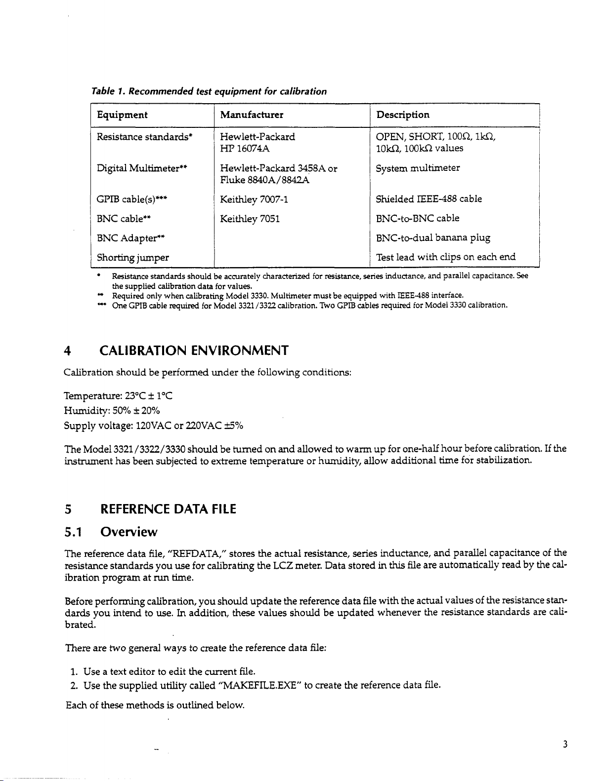
Table 1 summarizes recommended equipment for calibrating the Model
is
computer hardware, which
covered separately
in
paragraph
2.
3321/3322/3330.
your
particular set
in
a path specified by
is
run.
This
list does not include
this
file
Table
1.
Recommended test equipment for calibration
Equipment
Resistance standards*
Digtal Multimeter**
GPTB
cable(s)***
BNC cable**
Manufacturer
Hewlett-Packard
HP
16074A
Hewlett-Packard
Fluke
8840A/8842A
Keithley
Keithley
7007-1
7051
3458A
or
BNC Adapte?
Shorting jumper
Resistance standards should be accurately characterized for resistance,
the supplied calibration data for values.
*
Required only when calibrating Model 3330. Multimeter must be equipped with
**
One
GPIB
cable
4
requkd
CALIBRATION ENVIRONMENT
for Model 3321 /3322 calibration.
Two
GPIB
Calibration should be performed under the following conditions:
Temperature: 23°C
Humidity:
50%
Supply voltage: 12OVAC or 22OVAC
i
k
20%
1°C
*'/o
Description
OPEN,
lorn,
SHORT,
lOOkf2
loon,
values
System multimeter
Shielded
IEEE-488
cable
BNC-to-BNC cable
BNC-to-dual banana plug
Test lead with clips on each end
series
inductance, and parallel capacitance.
cables
reqd
IEEE-488
interface.
for Model 3330 calibration.
1w2,
See
The Model 3321/3322/3330 should be turned on and allowed to warm up for one-half hour before calibration.
instrument has been subjected to extreme temperature or humidity, allow additional time for stabilization.
5
5.1
The reference data file,
resistance standards you use for calibrating the LCZ meter. Data stored in
ibration program at
Before performing calibration, you should update the reference data file with the actual values
dards
REFERENCE DATA
Overview
"REFDATA,"
run
time.
you intend to use.
In
FILE
stores the actual resistance, series inductance, and parallel capacitance of the
this
file are automatically read by the
of
the resistance stan-
addition, these values should be updated whenever the resistance standards are cali-
brated.
two
There are
1.
Use a text editor to edit the current file.
general ways to create the reference data file:
2. Use the supplied utility called "MAKEFILE.EXE" to create the reference data file.
is
Each of these methods
outlined below.
If
the
cal-
3
5.2
Resistance standards values
Resistance standards values are supplied by the manufacturer on a calibration sheet.
will
value, both an inductance and capacitance value
be supplied.
be specified as a negative value. Similarly, the capacitance will be specified
inductive.
Any
negative capacitance or inductance value should be entered as 0 in the reference data file, asoutlined
If
the standard
is
capacitive, the inductance will
as
a
negative value
below.
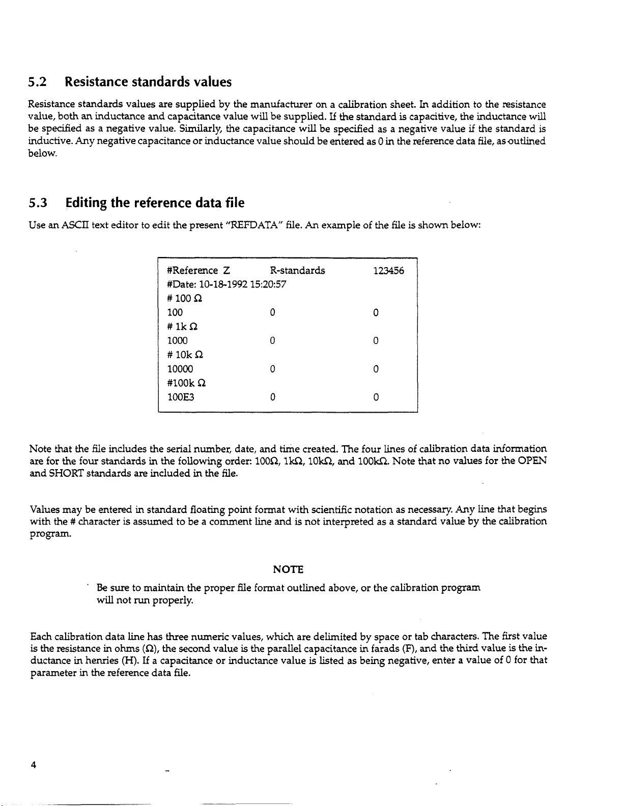
5.3
Use
Editing the reference data file
an
ASCII
text editor to edit the present
#Reference
#Date:
##
100
100
##
lk
n
1000
##
10k
10000
#look
~
100E3
10-18-1992
n
n
C.2
“REFDATA”
Z
R-standards
15:20:57
0
0
0
0
file.
An
example of the file is shown below:
123456
0
0
0
0
In
addition to the resistance
if
the standard
is
Note that the file includes the serial number, date, and time created. The four lines of calibration data information
are for the four standards in the following order:
and SHORT standards
are
included
in
the
file.
Values may be entered in standard floating point format with scientific notation as necessary.
with the
#
character
is
assumed to be a comment line and
100R,
1w1,1Ow1,
and
100W.
is
not interpreted as a standard value by the calibration
Note that no values for the
Any
line that begins
OPEN
program.
NOTE
’
l3e
sure
to maintain the proper file format outlined above, or the calibration program
will
not
run
properly.
Each calibration data line
is
the resistance
in
ohms
ductance in henries (H).
has
three
numeric values, which are delimited by space or tab characters. The first value
(n),
the second value
If
a capacitance or inductance value
is
the parallel capacitance in farads
is
listed
(F),
and the
as
being negative, enter a value of 0 for that
third
value
is
the
in-
parameter in the reference data file.
4
5.4
Using
the
MAKEFILE.EXE
utility
The preferred method to create the reference data file
to
use
this
utility
to create the reference data file.
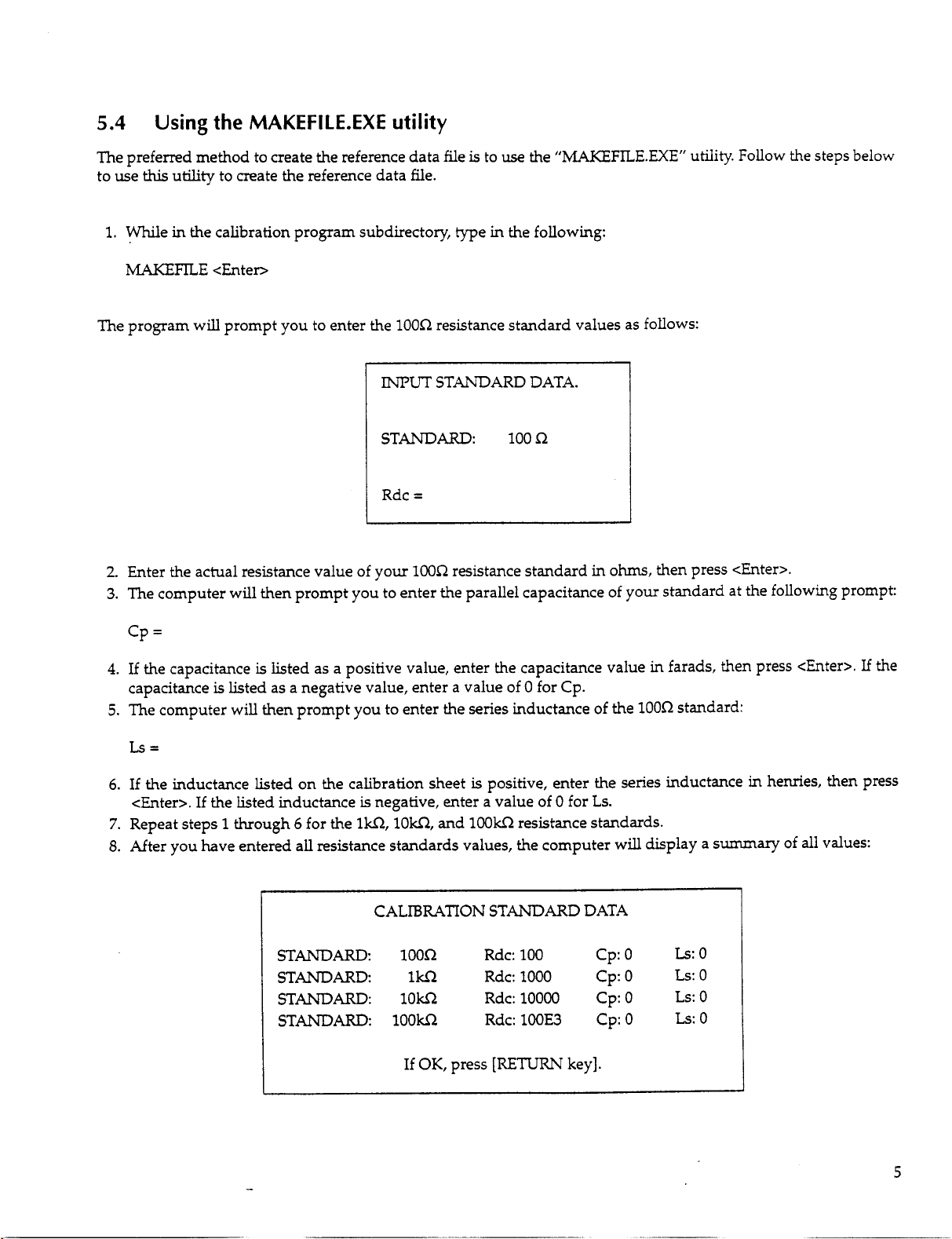
1.
While in the calibration program subdirectory, type
MAKEFILE
The program will prompt you to enter the
<Enten
lOOR
I"
STANDARD:
Rdc
=
2.
Enter the actual resistance value of
3.
The computer will then prompt you to enter the parallel capacitance of
your
lOOR
is
to
use
the
in
the following:
resistance standard values
STANDARD DATA.
100R
resistance standard
"MAKEFILE.EXE"
as
follows:
in
ohms,
then press <Enter>.
your
standard at the following prompt:
utility. Follow the steps below
cp
=
4.
If the capacitance
capacitance
5.
The computer will then prompt you to enter the series inductance of the
is
listed as a positive value, enter the capacitance value
is
listed as a negative value, enter a value of 0 for Cp.
Ls=
6.
If the inductance listed on the calibration sheet
<Enter>. If the listed inductance
7.
Repeat steps
8.
After
you
1
through
have entered all resistance standards values, the computer will display a
6
STANDARD:
STANDARD
STANDARD:
STANDARD:
for the 1w2,
is
negative, enter a value
lorn,
CALIBRATION STANDARD DATA
lOOR
1w2
low2
1OOw2
If
OK,
and
press
is
positive, enter the series inductance in henries, then press
of
0
for
lOOkR
resistance standards.
Rdc: 100
Rdc: 1000
Rdc:lOOOO
100E3
Rdc:
[RETURN
key].
Ls.
cp:o
cp:o
Cp:O
Cp:O
in
farads, then press <Enter>.
1000
standard:
summary
of
Ls:o
Ls:
0
Ls:O
Ls:O
all
values:
If
the
-
5

9.
Press <Enter>
through 6 above to re-enter values.
10.
After all values are entered
if
all values are correct, or press
any
other key to reenter standards values. Follow steps
and
accepted, the program will prompt you for the reference data filename:
1
STANDARD
File name ’refdata’.
[RETURN]
11.
Simply press <Enter> to use the default “REFDATA” filename, or press any other key, then enter the desired
filename at the prompt.
sponding environment data variable
12. Finally, enter the serial number of your standards set at the prompt, then press <Enter>. The reference data file
will then be saved
6
The following paragraphs will *take you through the procedure necessary to complete calibration of the Model
3321/3322/3330 LCZ Meter. Before performing calibration, you must have previously completed the following:
CALIBRATION PROCEDURE
Installed the calibration software (paragraph 2).
Installed and configured the computer
NOTE:
using
the selected filename, and the program
key to continue. Any other key to change filename
If
you use a filename other
in
FILE
NAME
than
“REFDATA,”
the calibration program. See paragraph 6 for details.
will
end.
IEEE-488
interface.
you
must also change the corre-
Setup the reference data file with the correct resistance standards values (paragraph
6.1
6.1.1
Before performing calibration, the Model 3321/3322/3330 must be connected to the
computer.
If’you
ure
Hardware preparation
Connections
Use
only a shielded
If
you are calibrating multiple units, connect
IEEE-488
one LCZ meter during a calibration session.
are
calibrating the Model 3330, connect the multimeter to the computer and the LCZ meter, as shown
1.
IEEE-488
bus at a time. Manually change bus connections when calibrating more than
cable such as the recommended Keithley Model 7007-1.
NOTE
only
one Model 3321/3322/3330 to the
GPIB
5).
(IEEE-488)
interface of the
in
Fig-
6

II
-
Model
332113322l3330
Figure
6.1.2
Connect
cable shell
~ ~~ ~
Digital
(HP3458A
7.
Calibration connections
Multirneter
or
Fluke
G
to
884ON42A)
Note
:
Multirneter is required
Model
as
display
Power-up procedure
b'
-&
LO
w'
shown
Y
Volts
3330
only
and
signal level (see text).
/
I
BNC
Input
L
BNC/Dual Banana Adapter
LCZ
only
Meter. Connect multirneter
when calibrating voltage
\
H
CUR
Cable
when calibrating
I
Cable
IBM
PC
AT
rl
I/
1.
Turn
on the LCZ meter. The instrument will begin its self-calibration cycle.
2.
The
3.
If
"EEEEE"
been detected, and calibration cannot be performed without clearing the error. Use the following procedure to
clear the error before performing calibration:
A.
B.
C. Connect one end of
D.
4.
After
DISPLAY will show "CAL," while the
and
"22222"
Leave the instrument tumed on with the "EEEEE" and
PLAY and the DISPLAY.
Remove the rubber plug that covers the access hole on the rear panel of the LCZ meter.
Momentarily touch the other end
the
"EEEEE
mode.
turning
22222"
on the power, allow a =-minute warm-up period before beginning the calibration procedure.
are displayed on the DISPLAY, a calibration constants error has
the
Adjust terminal
of
the probe
error message has been cleared. The instrument will then enter the normal measurement
@l
DISPLAY will count down to
DISPLAY and
shorting
probe
to
"22222"
to
the front panel G terminal, as
TPlOl
through the rear panel access hole, and venfy that
0.
messages still displayed on the
shown
in
/A]
Figure
DIS-
2.
7
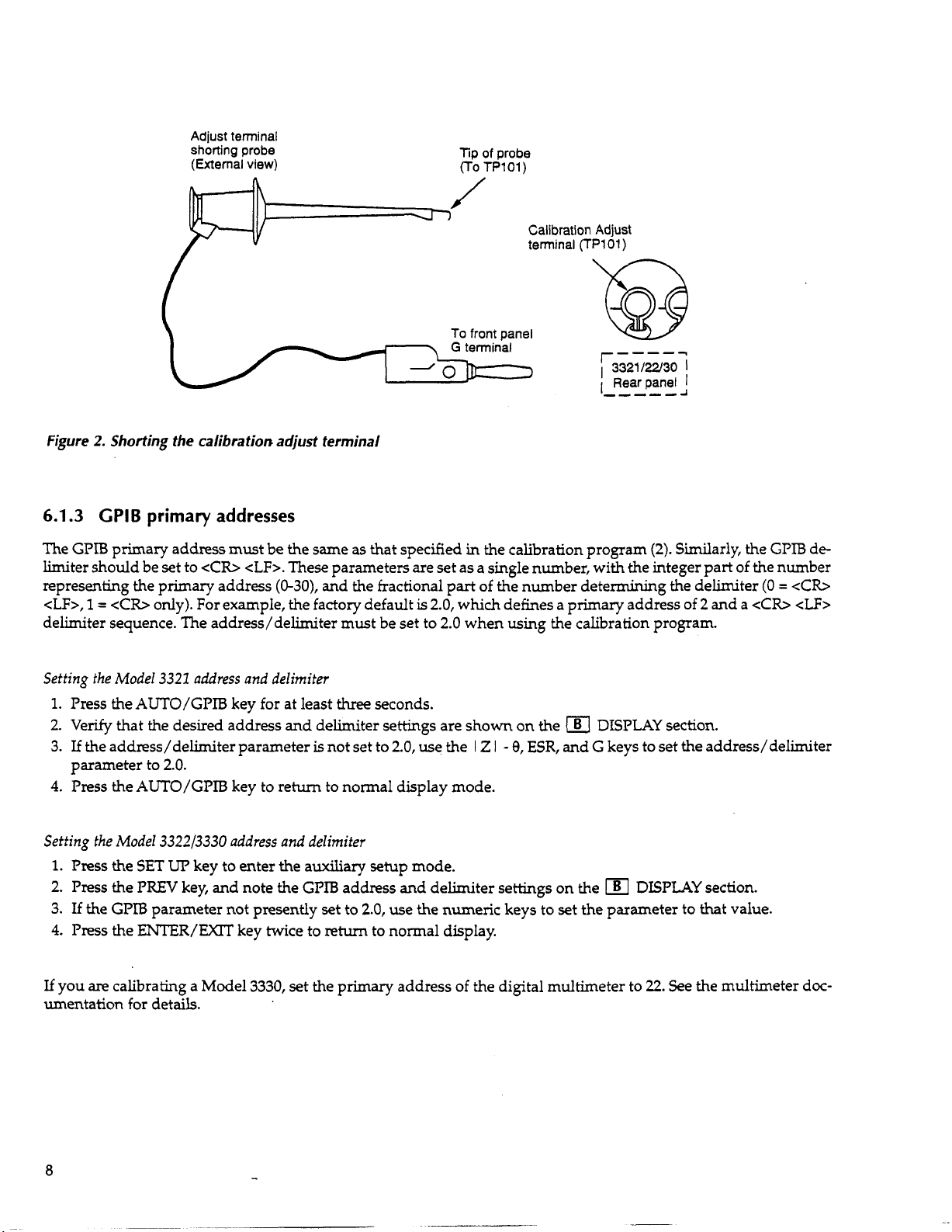
Adjust
terminal
shorting
(External
probe
view)
Tip
(To
of
probe
TP101)
Figure
2.
Shorting the calibration adjust terminal
6.1.3
The
limiter should be set to
representing the primary address (0-30), and the fractional
<U>,
delimiter sequence. The address/delimiter must be set to
Setting the Model 3321 address
1.
2.
3.
4.
GPlB
GPIB
1
=
Press the
Venfy that the desired address
If
the addxess/delimiter parameter
parameter to
Press the
primary addresses
primary address must be the same
<Cm
cLF>.
cCR>
only). For example, the factory default
and
delimiter
AUTO/GPIB
2.0.
AUTO/GPIB
key for at least
key to retum
as
that specified
These parameters are set as a single number, with the integer part of the number
is
2.0,
three
seconds.
and
delimiter settings are shown on the
is
not set to
to
normal display mode.
2.0,
use the
Calibration
terminal
Adjust
(TPlO1)
-----
r33211w30
Rearpanel
L,,--d
in
the calibration program
part
of the number determining the delimiter
which defines a primary address of 2 and
2.0
when using the calibration program.
le]
DISPLAY
I Z I - 9,
ESR,
and G keys to set the address/delimiter
I
I
(2).
Similarly, the
section.
GPTB
(0
=
a
<Cb
de-
<Cb
cLF>
Setting the Model 332213330 address and delimifer
1.
Press
the
SET
UP
key to enter the auxiliary setup mode.
2.
Press the
3.
If
the
4.
Press the
If
you
are
umentation for details.
8
PREV
key, and note the
GPIB
parameter not presently set to
ENTER/EXIT
calibrating a Model 3330, set the primary address of the digital multimeter to
key twice to return to normal display.
GPIB
address and delimiter settings on the
2.0,
use the numeric keys
to
set the parameter
DISPLAY
22.
section.
to
that value.
See the multimeter doc-

6.1.4 Calibration adjust terminal
TP101,
calibration.
6.2
which
1.
Remove the rubber plug that covers the rear panel access hole.
2.
Connect a
is
accessible through a hole in the rear panel, must be connected to the front panel G terminal
To
ground
clip
TPlOl,
lead or probe between
complete the following steps:
TPlOl
and the front panel G terminal as shown
Calibration program
in
Figure
6.2.1 Overview
The supplied calibration program
terface. The values of a set
and the correct values stored in the reference data file are calculated. Corrected data are then written to
LCZ
in the
Model
digital multimeter.
meter, and the instrument uses these corrected values during normal measurements.
3330
calibration includes
of
is
used
to
control the
resistance standards are measured, and the deviation between the measured values
an
additional procedure, which calibrates voltage display and signal level using
LCZ
meter to be calibrated from the
PC
over the
6.2.2 Running the calibration program
2.
RAM
during
GPIB
in-
located
a
To
run
the calibration program, change to the directory in which the calibration program
following:
CAL <Enter>
6.2.3 Main menu
When the calibration program
is
located, then type the
is
run,
the following main menu
will
appear on the computer screen:
-
9

Main Menu Screen
3321/3322/3330 Calibration System Ver.
Calibration Process
Save Environment Data
Manipulate Calibration Data
Qm
Key wait sound
Calibration Data PATH
ENVIRONMENT
I
All
menus in the calibration program are regular popup menus. Use the
which will be highhghted. Press the <Enter> key to select or edit
gram
entry
is
the ”Calibration Process” field.
<ARROW - Change Field> <CR - Select Field/Edit>
DATA
Reference Data
GPIB Board present
MULTMETERtype
1.00
(c
4)
FILENAME
(c
+)
(c
+)
four
arrow keys to select the current field,
a
given field. Note that the default field upon pro-
OFF
c:\cal\
refdata
NI-PCIIA
hp3458a
If
an
invalid key
ed), the computer will beep. Pressing <Enter> for the PATH and FEENAME fields in the
section will allow you to edit those fields as appropriate. Simply type
<Enter> key.
6.2.4
Briefly, the main menu selections perform the following operations.
Calibration Process
The “Calibration Process” menu selection begins the actual calibration procedure. Refer to paragraph 6.3
plete details on performing the calibration process procedure.
Save
This
field with the arrows keys
Main menu selections
Enuironmenf
menu selection allows you
Key wait sound: The sound generated while the computer
Calibration Data PATH: The path that describes the location of the reference data file. Recall that the reference
data file contains the actual values of the calibration standards.
is
pressed (for example, pressing left or right arrow while the “Calibration Process” field
ENVIRONMENT
in
the desired path or filename, then press the
Data
to
save environment data variables, which can be changed by selecting the desired
and
then pressing <Enter>. Program environment data variables include:
is
waiting for data during calibration.
is
selectDATA
for
com-

Reference Data FILENAME: The
h
file
is
for
”REFDATA”.
name
of the file that contains the resistance standards values. The default name
GPIB Board present: The field shows the type of GPIB board installed in the computer. The
and
interfaces are the Keithley KM-488-ROM
MLTL??METER
is
used
only when calibrating the Model 3330). The
Model
Environment variables are stored in the
Manipulate Calibration Data
This
computer screen. Refer
QUIT
Selecting
6.3
1.
To
play the following screen to remind you of the required 30-minute warm-up period:
358A
menu selection allows you to read and write the LCZ meter calibration table and display file contents on the
“QUIT”
Calibration
begin calibration, select “Calibration Process” on the main menu, then press <Enter>. The computer will
type:
’&IS
field identifies the type of d@al multimeter to be used for calibration
and the Fluke Model
to
paragraph
exits the calibration program and retums you to the
8840A/42A.
“SAVESET”
6.4
for complete information on data manipulation.
process
Calibration
the National Lnstruments
two
types of meters supported are the Hewlett-Packard
file located in the current directory
Process
Screen
DOS
[l]
PC-IIA
prompt.
boards.
two
supported GPIB
(a
multimeter
dis-
*******
Check that the environment temp.
Power-On all LCZ meters to be calibrated
3330
For
multimeter also.
Press
2.
If
you wish to continue calibration, press
3.
Next, the following screen
will
3321/3322/3330 Calibration System Ver.
CHECK
any
be displayed:
$******
is
23
i
1OC.
calibration, Power-On the ‘hp3458a’
key
to
continue
any
.......
key except
([ESC]
<<ABORT
<Ex>.
To
return to the main menu, press
1.00
>>)
<Esc>.
-
11

1
Calibration Process Screen
3321/3322/3330 Calibration System Ver.
CALIBRATE
[2]
QW
How many LCZ Meters? 3
1.00
Mad-une
Madrune 2 Serial
Machine 3 Serial
1
<ARROW - Change Field>
is
1,
The default number of LCZ meters
ing
the number of LCZ meters will affect the number of serial number fields that are displayed.
4.
After selecting the number
this
main menu at
5.
The next screen will remind
the calibration environment before calibration.
meters have been warming up for at least 30 minutes. Anegative response will cause the program
minute wait state (the program uses the
point, select
of
you
units,
"QUIT"
and you
select "CALIBRATE" to continue calibration.
instead.
that
all
LCZ meters should be allowed to warm up for at least 30 minutes
DOS
Calibration Process Screen
1
Serial
No.
00000
No.
00000
No.
00000
cCR
-
Select/Edit>
can
calibrate up to five units
The
screen
time function to time the length of the waiting period).
first prompts you as to whether or not the
in
a single calibration
If
you
wish to return to the
[3]
run.
to
go
Chang-
in
LCZ
to
a
30-
Note that the current
utes have elapsed,
12
3321 /3322/3330 Calibration System Ver.
Have machines been
30 minutes
Leave machine
before calibrating. ([ESC]
Current Tune
time
and remaining time values
the
next screen will be displayed.
(Y/N)
in
running
powered on state
cc
=
10:30:04
Remaining
will
be continuously updated while waiting. After
for at least
until
ABORT
>>)
=
1.00
10:59:54
00:29:50
30
min-

6. The next screen will remind you about
just terminal:
GPIB
connections, the primary address, and shorting the calibration ad-
I
CAUTION!!
Rear panel
Front panel : Set GPIB address and delimiter
Make sure that GPIB cable
,
7.
Make sure that calibration adjust terminal
Also
make sure the primary address/delimiter setting
8.
If you are calibrating a Model
monitor calibration of the Model
the digital multimeter
connected to the Model
is
3321/3322/3330
Calibration unit No. 1 Serial No. 123456
:
Connect the adjust cable between ADJ and
Press any key to continue
3330,
3330
turned on, and its primary address
3330,
as shown in Figure
Calibration Process
Calibration System Ver.
is
connected between the unit and PC
is
shorted and that the instrument
the next screen
LCZ Meter. Before continuing with
will
1.
.......
([ESC]
is
2.0.
guide you
Screen
[2.0]
cc
is
set to
[4]
1.00
ABORT
through
22.
Also
GND.
>>)
is
properly connected to the GPIB.
signal level calibration
ths
step, you should make sure
make sure that the multimeter
and
voltage
that
is
Calibration Process Screen [4a] (Model
3321/3322/3330
Calibrate the Frequency Response of the
monitor.
Calibrate the signal level of the
Calibrating the signal level.
Connect
The program will allow you to abort the process at various stages. Errors are reported at the bottom of the screen
to
prompt
you
regarding signal cable,
3330
Press
and 'hp3458a' multimeter
any
key to continue
GPIB
Calibration System Ver.
3330's
using
.......
([ESC]
address, etc.
3330.
.
.
SPECIAL
cc
ABORT
3330
1.00
voltage
Only)
JIG.
>>)
13

9.
Press any key except
connect standards using the following screen:
cEso
to continue with calibration.
During
calibration, the computer will prompt you
to
3321/3322/3330 Calibration System Ver.
Modek3321 Unit
Calibration Process Screen
No.
:3 Serial
No.:
123456 Sample Set: 2/2
[5]
1.00
any
Press
10.
During
the LCZ meter twice:
OPEN
SHORT
lOOR
These standards should be connected to the LCZ meter, as shown
tlu
part of the calibration process, you will be prompted
lki2
lOkS2
loom
key to continue
.......
([ESC]
cc
NOTE
Be
sure
to
connect the H and L terminals
LO terminals on the LCZ meter.
Do
not handle the standards excessively, or the resulting increase in temperature may
result
in
inaccurate calibration.
of
each standard to the corresponding
ABORT
>>)
to
connect each of the following standards to
in
Figure 3.
HI
and

IL
H
Standard Resistance
Figure
11.
12.
13. After calibrating the unit(s), the calibration data file is created and written to the computer disk
14.
3.
Calibration standards connections
After connecting each standard, press any key except
to abort the calibration process and return to the main menu.
If
you are calibrating more than one
directory. The filename for
seconds) when calibration
Example: 5/21/92 10:45:03
Filename: "05219210.450"
Values written to the file are
ment model number and serial number will also be written to the file.
When
all
units have been calibrated, the following message screen will be displayed:
this
is
performed.
in
unit,
file
is
derived from the
ASCII
representation
the process will be repeated for each unit.
Calibration Process Screen
3321/3322/3330 Calibration System Ver.
Check
sum
is
being written
<Ex>
to continue with calibration You
Dos
date (month/day/year) and time (hour/minutes/
of
double-precision floating-point numbers. The
[6]
...
can
1.00
press <Eso
in
the current
instru-
15.
Press
Finished calibration for 3 unit(s).
Press
any key to continue
any
key to re6 to
Calibration is now complete. However, new calibration constants do not
until
power
cessful.
the
main menu.
NOTE
is
cycled. See the following paragraph
.....
to
determine
go
into effect
if
calibration was suc-
15

6.3.1
Post calibration
After calibration
ber plug
strument oes through its power-up self-calibration cycle without errors.
on the
up calibration constants
Service Manual or the Model 3330 Service Manual for information on battery replacement and repair.)
To
manual.
6.4
Selecting “Manipulate Calibration Data’’ from the main menu will display the following screen and allow you to
perform the operations described below.
in
venfy calibration accuracy, perform the verification procedures described
Manipulate Calibration Data
has
been completed, remove the jumper clip connected between
the access hole.
and
@l
DISPLAY sections, repeat the calibration procedure.
RAM
I
TPlOl
and
G,
and install the rub-
Turn
off
the power for
may require replacement, or the unit may require repair. (See the Model 3321/3322
Manipulate Calibration Data Screen
3321/3322/3330 Calibration System Ver.
Directory
Write Machine Table
Read Machine Table
Type File
Listing
three
seconds, then
turn
the unit back on, and venfy that the in-
If
the errors
If
the error persists, the battery that backs
in
1.00
“EEEEE”
Section 1 of the respective service
and
“22222“
appear
SPECIFICATION
I
(ARROW
Direct0 y Listing
This
selection will allow you
lected, the program will display the following prompt for the directory
SPECIFICATION
Enter the desired path, then press <Enter>. The default path
Write Machine Table
This
menu selection writes calibration data from a given computer data file to Model 3321/3322/3330
this
menu item
16
>>
is
selected, the computer will prompt you for the name
to
-
-
display a listing of files
>>
-
Change Field>
<CR
-
Select/Edit>
in
a manner similar to the
to
be displayed:
is
the current directory,
of
the calibration data file as follows:
DOS
and
“DIR”
the output
command. When
is
paginated.
RAM.
When
se-

WRlTE
Machine Table FROM file name
>>
-
Type in the name of the file to be loaded, then press <Enter>. Alist of data sets with serial numbers
to
bers will be displayed on the screen. Eriter the number corresponding to the data set
3321 /3322/3330,
Read
Machine Table
This
menu selection reads the calibration table from the
this
item
is
READ
Type in the desired filename, then press <Enter>. The unit will then prompt for the serial number and model num-
ber:
Serial
NO. & Model Type
Type
in
the pertinent information, then
the data wlll be stored in the designated computer data file.
then press <Enter>.
NOTE
The Model
G)
to
ment
selected, the program will prompt you for the filename as follows:
Machine Table TO file name
3321/3322/3330
in
order to write calibration data to the instrument.
is
connected to the
>>
-
must be
GPIB
>>
-
press
in
the calibration adjust mode
interface of the computer.
LCZ
meter and stores data
<Enter>. The calibration table will be read from the instrument, and
Also
be
(-101
sure
be written to the Model
connected
that the
in
a designated disk file. When
and
instru-
model num-
Type File
This
menu selection allows you
item
is
selected, the instrument will prompt you for the name of the
FILESPEC
Type in the name of the file, then press <Enter>. The display will be paginated
>>
-
to
display the contents of a designated
ASCII
file:
QUfl
Selecting
QUIT
will return you to the main menu screen of the calibration program.
file on the computer screen. When
if
necessary.
this
 Loading...