

Page 1

DEPARTMENT OF THE ARMY TECHNICAL BULLETIN
CALIBRATION PROCEDURE FOR
OSCILLOSCOPE,
TEKTRONIX TYPES 317 (AN/USM-154)
AND RM17
Headquarters, Department of the Army, Washington, DC
22 September 1975
TB 9-6625-1172-35, 30 August 1974, is changed as follows:
TB 9-6625-1172-35
Change 1
The title is changed as shown above.
1. Remove old pages and insert new pages as indicated below. New or changed material is
indicated by a vertical bar in the margin of the page.
Remove pages Insert Pages
1 through 6 1 through 6
2. File this change sheet in front of the publication for reference purposes.
By Order of the Secretary of the Army:
FRED C. WEYAND
General, United States Army
Official: Chief of Staff
PAUL T. SMITH
Major General, United States Army
The Adjutant General
Distribution:
To be distributed in accordance with DA Form 12-34A (qty rqr block No. 75), requirements
for Calibration Procedures Publications.
This publication is a courtesy quick copy from the UNITED
STATES ARMY ADJUTANT GENERAL PUBLICATIONS
CENTER, ST. LOUIS, MISSOURI, to meet your needs while we
are replenishing our regular stock.
Page 2

TB 9-6625-1172-35
10. Crt Geometry and Astigmatism graticule line.
fig. 2) until markers are parallel with vertical
a. Performance Check
(1) Connect time-mark generator (A6) to TI
VERTICAL INPUT, using cable (B5) and if necessary,
adapter (B2). Adjust time-mark generator for .1 mS
marker output.
(2) Adjust TI POSITIONING controls to aline
top of markers with top horizontal graticule line and
extending across full horizontal range of crt. If markers
displayed on crt are not parallel with vertical graticule
lines, perform b(l) below.
(3) Reposition TI waveform to display both
the baseline and markers. If sharp focus of crt display
cannot be obtained by adjusting front panel FOCUS
control, perform b(2) below.
b. Adjustments
Table 4. Calibrator Accuracy
Test Instrument Ac/Dc Voltmeter Indications
VOLTS PEAK-TO-PEAK
Switch Settings. Min Max
in conjunction with FOCUS control for sharpest focus of
displayed baseline and markers.
11. Calibrator Accuracy
position) and remove V875 (fig. 3), or for TI's with S/N
280 and above V883 (fig. 3) (V573, fig. 4).
CAL OUT connector and chassis ground, using leads
supplied with ac/dc voltmeter and, if necessary, adapter
(B 1).
(1) Adjust R861 (fig. 1) (GEOM ADJ R861,
(2) Adjust R860 (fig. 1) (ASTIG R856, fig. 2)
a. Performance Check
(1) Turn TI POWER switch to off (down
(2) Turn TI POWER switch to ON.
(3) Connect ac/dc voltmeter (A2) between TI
(vdc).
50 48.5 51.5
20 19.4 20.6
10 9.7 10.3
5 4.85 5.15
2 1.94 2.06
1 0.97 1.03
.5 0.485 0.515
.2 0.194 0.206
.1 0.097 0.103
.05 0.0485 0.0515
(4) Turn TI VOLTS PEAK-TO-PEAK switch (6) Turn TI POWER switch to off (down) and
to 100. If ac/dc voltmeter does not indicate bet- replace vacuum tube removed in (1) above.
ween 97 and 103 volts dc, perform b below. (7) Turn TI POWER switch to ON and VOLTS
PEAK-TO-PEAK switch to OFF.
(5) Repeat technique of(4) above for settings b. Adjustments. Adjust CAL ADJ R879 (fig. 3)
and indications listed in table 4. Ac/dc voltmeter. (CAL. ADJ. R566, fig. 4) for a 100-volt dc indicawill indicate within limits specified. tion on ac/dc voltmeter (R).
¶¶ U.S. GOVERNMENT PRINTING OFFICE: 19754656681174
6
Page 3

DEPARTMENT OF THE ARMY TECHNICAL BULLETIN
CALIBRATION PROCEDURE FOR
OSCILLOSCOPE,
TEKTRONIX TYPES 317 AND RM17
Headquarters, Department of the Army, Washington, D.C.
30 August 1974
SECTION I. IDENTIFICATION AND DESCRIPTION
Test instrument identification ------------------------------------------------------------------- 1 2
Calibration data card, DA Form 2416--------------------------------------------------------- 2 2
Reporting of errors ---------------------------------------------------------------------------------- 3 2
Calibration description ----------------------------------------------------------------------------- 4 2
II. EQUIPMENT REQUIREMENT FOR OSCILLOSCOPE, TEKTRO -
NIX TYPES 317 AND RM17 (A-LEVEL)
Equipment required --------------------------------------------------------------------------------- 5 3
Accessories required ------------------------------------------------------------------------------- 6 3
III. PRELIMINARY OPERATIONS FOR OSCILLOSCOPE, TEKTRO-
NIX TYPES 317 AND RM17 (A-LEVEL)
Preliminary instructions --------------------------------------------------------------------------- 7 5
Equipment setup ------------------------------------------------------------------------------------- 8 5
IV. CALIBRATION PROCESS FOR OSCILLOSCOPE, TEKTRONIX
TYPES 317 AND RM17 (A-LEVEL)
Crt mechanical alinement ------------------------------------------------------------------------- 9 5
Crt geometry and astigmatism ----------------------------------------------------------------- 10 6
Calibrator accuracy --------------------------------------------------------------------------------- 11 6
Vertical dc balance ---------------------------------------------------------------------------------- 12 7
Vertical amplifier and preamplifier gain, attenuation, and stability --------------- 13 8
Attenuator compensation ------------------------------------------------------------------------- 14 11
Sweep triggering -------------------------------------------------------------------------------------- 15 12
Magnifier gain and registration ----------------------------------------------------------------- 16 12
Horizontal amplifier and sweep length ------------------------------------------------------ 17 13
Sweep timing ------------------------------------------------------------------------------------------- 18 13
Rise time ------------------------------------------------------------------------------------------------ 19 14
Power supply ------------------------------------------------------------------------------------------- 20 14
Final procedure --------------------------------------------------------------------------------------- 21 15
V. EQUIPMENT REQUIREMENTS FOR OSCILLOSCOPE, TEK-
TRONIX TYPE 317 (C-LEVEL)
Equipment required --------------------------------------------------------------------------------- 22 15
Accessories required ------------------------------------------------------------------------------- 23 16
VI. PRELIMINARY OPERATIONS FOR OSCILLOSCOPE, TEKTRO-
NIX TYPE 317 (C-LEVEL)
Preliminary instructions --------------------------------------------------------------------------- 24 17
Equipment setup ------------------------------------------------------------------------------------- 25 17
*TB 9-6625-1172-35
Paragraph Page
*This bulletin supersedes TB 9-6625-787-50, 8 December 1969, and TB 9-6625-1172-50, 31 May 1968., including all
changes.
1
Page 4

VII. CALIBRATION PROCESS FOR OSCILLOSCOPE, TEKTRONIX
TYPE 31 7 (C-LEVEL)
Calibrator ----------------------------------------------------------------------------------------------- 26 17
Crt alinement ------------------------------------------------------------------------------------------ 27 18
Crt astigmatism --------------------------------------------------------------------------------------- 28 18
Crt geometry ------------------------------------------------------------------------------------------- 29 18
Sweep triggering ------------------------------------------------------------------------------------- 30 19
Magnifier gain ----------------------------------------------------------------------------------------- 31 20
Horizontal amplifier gain -------------------------------------------------------------------------- 32 20
Sweep length ------------------------------------------------------------------------------------------ 33 20
Magnifier registration ------------------------------------------------------------------------------- 34 20
1 µSEC sweep timing ------------------------------------------------------------------------------ 35 20
10 µSEC/DIV sweep timing ---------------------------------------------------------------------- 36 21
2 µSEC/DIV linearity ------------------------------------------------------------------------------- 37 21
.5 µSEC/DIV sweep timing ----------------------------------------------------------------------- 38 21
.2 µSEC/DIV linearity ------------------------------------------------------------------------------ 39 21
.04 µSEC/DIV sweep timing and linearity -------------------------------------------------- 40 21
Variable attenuator balance --------------------------------------------------------------------- 41 22
Amplifier gain and attenuation ------------------------------------------------------------------ 42 23
Attenuator high-frequency compensation -------------------------------------------------- 43 23
Attenuator input capacitance -------------------------------------------------------------------- 44 23
Preamplifier low-frequency compensation ------------------------------------------------- 45 24
Delay line high-frequency response ---------------------------------------------------------- 46 24
Amplifier bandwidth---------------------------------------------------------------------------------- 47 25
Preamplifier bandwidth ---------------------------------------------------------------------------- 48 26
Power supply ------------------------------------------------------------------------------------------- 49 26
Final procedure --------------------------------------------------------------------------------------- 50 27
TB 9-6625-1172-35
Paragraph Page
IDENTIFICATION AND DESCRIPTION
1. Test Instrument Identification
This bulletin provides instructions for the A-level
calibration of Oscilloscope, Tektronix Types 317 and
RM17 and C-level calibration of Oscilloscope, Tektronix
Type 317. The manufacturer's instruction manuals were
used as the prime data source in compiling these
instructions. The oscilloscope will be referred to as the
"TI" (test instrument) throughout this bulletin.
a. Model Variations. Type RM17 is the
rackmounted version of type 317. Wherever difference
exists between types, adjustments and parameters for
type 317 are listed in parenthesis for A-level calibration.
b. Time and Technique. The time required for this
calibration is approximately 3 hours, using the dc and
low frequency technique.
2. Calibration Data Card, DA Form 2416.
a. Forms, records, and reports required for
calibration personnel at all levels are prescribed by
TM 38-750. DA Form 2416 must be annotated
SECTION I
in accordance with TM 38-750 for each calibration
performed.
b. Adjustments to be reported on DA Form 2416
are designated (R) at the end of the sentence in which
they appear. When adjustments are in tables, the (R)
will follow the designated adjustment. Report only those
adjustments made and designated with (R).
3. Reporting of Errors
The reporting of errors, omissions, and
recommendations for improving this publication by the
individual user is encouraged. Reports should be
submitted on DA Form 2028, Recommended Changes
to Publications, and forwarded direct to Commander,
U.S. Army Missile Command, ATTN: AMSMI-MFPA,
Redstone Arsenal, AL 35809.
4. Calibration Description
TI parameters and performance specifications which
pertain to this calibration are listed in table 1.
2
Page 5

Table 1. Calibration Description
Test Instrument Parameters Performance Specifications
Power input requirements 115 vac ±10% (or 230 vac +10%), 50 to 60 Hz, 200 w
Calibrator:
Output 6.05 to 100 v p-p in 11 steps
Accuracy
Waveform
1
±3%
Square waves at approx 1 kHz
Vertical deflection system:
Deflection factor 0.01 to 50 v/cm p-p in 12 steps; 0.1 to 50 v/cm dc coupled
and 0.01 v/cm to 50 v/cm ac coupled.
Accuracy
±3%
Frequency response Dc to 10 MHz; 0.1 to 50 v/cm, dc coupled; 2 Hz to 10 MHz,
0.1 to 50 v/cm, ac coupled; 2 Hz to 9 MHz, 0.01 to 0.05
v/cm, ac coupled.
1 megohm, 38 pf, direct connection
Input impedance
1
Rise time 35 nsec
TB 9-6625-1172-35
Horizontal deflection system:
Deflection factor
1
Approx 1.3 v/cm
Frequency response Dc to 500 kHz
Sweep speeds:
Time base
0.2 µAsec/cm to 2 sec/cm, in 22 steps; 5X magnifier extends
fastest sweep rate to 0.04 µsec/cm.
1
This specification Is for information only and is not verified in this bulletin.
SECTION II
EQUIPMENT REQUIREMENTS FOR OSCILLOSCOPE,
TEKTRONIX TYPES 317 and RM17
(A-LEVEL)
5. Equipment Required
listed in table 2 provide a four-to-one ratio between the
standard and TI. Where the four-to-one ratio cannot be
Table 2 identifies the specified equipment used for A-
level calibration. This equipment is issued with the
met, the actual accuracy of the equipment selected is
shown in parenthesis.
secondary transfer calibration standards set and is to be
used in performing this procedure. Alternate items may
6. Accessories Required
be used by the calibrating activity when the equipment
listed in table 2 is not available. The items selected
must be verified to perform satisfactorily prior to use and
must bear evidence of current calibration. The
equipment must meet or exceed the minimum use
specifications listed in table 2. The accuracies
The accessories listed in table 3 are issued with the
secondary transfer calibration standards set and are to
be used for A-level calibration. When necessary, these
items may be substituted by equivalent items unless
specifically prohibited.
3
Page 6

TB 9-6625-1172-35
Table 2. Minimum Specifications of Equipment Required
Item Common Name Minimum Use Specifications Manufacturer, Model, and Part Number
A1 AC CALIBRATOR Range: 13.7158 my rms to Hewlett-Packard, Model
72.826 v rms at 1 kHz. 745A (MIS-10342).
Accuracy: ±0.75%
A2 AC/DC VOLTMETER Range: -153 to +309 vdc Dana, Model 5703-S-2127
(7912606).
Accuracy: ±0.75%
A3 AUTOTRANSFORMER Range: 105 to 125 vac General Radio, Model
W10MT3AS3 (7910809).
Accuracy: ±0.75%
A4 DC VOLTMETER Range: -1261 to -1339 vdc Electrical Instruments Ser-
vice, Model ESV (MIS-10276).
Accuracy: ±0.75%
A5 SQUARE-WAVE Range: 50 Hz to 1 MHz Tektronix, Type 106
GENERATOR. (MIS-10284).
Rise Time: Less than 35 nsec
A6 TIME-MARK GENERATOR Range: 20 nsec to 1 sec Tektronix, Type 184MOD
markers. 146B (7912042-2).
Accuracy: ±0.75%
Table 3. Accessories Required
Item Common Name Description and Part Number
B1 ADAPTER BNC plug to double banana posts (7909401)
B2 ADAPTER BNC jack to UHF plug (10519439)
B3 ADAPTER UHF jack to BNC plug (8109698)
B4 CABLE 36-in., RG-580/U; BNC plug and double banana plug termina-
tions (7907471).
B5 CABLE 30-in., RG-580/U; BNC plug terminations (7907467)
B6 CAPACITANCE 5 to 80 pf, variable (SKD-4850-44)
STANDARDIZER.
B7 LEAD 24-in., No. 18 AWG; single banana plug terminations (red)
(7907497).
B8 LEAD 24-in., No. 18 AWG; single banana plug terminations (black)
(7907498).
B9 PROBE Test hook, banana plug to miniature hook (SKC-4850-14)
4
Page 7

SECTION III
PRELIMINARY OPERATIONS FOR OSCILLOSCOPE,
TEKTRONIX TYPES 317 AND RM17 (A-LEVEL)
TB 9-6625-1172-35
7. Preliminary Instructions
a. The instructions outlined in this section are
preparatory to the calibration process. Personnel should
become familiar with the appropriate sections before
beginning the calibration.
b. Items of equipment used in this procedure are
referenced within the text by common name and item
identification number as listed in tables 2 and 3. For the
identification of equipment referenced by item numbers
prefixed with A, see table 2, and for prefix B, see table 3.
WARNING
HIGH VOLTAGE is used during the
performance of this calibration.
DEATH ON CONTACT may result if
personnel fail to observe safety
precautions.
8. Equipment Setup
a. Remove protective cover from TI.
b. Connect TI to autotransformer (A3).
c. Connect autotransformer to 115-volt
SECTION IV
ac source and adjust controls for 115 volts ac.
d. Position TI controls as listed in (1) through (15)
below:
(1) INTENSITY control to midrange.
(2) FOCUS control to midrange.
(3) CALIBRATOR switch to OFF.
(4) HORIZONTAL DISPLAY switch to NORM.
(5) TRIGGER SELECTOR switch (black) to
+INT.
(6) TRIGGER SELECTOR switch (red) to
AUTO.
(7) TRIGGERING LEVEL control to 0 (zero).
(8) STABILITY control fully clockwise.
(9) TIME/DIV switch to .1 MILLISEC.
(10) VARIABLE TIME/DIV control to
CALIBRATED.
(11) VERTICAL POSITIONING control to
midrange.
(12) HORIZONTAL POSITIONING control to
midrange.
(13) VOLTS/DIV switch to .1.
(14) VARIABLE VOLTS/DIV control to
CALIBRATED.
(15) AC DC switch to AC.
e. Turn POWER switch to ON and allow sufficient
time for equipment to warm up and stabilize.
NOTE
Unless otherwise specified, verify the
results of each test and take
corrective action whenever the test
requirement is not met before
continuing with the calibration.
NOTE
When indications specified in
paragraphs 9 through 19 are not
within tolerance, perform the power
supply check prior to making
adjustments. After adjustments are
made, repeat paragraphs 9 through
19, Do not perform power supply
check if all other parameters are
within tolerance.
9. Crt Mechanical Alinement
a. Performance Check
(1) Position TI controls as listed in (a) through
(c) below:
(a) SCALE ILLUM control as desired.
CALIBRATION PROCESS FOR OSCILLOSCOPE,
TEKTRONIX TYPES 317 AND RM17 (A-LEVEL)
(b) INTENSITY and FOCUS controls for
sharp trace.
(c) HORIZONTAL POSITION control
for start of trace at left edge of graticule.
(2) Adjust VERTICAL POSITION control for
start of trace alined with center horizontal graticule line.
If end of trace is not within M small division of center
horizontal graticule line, perform b below.
b. Adjustments
WARNING
HIGH VOLTAGE is present in area of
crt base; use extreme caution when
making the following adjustments.
(1) Loosen crt base clamp and rotate crt with
positioning handle for indication as specified in a(2)
above.
(2) Tighten crt base clamp and repeat a(2)
above.
5
Page 8

TB 9-6625-1172-35
10. Crt Geometry and Astigmatism
fig. 2) until markers are parallel with vertical graticule
a. Performance Check
(1) Connect time-mark generator (A6) to TI
VERTICAL INPUT, using cable (B5) and if necessary,
adapter (B2). Adjust time-mark generator for .1 mS
marker output.
(2) Adjust TI POSITIONING controls to aline
top of markers with top horizontal graticule line and
extending across full horizontal range of crt. If markers
displayed on crt are not parallel with vertical graticule
lines, perform b(1) below.
(3) Reposition TI waveform to display both
the baseline and markers. If sharp focus of crt display
cannot be obtained by adjusting front panel FOCUS
control, perform b(2) below.
b. Adjustments
Table 4. Calibrator Accuracy
Test Instrument Ac/Dc Voltmeter Indications
VOLTS PEAK-TO-PEAK
Switch Settings. Min Max
line.
in conjunction with FOCUS control for sharpest focus of
displayed baseline and markers.
11. Calibrator Accuracy
position) and remove V875 (fig. 3), or for TI's with SIN
280 and above V883 (fig. 3) (V573, fig. 4).
CAL OUT connector and chassis ground, using leads
supplied with ac/dc voltmeter and, if necessary, adapter
(B1).
(1) Adjust R861 (fig. 1) (GEOM ADJ R861,
(2) Adjust R860 (fig. 1) (ASTIG R856, fig. 2)
a. Performance Check
(1) Turn TI POWER switch to off (down
(2) Turn TI POWER switch to ON.
(3) Connect ac/dc voltmeter (A2) between TI
(vdc).
50 48.5 51.5
20 19.4 20.6
10 9.7 10.3
5 4.85 5.15
2 1.94 2.06
1 0.97 1.03
.5 0.485 0.515
.2 0.194 0.206
.1 0.097 0.103
.05 0.0485 0.0515
(4) Turn TI VOLTS PEAK-TO-PEAK switch to
100. If ac/dc voltmeter does not indicate between 97
and 103 volts dc, perform b below.
(5) Repeat technique of (4) above for settings
and indications listed in table 4. Ac/dc voltmeter will
indicate within limits specified.
(6) Turn TI POWER switch to off (down) and
replace vacuum tube removed in (1) above.
(7) Turn TI POWER switch to ON and VOLTS
PEAK-TO-PEAK switch to OFF.
b. Adjustments. Adjust CAL ADJ R879 (fig. 3)
(CAL. ADJ. R566, fig. 4) for a 100-volt de indication on
ac/dc voltmeter (R).
6
Page 9
TB 9-6625-1172-35
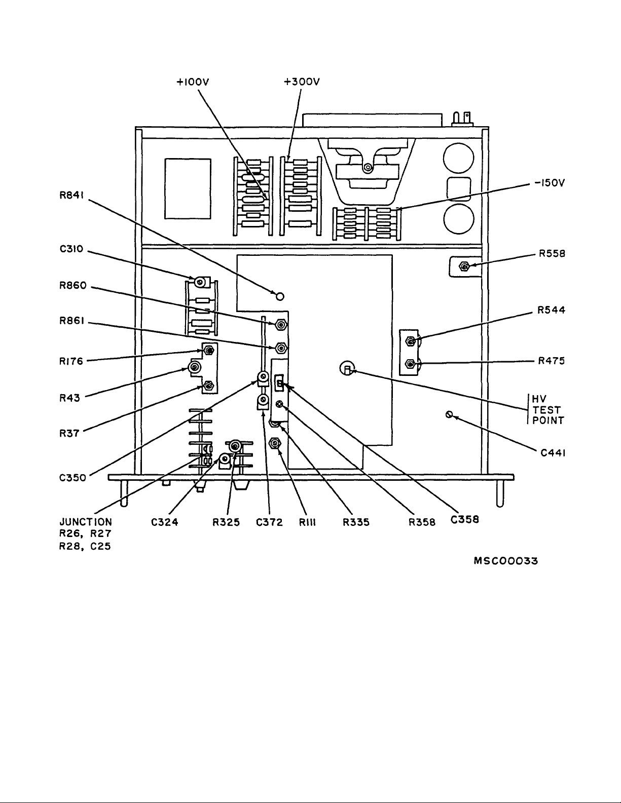
Figure 1. Oscilloscope-bottom view (type RM17).
12. Vertical Dc Balance
a. Performance Check
(1) Connect TI VERTICAL INPUT to chassis
ground, using lead (B 7), and if necessary, adapter (B1).
(2) Position TI controls as listed in (a) through
(c) below:
(a) AC/DC switch to DC.
(b) STABILITY control fully clockwise.
(c) VERTICAL POSITION control to
aline trace behind horizontal graticule center line.
(3) Turn VARIABLE VOLTS/DIV control from
fully clockwise to fully counterclockwise
7
Page 10
TB 9-6625-1172-35
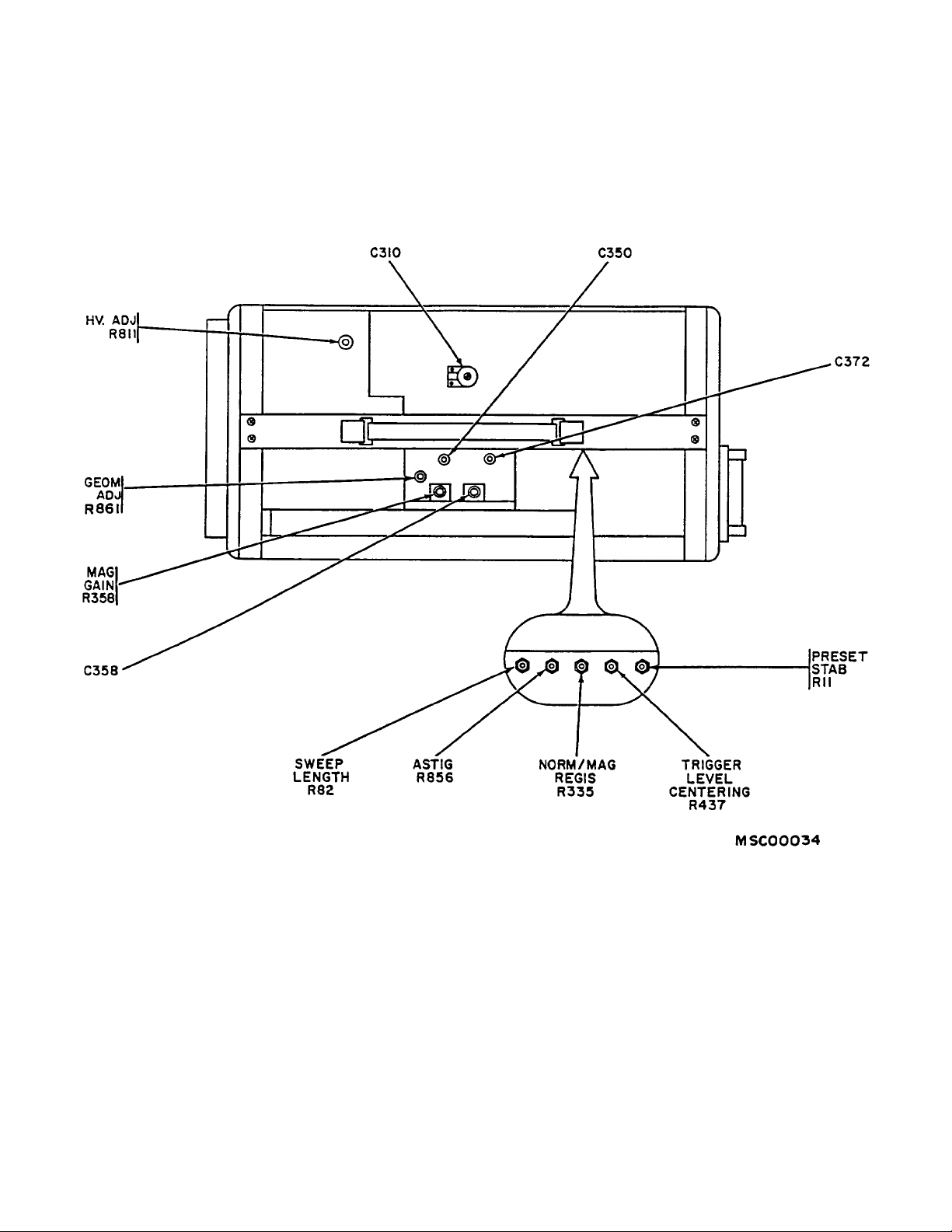
Figure 2. Oscilloscope - top view (type 317).
position. If trace does not remain behind center
horizontal graticule line, perform b below.
b. Adjustments. Adjust VARIABLE ATTEN. BAL.
(front panel) for minimum vertical movement of trace
while turning VARIABLE VOLTS/DIV control throughout
its range.
13. Vertical Amplifier and Preamplifier Gain,
Attenuation. and Stability
8
a. Performance Check
(1) Connect ac calibrator (Al) output to TI
VERTICAL INPUT, using cable (B4) and, if necessary,
adapter (B2).
(2) Turn TIME/DIV switch to 1 mSEC and
VARIABLE VOLTS/DIV switch to CALIBRATED.
Page 11

TB 9-6625-1172-35
(3) Adjust ac calibrator for 1 kHz and
amplitude for 4 major divisions of vertical deflection on TI
crt. If ac calibrator does not indicate between 137.158
and 145.642 millivolts rms, perform b(1) below.
(4) Turn VOLTS/DIV switch to .01 and adjust
ac calibrator for 4 major divisions of vertical deflection on
TI crt. If ac calibrator does not indicate
between 13.7158 and 14.5642 millivolts rms, perform
b(2) below.
(5) Vary autotransformer (A3) between 105
and 125 volts. Ac calibrator will remain between limits
specified in (4) above.
(6) Adjust autotransformer for 115 volts.
(7) Repeat technique of (4) above, using
settings listed in table 5. Ac calibrator will indicate
between limits specified.
Figure 3. Oscilloscope-top Mew (type RM17).
9
Page 12

Table 5. Vertical Amplifier and Preamplifier Gain and Attenuation
Test Instrument Ac/Dc Voltmeter Indications
VOLTS/DIV (vdc).
Switch Settings.
Min Max
.02 27.4316 mv 29.1284 mv
.05 68.579 mv 72.821 mv
.2 274.316 mv 291.284 mv
.5 685.79 mv 728.21 mv
1 1.37158 v 1.45642 v
2 2.74316 v 2.91284 v
5 6.8579 v 7.2821 v
10 13.7158 v 14.5642 v
20 27.4316 v 29.1284 v
50 68.579 v 72.821 v
TB 9-6625-1172-35
b. Adjustments
(1) Adjust ac calibrator for 141.4 millivolts rms
output. Adjust R544 (fig. 1) (GAIN ADJ R244, fig. 5) for
4 major divisions of vertical deflection on crt (R).
(2) Adjust ac calibrator for 14.14 millivolts rms
output. Adjust PREAMP GAIN ADJ R454 (fig. 3)
(PREAMP GAIN ADJ R154, fig. 5) for 4 major divisions
of vertical deflection crt (R).
10
Figure 4. Oscilloscope - right-side view (type 317).
Page 13

TB 9-6625-1172-35
14. Attenuator Compensation
a. Performance Check
(1) Connect square-wave generator (A5) to TI
INPUT, using cable and termination supplied with
square-wave generator, and adapter and capacitance
standardizer (B2 and B6) and, if necessary, adapter
(B3).
(2) Turn TI VOLTS/DIV switch to .01 and
TIME/DIV switch to .5 MILLISEC.
and amplitude for approximately 4 major divisions of
vertical display on TI cit.
optimum square-wave display on TI crt.
VOLTS/DIV switch setting listed in table 6. If square
wave displayed on TI crt does not have flat tops and
square corners, perform the appropriate adjustments
(3) Adjust square-wave generator for 1 kHz
(4) Adjust capacitance standardizer for
(5) Repeat technique of (3) above for each
listed in table 6.
Table 6. Attenuator Compensation Adjustments
Test Instrument Adjustments (fig. 3 or 5)
VOLTS/DIV Flat Top Square Corner
Switch Settings.
.2 C430 (C130) (R) C432 (C132) (R)
.5 C424 (C124) (R) C426 (C126) (R)
1 C416 (C116) (R) C418 (C118) (R)
10 C410 (C110) (R) C412 (C112) (R)
.02 C441 1 (R) ---
2
.05
1
Refer to figure 1 for location.
2
Turn TI TIME/DIV switch to 5 mSEC and adjust square-wave generator to 50 Hz.
R475 1 (R175) (R) ---
Figure 5. Oscilloscope-left-side view (type 317).
11
Page 14

TB 9-6625-1172-35
b. Adjustments. No further adjustments can be
made.
15. Sweep Triggering
a. Performance Check
(1) Connect CAL OUT to VERTICAL INPUT,
using lead (B7) or cable (B5).
(2) Position TI controls as listed in (a) through
(e) below:
(a) TRIGGER SELECTOR switch (red)
to AC.
(b) TIME/DIV switch to .5 MILLISEC.
(c) VOLTS/DIV switch to 1.
(d) VOLTS PEAK-TO-PEAK switch to
.5.
(e) STABILITY switch to PRESET.
(3) Connect junction of R26, R27, R28, and
C25 (fig. 1) (or R426 and R427, fig. 4) to chassis ground,
using probe (B9).
(4) Adjust VOLTS/DIV VARIABLE control for
1 minor division of vertical deflection on TI crt.
(5) Position crt trace on horizontal graticule
center line.
(6) Alternately switch TI TRIGGER
SELECTOR (black) control back and forth from +INT to INT. If sweep does not have stable triggering in both
+INT and -INT positions, perform 6(1) through (3) below.
(7) Remove short connected in (3) above.
(8) Turn TI TRIGGERING LEVEL control to
position where stable triggering occurs in both +INT and
-INT positions. If stable triggering does not occur when
TRIGGERING LEVEL control is in 0 (zero) position,
perform b(4) below.
(9) Turn TI TRIGGERING SELECTOR (red)
switch to DC.
(10) It may be necessary to adjust TI
VERTICAL POSITIONING control until sweep appears
on crt.
(11) Adjust VOLTS/DIV VARIABLE control for
1.5 minor divisions of vertical display on TI crt. If crt
display is not positioned at the center horizontal graticule
line, while TI TRIGGER SELECTOR (black) switch is
turned from +INT to -INT, perform b(5) below.
(12) Turn TI VOLTS PEAK-TO-PEAK switch to
OFF.
(13) Remove lead (B7) or cable (B5)
connected in (1) above.
(14) Turn TI TRIGGER SELECTOR (red)
switch to AUTO. IF stable waveform does not occur,
perform b(6) through (8) below.
b. Adjustments
(1) Adjust TI TRIGGER LEVEL CENTERING
R37 (fig. 1) (R437, fig. 2) until stable triggering is
obtained in both +INT and -INT positions.
12
(2) Reduce amplitude of crt display, using
VOLTS/DIV VARIABLE control until display becomes
unstable. Adjust R43 (fig. 1) on TI's with S/N 203 and
above (TRIGGER SENSITIVITY ADJ. R443, fig. 4) until
stable triggering is obtained in both +INT and -INT
positions.
(3) Repeat (1) and (2) above until no further
adjustments are required.
(4) Loosen setscrew on TRIGGERING
LEVEL knob and adjust to 0 (zero) position without
turning potentiometer shaft. Tighten setscrew.
NOTE
Do not disturb setting of
TRIGGERING LEVEL control
established in a(8) above.
(5) Adjust R558 (fig. 1) (INT TRIG DC LEVEL
ADJ R258, fig. 5) in conjunction with VERTICAL
POSITIONING control until sweep is positioned at center
horizontal graticule line as TRIGGER SELECTOR
(black) switch is turned from -INT to +INT.
(6) Turn R111 (fig. 1) (PRESET STAB R11,
fig. 2) fully counterclockwise; then, turn slowly clockwise
until trace appears on TI crt. Note position of R111
(R11) shaft.
(7) Continue turning R111 (R11) clockwise
until trace brightens. Note position of R111 (R11) shaft.
(8) Adjust R111 (R11) to a position that is
midway between positions noted in (6) and (7) above.
16. Magnifier Gain and Registration
a. Performance Check
(1) Connect time-mark generator (A6) to TI
VERTICAL INPUT, using cable (B5) and, if necessary,
adapter (B2). Set time-mark generator to 1 mS markers.
(2) Position TI controls as listed in (a) through
(i) below:
(a) VARIABLE VOLTS/DIV control to
CALIBRATED.
(b) AC/DC switch to AC.
(c) TRIGGER SELECTOR (red) switch
to AC.
(d) TRIGGER SELECTOR (black)
switch to +INT.
(e) HORIZONTAL DISPLAY switch to
MAG.
(t) TIME/DIV switch to 5 MILLISEC.
(g) STABILITY and TRIGGERING
LEVEL controls for a stable display.
(h) VERTICAL POSITIONING control to
center trace vertically.
(i) HORIZONTAL POSITIONING
control
Page 15

TB 9-6625-1172-35
for second marker alined behind second vertical
graticule line. If 10th marker is not displayed within 1.5
minor divisions of 10th vertical graticule line, perform
b(1) below.
(3) Adjust HORIZONTAL POSITIONING
control to aline first marker behind center vertical
graticule line.
(4) Turn HORIZONTAL DISPLAY switch to
NORM. If first marker does not remain alined behind
center vertical graticule line, perform b(2) and (3) below.
b. Adjustments
(1) Adjust R358 (fig. 1) (MAG GAIN R358, fig.
2) for one marker per major division on TI crt (R).
(2) Adjust R335 (fig. 1) (NORM/MAG REGIS
R335, fig. 2) to aline first marker behind center vertical
graticule line (R).
(3) Repeat a(2)(e), (3), (4), and b(2) above
until indication specified in a(4) above is obtained.
17. Horizontal Amplifier and Sweep Length
a. Performance Check
(1) Adjust time-mark generator (A6) for .1 mS
markers.
(2) Turn TIME/DIV switch on TI to .1
MILLISEC.
(3) Adjust TI HORIZONTAL POSITIONING
control to aline second marker behind second vertical
graticule line. If 10th marker is not displayed within ± 1.5
minor divisions of 10th vertical graticule line, perform
b(1) below.
(4) Adjust time-mark generator for 50 µS
markers.
(5) Adjust TI HORIZONTAL POSITIONING
control to aline first marker behind first vertical graticule
line. If trace on TI crt does not extend one marker past
11th graticule line, perform b(2) below.
b. Adjustments
(1) Adjust R325 (fig. 1) (HORIZ GAIN ADJ.
R325, fig. 4) until one time marker per centimeter is
displayed between second and 10th vertical graticule
lines (R).
(2) Adjust R176 (fig. 1) (SWEEP LENGTH
R82, fig. 2) for sweep length extending one marker past
right edge of graticule.
18. Sweep Timing
a. Performance Check
(1) Adjust time-mark generator (A6) to 10 µS
markers.
(2) Turn TI TIME/DIV switch to .1 MILLISEC
and HORIZONTAL DISPLAY switch to MAG.
(3) Position first marker behind center vertical
graticule line.
(4) Turn TI TIME/DIV switch to 50 µSEC. If
first marker does not remain behind center vertical
graticule line, perform b(1) and (2) below.
(5) Turn TI TIME/DIV switch to 5 µSEC and
adjust time-mark generator for 1 µS markers.
(6) Adjust TI HORIZONTAL POSITIONING
Table 7. Sweep Timing
Test Instrument Time-Mark Markers Adjustments
TIME/DIV Generator Per cm. (fig. 3 or 4).
Switch Settings. Settings.
1 µSEC 1 µS
10 µSEC 10 µS
20 µSEC 10 µS
50 µSEC 50 µS
.2 µSEC
.2 µSEC
1
1 3
.1 µS
.1 µS
2 µSEC .1 µS
.5 µSEC .5 µS
1 --1 C160E (R)
2 --1
2
4/10 cm
2
1 C160A (R)
.1 MILLISEC .1 mS 1 --.2 MILLISEC .1 mS 2 --.5 MILLISEC .5 mS 1 --1 MILLISEC .1 mS 1 --2 MILLISEC .1 mS 2 ---
See footnotes at end of table.
2
4
5
13
Page 16

TB 9-6625-1172-35
Table 7. Sweep Timing-Continued
Test Instrument Time-Mark Markers Adjustments
TIME/DIV Generator Per cm. (fig. 3 or 4).
Switch Settings. Settings.
5 MILLISEC 5 mS 1 --10 MILLISEC 10 mS 1 --20 MILLISEC 10 mS 2 --50 MILLISEC 50 mS 1 --.1 SEC .1 S 1 --.2 SEC .1 S 2 --.5 SEC .5 S 1 --1 SEC 1 S 1 --2 SEC 1 S 2 ---
1
Turn TRIGGER SELECTOR switch (red) from AC to HF SYNC for this check only.
2
If TI crt does not display 2 markers per cm, adjust C324 (fig. 1 or 4) (R). Then, adjust C358 (fig. 1 or 2) for the most
linear display over the first few divisions (R). If necessary, repeat adjustment of C324 and C358 to obtain optimum
display.
3
Turn HORIZONTAL DISPLAY switch to MAG for this check only.
4
Adjust C350 and C372 (fig. 1 or 2) in equal Increments until four cycles of sine wave are within 10 major divisions of
horizontal deflection (R).
5
If an out-of-tolerance indication is observed, repeat footnote 2 above.
control to aline second marker behind second vertical
graticule line. If TI crt does not display one marker per
centimeter, perform b(3) below.
(7) Turn TI HORIZONTAL DISPLAY switch to
NORM and repeat technique of (5) and (6) above for TI
TIME/DIV switch and time-mark generator settings listed
in table 7. If TI crt does not display markers as
specified, perform the appropriate adjustment listed in
table 7.
b. Adjustments
(1) Adjust C310 (fig. 1 or 2) until first market
remains behind center vertical graticule line (R).
(2) Repeat a(2) through (4) above.
(3) Adjust C160C (fig. 3 or 4) for one marker
per centimeter on TI crt (R).
NOTE
Due to interaction between C310 and
C160C, repeat a(1) through (6) above
for optimum conditions.
19. Rise Time
a. Performance Check
(1) Connect square-wave generator (A5)
+OUTPUT to TI VERTICAL INPUT, using cable and
termination supplied with square-wave generator and, if
necessary, adapter (B2).
(2) Position TI controls as listed in (a) through
(d) below:
(a) TIME/DIV switch to .2 ,SEC.
(b) HORIZONTAL DISPLAY switch to
MAG.
(c) VOLTS/DIV switch to .1.
(d) AC/DC switch to DC.
(3) Adjust square-wave generator for 1 MHz
and amplitude for 4 divisions of vertical deflection on TI
crt.
(4) Measure rise time, using standard risetime
technique. Rise time will not exceed 35 nanoseconds.
b. Adjustments. No adjustments can be made.
20. Power Supply
NOTE
Do not perform power supply check if
all other parameters are within
tolerance.
a. Performance Check
(1) Connect ac/dc voltmeter (A2) between 150V test point (fig. 1 or 6) and chassis ground. If ac/dc
voltmeter does not indicate between -147 and -153 volts
dc, perform b(l) below.
(2) Repeat technique of (1) above, using test
points listed in table 8. Ac/dc voltmeter will indicate
within limits specified.
14
Table 8. Low-Voltage Power Supply
Test Instrument Ac/De Voltmeter Indications (v)
Test Points
(fig. 1 or 6). Min Max
+100 V +97 +103
+300 V +291 +309
Page 17

TB 9-6625-1172-35
(3) Connect dc voltmeter (A4) between HV
test point (fig. 1 or 5) and chassis ground. If dc
voltmeter does not indicate between -1261 and -1339
volts dc, perform b(2) below.
b. Adjustments
(1) Adjust -150 ADJ. R617 (fig. 3) (-150 ADJ.
R617, fig. 4) for a -150-volt indication on ac/dc voltmeter
(R).
(2) Adjust R841 (fig. 1) (H.V. ADJ. R811,
fig. 2) for a -1300-volt dc indication on dc voltmeter (R).
21. Final Procedure
a. Deenergize and disconnect all equipment and
replace TI within protective cover.
b. In accordance with TM 38-750, annotate and
affix DA Label 80 (U.S. Army Calibration System).
When the TI cannot be adjusted within tolerance,
annotate and affix DA Form 2417 (Unserviceable or
Limited Use tag).
Figure 6. Oscilloscope-bottom view (type 317).
SECTION V
EQUIPMENT REQUIREMENTS FOR OSCILLOSCOPE, TEKTRONIX TYPE 317 (C-LEVEL)
22. Equipment Required
a. Minimum use specifications are the principal
parameters required for performance of C-level
calibration, and are included to assist in the selection of
alternate equipment. Satisfactory performance of
alternate items must be verified prior to use. All
applicable equipment must bear evidence of current
calibration.
b. The instruments used for C-level calibration
were selected from those known to be available in
AN/TSM-55(V) 2 and TOE 29-134. The listing by make
or model number carries no implication of
preference, recommendations, or approval by the
Department of Defense for use by other agencies. It is
recognized that equivalent equipment produced by other
manufacturers may be capable of equally satisfactory
performance in the procedure.
c. Items of equipment used for C-level calibration
are referenced within the text by common name and
item identification number as listed in table 9. For the
identification of equipment referenced by item numbers
prefixed with A, see table 9.
15
Page 18

TB 9-6625-1172-35
23. Accessories Required
The accessories used for C-level calibration were
selected from those known to be available in AN/TSM55(V)2 and TOE 29-134 and are to be used in this
calibration procedure. When necessary, these items
may be substituted by equivalent items unless
specifically prohibited. Accessory items used in this
procedure are referenced within the text by common
name and item identification number as listed in table
10. For the identification of accessories referenced by
item numbers prefixed with B, see table 10.
Table 9. Minimum Specifications of Equipment Required
Item Common Name Minimum Use Manufacturer and
Specifications. Model Number.
A1 AUTOTRANSFORMER Range: 105 to 125 vac General Radio, Model
Accuracy: ±3%
W10MT3A (TF-510/U).
A2 METER Range: 350 mw to 36 vac, John Fluke, Model 760A
CALIBRATOR. 400 Hz. (TS-2734/U).
Accuracy: ±1%
A3 MULTIMETER Range: -1339 to +309 vdc J-Omega, Model 217A
Accuracy: ±0.5%
(ME-333/U).
A4 RATIO Range: 0 to 36 vac at 400 Hz Gertsch, Model RT-60
TRANSFORMER. Ratio: .0194 to .776 to 1 (TS-515/U).
Accuracy: ±-0.3%
A5 SIGNAL Range: 50 kHz to 10 MHz Tektronix, Type 191
GENERATOR. (AN/USM-272).
Accuracy: ±-1%
A6 SQUARE-WAVE Range: 1 to 400 kHz Fairchild, Model 791
GENERATOR. (AN/USM-256).
Rise time: Less than
0.020 µsec.
A7 TIME-MARK Range: 1 sec to 50 nsec Tektronix, Type 184
GENERATOR. markers. (AN/USM-271).
Accuracy: ±1%
Table 10. Accessories Required.
Item Common Name Manufacturer, Model Number, and Description
B1 ADAPTER
B2 ADAPTER
1
1
H. H. Smith, Model 301; banana jack to alligator clip
Pomona Electronics, Model 1296 (UG-1888/U); binding post to
BNC plug.
B3 ADAPTER Pomona Electronics, Model 201A/U; BNC jack to N plug
B4 CABLE
B5 LEAD
1
1
Pomona Electronics, Model 2241-C-36 (CG-3572/U); BNC plug to
red and black banana plugs.
Pomona Electronics, Model B-24 (red); 24-in., single banana
plug to single banana plug.
B6 LEAD
1
Pomona Electronics, Model B36 (black); 36-in., single banana
plug to single banana plug.
B7 LEAD
1
Pomona Electronics, Model B-36 (red); 36-in., single banana
plug to single banana plug.
1
Two required.
16
Page 19

SECTION VI
TB 9-6625-1172-35
OSCILLOSCOPE, TEKTRONIX TYPE 317 (C-LEVEL)
PRELIMINARY OPERATIONS FOR
24. Preliminary Instructions
The instructions outlined in this paragraph are
preparatory to the calibration process. Personnel should
become familiar with the applicable sections of this
bulletin before beginning the calibration.
WARNING
HIGH VOLTAGE is used during the
performance of this calibration.
DEATH ON CONTACT may result if
personnel fail to observe safety
precaution.
CAUTION
To avoid possible burning of crt
screen, keep intensity control set to a
normal level and never allow a bright
spot to remain in the same position
for lengthy periods of time.
NOTE
Unless otherwise specified, verify the
results of each test and take
corrective action whenever the test
requirement is not met before
continuing with the calibration.
NOTE
When indications specified in
paragraphs 26 through 48 are not
within tolerance, perform the power
supply check prior to making
adjustments. After adjustments are
made, repeat paragraph 26 through
48, Do not perform power supply
check if all other parameters are
within tolerance.
25. Equipment Setup
a. Energize equipment and allow sufficient time for
equipment to warm up and stabilize.
b. Adjust autotransformer (A1) output voltage
control to minimum.
c. Connect TI power cord to autotransformer.
d. Adjust autotransformer output voltage control for
a meter indication of 115 volts ac.
e. Turn TI INTENSITY control fully
counterclockwise.
f. Position TI controls as follows:
(1) TRIGGER SELECTOR (black) switch to
+INT.
(2) TRIGGER SELECTOR (red) switch to AC.
(3) STABILITY control fully counterclockwise,
but not PRESET.
(4) TRIGGER LEVEL control to 0 (zero).
(5) TIME/DIV switch to .5 MILLISEC.
(6) VARIABLE control to CALIBRATED.
(7) HORIZ DISPLAY switch to NORM.
(8) POSITIONING VERTICAL control to
midrange.
(9) POSITIONING HORIZONTAL control to
midrange.
(10) VOLTS/DIV switch to 1.
(11) VARIABLE VOLTS/DIV switch to
CALIBRATE.
(12) AC-DC switch to AC.
(13) CALIBRATOR VOLTS PEAK-TO-PEAK
switch to 100.
SECTION VII
CALIBRATION PROCESS FOR OSCILLOSCOPE,
TEKTRONIX TYPE 317 (C-LEVEL)
26. Calibrator
a. Performance Check
(1) Remove tube V573 (fig. 4) from TI.
CALIBRATOR CAL OUT connector and chassis ground,
using leads (B6 and B7).
(3) Set TI CALIBRATOR VOLTS PEAK-TO-
PEAK switch to positions listed in table 11. If multimeter
(2) Connect multimeter (A3) between TI
does not indicate within limits specified. perform b
below.
Table 11. Calibrator Output
Test Instrument Multimeter
CALIBRATOR VOLTS Indications
PEAK-TO-PEAK (volts).
Switch Settings. Min Max
1
See footnote at end of table
100
1
97.0 103.0
17
Page 20

Table 11. Calibrator Output-Continued
Test Instrument Multimeter
CALIBRATOR VOLTS Indications
PEAK-TO-PEAK (volts).
Switch Settings. Min Max
50 48.5 51.5
20 19.4 20.6
10 9.70 10.30
5 4.85 5.15
2 1.94 2.06
1 0.970 1.030
.5 0.485 0.515
.2 0.194 0.206
.1 0.0970 0.1030
.05 0.0485 0.0515
1
Adjust autotransformer output voltage control for 105, 125, and 115 volts ac.
TB 9-6625-1172-35
(4) Disconnect equipment.
(5) Install tube V573 into TI.
b. Adjustments
(1) Set TI CALIBRATOR VOLTS PEAK-TO-
PEAK switch to 100.
(2) Adjust TI CAL ADJ R566 (fig. 4) for
multimeter indication of 100.0 volts ac (R).
27. Crt Alinement
a. Performance Check
(1) Position TI controls as follows:
(a) TIME BASE STABILITY control fully
clockwise.
(b) INTENSITY control for TI crt display.
(c) POSITION VERTICAL control to
position TI crt display at center horizontal division line.
(2) If TI crt display does not aline parallel to
center horizontal division line, perform b below.
b. Adjustments
WARNING
HIGH VOLTAGE is present in area of
crt base; use extreme caution when
making the following adjustments.
(1) Loosen screw on TI crt base clamp (fig. 5)
and turn TI crt to aline trace parallel with center
horizontal division line.
(2) Tighten TI crt base clamp.
28. Crt Astigmatism
a. Performance Check
(1) Connect TI CALIBRATOR CAL OUT
connector to VERTICAL INPUT connector, using lead
(B5).
(2) Position TI controls as follows:
(a) TIME BASE TRIGGER SELECTOR
(red) switch to AUTO.
(b) TIME BASE TIME/DIV switch for TI
crt display of 5 cycles.
(c) CALIBRATOR VOLTS PEAK-TO-
PEAK switch to 5.
(3) Adjust TI INTENSITY and FOCUS
controls for TI crt display of optimum focus. If TI crt
display is not evenly focused throughout the length of
display, perform b below.
(4) Disconnect lead (B5).
b. Adjustments. Adjust TI ASTIG R856 (fig. 2) for
crt display with even focus throughout the length of
display.
29. Crt Geometry
a. Performance Check
(1) Connect time-mark generator (A7) to TI
VERTICAL INPUT, using cable (B4). Adjust time-mark
generator for 0.1 mS markers.
(2) Position TI controls as follows:
(a) VERTICAL VOLTS/DIV switch to .2.
(b) TIME BASE TIME/DIV switch to .2
MILLISEC.
(c) POSITIONING VERTICAL control to
position top and bottom of display to top and bottom
division lines.
(3) If TI crt does not display straight vertical
division lines as shown in figure 7, perform b below.
18
Page 21

Figure 7. Crt geometry waveform.
TB 9-6625-1172-35
(4) Disconnect equipment.
b. Adjustments. Adjust TI GEOM ADJ R861 (fig. 2)
for TI crt display of straight vertical lines parallel to the
vertical division lines, as shown in figure 7.
30. Sweep Triggering
a. Performance Check
(1) Connect TI CAL OUT to TI INPUT, using
lead (B7) and, if necessary, two adapters (B2).
(2) Position TI controls as follows:
(a) TRIGGER SELECTOR switch (red)
to AC.
(b) TIME/DIV switch to .5 MILLISEC.
(c) VOLTS/DIV switch to 1.
(d) VOLTS PEAK-TO-PEAK switch to
.5.
(e) STABILITY SWITCH TO PRESET.
(3) Connect junction of R426 and R427 (fig.
4) to chassis ground, using lead (B5) and two adapters
(B1).
(4) Adjust VOLTS/DIV VARIABLE control for
1 minor division of vertical deflection on TI crt.
(5) Position crt trace on horizontal graticule
center line.
(6) Alternately switch TI TRIGGER
SELECTOR (black) control back and forth from +INT to INT. If sweep does not have stable triggering in both
+INT and -INT positions, perform b(1) through (3) below.
(7) Remove short connected in (3) above.
(8) Turn TI TRIGGERING LEVEL control to
position where stable triggering occurs in both +INT and
-INT positions. If stable triggering does not occur when
TRIGGERING LEVEL control is in 0 (zero) position,
perform b(4) below.
(9) Turn TI TRIGGERING SELECTOR (red)
switch to DC.
(10) It may be necessary to adjust TI VERTI-
CAL POSITIONING control until sweep appears on crt.
(11) Adjust VOLTS/DIV VARIABLE control for
1.5 minor divisions of vertical display on TI crt. If crt
display is not positioned at the center horizontal graticule
line, while TI TRIGGER SELECTOR (black) switch is
turned from +INT to -INT, perform b(5) below.
(12) Turn TI VOLTS PEAK-TO-PEAK switch to
OFF.
(13) Remove lead and adapters connected in
(1) above.
(14) Turn TI TRIGGER SELECTOR (red)
switch to AUTO. If stable waveform does not occur,
perform b(6) through (8) below.
b. Adjustments
(1) Adjust TI TRIGGER LEVEL CENTERING
R437 (fig. 2) until stable triggering is obtained in both
+INT and -INT positions.
(2) Reduce amplitude of crt display, using
VOLTS/DIV VARIABLE control until display becomes
unstable. Adjust TRIGGER SENSITIVITY ADJ R443
(fig. 4) until stable triggering is obtained in both +INT and
-INT positions.
(3) Repeat (1) and (2) above until no further
adjustments are required.
(4) Loosen setscrew on TRIGGERING
LEVEL knob and adjust to 0 (zero) position without
turning potentiometer shaft. Tighten setscrew.
NOTE
Do not disturb setting of
TRIGGERING LEVEL control
established in a(8) above.
(5) Adjust INT TRIG DC LEVEL ADJ R258
(fig. 5) in conjunction with VERTICAL POSITIONING
control until sweep is positioned at center horizontal
graticule line as TRIGGER SELECTOR (black) switch is
turned from -INT to +INT.
19
Page 22

TB 9-6625-1172-35
(6) Turn TI PRESET STAB R11 (fig. 2) fully
counterclockwise; then, turn slowly clockwise until grace
appears on TI crt. Note position of R11 shaft.
(7) Continue turning R11 clockwise until trace
brightens. Note position of R11 shaft.
(8) Adjust R11 to a position midway between
positions noted in (6) and (7) above.
31. Magnifier Gain
a. Performance Check
(1) Position TI controls as follows:
(a) TRIGGER SELECTOR (black)
switch to +INT.
(b) TRIGGER SELECTOR (red) switch
to AC.
(c) HORIZONTAL DISPLAY switch to
MAG.
(d) TRIGGERING LEVEL control to 0
(zero).
(e) STABILITY control to PRESET.
(f) TIME/DIV switch to 1 MILLISEC.
(g) TIME/DIV VARIABLE control to
CALIBRATED.
(2) Connect time-mark generator (A7) to TI
VERTICAL INPUT connector, using cable (B4). Adjust
time-mark generator for .1 mS marker output.
(3) Adjust TI VOLTS/DIV controls for TI crt
display of 2 divisions. Center display on TI crt with
POSITIONING VERTICAL control.
(4) Adjust TI POSITIONING HORIZONTAL
control for a marker alined with first vertical division line.
If TI crt does not display 2 markers per division and the
16th marker from first division line is not within -2.5
minor divisions of the ninth division line, perform b
below.
b. Adjustments.
(1) Adjust TI POSITIONING HORIZONTAL
control for TI crt display of marker alined with first
division vertical line.
(2) Adjust TI MAG GAIN R358 (fig. 2) for TI
crt display with marker from first division line alined with
ninth vertical division line (R).
32. Horizontal Amplifier Gain
a. Performance Check
(1) Set TI TIME/DIV switch to .1 MILLISEC
and HORIZ DISPLAY switch to NORM.
(2) Adjust TI POSITIONING HORIZONTAL
control for a crt display of second marker at first vertical
division line. If TI crt does not display the 10th marker
within -l.5 minor divisions of the ninth vertical division
line, perform b below.
b. Adjustments. Adjust TI HORIZ GAIN ADJ R325
(fig. 4) for TI crt display with 10th marker alined with
ninth vertical division line (R).
33. Sweep Length
a. Performance Check. Turn TI STABILITY and
TRIGGERING LEVEL controls fully clockwise. If TI crt
does not display a trace 10.5 divisions in length, perform
b below.
b. Adjustments. Adjust TI SWEEP LENGTH R82
(fig. 2) for TI crt display of 10.5 divisions.
34. Magnifier Registration
a. Performance Check
(1) Position TI controls as follows:
(a) STABILITY control to PRESET.
(b) TRIGGER SELECTOR (red) switch
to AUTO.
(c) HORIZ DISPLAY switch to MAG.
(2) Adjust POSITIONING HORIZONTAL
control for TI crt display of first marker at center vertical
division line.
(3) Set TI HORIZ DISPLAY switch to NORM.
If TI crt display shifts horizontally, perform b
below.
b. Adjustments. Adjust TI NORM/MAG REGIS
R335 (fig. 2) for no horizontal shift in TI crt display as TI
HORIZ DISPLAY switch is alternately set to MAG and
NORM.
35. 1 µSEC Sweep Timing
a. Performance Check
(1) Position TI controls as follows:
(a) TIME/DIV (black) switch to 5 ASEC.
(b) HORIZ DISPLAY switch to MAG.
(2) Adjust time-mark generator (A7) controls
for 1 AS marker output.
(3) Adjust TI POSITIONING HORIZONTAL
control for TI crt display of last 10 markers with a marker
alined on first vertical division line. If crt does not display
I marker per division and eighth marker from first division
line is not within -1.5 minor divisions of ninth vertical
division line, perform b(1) and (2) below.
(4) Adjust TI POSITIONING HORIZONTAL
control for TI crt display of first ten markers. If crt does
not display 1 marker per division, and eighth marker
from first division line is not within 1.5 minor divisions of
ninth vertical division line, perform b(3) and (4) below.
b. Adjustments
(1) Repeat a(3) above.
(2) Adjust TI C160C (fig. 4) for TI crt display
of 1 marker per division and ninth marker, from first
division line, alined with ninth vertical division line (R).
20
Page 23

TB 9-6625-1172-35
(3) Adjust C310 (fig. 2) for TI crt display of
first 10 markers alined with vertical division lines (R).
(4) Repeat performance check.
36. 10 µSEC/DIV Sweep Timing
a. Performance Check
(1) Set TI HORIZ DISPLAY switch to NORM
and TIME/DIV switch to 10 ASEC.
(2) Adjust time-mark generator (A7) controls
for 10 µS markers.
(3) Adjust TI POSITIONING HORIZONTAL
control for TI crt display of second marker alined with
first vertical division line. If TI crt does not display 1
marker per division and 10th marker is not within ±1.5
minor divisions of ninth vertical division line, perform b
below.
b. Adjustments. Adjust C160E (fig. 4) for crt
display of 1 marker per division and 10th marker alined
with ninth division vertical line (R).
37. 2 µSEC/DIV Linearity
a. Performance Check
(1) Set TI TIME/DIV switch to 2 µSEC.
(2) Adjust time-mark generator (A7) for 1 µS
marker output. If TI crt does not display 2 markers per
division and the position of markers within the first 2
divisions are not the same as the remaining divisions,
perform b below.
b. Adjustments. Adjust C324 (fig. 4) for 2 markers
per division (R).
38. .5 µSEC/DIV Sweep Timing
a. Performance Check
(1) Set TI TIME/DIV switch to .5 µSEC.
(2) Set TI TRIGGER SELECTOR (red) switch
to AC.
(3) Adjust time-mark generator (A7) for .5 µS
marker output.
(4) Adjust TI TIME BASE STABILITY and
TIME BASE TRIGGERING LEVEL controls for stable TI
crt display.
(5) Adjust TI POSITIONING HORIZONTAL
control to aline second marker with first division vertical
line. If TI crt does not display 1 marker per division and
10th marker is not within ±1.5 minor divisions of ninth
vertical division line, perform b below.
b. Adjustments. Adjust C160A (fig. 4) for crt
display of 1 marker per division and 10th marker alined
with ninth vertical division line (R).
39. .2 µSEC/DIV Linearity
a. Performance Check
(1) Position TI controls as follows:
(a) TRIGGER SELECTOR (red) switch
to HF SYNC.
(b) TRIGGER SELECTOR (black)
switch to +INT.
(c) HORIZ DISPLAY switch to NORM.
(d) TIME/DIV switch to .2 ,SEC.
(e) VARIABLE TIME/DIV control to
CALIBRATED.
(f) POSITIONING VERTICAL control to
midrange.
(g) POSITIONING HORIZONTAL
control to midrange.
(2) Adjust time-mark generator (A7) for .1 µS
marker output.
(3) Adjust TI VOLTS/DIV and STABILITY
controls for stable display of 2 divisions on TI crt. If crt
does not display 2 markers per division and is not linear,
perform b below.
b. Adjustments
(1) Adjust C358 (fig. 2) for crt display of 2
markers per division and best linearity (R).
(2) If C358 will not adjust for proper timing
and linearity, repeat 2 ,SEC/DIV linearity, paragraph 37
above and .2 ±/SEC/DIV linearity, paragraph 39 above.
40. .04 µSEC/DIV Sweep Timing and Linearity
a. Performance Check
(1) Connect time-mark generator (A7)
TRIGGER OUTPUT to TI TRIGGER INPUT, using cable
(B4).
(2) Adjust time-mark generator for .1 µS
markers and 1 µS trigger output.
(3) Position TI controls as follows:
(a) HORIZONTAL DISPLAY switch to
MAG.
(b) TRIGGER SELECTOR (black)
switch to +INT.
(4) Adjust VOLTS/DIV and STABILITY
controls for crt display of 3 divisions amplitude.
(5) Adjust TI POSITIONING HORIZONTAL
control to aline a marker with extreme left vertical
division line. If TI crt does not display 1 marker every
2.5 divisions, and fifth marker is not within ±0.5 division
of extreme right vertical division line, perform b below.
(6) Disconnect equipment.
b. Adjustments
(1) Adjust C372 (fig. 2) for crt display of 1
marker every 2.5 divisions and fifth marker alined with
extreme right vertical division line (R).
(2) Repeat performance check.
21
Page 24

TB 9-6625-1172-35
41. Variable Attenuator Balance
a. Performance Check
(1) Position TI controls as follows:
(a) TRIGGER SELECTOR (black)
switch to +INT.
(b) TRIGGER SELECTOR (red) switch
to AUTO.
(c) HORIZONTAL DISPLAY switch to
NORM.
(d) TRIGGERING LEVEL control fully
clockwise.
(e) STABILITY control to PRESET.
(f) TIME/DIV switch to .5 MILLISEC.
(g) VARIABLE TIME/DIV control to
CALIBRATED.
(h) POSITIONING VERTICAL control to
midrange.
(i) POSITIONING HORIZONTAL
control to midrange.
(j) VOLTS/DIV switch to 1.
(k ) VARIABLE VOLTS/DIV control to
CALIBRATED.
(I) AC-DC switch to DC.
(2) Adjust TI VARIABLE VOLTS/DIV control
fully counterclockwise. If TI crt display shifts vertically as
VARIABLE VOLTS/DIV control is turned throughout its
range, perform b below.
(3) Set TI VARIABLE VOLTS/DIV control to
CALIBRATED.
b. Adjustments
(1) Adjust TI VARIABLE ATTEN BAL (front
panel) adjustment for TI crt display of no vertical.
22
Figure 8. Amplifier gain and attenuation-equipment setup.
Page 25

TB 9-6625-1172-35
shift as VARIABLE VOLTS/DIV control is turned
throughout its range.
(2) Set TI VARIABLE VOLTS/DIV control to
CALIBRATED.
42. Amplifier Gain and Attenuation
a. Performance Check
(1) Connect equipment as shown in figure 8.
(2) Set TI AC-DC switch to DC.
Table 12. Amplifier Gain and Input Attenuator
Test Instrument Meter Calibrator Ratio Transformer
VOLTS/DIV Decade Dials Decade Dials
Switch Settings. Settings. Indications.
Min Max
.05 000.3535 19400 20600
.1 000.3535 38800 41200
.2 000.3535 77600 82400
.5 003.5350 19400 20600
1 003.5350 38800 41200
2 003.5350 77600 82400
/’;[P-0°•5
10 035.3500 38800 41200
20 035.3500 77600 82400
035.3500 19400 20600
in table 12 and perform the following:
dials to settings listed.
controls for 400 Hz and null indication on output meter.
dials for TI crt display of 4 divisions peak-to-peak. If
ratio transformer does not indicate within limits specified,
perform b below.
(3) Set TI VOLTS/DIV switch to settings listed
(a) Set meter calibrator (A2) decade
(b) Adjust meter calibrator output
(c) Adjust ratio transformer (A4) decade
(4) Adjust met er calibrator output controls for
zero indication.
(5) Disconnect equipment.
b. Adjustments
(1) Set TI VOLTS/DIV switch to .1.
(2) Adjust ratio transformer decade dials for
.40000.
(3) Adjust meter calibrator output controls for
000.3535 volt ac at 400 Hz.
(4) Adjust TI GAIN ADJ R244 (fig. 5) for crt
display of 4.0 vertical divisions (R).
(5) Adjust ratio transformer decade dials for
.20000.
(6) Set TI VOLTS/DIV switch to .05.
(7) Adjust II PREAMP GAIN ADJ R154 (fig.
5) for TI crt display of 4.0 vertical divisions
(R).
(8) Repeat performance check.
43. Attenuator High-Frequency Compensation
a. Performance Check
(1) Connect square-wave generator (A6)
OUTPUT to TI VERTICAL INPUT, using cable (B4).
(2) Adjust square-wave generator for 1 kHz
output.
(3) Set TI VOLTS/DIV switch to .2, .5, 1, and
10. At each setting, adjust square-wave generator for crt
display of 4 vertical divisions. If crt does not display an
optimum square wave as shown in figure 9C, perform b
below.
b. Adjustments. Set TI VOLTS/DIV switch to
settings listed in table 13. Adjust TI adjustments listed
for crt display of optimum square wave as shown in
figure 9C.
Table 13. Attenuator High-Frequency Compensation
Adjustments.
VOLTS/DIV Adjustments
Switch Settings. (fig. 5).
.2 C132 (R)
.5 C126 (R)
1 C118 (R)
10 C112 (R)
44. Attenuator Input Capacitance
a. Performance Check
(1) Connect 10X probe (provided with TI) to
TI VERTICAL INPUT connector. Connect probe
23
Page 26

TB 9-6625-1172-35
tip and ground clip to square-wave generator (A6)
output, using adapter (B3).
(2) Set square-wave generator SOURCE
IMPEDANCE switch to INTERNAL 50Ω TERMINATION
and TI VOLTS/DIV switch to .1.
(3) Adjust TI 10X probe variable capacitor (in
Table 14. Attenuator Input Capacitance
Test Instrument Square-Wave Adjustments
VOLTS/DIV Crt Display IMPEDANCE
Switch Settings. Amplitude Switch Settings.
(Divisions).
.2 4 NORM C130 (R)
.5 4 NORM C124 (R)
1 4 NORM C116 (R)
10 Approx 0.5 NORM C110 (R)
.01 4
b. Adjustments. No further adjustments can be
made.
45. Preamplifier Low-Frequency Compensation
a. Performance Check
(1) Set TI TIME/DIV switch to 10 MILLISEC
and TI VOLTS/DIV switch to .01 AC ONLY.
(2) Adjust square-wave generator controls for
crt display of 5 square waves of 4 vertical divisions. If TI
crt does not display a square wave with optimum flat top
as shown in figure 11A, perform b below.
(3) Disconnect equipment.
b. Adjustments. Adjust LOW-FREQ COMP R175
(fig. 5) for crt display of square wave with optimum flat
top as shown in figure 11A (R).
46. Delay Line High-Frequency Response
a. Performance Check
(1) Position TI cont rols as follows:
(a) TRIGGER SELECTOR (black)
switch to -INT.
(b) TRIGGER SELECTOR (red) switch
to AC.
(c) HORIZONTAL DISPLAY switch to
NORM.
(d) TRIGGERING LEVEL control to 0
(zero).
(e) STABILITY control to PRESET.
(f) TIME/DIV switch to 1 MILLISEC.
(g) VARIABLE TIME/DIV control to
CALIBRATED.
probe body) for crt display of square wave with optimum
flat top as shown in figure 10C.
generator SOURCE IMPEDANCE switch to positions
listed in table 14. Adjust TI adjustments listed for crt
display of square wave with optimum flat top as shown in
figure 10C.
Generator (fig. 5)
SOURCE
INTERNAL 50Ω
TERMINATION (fig. 6)
midrange.
control to midrange.
CALIBRATED.
PEAK switch to OFF.
OUTPUT to TI VERTICAL INPUT, using cable (B4).
IMPEDANCE switch to INTERNAL 50Ω TERMINATION.
for 1 square-wave display and adjust amplitude for 4
centimeters of vertical deflection on TI crt.
stable crt display. If TI crt does not display square wave
with flat top (does not slope), no bumps or dips, and
optimum square corner, as illustrated in figure 12A,
perform b below.
MAG and TRIGGER SELECTOR (black) switch to +INT.
control for TI crt display of leading edge of square wave.
technique. Rise time will be less than 0.9 minor
divisions between 10 and 90 percent points.
(4) Set TI VOLTS/DIV switch and squarewave
C141 (R)
(h) POSITIONING VERTICAL control to
(i) POSITIONING HORIZONTAL
(j) VOLTS/DIV switch to 1.
(k ) VARIABLE VOLTS/DIV control to
(l) AC-DC switch to DC.
(m) CALIBRATOR VOLTS PEAK-TO-
(2) Connect square-wave generator (A6)
(3) Set square-wave generator SOURCE
(4) Adjust square-wave generator frequency
(5) Adjust TI TRIGGERING LEVEL control for
(6) Set TI HORIZONTAL DISPLAY switch to
(7) Adjust TI POSITIONING HORIZONTAL
(8) Measure rise time, using standard risetime
24
Page 27

TB 9-6625-1172-32
b. Adjustments
(1) Adjust TI L150, L177 (fig. 6), L213, L227
L244, and L254 (fig. 6 or 13) for crt display or minimum
rise time and optimum square corner (fig. 12A) (R).
(2) Adjust TI delay line capacitors (22 in line)
for TI crt display of optimum flat-top square wave with no
bumps or dips.
(3) Adjust TI L293, L294 (fig. 13), and C295
for crt display of flat top square wave (R).
Figure 9. Attenuator high-frequency compensation waveforms.
NOTE
C295 is located in same vicinity as
L293 and L294.
(4) Repeat (1) through (3) above for optimum
TI crt square-wave display.
(5) Repeat performance check.
47. Amplifier Bandwidth
a. Performance Ch eck
(1) Position TI controls as follows:
Figure 10. Attenuator input capacitance waveform.
Figure 11. Preamplifier low-frequency compensation waveforms.
25
Page 28

Figure 12. High-frequency response waveform.
(a) TRIGGER SELECTOR (black)
switch to +INT.
(b) TRIGGER SELECTOR (red).
switch to AUTO.
(c) HORIZONTAL DISPLAY switch to
NORM.
(d) TRIGGERING LEVEL control fully
clockwise.
(e) STABILITY control to PRESET.
(f) TIME/DIV switch to 1 MILLISEC.
(g) VARIABLE TIME/DIV control to
CALIBRATED.
(h) POSITIONING VERTICAL control to
midrange.
(i) POSITIONING HORIZONTAL
control to midrange.
(j) VOLTS/DIV switch to .1.
(k ) VARIABLE VOLTS/DIV control to
CALIBRATED.
(l) AC-DC switch to AC.
(m) CALIBRATOR VOLTS PEAK-TO-
PEAK switch to OFF.
(2) Connect signal generator (A5) output to TI
VERTICAL INPUT, using cable and adapter supplied
with signal generator, and adapter (B3).
(3) Adjust signal generator for 50 kHz and
amplitude for 6 vertical divisions on TI crt.
(4) Adjust signal generator to increase
frequency for a 4.25-vertical division display on TI crt.
Signal generator will indicate 10 MHz or greater.
b. Adjustments. No adjustments can be made.
48. Preamplifier bandwidth
a. Performance Check
(1) Set TI VOLTS/DIV switch to .01.
(2) Adjust signal generator (A5) for 50 kHz
and amplitude for 6 vertical divisions of crt display.
26
TB 9-6625-1172-35
Figure 13. High-frequency response--adjustment
locations.
(3) Adjust signal generator for an increase in
frequency for a 4.25-vertical division crt display. Signal
generator will indicate 10 MHz or greater.
b. Adjustments. No adjustments can be made.
49. Power Supply
NOTE
Do not perform power supply check if
all other parameters are within
tolerance.
a. Performance Check
(1) Connect multimeter (A3) between -150V
test point (fig. 6) and chassis ground, using leads (B6
and B7) and two adapters (B1). If multimeter does not
indicate between 147 and 153 volts dc, perform b(1)
below.
(2) Repeat technique of (1) above, using test
points listed in table 15. Multimeter will indicate within
limits specified.
Page 29

TB 9-6625-1172-35
(3) Connect multimeter between HV test point
(fig. 5) and chassis ground, using leads (B6 and B7) and
two adapters (B1). If multimeter does not indicate
between -1261 and -1339 volts dc, perform b(2) below.
Table 15. Low-Voltage Power Supply
Test Instrument Multimeter Indications (v)
Test Points
(fig. 6). Min Max
+100 V +97 +103
+300 V +291 +309
50. Final Procedure
a. Deenergize and disconnect all equipment.
b. In accordance with TM 38-750, annotate and
b. Adjustments
(1) Adjust -150 ADJ R617 (fig. 4) for a -150-
volt indication on multimeter (R).
(2) Adjust H.V. ADJ R811 (fig. 2) for a -1300-
volt dc indication on multimeter (R).
affix DA Label 80 (U.S. Army Calibration System).
When the TI cannot be adjusted within tolerance,
annotate and affix DA Form 2417 (Unserviceable or
Limited Use tag).
27
Page 30

By Order of the Secretary of the Army:
CREIGHTON W. ABRAMS
General, United States Army
Official: Chief of Staff
VERNE L. BOWERS
Major General, United States Army
The Adjutant General
Distribution:
To be distributed in accordance with DA Form 12-34, Section II, (qty rqr block No. 75) requirements for Calibration
Procedures Publications.
¶U.S. GOVERNMENT PRINTING OFFICE: 1974-640-042/5005
Page 31

PIN: 011297-000
 Loading...