

Page 1
Operation Reference
Grass Valley Model 3000
Digital Production Switcher
Software Release 5.3
071-0158-00
Revised Printing: February, 1998
Page 2

Telephone
Numbers
North America
(800) 547-8949
Fax: (530) 478-3181
Elsewhere
Distributor or sales office
from which equipment was
purchased.
Web Addresses
Grass Valley Email
Support
GVGSERVICE@tek.com
Grass Valley W eb Page
http://www.tek.com/Grass_
Valley
Tektronix W eb Site
http://www.tek.com
Postal Addresses
Mail
Tektronix Grass Valley
Products
P.O. Box 1114
Grass Valley, CA 95945
Shipping
Tektronix Grass Valley
Products
400 Providence Mine Rd.,
Nevada City, CA 95959
Customer Support
Tektronix Grass Valley Products is committed to providing the
most responsive and professional product support available. We
have a fully staffed, highly trained support team ready to respond
to anything from a simple question to an emergency repair. Support is available via telephone or email. For new and updated customer support documents, as well as new product information,
check the Tektronix web site and Grass Valley’s web page.
Copyright © Tektronix, Inc. All rights reserved. Printed in U.S.A.
Tektronix products are covered by U.S. and foreign patents, issued and pending.
Information in this publication supersedes that in all previously published material. Specifications and price change privileges reserved. TEKTRONIX, TEK, Grass
Valley Group, Borderline, E-MEM, TEN-X, Wavelink, and are registered
trademarks, and Air Link, Auto Match, Doubletake, E-Disk, Eagle V, Emphasys,
EZ-Link, 409, Grass Valley, Horizon, Jogger, Kadenza, Kaleidoscope, K-Mask,
Key-Layer, Key-Link, Krystal, MASTER System, Master 21, MAX, Omni-Key, Performer, Programmed Motion, Silhouette, Softset, SqueezeBack, Streamline, Super
Edit, TEN-20, 20-TEN, Trace, TrailBlazer, VideoDesktop, Flex-Time, and XEDL are
trademarks of Tektronix, Inc. P.O. Box 1000 Wilsonville, OR 97070-1000 U.S.A.
The information in this manual is furnished for informational use only, is subject
to change without notice, and should not be construed as a commitment by Tektronix, Inc. Tektronix assumes no responsibility or liability for any errors or inaccuracies that may appear in this publication.
Tektronix, Inc., Video and Networking Division, P.O. Box 1114 Grass Valley, California 95945 U.S.A.
Page 3

Contents
Preface
Welcome to the Model 3000 . . . . . . . . . . . . . . . . . . . . . . . . . . . . . . . . . . . . . xi
Organization of This Manual . . . . . . . . . . . . . . . . . . . . . . . . . . . . . . . . . . . . xi
How to Use This Manual . . . . . . . . . . . . . . . . . . . . . . . . . . . . . . . . . . . . . . . xii
How to Contact Us . . . . . . . . . . . . . . . . . . . . . . . . . . . . . . . . . . . . . . . . . . . . xiii
Conventions Used in This Manual . . . . . . . . . . . . . . . . . . . . . . . . . . . . . . . xiii
Button and Panel Knob References . . . . . . . . . . . . . . . . . . . . . . . . . . . xiii
Menu References . . . . . . . . . . . . . . . . . . . . . . . . . . . . . . . . . . . . . . . . . . xiv
Soft Button and Soft Knob References . . . . . . . . . . . . . . . . . . . . . . . . xiv
Section 1 — System Overview
Introduction . . . . . . . . . . . . . . . . . . . . . . . . . . . . . . . . . . . . . . . . . . . . . . . . . . 1-1
General Description . . . . . . . . . . . . . . . . . . . . . . . . . . . . . . . . . . . . . . . . . . . 1-1
Standard Features . . . . . . . . . . . . . . . . . . . . . . . . . . . . . . . . . . . . . . . . . . . . . 1-2
Optional Features . . . . . . . . . . . . . . . . . . . . . . . . . . . . . . . . . . . . . . . . . . . . . 1-3
Physical Description . . . . . . . . . . . . . . . . . . . . . . . . . . . . . . . . . . . . . . . . . . . 1-4
Signal Processor Frame . . . . . . . . . . . . . . . . . . . . . . . . . . . . . . . . . . . . . 1-4
Power Supplies . . . . . . . . . . . . . . . . . . . . . . . . . . . . . . . . . . . . . . . . . . . 1-5
Control Panel . . . . . . . . . . . . . . . . . . . . . . . . . . . . . . . . . . . . . . . . . . . . . 1-6
Video and Key Inputs and Outputs . . . . . . . . . . . . . . . . . . . . . . . . . . . . . . 1-8
Inputs . . . . . . . . . . . . . . . . . . . . . . . . . . . . . . . . . . . . . . . . . . . . . . . . . . . 1-8
Outputs . . . . . . . . . . . . . . . . . . . . . . . . . . . . . . . . . . . . . . . . . . . . . . . . . 1-10
Functional Description . . . . . . . . . . . . . . . . . . . . . . . . . . . . . . . . . . . . . . . . 1-12
Overview . . . . . . . . . . . . . . . . . . . . . . . . . . . . . . . . . . . . . . . . . . . . . . . 1-12
Video Processing . . . . . . . . . . . . . . . . . . . . . . . . . . . . . . . . . . . . . . . . . 1-12
iii
Page 4

Contents
Section 2 — Control Panel Descriptions
Description of Options . . . . . . . . . . . . . . . . . . . . . . . . . . . . . . . . . . . . . . . . 1-16
Dual Chroma Keyer . . . . . . . . . . . . . . . . . . . . . . . . . . . . . . . . . . . . . . . 1-16
Borderline Key Edge Generation . . . . . . . . . . . . . . . . . . . . . . . . . . . . 1-16
Secondary Wipe Generator . . . . . . . . . . . . . . . . . . . . . . . . . . . . . . . . 1-16
Safe Title/Action Area Generator . . . . . . . . . . . . . . . . . . . . . . . . . . . 1-17
Mix/Effects Clean Feed . . . . . . . . . . . . . . . . . . . . . . . . . . . . . . . . . . . 1-17
Frame Store . . . . . . . . . . . . . . . . . . . . . . . . . . . . . . . . . . . . . . . . . . . . . . 1-17
Effects Send . . . . . . . . . . . . . . . . . . . . . . . . . . . . . . . . . . . . . . . . . . . . . . 1-17
Tally Output . . . . . . . . . . . . . . . . . . . . . . . . . . . . . . . . . . . . . . . . . . . . . 1-18
Tally Expansion . . . . . . . . . . . . . . . . . . . . . . . . . . . . . . . . . . . . . . . . . . 1-18
Remote Auxiliary Bus Control Panels . . . . . . . . . . . . . . . . . . . . . . . 1-18
Chroma Key Auto Setup . . . . . . . . . . . . . . . . . . . . . . . . . . . . . . . . . . . 1-18
Introduction . . . . . . . . . . . . . . . . . . . . . . . . . . . . . . . . . . . . . . . . . . . . . . . . . . 2-1
Main Control Panel . . . . . . . . . . . . . . . . . . . . . . . . . . . . . . . . . . . . . . . . . . . . 2-1
Auto Delegation . . . . . . . . . . . . . . . . . . . . . . . . . . . . . . . . . . . . . . . . . . . . . . 2-4
Subpanel Delegation . . . . . . . . . . . . . . . . . . . . . . . . . . . . . . . . . . . . . . . 2-4
Menu Delegation . . . . . . . . . . . . . . . . . . . . . . . . . . . . . . . . . . . . . . . . . . 2-7
Source Selection . . . . . . . . . . . . . . . . . . . . . . . . . . . . . . . . . . . . . . . . . . . . . . . 2-9
Primary Source Selection (Primary Crosspoints) . . . . . . . . . . . . . . 2-10
Shift Lock Mode . . . . . . . . . . . . . . . . . . . . . . . . . . . . . . . . . . . . . . 2-11
Crosspoint Button Flashing . . . . . . . . . . . . . . . . . . . . . . . . . . . . . . . . 2-12
Secondary Source Selection (Re-entry Crosspoints) . . . . . . . . . . . . 2-13
Uncal Indicators . . . . . . . . . . . . . . . . . . . . . . . . . . . . . . . . . . . . . . . . . . 2-13
Key Delegation Indicators (Model 3000-2 Only) . . . . . . . . . . . . . . . 2-13
Transition Subpanels . . . . . . . . . . . . . . . . . . . . . . . . . . . . . . . . . . . . . . . . . 2-14
Next Transition Buttons . . . . . . . . . . . . . . . . . . . . . . . . . . . . . . . . . . . 2-15
M/E Next Transition Buttons (Standard Mode) . . . . . . . . . . . 2-15
M/E Next Transition Buttons (Layered Mode) . . . . . . . . . . . . 2-16
PGM-PST/DSK Next Transition Buttons . . . . . . . . . . . . . . . . . 2-17
Transition Type Buttons . . . . . . . . . . . . . . . . . . . . . . . . . . . . . . . . . . . 2-17
Transition Controls . . . . . . . . . . . . . . . . . . . . . . . . . . . . . . . . . . . . . . . 2-20
Key Transition Buttons (3000-3 Only) . . . . . . . . . . . . . . . . . . . . 2-22
Key Mix Rates . . . . . . . . . . . . . . . . . . . . . . . . . . . . . . . . . . . . . . . . 2-23
DSK Key Transition Rates . . . . . . . . . . . . . . . . . . . . . . . . . . . . . . 2-23
iv
Page 5

Contents
Mix/Effects Effects Memory Subpanel (3000-3 Only) . . . . . . . . . . . . . . 2-24
Learn and Recall Operations . . . . . . . . . . . . . . . . . . . . . . . . . . . . . . . 2-25
E-MEM Registers . . . . . . . . . . . . . . . . . . . . . . . . . . . . . . . . . . . . . 2-25
Learning Effects . . . . . . . . . . . . . . . . . . . . . . . . . . . . . . . . . . . . . . 2-25
Recalling Effects . . . . . . . . . . . . . . . . . . . . . . . . . . . . . . . . . . . . . . 2-26
Crosspoint Override . . . . . . . . . . . . . . . . . . . . . . . . . . . . . . . . . . 2-26
Mix/Effects E-MEM Keypad . . . . . . . . . . . . . . . . . . . . . . . . . . . . . . . 2-26
Mix/Effects E-MEM Readout . . . . . . . . . . . . . . . . . . . . . . . . . . . 2-27
Keyer Subpanels . . . . . . . . . . . . . . . . . . . . . . . . . . . . . . . . . . . . . . . . . . . . . 2-33
Keyer Delegation . . . . . . . . . . . . . . . . . . . . . . . . . . . . . . . . . . . . . . . . . 2-34
KEY ON Indicator . . . . . . . . . . . . . . . . . . . . . . . . . . . . . . . . . . . . 2-35
Key Type Buttons . . . . . . . . . . . . . . . . . . . . . . . . . . . . . . . . . . . . . . . . 2-35
Key Source Buttons . . . . . . . . . . . . . . . . . . . . . . . . . . . . . . . . . . . . . . . 2-38
Split Key Operation . . . . . . . . . . . . . . . . . . . . . . . . . . . . . . . . . . . . . . . 2-38
Other Key Modifier Buttons . . . . . . . . . . . . . . . . . . . . . . . . . . . . . . . 2-39
Borderline Controls . . . . . . . . . . . . . . . . . . . . . . . . . . . . . . . . . . . . . . . 2-40
Auto Preview Operation . . . . . . . . . . . . . . . . . . . . . . . . . . . . . . . . . . 2-41
Mask Control . . . . . . . . . . . . . . . . . . . . . . . . . . . . . . . . . . . . . . . . . . . . 2-42
Matte Subpanels . . . . . . . . . . . . . . . . . . . . . . . . . . . . . . . . . . . . . . . . . . . . . 2-43
Matte Delegation . . . . . . . . . . . . . . . . . . . . . . . . . . . . . . . . . . . . . . . . . 2-44
MATTE SEL Indicators . . . . . . . . . . . . . . . . . . . . . . . . . . . . . . . . 2-44
System Background Mattes . . . . . . . . . . . . . . . . . . . . . . . . . . . . . . . . 2-45
Matte Modifier Controls . . . . . . . . . . . . . . . . . . . . . . . . . . . . . . . . . . . 2-45
Chroma Keyer Subpanel . . . . . . . . . . . . . . . . . . . . . . . . . . . . . . . . . . . . . . 2-48
Chroma Keyer Delegation . . . . . . . . . . . . . . . . . . . . . . . . . . . . . . . . . 2-49
Chroma Keyer Controls . . . . . . . . . . . . . . . . . . . . . . . . . . . . . . . . . . . 2-49
Chroma Keyer Operation . . . . . . . . . . . . . . . . . . . . . . . . . . . . . . . . . . 2-50
Preview Subpanel (3000-3 only) . . . . . . . . . . . . . . . . . . . . . . . . . . . . . . . . 2-53
Master Effects Memory (E-MEM) Subpanel . . . . . . . . . . . . . . . . . . . . . . 2-55
E-MEM Registers . . . . . . . . . . . . . . . . . . . . . . . . . . . . . . . . . . . . . . . . . 2-56
Effects and Keyframes . . . . . . . . . . . . . . . . . . . . . . . . . . . . . . . . . . . . 2-56
Enable Buttons . . . . . . . . . . . . . . . . . . . . . . . . . . . . . . . . . . . . . . . . . . . 2-57
Learning Effects . . . . . . . . . . . . . . . . . . . . . . . . . . . . . . . . . . . . . . 2-60
Recalling Effects . . . . . . . . . . . . . . . . . . . . . . . . . . . . . . . . . . . . . . 2-61
Crosspoint Override . . . . . . . . . . . . . . . . . . . . . . . . . . . . . . . . . . 2-61
Keypad with Readout . . . . . . . . . . . . . . . . . . . . . . . . . . . . . . . . . . . . . 2-62
Master E-MEM Readout . . . . . . . . . . . . . . . . . . . . . . . . . . . . . . . 2-62
Effect Editing Controls . . . . . . . . . . . . . . . . . . . . . . . . . . . . . . . . . . . . 2-72
Clear Working Buffer Modes of Operation . . . . . . . . . . . . . . . 2-73
Modes of Insertion/Deletion . . . . . . . . . . . . . . . . . . . . . . . . . . . 2-77
Run Controls . . . . . . . . . . . . . . . . . . . . . . . . . . . . . . . . . . . . . . . . . . . . 2-88
v
Page 6

Contents
Positioner Subpanel . . . . . . . . . . . . . . . . . . . . . . . . . . . . . . . . . . . . . . . . . . 2-90
Wipe Subpanel . . . . . . . . . . . . . . . . . . . . . . . . . . . . . . . . . . . . . . . . . . . . . . . 2-92
Wipe Delegation . . . . . . . . . . . . . . . . . . . . . . . . . . . . . . . . . . . . . . . . . . 2-93
Pattern Select Buttons . . . . . . . . . . . . . . . . . . . . . . . . . . . . . . . . . . . . . 2-93
Wipe Control . . . . . . . . . . . . . . . . . . . . . . . . . . . . . . . . . . . . . . . . . . . . 2-94
Rotation Type . . . . . . . . . . . . . . . . . . . . . . . . . . . . . . . . . . . . . . . . . . . . 2-96
Pattern Mix . . . . . . . . . . . . . . . . . . . . . . . . . . . . . . . . . . . . . . . . . . . . . . 2-97
Wipe Direction . . . . . . . . . . . . . . . . . . . . . . . . . . . . . . . . . . . . . . . . . . . 2-97
Pattern Modifiers . . . . . . . . . . . . . . . . . . . . . . . . . . . . . . . . . . . . . . . . . 2-98
Positioner Buttons . . . . . . . . . . . . . . . . . . . . . . . . . . . . . . . . . . . . . . . . 2-98
Masks Subpanel . . . . . . . . . . . . . . . . . . . . . . . . . . . . . . . . . . . . . . . . . . . . . . 2-99
Mask Delegation . . . . . . . . . . . . . . . . . . . . . . . . . . . . . . . . . . . . . . . . . 2-99
Mask Source Selection . . . . . . . . . . . . . . . . . . . . . . . . . . . . . . . . . . . . 2-100
Mask Controls . . . . . . . . . . . . . . . . . . . . . . . . . . . . . . . . . . . . . . . . . . 2-101
Frame Stores Subpanel . . . . . . . . . . . . . . . . . . . . . . . . . . . . . . . . . . . . . . . 2-103
Input Selection . . . . . . . . . . . . . . . . . . . . . . . . . . . . . . . . . . . . . . . . . . 2-103
Output Routing . . . . . . . . . . . . . . . . . . . . . . . . . . . . . . . . . . . . . . . . . 2-104
Still Image Storage . . . . . . . . . . . . . . . . . . . . . . . . . . . . . . . . . . . . . . . 2-104
Dropshadows . . . . . . . . . . . . . . . . . . . . . . . . . . . . . . . . . . . . . . . . . . . 2-107
External Interface Subpanel . . . . . . . . . . . . . . . . . . . . . . . . . . . . . . . . . . . 2-108
Floppy Disk Drive . . . . . . . . . . . . . . . . . . . . . . . . . . . . . . . . . . . . . . . . . . . 2-110
Crosspoint Name Displays (3000-3 only) . . . . . . . . . . . . . . . . . . . . . . . 2-111
Preview/Mask/Aux Bus . . . . . . . . . . . . . . . . . . . . . . . . . . . . . . . . . . . . . 2-112
Source Selection . . . . . . . . . . . . . . . . . . . . . . . . . . . . . . . . . . . . . . . . . 2-112
Aux 1-4 Effects Send Only Buttons . . . . . . . . . . . . . . . . . . . . . . . . . 2-113
Preview Only Select Buttons (3000-2 only) . . . . . . . . . . . . . . . . . . 2-113
Bus Delegate Buttons . . . . . . . . . . . . . . . . . . . . . . . . . . . . . . . . . . . . . 2-114
Preview Bus Selection . . . . . . . . . . . . . . . . . . . . . . . . . . . . . . . . 2-114
Mask Bus Selection . . . . . . . . . . . . . . . . . . . . . . . . . . . . . . . . . . . 2-114
Aux Bus Selection . . . . . . . . . . . . . . . . . . . . . . . . . . . . . . . . . . . . 2-114
Effects Send Operation . . . . . . . . . . . . . . . . . . . . . . . . . . . . . . . . . . . 2-115
Effects Send – Looping Mode . . . . . . . . . . . . . . . . . . . . . . . . . . 2-117
Effects Send – Frame Store Looping Mode . . . . . . . . . . . . . . . 2-118
Effects Send – Non-Looping Mode . . . . . . . . . . . . . . . . . . . . . 2-119
Remote Aux Bus Panels . . . . . . . . . . . . . . . . . . . . . . . . . . . . . . . . . . . . . . 2-121
Joystick Override . . . . . . . . . . . . . . . . . . . . . . . . . . . . . . . . . . . . 2-123
Chop . . . . . . . . . . . . . . . . . . . . . . . . . . . . . . . . . . . . . . . . . . . . . . . 2-123
vi
Page 7

Section 3 — Menu Descriptions
Introduction . . . . . . . . . . . . . . . . . . . . . . . . . . . . . . . . . . . . . . . . . . . . . . . . . . 3-1
Menu Structure . . . . . . . . . . . . . . . . . . . . . . . . . . . . . . . . . . . . . . . . . . . . . . . 3-2
Menu Delegation . . . . . . . . . . . . . . . . . . . . . . . . . . . . . . . . . . . . . . . . . . . . . 3-2
Configuration Menu . . . . . . . . . . . . . . . . . . . . . . . . . . . . . . . . . . . . . . . . . . . 3-4
User Preferences Menu . . . . . . . . . . . . . . . . . . . . . . . . . . . . . . . . . . . . . 3-5
Keyer Preferences Menu . . . . . . . . . . . . . . . . . . . . . . . . . . . . . . . . 3-6
Preview Preferences Menu . . . . . . . . . . . . . . . . . . . . . . . . . . . . . . 3-8
Beeper Prefs Menu . . . . . . . . . . . . . . . . . . . . . . . . . . . . . . . . . . . . 3-10
Define Defaults Menu . . . . . . . . . . . . . . . . . . . . . . . . . . . . . . . . . 3-11
E-MEM Preferences Menu (3000-3 only) . . . . . . . . . . . . . . . . . 3-12
Normal Mode . . . . . . . . . . . . . . . . . . . . . . . . . . . . . . . . . . . . . . . . 3-13
Learn A Register . . . . . . . . . . . . . . . . . . . . . . . . . . . . . . . . . . . . . . 3-13
Auto Recall . . . . . . . . . . . . . . . . . . . . . . . . . . . . . . . . . . . . . . . . . . 3-13
Auto Run . . . . . . . . . . . . . . . . . . . . . . . . . . . . . . . . . . . . . . . . . . . . 3-13
Effects Dissolve . . . . . . . . . . . . . . . . . . . . . . . . . . . . . . . . . . . . . . . 3-14
Recall A Register . . . . . . . . . . . . . . . . . . . . . . . . . . . . . . . . . . . . . . 3-14
300 Style Mode (3-M/E Switchers Only) . . . . . . . . . . . . . . . . . 3-15
Operational Defaults in Either Mode . . . . . . . . . . . . . . . . . . . . 3-15
System Parameters Menu . . . . . . . . . . . . . . . . . . . . . . . . . . . . . . . . . . 3-16
Set Clock Menu . . . . . . . . . . . . . . . . . . . . . . . . . . . . . . . . . . . . . . . 3-18
Inputs Menu . . . . . . . . . . . . . . . . . . . . . . . . . . . . . . . . . . . . . . . . . . . . . 3-19
Input Digital Resolution Menu . . . . . . . . . . . . . . . . . . . . . . . . . 3-20
External Key Sync Menu . . . . . . . . . . . . . . . . . . . . . . . . . . . . . . . 3-21
Setup on Key Menu . . . . . . . . . . . . . . . . . . . . . . . . . . . . . . . . . . . 3-22
Map Inputs Menu . . . . . . . . . . . . . . . . . . . . . . . . . . . . . . . . . . . . . 3-23
Name Crosspoint Button Menu . . . . . . . . . . . . . . . . . . . . . . . . . 3-25
Chroma Key Inputs Menu . . . . . . . . . . . . . . . . . . . . . . . . . . . . . 3-26
GPI Inputs Menu . . . . . . . . . . . . . . . . . . . . . . . . . . . . . . . . . . . . . 3-27
Outputs Menu . . . . . . . . . . . . . . . . . . . . . . . . . . . . . . . . . . . . . . . . . . . 3-29
Output Digital Resolution Menu . . . . . . . . . . . . . . . . . . . . . . . . 3-31
External Interface Menu . . . . . . . . . . . . . . . . . . . . . . . . . . . . . . . . . . . 3-32
Editor Interface Menu . . . . . . . . . . . . . . . . . . . . . . . . . . . . . . . . . 3-33
DPM Setup Menu . . . . . . . . . . . . . . . . . . . . . . . . . . . . . . . . . . . . . 3-34
Peripheral Interface Menu . . . . . . . . . . . . . . . . . . . . . . . . . . . . . 3-39
GPI Outputs Menu . . . . . . . . . . . . . . . . . . . . . . . . . . . . . . . . . . . . 3-41
Aux Bus Format Menu . . . . . . . . . . . . . . . . . . . . . . . . . . . . . . . . . . . . 3-42
Contents
vii
Page 8

Contents
M/E Mode Menu . . . . . . . . . . . . . . . . . . . . . . . . . . . . . . . . . . . . . . . . . . . . 3-43
M/E Copy Menu . . . . . . . . . . . . . . . . . . . . . . . . . . . . . . . . . . . . . . . . . 3-44
Status Menu . . . . . . . . . . . . . . . . . . . . . . . . . . . . . . . . . . . . . . . . . . . . . . . . . 3-45
System Log Menu . . . . . . . . . . . . . . . . . . . . . . . . . . . . . . . . . . . . . . . . 3-46
Installation Information Menus . . . . . . . . . . . . . . . . . . . . . . . . . . . . . 3-47
Diagnostics Menu . . . . . . . . . . . . . . . . . . . . . . . . . . . . . . . . . . . . . . . . 3-50
Blanking Menu . . . . . . . . . . . . . . . . . . . . . . . . . . . . . . . . . . . . . . . 3-51
Keyer Menu . . . . . . . . . . . . . . . . . . . . . . . . . . . . . . . . . . . . . . . . . . . . . . . . . 3-52
Chroma Trap Menu . . . . . . . . . . . . . . . . . . . . . . . . . . . . . . . . . . . . . . . 3-54
Keyer Copy Menu . . . . . . . . . . . . . . . . . . . . . . . . . . . . . . . . . . . . . . . . 3-55
Video Process Menu . . . . . . . . . . . . . . . . . . . . . . . . . . . . . . . . . . . . . . 3-56
Key 1 NAM Menu . . . . . . . . . . . . . . . . . . . . . . . . . . . . . . . . . . . . . . . . 3-58
Chroma Key Menu . . . . . . . . . . . . . . . . . . . . . . . . . . . . . . . . . . . . . . . . . . . 3-59
Chroma Key Secondary Color Menu . . . . . . . . . . . . . . . . . . . . . . . . 3-61
Chroma Key Hue Modifiers Menu . . . . . . . . . . . . . . . . . . . . . . . . . . 3-62
Chroma Key Adjust Menu . . . . . . . . . . . . . . . . . . . . . . . . . . . . . . . . . 3-64
Wipe Menu . . . . . . . . . . . . . . . . . . . . . . . . . . . . . . . . . . . . . . . . . . . . . . . . . . 3-65
Wipe Pattern Menu . . . . . . . . . . . . . . . . . . . . . . . . . . . . . . . . . . . . . . . 3-66
Wipe Texture Menu . . . . . . . . . . . . . . . . . . . . . . . . . . . . . . . . . . . . . . . 3-68
Wipe Modifiers Menu . . . . . . . . . . . . . . . . . . . . . . . . . . . . . . . . . . . . . 3-69
Wipe Modulation Menu . . . . . . . . . . . . . . . . . . . . . . . . . . . . . . . 3-70
Wipe Copy Menu . . . . . . . . . . . . . . . . . . . . . . . . . . . . . . . . . . . . . . . . . 3-71
E-MEM Menu . . . . . . . . . . . . . . . . . . . . . . . . . . . . . . . . . . . . . . . . . . . . . . . 3-73
E-MEM Register Menu . . . . . . . . . . . . . . . . . . . . . . . . . . . . . . . . . . . . 3-75
Source Hold Menu . . . . . . . . . . . . . . . . . . . . . . . . . . . . . . . . . . . . . . . . 3-78
Peripheral Devices Menu . . . . . . . . . . . . . . . . . . . . . . . . . . . . . . . . . . 3-79
Keyframe Path Menu . . . . . . . . . . . . . . . . . . . . . . . . . . . . . . . . . . . . . 3-80
GPI & PBus Triggers Menu . . . . . . . . . . . . . . . . . . . . . . . . . . . . . . . . 3-82
Keyframe Timeline Menu . . . . . . . . . . . . . . . . . . . . . . . . . . . . . . . . . . . . . 3-83
Example 1 – Inserting a Pause . . . . . . . . . . . . . . . . . . . . . . . . . . 3-86
Example 2 – Inserting a Pause . . . . . . . . . . . . . . . . . . . . . . . . . . 3-87
Effect Run with Auto Run Off . . . . . . . . . . . . . . . . . . . . . . . . . . 3-88
Effect Run with Auto Run On . . . . . . . . . . . . . . . . . . . . . . . . . . 3-89
Aux Bus Menu . . . . . . . . . . . . . . . . . . . . . . . . . . . . . . . . . . . . . . . . . . . . . . . 3-92
Mask Menu . . . . . . . . . . . . . . . . . . . . . . . . . . . . . . . . . . . . . . . . . . . . . . . . . 3-93
Matte Menu . . . . . . . . . . . . . . . . . . . . . . . . . . . . . . . . . . . . . . . . . . . . . . . . . 3-95
Matte Copy Menu . . . . . . . . . . . . . . . . . . . . . . . . . . . . . . . . . . . . . . . . 3-96
Matte Texture Menu . . . . . . . . . . . . . . . . . . . . . . . . . . . . . . . . . . . . . . 3-97
viii
Page 9

Contents
Frame Store Menu . . . . . . . . . . . . . . . . . . . . . . . . . . . . . . . . . . . . . . . . . . . 3-98
Picture Process Menu . . . . . . . . . . . . . . . . . . . . . . . . . . . . . . . . . . . . 3-100
Decode . . . . . . . . . . . . . . . . . . . . . . . . . . . . . . . . . . . . . . . . . . . . . 3-100
Compress . . . . . . . . . . . . . . . . . . . . . . . . . . . . . . . . . . . . . . . . . . . 3-102
Filter . . . . . . . . . . . . . . . . . . . . . . . . . . . . . . . . . . . . . . . . . . . . . . . 3-103
Bevel . . . . . . . . . . . . . . . . . . . . . . . . . . . . . . . . . . . . . . . . . . . . . . . 3-103
Copy . . . . . . . . . . . . . . . . . . . . . . . . . . . . . . . . . . . . . . . . . . . . . . . 3-103
Parameter Copy Menu . . . . . . . . . . . . . . . . . . . . . . . . . . . . . . . . . . . 3-104
Video Store Menu . . . . . . . . . . . . . . . . . . . . . . . . . . . . . . . . . . . . . . . 3-105
Video Store Mosaic Menu . . . . . . . . . . . . . . . . . . . . . . . . . . . . . 3-107
Video Store Pseudo Color Menu . . . . . . . . . . . . . . . . . . . . . . . 3-108
Video Store Crop Menu . . . . . . . . . . . . . . . . . . . . . . . . . . . . . . . 3-112
Video Store Reposition Menu . . . . . . . . . . . . . . . . . . . . . . . . . . 3-114
Video Store Filter Menu (Blur) . . . . . . . . . . . . . . . . . . . . . . . . . 3-115
Video Store Filter Menu (Hue Rotate) . . . . . . . . . . . . . . . . . . . 3-117
Key Store Menu . . . . . . . . . . . . . . . . . . . . . . . . . . . . . . . . . . . . . . . . . 3-118
Key Store Crop Menu . . . . . . . . . . . . . . . . . . . . . . . . . . . . . . . . 3-120
Key Store Reposition Menu . . . . . . . . . . . . . . . . . . . . . . . . . . . 3-121
Key Store Filter Menu (Blur–Video Mode) . . . . . . . . . . . . . . . 3-122
Key Store Filter Menu (Blur–Key Mode) . . . . . . . . . . . . . . . . 3-124
Key Store Filter Menu (Hue Rotate) . . . . . . . . . . . . . . . . . . . . 3-125
Mask Store Menu . . . . . . . . . . . . . . . . . . . . . . . . . . . . . . . . . . . . . . . . 3-126
Miscellaneous Menu . . . . . . . . . . . . . . . . . . . . . . . . . . . . . . . . . . . . . . . . . 3-128
Signal Processing Menu . . . . . . . . . . . . . . . . . . . . . . . . . . . . . . . . . . 3-129
Safe Title Menu . . . . . . . . . . . . . . . . . . . . . . . . . . . . . . . . . . . . . . . . . 3-130
Disk Menu . . . . . . . . . . . . . . . . . . . . . . . . . . . . . . . . . . . . . . . . . . . . . . . . . 3-131
Load File Menu . . . . . . . . . . . . . . . . . . . . . . . . . . . . . . . . . . . . . . . . . 3-134
Save File Menu . . . . . . . . . . . . . . . . . . . . . . . . . . . . . . . . . . . . . . . . . . 3-136
Name File Menu . . . . . . . . . . . . . . . . . . . . . . . . . . . . . . . . . . . . . . . . 3-139
Utilities Menu . . . . . . . . . . . . . . . . . . . . . . . . . . . . . . . . . . . . . . . . . . . 3-140
Section 4 — Menu Trees
Introduction . . . . . . . . . . . . . . . . . . . . . . . . . . . . . . . . . . . . . . . . . . . . . . . . . . 4-1
Main Menu Buttons . . . . . . . . . . . . . . . . . . . . . . . . . . . . . . . . . . . . . . . . . . . 4-1
Soft Buttons . . . . . . . . . . . . . . . . . . . . . . . . . . . . . . . . . . . . . . . . . . . . . . . . . . 4-2
Menu Tree Structures . . . . . . . . . . . . . . . . . . . . . . . . . . . . . . . . . . . . . . . . . . 4-2
Index
ix
Page 10

Contents
x
Page 11

Preface
Welcome to the Model 3000
This manual provides detailed descriptions of the switches and
knobs on the control panel, the functions accessed through the
menu display, and graphic representations of the menu tree
structure for the Model 3000-2 and the Model 3000-3 Digital
Switching Systems.
Refer to the Model 3000 User Guide for setup and configuration
procedures and task-oriented operating procedures.
Organization of This Manual
The main sections of this manual are arranged as follows:
1 System Overview
Model 3000 switcher.
2 Control Panel Descriptions
panel functions provided via the various buttons and knobs.
3 Menu Descriptions
functions made available through them.
4 Menu Trees —
One tree is provided for each top-level Menu button.
Index —
operations, controls, and menus discussed in this manual.
Provides an alphabetical listing of the functions,
— Describes the basic architecture of the
— Describes the Model 3000
— Describes the menu displays and the
Illustrates the paths through the menu levels.
xi
Page 12

Contents
How to Use This Manual
This manual, the Model 3000 Operation Reference, is intended to
be used in conjunction with the Model 3000 User Guide.
Begin by reading the System Overview so that you will be familiar
with the basic terminology used in this manual and the structure
of the hardware/software system.
Next, turn on the system as described in the Startup section of the
User Guide and verify the switcher parameters set up for your site
or studio. It is assumed that the system has been installed
according to your studio plan and that all inputs and outputs are
connected properly.
If you are an experienced switcher operator , you may choose to go
directly from Startup to operating the switcher, and refer to the
Control Panel and Menu Descriptions sections of this manual only
when you need to know more about the operation of a specific
control.
If you are not an experienced operator, you should read or scan
the Control Panel and Menu Descriptions section to get an idea of
the functions of the subpanels, controls, and menus.
xii
Whenever you need to know more about a particular switcher
term, turn to the Glossary at the back of the User Guide.
For quickly locating specific areas of interest, refer to the Table of
Contents at the front of this manual, to the “local” table of contents
provided behind each tabbed divider , or to the Index at the rear of
the manual. (The “local” tables of contents allow you to locate the
information you want without having to go all the way to the
front of the manual.)
Page 13

How to Contact Us
If you have any comments about this manual, we would like to
hear from you. You may FAX comments to Grass Valley Technical
Writing at (916) 478-4140 or you may write to us at the following
address:
Tektronix, Inc.
Grass Valley Products
Technical Publications Department
Grass Valley, CA 95945
Conventions Used in This Manual
The following graphical and typestyle conventions are used
throughout this manual.
Contents
PO Box 1114
Button and Panel Knob References
A control panel button is shown as follows:
Similarly, a control panel knob is shown as follows:
Or, when used in the text, they are shown in the following type:
CLR WORK BUFR
BRIGHTNESS
CLEAR
WORK
BUFR
BRIGHTNESS
— (button)
— (knob)
xiii
Page 14
Contents
Menu References
Many Model 3000 features may be accessed via the menu display
and its associated “soft” buttons and “soft” knobs. The term “soft”
merely means that the function of the button or knob is temporary ,
being assigned via the menu display.
An illustration similar to the following may be used when you
need to access a function via the menu.
KEYER MENU
keyer
KEY 1 OFF
M/E 1
M/E 1
M/E 2
M/E 3
DSK AUTO
M/E
SELECT SHAPING
KEY 2
KEY A
KEY B
KEY 1
KEYER
SELECT
AUTO
AUTO
AUTO
ON
OFF
CHROMA
TRAP >
KEYER
COPY >
Soft Button and Soft Knob References
In the text, soft buttons and soft knobs are shown in the same type
as the panel buttons and knobs, using the button or knob label in
the display:
CALIBRATE
HORIZ KEY POSITION
VIDEO
PROCESS >
OPACITY
= 100.00%
= 0.00 clocks
KEY 1
NAM >
xiv
KEYER SELECT
OPACITY
— (soft knob)
— (soft button)
Page 15

1
System Overview
Introduction
This section presents a general description of the Grass Valley
Group Model 3000 Switching System, pointing out specific areas
of interest to the operator . Both the 3000-2 (a two-ef fects switcher)
and the 3000-3 (a three-effects switcher) are covered.
The Control Panel and Signal Processor descriptions given in this
section will provide you with a basic knowledge of the Model
3000 structure. Any differences between the two models will be
noted.
General Description
The Model 3000 is a multi-format digital switcher that can
manipulate a variety of composite digital and analog video and
key signals through the use of 10-bit digital processing. Video
inputs and outputs can be a combination of analog, digital bit
serial, and digital bit parallel, depending upon the configuration
of your installation and the optional input and output modules
installed.
The Model 3000-2 provides two mix/effects (M/E) systems, a
program/preset mixer with dual downstream keyers, and up to
32 video inputs and 32 key inputs selectable at one time from the
control panel.
The Model 3000-3 has all the features of the 3000-2 plus a third
M/E and up to 48 video inputs and 48 key inputs selectable at one
time.
1-1
Page 16

Section 1 — System Overview
The layout of the control panel is user-friendly and the menu
structure is easy to navigate, allowing quick and easy control of
video signals.
Standard Features
■
Auto-Timed Inputs
Multi-format Input capability - Composite Analog, Serial
■
Digital, and Parallel Digital
■
Multi-format Output capability
Tineline Keying
■
■
Complex Matte Generators
■
Full Complement of Wipe Patterns
■
Key Channel Throughout
10-Bit Processing Throughout
■
1-2
■
Shaped Video Inputs and Outputs
100 E-MEM registers
■
■
User-Preference Programming
Disk Storage of E-MEM and System Parameters
■
■
Extensive Masking
■
Mask Draw capability
Page 17

Optional Features
■
■
■
■
■
■
■
■
■
■
■
Optional Features
Additional video and key inputs, up to 64 total
Additional video and key outputs
A Second Wipe Pattern Generator (one module that provides
a second wipe pattern for each M/E)
Borderline on each Keyer
Dual Chroma Keyers for each M/E
Preview Outputs
Aux Buses
Safe Title/Action Area Generators
Four-Channel Effects Send
Redundant Power Supplies (frame and panel)
Video channel, Key channel, and Mask channel Frame Store
Chroma Key Auto Setup
■
Refer to the end of this section for descriptions of the optional
features.
1-3
Page 18

Section 1 — System Overview
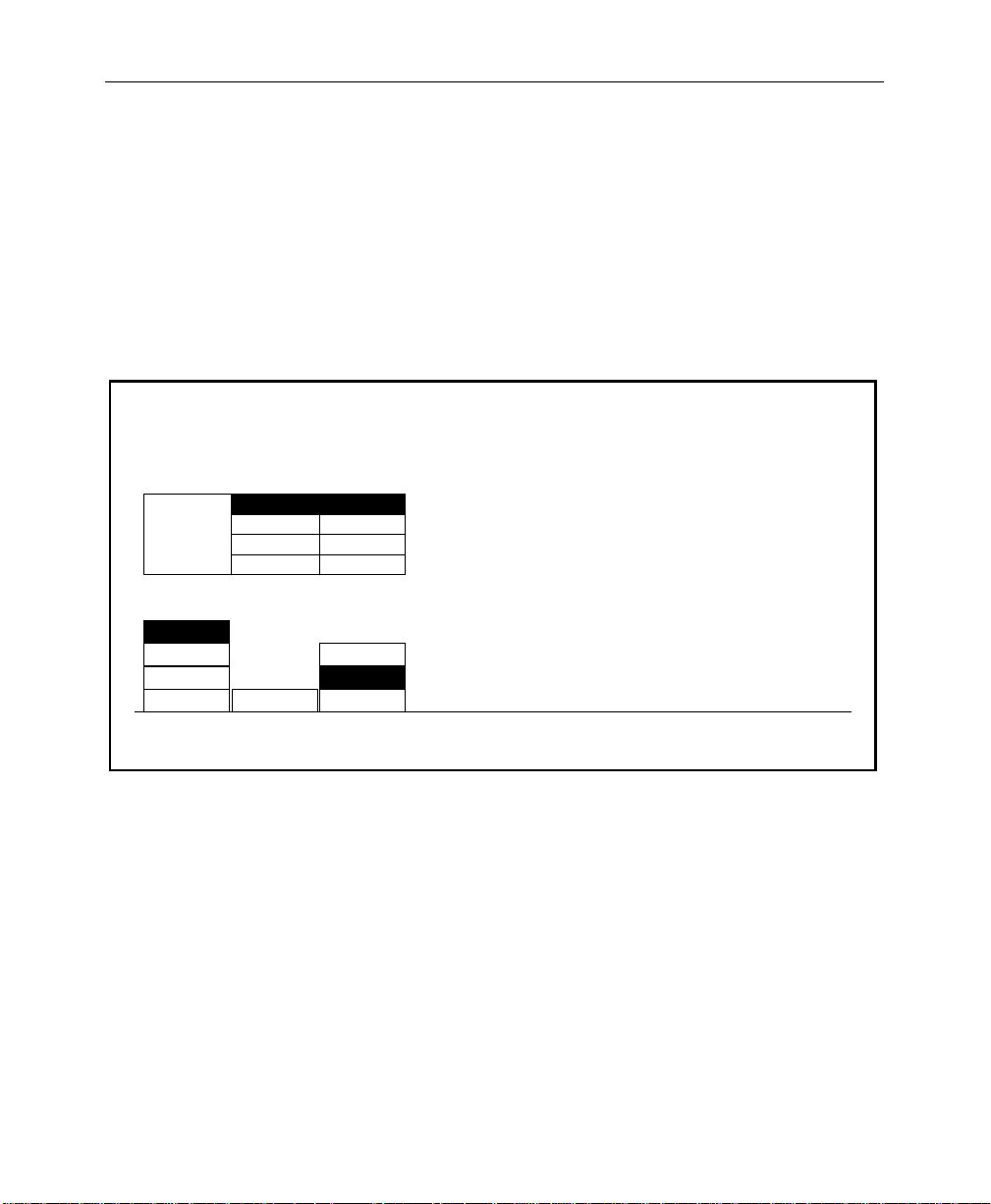
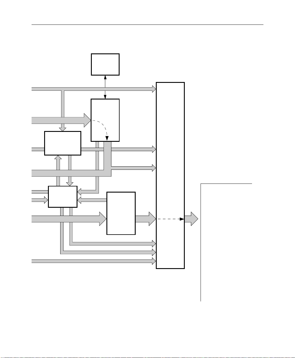
Physical Description
The switcher consists of three main areas: the Control Panel, the
Signal Processor Frame, and the Frame Power Supply (see
Figure 1-1). The electronic circuitry in the Model 3000 is primarily
contained on circuit boards and modules in the Signal Processor
Frame and Control Panel.
Signal Processor Frame
The Signal Processor Frame is a large rack-mounted unit that
houses the system controller, effects logic, video and key
processors, and input/output interfaces.
In addition to the basic system, a typical system may have several
options such as Chroma Keyers, Secondary Wipe Generator, and
Frame Store. Most options are available as circuit board modules
to be installed in the Signal Processor Frame.
Refer to the Model 3000 Installation and Service manual for a
complete description of the Signal Processor.
1-4
A main processor (HOS, or Head-Of-State) and separate
M/E processors reside within the Signal Processor Frame. Since
each M/E has its own processor, failure of one processor may not
disable the entire switcher. Individual effects can continue to
operate independently in a limited capacity.
Page 19
Power Supplies
Physical Description
Two power supplies are used in the basic Model 3000 system: a
control panel power supply, located in the control panel tub, and
a 19" rack mount power supply used by the Signal Processor
Frame. Optional Redundant power supplies are available.
TP0348-01
Pointing
Device
(bitpad)
CONTROL
PANEL
CONTROL PANEL
POWER SUPPLY
Control Panel
Figure 1-1. Simplified Block Diagram of the Model 3000 Switcher
Video/Key
Signals In
Frame
Panel
Link
INPUTS
AND
CROSS-
POINTS
CONTROLLER/
HEAD-OF-STATE
PROCESSOR
EFFECTS
PROCESSORS
EFFECTS
LOGIC
to
OUTPUT
AND
EXPAN-
SION
Signal
Video/Key
Signals Out
Processor
Frame
Frame
Power Supply
1-5
Page 20
Section 1 — System Overview
TP0348 01
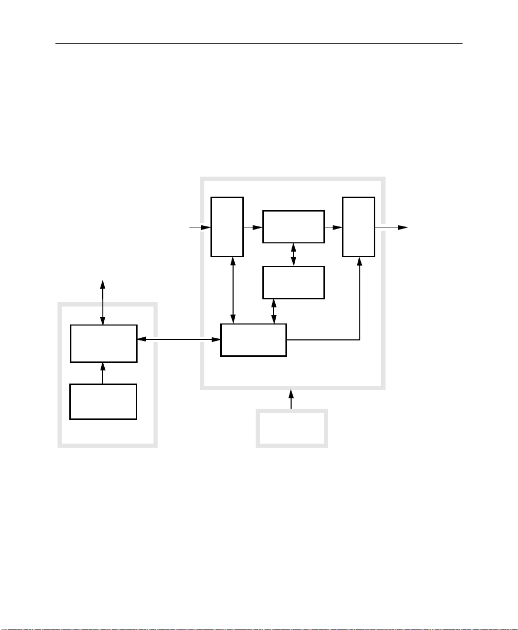
Control Panel
The Control Panel is the operator interface for the Model 3000
system. The operator performs all actions via physical buttons
and knobs and a software-driven menu.
Pointing
Device
(bitpad)
CONTROL
PANEL
CONTROL PANEL
POWER SUPPLY
Control Panel
Video/Key
Signals In
Frame
Panel
Link
INPUTS
AND
CROSSPOINTS
CONTROLLER/
HEAD-OF-STATE
PROCESSOR
EFFECTS
PROCESSORS
EFFECTS
LOGIC
to
OUTPUT
AND
EXPAN-
SION
Signal
Processor
Frame
Frame
Power Supply
Figure 1-2. Functional Areas of Model 3000-2 Control Panel
Video/Ke
Signals O
1-6
Page 21
Physical Description
The Control Panel also provides connectors for the Mask Draw
option and the data link to the Signal Processor Frame.
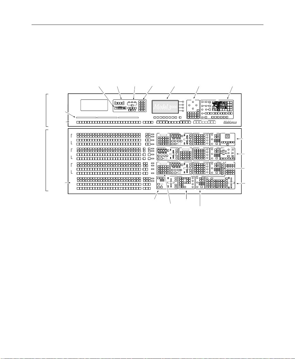
Upper
Panel
Lower
Panel
16.
Crosspoint
Name
Display
(Option)
17.
Preview/
Mask/Aux
Bus
1.
Source
Selection
M/E
CONFG
STAT
MODE
OPACITY
CHR
KEYER
WIPE
KEY
KEY
AUX
E-MEM
FRAME
BUS
FRAME
FIELD
FIELD
MATTE
MASK
STORE
2
1
LAST
MASK
DISK
MISC
MENU
STORE
M/E 1
COLOR
PGM
BKGD
CLR
SHIFT
2322212019181716
BKGD
CLR
2322212019181716 SHIFT
BKGD
COLOR
2322212019181716
SHIFT
BKGD
COLOR
2322212019181716
SHIFT
BKGD
M / E
CLR
2322212019181716BLK 15
SHIFT
1
BKGD
M / E
CLR
2322212019181716 SHIFT
1
BKGD
M / E
COLOR
2322212019181716
SHIFT
1
BKGD
M / E
COLOR
2322212019181716
SHIFT
1
BKGD
M / E
CLR
SHIFT
2322212019181716BLK 15
1
BKGD
M / E
CLR
2322212019181716 SHIFT
1
BKGD
M / E
COLOR
2322212019181716
SHIFT
1
BKGD
M / E
COLOR
2322212019181716
SHIFT
1
BKGD
CLR
M / E
SHIFT
23
22212019181716BLK 15
BKGD
1
CLR
M / E
22212019181716
23 SHIFT
BKGD
COLOR
M / E
22212019181716
SHIFT
BKGD
COLOR
M / E
22212019181716
2323SHIFT
BKGD
2. Transition
Subpanels
12B. Menu
Display
Buttons
M/E 2
M/E 3
PGM
PGM
PGM
M / E2M / E
UNCAL
3
M / E
M / E
UNCAL
2
3
M / E
M / E
UNCAL
3
2
M / E
M / E
UNCAL
2
3
M / E
UNCAL
3
M / E
UNCAL
3
M / E
UNCAL
3
M / E
UNCAL
3
M / E
UNCAL
2
M / E
UNCAL
2
M / E
UNCAL
2
M / E
UNCAL
2
M / E
M / E
UNCAL
2
3
M / E
M / E
UNCAL
2
1
3
M / E
M / E
2
1
3
M / E
M / E
2
1
3
12A. Menu
Display
F8 EXITF7F6F5F4F3F2F1
AUX 1-4 EFFECTS SEND ONLY
M/E 2
M/E 2
M/E 1AM/E 1BM/E 1
M/E 1
M/E 2
B
KEY 1
KEY 1
KEY 2
A
EFFECTS MEMORY
EFF EFF EFF EFF
88888888
BKGD
A
B
LOCK
9
RUN
708
ONON
LRN
LAYERED
BANK
SEQ
5
4
6
0
BANK
EFF
1
32
1
DIS
AUTO
UNDO
TRAN
CUT
ENTER
TRAN
RATE
BANK
•
TRANSITION
EFF EFF EFF EFF
KEY
KEY2KEY1BKGD
BKGD
PRIOR
A
B
ON
ONON
OVERONOVER
LAYERED
PST
EFFWIPEMIX
BLK
AUTO
CUT
TRAN
888
EFFECTS MEMORY
EFF EFF EFF EFF
88888888
BKGD
A
B
LOCK
9
RUN
708
ONON
LRN
LAYERED
BANK
SEQ
5
4
6
0
BANK
EFF
32
1
1
DIS
AUTO
UNDO
TRAN
CUT
ENTER
TRAN
RATE
BANK
•
TRANSITION
DSK
DSK
DSK 1
BKGD
2
1
CUT
ON
DSK 1
MIX
OVERONOVER
PST
BLK
060
DSK 2
CUT
DSK 2
AUTO
CUT
MIX
TRAN
3. M/E
Effects Memory
Subpanels
M/E 3
M/E 2
M/E 3
M/E 3
B
KEY 2
A
KEY 1
TRANSITION
KEY
KEY2KEY1BKGD
PRIOR
ON
OVERONOVER
PST
EFFWIPEMIX
BLK
888
EFFECTS MEMORY
KEY 1
88888888
CUT
LOCK
KEY 1
708
MIX
LRN
SEQ
5
4
KEY 2
EFF
CUT
1
DIS
KEY 2
UNDO
TRAN
MIX
RATE
BANK
•
TRANSITION
KEY
KEY2KEY1BKGD
PRIOR
ON
OVERONOVER
PST
EFFWIPEMIX
BLK
888
DOWNSTREAM KEYERS
EXTD
BORD
NORM
SHDW
KEY
INH
INV
OVER
MASK
MATTE
VIDEO
VIDEO
SPLIT
FILL
FILL
KEY
KEY
LUM
LIN
KEY
KEY
DSK
DSK
KEY
1
2
ON
4. Keyer
Subpanels
LEFT RIGHT
PRI
BOX
WIPE
M / E 2
M / E 1
KEY 1
KEY 1
M / E 2
M / E 1
KEY 2
KEY 2
M/E 3
KEY 2
KEY 1
CUT
KEY 1
MIX
KEY 2
CUT
KEY 2
MIX
9
RUN
BANK
6
0
BANK
32
1
ENTER
KEY 1
CUT
KEY 1
MIX
KEY 2
CUT
KEY 2
MIX
OUT
LINE
SHOW
KEY
AUTO
SEL
KEY
MASKS
TOP / GAIN
BOTTOM / CLIP
SEC
WIPE
M / E 3
KEY 1
M / E 3
KEY 2
BORDERLINE
SIZE / POS
BORDERLINE
OPACITY
GAIN
CLIP
PVW MASK
NORM
OVER
VIDEO
FILL
LIN
KEY
KEY
ON
NORM
KEY
OVER
VIDEO
FILL
LIN
KEY
KEY
ON
NORM
KEY
OVER
VIDEO
FILL
LIN
KEY
KEY
ON
5. Matte
Subpanels
11. Mask
Subpanel
SYMMETRY
SOFTNESS
OPACITY
WIDTH
MASK
INV
PRESET SIZE
ASPECT
ROTATION TYPE
MASK
MASK
BUS
STORE
ROT
ROT
POS
SPD
ROTATE
INH
DSK
MASK
1
DSK
FORCE
PATT
2
MASK
MIX
PATTERN MIX
BUS DELEGATE
AUX 2
AUX 3
AUX 4
AUX 1
A/B
A/B
A/B
KEYERS
OUT
BORD
SHDW
EXTD
LINE
BORDERLINE
SIZE / POS
INH
KEY
SHOW
FORCE
INV
MASK
KEY
MASK
BORDERLINE
AUTO
OPACITY
VIDEO
SPLIT
MATTE
SEL
KEY
KEY
FILL
KEY
PRI
SEC
CHR
LUM
GAIN
PST
PST
KEY
KEY
PTTN
PTTN
KEY
KEY
BKGD
BKGD
1
2
B
A
CLIP
KEYERS
OUT
BORD
SHDW
EXTD
LINE
BORDERLINE
SIZE / POS
INH
FORCE
SHOW
INV
MASK
MASK
KEY
BORDERLINE
AUTO
OPACITY
VIDEO
SPLIT
MATTE
SEL
KEY
KEY
FILL
KEY
PRI
SEC
CHR
LUM
GAIN
PST
PST
KEY
KEY
PTTN
PTTN
KEY
KEY
BKGD
BKGD
1
2
B
A
CLIP
KEYERS
OUT
BORD
SHDW
EXTD
LINE
BORDERLINE
SIZE / POS
INH
FORCE
SHOW
INV
MASK
KEY
MASK
BORDERLINE
AUTO
OPACITY
VIDEO
SPLIT
MATTE
SEL
KEY
KEY
FILL
KEY
PRI
SEC
CHR
LUM
GAIN
PST
PST
KEY
KEY
PTTN
PTTN
BKGD
BKGD
KEY
KEY
B
A
1
2
CLIP
MATTES
USER
SEC
AUTO
DEF
WIPE
RCL
WASH
WASH
HUE/
SOFTNESS
MATTE
FLAT
DPM
2
MATTE
1
DPM
K1 FILL K1 BORD
2
K2 FILL K2 BORD
SATURATION/
OFFSET
DPM
PRI WIPE SEC WIPE
3
MATTE
DPM
SEL
4
BRIGHT/TEX
SOFT
BORD
ASPCT
A/B
ENABL
ALL
MISC
BKGD
DSK
ROT
MAG
M / E 1
PRI
WIPE
AUX 5
A/B
HUE/
SOFTNESS
SATURATION/
OFFSET
BRIGHTNESS
HUE/
SOFTNESS
SATURATION/
OFFSET
BRIGHTNESS
HUE/
SOFTNESS
SATURATION/
OFFSET
BRIGHTNESS
GLOBL
INHIB
M/E
1
M/E
2
M/E
3
PGM
PST
WIPE
WIPE DIRECTION
FLIP
NORM REV
FLOP
DELEGATE
M / E 1
M / E 2
SEC
PRI
WIPE
WIPE
AUX 6
A/B
MATTES
PRI
SEC
WIPE
WIPE
WASH
WASH
MATTE
FLAT
2
MATTE
K1 FILL K1 BORD
K2 FILL K2 BORD
PRI WIPE SEC WIPE
MATTE
SEL
MATTES
PRI
SEC
WIPE
WIPE
WASH
WASH
MATTE
FLAT
2
MATTE
K1 FILL K1 BORD
K2 FILL K2 BORD
PRI WIPE SEC WIPE
MATTE
SEL
MATTES
PRI
SEC
WIPE
WIPE
WASH
WASH
MATTE
FLAT
2
MATTE
K1 FILL K1 BORD
K2 FILL K2 BORD
PRI WIPE SEC WIPE
MATTE
SEL
8888888888888888
LOCK
708
LRN
SEQ
4
EFF
1
DIS
UNDO
BANK
•
5
15.
Floppy
Disk Drive
Grass Valley Group
PVW/AUX
Grass Valley Group
BLK 15
KEY 1
KEY 2
M/E
A
1
B
KEY 1
KEY 2
M/E
A
2
B
KEY 1
KEY 2
M/E
A
3
B
DSK 1
DSK 2
PROGRAM
PRESET
14. External
Interface
Subpanel
EXTERNAL INTERFACE
141312111098765432BLACK 15 2322212019181716 SHIFT
141312111098765432
141312111098765432BLK 15
141312111098765432BLACK
15
141312111098765432BLACK
15
141312111098765432
141312111098765432BLK 15
141312111098765432BLACK
15
141312111098765432BLACK
15
141312111098765432
141312111098765432BLK 15
141312111098765432BLACK
15
141312111098765432BLACK
15
141312111098765432
141312111098765432BLK 15
141312111098765432BLACK
15
141312111098765432BLACK
15
13. Frame
Subpanel
AUXPERPHGPIEDIT
POSITIONVPOSITION
FRAME STORES
H
VIDEO
STORE
Store
DROP
SHDW
GRABFRZE
KEY
STORE
Figure 1-3. Functional Areas of Model 3000-3 Control Panel
10. Wipe
Subpanel
USER
USER
2
1
USER
USER
4
3
USER5USER
6
LEARN
USER
RANDOM
MENU
USER
TEXTURE
WIPE
WIPE
UNDO
POSITIONER
PATTERN MODIFIERS
H
POS
POS
SPLIT
MULTIVMULTI
NORM
AUTO
M/E 2
M / E 3
M/E 3
SEC
PRI
SEC
WIPE
WIPE
WIPE
POSITIONER
M/E 2
M/E 2
M/E 1
M/E 2
M/E 2
M/E 1
SEC
SEC
PRI
PRI
PRI
SEC
CTR
CHROMA KEYERS
R
LUM
SELECTIVITY
Y
M
G
B
C
SHADOW
CHROMA
OPACITY
SHDW
BKGD
ON
SUPR
M/E 3
M/E 3
M/E 1
M/E 1
M/E 2
M/E 2
KEY 1
KEY 2
KEY 1
KEY 2
KEY 1
KEY 2
EFFECTS MEMORY
PVW
PVW
CLEAR
CONST
PRI
GET
WORK
PUT
DUR
BUFR
M / E
GO
GO
1
TO
NEXT
PREV
TO
KF
TIME
M / E
EFF
KF
TIME
MARK
2
DUR
BLOCK
DUR
ALIGN
M / E
3
CUTMARK
COPY
PASTE
DSK
MOD
INSRT
INSRT
MOD
EVENT
BEFOR
AFTER
RE
WIND
FLIP
9
RUN
FLOP
BANK
6
REV
0
BANK
AUTO
32
1
RUN
STOP
TRAN
ENTER
NEXT
RATE
KF
9.
Positioner
Subpanel
8.
Chroma
Keyer
Subpanel
7.
Preview
Subpanel
6.
Master
Effects
Memory
Subpanel
TP0702-06B
1-7
Page 22

Section 1 — System Overview
Video and Key Inputs and Outputs
Inputs
Three types of input options may be installed in the Signal
Processor Frame to suit the needs of your installation. Each input
module supports four inputs and provides auto-timing of each
input.
The following types of input modules are available.
NOTE:
Each of these inputs can be treated by the switcher as either a
video input or a key input.
■
Analog 10-bit Composite Quad Input Module – Provides
noise filtering, anti-aliasing, and auto-timing of the input
signals, then performs an analog-to-digital conversion of each
signal and multiplexes the data onto a video or key bus.
Digital Bit-Parallel Quad Input Module – Converts the inputs
■
from ECL to TTL, auto-times the signals, and multiplexes
them onto the video or key bus.
Digital Bit-Serial Quad Input Module – Decodes the inputs
■
from serial to parallel, auto-times the signals, and multiplexes
the data onto the video or key bus.
In addition, RGB input modules are available with the Dual
Chroma Keyer option. Each module supports two sets of RGB
inputs (see Figure 1-4).
Refer to the Configuration section of the Getting Started manual
for information on assigning input formats and adjusting timing.
1-8
Page 23
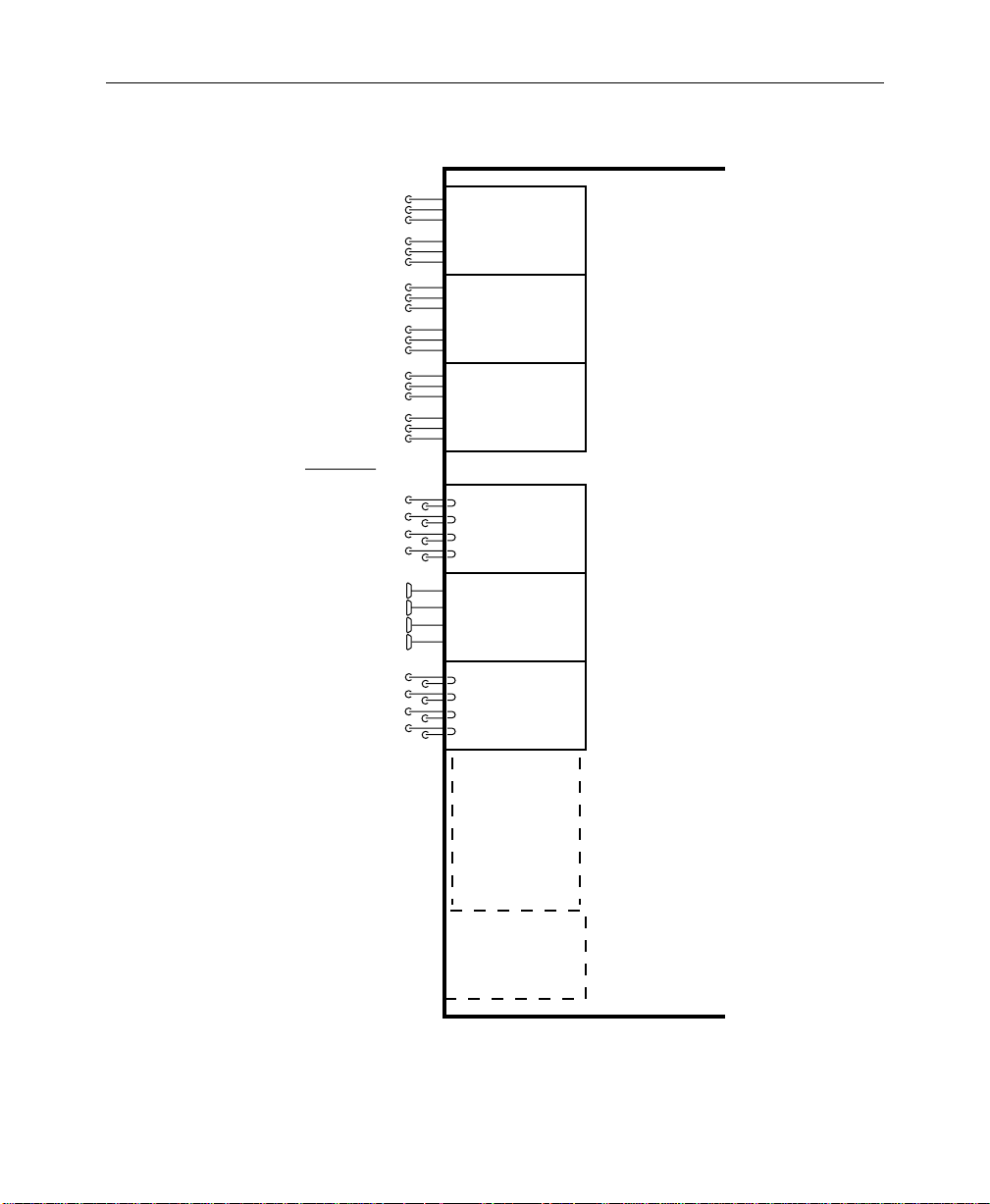
DUAL RGB
INPUT
MODULE
Video and Key Inputs and Outputs
DUAL RGB
INPUT
MODULE
Input Modules
Up to 3 Dual RGB
(Any mix of module types)
Up to 16 Quad Input Modules
DUAL RGB
INPUT
MODULE
QUAD
ANALOG INPUT
MODULE
QUAD
PARALLEL DIGITAL
INPUT MODULE
QUAD
SERIAL DIGITAL
INPUT MODULE
0702-03
Module Cells A1 through A3
Signal
Processor
Frame
Module Cells C1 through C16
Figure 1-4. Video and Key Inputs
1-9
Page 24

Section 1 — System Overview
Outputs
Regardless of the format of the input signals, the Signal Processor
can provide outputs in any composite format.
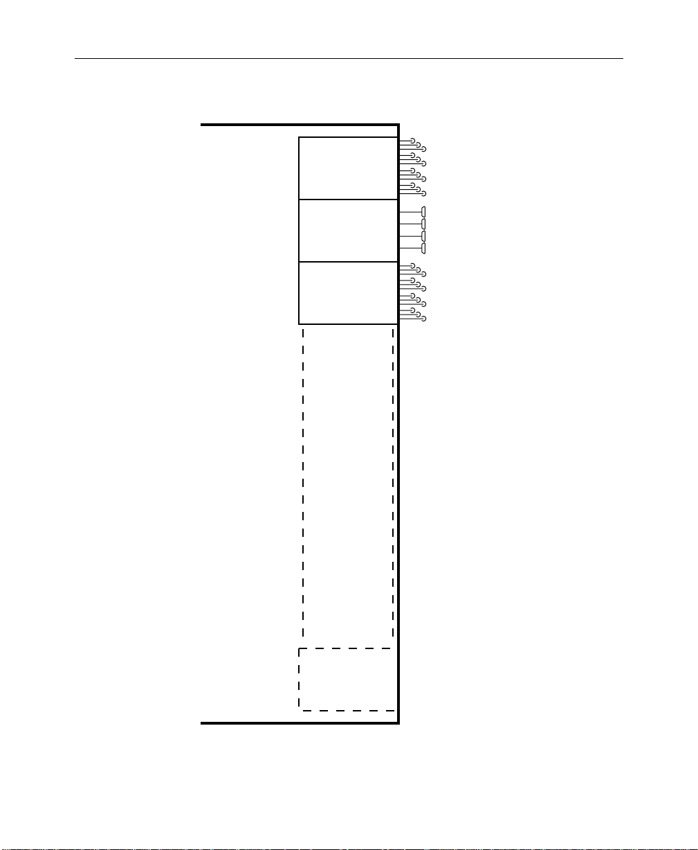
Signal outputs are provided by output modules installed in the
Signal Processor Frame (see Figure 1-5). Each output module
provides four video/key signal outputs of a given type, with up
to three buffered outputs per signal channel.
Since each output module
cell
is dedicated to specific functions,
the format of each output signal is determined by the type of
output module installed in that cell. The following choices of
output modules are available:
Composite Analog (4 signal channels; 3 outputs of each
■
signal)
■
Parallel Digital (4 signals; 1 output of each signal)
■
Serial Digital (4 signals; 3 outputs of each signal)
Standard (Analog) outputs include:
■
(DSK) Program Video
■
(DSK) Program Key
■
Mask Bus
■
Switched Preview Video
Optional outputs (Analog and/or Digital) include:
■
M/E 1 Program Video, M/E 1 Program Key
■
M/E 1 Preview Video
■
M/E 2 Program Video, M/E 2 Program Key
■
M/E 2 Preview Video
■
M/E 3 Program Video, M/E 3 Program Key (3000-3 only)
■
M/E 3 Preview Video (3000-3 only)
■
DSK Preview
■
DSK Preview Video
■
Aux Buses 1A-4B, Aux Buses 5A-7B
■
Clean Feed Video
■
Frame Store Video and Key
1-10
Page 25
Video and Key Inputs and Outputs
Signal
Processor
Frame
QUAD
ANALOG OUTPUT
MODULE
QUAD
PARALLEL DIGITAL
OUTPUT MODULE
QUAD
SERIAL DIGITAL
OUTPUT MODULE
Module Cells A4 through A17
4 Signal Channels
per Module
3 Outputs of
each Signal
4 Signal Channels
per Module
1 Output of
each Signal
4 Signal Channels
per Module
3 Outputs of
each Signal
(Any mix of module types)
Up to 14 Quad Output Modules
Figure 1-5. Video and Key Outputs
1-11
Page 26

Section 1 — System Overview
Functional Description
Overview
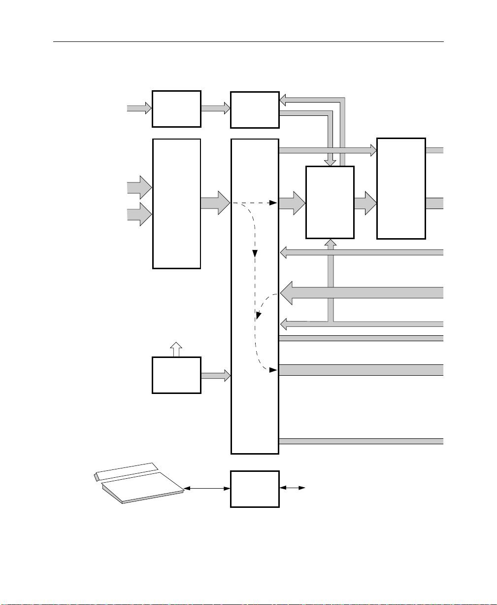
Figure 1-6 shows the video flow in a typical Model 3000 switching
system.
Video and key signals enter the Input Section of the Model 3000,
which consists of analog, parallel digital, and/or serial digital
modules. The analog signals are converted to digital format, and
all inputs are timed and conditioned.
The digital signals are then passed to the V ideo and Effects Section
where keying and mixing take place. This section also provides
effect modifications, such as wipes, that can be applied to selected
inputs.
In the Output Section, digital video and key signals are converted
to any desired composite format (analog, parallel digital, or serial
digital), as predetermined by the type of output modules
installed, before leaving the Signal Processor.
Video Processing
1-12
Input video and key signal selections are made by the Crosspoint
Matrix under control of the system Controller, according to
operator assignments entered via the Control Panel.
In addition to primary (external) video, secondary (internal)
sources such as Masks, M/E re-entry video, and optional Frame
Store are available as inputs to the crosspoint matrix.
Two sets of RGB signals may be applied per optional Dual RGB
input module. These inputs are forwarded to a Dual Chroma
Keyer module.
Keyers in each Mix/Effects bank provide outputs to the Effects
Loop crosspoints for sending outside the switcher for external
processing or for routing to the M/E mixers and wipe generators.
Page 27

Functional Description
The Effects Send outputs can also be directed to the Frame Store
option for image capture. One optional Effects Loop Crosspoint
module services all three Mix/Effects banks.
Each M/E has two keyers and two background buses (A and B) as
inputs. In standard mode, Keyers 1 and 2 can be mixed into a
composite video and key which can be forwarded to the DSK, the
other M/E, or output. In layered mode, Backgrounds A and B are
also used as keyers that operate in a manner similar to Keyers 1
and 2.
Optional preview capability allows monitoring of sources at
certain points in the signal flow. You can preview video from the
M/E mixers, Flip/Flop Mix and DSK mixer, switched preview
bus, or mask bus.
Eight pulse- or level-sensitive GPI inputs are provided. You can
assign each of these inputs via the GPI Input menu to perform a
specific function when triggered.
The editor interface consists of an asynchronous RS-422, 38.4K
baud serial communications port, managed by a communications
processor .
1-13
Page 28
Section 1 — System Overview
RGB
Inputs
Video Signals
In
Key Signals
In
0702-05L
DUAL
RGB INPUT
MODULES
QUAD
INPUT
MODULES
ANALOG,
PARALLEL
DIGITAL,
AND
SERIAL
DIGITAL
Clocks
SYNC
GENERATOR
Black,
Back-
ground,
and
Test
Signals
DUAL
CHROMA
KEYERS
80 X 48
VIDEO
CROSSPOINT
MATRIX
M/E1,
M/E2 & M/E3
Chr. Key
M/E
Video
and
Key
MODULES –
QUAD
KEYER
M/E 1,
M/E 2,
& M/E 3
Aux Bus
1A-4B
EFFECTS
LOOP
CROSS-
POINTS
Frame Store Video and Key
M/E Program Video and Key
Clipped Mask and
Mask Store Video
Switched Preview and Mask
Program, Preset, and DSK Video and Key
Aux Bus 5A-7B Video and Key
1-14
CONTROL PANEL
CONTROLLER
(control buses not
shown for simplicity)
To/From
All Circuits
Page 29
Aux Bus 1A-4B
Video and Key
SECONDARY
WIPE
OPTION
M/E 1, M/E 2
& M/E 3
MIXERS
Functional Description
0702-05R
FRAME STORE
FOR VIDEO, KEY,
AND MASK
STORAGE
Mask
Store
Input
PREVIEW
Mask
Store
Output
M/E Pvw
Video
DSK Pvw
Video
Mask and
Switched Preview
M/E and DSK Preview
Frame Store
Video
and Key
M/E 1, M/E 2,
& M/E 3
Program Video
and Key
Program
PGM/PST
MIXER
AND
DUAL DSK
Video
& Key
& Clean
Feed
Video
NOTE:
Primary Video Paths are
Indicated by Wide Arrows
QUAD
OUTPUT
MODULES
ANALOG,
PARALLEL
DIGITAL,
AND
SERIAL
DIGITAL
Outputs
Frame Store Video and Key
M/E 1, M/E 2, & M/E 3
Program Video and Key
Program Video and Key
Clean Feed Video
DSK Preview Video
Mask
Switched Preview
M/E1, M/E 2, & M/E 3
Preview
DSK Preview
Aux Bus Video and Key
Figure 1-6. Video Flow Diagram of Typical Model 3000 Switching System
1-15
Page 30

Section 1 — System Overview
Description of Options
The following options are currently available for the Model 3000
Switcher. For more details on these options, refer to the
appropriate subpanel descriptions later in this manual.
Dual Chroma Keyer
Up to six analog component (RGB, YUV, or Betacam®) or
composite inputs can be chroma keyed, two per Dual Chroma
Keyer module. Each module is added to a specific M/E.
Borderline Key Edge Generation
Borderline® Key Edge Generators are available for each keyer in
the switcher. The Borderline feature is implemented as a
mezzanine board that plugs onto the Keyer module of any M/E.
Each Borderline generator supports 1, 2, or 3 line wide borders for
border and outline modes and 1 to 6 line wide edges for shadow
and extrude modes. Fill within the key edges may be either video
or matte.
Secondary Wipe Generator
A Secondary Wipe Generator module provides a second pattern
for each of the M/E systems. Only one module is required for
enhancing all mix/effect systems.
1-16
Page 31

Safe Title/Action Area Generator
The Safe Title/Action Area Generator provides up to four
different patterns that can be superimposed on the switched
preview output of the switcher . It may be used to define a safe title
area, safe action area, or for screen centering and horizontal/
vertical alignment of picture elements.
Mix/Effects Clean Feed
A clean feed output of the wipe/mix signals (the two backgr ound
bus video signals without any keys added) is provided by a LookAhead Preview mezzanine board installed on the Mixer and
Primary Wipe Generator module.
Frame Store
The Frame Store option allows storage and retrieval of images at
a resolution of 10 bits. Either two two-field pictures and keys or
one four-field picture and key can be frozen in the Frame Stor e. A
two-field mask store is also provided.
Description of Options
Effects Send
Effects Send provides a method of integrating digital effects
devices into the switcher mix/effects system. Up to four send
channels can be used to route the video and key from an M/E to
and from an external digital effects system.
1-17
Page 32

Section 1 — System Overview
Tally Output
The Tally Relay module provides tally outputs that reflect the
switcher status. A rear-panel interconnect board provides the
relay contacts at two connectors for on-air T ally A and on-air Tally
B. Pinouts for the Tally connectors are given in the Installation
section of the System Information manual.
Tally Expansion
The T ally Expansion Option increases the number of tally outputs
from the Model 3000 Switcher. An unlimited number of Tally
Expansion frames, each with up to three tally modules, can be
added to the switcher.
Remote Auxiliary Bus Control Panels
Three models of Remote Aux Control Panels are available for
controlling your switcher auxiliary buses from a remote location.
The one- and two-RU panels each control a single aux bus; the
three-RU panel provides delegated control of any number of aux
buses.
Chroma Key Auto Setup
The Chroma Key Auto Setup option is a software option that
automatically sets up a chroma key when you identify the
background color. This option requires the presence of the Frame
Store option.
1-18
Page 33

2
Control Panel Descriptions
Introduction
User control of the Model 3000 Switcher is provided through a
control panel containing a source-select button matrix, various
“subpanels” and a flat panel text and graphics display called the
“menu display.”
This section provides an overview of the Model 3000-2 and
Model 3000-3 control panels, and detailed descriptions of the
subpanels. Operation of the 3000-2 and the 3000-3 is essentially
identical; however, the 3000-3 has one more M/E, additional
crosspoint buttons on the panel, discrete (rather than delegated)
key buses, an E-MEM panel for each M/E, and keyer mix and cut
buttons.
Main Control Panel
The control panel is physically divided into two areas referred to
as the “upper” and “lower” panels (see Figure 2-1 and 2-2).
The upper panel contains the main menu subpanel and the menu
display, as well as the Wipes, Masks, Frame Stores, and External
Interface subpanels and a 3.5-inch floppy disk drive used for
storing setups and other data.
Menu control for selecting and executing software functions is
provided by the main menu buttons at the left of the display, plus
eight “soft” buttons below the display and four “soft” knobs to the
right of the display. The term “soft” means that the functions of
these buttons and knobs are defined by software.
2-1
Page 34

Section 2 — Control Panel Descriptions
Functions available through the Menus are described in the next
section of this manual
Frequently-used controls are located on the lower panel for ease
of reach by the operator. Rows of subpanels for the Mix/Effects
and Program/Preset/Downstream Keyer systems ar e provided in
line with the corresponding source selection buttons for making
transitions, keying, creating mattes, and manipulating effects.
Buttons for the Preview bus, Effects Send, Mask bus, and
Auxiliary bus selections are located along the top of the lower
panel for the Model 3000-2, or along the bottom of the upper panel
for the 3000-3.
The subpanel descriptions in this section are arranged in the
following sequence, starting at the lower left and moving
counterclockwise around the panel:
2-2
Store
FIELD
FIELD
2
1
MASK
STORE
12B. Menu
Display
Buttons
M/E
CONFG
STAT
MODE
CHR
KEYER
WIPE
KEY
OPACITY
KEY
AUX
E-MEM
FRAME
BUS
FRAME
MASK
MATTE
STORE
LAST
DISK
MISC
MENU
M/E 1
M/E 2
BKGD
BKGD
SHIFT
141312111098765432BLACK
PGM
PGM
1
2
KEY 1
BKGD
BKGD
M / E
141312111098765432BLACK
SHIFT
1
2
KEY 2
BKGD
BKGD
M / E
141312111098765432BLACK
SHIFT
1
2
BKGD
BKGD
M / E
141312111098765432BLACK
SHIFT
1
2
KEY 1 UNCAL
BKGD
BKGD
M / E
141312111098765432BLACK
SHIFT
1
2
1
KEY 2 UNCAL
BKGD
BKGD
M / E
141312111098765432BLACK
SHIFT
1
2
1
BKGD
BKGD
M / E
141312111098765432BLACK
SHIFT
1
2
1
M / E2M / E
BKGD
BKGD
141312111098765432BLACK
SHIFT
1
1
2
M / E2M / E
BKGD
BKGD
141312111098765432BLACK
SHIFT
1
1
2
M / E2M / E
BKGD
BKGD
141312111098765432BLACK
SHIFT
1
2
1
2
2
2
PGM
UNCAL
UNCAL
UNCAL
UNCAL
UNCAL
UNCAL
UNCAL
UNCAL
UNCAL
AUX 1-4 EFFECTS SEND ONLY
M/E 1BM/E 1AM/E 1
KEY 1
TRANSITION
EFF
EFF
EFF
EFF
SEND
SEND
SEND
SEND
KEY2KEY1BKGD
BKGD
A
B
ON
ONON
OVERONOVER
LAYERED
PST
WIPEMIX
BLK
AUTO
CUT
TRAN
060
TRANSITION
TRANSITION
DSK2DSK
BKGD
1
ON
OVERONOVER
PST
BLK
AUTO
CUT
TRAN
060
Subpanels
12A. Menu
Display
M/E 2
M/E 1
M/E 2
M/E 2
A
KEY 2
B
KEY 1
KEY
PRIOR
EFF
EFF
EFF
EFF
SEND
SEND
SEND
SEND
BKGD
KEY
KEY2KEY1BKGD
B
PRIOR
A
ON
ONON
OVERONOVER
LAYERED
PST
WIPEMIX
BLK
AUTO
CUT
TRAN
060
EXIT
M/E 2
KEY 2
Subpanels
M / E 1
KEY 1
M / E 1
KEY 2
PREVIEW ONLY
M/E 2
M/E 1
PVW
PVW
KEYERS
BORD
NORM
SHDW
KEY
FORCE
INH
OVER
MASK
MASK
SPLIT
MATTE
VIDEO
KEY
FILL
FILL
LUM
LIN
CHR
KEY
KEY
KEY
KEY
BKGD
ON
A
B
KEYERS
BORD
NORM
SHDW
KEY
FORCE
INH
OVER
MASK
MASK
VIDEO
MATTE
SPLIT
FILL
FILL
KEY
LUM
LIN
CHR
KEY
KEY
KEY
KEYONKEY
BKGD
BKGD
A
B
DOWNSTREAM KEYERS
BORD
NORM
SHDW
KEY
INH
OVER
MASK
MATTE
VIDEO
SPLIT
FILL
FILL
KEY
LUM
LIN
KEY
KEY
DSK
DSK
KEY
2
1
ON
4. Keyer
LEFT RIGHT
PRI
BOX
WIPE
M / E 2
KEY 1
M / E 2
KEY 2
DSK
PVW
OUT
EXTD
LINE
SHOW
INV
KEY
AUTO
VIDEO
SEL
KEY
KEY
SEC
PRI
PST
PST
PTTN
PTTN
KEY
KEY1BKGD
2
OUT
EXTD
LINE
SHOW
INV
KEY
AUTO
VIDEO
SEL
KEY
KEY
PRI
SEC
PST
PST
PTTN
PTTN
KEY
2
1
OUT
EXTD
LINE
SHOW
INV
KEY
AUTO
VIDEO
SEL
KEY
KEY
11. Mask
Subpanel
MASKS
TOP / GAIN
BOTTOM / CLIP
MASK
SEC
BUS
WIPE
DSK
1
FORCE
MASK
DSK
2
SIZE / POS
OPACITY
GAIN
CLIP
SIZE / POS
OPACITY
GAIN
CLIP
SIZE / POS
OPACITY
GAIN
CLIP
SYMMETRY
SOFTNESS
OPACITY
WIDTH
MASK
INV
PRESET SIZE
ASPECT
ROTATION TYPE
MASK
STORE
ROT
POS
ROTATE
INH
MASK
PATT
MIX
PATTERN MIX
BUS DELEGATE
AUX1AUX2AUX3AUX
PVW MASK
MATTES
PRI
SEC
WIPE
WIPE
WASH
WASH
HUE/
SOFTNESS
FLAT
MATTE
MATTE
2
K1 FILL K1 BORD
K2 FILL K2 BORD
SATURATION/
OFFSET
PRI WIPE SEC WIPE
MATTE
SEL
BRIGHTNESS
MATTES
PRI
SEC
WIPE
WIPE
WASH
WASH
HUE/
SOFTNESS
FLAT
MATTE
MATTE
2
K1 FILL K1 BORD
K2 FILL K2 BORD
SATURATION/
OFFSET
PRI WIPE SEC WIPE
MATTE
SEL
BRIGHTNESS
MATTES
USER
SEC
DEF
WIPE
WASH
WASH
HUE/
SOFTNESS
FLAT
MATTE
MATTE
2
K1 FILL K1 BORD
K2 FILL K2 BORD
SATURATION/
OFFSET
BKGD 1 BKGD 2
MATTE
SEL
BRIGHT / TEX
5. Matte
Subpanels
SOFT
BORD
ASPCT
WIPE DIRECTION
ROT
ROT
NORM REV
SPD
MAG
DELEGATE
M / E 1
M / E 1
PRI
SEC
WIPE
WIPE
AUX 5 AUX
4
CHROMA KEYERS
R
SELECTIVITY
Y
M
B
G
C
SHADOW
OPACITY
HUE
SHDW
ON
M/E 1
M/E 1
M/E 2
KEY 1
KEY 2
KEY 1
CLR
CONST
WORK
GET
DUR
BUFR
GO
PREV
NEXT
TO
TIME
EFF
TIME
MARK
DUR
ALIGN
BLOCK
CUTMARK
COPY
PASTE
INSRT
MOD
MOD
BEFOR
AFTER
EVENT
GLOBL
AUTO
ENABLES
INHIB
RCL
DPM
ENABL
M/E
1
ALL
1
DPM
M/E
MISC
2
2
DPM
BKGD
3
PGM
DPM
DSK
PST
4
Upper
Panel
Lower
Panel
15.
Floppy
Disk
Drive
17.
Preview/
Mask/Aux
Bus
14. External
Interface
Subpanel
Grass Valley Group
EXTERNAL INTERFACE
PVW
AUX
KEY
A
13. Frame
Subpanel
®
FRAME STORES
DROP
AUXPERPHGPIEDIT
SHDW
H
POSITIONVPOSITION
GRABFRZE
KEY
VIDEO
STORE
STORE
B
KEY
A
B
DSK
PGM
PST
1. Source Selection 2. Transition
Figure 2-1. Functional Areas of Upper and Lower Control Panels (3000-2)
10. Wipe
Subpanel
WIPE
FLIP
FLOP
M / E 2
M/E 2
PRI
SEC
WIPE
WIPE
6
LUM
CHROMA
BKGD
SUPR
M/E 2
KEY 2
EFFECTS MEMORY
RE
PUT
WIND
GO
FLIP
TO
FLOP
KF
KF
REV
DUR
AUTO
RUN
STOP
INSRT
NEXT
KF
8888888888888888
LOCK
LRN
SEQ
EFF
DIS
BANK
USER
TP0348-06B
USER
2
1
USER
USER
4
3
USER5USER
6
LEARN
USER
RANDOM
MENU
USER
TEXTURE
WIPE
WIPE
UNDO
PATTERN MODIFIERS
POSITIONER
H
POS
POS
SPLIT
MULTIVMULTI
NORM
AUTO
POSITIONER
M/E 1
M/E 1
PRI
SEC
WIPE
WIPE
CTR
M/E 2
M/E 2
PRI
SEC
WIPE
WIPE
7
8
9
RUN
BANK
4
5
6
1
BANK
1
2
3
2
UNDO
TRAN
ENTER
0
RATE
•
8.
Chroma
Keyer
Subpanel
9.
Positioner
Subpanel
6.
Effects
Memory
(E-MEM®)
Subpanel
Page 35

Main Control Panel
1. Source Selection 10. Wipe Subpanel
2. Transition Subpanels 11. Mask Subpanel
3. M/E E-MEM Subpanels (3000-3 only) 12. Menu Display Subpanel
4. Keyer Subpanels 13. Frame Store Subpanel
5. Matte Subpanels 14. External Interface Subpanel
6. Master Effects Memory Subpanel 15. floppy Disk Drive
7. Preview Subpanel (3000-3 only) 16. Crosspoint Name Display (3000-3 Option)
8. Chroma Keyer Subpanel 17. Preview/Mask/Aux Bus
9. Positioner Subpanel 18. Preview/Mask/Aux Bus
Upper
Panel
Lower
Panel
16.
Crosspoint
Name
Display
(Option)
17.
Preview/
Mask/Aux
Bus
1.
Source
Selection
15.
Floppy
Disk Drive
Grass Valley Group
PVW/AUX
Grass Valley Group
BLK 15
KEY 1
KEY 2
M/E
A
1
B
KEY 1
KEY 2
M/E
A
2
B
KEY 1
KEY 2
M/E
A
3
B
DSK 1
DSK 2
PROGRAM
PRESET
14. External
Interface
Subpanel
13. Frame
Store
Subpanel
FRAME STORES
EXTERNAL INTERFACE
AUXPERPHGPIEDIT
H
OPACITY
POSITIONVPOSITION
DROP
SHDW
FIELD
FIELD
GRABFRZE
2
1
KEY
VIDEO
MASK
STORE
STORE
STORE
141312111098765432BLACK 15 2322212019181716 SHIFT
141312111098765432
141312111098765432BLK 15
141312111098765432BLACK
15
141312111098765432BLACK
15
141312111098765432
141312111098765432BLK 15
141312111098765432BLACK
15
141312111098765432BLACK
15
141312111098765432
141312111098765432BLK 15
141312111098765432BLACK
15
141312111098765432BLACK
15
141312111098765432
141312111098765432BLK 15
141312111098765432BLACK
15
141312111098765432BLACK
15
2322212019181716
2322212019181716 SHIFT
2322212019181716
2322212019181716
2322212019181716BLK 15
2322212019181716 SHIFT
2322212019181716
2322212019181716
2322212019181716BLK 15
2322212019181716 SHIFT
2322212019181716
2322212019181716
22212019181716BLK 15
23
22212019181716
23 SHIFT
22212019181716
22212019181716
2323SHIFT
12B. Menu
Display
Buttons
M/E
CONFG
STAT
MODE
CHR
KEYER
WIPE
KEY
KEY
AUX
E-MEM
FRAME
BUS
FRAME
MATTE
MASK
STORE
LAST
DISK
MISC
MENU
M/E 2
M/E 1
M/E 3
COLOR
PGM
PGM
PGM
PGM
BKGD
M / E2M / E
CLR
SHIFT
UNCAL
3
BKGD
M / E
M / E
CLR
UNCAL
3
2
BKGD
M / E
M / E
COLOR
SHIFT
UNCAL
2
3
BKGD
M / E
M / E
COLOR
SHIFT
UNCAL
2
3
BKGD
M / E
M / E
CLR
UNCAL
SHIFT
3
1
BKGD
M / E
M / E
CLR
UNCAL
3
1
BKGD
M / E
M / E
COLOR
UNCAL
SHIFT
3
1
BKGD
M / E
M / E
COLOR
UNCAL
SHIFT
3
1
BKGD
M / E
M / E
CLR
UNCAL
SHIFT
2
1
BKGD
M / E
M / E
CLR
UNCAL
2
1
BKGD
M / E
M / E
COLOR
UNCAL
SHIFT
1
2
BKGD
M / E
M / E
COLOR
UNCAL
SHIFT
1
2
BKGD
M / E
M / E
M / E
CLR
SHIFT
UNCAL
3
2
1
BKGD
M / E
M / E
M / E
CLR
UNCAL
3
1
2
BKGD
M / E
M / E
COLOR
M / E
SHIFT
3
1
BKGD
2
M / E
M / E
COLOR
M / E
1
3
BKGD
2
2. Transition
Subpanels
12A. Menu
Display
F8 EXITF7F6F5F4F3F2F1
AUX 1-4 EFFECTS SEND ONLY
M/E 2
M/E 2
EFFECTS MEMORY
88888888
708
4
1
UNDO
•
A
ONON
AUTO
TRAN
EFFECTS MEMORY
88888888
708
4
1
UNDO
•
DSK
1
060
AUTO
TRAN
M/E 2
M/E 1
M/E 2
B
KEY 1
KEY 2
KEY 1
KEY 2
A
EFF EFF EFF EFF
BKGD
A
B
9
RUN
ONON
LAYERED
BANK
5
6
0
BANK
32
1
AUTO
TRAN
CUT
ENTER
TRAN
RATE
TRANSITION
KEY 1
CUT
KEY
KEY2KEY1BKGD
PRIOR
KEY 1
ON
MIX
OVERONOVER
PST
KEY 2
EFFWIPEMIX
BLK
CUT
KEY 2
MIX
888
EFF EFF EFF EFF
BKGD
A
B
9
RUN
ONON
LAYERED
BANK
5
6
0
EFFWIPEMIX
BANK
32
1
AUTO
TRAN
CUT
ENTER
TRAN
RATE
TRANSITION
DSK
DSK 1
2
CUT
ON
DSK 1
MIX
OVERONOVER
DSK 2
CUT
DSK 2
MIX
M/E 1AM/E 1BM/E 1
LOCK
LRN
SEQ
EFF
DIS
BANK
EFF EFF EFF EFF
BKGD
B
LAYERED
CUT
LOCK
LRN
SEQ
EFF
DIS
BANK
BKGD
PST
BLK
CUT
4. Keyer
3. M/E
Effects Memory
Subpanels
LEFT RIGHT
BOX
M / E 2
M / E 1
KEY 1
M / E 2
M / E 1
KEY 2
M/E 3
M/E 3
M/E 3
M/E 3
B
A
KEY 1
KEY 2
TRANSITION
KEY 1
KEY
KEY2KEY1BKGD
PRIOR
KEY 1
ON
OVERONOVER
PST
KEY 2
EFFWIPEMIX
BLK
KEY 2
888
EFFECTS MEMORY
88888888
LOCK
9
RUN
708
LRN
BANK
SEQ
5
4
6
BANK
EFF
32
1
DIS
UNDO
TRAN
ENTER
RATE
BANK
•
TRANSITION
KEY 1
KEY
KEY2KEY1BKGD
PRIOR
KEY 1
ON
OVERONOVER
PST
KEY 2
BLK
KEY 2
888
DOWNSTREAM KEYERS
OUT
EXTD
BORD
NORM
SHDW
LINE
SHOW
KEY
INH
INV
KEY
OVER
MASK
AUTO
VIDEO
MATTE
VIDEO
SPLIT
SEL
FILL
FILL
KEY
KEY
KEY
LIN
LUM
KEY
KEY
KEY
DSK
DSK
ON
1
2
Subpanels
11. Mask
Subpanel
MASKS
TOP / GAIN
BOTTOM / CLIP
MASK
INV
MASK
SEC
PRI
MASK
BUS
WIPE
WIPE
STORE
INH
M / E 3
DSK
KEY 1
MASK
KEY 1
1
M / E 3
DSK
FORCE
KEY 2
2
KEY 2
MASK
AUX 1
PVW MASK
A/B
KEYERS
BORD
NORM
SHDW
CUT
INH
KEY
FORCE
MASK
OVER
MASK
MIX
SPLIT
MATTE
VIDEO
KEY
FILL
FILL
CHR
LUM
LIN
CUT
KEY
KEY
KEY
KEY
BKGD
BKGD
MIX
ON
B
A
KEYERS
BORD
NORM
SHDW
INH
KEY
FORCE
MASK
OVER
MASK
SPLIT
MATTE
VIDEO
KEY
FILL
FILL
0
CHR
LUM
LIN
KEY
KEY
KEY
1
KEY
BKGD
BKGD
ON
B
A
KEYERS
BORD
NORM
SHDW
CUT
INH
KEY
FORCE
MASK
OVER
MASK
MIX
SPLIT
MATTE
VIDEO
KEY
FILL
FILL
CHR
LUM
LIN
CUT
KEY
KEY
KEY
KEY
BKGD
BKGD
MIX
ON
B
A
MATTES
USER
DEF
WASH
BORDERLINE
HUE/
SIZE / POS
SOFTNESS
FLAT
MATTE
BORDERLINE
K1 FILL K1 BORD
OPACITY
K2 FILL K2 BORD
SATURATION/
OFFSET
PRI WIPE SEC WIPE
GAIN
CLIP
BRIGHT/TEX
5. Matte
Subpanels
10. Wipe
Subpanel
WIPE
SOFT
SYMMETRY
SOFTNESS
BORD
OPACITY
WIDTH
ASPCT
PRESET SIZE
ASPECT
ROTATION TYPE
ROT
ROT
ROT
NORM REV
POS
SPD
MAG
ROTATE
M / E 1
PATT
PRI
MIX
WIPE
PATTERN MIX
BUS DELEGATE
AUX 2
AUX 3
AUX 4
AUX 5
A/B
A/B
A/B
A/B
OUT
EXTD
LINE
BORDERLINE
HUE/
SIZE / POS
SOFTNESS
SHOW
INV
KEY
BORDERLINE
AUTO
OPACITY
VIDEO
SEL
KEY
KEY
SATURATION/
PRI
SEC
OFFSET
GAIN
PST
PST
PTTN
PTTN
KEY
KEY
1
2
CLIP
BRIGHTNESS
OUT
EXTD
LINE
BORDERLINE
HUE/
SIZE / POS
SOFTNESS
SHOW
INV
KEY
BORDERLINE
AUTO
OPACITY
VIDEO
SEL
KEY
KEY
SATURATION/
OFFSET
PRI
SEC
GAIN
PST
PST
PTTN
PTTN
KEY
KEY
1
2
CLIP
BRIGHTNESS
OUT
EXTD
LINE
BORDERLINE
HUE/
SIZE / POS
SOFTNESS
SHOW
INV
KEY
BORDERLINE
AUTO
OPACITY
VIDEO
SEL
KEY
KEY
SATURATION/
OFFSET
PRI
SEC
GAIN
PST
PST
PTTN
PTTN
KEY
KEY
1
2
CLIP
BRIGHTNESS
SEC
AUTO
GLOBL
WIPE
RCL
INHIB
WASH
MATTE
DPM
ENABL
M/E
2
1
ALL
1
DPM
M/E
MISC
2
2
M/E
DPM
BKGD
3
3
MATTE
DPM
PGM
DSK
SEL
4
PST
WIPE DIRECTION
FLIP
FLOP
DELEGATE
M / E 1
M / E 2
SEC
PRI
WIPE
WIPE
AUX 6
A/B
MATTES
PRI
SEC
WIPE
WIPE
WASH
WASH
MATTE
FLAT
2
MATTE
K1 FILL K1 BORD
K2 FILL K2 BORD
PRI WIPE SEC WIPE
MATTE
SEL
MATTES
PRI
SEC
WIPE
WIPE
WASH
WASH
MATTE
FLAT
2
MATTE
K1 FILL K1 BORD
K2 FILL K2 BORD
PRI WIPE SEC WIPE
MATTE
SEL
MATTES
PRI
SEC
WIPE
WIPE
WASH
WASH
MATTE
FLAT
2
MATTE
K1 FILL K1 BORD
K2 FILL K2 BORD
PRI WIPE SEC WIPE
MATTE
SEL
8888888888888888
LOCK
708
LRN
SEQ
5
4
EFF
1
DIS
UNDO
BANK
•
USER
USER
2
1
USER
USER
4
3
USER5USER
6
LEARN
USER
RANDOM
MENU
USER
TEXTURE
WIPE
WIPE
UNDO
POSITIONER
PATTERN MODIFIERS
H
POS
POS
SPLIT
MULTIVMULTI
NORM
AUTO
M/E 2
M / E 3
M/E 3
SEC
PRI
SEC
WIPE
WIPE
WIPE
POSITIONER
M/E 2
M/E 2
M/E 1
M/E 2
M/E 1
SEC
PRI
PRI
PRI
SEC
CTR
CHROMA KEYERS
R
SELECTIVITY
Y
M
G
B
C
SHADOW
CHROMA
OPACITY
SHDW
BKGD
ON
SUPR
M/E 3
M/E 1
M/E 1
M/E 2
M/E 2
KEY 1
KEY 1
KEY 2
KEY 1
KEY 2
EFFECTS MEMORY
PVW
PVW
CLEAR
CONST
PRI
GET
WORK
DUR
BUFR
M / E
GO
1
NEXT
PREV
TO
TIME
M / E
TIME
MARK
EFF
2
BLOCK
ALIGN
DUR
M / E
3
CUTMARK
COPY
DSK
INSRT
MOD
MOD
BEFOR
EVENT
RE
WIND
FLIP
9
RUN
FLOP
BANK
6
REV
0
BANK
AUTO
32
1
RUN
STOP
TRAN
ENTER
NEXT
RATE
KF
Figure 2-2. Functional Areas of Upper and Lower Control Panels (3000-3)
TP0702-06B
9.
Positioner
Subpanel
M/E 2
SEC
LUM
M/E 3
KEY 2
PUT
GO
TO
KF
KF
DUR
PASTE
INSRT
AFTER
8.
Chroma
Keyer
Subpanel
7.
Preview
Subpanel
6.
Master
Effects
Memory
Subpanel
2-3
Page 36

Section 2 — Control Panel Descriptions
Auto Delegation
Subpanel Delegation
Some of the subpanels on the Model 3000 Switcher are delegated
to other subpanels under conditional control of the operator or
system. This feature is called “auto delegation.” The effect of auto
delegation is that pressing a button on one subpanel may activate
the related controls on another subpanel. For example, the single
Chroma Keyer subpanel is used for controlling all Chroma
Keyers, and is activated by pressing the CHR KEY button on any of
the M/E Keyer subpanels.
NOTE:
generators, the POS NORM and the
Since the joystick positioner can be ganged to several M/E wipe
POS AUTO
subpanel do not delegate the joystick.
T able 2-1 shows some of the delegations present in the Model 3000
Switcher .
Table 2-1. Subpanel Delegation
Subpanel Button Pressed Delegated Subpanel
Transition (M/E) KEY 1 or KEY 2 Keyer, Key Bus
Transition (M/E)
(Layered Mode)
Transition (M/E) WIPE Wipe
BKGD B or BKGD A Keyer (same M/E)
(same M/E)
Mask
Chroma Keyer
buttons on the Wipe
Conditions and
Comments
INH MASK or
FORCE MASK must
be on
CHR KEY must be on
2-4
Page 37

Table 2-1. Subpanel Delegation - (continued)
Auto Delegation
Subpanel Button Pressed Delegated Subpanel
Transition (DSK) DSK 1 or DSK 2 Downstream Keyer,
Any Input Bus
BKGD 1 or BKGD 2
Crosspoint
3000-2 PVW/Aux Bus
or
3000-3 Preview P anel
Any
PREVIEW ONLY
Crosspoint (2 M/E)
or any
PREVIEW
Crosspoint (3 M/E)
Keyer (M/E)
KEY 1 or KEY 2 Key Bus (same M/E)
PRI PST PTTN or SEC
PST PTTN
CHR KEY
INH MASK or FORCE
MASK
DSK Bus
Mask
DSK Matte Lights BKGD 1 or
Preview Bus
Mask
Chroma Keyer
Wipe
Chroma Keyer
Mask INH MASK or FORCE
Conditions and
Comments
INH MASK must be on
BKGD 2 indicator on
DSK Matte subpanel
INH MASK or FORCE
MASK must be on
CHR KEY must be on
MASK button must be
turned on by the
press
Keyer (M/E) or
Downstream Keyer
Any Borderline mode
button except
NORM
Matte (same M/E or
DSK)
Lights K1 BORD or K2
BORD indicator on
Matte subpanel,
depending on Keyer
or DSK subpanel
delegation
2-5
Page 38

Section 2 — Control Panel Descriptions
Table 2-1. Subpanel Delegation - (continued)
Subpanel Button Pressed Delegated Subpanel
Keyer (M/E) or
Downstream Keyer
Downstream Keyer DSK 1 or DSK 2 DSK Bus
Matte (M/E or DSK)
E-MEM Register Recall Keyer and Key Bus
Mask
Wipe
MATTE FILL
INH MASK
PRI WIPE WASH or
SEC WIPE WASH
PRI WIPE or SEC
WIPE
BORD
Matte (same M/E or
DSK)
Mask
Mask INH MASK button
2
Wipe1
Matte If Wipe BORD is on
Wipe
Matte (same M/E) BORD button must be
Conditions and
Comments
Lights K1 FILL or K2
FILL indicator on
Matte subpanel,
depending on Keyer
or DSK subpanel
delegation
INH MASK must be on
must be turned on by
the press
turned on by the
press
Lights
PRI WIPE or
SEC WIPE indicator
on Matte subpanel
1. On an M/E Matte subpanel: Pressing the PRI WIPE WASH button causes the Wipe subpanel to be
auto delegated to the primary wipe pattern generator for the calling M/E. Pressing the SEC WIPE
WASH button on the M/E Matte subpanel causes the Wipe subpanel to be auto delegated to the secondary wipe pattern generator for the calling M/E.
2. On the DSK Matte subpanel: Pressing the SEC WIPE WASH button causes the Wipe subpanel to
be auto delegated to the secondary wipe pattern generator for M/E 1.
2-6
Page 39

Menu Delegation
Auto Delegation
The Model 3000 also delegates certain menus to be displayed
when specific buttons on the subpanels are double-pressed. (The
second press must occur within a predetermined amount of time.)
Table 2-2 lists the buttons that support this function.
NOTE:
An opened menu is delegated, where appropriate, to the button
that opened the menu. For example, double-pressing the KEY 1
delegation button on the M/E 1 Keyer panel causes the keyer menu to
open and the menu controls to be delegated to Keyer 1 of M/E 1.
Table 2-2. Menu Delegation
Subpanel
Transition WIPE Wipe Pattern menu
Keyer (any M/E) KEY 1 and KEY 2 Keyer menu
Keyer (any M/E)
(Layered Mode)
Keyer (any M/E) PRI PST PTTN
Downstream Keyer DSK 1 and DSK 2 Keyer menu
Button DoublePressed
BKGD B, BKGD A,
KEY 1, and KEY 2
or
SEC PST PTTN
CHR KEY Chroma Key menu
Delegated Menu Comments
Keyer menu
Wipe menu
Chroma Keyer M/E 1 KEY 1
M/E 2 KEY 2 -3000-2
or through M/E 3
KEY 3 on 3000-3
DSK Matte USER DEF WASH Matte menu Used to set
through
Chroma Key menu
parameters
default font
2-7
Page 40

Section 2 — Control Panel Descriptions
Table 2-2. Menu Delegation - (continued)
Subpanel
Frame Store VIDEO STORE, KEY
Wipe Wipe Pattern
Crosspoint Source
Select
Mask INH MASK or MASK
Button DoublePressed
STORE or MASK
STORE
MENU Wipe Pattern menu
M/E 1 PRI through
M/E 2 SEC on 3000-2
or through M/E 3
SEC on 3000-3
Wipe Pattern
TEXTURE
SHIFT User Preference
BUS
Delegated Menu Comments
Frame Store menu
Wipe Modifiers menu
Wipe T e xture menu
menu
Mask menu
2-8
Page 41

Source Selection
Source Selection
The Source Select portion of the control panel consists of Primary
source select buttons, Secondary (re-entry) source select buttons,
SHIFT
buttons, and uncalibrated indicators (see Figure 2-3). Each
M/E on the 3000-2 has a delegated key bus, rather than the two
discrete key buses shown for the 3000-3 and key bus delegation
indicators that show which bus is currently delegated.
M/E
1
M/E
2
M/E
3
PROGRAM
PRESET
KEY 1
KEY 2
KEY 1
KEY 2
KEY 1
KEY 2
DSK 1
DSK 2
UNCAL
UNCAL
UNCAL
UNCAL
UNCAL
UNCAL
UNCAL
UNCAL
UNCAL
UNCAL
UNCAL
UNCAL
UNCAL
UNCAL
0702-07
M / E2M / E
3
M / E
M / E
3
2
M / E
M / E
2
3
M / E
M / E
2
3
M / E
M / E
3
1
M / E
M / E
1
3
M / E
M / E
1
3
M / E
M / E
1
3
M / E
M / E
2
1
M / E
M / E
2
1
M / E
M / E
1
2
M / E
M / E
1
2
M / E
M / E
M / E
2
1
3
M / E
M / E
M / E
1
2
3
M / E
M / E
M / E
1
3
2
M / E
M / E
M / E
1
3
2
22212019181716BLK 15
22212019181716
22212019181716
22212019181716
CLR
2322212019181716BLK 15
BKGD
CLR
2322212019181716 SHIFT
BKGD
COLOR
2322212019181716
BKGD
COLOR
2322212019181716
BKGD
CLR
2322212019181716BLK 15
BKGD
CLR
2322212019181716 SHIFT
BKGD
COLOR
2322212019181716
BKGD
COLOR
2322212019181716
BKGD
CLR
2322212019181716BLK 15
BKGD
CLR
2322212019181716 SHIFT
BKGD
COLOR
2322212019181716
BKGD
COLOR
2322212019181716
BKGD
CLR
23
BKGD
CLR
23 SHIFT
BKGD
COLOR
BKGD
COLOR
2323SHIFT
BKGD
SHIFT
SHIFT
SHIFT
SHIFT
SHIFT
SHIFT
SHIFT
SHIFT
SHIFT
SHIFT
SHIFT
141312111098765432
141312111098765432BLK 15
141312111098765432BLACK
141312111098765432BLACK
141312111098765432
141312111098765432BLK 15
141312111098765432BLACK
141312111098765432BLACK
141312111098765432
141312111098765432BLK 15
141312111098765432BLACK
141312111098765432BLACK
141312111098765432
141312111098765432BLK 15
141312111098765432BLACK
141312111098765432BLACK
15
15
15
15
15
15
15
15
A
B
A
B
A
B
Figure 2-3. Source Select Panel (3000-3 shown)
2-9
Page 42
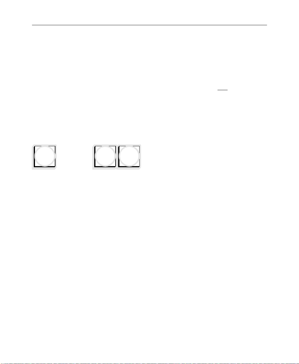
Section 2 — Control Panel Descriptions
All buttons on the Source Select panel have three levels of
illumination, known as “tally”:
■ OFF indicates not selected
■ DIM or “low tally” indicates selected, but not on-air
■ BRIGHT or “high tally” indicates selected and on-air
Only one button in each row is illuminated at any time (not
including the SHIFT button).
Primary Source Selection (Primary Crosspoints)
Each row of primary source selection buttons consists of 16
buttons for the 3000-2 or 24 buttons for the 3000-2, each having a
BLACK
...
BKGD1BKGD
customer-specified designation under a clear lens cap.
Each input, including BLACK and BKGD, can be mapped to any
vertical column of source select (“crosspoint”) buttons. Thus, each
column of buttons may be visualized as an input bus of video and
key crosspoints.
2
2-10
External video and key inputs connected to the switcher are
numbered 1 through 64. Each input can be treated as either a video
signal or a key signal, as defined in the Configuration menu.
For the 3000-2, up to 32 video/key pairs may be assigned at one
time to the crosspoint buttons — 16 “unshifted” and 16 “shifted”
selections. For the 3000-3, up to 48 video/key pairs may be
assigned at one time to the crosspoint buttons — 24 “unshifted”
and 24 “shifted.”
On each column of crosspoint buttons, you can map a video
signal, a key signal, and a chroma key signal. The video and
luminance keys can be any combination of external video,
external key, and a variety of internal signals.
When you press the crosspoint button at the intersection of the
column and the row, the appropriate signal on each input column
is switched onto any output bus (horizontal row)—the mapped
key signal onto the selected key bus or the mapped video signal
Page 43

SHIFT
Source Selection
onto the selected video bus (Background A, Background B,
Program, or Preset).
Any video or key input may be selected on any number of output
buses; however, only one output signal may selected at one time
on each output bus.
The SHIFT button located at the right end of each primary source
selection row is used to access the 16 or 24 shifted inputs. In
Normal mode, you select a shifted input by holding SHIFT down
(button lamp comes on) and pressing a crosspoint button on that
bus. The
selection is a shifted selection.
SHIFT button lamp then remains lit to show that the
NOTE:
In Normal mode (Shift Lock off) the Shift mode will turn off if
another selection is made on that bus without holding down the SHIFT
button. So, even if the SHIFT button is already lit, in order to select
another shifted crosspoint on that bus, you must press and hold the
SHIFT button while selecting the new crosspoint.
Shift Lock Mode
A Shift Lock mode is also available that allows a bus to be held in
the shifted state. This will allow ready access to those input
sources that have been mapped to shifted crosspoints. This mode
is enabled in the Configuration/User Preferences Menu by
selecting LATCH.
When in Shift Lock mode (with the SHIFT button lamp off), to
select a shifted input, press and hold the SHIFT button (lamp
comes on) and press a crosspoint button on that bus. The SHIFT
button lamp then remains lit to show that the selection is a shifted
selection and that the bus is in the shifted state. (So far it looks
pretty much the same as Normal mode). The difference comes
when you select another crosspoint on the same bus. In Shift Lock
mode, whenever the SHIFT button is lit, if you make another
selection on that bus without pressing the SHIFT button, the
2-11
Page 44

Section 2 — Control Panel Descriptions
selection will be a shifted crosspoint, whereas in Normal mode it
would be an unshifted crosspoint.
In Shift Lock mode, to select an unshifted crosspoint, press and
hold the SHIFT button (lamp goes out) and select a crosspoint on
that bus.
NOTE:
button in order to revert to the unshifted state. Simply pressing SHIFT
will not have any effect.
In Shift Lock mode, you must press SHIFT plus a crosspoint
Crosspoint Button Flashing
A primary crosspoint button may flash if the timing of a selected
input cannot be corrected by the automatic input timing circuit.
This flashing caution can be disabled through the Configuration
menu.
2-12
Page 45

Secondary Source Selection (Re-entry Crosspoints)
The secondary source (“M/E re-entry”) buttons, M/E 1,
M/E
1
M/E
2
M/E
3
M/E 2, and M/E 3 (3000-3 only) are located at the right end
of each row of primary crosspoint buttons.
Unlimited re-entry is supported for outputs of the Mix/Effects
(M/Es). The program output of any M/E may be reentered as an
input on any other M/E or in the Flip-Flop Mix/DSK system, or it
may be used as a key source on any other M/E or the DSK.
Since multiple re-entry is allowed, lockout logic prevents one
M/E from entering another M/E at the same time the other M/E
is entering the first. If a circular re-entry is attempted, the request
for the second re-entry will be ignored.
Uncal Indicators
Source Selection
UNCAL
Each UNCAL indicator LED, located in line with a row of source
select buttons, lights if one or more of the following variables are
set to non-default values for the selected crosspoint on that bus:
opacity, luminance gain, chroma gain, dc offset, coring, or
horizontal key position.
Key Delegation Indicators (Model 3000-2 Only)
KEY 1
KEY 2
The KEY 1 and KEY 2 indicator LEDs, located adjacent to the
reentry source selection buttons and in line with each row of key
crosspoint buttons, light to indicate which keyer the row of
buttons is currently delegated to control.
2-13
Page 46

Section 2 — Control Panel Descriptions
Transition Subpanels
A Transition subpanel is supplied for each M/E and for the PGMPST/DSK mixer (see Figure 2-4 and 2-5). Controls common to all
Transition subpanels are: a lever arm for manual transitions;
transition direction indicators; CUT, AUTO TRAN, and PST BLK
buttons; and a three-digit LED display that shows the auto
transition duration in frames.
EFF
EFF
SEND
SEND
BKGD
BKGD
B
LAYERED
A
ONON
EFF
SEND
KEY
ON
OVER
1
TRANSITION
EFF
SEND
KEY
KEY
PRIOR
2
ON
OVER
TP0348-08
PST
BLK
060
CUT
WIPEMIX
AUTO
TRAN
Figure 2-4. Mix/Effects Transition Subpanel
TRANSITION
DSK
DSK
BKGD
OVER
CUT
1
ON
AUTO
TRAN
2
ON
OVER
PST
BLK
060
Figure 2-5. DSK Transition Subpanel
TP0348-09
2-14
Page 47

Next Transition Buttons
The five next transition buttons in each M/E—BKGD B, BKGD A,
KEY 1, KEY 2, and KEY PRIOR—select the M/E output signals that
will change during the next transition.
The three next transition buttons in the PGM-PST/DSK—BKGD,
DSK 1, and DSK 2—similarly select the PGM-PST output signals
that will change during the next transition.
Transition Subpanels
ONON
EFF
An ON indicator located beneath each key next transition button
is lit when the associated signal is an active part of the M/E
output.
NOTE:
The way the M/E Next Transition buttons operate depends on
whether the M/E is operating in Standard Mode or in Layered Mode. The
mode of operation is set in the M/E MODE menu, described in the next
section of this manual.
The EFF (Effects Send) indicator located above each key next
transition button is lit when the associated keyer output is
selected as an effects send output by one of the AUX 1-4 EFFECTS
SEND ONLY
M/E Next Transition Buttons (
buttons.
Standard Mode
)
In Standard Mode, only the BKGD A, KEY 1, KEY 2, and KEY PRIOR
next transition buttons and the ON and OVER indicators below the
KEY buttons are functional. (The BKGD B button and the ON
indicators below the BKGD buttons are not functional and the
LAYERED indicator is not lit.)
The transition can affect Background only, Key 1 only, Key 2 only,
Key Priority only, or any combination thereof. Multiple-layer
transitions are selected by simultaneously pressing more than one
button.
2-15
Page 48

Section 2 — Control Panel Descriptions
Pressing BKGD A selects background video to change during the
BKGD
A
next transition. That is, the background video output of the M/E
will change from the source selected on the A Background bus to
the source selected on the B Background bus.
At the end of the transition, the inputs selected on the background
buses will interchange, or “flip-flop.” The “new video” on the B
Background bus will transfer to the A Background bus, and the
“old video” on the A Background bus will transfer to the B
Background bus.
KEY
1
KEY
2
KEY
PRIOR
OVER
LAYERED
Activating the KEY 1 or KEY 2 button (lamp lit) causes the next
transition to bring on or remove the selected key. Selecting KEY 1
or KEY 2 delegates the M/E Keyers subpanel and Key bus to the
selected keyer so that the characteristics of that key may be
adjusted (see Keyer subpanel description).
One or both of the KEY buttons can be activated at the same time
and one or both keys can be on (ON indicator lit) at the same time.
Pressing KEY PRIOR causes the next transition to swap the
Key 1/Key 2 priority . This can be performed as a mix, wipe, or cut
transition. Key priority always involves both Key 1 and Key 2
The OVER indicator indicates whether Key 1 is over Key 2, or Key
2 is over Key 1. (The key whose OVER indicator is lit is over the
other key.)
M/E Next Transition Buttons (
Layered Mode
)
In Layered Mode, all of the next transition buttons and indicators
are functional and the LAYERED indicator is lit. In this mode,
BKGD B and BKGD A are keyers.
The transition can affect Background A only, Background B only,
Key 1 only, Key 2 only, Key Priority only, or any combination
thereof. Multiple-layer transitions can be selected by
simultaneously pressing more than one button.
2-16
Page 49

Transition Subpanels
NOTE:
mode. Operating in layered mode causes the A and B Backgr ound layers
to transition in a manner similar to the Key 1 and Key 2 layers (see the
descriptions for Key 1 and Key 2).
BKGD
B
BKGD
A
In Layered mode, the BKGD A and BKGD B buttons also delegate
the keyers subpanel. (The key bus delegation remains unchanged
when the keyer subpanel is delegated to either of the background
layers.)
PGM-PST/DSK Next Transition Buttons
BKGD
DSK
1
DSK
2
Transition Type Buttons
The type of transition at the next transition is determined by the
WIPE
Flip-flop operation occurs only when operating in Standard
The PGM-PST/DSK next transition buttons function the same
as the M/E next transition buttons in Standard Mode, except
that there is no
BKGD, DSK 1, and DSK 2 buttons correspond to the M/E
BKGD A, KEY 1, and KEY 2 buttons.)
KEY PRIOR button. (The PGM-PST/DSK
, MIX, and PST BLK buttons.
WIPE
MIX
The WIPE and MIX buttons are mutually exclusive; pressing one
selects it and de-selects the other.
A WIPE transition uses the output of the wipe generator to shape
the selected transition(s). Y our selected wipe pattern appears over
the old video/key and moves across the screen, revealing the new
video/key as it moves. Use either the lever arm or the AUTO TRAN
button to perform the WIPE transition.
Pressing MIX selects a transition that mixes video, keys or
backgrounds, during the change from one source to the other. A
mix transition gradually fades the new video and/or key over the
old video and/or key. You can use either the lever arm or AUTO
TRAN
button to perform a MIX transition.
2-17
Page 50

Section 2 — Control Panel Descriptions
Pressing the PST BLK button selects a two-stage transition that
PST
BLK
inserts black between the two video sources being mixed, wiped,
or cut. For example, instead of mixing directly between the A
Background and B Background buses during a background
transition, a preset black transition mixes, wipes, or cuts from the
A Background bus to black. When a second transition is
performed, black mixes, wipes, or cuts, away to the B Background.
After completion of the two transitions, PST BLK turns itself off
automatically.
In addition to this automatic cancellation, you can toggle PST BLK
on and off manually. If you turn off PST BLK while the transition
is on the black limit, the M/E or PGM-PST output will
immediately switch from black to the original signal. If you turn
off
PST BLK when it is off limit, the transition to or from black will
stop.
The PST BLK function is provided in each M/E and in the PGM-
PST mixer . PST BLK affects only the ef fect wher e it is selected and
not the entire switcher. The button lights when pressed and turns
off automatically when the second transition is complete. The
BLACK
video input button on the A Bus remains lit while the M/E
is on the black limit. The preview output for the M/E does not go
to black. The preview monitor continues to show the final result of
the two-stage preset black transition.
2-18
MIX and WIPE are unaffected when PST BLK is turned on. MIX and
WIPE
can be changed at any time during a preset black operation.
Preset Black always fades to a full screen black regardless of
whether the switcher is operating in layered mode or standard
mode.
An abort of Preset Black occurs when the operator selects a
crosspoint on the A Background bus while the M/E transition is
on the black limit. This abort causes the following to occur: the
preset black transition is cancelled, the PST BLK button lamp turns
off, all keys are dropped, and the selected cr osspoint is taken fully
on-air. If the abort occurs in Layered Mode, the M/E is forced to
Standard Mode to ensure that the selected crosspoint is a full
raster image.
Page 51

BLACK
Transition Subpanels
A new background source may be selected on the B Background
bus when you are at the midpoint of a preset black mix. In the
same manner , next-transition delegation buttons, keyer modes, or
keyer sources may also be changed. None of these changes will
abort the preset black transition.
Configuring the BLACK Crosspoint — When mapping inputs to
pushbuttons, one of the choices in the Configuration menu is
BLACK, and another choice is NONE. Your selection will have an
effect on how PST BLK operates, and what will happen in the
event the controller CPU fails.
When the first transition during a preset black operation is
completed, the BLACK crosspoint is automatically selected on the
A Background bus. If black has not been assigned to any
pushbutton, the PST BLK button is disabled and the preset black
function is not permitted. On the other hand, if black has been
assigned to more than one pushbutton, preset black will select the
leftmost BLACK pushbutton. If a pushbutton is assigned to
black appears when that button is selected; however the preset
black function will not use this as the BLACK crosspoint. This
action permits the user to have a known signal appear when an
undefined pushbutton is pressed, while also allowing the preset
black function to select a specific BLACK crosspoint.
NONE
,
To summarize operation: if the user has
NONE
assigned to one or
more pushbuttons, but does not have black assigned to any
pushbutton, the preset black function will think black is not
available and will be disabled as described above.
Processor Failure—The BLACK crosspoint is also important in the
situation where the Controller main CPU fails while one of the
M/Es is performing a re-entry. When it fails, the M/Es are
required to abandon their re-entry crosspoints and select BLACK
on the same bus. In the case where black was never assigned to a
pushbutton, the M/E selects the leftmost crosspoint on the bus.
2-19
Page 52

Section 2 — Control Panel Descriptions
Transition Controls
AUTO
TRAN
CUT
Y ou can perform a transition using any of thr ee differ ent controls:
the lever arm, the AUTO TRAN button, or the CUT button.
The lever arm is used to perform “manual” transitions. The BKGD
B
, BKGD A, KEY 1, KEY 2, KEY PRIOR buttons, or any combination
thereof, can be delegated to the lever arm to perform the transition.
You can move the lever arm in either direction due to the flip-flop
architecture of the buses. Moving the lever arm from one limit to
the other always performs a complete transition.
Using the lever arm, it is possible to start a transition, stop it at
any point, reverse it, and even return to the original limit,
without completing the transition. The green arrow at the top
or bottom of the
lever arm travel lights to indicate the direction
that the lever arm has to move to complete the transition.
You can use the lever arm in combination with the AUTO TRAN
button to perform a transition. You can start the transition by
moving the lever arm off its limit, and finish the transition by
pressing AUTO TRAN. The transition is completed at a rate
proportional to the rate set for a full AUTO TRAN transition. For
example, if the lever arm is moved halfway and the transition is
completed by pressing AUTO TRAN at a rate of 200 frames, the
remaining half of the transition will take 100 frames.
2-20
NOTE:
The lever arm will be left off-limit any time you begin a
transition with the lever arm and finish it with AUTO TRAN. The lever
arm
will not function properly again until is moved to either limit (this
action will not change the M/E output). While the lever arm is nonfunctional, both lever arm direction indicators are on.
Pressing CUT cannot, however, complete a transition begun with
the lever arm. In this case, CUT reverses the inputs during the
background transitions. During key transitions, it changes the
logic state of the key.
Page 53
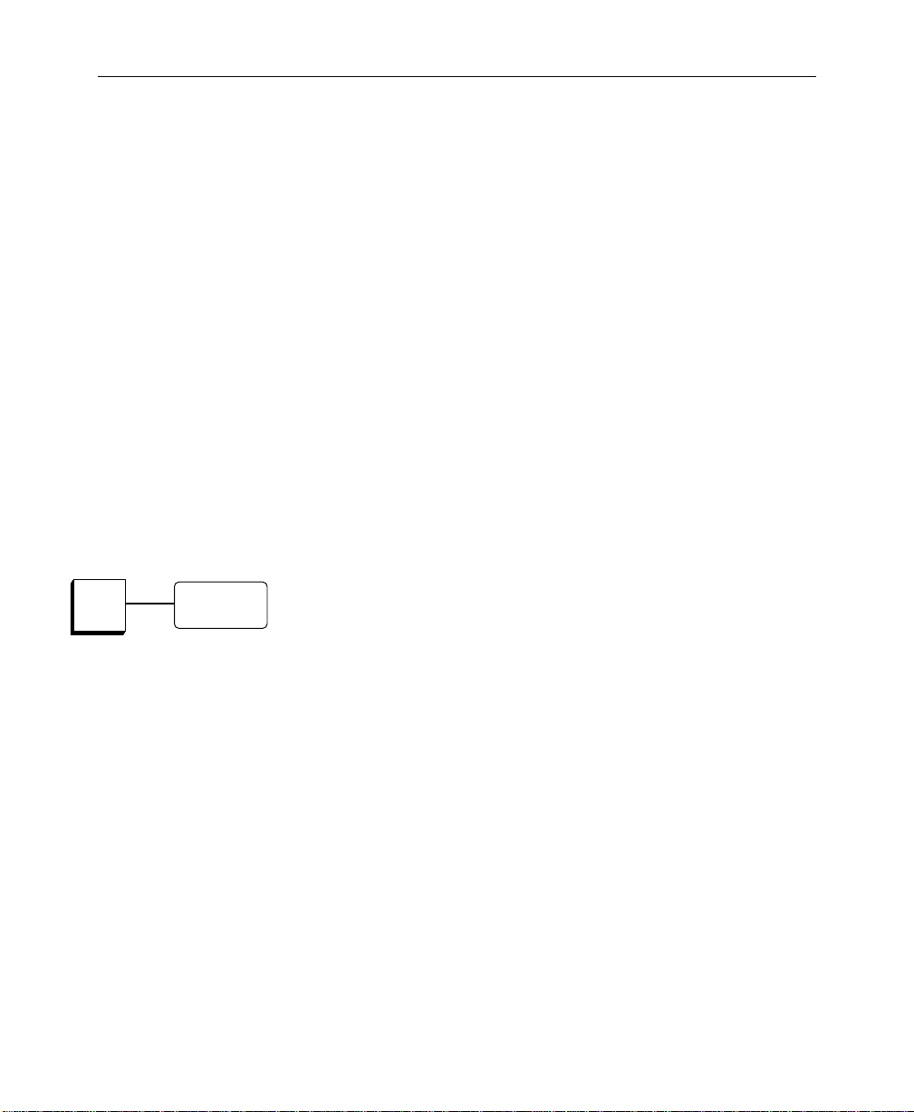
Transition Subpanels
E-MEM recall operations result in another set of conditions for
lever arm transitions. When an E-MEM recall places a transition at
a point different from that of the lever arm, the lever arm becomes
inactive until it is moved to catch up with the transition. For
example, assume the lever arm is on a limit and an E-MEM recall
puts the transition at some midpoint. In such a case, the lever arm
would be inoperative until you moved it far enough to catch up
with the transition. At that point, you could use the lever arm to
complete the transition or return it to the beginning limit. (Or , you
could press AUTO TRAN to complete the transition). Another
example of use with E-MEM is a case where the lever arm is off
limit and an E-MEM recall puts the transition on a limit. In this
instance, both lever direction lights would be lit, indicating the
lever arm is inoperative. Moving the lever arm to either limit will
turn the direction lights off and reactivate the lever arm. (You
could also use AUTO TRAN to resume the transition since auto
transitions continue to function even when the lever arm is
inoperative.)
AUTO
TRAN
060
Pressing the AUTO TRAN button starts an automatic S-linear
transition at the rate displayed on the LEDs next to the button. The
AUTO TRAN
BKGD B
thereof.
You can specify a transition rate by entering a value from 0 to 999
frames on the numeric keypad on the Effects Memory subpanel. A
zero frame transition is equivalent to a cut. (Refer to the M/E and
Master Effects Memory subpanel descriptions later in this section
for further information on setting the rate.) The lamp in the AUTO
TRAN
Pressing AUTO TRAN a second time during a transition, stops the
transition at the current point. The transition can be completed by
pressing the button a third time or by moving the lever arm to its
opposite limit. The lever arm becomes active when it catches up
with the auto transition in progress. Pressing the CUT button
leaves the transition where it stopped but reverses the two videos
or the logic state of a key. Similarly, you can start a transition by
using the lever arm and complete it by pressing the AUTO TRAN
button supports the same transitions as the lever arm:
, BKGD A, KEY 1, KEY 2, KEY PRIOR, or any combination
button remains lit for the duration of the transition.
2-21
Page 54

Section 2 — Control Panel Descriptions
button. However , performing a transition in such a manner leaves
the lever arm off limit.
M/E
Trans
KEY 1
CUT
KEY 1
MIX
KEY 2
CUT
KEY 2
MIX
CUT
DSK
Trans
DSK 1
CUT
DSK 1
MIX
DSK 2
CUT
DSK 2
MIX
Pressing the CUT button causes an immediate transition. The M/E
or PGM-PST output changes instantaneously. (The CUT button
lights for one-half second.) The CUT button supports the same
transitions as the lever arm: BKGD B, BKGD A, KEY 1, KEY 2, KEY
PRIOR
, or any combination thereof.
Key Transition Buttons (3000-3 Only)
The four key transition buttons at the right edge of each transition
panel provide a quick way of doing a simple cut or mix on any
keyer in that M/E or DSK.
Pressing the
T ransition subpanel cuts the corr esponding key ON if it was OFF,
or OFF if it was ON, as indicated by the ON LED under the next
transition button for that key. Similarly, pr essing the KEY 1 MIX or
KEY 2 MIX
ON.
Pressing the DSK 1 CUT or DSK 2 CUT button on the DSK
T ransition subpanel cuts the corr esponding key ON if it was OFF,
or OFF if it was ON; pressing the DSK 1 MIX or DSK 2 MIX button
mixes the key ON if it was OFF, or OFF if it was ON.
KEY 1 CUT or KEY 2 CUT button on the M/E
button mixes the key ON if it was OFF, or OFF if it was
2-22
Page 55

Transition Subpanels
Key Mix Rates
The mix rates used by the KEY 1 MIX and KEY 2 MIX buttons on the
M/E Keyer panels are independently programmable, as detailed
under the E-MEM panel TRAN RATE button description. After the
M/E keyer mix rate has been programmed for each button, the
rate is shown in the T ransition panel r eadout only while the mix is
in progress or while the SHOW KEY button on the Keyer or DSK
panel is being pressed.
The mix rates used by the DSK 1 MIX and DSK 2 MIX buttons at the
right edge of the PGM-PST/DSK Transition panel are similarly
independently programmable, but those rates may also be used as
auto transition rates by the
PST/DSK Transition panel.
DSK Key Transition Rates
When an auto transition is done on the PGM-PST/DSK T ransition
panel, all transitions (BKGD, DSK 1, and/or DSK 2) take place at
the same rate. What that rate is depends on what transitions are
enabled at the time, with the programmed rate for the left-most
enabled button taking precedence.
DSK 1 and DSK 2 buttons on the PGM-
In other words, if a BKGD transition is enabled (BKGD button lit),
the auto transition rate will be the rate displayed in the readout on
the Transition panel. However, if BKGD is not enabled, the auto
transition rate will be the programmed rate for the leftmost DSK
button—DSK 1 if it is enabled, or DSK 2 if that is the only enabled
transition.
2-23
Page 56

Section 2 — Control Panel Descriptions
Mix/Effects Effects Memory Subpanel (3000-3 Only)
The Effects Memory (E-MEM®) subpanel for each M/E (see
Figure 2-6) allows you to learn and recall effects setups for the
mix/effects system in which the subpanel resides. It also provides
effects dissolves and sequences between effects stored in its own
registers.
Refer to the Master Effects Memory subpanel description, later in
this section, for a description of the use of the mix/effects E-MEM
panels when controlled by Master E-MEM to produce the overall
output of the switcher.
NOTE:
Much of the following information is repeated in the description
of the Master E-MEM panel; however , it is included here so that you can
see the differences between the operation of the mix/effects E-MEM panel
and that of the Master E-MEM keypad and readout.
EFFECTS MEMORY
TP0702-25
LOCK
LRN
SEQ
EFF
DIS
BANK
NO REG
7
8
5
4
1
UNDO
0
•
9
6
32
TRAN
RATE
RUN
BANK
0
BANK
1
ENTER
Figure 2-6. Mix/Effects E-MEM Subpanel (3000-3 Only)
2-24
Page 57

Mix/Effects Effects Memory Subpanel (3000-3 Only)
Learn and Recall Operations
Effects setups are stored in E-MEM registers. The following
parameters are learned and recalled in learn/recall operations on
the mix/effects E-MEMs: standard or layered mode operation,
crosspoint settings, transition settings, keyer settings, masks and
mattes, chroma key settings, wipes, positioner settings and full
additive mix (FAM) settings.
E-MEM Registers
There is a total of 100 registers in each mix/effects E-MEM,
grouped in ten banks of ten registers. Each register belongs to a
specific bank (0 through 9) and has a unique number (0 through 9)
within that bank. For example, register 46 means bank 4,
register 6.
When the system is powered up, the keypad readout comes up
with a “NO REG” message.
Learning Effects
To learn an effect setup into a register, press the following
sequence of buttons on the E-MEM subpanel:
LRN, BANK, bank number, register number
NOTE:
BANK
Also, if the desired bank is 0 or 1, you may substitute
for
If the next desired register is in the current bank, you may omit
and
bank number
BANK, bank number
in the above sequence.
BANK 0
in the above sequence.
or
BANK 1
2-25
Page 58
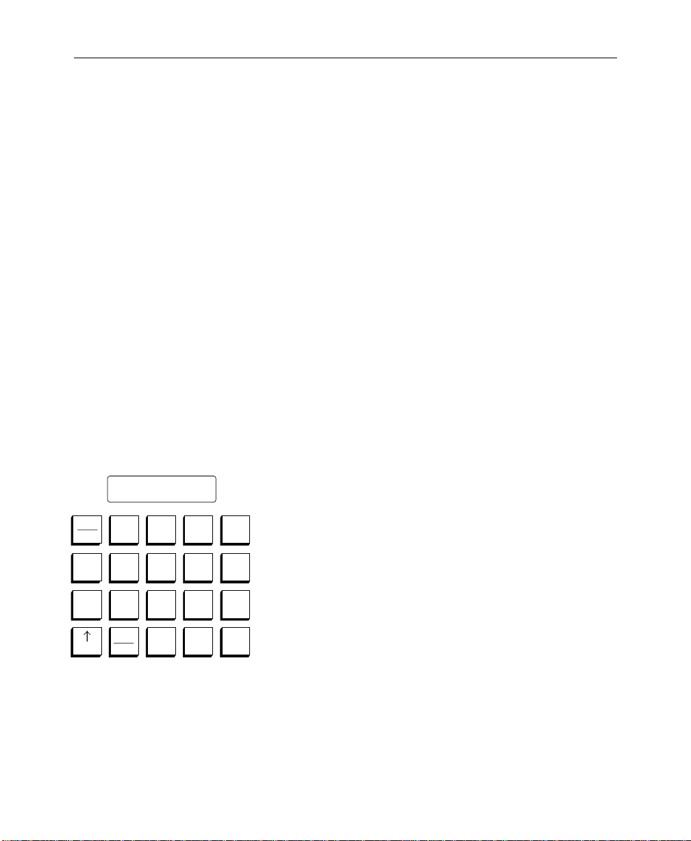
Section 2 — Control Panel Descriptions
Recalling Effects
To recall a register, press the following buttons:
BANK, bank number, register number
(The previous
When an E-MEM register is recalled, the key memory for any
recalled crosspoint is updated.
Crosspoint Override
During an E-MEM recall, if you don’t want the crosspoint to
change, you can manually hold down the present crosspoint
button while the E-MEM register is recalled. If key memory is off
at this time, the video and key crosspoint are held. If key memory
is on, the video and key crosspoint and the current keyer memory
state are held.
Mix/Effects E-MEM Keypad
NO REG
LOCK
LRN
SEQ
EFF
DIS
BANK
7
4
1
UNDO
•
8
5
0
9
32
TRAN
RATE
RUN
BANK
6
0
BANK
1
ENTER
NOTE
for learning applies also to recalling.)
In addition to learning and recalling effects, the
E-MEM keypad is used as a numerical entry pad for
the following buttons: TRAN RATE, LRN, LRN SEQ,
LOCK
, and BANK.
Pushing a numerical button at any time other than
when preceded by one of the above buttons recalls
the corresponding register within the current bank.
T o r ecall a r egister in a differ ent bank, enter the r ecall
sequence described on the previous page.
2-26
Page 59
L B0 R04
BANK
Mix/Effects Effects Memory Subpanel (3000-3 Only)
Mix/Effects E-MEM Readout
The alphanumeric readout at the top of the E-MEM keypad
provides status information about E-MEM operations and
registers.
During normal learn and recall operations, the display informs
you what the current Bank (“B...”) and Register (“R...”) are. If the
register is locked, there is an “L” shown at the left end of the
display. Other messages on the E-MEM readout include “NO
REG” at bootup, and “NO EMPTY” if no register is available for a
LRN •
operation.
≠/BANK is a two-function key that can be used for bank selection
or for accessing “second” functions, for example, LOCK and
UNDO
. Pressing the ≠/BANK button enables single-digit bank
selection (0 through 9) on the keypad, and delegates buttons with
second functions to the second function. The button lights when
pressed, and stays lit until the delegation is completed. Pressing
↑/BANK
a second time terminates the delegation.
BANK
LOCK
LRN
LOCK
LRN
Refer to the “Learn and Recall Operations” description earlier in
this section for use of the BANK button, and to the LOCK and
UNDO headings for use of the ↑ (second) function button.
LRN is used for storing or “learning” the current panel setup into
a register or for learning a register sequence.
Refer to the “Learn and Recall Operations” description earlier in
this section for learning effects into E-MEM registers. Also refer to
the SEQ button description for learning a register sequence.
The LOCK function locks a single register. Locking a register
prevents the contents of that register from being changed. To lock
the current register whose number is displayed, press the
following buttons:
≠, LOCK
2-27
Page 60

Section 2 — Control Panel Descriptions
When locked, an “L” is displayed at the left end of the
E-MEM readout. To unlock the register, press the buttons again:
≠, LOCK
BANK
0
BANK
1
TRIM
ENTER
SEQ
NOTE:
You cannot lock an entire E-MEM bank from the subpanel; a
menu selection is provided for this action.
Pressing the BANK 0 button makes bank 0 the current bank, and
causes buttons 0 through 9 on the keypad to become one-button
recall registers for registers 00 through 09. This button is lit
whenever bank 0 is the current bank.
Pressing BANK 1 makes bank 1 the current bank, and causes
buttons 0 through 9 on the keypad to become one-button recall
registers for registers 10 through 19. This button is lit whenever
bank 1 is the current bank.
ENTER confirms a numerical entry on the keypad, such as for
TRAN RATE. The ENTER button lights only when pressed.
SEQ is used for creating automated register-recall sequences.
Sequences are created by pressing the following buttons
(parameters in parentheses are optional):
2-28
SEQ, LRN,
register, TRAN RATE, delay,
register, TRAN RATE, delay,
...
Page 61

Mix/Effects Effects Memory Subpanel (3000-3 Only)
NOTE:
SEQ
and LRN may be pressed in either order to start the
command sequence;
TRAN RATE
TRAN RATE
and delay, in parentheses, are optional.
enables a user-defined delay to be introduced between
register recalls;
delay
is a 1- to 3-digit number entered on the keypad that specifies an
amount of delay in TV frames. (If the number entered is a 1- or 2-digit
number, the entry must be terminated by pressing
register
BANK, bank number, register number).
is any desired register number, as described previously (that is,
ENTER;
A sequence loop may be cr eated by again pressing the first register
button as the last register in the sequence.
Sequences are initiated by pressing the following buttons:
SEQ, register
The sequence starts at the register indicated, and proceeds
through the linked sequence to the last register. If a loop has been
programmed, the sequence loop continues until the SEQ button is
pressed to terminate the sequence.
A sequence loop can be broken by double-pressing a register
button. This clears the sequence link that existed in that register
and makes that the last register in the sequence.
EFF
DIS
Different sequence delays may be learned into the different
mix/effects E-MEM registers. W ith softwar e version 3.1 and later,
these sequence delays are completely independent; thus the
sequencing may be occurring at different times on the different
M/Es.
EFF DIS causes an S-linear transition from the current state to the
next recalled register. The current state may be a setup you have
just done on the mix/effects panel or the state of the panel
resulting from a register recall.
2-29
Page 62

Section 2 — Control Panel Descriptions
An effects dissolve may be learned into a register , so that r ecalling
that register will initiate a dissolve to another specified register.
The following button sequence is used to learn a dissolve
(parameters in parentheses are optional):
LRN, EFF DIS, (TRAN RATE, eff dissolve rate), register
NOTE:
LRN
and
EFF DIS
may be pressed in either order to start the
command sequence;
TRAN RA TE
enables a user-defined effects dissolve rate to be introduced
in the dissolve;
eff dissolve rate
is a 1- to 3-digit number entered on the keypad that
specifies the effects dissolve rate in number of TV frames. (If the number
entered is a 1- or 2-digit number, the entry must be terminated by
pressing
register
BANK, bank number, register number
ENTER);
is any desired register number, as described previously (that is,
).
The effects dissolve rate is the same as the auto transition rate
indicated in the readout on the Transition subpanel of that M/E.
When the register with the learned effects dissolve is recalled, the
EFF DIS button high tallies, turning off when the dissolve ends.
Different sequence delays may be learned into the different
mix/effects E-MEMs. With software version 3.1 and later, these
sequence delays are completely independent; thus the sequencing
may be occurring at different times on the different M/Es.
As with sequence delays, the effects dissolve rates on different
mix/effects are completely independent. Differ ent effects dissolve
rates may be learned separately into different mix/effects EMEMs; thus the dissolves may be running at different rates on the
different M/Es.
2-30
UNDO
•
The • (dot button is used to represent the next empty register when
used with the LRN operation. (At register 99, the search for an
empty register will wrap around to 0).
Page 63
Mix/Effects Effects Memory Subpanel (3000-3 Only)
LRN • learns the current switcher state into the next empty
register, and that register becomes the current register.
BANK
UNDO
•
TRAN
RATE
NOTE:
If there are no empty registers, the operation will not be done,
an error beep will sound, and the keypad readout will show “NO
EMPTY.”
UNDO is used to back out of a recall, learn, or another UNDO
register operation. The UNDO button lights when pressed,
confirming that it has been pressed. An UNDO must be done
immediately after an undesired operation, otherwise it may not be
able to undo the operation.
For these register functions, pressing ↑, UNDO repeatedly allows
you to toggle back and forth between the two last states. (For
toggling UNDO, you have to press ↑/BANK then UNDO each time.)
TRAN RA TE is used with the keypad to set the transition/mix rates
used by the AUT O TRAN (auto transition) and KEY MIX buttons on
the Transition subpanels, and by the EFF DIS button on the M/E
E-MEM keypad.
When TRAN RA TE is pressed, the E-MEM readout displays the
currently set auto transition rate, for example:
AUTO:030
To change the auto transition rate for that M/E, enter the desired
rate using the number buttons on the M/E E-MEM keypad.
Pressing three number buttons on the keypad automatically
enters the rate. If only one or two number buttons are pressed, the
entry must be completed by pressing ENTER. Rates from zero
through 999 frames may be entered. (If one or two incorrect
number keys have been pressed, the entry may be aborted and the
previous rate restored by pressing TRAN RATE again.)
As soon as the new rate is confirmed, it is displayed in the auto
transition rate display on the T ransition subpanel and the E-MEM
readout will then display the Key 1 mix rate, for example:
2-31
Page 64

Section 2 — Control Panel Descriptions
KEY1:060
This display refers to the mix rate of the KEY 1 MIX button at the
right edge of the Transition panel. To change the Key 1 mix rate,
follow the same procedure as described above for the auto
transition rate.
As soon as the new rate is confirmed, it is entered into memory for
that M/E, but is not displayed. The readout then displays the
third transition/mix rate:
KEY2:060
Repeat the procedure again to set the mix rate for the KEY 2 MIX
button.
RUN
NOTE:
readout when the
a mix) or when the
enabled (
The mix rate for either key is displayed on the auto transition
KEY 1
KEY 1 MIX
SHOW KEY
or
KEY 2
or
KEY 2 MIX
button is pressed (initiating
button is pressed and the desired key is
button on Keyer panel lit).
Any of the three transition/mix rates can be skipped simply by
pressing the ENTER button when the display appears.
When the sequence of transition/mix rates has been completed,
the TRAN RA TE button turns off and the keypad display returns to
its previous state.
The RUN button on the M/E E-MEM panel is non-functional at
this time.
2-32
Page 65

Keyer Subpanels
Keyer Subpanels
One Keyer subpanel is provided for each M/E, and one Keyer
subpanel serves the two Downstream Keyers (see Figure 2-7 and
Figure 2-8).
KEYERS
NORM
KEY
OVER
VIDEO
FILL
LIN
KEY
KEY
ON
BORD
INH
MASK
MATTE
FILL
LUM
KEY
BKGD
B
SHDW
FORCE
MASK
SPLIT
KEY
CHR
KEY
BKGD
A
EXTD
INV
VIDEO
KEY
PRI
PST
PTTN
KEY
1
OUT
LINE
SHOW
KEY
AUTO
SEL
KEY
SEC
PST
PTTN
KEY
2
BORDERLINE
SIZE / POS
BORDERLINE
OPACITY
GAIN
CLIP
Figure 2-7. Mix/Effects Keyers Subpanel
DOWNSTREAM KEYERS
OUT
NORM
KEY
OVER
VIDEO
FILL
LIN
KEY
BORD
INH
MASK
MATTE
FILL
LUM
KEY
SHDW
SPLIT
KEY
EXTD
INV
VIDEO
KEY
LINE
SHOW
KEY
AUTO
SEL
KEY
BORDERLINE
SIZE / POS
BORDERLINE
OPACITY
GAIN
TP0702-10
TP0702-11
KEY
ON
2
1
CLIP
DSK
DSK
Figure 2-8. Downstream Keyers Subpanel
2-33
Page 66

Section 2 — Control Panel Descriptions
The Keyer subpanels provide control over the following features
for a specified M/E or DSK:
■ Key masking
■ Video key type selection—preset pattern, chroma key,
luminance key, or linear key. (The DSK has only luminance
and linear keys.)
■ Key fill: matte or video fill
■ Key source: video key or auto-selection of key signals based
on user preferences
■ Show key on Switched Preview monitor
■ Borderline settings
■ Key invert
■ Key priority
■ Clip and Gain
Keyer Delegation
KEY
1
BKGD
B
DSK
1
2-34
KEY
BKGD
A
DSK
2
In standard mode, the Keyer subpanel located in each M/E row
2
can be delegated between Key 1 and Key 2.
KEY
1
KEY
2
In layered mode, four keyers are available—Key
1, Key 2, Background B, and Background A.
The Downstream Keyer subpanel can be delegated to DSK 1 or
DSK 2.
Page 67

KEY ON Indicator
Keyer Subpanels
KEY
ON
Key Type Buttons
LIN
KEY
LUM
KEY
CHR
KEY
LIN
KEY
CLIP
GAIN
The KEY ON indicator lamp displays whether the delegated keyer
is in use or not. This indicator is a logical AND of the ON indicator
in the transition subpanel and the keyer delegation selection.
PRI
PST
PTTN
SEC
PST
PTTN
The second row of buttons from the bottom
of each Keyer subpanel selects one of five
keyer modes.
Pressing the LIN KEY button selects a linear key with a gain fixed
at unity, clip fixed at 50%, and no S-shaping. The LIN KEY lamp
(only) is illuminated when this linear key is selected.
If a linear key is desired, but the key signal is not at the correct
level, adjustments can be made with the CLIP and GAIN knobs.
CLIP adjusts the offset of the key signal (over a small range) in
linear key mode. GAIN adjusts the amplitude of the key signal
(over a small range).
If either knob is adjusted away from unity, the LUM KEY button
lights in addition to the LIN KEY button lamp. When both buttons
are illuminated, that indicates to the operator that a linear key is
being performed with non-unity gain and/or clip. If key memory
is on, the non-unity clip and gain settings are recalled whenever
the input associated with these settings is selected.
LUM
KEY
When gain and clip are returned to unity, the LUM KEY button
lamp goes off. Because it is difficult to adjust the knobs back to
exact unity , provision is made to for ce the unity values by pressing
the LIN KEY button a second time while the button is lit. This
action restores unity and turns off the LUM KEY button lamp.
The LUM KEY button selects a luminance key that has variable clip
and gain adjustment and S-shaping of the key signal. Key CLIP
(offset) and GAIN (amplitude) settings are remembered for each
source on each keyer when key memory is enabled via the
2-35
Page 68

Section 2 — Control Panel Descriptions
software menu. The CLIP control has enough range to clip down
to superblack.
A menu selection is available that switches a chr oma trap into the
key path to remove unwanted chroma from video used for
keying.
CHR
KEY
PRI
PST
PTTN
Pressing the CHR KEY button delegates the Chroma Keyer
subpanel to that M/E. (The CHR KEY button is functional only
when the chroma keyer option is installed.) Refer to the Chroma
Keyer subpanel description later in this section for details on
chroma keyer operation. CHR KEY does not function with
background keyers (layered mode), and is not available on the
DSKs.
Pressing the Primary Preset Pattern
PRI PST PTTN button selects
the output of the primary (transition) wipe generator as the key
source. Pattern adjustment is provided by the W ipe subpanel (see
the Wipe subpanel description later in this section for details). The
key CLIP and GAIN knobs are non-functional when this mode is
selected.
In the signal path through the Model 3000 switcher, keys,
including preset patterns, occur before the effect send cr osspoints.
This allows any key, including a preset pattern, to be sent to an
external digital video effects device via an effects send. Transition
wipes, however, occur after the effects send crosspoints.
After pressing PRI PST PTTN, the VIDEO KEY and AUTO SELECT
KEY
functions are ignored and the SPLIT KEY indicator is turned
off; however the VIDEO KEY and AUTO SELECT KEY buttons and
lamps continue to operate.
2-36
NOTE:
Double-pressing the
PRI PST PTTN
or
SEC PST PTTN
button
in the Keyer Subpanel opens up a menu that allows you to set the preset
pattern wipe direction. A single pr ess of either the
SEC PST PTTN
button auto delegates the Wipe Subpanel.
PRI PST PTTN
or the
Page 69

Keyer Subpanels
VIDEO
FILL
SEC
PST
PTTN
MATTE
FILL
Pressing the SEC PST PTTN (Secondary Preset Pattern) button
selects the optional secondary wipe generator as the key source.
Operation of the keyer while SEC PST PTTN is selected is similar
to that when PRI PST PTTN is selected.
The secondary wipe generator option provides wipe pattern
selection independent of the primary wipe generator (no
interaction occurs between them). Without the secondary wipe
option, only secondary preset pattern edge attributes are
independent (preset size, softness, soft symmetry, border width,
border matte, border opacity, and normal/reverse).
All pattern controls are present on the Wipe subpanel and Wipe
menus. Refer to the Wipe subpanel description, later in this
section, for a discussion of these controls.
Primary and Secondary Preset Patterns can be used with all
keyers in layered mode. Preset patterns are not available on the
DSKs.
The
VIDEO FILL and MATTE FILL buttons determine whether the
key is filled with key bus video or a locally generated matte. These
buttons are mutually exclusive; pressing one button de-selects the
other. One of the two buttons is always active and illuminated.
VIDEO FILL and MATTE FILL operate independently from the key
source buttons. All keyer modes except the A and B keyers operate
with either video or matte fill.
When the key bus is contributing to the switcher Program output,
pressing MATTE FILL does not low tally the key bus, even though
the key fill video is not visible.
Video fill mode operates with background keyers in layered
mode. When the keyer is delegated to a background layer, the
VIDEO FILL
button is turned on automatically (MATTE FILL is
turned off).
2-37
Page 70

Section 2 — Control Panel Descriptions
Key Source Buttons
VIDEO
KEY
AUTO
SEL
KEY
The VIDEO KEY and AUTO SELECT KEY buttons determine the
source of the key, or “hole cutter.”
Pressing the VIDEO KEY button forces derivation of the key from a
video source. The “video source” is the video selected on the key
bus (for Keyers 1 and 2) or on the background bus (for
background keyers in layered mode only).
If VIDEO KEY and VIDEO FILL are both selected, the result is a selfkey.
Pressing VIDEO KEY while in Chroma Key mode causes an
encoded chroma key, using the fill video as the source for the
encoded chroma keyer.
Pressing the AUTO SEL KEY button forces the key to be derived
from a user-defined source.
User preferences selected in the Configuration/User Preferences
menu determine whether a luminance or linear key is a self-key or
an external key (and determine which external key is used). They
also specify whether chroma keys are encoded or analog
component (YUV, BETA or RGB).
Split Key Operation
2-38
A Split Key uses any key sour ce other than a key derived from the
key fill (self key) or a key source pre-selected in user preferences
or a preset pattern. Split Keys can be used in all keyers, in either
standard or layered mode.
A Split Key is set up by first selecting the key fill sour ce on the Key
bus, then holding down the VIDEO KEY button or the AUTO
SELECT
button while pressing a second button on the key bus.
The second source provides the key signal. For AUTO SELECT that
key is the external key signal mapped to that column of crosspoint
buttons; for VIDEO KEY the key is the video signal mapped to that
column of crosspoints.
Page 71

Keyer Subpanels
SPLIT
KEY
key, the SPLIT KEY indicator is lit.
Other Key Modifier Buttons
When a split key is operational with an auto select key or a video
KEY
OVER
OVER
INV
Pressing KEY OVER swaps the priority of the two keyers, KEY 1
and KEY 2, regardless of which keyer the subpanel is delegated to.
The KEY OVER button lights when the Keyer subpanel is
delegated to the key that is over the other. It may be pressed
whether or not either keyer is on-air.
In Layered mode, the KEY OVER button does not light if the keyer
subpanel is delegated to either background keyer, but the button
still controls the priority of Keyers 1 and 2. It does not affect the
priority of the background keyers, which have a fixed priority.
One of the two key
subpanel is always on, indicating the priority of Keyers 1 and 2.
The indicator is on regardless of the on-air status of either keyer.
The INV toggle button inverts the polarity of the delegated key
source. Inversion is applied to the incoming key source before key
processing is applied. INV operates in all keyers in layered mode.
OVER indicators on the associated Transition
SHOW
KEY
The SHOW KEY button is used for viewing the key signal on a
particular keyer. This button does not affect the on-air video.
When held down, the Switched Preview bus output shows the key
signal from the keyer currently delegated to the Keyer subpanel.
The key signal displayed is the key after clipping, masking, and
chroma trapping have taken place.
The SHOW KEY button does not affect the program output of the
M/E or DSK, and operates in all keyers in layered mode.
2-39
Page 72

Section 2 — Control Panel Descriptions
Borderline Controls
BORDNORM
SHDW
EXTD
OUT
LINE
The buttons at the top of the Keyer subpanel
control the Borderline option. The NORM,
BORD
, SHDW, EXTD, and OUTLINE buttons
are interlocked; only
one button can be active at a time. Pressing a
button de-selects any other button.
NOTE:
The background keyers (layered mode) do not have Borderline
capability.
Border, Shadow, and Extrude modes operate with video or matte
filled keys. The Borderline matte is separate from the fill matte and
has its own delegate button in the Matte subpanel.
The Borderline matte is adjusted on the Matte subpanel after
selecting K1 BORD or K2 BORD, as appropriate, with the MATTE
SEL
delegation button.
NORM
The NORM button turns Borderline off.
The BORD button turns on symmetrical Borderline mode. The
border width may be one, two, or three video lines wide, as
BORD
adjusted by the SIZE/POS control. (This adjustment is shared with
Outline mode.)
2-40
SHDW
EXTD
The SHDW button turns on Shadow mode. The SIZE/POS knob is
used to adjust the shadow width and position from one to six lines
down and to the to the right or left.
The EXTD (extrude) button operates like SHDW except for the
aesthetic appearance of the shadow effect on the screen. The
shadow width and position adjustments are shared with Shadow
mode.
Page 73

Keyer Subpanels
OUT
LINE
Pressing the OUTLINE button produces an outline of the key
signal. The border width is adjustable to one, two, or three lines.
In Outline mode, there is no fill video or fill matte; only the
background video and outline border matte are output. As a
result, the VIDEO FILL and MATTE FILL buttons have no effect
when OUTLINE is active.
The BORDERLINE SIZE/POS knob adjusts the width of all
Borderline borders. The control also moves the shadow or
BORDERLINE
SIZE/POS
extruded shadow either down to the left or down to the right.
The BORDERLINE OPACITY knob adjusts the transparency of the
Borderline borders.
BORDERLINE
OPACITY
Auto Preview Operation
In normal operation, the Switched Preview output of the system
may be set to monitor any of the M/E preview outputs, DSK
preview output, or preview primary bus.
The Auto Preview featur e is activated by pressing one of the keyer
delegate buttons (KEY 1, KEY 2, BKGD B, or BKGD A) for 1/2
second or longer . When Auto Preview is active, the delegated key
is inserted over the M/E preview or DSK preview output on the
Switched Preview bus so that you may preview the key setup.
Holding down the keyer delegate button or turning the CLIP
and/or GAIN controls prolongs the Auto Preview mode. The
preview returns to normal after the delegate button is no longer
held down and there is no activity on the CLIP or GAIN controls.
2-41
Page 74

Section 2 — Control Panel Descriptions
Mask Control
INH
MASK
FORCE
MASK
The INH MASK and FORCE MASK toggle buttons are illuminated
when turned on, and can be turned on individually or together.
When either button is pressed, the Masks subpanel is
automatically delegated for adjusting the mask, if auto delegation
is enabled.
The background keyers (layered mode) do not have mask
capabilities and the mask buttons are inoperative when the
subpanel is delegated to a background keyer.
Pressing INH MASK inhibits the key from being displayed
wherever the mask is present. (Normally, the mask generator is
used to define areas of the screen where the key is inhibited.)
Pressing FORCE MASK causes the key to be fully turned on where
the mask is present, rather than suppressing the key.
The INH MASK and FORCE MASK buttons are inoperative for
preset pattern keys.
2-42
Page 75
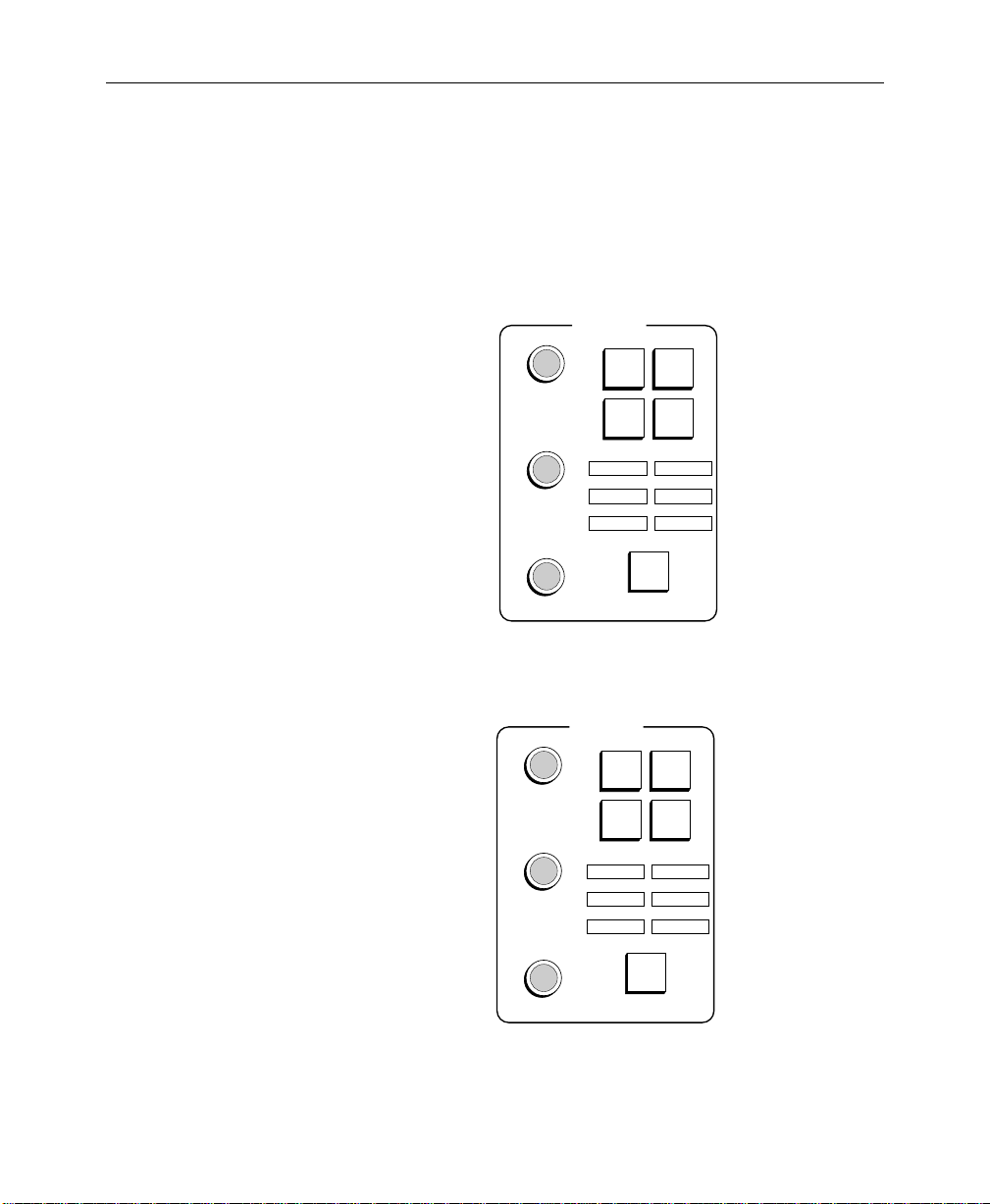
Matte Subpanels
Matte Subpanels
Matte subpanels (Figure 2-9 and 2-10) are provided in each M/E
and the DSK. Controls are provided in the Matte subpanels for
creating and modifying mattes and for assigning the delegation of
the subpanels.
MATTES
PRI
SEC
WIPE
WIPE
WASH
HUE/
SOFTNESS
SATURATION/
OFFSET
BRIGHTNESS
WASH
MATTE
FLAT
MATTE
K1 FILL K1 BORD
K2 FILL K2 BORD
PRI WIPE SEC WIPE
MATTE
SEL
2
0702_13
Figure 2-9. Mix/Effects Matte Subpanel
MATTES
USER
SEC
DEF
WIPE
WASH
HUE/
SOFTNESS
SATURATION/
OFFSET
BRIGHT/TEX
WASH
FLAT
MATTE
MATTE
K1 FILL K1 BORD
K2 FILL K2 BORD
BKGD 1 BKGD 2
MATTE
SEL
2
TP0702-14
Figure 2-10. DSK Mattes Subpanel
2-43
Page 76

Section 2 — Control Panel Descriptions
Matte Delegation
MATTE
SEL
M/E Mattes
Panel
K1 FILL K1 BORD
K2 FILL K2 BORD
PRI WIPE SEC WIPE
Each Matte subpanel has a MATTE SEL button used to select which
of the six matte generators that particular subpanel will control.
Above the MATTE SEL button are six indicators, which illuminate
to show the current delegation at any given time. Pressing the
MATTE SEL
button repeatedly cycles the selection through all six
matte generators. Holding the button down causes it to cycle
through the selections automatically until the button is released. If
the Borderline option is not installed in Key 1 or Key 2, the
K1 BORD and/or K2 BORD selections will be skipped.
MATTE SEL Indicators
The six indicators above the MATTE SEL button indicate
delegation as follows:
K1 FILL and K2 FILL LEDs—Indicate that the Matte subpanel is
delegated to one of the matte generators for an area determined by
the key hole cutter. However, when the keyer is in Video Fill
mode, the matte is not visible. All key types (LIN, LUM, CHR, PST
PTTN) are operational with matte fill.
K1 BORD and K2 BORD LEDs—Indicate that the Matte subpanel is
delegated to a matte generator for adjusting the characteristics of
the key border matte in all Borderline modes. (See the Keyer
subpanel description for related keyer buttons BORD, SHDW,
EXTRUDE
, and OUTLINE.)
2-44
PRI WIPE LED on the M/E Matte subpanel—Indicates delegation
of the matte generator for controlling the transition wipe border
matte. The PRI WIPE LED also indicates that the M/E Matte
subpanel is delegated to create the primary preset pattern border
in preset pattern mode. (See the PRI PST PTTN button description
under the Keyer subpanel description.)
Page 77
SEC WIPE LED on the M/E Matte subpanel—Indicates that the
DSK Mattes
Panel
M/E Matte subpanel is delegated to create the secondary preset
pattern border in preset pattern mode (see SEC PST PTTN button
under the Keyer subpanel description).
K1 FILL K1 BORD
K2 FILL K2 BORD
BKGD 1 BKGD 2
BKGD 1 and BKGD 2 LEDs on the DSK Matte subpanel—Indicate
that the DSK Matte subpanel is delegated to background
generator 1 or 2.
System Background Mattes
When BKGD 1 and BKGD 2 are delegated on the DSK Matte
subpanel, the controls on that subpanel adjust the characteristics
of the two system background mattes that are mapped to the
BKGD 1 and BKGD 2 source selection buttons.
Matte Modifier Controls
Matte Subpanels
FLAT
MATTE
MATTE
2
Four buttons and three control knobs on each Matte subpanel
control the characteristics of the delegated background matte.
The FLAT MATTE button selects a non-wash matte for the
delegated matte generator . Pressing this button deselects all other
matte mode buttons (MATTE 2, PRI WIPE WASH, and SEC WIPE
WASH
on the M/E Matte subpanel, or MATTE 2, USER DEF WASH,
and SEC WIPE WASH on the DSK Matte subpanel).
The MATTE 2 button delegates the matte controls to the second
matte generator when a matte wash is selected. To select a matte
wash, press either PRI WIPE WASH or SEC WIPE WASH on the M/E
Matte subpanel or USER DEF WASH or SEC WIPE WASH on the
DSK Matte subpanel.
2-45
Page 78

Section 2 — Control Panel Descriptions
PRI WIPE WASH on the M/E Matte subpanel selects the primary
PRI
WIPE
WASH
(Transition) wipe generator to modulate between the two mattes
during a wash. Pressing and holding this button allows you to
change the transition softness with the HUE/SOFTNESS knob and
the offset (position) with the SATURATION/OFFSET knob.
SEC
WIPE
WASH
USER
DEF
WASH
SEC WIPE WASH causes the secondary (optional) wipe generator
to be used to modulate between the two mattes in a wash.
Holding down this button performs the same function as with PRI
WIPE WASH
USER DEF WASH on the DSK Matte subpanel selects the user wash
.
generator to modulate between the two mattes during a wash.
The USER DEF WASH pattern is a straight line that can be rotated
via the USER DEF WASH ANGLE soft knob located in the Matte
menu. (This menu may be opened by double-pressing the USER
DEF WASH
button.)
When USER DEF WASH is held down, the HUE/SOFTNESS knob
adjusts the transition softness, the SATURATION/OFFSET knob
adjusts the transition offset (position), and the BRIGHT/TEX knob
adjusts the texture.
The texture consists of a random-like pattern (the same as the
texture wipe pattern) that is mixed with the USER DEF WASH
pattern. T o contr ol the texture, you make adjustments in the same
manner as the wipe texture control, except that the buttons are in
the Matte Texture menu.
2-46
Page 79

HUE/
SOFTNESS
SATURATION/
OFFSET
BRIGHTNESS
Matte Subpanels
HUE/SOFTNESS knob—Adjusts the hue of the matte. The knob
also adjusts the softness (gain) of the transition between the two
matte generators when you hold down the PRI WIPE WASH, SEC
WIPE WASH
while FLAT MATTE is active.
SATURATION/OFFSET knob—Adjusts the color saturation of the
matte. The knob adjusts the offset (position) of the wash
modulation when you hold down the PRI WIPE WASH, SEC WIPE
WASH
FLAT MATTE
BRIGHTNESS, BRIGHT/TEX knob—Adjusts the color brightness of
the matte. On the DSK Matte subpanel, this knob also allows
adjustment of the texture of the matte when the USER DEF WASH
is held down.
When a Matte subpanel is delegated away from a matte generator
and then returned, the status of the knobs and buttons is
remembered.
, or USER DEF WASH button. Softness is not adjustable
, or USER DEF WASH button. Offset is not adjustable while
is active.
2-47
Page 80

Section 2 — Control Panel Descriptions
Chroma Keyer Subpanel
The Chroma Keyer option, which consists of a dual Chroma Key
input module and a dual Chroma Keyer (processor) module, adds
two Chroma Keyers to an M/E.
With a Chroma Keyer option installed in one or more M/Es, the
Model 3000 switcher can generate key signals on the basis of color
information contained in a video picture. User control of chroma
keying is provided by the Chroma Keyers subpanel (Figure 2-11)
and the CLIP and GAIN controls on the Keyer subpanel.
In addition to the controls provided on the Chroma Keyers
subpanel, several Chroma Keyer controls are provided via the
Menu Display.
CHROMA KEYERS
2-48
Y
G
M/E 1
KEY 1
R
C
M/E 1
KEY 2
M/E 3
KEY 1
LUM
CHROMA
BKGD
SUPR
M/E 3
KEY 2
SELECTIVITY
M
B
SHADOW
OPACITY
SHDW
ON
M/E 2
KEY 1
M/E 2
KEY 2
TP0702-12
Figure 2-11. Chroma Keyers Subpanel (3000-3 shown)
Page 81

Chroma Keyer Delegation
Chroma Keyer Subpanel
M/E 1
KEY 1
M/E 1
KEY 2
M/E 2
KEY 1
M/E 2
KEY 2
Chroma Keyer Controls
R
Y
G
C
SELECTIVITY
SHDW
ON
M
B
SELECTIVITY sets the acceptance angle of hues used to make the
key signal.
The SHDW ON button turns the chroma key shadow on or off.
M/E 3
KEY 1
M/E 3
KEY 2
The Chroma Keyers subpanel may be
delegated between any of the chroma
keyers using the four (2 M/E) or six
(3 M/E) buttons located at the bottom
of the subpanel.
The HUE control sets the color in the chroma key scene fr om
which the key signal will be derived. The foreground and
background suppress mattes also use this color unless
otherwise set in the menu. The six indicators near the HUE
knob indicate the color the knob is currently set to (R=red;
M=magenta; B=blue; C=cyan; G=green; Y=yellow).
SHADOW
OPACITY
BKGD
SUPR
The SHADOW OPACITY control sets the opacity of the chr oma key
shadow .
The BKGD SUPR button turns background suppression on or off.
When suppression is turned on, the associated control knobs are
used to define the amount of suppression.
2-49
Page 82

Section 2 — Control Panel Descriptions
The BKGD SUPR LUM control adjusts the amount of luminance
subtracted from the background region of the foreground video.
LUM
The BKGD SUPR CHROMA control adjusts the amount of
chrominance subtracted from the background region of the
foreground video.
CHROMA
Chroma Keyer Operation
The following procedure describes manual adjustment of a
chroma key. Automatic adjustment is provided by the Chroma
Key Auto-Setup Option.
The chroma keyer performs the fundamental suppression
operation by subtracting mattes from the foreground. This r esults
in a shaped foreground without a multiply operation. The
primary hue selector chooses the hue to be subtracted out of the
foreground. Chroma is subtracted off first, followed by a
luminance subtraction.
2-50
NOTE:
Adjustment of chroma keys is aided by having a waveform
monitor mounted in or near the control room console.
1. Select CHR KEY on the appropriate Keyer panel.
2. For an RGB chr oma key, select AUTO SEL on the Keyer panel;
for an encoded chroma key (with a Decoder board installed),
select VIDEO KEY on the Keyer panel.
3. Select the chroma key source on the KEY bus.
4. Bring up the Chroma Key menu by pressing the main menu
CHR KEY
button.
5. Set BACKGROUND VIDEO to OFF and set FOREGROUND
CORING
to FIXED in the Chroma Key menu.
Page 83

Chroma Keyer Subpanel
6. Select the background hue to be suppressed. Select BKGD
SUPR
on the Chroma Keyer panel, then set the CHROMA and
LUM
knobs fully counterclockwise. Turn the HUE knob for
maximum effect on the desired suppression hue.
7. Adjust the SELECTIVITY knob for the desired amount of
selectivity (range of hues admitted by the hue selector).
Counterclockwise widens the selectivity; clockwise narrows
the selectivity.
8. Adjust the CHROMA knob until all chroma has been
subtracted out of the background. Clockwise allows greater
suppression.
9. SELECTIVITY and CHROMA may be readjusted to optimize
suppression of the background chroma.
10. Adjust the LUM knob until the background is subtracted down
to black.
11. In the Chroma Key menu, set BACKGROUND VIDEO to ON. To
aid in the adjustment of background video, you may also wish
to set FOREGROUND VIDEO to OFF.
12. Select a background on the M/E to present the desired
background. Adjust the CLIP and GAIN controls on the Keyer
subpanel to achieve the desired effect. Use the lowest gain
that still allows a fully opaque key. Small adjustments of the
HUE
and LUM knobs may be made as desired.
13. If you turned off FOREGROUND VIDEO in step 1 1, turn it back
on at this time.
14. You may verify the desired appearance of the chroma key by
selecting SHOW KEY on the Keyer subpanel and observing the
key on the Preview monitor. Readjustment of the CLIP and
GAIN
controls on the Keyer subpanel may be made, if desired.
2-51
Page 84

Section 2 — Control Panel Descriptions
A secondary hue selector in the Model 3000 adds a color vector
opposite the background hue to selected foreground objects. This
can be used to tint foreground objects to counteract the color from
the background. The secondary hue selector affects only the
chroma suppression of the foreground. It does not contribute to
the background key signal nor to luminance suppression. This
function is enabled by the SECONDARY COLOR SUPPRESS
selection in the Chroma Key/Secondary Color menu.
Refer to the Menu Descriptions section of this manual for
additional features provided by the Chroma Key menu.
2-52
Page 85

Preview Subpanel (3000-3 only)
The Preview subpanel (Figure 2-12) allows you to select the
preview output to be viewed on the switched preview monitor.
Choices available on the switched preview output are Preview
Primary (current selection on PVW/AUX bus),
M/E 1 Preview, M/E 2 Preview, M/E 3 Preview, and DSK
(switcher) Preview.
The buttons on the Preview panel are mutually exclusive, such
that pressing one button de-selects any other button that was
active.
Preview Subpanel (3000-3 only)
PREVIEW
PVW
PRI
M / E
M / E
1
2
TP0702-24
PVW
PRI
M / E
3
DSK
Figure 2-12. Preview Subpanel (3000-3 only)
PVW PRI selects the currently active input on the PVW/AUX bus.
This selection can be any primary or secondary input.
2-53
Page 86

Section 2 — Control Panel Descriptions
M/E
1
M/E
2
M/E
3
DSK
M/E 1 through M/E 3 select the corresponding M/E preview
output.
DSK selects the preview output of the Program /Preset and
Downstream Keyers.
2-54
Page 87

Master Effects Memory (E-MEM) Subpanel
Master Effects Memory (E-MEM) Subpanel
The Effects Memory (3000-2) or Master Effects Memory (3000-3)
subpanel shown in Figure 2-13 allows you to define, store, and
recall effects setups for the entire switcher . (See the following page
for definitions of effects and keyframes.)
The (Master) E-MEM subpanel contains enable buttons, a keypad
with readout, effect editing buttons, effect run buttons, and a r un
lever arm.
CLEAR
WORK
BUFR
EFFECTS MEMORY
TIME
CONST
CURSR
DUR
MARK
CURSR
TP0702-15
PUT
GET
KF
EFF
DUR
DUR
COPYCUT
INSRT
MOD
BEFOR
+ / –
STOP
NEXT
KF
HOLD
INPUT
REV
0
WIND
RUN
RE
1
AUTO
RCL
DPM
DPM
DPM
DPM
AUTO
RUN
ENABL
ALL
MISC
BKGD
DSK
M/E
M/E
M/E
PGM
PST
1
2
3
4
NO CURRENT REG
LOCK
LRN
SEQ
EFF
DIS
BANK
708
4
1
UNDO
•
1
2
3
9
TRAN
RATE
BANK
6
BANK
32
TRIM
ENTER
5
Figure 2-13. Effects Memory Subpanel (3000-3 shown)
PREV
GO
TO
TIME
PASTE
INSRT
AFTER
NEXT
GO
TO
KF
MARK
MARK
BLOCK
2-55
Page 88

Section 2 — Control Panel Descriptions
E-MEM Registers
Effect setups are stored in E-MEM r egisters. There is a total of 100
registers in the Master E-MEM, grouped in ten banks of ten
registers. Each register belongs to a specific bank (0 through 9) and
has a unique number (0 through 9) within that bank. For example,
register 46 means bank 4, register 6.
When the system is powered up, the keypad readout comes up
with a “NO CURRENT REG” message.
Effects and Keyframes
An E-MEM “effect” has generally been considered to be whatever
was stored in an E-MEM register. This consisted of the status of
enabled levels of the switcher as set up on the control panel and in
the menus, at the time the E-MEM effect was stored (“learned”).
However , the Model 3000 Switcher is now able to store mor e than
one switcher state (“a keyframe”) on each enabled level in a single
E-MEM register, and to transition, or “run,” between keyframes.
Therefore, a keyframe effect is considered to be a sequence of
keyframes stored in a single E-MEM register.
2-56
You may think of an E-MEM effect as being the same as a
keyframe effect, but consisting of a single keyframe on each
enabled level. This mode of operation (single-keyframe effects)
may still be used, and may be preferable to multiple-keyframe
effects in many instances.
Page 89

Enable Buttons
Master Effects Memory (E-MEM) Subpanel
When you learn a switcher state (or insert a keyframe) into an
E-MEM register , the only switcher parameters that are learned ar e
those that are enabled by the Enable buttons on the E-MEM
subpanel.
AUTO
RCL
DPM
1
DPM
2
DPM
3
DPM
4
ENABL
ALL
MISC
BKGD
DSK
AUTO
RUN
M/E
1
M/E
2
M/E
3
PGM
PST
ENABL
ALL
Each E-MEM register is partitioned into sections (or “levels”)
corresponding to the Enable buttons and representing functional
areas of the control panel and associated menu selections.
All register manipulations, including Learn, Recall, Put, Get, and
Run operations, affect only the enabled register levels. This allows
you to build independent effects on each level and to recall or run
the levels independently.
For example, an effect using both M/E 1 and M/E 2 could be built
with both being enabled, and either the M/E 1 or M/E 2 part of
the effect could run separately by enabling only one and recalling
the register . Conversely, separate effects built at different times, in
different levels of the same register, could run together by
enabling both M/E 1 and M/E 2.
The M/E 1, M/E 2, M/E 3 (3000-3 only), PGM PST, and DSK buttons are
also used when setting transition rates in the effects systems, as
described later (see TRAN RATE).
Pressing ENABL ALL lights all Enable buttons (enables all levels) if
any or all of them are not presently on, or turns all Enable buttons
off if all of them are already on. This action allows all levels to be
enabled or disabled with a maximum of two button presses.
2-57
Page 90

Section 2 — Control Panel Descriptions
M/E
1
M/E
2
M/E
3
PGM
PST
DSK
BKGD
MISC
M/E 1, M/E 2, and M/E 3 (3000-3 only) enable the following areas for
learn and recall operations on a specific M/E: standard or layered
mode operation, crosspoint settings, transition settings, keyer
settings, masks and mattes, chroma key settings, wipes, positioner
settings and full additive mix (FAM) settings.
PGM PST enables the crosspoint settings and transition settings for
learn and recall operations on the Program and Preset buses.
DSK enables the following areas for learn and recall operations on
the two downstream keyers: DSK crosspoints, DSK keyer settings,
DSK masks, and four mattes (
BORD
on the DSK Mattes subpanel), excluding matte wash.
BKGD enables the two background matte generator settings
K1 FILL, K1 BORD, K2 FILL, and K2
(BKGD 1 and BKGD 2 on the Mattes subpanel) for learn and recall
operations, excluding matte wash.
MISC enables the following user-defined areas for learn and recall
operations: frame store settings, peripheral settings, GPI settings,
aux bus settings, mask bus settings, preview bus settings, and
matte wash settings for Backgrounds 1 and 2 and the DSK. All aux
buses default to the MISC level unless assigned to a DPM level
using the Config/DPM Setup and DPM Map Aux Buses menus.
2-58
All aux buses are user-definable to be assigned to the MISC button
or to the DPM 1, DPM 2, DPM 3, or DPM 4 buttons. Unless assigned
to a DPM level using the Configuration/DPM Setup and DPM
Map Aux Buses menus, all aux buses default to the MISC level.
Page 91

DPM
1
DPM
2
DPM
3
DPM
4
Master Effects Memory (E-MEM) Subpanel
DPM 1, DPM 2, DPM 3, and DPM 4 enable certain parameters of the
associated DPMs (Digital Picture Manipulators) for learn and
recall operations. The specific functions to be learned and/or
recalled are determined by the type of DPM, its capabilities, and
the configuration of the DPM port.
Aux buses can be assigned to a DPM level by use of the
Config/DPM Setup menu. Refer to the Startup section of the User
Guide for setting up the DPMs.
AUTO
RCL
AUTO
RUN
AUTO RCL allows the state of the Enable buttons to be learned or
recalled as part of an effect.
If AUTO RCL is on while an effect is learned, the state of the Enable
buttons is learned as part of the effect. If AUTO RCL is off while an
effect is learned, the enables are not learned, and any subsequent
recall (even if AUTO RCL is on during the recall) does not change
the state of the enables.
If AUTO RCL is on during a recall, the enables (as learned) ar e first
recalled, then the resulting enabled portions of the switcher are
recalled. If AUTO RCL is off during a recall, the enables remain as
set on the Enable panel, and those parts of the effect are recalled.
AUTO RUN enables effect Recall-and-Run operations. When AUTO
RUN
is active, a register recall causes a recall of the r egister , sets the
Time Cursor at Time 0, and causes an immediate run if the effect
contains more than one keyframe.
NOTE:
Refer to “Effect Editing Controls,” later in this section, for a
description of inserting keyframes into existing stored effects.
2-59
Page 92

Section 2 — Control Panel Descriptions
Learning Effects
T o learn the first (and per haps the only) keyframe of an effect into
an E-MEM register, enable the appropriate register levels, then
press the following sequence of buttons on the E-MEM subpanel:
LRN, BANK, bank number, register number
NOTE:
BANK
Also, if the desired bank is 0 or 1, you may substitute
1
for
If the next desired register is in the current bank, you may omit
and
bank number
BANK, bank number
in the above sequence.
in the above sequence.
BANK 0
or
BANK
A Learn operation initializes a r egister as a single-keyframe effect
(that is, a single keyframe on each enabled level). More keyframes
can be added to a single-keyframe effect by using
INSRT AFTER, or PASTE (if there is a keyframe on the clipboard to
INSRT BEFOR,
be pasted).
CAUTION
If a Learn is done in a register that already has a multiple-keyframe
effect, the Learn erases all existing ke yframes at all enabled le vels
and stores the new state. An immediate Undo will restore the
erased effect!
The LRN button may also be used to learn the current state of each
enabled level into the next unlocked empty register by pressing
LRN •
.
2-60
NOTE:
More information on adding, deleting, moving, and modifying
keyframes is provided in the User Guide.
Page 93

Master Effects Memory (E-MEM) Subpanel
Recalling Effects
To recall an effect in an E-MEM register, press the following
buttons:
BANK, bank number, register number
or use the shortcuts described in the NOTE under “Learning
Effects”.
On recall, registers are positioned at T ime 0 with Keyframe 1 data.
If Auto Run mode is enabled and there is mor e than one keyframe
in the effect, an immediate run then occurs.
NOTE:
recalled crosspoint is updated, if Key Memory is enabled in the Keyer
menu.
When an E-MEM register is recalled, the key memory for any
Crosspoint Override
During an E-MEM recall, if you don’t want the crosspoint on an
individual bus to change, you can manually hold down the
present crosspoint buttons while the E-MEM register is recalled.
This is referred to as “crosspoint override.” When this is done, the
video and key crosspoints are held, and if key memory is on at this
time, the current keyer memory state is also held.
See the
method of holding all sources while E-MEM registers are r ecalled.
HOLD INPUT button description, later in this section, for a
2-61
Page 94
Section 2 — Control Panel Descriptions
Keypad with Readout
NO CURRENT REG
LOCK
LRN
SEQ
EFF
DIS
BANK
7
4
1
UNDO
•
9
32
TRAN
RATE
+ / –
BANK
6
0
BANK
1
TRIM
ENTER
8
5
0
Master E-MEM Readout
L B0 REG 04
During normal Learn and Recall operations, the display informs
you what the current Bank (“B...”), Register (“REG...”), and
Keyframe (“KF ...) are. If the register is locked, an “L” is shown at
the left end of the display. Other messages on the Master E-MEM
readout include “NO CURRENT REG” at bootup, “NO EMPTY
REGS”
“REG IS LOCKED”
register. During Gets and Puts, the display provides prompts
asking you for the source or destination register.
The Master E-MEM keypad is used for effect learns and
recalls, and serves as a numerical entry pad for the
following buttons: TRAN RATE, LRN, LOCK, BANK, LRN
SEQ, KF DUR
, GET, PUT, GO TO KF, and GO TO TIME. (The
last four of these buttons are located in the E-MEM effect
editing group of buttons.)
Pushing a numerical button at any time other than when
preceded by one of the above buttons recalls the
corresponding register within the current bank. To recall
a register in a different bank, enter the recall sequence
described previously.
The alphanumeric readout at the top of the
Master E-MEM keypad provides status
information about E-MEM operations and
registers.
if no register is available for a LRN • or PUT • operation, and
if you attempt to put an effect into a locked
One condition that can exist under certain circumstances is having
two different enabled levels that were recalled by two different
registers. In this case there are actually two Curr ent Registers, but
only one can be shown in the display.
L B0∆REG04 KF01
2-62
The existence of this condition is indicated by a “∆”
between the apparent current bank number and
the apparent Current Register number.
Page 95

BANK
Master Effects Memory (E-MEM) Subpanel
This condition would occur if (with AUTO RCL off) you enabled
one level, recalled a register, turned off that enable, turned on
another enable, recalled another register, and re-enabled the first
level. In this situation, the locations of the contributing registers
can be determined by turning on one enable at a time.
↑/BANK is a two-function key that can be used for bank selection
or for accessing “second” functions, e.g., LOCK and UNDO.
Pressing the ↑/BANK button delegates the numeric keypad to
single-digit bank selection, and delegates buttons with second
functions to the second function. The button lights when pressed,
and stays lit until the delegation is completed. Pressing
second time will also terminate the delegation.
Refer to “Learning Effects” and “Recalling Effects” earlier in this
section for use of the BANK button, and to the LOCK and UNDO
headings for use of the ↑ (second) function button.
↑/BANK a
LOCK
LRN
LRN is used for storing or “learning” the Current Switcher State as
a single keyframe (on each enabled level) in an register, or for
learning a register sequence.
Refer to “Learning Effects” earlier in this section for learning
switcher data into E-MEM registers, and to the SEQ button
description for learning a sequence of registers.
In a multiple-keyframe effect, a LRN MOD operation is used to
change register header information, such as Auto Recall on/off
status, Effects Dissolve rate or on/off status, DPM Effect Number,
and Source Hold. The LRN MOD operation is described in the User
Guide and under the heading Learn Modify on page 2-84 of this
section.
2-63
Page 96

Section 2 — Control Panel Descriptions
The LOCK function locks a single register. Locking a register
prevents the contents of that register from being changed. To lock
the Current Register whose number is displayed, press the
following buttons:
↑, LOCK
When locked, an “L” is displayed at the left end of the
E-MEM readout, next to the register number. To unlock the
register, press the buttons again:
↑, LOCK
BANK
LOCK
LRN
BANK
0
BANK
1
TRIM
ENTER
SEQ
NOTE:
You cannot lock an entire E-MEM bank from the subpanel; a
menu selection is provided for this action. (Refer to the E-MEM Menu
description in the Menu section of this manual.)
Pressing the BANK 0 button makes Bank 0 the current bank, and
causes buttons 0 through 9 on the keypad to become one-button
recall registers for registers 00 through 09. This button is lit
whenever bank 0 is the current bank.
Pressing BANK 1 makes Bank 1 the current bank, and causes
buttons 0 through 9 on the keypad to become one-button recall
registers for registers 10 through 19. This button is lit whenever
Bank 1 is the current bank.
ENTER confirms a numerical entry on the keypad, such as for the
following functions: GET, PUT, KF DUR, GO TO TIME, GO TO KF,
and TRAN RATE. The ENTER button lights when pressed. (The
TRIM function of this button is not implemented at this time.)
SEQ is used for creating automated register-recall sequences.
2-64
Page 97

Master Effects Memory (E-MEM) Subpanel
Sequences are created by pressing the following buttons
(parameters in parentheses are optional):
SEQ, LRN,
register, TRAN RATE, delay,
register, TRAN RATE, delay,
...
NOTE:
SEQ
and
LRN
may be pressed in either order to start the
command sequence;
TRAN RATE
TRAN RATE
and
delay
, in parentheses, are optional.
enables a user-defined delay to be introduced between
register recalls;
delay
is a 1- to 3-digit number entered on the keypad that specifies an
amount of delay in TV frames. (If the number entered is a 1- or 2-digit
number, the entry must be terminated by pressing
register
BANK, bank number, register number
is any desired register number, as described previously (e.g.,
).
ENTER
;
A sequence loop may be cr eated by again pressing the first register
button as the last register in the sequence.
Sequences are initiated by pressing the following buttons:
SEQ, register
The sequence starts at the register indicated, and proceeds
through the linked sequence to the last register. If a loop has been
programmed, the sequence loop continues until the SEQ button is
pressed to terminate the sequence.
A sequence loop can be broken by double-pressing a register
button, which clears the sequence link that existed in that register
and making that the last register in the sequence.
2-65
Page 98

Section 2 — Control Panel Descriptions
If AUTO RUN is off, a sequence that includes a multiple-keyframe
effect will recall the first keyframe in the register, but will not run
the effect, then will proceed on to the next register in the sequence.
If AUTO RUN is on, the sequence will recall the first keyframe, then
run the effect before proceeding to the next register.
During a sequence of registers with multiple levels, the SEQ
button will high tally if any of the enabled levels was learned with
a sequence. However, this does not necessarily mean that all
enabled levels are sequencing.
Different sequence delays may be learned separately into differ ent
enabled levels. The sequence delays on different levels are
completely independent, and thus the sequencing may be
occurring at different times on different levels. (The register
sequence information is displayed in the E-MEM Register menu.
If an E-MEM level is disabled (its Enable button turned off) while
it is actively sequencing, the sequence will continue. Turning off
SEQ button at that time will not halt the sequence, because the
the
sequencing level is not delegated. To ensure halting all actively
running sequences, all E-MEM levels must be enabled (ENABL
ALL
) and then SEQ turned off.
2-66
EFF
DIS
EFF DIS causes an S-linear transition from the Current Switcher
State to the next recalled register. The Current Switcher State may
be a setup you have just done on the control panel or the state
resulting from a register recall.
An effects dissolve may be learned into a register , so that r ecalling
that register will initiate a dissolve to another specified register.
Note that only the levels that are enabled on the E-MEM Enable
subpanel will be learned as effects dissolves.
If AUTO RUN is off, an effects dissolve to a multiple-keyframe
effect will stop at the first keyframe of the effect. If AUTO RUN is
on, the current state will dissolve to the first keyframe and the
effect will run.
Page 99

Master Effects Memory (E-MEM) Subpanel
The following button sequence is used to learn an effects dissolve
(parameters in parentheses are optional):
LRN, EFF DIS, (TRAN RATE, eff dissolve rate), register
NOTE:
LRN
and
EFF DIS
may be pressed in either order to start the
command sequence;
TRAN RATE
enables a user-defined effects dissolve rate to be introduced
in the dissolve;
eff dissolve rate
is a 1- to 3-digit number entered on the keypad that
specifies the effects dissolve rate in number of TV frames. (If the number
entered is a 1- or 2-digit number, the entry must be terminated by
pressing
register
example,
ENTER);
is any desired register number, as described previously (for
BANK, bank number, register number
).
The effects dissolve rate is the same as the auto transition rate
indicated in the readout on the corresponding Transition
subpanel.
When the register with the learned effects dissolve is recalled, the
EFF DIS button will high tally until the dissolve is completed, then
will turn off.
During a recall of a register with multiple levels, the EFF DIS
button will high tally if any of the enabled levels contains an
effects dissolve. This does not necessarily mean that all enabled
levels are dissolving.
Different effects dissolve rates may be learned separately into
different enabled levels. The effects dissolve rates on different
levels are completely independent, and thus the dissolves may be
running at different rates on different levels.
A LRN MOD operation can be used to change the effects dissolve
rates on delegated levels of the effect.
2-67
Page 100

Section 2 — Control Panel Descriptions
The • (dot) button is used to represent the next unlocked empty
UNDO
•
register when used with the LRN and PUT buttons. The next
unlocked empty register is defined as the next register that is
unlocked and empty on all levels, not just enabled levels. The
search for an unlocked empty register starts at the Current
Register and proceeds to register 99, then wraps around to r egister
0 and continues.
LRN • learns the enabled levels of the Current Switcher State
into the next unlocked empty register, and that register
becomes the Current Register. This initiates the register as a
single-keyframe effect.
PUT • ENTER copies the enabled levels of the Current Register
into the next unlocked empty register. If multiple keyframes
are contained in the enabled levels of the Current Register,
they are copied into the new register. The Current Switcher
State and the Current Register are not affected by this
operation.
2-68
BANK
UNDO
•
NOTE:
If there are no unlocked empty registers, the operation will not
be done, an error beep will sound, and the keypad readout will show “NO
EMPTY REGS”
GET • ENTER clears out all levels of the Current Register, which
makes it an empty register. The Current Switcher State is not
affected.
The • function is also used to separate seconds, frames, and field
parameters in time entry commands such as GO TO TIME and KF
DUR
.
UNDO is used to back out of a Recall, Learn, Put, Get, or another
Undo register operation. The UNDO button lights when pressed,
confirming that it has been pressed. An Undo must be done
immediately after an undesired operation, otherwise it may not be
able to undo the operation.
 Loading...