

Page 1

Programmer Manual
2714 & 2715
Spectrum Analyzer
070-8533-05
This document supports Firmware
Version 10.28.98.
Page 2

Copyright © T ektronix, Inc. All rights reserved.
T ektronix products are covered by U.S. and foreign patents, issued and pending. Information in this publication supercedes
that in all previously published material. Specifications and price change privileges reserved.
Printed in the U.S.A.
T ektronix, Inc., P.O. Box 1000, Wilsonville, OR 97070–1000
TEKTRONIX and TEK are registered trademarks of T ektronix, Inc.
Page 3

WARRANTY
T ektronix warrants that this product will be free from defects in materials and workmanship for a period of one (1) year
from the date of shipment. If any such product proves defective during this warranty period, T ektronix, at its option, either
will repair the defective product without charge for parts and labor, or will provide a replacement in exchange for the
defective product.
In order to obtain service under this warranty, Customer must notify Tektronix of the defect before the expiration of the
warranty period and make suitable arrangements for the performance of service. Customer shall be responsible for
packaging and shipping the defective product to the service center designated by T ektronix, with shipping charges prepaid.
T ektronix shall pay for the return of the product to Customer if the shipment is to a location within the country in which the
T ektronix service center is located. Customer shall be responsible for paying all shipping charges, duties, taxes, and any
other charges for products returned to any other locations.
This warranty shall not apply to any defect, failure or damage caused by improper use or improper or inadequate
maintenance and care. T ektronix shall not be obligated to furnish service under this warranty a) to repair damage resulting
from attempts by personnel other than T ektronix representatives to install, repair or service the product; b) to repair
damage resulting from improper use or connection to incompatible equipment; or c) to service a product that has been
modified or integrated with other products when the effect of such modification or integration increases the time or
difficulty of servicing the product.
THIS WARRANTY IS GIVEN BY TEKTRONIX WITH RESPECT TO THIS PRODUCT IN LIEU OF ANY
OTHER WARRANTIES, EXPRESSED OR IMPLIED. TEKTRONIX AND ITS VENDORS DISCLAIM ANY
IMPLIED WARRANTIES OF MERCHANTABILITY OR FITNESS FOR A PARTICULAR PURPOSE.
TEKTRONIX’ RESPONSIBILITY TO REPAIR OR REPLACE DEFECTIVE PRODUCTS IS THE SOLE AND
EXCLUSIVE REMEDY PROVIDED TO THE CUST OMER FOR BREACH OF THIS WARRANTY. TEKTRONIX
AND ITS VENDORS WILL NOT BE LIABLE FOR ANY INDIRECT , SPECIAL, INCIDENTAL, OR
CONSEQUENTIAL DAMAGES IRRESPECTIVE OF WHETHER TEKTRONIX OR THE VENDOR HAS
ADVANCE NOTICE OF THE POSSIBILITY OF SUCH DAMAGES.
Page 4

Page 5

Table of Contents
Introduction
Message Structure
Functional Groups
Introduction to Programming 1–1. . . . . . . . . . . . . . . . . . . . . . . . . . . . . . . .
RS-232 Operation (Option 08) 1–1. . . . . . . . . . . . . . . . . . . . . . . . . . . . . . . . . . . . . . .
Operation Over the RS-232 Interface 1–3. . . . . . . . . . . . . . . . . . . . . . . . . . . . . . . . .
Setting Up for RS-232 Operation 1–5. . . . . . . . . . . . . . . . . . . . . . . . . . . . . . . . . . . . .
GPIB Operation (Option 03) 1–11. . . . . . . . . . . . . . . . . . . . . . . . . . . . . . . . . . . . . . . .
Operation Over the GPIB 1–13. . . . . . . . . . . . . . . . . . . . . . . . . . . . . . . . . . . . . . . . . . .
Setting Up for GPIB Operation 1–15. . . . . . . . . . . . . . . . . . . . . . . . . . . . . . . . . . . . . .
Instrument-Specific Message Structure 2–1. . . . . . . . . . . . . . . . . . . . . . . .
What Is A Message? 2–1. . . . . . . . . . . . . . . . . . . . . . . . . . . . . . . . . . . . . . . . . . . . . . .
Message Buffering (RS-232) 2–6. . . . . . . . . . . . . . . . . . . . . . . . . . . . . . . . . . . . . . . .
Message Buffering (GPIB) 2–7. . . . . . . . . . . . . . . . . . . . . . . . . . . . . . . . . . . . . . . . .
Message Format 2–8. . . . . . . . . . . . . . . . . . . . . . . . . . . . . . . . . . . . . . . . . . . . . . . . . .
Functional Groups 3–1. . . . . . . . . . . . . . . . . . . . . . . . . . . . . . . . . . . . . . . . . .
The Command/Query List 3–2. . . . . . . . . . . . . . . . . . . . . . . . . . . . . . . . . . . . . . . . . .
Command And Query Functional Groups 3–4. . . . . . . . . . . . . . . . . . . . . . . . . . . . . .
Command/Query
Status Reporting
Programming
Command and Query Definitions 4–1. . . . . . . . . . . . . . . . . . . . . . . . . . . . .
T ypographical Conventions 4–1. . . . . . . . . . . . . . . . . . . . . . . . . . . . . . . . . . . . . . . . .
List of Commands and Queries 4–3. . . . . . . . . . . . . . . . . . . . . . . . . . . . . . . . . . . . . .
Status Reporting 5–1. . . . . . . . . . . . . . . . . . . . . . . . . . . . . . . . . . . . . . . . . . .
RS-232 Error Reporting 5–2. . . . . . . . . . . . . . . . . . . . . . . . . . . . . . . . . . . . . . . . . . . .
The Service Request 5–10. . . . . . . . . . . . . . . . . . . . . . . . . . . . . . . . . . . . . . . . . . . . . . .
Status Byte 5–11. . . . . . . . . . . . . . . . . . . . . . . . . . . . . . . . . . . . . . . . . . . . . . . . . . . . . .
Event Codes 5–15. . . . . . . . . . . . . . . . . . . . . . . . . . . . . . . . . . . . . . . . . . . . . . . . . . . . .
Programming 6–1. . . . . . . . . . . . . . . . . . . . . . . . . . . . . . . . . . . . . . . . . . . . . .
Introduction to RS-232 Programming 6–1. . . . . . . . . . . . . . . . . . . . . . . . . . . . . . . . .
RS-232 Program Examples 6–2. . . . . . . . . . . . . . . . . . . . . . . . . . . . . . . . . . . . . . . . .
Remote Menu Control 6–39. . . . . . . . . . . . . . . . . . . . . . . . . . . . . . . . . . . . . . . . . . . . .
Introduction to GPIB Programming 6–44. . . . . . . . . . . . . . . . . . . . . . . . . . . . . . . . . . .
Beginning Your GPIB Program 6–44. . . . . . . . . . . . . . . . . . . . . . . . . . . . . . . . . . . . . .
Error Trapping 6–46. . . . . . . . . . . . . . . . . . . . . . . . . . . . . . . . . . . . . . . . . . . . . . . . . . .
2714 & 2715 Programmer Manual
i
Page 6

Table of Contents
Appendices
GPIB System Software 6–48. . . . . . . . . . . . . . . . . . . . . . . . . . . . . . . . . . . . . . . . . . . .
GPIB Sample Subroutines 6–48. . . . . . . . . . . . . . . . . . . . . . . . . . . . . . . . . . . . . . . . . .
Sample GPIB Controller 6–61. . . . . . . . . . . . . . . . . . . . . . . . . . . . . . . . . . . . . . . . . . .
Appendix A: RS-232 Concepts A–1. . . . . . . . . . . . . . . . . . . . . . . . . . . . . . . .
Introduction To RS-232 Communications A–1. . . . . . . . . . . . . . . . . . . . . . . . . . . . . .
Implementation of the RS-232 Interface A–2. . . . . . . . . . . . . . . . . . . . . . . . . . . . . . .
Related Documentation A–7. . . . . . . . . . . . . . . . . . . . . . . . . . . . . . . . . . . . . . . . . . . .
Appendix B: GPIB System Concepts B–1. . . . . . . . . . . . . . . . . . . . . . . . . . .
Mechanical Elements B–1. . . . . . . . . . . . . . . . . . . . . . . . . . . . . . . . . . . . . . . . . . . . . .
Electrical Elements B–2. . . . . . . . . . . . . . . . . . . . . . . . . . . . . . . . . . . . . . . . . . . . . . . .
Functional Elements B–3. . . . . . . . . . . . . . . . . . . . . . . . . . . . . . . . . . . . . . . . . . . . . . .
A Typical GPIB System B–3. . . . . . . . . . . . . . . . . . . . . . . . . . . . . . . . . . . . . . . . . . . .
T alkers, Listeners, and Controllers B–5. . . . . . . . . . . . . . . . . . . . . . . . . . . . . . . . . . . .
Interface Control Messages B–5. . . . . . . . . . . . . . . . . . . . . . . . . . . . . . . . . . . . . . . . .
Device-Dependent Messages B–6. . . . . . . . . . . . . . . . . . . . . . . . . . . . . . . . . . . . . . . .
GPIB Signal Line Definitions B–10. . . . . . . . . . . . . . . . . . . . . . . . . . . . . . . . . . . . . . .
Interface Functions and Messages B–14. . . . . . . . . . . . . . . . . . . . . . . . . . . . . . . . . . . .
Index
ii
2714 & 2715 Programmer Manual
Page 7

List of Figures
Table of Contents
Figure 1–1: Two RS-232 System Configurations 1–4. . . . . . . . . . . . . . . . .
Figure 1–2: The RS-232 Port Configuration Menu 1–6. . . . . . . . . . . . . . .
Figure 1–3: Typical Small Instrument System for GPIB 1–14. . . . . . . . . . .
Figure 1–4: Connecting Multiple Instruments on the GPIB 1–16. . . . . . . .
Figure 1–5: The Spectrum Analyzer’s GPIB Port Configuration
Menu 1–17. . . . . . . . . . . . . . . . . . . . . . . . . . . . . . . . . . . . . . . . . . . . . . . . . .
Figure 4–1: Format of Curve Data 4–25. . . . . . . . . . . . . . . . . . . . . . . . . . . .
Figure 4–2: Spectrum Analyzer Graticule Coordinates 4–26. . . . . . . . . . .
Figure 6–1: Terminal Display of ID? Query Response 6–3. . . . . . . . . . . .
Figure 6–2: Terminal Display Before CATV XMOD Test Begins 6–26. . . .
Figure 6–3: Terminal Display of CATV XMOD Test Results 6–26. . . . . . .
Figure 6–4: A Remote Menu 6–40. . . . . . . . . . . . . . . . . . . . . . . . . . . . . . . . . .
Figure 6–5: Prompting for a Numeric Entry 6–41. . . . . . . . . . . . . . . . . . . .
Figure 6–6: Specifying a Numeric Value 6–42. . . . . . . . . . . . . . . . . . . . . . . .
Figure 6–7: A Remote Submenu 6–43. . . . . . . . . . . . . . . . . . . . . . . . . . . . . .
Figure 6–8: Possible Data Acquisition Scheme 6–54. . . . . . . . . . . . . . . . . . .
Figure 6–9: Possible Data Print/Plot Scheme 6–55. . . . . . . . . . . . . . . . . . . .
Figure A–1: RS-232 Representation of a Character A–1. . . . . . . . . . . . . .
Figure A–2: Rear Panel RS-232 Connector A–3. . . . . . . . . . . . . . . . . . . . .
Figure A–3: 9-pin Female to 9-pin Female Null-Modem Cable A–4. . . . .
Figure A–4: 9-pin Female to 25-pin Female Null-Modem Cable A–5. . . .
Figure A–5: 9-pin Female to 25-pin Male Extension Cable A–6. . . . . . . .
Figure B–1: IEEE Std 488.1 (GPIB) Connector B–2. . . . . . . . . . . . . . . . . .
Figure B–2: Typical GPIB System B–4. . . . . . . . . . . . . . . . . . . . . . . . . . . . .
Figure B–3: Example of Data Byte Traffic B–11. . . . . . . . . . . . . . . . . . . . . .
Figure B–4: Handshake Timing Sequence, Idealized B–12. . . . . . . . . . . . .
Figure 1–1: Two RS-232 System Configurations 1–4. . . . . . . . . . . . . . . . .
Figure 1–2: The RS-232 Port Configuration Menu 1–6. . . . . . . . . . . . . . .
Figure 1–3: Typical Small Instrument System for GPIB 1–14. . . . . . . . . . .
Figure 1–4: Connecting Multiple Instruments on the GPIB 1–16. . . . . . . .
Figure 1–5: The Spectrum Analyzer’s GPIB Port
2714 & 2715 Programmer Manual
Configuration Menu 1–17. . . . . . . . . . . . . . . . . . . . . . . . . . . . . . . . . . . . .
iii
Page 8

Table of Contents
Figure 4–1: Format of Curve Data 4–25. . . . . . . . . . . . . . . . . . . . . . . . . . . .
Figure 4–2: Spectrum Analyzer Graticule Coordinates 4–26. . . . . . . . . . .
Figure 6–1: Terminal Display of ID? Query Response 6–3. . . . . . . . . . . .
Figure 6–2: Terminal Display Before CATV XMOD Test Begins 6–26. . . .
Figure 6–3: Terminal Display of CATV XMOD Test Results 6–26. . . . . . .
Figure 6–4: A Remote Menu 6–40. . . . . . . . . . . . . . . . . . . . . . . . . . . . . . . . . .
Figure 6–5: Prompting for a Numeric Entry 6–41. . . . . . . . . . . . . . . . . . . .
Figure 6–6: Specifying a Numeric Value 6–42. . . . . . . . . . . . . . . . . . . . . . . .
Figure 6–7: A Remote Submenu 6–43. . . . . . . . . . . . . . . . . . . . . . . . . . . . . .
Figure 6–8: Possible Data Acquisition Scheme 6–54. . . . . . . . . . . . . . . . . . .
Figure 6–9: Possible Data Print/Plot Scheme 6–55. . . . . . . . . . . . . . . . . . . .
Figure A–1: RS-232 Representation of a Character A–2. . . . . . . . . . . . . .
Figure A–2: Rear Panel RS-232 Connector A–2. . . . . . . . . . . . . . . . . . . . .
Figure B–1: IEEE Std 488.1 (GPIB) Connector B–2. . . . . . . . . . . . . . . . . .
Figure B–2: Typical GPIB System B–4. . . . . . . . . . . . . . . . . . . . . . . . . . . . .
Figure B–3: Example of Data Byte Traffic B–11. . . . . . . . . . . . . . . . . . . . . .
Figure B–4: Handshake Timing Sequence, Idealized B–12. . . . . . . . . . . . .
iv
2714 & 2715 Programmer Manual
Page 9

List of Tables
Table of Contents
Table 1–1: National Instruments PCII Board Characteristics 1–19. . . . . .
Table 1–2: National Instruments PCIIA Board Characteristics 1–19. . . .
Table 1–3: TEK_SA Device Characteristics 1–20. . . . . . . . . . . . . . . . . . . .
Table 3–1: Commands and Queries 3–2. . . . . . . . . . . . . . . . . . . . . . . . . . .
Table 3–2: FREQ/MKRS Front Panel Commands 3–5. . . . . . . . . . . . . . .
Table 3–3: MKR/FREQ Menu Commands 3–6. . . . . . . . . . . . . . . . . . . . .
Table 3–4: FREQUENCY, SPAN/DIV and REF LEVEL Front Panel
Commands 3–8. . . . . . . . . . . . . . . . . . . . . . . . . . . . . . . . . . . . . . . . . . . .
Table 3–5: VERT SCALE, PLOT, and READOUT Front Panel
Commands 3–9. . . . . . . . . . . . . . . . . . . . . . . . . . . . . . . . . . . . . . . . . . . .
Table 3–6: INPUT Menu Commands 3–10. . . . . . . . . . . . . . . . . . . . . . . . . .
Table 3–7: SWP/TRIG Menu Commands 3–11. . . . . . . . . . . . . . . . . . . . . .
Table 3–8: SWEEP and RES BW Front Panel Commands 3–12. . . . . . . .
Table 3–9: DISPLAY STORAGE Front Panel Commands 3–13. . . . . . . .
Table 3–10: DSPL Menu Commands 3–14. . . . . . . . . . . . . . . . . . . . . . . . . .
Table 3–11: CATV/APPL Menu Commands (CATV Mode Active) 3–18.
Table 3–12: CATV/APPL Menu Commands (CATV Mode Inactive) 3–23
Table 3–13: UTIL Menu Commands 3–24. . . . . . . . . . . . . . . . . . . . . . . . . .
Table 3–14: DEMOD Menu Commands 3–26. . . . . . . . . . . . . . . . . . . . . . .
Table 3–15: Curve and Waveform Commands 3–27. . . . . . . . . . . . . . . . . .
Table 3–16: System-Related Commands 3–27. . . . . . . . . . . . . . . . . . . . . . .
Table 3–17: Miscellaneous Commands 3–28. . . . . . . . . . . . . . . . . . . . . . . . .
Table 4–1: CATv Command Arguments 4–10. . . . . . . . . . . . . . . . . . . . . . .
Table 4–2: CATv? Query Arguments 4–15. . . . . . . . . . . . . . . . . . . . . . . . . .
Table 4–3: File Types 4–35. . . . . . . . . . . . . . . . . . . . . . . . . . . . . . . . . . . . . . .
Table 4–4: Valid File Names 4–36. . . . . . . . . . . . . . . . . . . . . . . . . . . . . . . . .
Table 4–5: Miscellaneous Files 4–36. . . . . . . . . . . . . . . . . . . . . . . . . . . . . . .
Table 4–6: Arguments of the KEY Command 4–44. . . . . . . . . . . . . . . . . . .
Table 4–7: Arguments of the WFMpre? Query 4–91. . . . . . . . . . . . . . . . . .
Table 4–8: Related Formulas 4–91. . . . . . . . . . . . . . . . . . . . . . . . . . . . . . . . .
Table 5–1: Event Codes 5–3. . . . . . . . . . . . . . . . . . . . . . . . . . . . . . . . . . . . .
Table 5–2: General System Status Bytes 5–12. . . . . . . . . . . . . . . . . . . . . . .
Table 5–3: General Device-Dependent Status Bytes 5–12. . . . . . . . . . . . . .
Table 5–4: Specific System Status Bytes 5–12. . . . . . . . . . . . . . . . . . . . . . . .
Table 5–5: Specific Device-Dependent Status Bytes 5–13. . . . . . . . . . . . . .
2714 & 2715 Programmer Manual
v
Page 10

Table of Contents
Table 5–6: Event Priorities 5–13. . . . . . . . . . . . . . . . . . . . . . . . . . . . . . . . . .
Table 5–7: Event Code Categories 5–15. . . . . . . . . . . . . . . . . . . . . . . . . . . .
Table 6–1: Variable Names 6–45. . . . . . . . . . . . . . . . . . . . . . . . . . . . . . . . . .
Table 6–2: GPIB System Software Callable Subroutines 6–48. . . . . . . . . .
Table A–1: Back Panel RS-232 Connections A–3. . . . . . . . . . . . . . . . . . . .
Table A–2: 9-pin Female to 9-pin Female Null-Modem Cable A–4. . . . .
Table A–3: 9-pin Female to 25-pin Female Null-Modem Cable A–5. . . .
Table A–4: 9-pin Female to 25-pin Male Extension Cable A–6. . . . . . . . .
Table B–1: Major GPIB Interface Functions B–3. . . . . . . . . . . . . . . . . . .
Table B–2: Interface Messages and Functions: Remote Messages Received .
B–7
Table B–3: Interface Messages and Functions: Remote Messages Sent . . . . .
B–8
Table B–4: ASCII and GPIB Code Chart B–9. . . . . . . . . . . . . . . . . . . . . . .
vi
2714 & 2715 Programmer Manual
Page 11

Introduction
Page 12

Page 13

Introduction to Programming
The Tektronix 2714 or 2715 Spectrum Analyzer allows remote control of its
functions with one of two communication port options. Option 08 provides an
RS-232 data communications interface; Option 03 provides an IEEE Standard
488.1 General Purpose Interface Bus (GPIB) communications interface.
With a desktop computer and an appropriate control program, you can configure
front panel settings (except those intended for local use only, such as INTENSITY) and acquire, transfer, process, and analyze data remotely.
The command set and message structure for the RS-232 and GPIB interfaces are
almost identical. However, a few interface-specific considerations, such as
communications parameters and protocols, are different. The setup for each
interface is described separately in this section.
NOTE. If your instrument is equipped with the RS-232 interface then continue
with the next subsection, RS-232 Operation (Option 08). Otherwise, turn to the
GPIB Operation (Option 03) subsection and follow the instructions there.
RS-232 Operation (Option 08)
NOTE. If your spectrum analyzer is equipped with a GPIB instrument bus, you
can skip this subsection.
The 2714 or 2715 Spectrum Analyzer follows EIA Standard RS-232 when
equipped with the RS-232 interface. This standard establishes electrical levels,
connector configuration, and signal protocols for communication between two
devices called the DCE (data circuit-terminating equipment) and the DTE (data
terminal equipment). The 2714 or 2715 implements the DTE end of the
interface.
Note that the RS-232 interface is NOT a bus. Only one device can be connected
to the instrument’s RS-232 interface. Unlike a GPIB interface, RS-232 does not
support device addresses or serial polling.
For example, if a computer is connected to the spectrum analyzer’s RS-232
interface, a printer or plotter could not be connected to the spectrum analyzer
without first disconnecting the computer. To plot screen data directly from the
spectrum analyzer, you would first have to disconnect the computer and then
connect your printer or plotter.
2714 & 2715 Programmer Manual
1–1
Page 14

Introduction to Programming
The 2714 or 2715’s RS-232 interface requires a minimum of three signal lines
for operation:
H Transmit data (TXD)
H Receive data (RXD)
H Ground (GND)
If hardware handshake is required, additional lines must be supplied in the cable.
Refer to Appendix A: RS–232 Concepts for cabling diagrams.
The section titled Selecting a Data Flow Control Method on page 1–7 describes
the use of the additional lines for hardware flow control.
EIA Standard RS-232 defines other lines typically used for modem control and
handshaking. The 2714 or 2715 can operate using the minimum wiring
configuration. If the appropriate handshake lines are provided, a printer or plotter
that expects handshaking over the RS-232 interface may be used.
Data bits are transferred serially, one bit at a time, over the RS-232 interface.
Data consists of instrument commands and queries, control settings, parameter
values, or display information.
If a computer is connected to the spectrum analyzer by the RS-232 interface, the
computer’s serial interface (called a COM port if the controller is an MS-DOS
computer) must be correctly configured beforehand. Programmed commands and
data can then be transmitted over the interface to the instrument.
If a query such as FREQ? is transmitted, the spectrum analyzer formats its
response immediately and sends it back to the computer. The control program
must be ready to receive the incoming data. In the following subsections you
will learn how to set up your 2714 or 2715 for RS-232 operation. Appendix A:
RS-232 Concepts provides additional information concerning RS-232 implementation for the 2714 or 2715 including wiring for connectors and null-modem
adapters.
1–2
2714 & 2715 Programmer Manual
Page 15

Operation Over the RS-232 Interface
The following equipment is required to operate the 2714 or 2715 Spectrum
Analyzer over the RS-232 interface:
H System controller or terminal
H Software device driver
H 2714 or 2715 equipped with an RS-232 interface (Option 08)
H Interconnecting cable
H Application software
H Printer or plotter (optional)
Figure 1–1 shows two typical RS-232 system configurations. The top illustration
shows a computer (PC) controlling the spectrum analyzer over the RS-232
interface; a plotter is connected to the computer over a Centronics interface. The
lower illustration shows the spectrum analyzer connected directly to a plotter by
the RS-232 interface.
Introduction to Programming
System Controller
Software Device Driver
2714 or 2715 Equipped
with RS-232 Interface
(Option 08)
The system controller can be any general purpose computer or terminal equipped
with an RS-232 interface (also called a COM port or serial interface). Specially
built controllers can be used, but are beyond the scope of this manual. The
techniques and programs discussed in this manual are appropriate to the IBM PC
family of computers and their function-alike counterparts that support the
MS-DOS, PC-DOS, or OS/2 environments.
The device driver is a program that handles input and output to the RS-232
interface on your computer. The driver for your system depends on the operating
system and the programming language you are using. For example, if you are
operating a PC, the RS-232 driver configuration may be set with the MS-DOS
MODE command. If your control program is written in the BASIC or QuickBASIC language, optional arguments in the OPEN statement can supply RS-232
configuration settings.
Your 2714 or 2715 Spectrum Analyzer must be equipped with an RS-232 port to
communicate over the RS-232 interface. If your 2714 or 2715 is equipped with
the GPIB interface (Option 03), refer to GPIB Operation later in this section.
Press the key sequence [UTIL] [4] [9] to see a list of the installed options and
capabilities.
2714 & 2715 Programmer Manual
1–3
Page 16
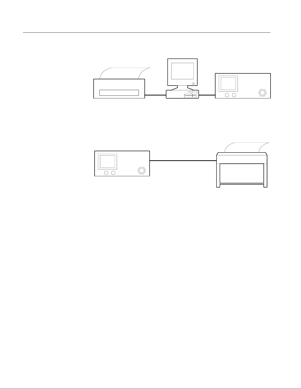
Introduction to Programming
Controller
Hardcopy Device
Spectrum Analyzer
RS-232Centronics
HPGL-Compatible Plotter
or
Epson-Compatible Printer
Spectrum Analyzer
RS-232
Interconnecting Cable
Application Software
Printer or Plotter
(Optional)
Figure 1–1: Two RS-232 System Configurations
An appropriate cable is required to connect between the controller and the
spectrum analyzer. The pinout and connector type on the 2714 or 2715 are
identical to the 9-pin connector used for PC/AT type RS-232 interfaces. Such
cables are available in most computer stores. For some RS-232 devices,
null-modem adapters will be needed. Refer to Appendix A for further information on connectors and adapters.
Application software is the program or programs that control and acquire data
from the spectrum analyzer. You can write your own programs using the
information in this manual. Off-the-shelf software is also available.
A printer or plotter (not both simultaneously) can be connected to the RS-232
interface to provide hard-copy output. A printer is the preferred instrument for
character-based data such as parameter values or instrument settings. Plotters
provide superior results when displaying graphical data.
A printer or plotter cannot be connected to the spectrum analyzer’s interface
when a computer is connected. For this reason you must choose between
computer control or hard-copy output when working directly from the 2714 or
2715’s RS-232 interface. An alternate approach connects the computer to the
1–4
2714 & 2715 Programmer Manual
Page 17

spectrum analyzer interface while using a control program to acquire data from
the spectrum analyzer. A second RS-232 port, a GPIB port, or a Centronics port
on the computer is then used to produce output on a printer or plotter.
Setting Up for RS-232 Operation
Your equipment must be correctly configured before performing RS-232
operations. The following tasks must be completed:
H Installation of cables between the system components
H Configuration of the spectrum analyzer and device driver
H Installation of the device driver into controller memory
H Configuration of the (optional) printer or plotter
This section describes each task in detail.
Introduction to Programming
Connecting the
Equipment
Configuring the
Spectrum Analyzer
Only one device (computer, plotter, or printer) can be attached to the spectrum
analyzer’s RS-232 interface. For systems consisting of a controller and the
spectrum analyzer, simply connect one end of the interconnecting cable to each
device. Figure 1–1 shows two possible configurations. See Appendix A: RS-232
Concepts for the cable configuration appropriate for your system.
Both devices (the computer and spectrum analyzer) in an RS-232 system must be
configured the same way. Before setting up the spectrum analyzer, be sure to
check the configuration settings for the device with which you expect to
communicate.
To set the spectrum analyzer configuration settings, turn on the power to the
2714 or 2715 and press the key sequence
[UTIL] [4] [0] [2]
on the spectrum analyzer KEYPAD. An RS-232 PORT CONFIGURATION
Menu appears that is similar to the one shown in Figure 1–2. This menu allows
for configuration of the spectrum analyzer’s RS-232 parameters. Following are
detailed descriptions of each parameter in the RS-232 PORT CONFIGURATION
Menu.
2714 & 2715 Programmer Manual
1–5
Page 18

Introduction to Programming
RSĆ232 PORT CONFIGURATION
0 STATUS ONLINE/OFFLINE
1 BAUD RATE 110 Ć 9600
2 DATA BITS 7/8
3 PARITY NONE/ODD/EVEN
4 EOL CR/LF/CR LF
5 FLOW CONTROL HARD/SOFT/NONE
6 ECHO ON/OFF
7 VERBOSE ON/OFF
Figure 1–2: The RS-232 Port Configuration Menu
Placing the 2714 or 2715 Online. Item 0 of the RS-232 PORT CONFIGURATION
Menu, STATUS, controls the RS-232 online/offline status. When the status is set
to OFFLINE, the RS-232 interface is ignored; data is neither received nor
transmitted. After all preparations have been completed and RS-232 operations
are ready to begin, press [0] on the KEYPAD to toggle item 0 until the STATUS
indicates ONLINE. The spectrum analyzer is then ready to exchange information
over the RS-232 interface.
Setting the Baud Rate. Item 1 of the RS-232 PORT CONFIGURATION Menu,
BAUD RATE, sets the baud rate of the spectrum analyzer. Baud rate represents
how fast data is transmitted across the interface. To select a baud rate, repeatedly
press [1] on the KEYPAD until the baud rate you desire is displayed. Baud rates
ranging between 110 and 9600 are available.
The number of stop bits used is automatically selected by the spectrum analyzer
when you change baud rates. If the baud rate is 110, two stop bits are selected.
One stop bit is selected for all other baud rates.
NOTE. The spectrum analyzer baud rate must equal the baud rate of the other
device connected to the RS-232 interface.
1–6
2714 & 2715 Programmer Manual
Page 19

Introduction to Programming
Setting the Number of Data Bits. Item 2 of the RS-232 PORT CONFIGURATION
Menu, DATA BITS, selects the number of data bits sent per character. This is
either seven or eight. Eight bits must be selected for binary transfers. Press [2] on
the KEYPAD to choose between seven or eight data bits.
Setting Parity . Item 3 of the RS-232 PORT CONFIGURATION Menu, PARITY,
determines whether odd or even parity is used for data checking, or it selects no
parity checking. The default setting is NONE. To change the PARITY selection,
repeatedly press [3] on the KEYPAD until ODD, EVEN, or NONE is displayed.
Setting the Message Terminator. Item 4 of the RS-232 PORT CONFIGURATION
Menu, EOL, selects the EOL (end-of-line) indicator used to terminate messages
sent over the spectrum analyzer’s RS-232 interface. The terminator can be CR
(carriage return, ASCII 13), LF (line feed, ASCII 10), or CR LF (carriage return
followed by line feed). To change the EOL status selection, repeatedly press [4]
on the KEYPAD until CR, LF, or CRLF is displayed.
When a controller sends data, the spectrum analyzer interprets either CR or LF as
a terminator, independent of the setting.
Selecting a Data Flow Control Method. Item 5 of the RS-232 PORT CONFIGURATION Menu, FLOW CONTROL, selects between three flow control
methods: SOFT, HARD, or NONE. An explanation of each selection follows.
SOFT: When the spectrum analyzer sends data through the interface and SOFT
flow control is enabled, CTRL-S (ASCII 19, same as pressing [CTRL] and [S]
simultaneously) halts the data stream until CTRL-Q (ASCII 17) is received. Any
other character received in the interim is ignored. This type of flow control can
be used with a 3-wire setup because additional handshake lines are not needed.
When SOFT control is selected, the spectrum analyzer sends CTRL-S when its
input data buffer is within 200 characters of being full. It sends CTRL-Q when
the buffer empties to the point at which additional characters can be safely
accepted (less than 200 characters remain in the buffer). If the input buffer is
allowed to overflow, the spectrum analyzer discards the incoming data and
signals an error (Event 372).
HARD: When HARD flow control is selected, the instrument sends data as long
as the CTS (Clear-To-Send) line is TRUE and stops sending data if CTS goes
FALSE. Additional handshake lines (more than a 3-wire RS-232 implementation) are required to support HARD flow control.
When receiving data and HARD flow control is selected, the spectrum analyzer
asserts RTS (Request-To-Send) TRUE until the input buffer is within 200
characters of being full. It then sets RTS FALSE. Data is received while RTS is
FALSE until the buffer overflows. If the buffer is allowed to overflow, the
spectrum analyzer signals an error (Event 372), and incoming data is discarded.
2714 & 2715 Programmer Manual
1–7
Page 20

Introduction to Programming
NONE: No flow control is used.
Follow these general rules when selecting a flow control method:
H Do not use SOFT flow control when transmitting file or waveform data
(binary transfers) because there is no guarantee that the ASCII-decimal
values corresponding to CTRL-S and CTRL-Q do not appear in the input
stream. Instead, specify HARD flow control or NONE for files and
waveform data.
H If NONE is specified, you must ensure that buffers do not overflow. This can
be done by allocating enough buffer space to handle most contingencies. A
buffer size of 1200 is sufficient for most purposes. The 2714 or 2715 uses a
1200-byte, internal input buffer.
Selecting the Echo Feature. Item 6 of the RS-232 PORT CONFIGURATION
Menu, ECHO, chooses ECHO modes of ON or OFF. ECHO mode is intended
primarily as a means of interacting with the 2714 or 2715 from a “dumb”
terminal, or for testing purposes. Press [6] on the KEYPAD to choose between
ON or OFF.
When ECHO is OFF, the spectrum analyzer does not return the characters it
receives to the controller. For most cases, ECHO should be OFF. However, set
ECHO to ON when using a “dumb” terminal to control the spectrum analyzer.
When ECHO is ON, the spectrum analyzer echoes each character it receives back
to the controller. This can cause problems for the control program if it is not
expecting the characters. Additional time is required to process each returned
character, so it is possible to experience buffer overrun at 9600 baud if the
character rate is too high. After each command or query is completed, the
spectrum analyzer prompts for further input by returning the string “>” to the
controller.
For example, if ECHO mode is ON, “>” appears on the terminal or computer
display screen. If the query “VPO?” is entered, the spectrum analyzer returns
“VPO?” followed by a normal response to the query, such as “VPOLARITY
POSITIVE”. It then appends the “>” to indicate that it is ready to receive
additional commands.
ECHO mode is sometimes useful for interactive testing because it lets you see
each character received by the spectrum analyzer. Following are some important
ECHO mode characteristics:
H If SOFT flow control is enabled, CTRL-S and CTRL-Q are not echoed, but
they perform their normal functions.
1–8
H If either CR or LF is received by the spectrum analyzer, it is echoed as the
currently selected output terminator.
2714 & 2715 Programmer Manual
Page 21

Introduction to Programming
H Any other control character echoes as an up arrow (^) followed by a capital
letter. For example, ^X represents pressing the [CTRL] and [X] keys at the
same time.
H ECHO should not be ON with binary transfers.
H When ECHO is ON the prompt character appears on the display under other
conditions: 1) when the instrument is powered up or placed on-line with
ECHO mode ON, 2) when ECHO is turned on, and 3) after a device clear
(break) is received.
Verbose Mode and Error Handling. Item 7 of the RS-232 PORT CONFIGURATION Menu, VERBOSE, turns VERBOSE mode ON and OFF. This feature
is provided as an alternative to the GPIB SRQ mechanism. It is generally used
when controlling the spectrum analyzer with a “dumb” terminal. Press [7] on the
KEYPAD to choose between ON or OFF.
When ON, VERBOSE mode forces the spectrum analyzer to respond for each
command it receives. The response will be one of the following:
Installing and Configuring
the Device Driver
H An event code for an abnormal condition
H A response for a successful query (FREq?)
H The string “OK” for a successful non-query
Refer to Status Reporting for additional information on error handling for
instruments with the RS-232 interface.
If you are using special applications software or a custom RS-232 driver, follow
the detailed instructions for installing and configuring the device driver included
with it. However, for PC-type controllers running MS-DOS, the driver is part of
the operating system. You can configure a serial communications port with the
MODE command by entering a command similar to the following example:
MODE COM1:9600,n,8,1
This command configures the COM1 interface to run at 9600 baud, no parity, 8
data bits, and 1 stop bit.
NOTE. You must use the same setup information for the controller and the
spectrum analyzer.
A program statement, such as OPEN in the BASIC language, is an alternative way
to configure the driver. This method of driver configuration is recommended
because it sets the driver to a known, and presumably correct, operating state
from within the application program and just prior to actual operation. If the
2714 & 2715 Programmer Manual
1–9
Page 22

Introduction to Programming
MODE command is used, the last settings applied to the interface must be used. If
this data is not used, your program will not work properly.
Configuring the (Optional)
Printer or Plotter
Communicating with the
Spectrum Analyzer
A variety of printers and plotters are available for use with your system. The
serial or parallel printer of your choice may be connected to the appropriate
computer port. For example, the Centronics- or GPIB-compatible, 4-pen
Tektronix HC100 plotter is recommended. Its four pens provide a useful
complement to the four-trace capability of the 2714 or 2715.
A serial printer or plotter, such as the Tektronix HC100 Option 03, can be
attached to the spectrum analyzer’s RS-232 interface instead of a computer
controller. This arrangement enables data transfer directly from the spectrum
analyzer to the printer or plotter with a remote PLOT command when the system
controller is unavailable. Of course, the spectrum analyzer must be correctly
configured using the SCREEN PLOT CONFIGURATION Menu (key sequence
[UTIL] [4] [1]).
Figure 1–1, located earlier in this section, shows two alternative configurations
using a printer. A plotter could be substituted for the printer in either configuration.
The RS-232 interface enables remote or automated control of the 2714 or 2715
Spectrum Analyzer. An application program (often called a test, measurement, or
control program) determines 2714 or 2715 operations by exchanging spectrum
analyzer-specific messages with the instrument.
Preparing the Software
The spectrum analyzer-specific messages are also referred to as device-dependent
messages. They are generally understood by and meaningful to only the
instrument, or class of instruments, for which they are designed. The organization of the spectrum analyzer-specific messages is explained in the next section
of this manual. Functional Groups provides a summary of the messages.
Command and Query Definitions describes the individual messages in detail, and
Programming provides some programming examples.
Programmed commands and data are transmitted over the interface to the
instrument as soon as they are delivered to the driver. If the command is a query
(FREQ? for example), the spectrum analyzer formats a response immediately and
sends it back to the computer. The control program is responsible for handling
incoming data in a timely fashion.
After completing the setup procedures your equipment is ready for RS-232
operation, but you must still provide the software needed to control the spectrum
analyzer. When creating new software this is usually a two step process. The first
step is to establish the programming environment. Next you can create and run
the control program. If you are using ready-made control software, simply follow
the supplier’s instructions.
1–10
2714 & 2715 Programmer Manual
Page 23

The programming requirements for RS-232 control are more complex than those
for GPIB operation. Programming contains a complete example of an interactive
RS-232 control program. This program is functionally similar to the GPIB
program example located later in this section (refer to A GPIB Instrument
Control Program on page 1–23).
GPIB Operation (Option 03)
Option 03 adds a General Purpose Interface Bus (GPIB) port. This GPIB port
conforms to the IEEE 488.1 Standard and to the Tektronix Interface Standard for
GPIB Codes, Formats, Conventions, and Features. This standard promotes ease
of operation and, so far as possible, makes this spectrum analyzer compatible
with other Tektronix instruments and with GPIB instruments from other
manufacturers.
The IEEE 488.1 Standard establishes electrical levels, connector configuration,
and signal protocols for communication between two or more electronic
instruments using a common multi-line bus structure. The bus structure, known
as the GPIB, consists of eight data lines, eight dedicated control signal lines, a
shield, and various grounds.
Introduction to Programming
Data is transferred via eight data lines in a bit parallel, byte serial fashion. That
is, the eight bits of a data byte are placed on the eight data lines simultaneously.
As soon as they are transferred, the next 8-bit data byte is placed on the lines and
is transferred. Data consists of instrument commands and queries, control
settings, parameter values, or display information.
The eight control lines are divided into three transfer control (handshake) lines
and five interface management lines. Handshaking and interface management are
necessary because the bus operates asynchronously. This means that signals can
be generated by one instrument without regard for what other instruments may
be doing, or the rate at which other instruments can carry out an operation. For
instance, two instruments may try to send information simultaneously, or a high
speed instrument may try to send data to a slower instrument.
Instruments connected to the bus are designated as talker, listener, or both talker
and listener. A listener can only receive information over the bus and a talker can
only send information. A talker and listener can do both (but not simultaneously).
One instrument is usually designated as the system controller. This is generally a
computer that determines, through software, when specific instruments are
activated as talkers or listeners. Each instrument is assigned a unique address
between 0 and 30, but only 15 instruments can be connected to the bus
simultaneously.
2714 & 2715 Programmer Manual
1–11
Page 24

Introduction to Programming
The following example illustrates how data transfer typically takes place (except
in the case of abnormal events; see Status Reporting).
1. The instrument on the bus that is designated as system controller determines
(through operator intervention or program control) that it needs to send a
message to one of the other instruments.
2. Using the data and interface management lines, the controller first addresses
the desired instrument as a listener. This is called LISTENING an instrument.
3. Instruments on the bus are normally idle, and they signal using the hand-
shake lines when they are ready to receive data. The controller then places
the first byte of the message on the bus, indicating the type of information it
wants.
4. Next the controller signals, using the handshake lines, that the data byte is
ready.
5. As the listener accepts the data byte, it signals over the handshake lines that
it has done so. The controller then removes the data from the data lines.
6. The process from steps 3, 4, and 5 is repeated until the entire message has
been transferred.
7. The controller indicates that the last data byte has been sent. Depending on
the option selected, one of two methods is used: 1) Signaling over the end or
identify (EOI) interface management line simultaneously with the last data
byte, or 2) Appending the ASCII codes for carriage return (CR) and line feed
(LF) to the end of the message and simultaneously signaling EOI.
8. When the message is complete, the controller normally UNLISTENS the
instrument. If a message requires a response, the controller then addresses
the instrument as a talker (TALKS the instrument).
9. Now the instrument places the first byte of the response on the data bus and
signals that it is ready.
10. After the controller reads the byte, it signals (over the handshake lines) that it
has done so and is ready to receive more data. The process repeats until EOI
is detected, at which point the controller normally UNTALKS the instrument.
The data transfer process is transparent to you. It is carried out by the spectrum
analyzer, the GPIB board in your controller, and the device driver software
(generally supplied with the GPIB board). In the following subsections you will
learn how to set up your spectrum analyzer for GPIB operation. See Appendix B:
GPIB System Concepts for additional information concerning IEEE 488.1 and
the GPIB.
1–12
2714 & 2715 Programmer Manual
Page 25

Operation Over the GPIB
The following equipment is required to operate the 2714 or 2715 Spectrum
Analyzer over the General Purpose Interface Bus (GPIB):
H System controller
H Software device driver
H 2714 or 2715 equipped with the GPIB interface (Option 03)
H Interconnecting cable
H Application software
H Printer or plotter (optional)
Figure 1–3 shows an example of a simple GPIB system consisting of a printer
and plotter.
Introduction to Programming
System Controller
Software Device Driver
The system controller can be any general purpose computer equipped with a
GPIB board. Specially built controllers can also be used, but are beyond the
scope of this manual. The techniques and programs discussed in this manual are
appropriate to the IBM family of personal computers (PCs) and their functionalike counterparts, which support the MS-DOS, PC-DOS, or OS/2 environments.
To function as a controller, your computer must be equipped with a GPIB board.
Tektronix supplies three National Instruments GPIB boards for your convenience:
H PC-GPIB Package provides a PCII/IIA board; order S3FG210
H AT-GPIB Package provides a 16-bit AT Bus interface board; order S3FG220
H MC-GPIB Package provides a 16-bit Micro Channel interface board; order
S3FG230
The device driver is a program (usually supplied with the GPIB board) that tells
your computer how to access the board. For the National Instruments PCII,
PCIIA, or PCII/IIA GPIB boards, the device driver is a file named GPIB.COM. An
additional program is usually supplied that enables you to correctly configure the
driver by providing information such as the instrument address and the type of
message terminator. The National Instruments program is named IBCONF.EXE.
2714 & 2715 Programmer Manual
1–13
Page 26

Introduction to Programming
Controller
Hardcopy Device
Spectrum Analyzer
RS-232Centronics
Plotter
GPIB
2714 or 2715 Equipped
with the GPIB Interface
(Option 03)
Interconnect Cable
Application Software
Figure 1–3: T ypical Small Instrument System for GPIB
Your 2714 or 2715 must be equipped with the Option 03 GPIB interface to
operate over the General Purpose Interface Bus. Refer to RS-232 Operation
(Option 08) on page 1–1 for configuration information if your instrument has
the RS-232 interface. Press the key sequence [UTIL] [4] [9] to see a list of the
installed options and capabilities.
An appropriate interconnect cable is required to connect the controller to the
spectrum analyzer. Cables may be purchased from Tektronix by ordering one of
these part numbers:
H P/N 012-0991-01 (1 meter)
H P/N 012-0630-01 (2 meter)
Application software is the program or programs that control and acquire data
from the spectrum analyzer. You can write your own programs with the
information in this manual. However, you will need the applications interface
software supplied by the GPIB board manufacturer. For the PCII/IIA board and
the QuickBASIC language, these programs have names such as QBIB4.OBJ,
QBIB4728.OBJ, and QBDECL4.BAS. The programs include the BASIC device
function calls which enable you to communicate easily over the GPIB. The
function calls are an integral part of your application programs.
1–14
2714 & 2715 Programmer Manual
Page 27

Introduction to Programming
Printer or Plotter
(Optional)
A printer, a plotter, or both can be added to your system to provide hard-copy
output. Printers are preferred for character-based data such as parameter values or
instrument settings. Plotters provide superior results when displaying graphical
data. A convenient approach is to install a printer on a parallel port of the
controller and a GPIB-compatible plotter on the bus. With this approach,
graphical data can be plotted directly from the spectrum analyzer when the
controller is not available.
See Setting the TALK ONLY Option on page 1–18.
Setting Up for GPIB Operation
Your equipment must be correctly configured before GPIB operations can be
performed. The following tasks must be completed:
H Installation of cables between the system components
H Configuration of the spectrum analyzer and device driver
H Installation of the device driver into controller memory
H Configuration of the (optional) printer and/or plotter
This section describes each task in detail.
Connecting the
Equipment
Configuring the Spectrum
Analyzer
Placing the 2714 or 2715
Online
If your system consists of a controller and spectrum analyzer, you can simply
connect one end of the interconnecting cable to each instrument. A star configuration, daisy chain configuration, or combination of these (Figure 1–4) should be
used when more than two instruments are on the bus. Up to 15 instruments can
be connected.
To maintain electrical performance of the bus, use only one 2-meter cable per
instrument, and ensure that at least 2/3 of the connected instruments are
powered up.
Turn on the power to the spectrum analyzer. Press the key sequence:
[UTIL] [4] [0] [0]
A GPIB PORT CONFIGURATION Menu appears. It should resemble the one
shown in Figure 1–5. You will use this menu to configure the GPIB parameters.
Item 0 of the GPIB PORT CONFIGURATION Menu, STATUS, controls the
GPIB ONLINE/OFFLINE status (see Figure 1–5). After all preparations have
been completed and GPIB operations are ready to begin, press [0] on the
KEYPAD to toggle item 0 until the STATUS indicates ONLINE. The spectrum
analyzer is then ready to exchange information over the GPIB.
2714 & 2715 Programmer Manual
1–15
Page 28

Introduction to Programming
C
B D
A
Setting the GPIB Device
Address
F
A B C D E F
Star
Daisy Chain
E
Figure 1–4: Connecting Multiple Instruments on the GPIB
Item 1 of the GPIB PORT CONFIGURATION Menu, GPIB ADDRESS, sets the
spectrum analyzer’s GPIB device address. You must assign a primary address to
the spectrum analyzer (the 2714 or 2715 does not support secondary addresses).
The address can have a value from 0 through 30. However, addresses 0 and 30
are usually reserved for system controllers.
1–16
2714 & 2715 Programmer Manual
Page 29

Introduction to Programming
GPIB PORT CONFIGURATION
0 STATUS ON/OFFLINE
1 GPIB ADDRESS 0 Ć 30
2 POWER ON SRQ ON/OFF
3 EOI/LF MODE LF/EOI
4 TALK ONLY MODE ON/OFF
Figure 1–5: The Spectrum Analyzer’s GPIB PORT CONFIGURATION Menu
The Power-On SRQ
The address you assign is not critical, but it must not be the same address used
for any other instrument on the bus.
NOTE. The GPIB address assigned to the spectrum analyzer must be the same as
the one that was used to configure the device driver for the spectrum analyzer.
To assign the address, select item 1, GPIB ADDRESS, from the GPIB PORT
CONFIGURATION Menu. Follow the on-screen prompts to enter the desired
address using the KEYPAD for data entry. If the spectrum analyzer is the only
instrument on the bus, we suggest using 1 as the address. The address you set is
read immediately by the spectrum analyzer and is permanently retained in
non-volatile memory.
Item 2 of the GPIB PORT CONFIGURATION Menu, POWER ON SRQ, causes
the spectrum analyzer to produce an SRQ at power up. To generate a POWER
ON SRQ, press [2] on the KEYPAD until the status changes to ON.
Normally there is no need to have the spectrum analyzer generate an SRQ when
it powers up. Therefore, the default setting of item 2, POWER ON SRQ, is OFF.
However, some test sequences require that the power to the spectrum analyzer is
removed (power down). Under these conditions it may be beneficial for the
program to sense the return of power.
2714 & 2715 Programmer Manual
1–17
Page 30

Introduction to Programming
Setting the Message
Terminator
Setting the TALK ONLY
Option
Item 3 of the GPIB PORT CONFIGURATION Menu, EOI/LF MODE, selects
the message terminator. Whenever a message is transmitted over the bus, the
instrument sending the message must signify to other instruments on the bus
(including the system controller) that the message has been completed. This is
done in one of two ways:
H The interface management line named End Or Identify (EOI) is brought to
its low state simultaneously with the last data byte that is transmitted.
H The ASCII codes for carriage return (CR) and line feed (LF) are appended to
the message string. EOI is still asserted (brought to its low state) simultaneously with the transmission of LF.
All Tektronix instruments and controllers are equipped to use the EOI selection.
You should, therefore, toggle item 3 of the GPIB PORT CONFIGURATION
Menu until its status changes to EOI. The LF OR EOI setting is included for
controllers that do not use the EOI signal line. The selection you choose is
permanently retained in non-volatile memory.
Item 4 of the GPIB PORT CONFIGURATION Menu, TALK ONLY MODE,
selects the spectrum analyzer’s TALK ONLY mode.
TALK ONLY mode must be selected to send the spectrum analyzer’s output
directly to a plotter without the use of a controller. Complete these steps to send
the spectrum analyzer’s display directly to a plotter:
Configuring the Device
Driver
1. Disconnect all instruments except the spectrum analyzer and the plotter from
the bus.
2. Place the plotter in the LISTEN ONLY mode (usually done with controls on
the plotter).
3. Press the key sequence [UTIL] [4] [0] and then press [4] until the TALK
ONLY status indicates ON.
4. Press the front-panel key labelled [PLOT].
TALK ONLY mode must be disabled when the spectrum analyzer is used with a
controller, because the spectrum analyzer must talk to and listen to the controller.
To use the spectrum analyzer with a controller, press [4] on the KEYPAD until
the status indicates OFF. The system controller will determine when the
spectrum analyzer should be addressed as a talker or listener.
Instructions for configuring the device driver should be included with your GPIB
board. For example, complete the following steps when using a National
Instruments PCII/IIA board:
1. Run the IBCONF.EXE program to configure the driver.
1–18
2714 & 2715 Programmer Manual
Page 31

Introduction to Programming
2. Follow the on-screen prompts and ensure that the BOARD CHARACTER-
ISTICS screen resembles one of those shown in Table 1–1 and 1–2.
3. Create or edit the DEVICE CHARACTERISTICS screen for a device named
TEK_SA (see Table 1–3).
NOTE. You must assign the same GPIB address to the spectrum analyzer that
was used when configuring the device driver for the spectrum analyzer. Use the
EOI message terminator for all Tektronix controllers.
T able 1–1: National Instruments PCII Board Characteristics
Primary GPIB address 0
Secondary GPIB address NONE
Timeout setting T30s
EOS byte 00H
Terminate Read on EOS no
Set EOI with EOS on Write no
Type of compare on EOS 7-bit
Set EOI with last byte of Write yes
GPIB-PC model PC2
Board is system controller yes
Local lockout on all devices no
Disable auto serial polling yes
High-speed timing no
Interrupt jumper setting 7
Base I/O address 2B8H
DMA channel 1
Internal clock freq (in MHz) 8
T able 1–2: National Instruments PCIIA Board Characteristics
Primary GPIB address 0
2714 & 2715 Programmer Manual
Secondary GPIB address NONE
Timeout setting T30s
EOS byte 00H
Terminate Read on EOS no
1–19
Page 32

Introduction to Programming
T able 1–2: National Instruments PCIIA Board Characteristics (Cont.)
Set EOI with EOS on Write no
Type of compare on EOS 7-bit
Set EOI with last byte of Write yes
GPIB-PC model PC2A
Board is system controller yes
Local lockout on all devices no
Disable auto serial polling yes
High-speed timing no
Interrupt jumper setting 7
Base I/O address 02E1H
DMA channel 1
Internal clock freq (in MHz) 6
Installing the Device
Driver
T able 1–3: TEK_SA Device Characteristics
Primary GPIB address 1
Secondary GPIB address NONE
Timeout setting T30s
EOS byte 00H
Terminate Read on EOS no
Set EOI with EOS on Write no
Before your computer can transfer information over the GPIB, it must know how
to access the GPIB board and the spectrum analyzer. The device driver tells it
how. If you are using a National Instruments PCII/IIA board, the device driver is
a program named GPIB.COM created and modified by another National Instruments program named IBCONF.EXE. If you are using a board from another
manufacturer, the appropriate driver should have accompanied your board.
The device driver program must be installed whenever you wish to use the
GPIB. Use the following procedure. Refer to your DOS manual if you need help
creating or modifying files.
1. Copy GPIB.COM to your computer’s root directory.
1–20
2. Add the following line to your CONFIG.SYS file:
device=GPIB.COM
2714 & 2715 Programmer Manual
Page 33

Introduction to Programming
OFF
1
3. If CONFIG.SYS does not already exist in the controller’s root directory, create
a new CONFIG.SYS file.
4. Reboot your controller.
The GPIB device driver is loaded into memory whenever you boot your
computer. It then remains in memory until the computer is turned off or until a
reboot is performed.
Configuring the (Optional)
Printer or Plotter
A variety of printers and plotters are available that can be used with your system.
We recommend a serial or parallel printer connected to the appropriate computer
port, and/or an HPGL-compatible plotter connected to the GPIB. This arrangement allows data to be sent directly from the spectrum analyzer to the plotter
when the system controller is unavailable. The Tektronix HC100 plotter is
recommended. Its four pens provide a useful complement to the four-trace
capability of the 2714 or 2715.
Printer Configuration. Configuration of the printer is independent of the GPIB.
Consult your printer and computer manuals for information on setting up the
printer and corresponding computer communications port.
Plotter Configuration. Plotter configuration procedures vary. Consult your plotter
manual for the configuration appropriate to your plotter.
When using a Tektronix HC100 plotter, set its rear-panel DIP switches as
follows:
16 8 4 2 1
ON GPIB HPGL STD
Down Down Down Up Up Up Up Up
Address (Listen Only = 31)
0
All bits should be set when the Tektronix HC100 plotter is in LISTEN ONLY
mode, and its power must be cycled to load the settings into memory. You must
also correctly configure the plotter DEVICE CHARACTERISTICS using the
IBCONF file.
NOTE. Be sure to use the same GPIB address for the HC100 DIP switches and
the DEVICE CHARACTERISTICS.
2714 & 2715 Programmer Manual
1–21
Page 34

Introduction to Programming
Communicating with
the 2714 or 2715
The GPIB enables remote or automated control of instruments on the bus (in this
case, a spectrum analyzer). An application program (often called a test, measurement, or control program) determines spectrum analyzer operations by exchanging messages with the spectrum analyzer. The messages can be of the generic
GPIB type, or they can be instrument-specific.
Generic messages are usually carried out by GPIB hardware and the GPIB device
driver without intervention by the operator or programmer. They typically
implement routine housekeeping chores such as instrument addressing,
handshaking, requesting service, or terminating messages.
The instrument-specific messages are also referred to as device-dependent
messages. They are generally understood by, and meaningful to, only the
instrument or class of instruments for which they are designed. The organization
of the instrument-specific messages is explained in the next section of this
manual. Functional Groups provides a summary of the messages. Command and
Query Definitions describes the individual messages in detail, and Programming
provides some programming examples for the National Instruments GPIB/2714
or 2715 combination working in the QuickBASIC environment.
The spectrum analyzer is addressed as a talker or listener to send or receive
messages, depending on whether messages are being sent to or received from the
system controller. The GPIB system software provided with your GPIB card
automatically addresses the spectrum analyzer as a talker or listener depending
on the callable subroutine used. The device-dependent messages are then
transferred between the controller and the spectrum analyzer over the GPIB as
one or more eight-bit bytes of information. Proficiency in controlling the
spectrum analyzer is the key to programming these messages efficiently.
Preparing the Software
1–22
After completing the setup procedures your equipment is ready for GPIB
operation, but you must still provide the software needed to control the spectrum
analyzer. When creating new software this is usually a two step process. The first
step is to establish the programming environment. Next you can create and run
the control program. If you are using ready-made control software, simply follow
the supplier’s instructions.
When creating your own QuickBASIC software, you must ensure that QuickBASIC has the necessary GPIB information. Use the following procedure. Refer
to your DOS manual if you need help creating or modifying files.
H Copy the files QBIB4.OBJ, GPIB.QLB, GPIB.LIB, BQLB45.LIB, and
QBIB4728.OBJ from the National Instrument’s disk to the QuickBASIC
directory.
H Create the Quick library by typing this command from the DOS command
line:
LINK /Q QBIB4.OBJ QBIB4728.OBJ,GPIB.QLB,,BQLB45.LIB
2714 & 2715 Programmer Manual
Page 35

Introduction to Programming
H To make your QuickBASIC program a stand-alone *.EXE file, you need an
additional library file. Type this command from the DOS command line:
LIB GPIB.LIB + QBIB4.OBJ + QBIB4728.OBJ;
H Start QuickBASIC using this command:
QB /L GPIB.QLB
This procedure ensures that the National Instruments GPIB subroutines needed
to control devices on the bus are present in the QuickBASIC environment. When
using another version of QuickBASIC, use the analogous files and procedures
indicated in the READĆQB.DOC document file from National Instruments.
A GPIB Instrument
Control Program
You will learn more about controlling the spectrum analyzer in Sections 4
through 6 in this manual. However, we have provided a simple program here so
you can check the operation of your system and observe typical interactions
between the controller and spectrum analyzer. Be aware that the program is very
basic; it contains no error checking and may hang up the controller (requiring
you to reboot) if incorrect or unacceptable commands or queries are entered. It
will, however, accept uppercase or lowercase entries.
Alternatively, you can use the IBIC program supplied with the National
Instruments PCII/IIA GPIB board. It enables you to communicate with the
spectrum analyzer, but requires that you learn how to use a few simple subroutines such as IBWRT() and IBRD(). See your National Instruments documentation for details.
Follow these steps to use the Example Program 1-1 located on the following
pages (REM $INCLUDE: 'QBDECL4.BAS').
1. Start QuickBASIC according to the instructions in Installing and Configur-
ing the Device Driver on page 1–9. Enter the program. Be sure to enter the
program exactly as it is written. The spectrum analyzer must be named
TEK_SA by the IBCONF program.
2. Place the spectrum analyzer ONLINE by selecting item 0 from the GPIB
PORT CONFIGURATION Menu (press the key sequence [UTIL] [4] [0]
[0]). The instrument is nominally ONLINE, but is not yet handshaking with
the controller.
3. Start the program. The computer display shows:
2714 & 2715 Programmer Manual
2714 or 2715 SHOULD NOW BE HANDSHAKING
NDAC SHOULD BE DISPLAYED
PRESS ANY KEY TO CONTINUE
When the spectrum analyzer is handshaking with the controller, NDAC (Not
Data ACcepted) is displayed at the lower right of the spectrum analyzer’s
screen. NDAC is asserted most of the time. It is unasserted only briefly
1–23
Page 36

Introduction to Programming
following receipt of a message to indicate that the message has been
accepted (see Appendix B: GPIB System Concepts).
4. Press any key. The word REMOTE should appear at the lower left of the
spectrum analyzer’s screen and the controller should display these messages:
2714 or 2715 SHOULD NOW BE IN REMOTE MODE
PRESS ANY KEY TO CONTINUE
The National Instruments software places the spectrum analyzer in remote
mode whenever a message is sent (the message HDR ON was transmitted).
Unless the GPIB local lockout command is issued, any spectrum analyzer
key which alters its measurement status may be pressed to return the
spectrum analyzer to local mode. (For example, the [MENU] keys do not
change the status, but items selected from a menu may change the status.)
5. Press the [VID FLTR] key twice. The REMOTE message should disappear
from the spectrum analyzer screen.
6. Press any key. This message should appear:
ENTER MESSAGE TO SEND
Enter the message you want to send, which can be either a command or
query. For example, enter this query requesting the spectrum analyzer to
identify itself:
ID?
7. REMOTE should reappear on the spectrum analyzer screen. The word TALKER
or LISTENER will also appear momentarily. These words are displayed when
the spectrum analyzer enters the indicated mode, but because of timing
considerations, they do not always appear for short commands, queries, and
responses. You should see a response similar to the following one on the
controller’s screen:
ID TEK/2714 or 2715,V81.1,"VERSION 02.28.92 FIRMWARE",
"GPIB", "NVM 12.88", "OPT NVM 12.88";
8. The actual response depends on the options in your instrument.
9. You will then be asked:
SEND MORE (Y/N)?
Enter “Y” to send more; other answers end the program.
1–24
2714 & 2715 Programmer Manual
Page 37

Introduction to Programming
NOTE. The 2714 or 2715 must have a spectral display on its screen when any
RS-232 or GPIB program is executed. If the 2714 or 2715 is displaying a menu
when a program is executed, the program will not run properly.
Example: GPIB Test
Program
REM $INCLUDE: 'QBDECL4.BAS'
RD$ = SPACE$(3000)
CLS
CALL IBFIND("GPIB0", BD%)
V%=0
CALL IBSRE(BD%, V%)
CALL IBFIND("TEK_SA", BD%)
PRINT "2714 or 2715 SHOULD NOW BE HANDSHAKING"
PRINT "NDAC SHOULD BE DISPLAYED"
PRINT:PRINT "PRESS ANY KEY TO CONTINUE"
DO WHILE INKEY$ = ""
LOOP
WRT$ = "HDR ON"
CALL IBWRT(BD%, WRT$)
PRINT "2714 or 2715 SHOULD NOW BE IN REMOTE MODE"
PRINT:PRINT "PRESS ANY KEY TO CONTINUE"
DO WHILE INKEY$ = ""
LOOP
SEND.RCV:
CLS
PRINT:PRINT "ENTER MESSAGE TO SEND"
PRINT : INPUT WCALL IBWRT(BD%, WRT$)
QUES = INSTR(1, WRT$, "?")
HOLD.TIME = TIMER
DO WHILE TIMER < HOLD.TIME + 1
LOOP
IF QUES = 0 THEN GOTO MORE
CALL IBRD(BD%, RD$)
PRINT:PRINT "THE REPLY IS:"
PRINT:PRINT MID$(RD$, 1, IBCNT%)
MORE:
PRINT:PRINT
INPUT "SEND MORE (Y/N)? "; Y$
IF Y$ = "Y" THEN GOTO SEND.RCV
END
2714 & 2715 Programmer Manual
1–25
Page 38

Introduction to Programming
1–26
2714 & 2715 Programmer Manual
Page 39

Message Structure
Page 40

Page 41

Instrument-Specific Message Structure
Communications between the system controller and the 2714 or 2715 are
accomplished by instrument-specific messages. Instrument-specific messages
exchanged over the RS-232 or GPIB interface control the measurement and
display functions of the spectrum analyzer. These messages are always transmitted over the data lines (with the exception of the EOI message terminator).
Instrument-specific messages control parameters such as center frequency,
span/division, reference level, and resolution bandwidth. It is the system
programmer’s task to efficiently compile a series of messages in a script
designed to implement specific tests and measurements. The script, or control
program, is written in a conventional computer language and embodies specific
spectrum analyzer commands and queries.
When the GPIB interface is installed, generic GPIB messages are exchanged
between the system controller and the 2714 or 2715 in addition to instrumentspecific messages. Generic GPIB messages exercise control over the bus and
carry out routine system operations such as instrument addressing, handshaking,
requesting service, and terminating messages. GPIB messages may be transmitted over the handshake lines or interface management lines (uni-line
messages), or they may be transmitted over the data lines (multi-line messages).
The GPIB hardware and software usually sends and receives these messages in a
way that is transparent to the system operator or programmer. Refer to
Appendix B: GPIB System Concepts for additional information about uni- and
multi-line messages.
What Is A Message?
An instrument-specific message consists of three or more 8-bit bytes of
information that are transferred between the spectrum analyzer and the system
controller. Each byte represents an ASCII character or binary data. A message
may be an input message or an output message. It may contain one or more
message units.
For instance, here is an example of a message from Mary to John:
2714 & 2715 Programmer Manual
John
dinner Ć put in oven; washing machine Ć start; bank Ć
withdraw how much?; cat Ć let her in
Bye bye
2–1
Page 42

Instrument-Specific Message Structure
John’s response may resemble this one:
Mary
$100
Bye bye
He could also respond this way:
Mary
Withdraw Ć $100
Bye bye
These messages are structured in a similar manner. Each contains a salutation
(John and Mary). Each message consists of one or more message units. For
instance, Mary’s message to John has four units. One of these is a query and is
identified by a question mark (?). Each message unit begins with a “header”
describing what the message is about (such as dinner or cat). The header is
separated from its object or argument by a dash (–), which is the argument
delimiter. Message units are separated or delimited by semicolons (;).
Message Unit
Input Message
Output Message
Each of John’s messages to Mary consist of a single response indicating how
much money she should withdraw. If John thinks Mary will remember her own
question (withdraw how much?), he may simply reply “$100” as in the first
example. However, to relate his response to her question he may answer
“Withdraw - $100” as in the second example. The latter form is equivalent to
receiving a response from the spectrum analyzer when HDR ON is selected (see
Command and Query Definitions). Both messages close with a message
terminator “Bye bye”.
The instrument-specific messages for the 2714 or 2715 are constructed in a
similar way. The following definitions clarify the structure.
A message unit is a single command, query, or response.
An input message is one or more message units, along with any message unit
delimiters (separators) and a message terminator, transmitted from the controller
to the 2714 or 2715.
An output message is one or more message units, along with any message unit
delimiters (separators) and a message terminator, transmitted from the 2714 or
2715 to the controller.
2–2
2714 & 2715 Programmer Manual
Page 43

Instrument-Specific Message Structure
Message Unit Delimiter
Message Terminator
(RS-232)
A semicolon (;) must be used to delimit or separate message units in a message.
Following the last message unit, the use of a delimiter is optional with one
exception. The 2714 or 2715 always appends a message unit delimiter as the last
data byte when it sends a response.
If desired, you may substitute the line feed character for the semicolon in the
case of responses (see the MSGdlm command in Command and Query Defini-
tions). Do not confuse the line feed character with the optional message
terminator discussed next.
When a controller sends data to the 2714 or 2715, the spectrum analyzer
interprets both CR and LF as message terminators. Messages sent by the
spectrum analyzer over the RS-232 interface can be terminated in the following
ways:
H By CR only (carriage return, ASCII 13)
H By LF only (line feed, ASCII 10)
H By CR-LF (carriage return followed by line feed)
See Setting the Message Terminator in the Setting Up for RS-232 Operation part
of Introduction to Programming for instructions about configuring the message
terminator for RS-232 instruments.
Message Terminator
(GPIB)
Command
Messages exchanged over the GPIB interface (Option 03) can be terminated in
one of two ways:
H The EOI interface management line is brought low (asserted) simultaneously
with the last byte of the message.
H ASCII codes for carriage return (CR) and line feed (LF) are appended to the
end of message, and the EOI interface management line is asserted simultaneously with transmission of the LF character.
All Tektronix instruments assert the EOI line. The CR-LF terminator option is
provided for instruments that do not use the EOI line. If you are using such an
instrument, select the CR-LF option (see Setting the Message Terminator in the
Setting Up for GPIB Operation part of Introduction to Programming). Termina-
tor control is handled automatically by the GPIB hardware and software.
A command generally consists of a command mnemonic or header, header
delimiter, argument(s), and argument delimiter. For example, the command
SAVE A:ON, B:ON
enables the SAVE A and SAVE B functions. In this example, SAVE is the
command header. The space between SAVE and A:ON is the header delimiter.
2714 & 2715 Programmer Manual
2–3
Page 44

Instrument-Specific Message Structure
A:ON and B:ON are arguments, and the comma (,) following A:ON is the argument
delimiter.
Some commands have no arguments, or only one argument, and may not require
header or argument delimiters. For instance, the command
GTL
returns the 2714 or 2715 to local control without adding arguments or delimiters.
Query
Response
A query consists of a query mnemonic or header, a question mark (?), header
delimiter, and an argument. Many queries do not require an argument.
For example, the query
CURve?
may be used with arguments A, B, C, or D to determine the contents of a display
register. The query
CFSF?
simply returns a response that indicates whether the on-screen frequency is
Center Frequency or Start Frequency.
A response is information returned as the result of a query. It consists of an
optional response mnemonic or header, header delimiter, argument(s), and
argument delimiter. For example,
CFSF CENTER
CFSF START
are the possible responses to the CFSF? query.
Mnemonic or Header
Header Delimiter
2–4
Digit
A header is a short name associated with each command, query, or response (for
example, FREq, REF, MAR). Whenever possible, headers are mnemonic in nature
so the name indicates the function.
A header delimiter is a blank space. Command headers, response headers, and
the question mark (?) following a query header are delimited or separated from
any following arguments by a space. The space is optional if there are no
arguments.
Digits are any of these numbers: 0, 1, 2, 3, 4, 5, 6, 7, 8, or 9.
2714 & 2715 Programmer Manual
Page 45

Instrument-Specific Message Structure
Units
Units specify the unit of measure. Except in the case of decibels (dBs), only the
first letter of the units is used. Message context determines how the first letter is
interpreted. For instance, the command
FREq 10 M
is the same as
FREq 10 MHZ
For either command the M is interpreted as MHz because frequency corresponds
to the FREq command. In a similar manner, the letter M would indicate milliseconds when used within the TIMe 10 M command.
Engineering units can be appended to certain number arguments (FREq 10E+6 is
the same as FREq 10 MHZ).
Commands such as REFlvl require the entire dB unit (dBmV, dBm, etc.) to
avoid confusion. You can place as many spaces as desired between the number
and its units.
Responses with numerical arguments DO NOT append units to the argument.
The programmer must keep track of the units, or use a query that responds with
the units currently in use (for instance, the RLUnit? query).
Argument
Number Argument
Character Argument
An argument is the value that a command, query, or response transfers to or from
its associated 2714 or 2715 setting(s). For instance, from the command
FREq 200 MHZ
the value of 200 MHz is transferred to the center frequency setting. Arguments
may be numbers (with or without units), characters, strings, or linked with a
colon (:). A block of binary data may comprise the argument of some waveform
commands and responses.
Number refers to a decimal number consisting of one or more digits. Three
number formats are possible:
nr1 Integer (no decimal point)
nr2 Floating point number (decimal point required)
nr3 Integer or floating point number in scientific notation
(2.0E+3 or 2.000E+3, for example, instead of 2000)
A character argument consists of one or more letters usually expressing a word
or mnemonic. For instance, ON and OFF are arguments for commands that control
2714 or 2715 functions such as AREs (auto resolution bandwidth).
2714 & 2715 Programmer Manual
2–5
Page 46

Instrument-Specific Message Structure
String Argument
Link Argument
Binary Block Argument
String arguments consist of one or more characters, including spaces, enclosed in
quotation marks ("). They are used with commands such as TITLe to convey
messages meant to be displayed or plotted. Double quotation marks ("") must be
used when the quotation marks are to be part of the message. In this example
PRINT ""PRESS ANY KEY TO CONTINUE""
the message "PRESS ANY KEY TO CONTINUE" is displayed on the screen.
Link arguments provide a method of passing related argument parameters. A
colon character (:) separates linked arguments. For example, the VRTdsp
command can set both the vertical display mode and its related scale factor by
linking arguments as follows:
VRT LOG:5
The argument LOG selects logarithmic display mode, and the linked argument 5
sets the vertical scale factor to 5 dB/Division.
A binary block argument is a sequence of binary numbers. The sequence is
preceded by the ASCII code for percent (%), a two-byte binary integer representing the number of binary numbers, and a checksum byte. Following the sequence
is an additional checksum byte that provides an error check of the binary block
transfer.
Refer to the CURve? command in Command and Query Definitions for examples.
Argument Delimiter
A comma (,) must be used to delimit or separate multiple arguments in a
message unit. It should not be used as the last character in a message.
Message Buffering (RS-232)
The 2714 or 2715 Spectrum Analyzer buffers each input message that it receives.
Message processing begins as soon as messages are received by the 2714 or
2715. It does not wait for the message terminator. Once processing begins, the
2714 or 2715 remains busy until it is done executing the commands in its input
buffer unless the process is stopped by a BREAK. BREAK is sensed by the
interface as a null character together with a framing error. If an error is detected
while transferring a command or query, the rest of the message (up to the
message terminator) is discarded.
Buffering is handled by specifying a flow control method for the RS-232
(Option 08) operation. Refer to Setting Up for RS-232 Operation on page 1–5 for
detailed instructions that describe flow control configuration and use.
2–6
2714 & 2715 Programmer Manual
Page 47

Instrument-Specific Message Structure
HARD flow control, the default method, uses the RTS (Request To Send) and
CTS (Clear To Send) handshake lines. In this mode the remaining output line,
DTR (Data Terminal Ready), is always asserted TRUE and input lines DCD
(Data Carrier Detect) and DSR (Data Set Ready) are ignored.
SOFT flow control uses the CTRL-Q/CTRL-S method. Output lines RTS and
DTR are always asserted TRUE and input lines DCD, CTS, and DSR are
ignored. This method should not be specified for binary transfers such as
waveforms or files.
NONE (no flow control) may also be specified. In this case the user is responsible to ensure that I/O buffers do not overflow. Note that both SOFT flow control
or NONE (no flow control) allow the use of a 3-wire interface (GND, TXD, and
RXD). In each case RTS and DTR are asserted TRUE and the CTS, DCD, and
DSR inputs are ignored. Refer to Appendix A for more details on RS-232
connector wiring and the implementation of the interface standard by the 2714 or
2715.
Message Buffering (GPIB)
The 2714 or 2715 Spectrum Analyzer with Option 03 (GPIB) buffers each input
message that it receives. Message processing begins as soon as messages are
received by the 2714 or 2715; it does not wait for the message terminator. The
2714 or 2715 remains busy until it is done executing the commands in its input
buffer, unless the process is stopped by the DCL (Device Clear) or SDC
(Selected Device Clear) GPIB messages.
If an error is detected while transferring a command or query, the remainder of
the message (up to the message terminator) is discarded.
Output data is ready following execution of each query and is passed to the 2714
or 2715’s output buffer prior to transmission over the bus. The spectrum analyzer
begins to transmit an output message after it is addressed as a talker and the data
is available. However, the response terminator is not sent until the command
terminator is detected in case there are more queries in the input message.
Output continues from the 2714 or 2715 until the end of the information in the
output buffer is reached, or until it is interrupted by a DCL (Device Clear), UNT
(Untalk), or IFC (Interface Clear) GPIB message. If the 2714 or 2715 is
interrupted before the buffer is cleared, output will resume if it is readdressed as
a talker.
The buffer is cleared by the DCL or SDC messages. The 2714 or 2715 terminates the output according to the selected message terminator (EOI or CR/LF/
EOI) unless it is interrupted.
2714 & 2715 Programmer Manual
2–7
Page 48

Instrument-Specific Message Structure
Message Format
Messages are formatted along structural lines. Each message consists of one or
more message units separated or delimited by semicolons (;).
NOTE. Line feeds can be selected as message unit delimiters in GPIB responses — see the MSGblm command.
Message
Each input or output message can be represented graphically as shown in this
example:
Message Unit 1;[Message Unit 2];...;[Message Unit N][;]Message Terminator
Message Delimiters
(optional after last message unit)
Items enclosed in square brackets [ ] denote optional terms such as command
headers and arguments. Each message unit consists of an individual command,
query, or response with all necessary arguments and delimiters. Simple messages
may consist of individual commands or queries as in these examples:
FREq 200MHZ
SAVe A:ON
CURve?
However, message units may be combined using message delimiters (;) to form
more complex messages like this one:
FREq 200 MHZ;SAVe A:ON;CURve?
2–8
Notice that commands and queries can be mixed in a single message.
2714 & 2715 Programmer Manual
Page 49

Instrument-Specific Message Structure
Commands
A command can be represented graphically as shown in this example:
Response Header [arg 1],[arg 2],…,[arg N];
(optional)
Header Delimiter
(space, but only when
header is present)
Argument Delimiters
(comma)
Although multiple arguments are shown, most commands have only one
argument. Following are several examples of specific commands:
FREq 5.5E+6
REFlvl -12 DBMV
VRTdsp LIN:100MV
RESbw 1.0M
SAVe A:ON,B:ON,C:OFF
TIMe 5 US
These examples illustrate several important characteristics of command
formatting:
H A header delimiter (space) following the header is required.
H Three number formatting options are available. Arguments may be expressed
as integers (-12 and 100), floating point numbers (1.0 and .035), or in
scientific notation (5.5E+6).
H When no units are indicated, the appropriate units are inferred from the
command header. For instance, TIMe implies seconds and FREq or RESbw
6
imply Hz. Thus, 5.5E+6 in the FREq command implies 5.5 × 10
Hz or
5.5 MHz.
H A space between an argument and its units is optional. For example,
TIMe 5 US and TIMe 5US are both valid commands.
H Shortened forms of units may be used (M instead of MHz in the RESbw 1.0M
command). Only the first letter of the unit is read. The value and units
represented by the letter depend on the command it is used with. For
instance, M is interpreted as 10
command, but it represents 10
6
Hz (MHz) when used within the FREQ
-3
seconds (msec) when used within the TIME
command.
Commands that use a dB unit require the entire unit to avoid confusion
between the various dB units. For instance, the command REFlvl must be
2714 & 2715 Programmer Manual
2–9
Page 50

Instrument-Specific Message Structure
followed by a complete unit such as dBm or dBmV. If only the letter “d” is
entered, the computer is unable to determine the type of dB unit desired by
the programmer.
H Linked arguments (VRTdsp) are always delimited by colons (:). Multiple
arguments are always delimited by commas (,).
Queries
A query can be represented graphically as shown in this example:
Query Header? [arg 1]
Question Mark
(required)
Header Delimiter
(space)
Most queries recognized by the 2714 or 2715 have no arguments, but a few have
one argument. There are no queries with multiple arguments. Following are
several examples of queries to which the 2714 or 2715 will respond:
FREq?
REFlvl?
VRTdsp?
RESbw?
VIEw? A
TIMe?
These examples illustrate several characteristics of query formatting:
2–10
H A question mark (?) must follow the query header
H When an argument is used, it must be separated from the question mark by a
space (as in VIEw? A)
H A command header can often be (but not always) turned into a query by
adding a question mark (?)
2714 & 2715 Programmer Manual
Page 51

Instrument-Specific Message Structure
Responses
A response can be represented graphically as shown in this example:
Command Header [arg 1],[arg 2],....,[arg N]
Header Delimiter
(space)
Argument Delimiters
(comma)
Headers are turned on and off with the HDR command. With the exceptions of the
SET?, PLOT?, and WAVfrm? queries (which never produce response headers),
response headers are optional. When HDR is ON, all responses (except SET?,
PLOT?, and WAVfrm?) have headers.
No responses have headers when HDR is OFF. Further, when HDR is OFF, the link in
the responses to marker queries with linked numeric arguments (such as MAMpl?
or MFReq?) is also turned off. Response headers cannot be selectively suppressed
unless HDR OFF is set before the response, and then HDR is set to ON after the
response.
Responses always terminate with a semicolon (;) unless MSGdlm is set to LF,
which causes responses to terminate in a line feed.
Following are examples of three queries and their resulting responses. The first
line after each query is the response with the headers on (HDR is ON). The second
line is the response to these queries with the headers off (HDR is OFF).
FREq?
FREq 200.00E+6;
200.00E+6;
VIEw?
VIEw WATERFALL:OFF,A:ON,B:OFF,
C:OFF,D:ON,MINUSA:OFF;
WATERFALL:OFF,A:ON,B:OFF,
C:OFF,D:ON,MINUSA:OFF;
MAMpl? DELTA
MAMpl DELTA:18.5;
18.5;
Most responses consist of an optional header and the response argument.
However, responses such as the WFMpre? response have many arguments
separated by commas (,). Others, including the response to CURve?, contain
2714 & 2715 Programmer Manual
2–11
Page 52

Instrument-Specific Message Structure
hundreds of data words in a single argument called a binary block. SET? is a
special query that returns many arguments separated by semicolons (;) so the
response can be read back to the spectrum analyzer as a series of commands.
Headers
The 2714 or 2715 understands uppercase letters, lowercase letters, or a mixture
of upper and lowercase letters in command and query headers. Our examples use
the long form of command and query headers. However, most (but not all)
command and query headers can be written using only the first three letters. That
is, FRE means the same as FREq and FOF means the same as FOFfset.
As you become more familiar with the commands and queries, you will find that
the shortened forms are quicker to use. However, the long forms are easier to
read and are always used by the instrument in response headers.
Throughout the remainder of this manual the long form for headers will be used.
The required letters will be capital letters and the optional characters will be
lowercase letters. These examples show how headers will appear in this manual:
FREq
VRTdsp
MAMpl
You can also use variations of the short and long header forms. VRT, VRTd,
VRTds, and VRTdsp are all acceptable header forms for the vertical display
command or query.
2–12
Space ( )
Comma (,)
Semicolon (;)
Colon (:)
The space character is used to separate a command or response header from its
first argument, or to separate the question mark (?) following a query header
from its argument. The space is optional when there are no arguments.
Commas are used to separate or delimit multiple arguments in commands and
responses. They should not be used elsewhere.
Semicolons are normally used to separate or delimit multiple message units in a
single message. They may also (optionally) follow the last argument of a
command or query. They should not be used elsewhere. The line feed character
can be substituted for the semicolon.
Colons are used to connect the two parts of a linked argument. They should not
be used elsewhere.
2714 & 2715 Programmer Manual
Page 53

Instrument-Specific Message Structure
Carriage Return and
Line Feed (RS-232)
Line Feed (GPIB)
When a controller sends data to the 2714 or 2715, the spectrum analyzer
interprets CR, LF or CR-LF as a message terminator. Messages sent by the
spectrum analyzer over the RS-232 interface can be terminated in the following
ways:
H By CR only (carriage return, ASCII 13)
H By LF only (line feed, ASCII 10)
H By CR-LF (carriage return followed by line feed)
The line feed character can be used instead of a semicolon (;) to delimit message
units in a single message. The 2714 or 2715 will substitute line feeds for
semicolons in its responses when MSGdlm is set to LF. Line feed can also be used
as a message terminator with controllers that do not support the GPIB EOI
protocol. These two uses are separate and not exclusive.
2714 & 2715 Programmer Manual
2–13
Page 54

Instrument-Specific Message Structure
2–14
2714 & 2715 Programmer Manual
Page 55

Functional Groups
Page 56

Page 57

Functional Groups
The instrument-specific commands and queries have been listed several different
ways in this manual to make them more convenient to the user. The level of
detail increases as you progress through the manual.
Table 3–1 provides a quick reference that contains all instrument-specific
commands and queries. Tables 3–2 to 3–16 relate each remote command to a
corresponding front panel control or menu. Command and Query Definitions
provides a detailed description of each command and query. Command and
Query Definitions includes all commands and queries available for the 2714 or
2715 listed in alphabetical order with a discussion of each, syntax examples, data
formats, and other useful information.
The capital letters in a header indicate the minimum number of letters that must
be supplied for the 2714 or 2715 to recognize the header. For instance, the query
ACQ? would produce the same response as the query ACQmode?. The lowercase
letters are optional, additional letters that may be used to clarify the meaning of
the header. The spectrum analyzer accepts either upper or lowercase letters, but it
WILL NOT accept headers that contain letters other than those indicated in the
following tables. For instance, if the tables show a command in this form,
CMEas
you can enter the command in any combination of upper and lowercase letters as
in these examples:
CME
CmEA
cMeas
However, attempts to enter the command using a different combination of letters,
as in the following examples, will be ignored.
CMEASURE
cma
An SRQ and an error message will be generated. See Status Reporting for
additional information.
2714 & 2715 Programmer Manual
3–1
Page 58

Functional Groups
The Command/Query List
Table 3–1 lists all the commands available for controlling the 2714 or 2715
Spectrum Analyzer. This table provides the correct form of each command and
query header. Table 3–1 is a convenient reference for the mnemonics of each
command or query for users who are already familiar with instrument functions.
T able 3–1: Commands and Queries
ACQmode
ACQmode?
AREs
AREs?
ARFatt
ARFatt?
ATBI?
ATHrhld
ATHrhld?
AVDest
AVDest?
AVG
AVG?
AVMode
AVMode?
AVNum
AVNum?
BTFreq
BTFreq?
BWMode
BWMode?
BWNum
BWNum?
BWResult?
CALsig
CALsig?
CA Tv
CA Tv?
CENsig
CFSF
CFSF?
CLOck
CLOck?
CLRKey
CLRMenu
CMEas
CNBw
CNBw?
CNMode
CNMode?
CNResult?
CNTtrak
CNTtrak?
CONTinue
COUnt?
CREs
CSFreq
CSFreq?
CSDefault
CSInt
CSInt?
CSNorm
CSNorm?
CSRFreq
CSRFreq?
CTFreq
CTFreq?
CTDefault
CRES?
CURve
CURve?
DA Te
DA Te?
DA Time?
DEFMenu
DETector
DETector?
DIR?
DIScor
DIScor?
DLIne
DLIne?
DLLimit
DLLimit?
DL Value
DL Value?
DSRc
DSRc?
EOS
EOS?
ERAse
ERR?
EVEnt?
FCMode
FCMode?
FCOr?
FILE
FILE?
FINe
FINe?
FOFfset
FOFfset?
FOMode
FOMode?
FREq
FREq?
GRAt
GRAt?
GTL
HDR
HDR?
HELp?
HRAmpl
ICDefault
ICFreq
ICFreq?
ID?
INIT
KEY
KEY?
LRAmpl
MAMpl?
MARker
MARker?
MEMory?
MEXchg
MFReq
MFReq?
MHDest
MHDest?
3–2
2714 & 2715 Programmer Manual
Page 59

T able 3–1: Commands and Queries (Cont.)
Functional Groups
MKTime
MKTime?
MLFtnxt
MMAx
MNHld
MNHld?
MPOs?
MRGTnxt
MSGdlm
MSGdlm?
MSTep
MTUNE
MVPos?
MXHld
MXHld?
MXRlvl
MXRlvl?
MXSpn
MXSpn?
NNBw
NNBw?
NNMode
NNMode?
NNResult?
NORM
NORM?
OBWMode
OBWMode?
OBWPcnt
OBWPcnt?
OBWResult?
PKHeight
PKHeight?
PLLmode
PLLmode?
PLOT?
POFset
POFset?
PRDouts?
PREamp
PREamp?
PROTset
PROTset?
PSTep
PTY pe
PTY pe?
RECall
REDout
REDout?
REFlvl
REFlvl?
RESbw
RESbw?
RFAtt
RFAtt?
RLUnit
RLUnit?
ROFset
ROFset?
ROMode
ROMode?
RQS
RQS?
RS232
RS232?
RST
RTIme
RTIme?
SA Ve
SA Ve?
SET?
SGErr
SGErr?
SGSrch
SGTrak
SGTrak?
SIGswp
SIGswp?
SP An
SP An?
SSBegin
SSBegin?
SSEnd
SSEnd?
SSResult?
STByte?
STEp
STEp?
STOre
STPinc
STPinc?
STStop
SURv
SURv?
TAMpl?
TEXt
TEXt?
TFReq?
THRhld
THRhld?
TIMe
TIMe?
TIMMode
TIMMode?
TITLe
TITLe?
TMOde
TMOde?
TOPsig
TRIgger
TRIgger?
TTLMode
TTLMode?
TUNe
TVLine
TVLine?
TVLMode
TVLMode?
TVLStd
TVLStd?
UDPDir?
VDMode
VDMode?
VFEnab
VFEnab?
VFMode
VFMode?
VIDflt
VIDflt?
VIEw
VIEw?
VMAnttbl
VMAnttbl?
VMDEst
VMDEst?
VMDIst
VMDIst?
VMMkrunit
VMMkrunit?
VMOnitor
VMOnitor?
VPOlarity
VPOlarity?
VRTdsp
VRTdsp?
VSYnc
VSYnc?
WAIt
WAVfrm?
WFMpre
WFMpre?
ZERosp
ZERosp?
2714 & 2715 Programmer Manual
3–3
Page 60

Functional Groups
Command And Query Functional Groups
Tables 3–2 through 3–16 show how the commands and queries available for
programming the 2714 or 2715 correspond to the front panel controls and menu
selections. An illustration of each front panel function block or menu is shown.
Related commands are placed beside the feature that they control.
The functional groupings and menus appear in the following order:
H FREQ/MKRS function block
H MKR/FREQ Menu
H FREQUENCY, SPAN/DIV, and REF LEVEL function block
H VERT SCALE function block and PLOT and READOUT controls
H INPUT Menu
H SWP/TRIG Menu
H SWEEP and RES BW function blocks
H DISPLAY STORAGE function block
H DISPL Menu
H CATV/APPL Menu
H UTIL Menu
H DEMOD Menu
H Curve and Waveform commands
H System-related commands
H Miscellaneous commands
3–4
2714 & 2715 Programmer Manual
Page 61

Functional Groups
FREQ/MKRS Functional
Block
CMEas
COUnt?
SGTrak
MMAx
MARker
MLFtnxt
MRGTnxt
T able 3–2: FREQ/MKRS Front Panel Commands
Header Function
CMEas Perform a center measure.
COUnt? What is the counter reading?
FREq Set the start or center frequency.
TUNe
MFReq
FREq
MSTep
PSTep
FREq? What is the start or center frequency?
MARker Turn one or both markers on and off.
MARker? What is the current marker status?
MFReq Set the marker frequency.
MFReq? What is the frequency of either or both markers?
MLFtnxt Move the marker to the next signal peak left.
MMax Move the marker to the highest data point on screen.
MRGTnxt Move the marker to the next signal peak right.
MSTep Equivalent to turning the knob one click to the left.
PSTep Equivalent to turning the knob one click to the right.
SGTrak Turn signal tracking on and off.
SGTrak? Is signal tracking on or off?
TUNe Change frequency.
2714 & 2715 Programmer Manual
3–5
Page 62

Functional Groups
MKR/FREQ Menu
MARKER/FREQUENCY MENU
0 THRESHOLD AUTO –16.3DBM
1 PROGRMD TUNING INC
2 KNOB FUNCTION MARKER
3 MARKER TO REFERENCE LEVEL
4 MOVE MARKER TO NEXT PEAK
5 TRANSPOSE MARKERS
6 MARKER START/STOP
7 FREQUENCY START/STOP
8 TUNING INCREMENT AUTO
9 SETUP TABLE
0 CENTER/START FREQ CENTER
1 COUNTER RESOLUTION 1HZ
3 FREQ OFFSET 0.000HZ
4 FREQ OFFSET MODE OFF
THRhld, ATHrhld
STEp
TMOde
TOPsig
LRAmpl, HRAmpl
MEXchg
STStop
STPinc
CFSF
CREs, CNTrak
FOFfset
FOMode
MAMpl?, MKTime?, TAMpl?, and TFReq? return on-screen measurement parame-
ters.
MPOs? and MVPos? have no visible effect when the 2714 or 2715 has an analog
display (all Display Storage registers disabled).
T able 3–3: MKR/FREQ Menu Commands
3–6
Header Function
ATHrhld Turn the auto threshold on and off.
ATHrhld? Is the auto threshold on or off?
CENsig Set frequency to the marker frequency.
CFSF Select center or start frequency.
CFSF? Is center or start frequency being used?
CNTtrak Turn counter on and off during signal track.
CNTtrak? Is counter on or off during signal track?
CREs Set the counter resolution.
CREs? What is the counter resolution?
2714 & 2715 Programmer Manual
Page 63

Functional Groups
T able 3–3: MKR/FREQ Menu Commands (Cont.)
Header Function
FOFfset Set the frequency offset.
FOFfset? What is the frequency offset?
FOMode Turn frequency offset mode on and off.
FOMode? Is frequency offset mode on or off?
HRAmpl Move the marker to next higher amplitude peak.
LRAmpl Move the marker to the next lower amplitude peak.
MAMpl? What is the amplitude of either or both markers?
MEXchg Exchange markers.
MKTime Set the marker time in zero span mode.
MKTime? What is the time of either or both markers?
MTUNE Change marker frequency by a specified amount.
MPOs? What is the horizontal position of either or both markers?
MVPos? What is the vertical position of either or both markers?
STEp Set the frequency increment step size?
STEp? What is the frequency increment step size?
STPinc Set the type of frequency increment.
STPinc? What type of frequency increment is being used?
STStop Set start/stop frequencies to marker frequencies.
TAMpl? What is amplitude of tracked signal?
TFReq? What is frequency of tracked signal?
THRhld Replace the auto threshold with the specified value.
THRhld? What is the threshold value?
TMOde Select the knob function.
TMOde? What is the knob function?
TOPsig Change reference level to the marker amplitude.
2714 & 2715 Programmer Manual
3–7
Page 64
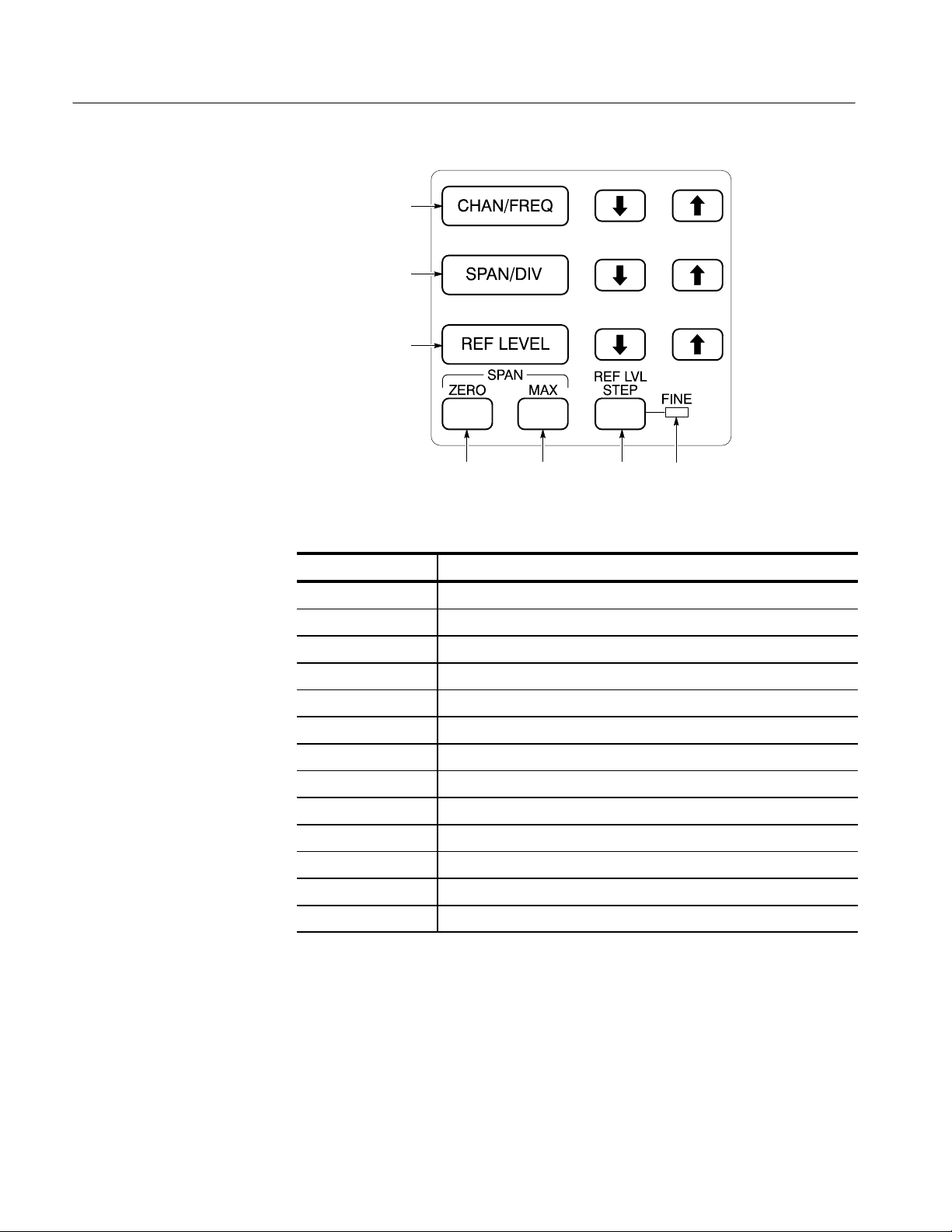
Functional Groups
FREQUENCY, SPAN/DIV,
and REF LEVEL Function
Block
CATV CHAn: FREq
SPAn
REFlvl
ZERosp
MXSpn
REFlvl FINe
T able 3–4: FREQUENCY, SPAN/DIV and REF LEVEL Front Panel Commands
Header Function
CATV CHAn:
FINe Select 1 dB or 10 dB reference level steps.
FINe? Is the reference level step 1 dB or 10 dB?
FREQ Set the center or start frequency.
FREQ? What is the current center or start frequency?
MXSpn Turn MAX SPAN mode on and off.
MXSpn? Is MAX SPAN on or of f?
REFlvl Set/increment/decrement reference level.
REFlvl? What is the reference level?
SPAn Select the frequency span per division.
SPAn? What is the frequency span?
ZERosp Turn ZERO SPAN on and off.
ZERosp? Is ZERO SPAN on or of f?
Select specific channel <num> or next channel <NEXt> in sequence.
3–8
2714 & 2715 Programmer Manual
Page 65

VERT SCALE Function
Block, PLOT, and
READOUT Controls
VRTdsp
Functional Groups
VRTdsp
INPUT Menu
PLOT?
REDout
T able 3–5: VERT SCALE, PLOT, and READOUT Front Panel Commands
Header Function
PLOT? Return screen plot data from the spectrum analyzer.
REDout Turn the on-screen readouts on or off.
REDout? Are on-screen readouts on or off?
VRTdsp Select the vertical scale factor.
VRTdsp? What is the vertical scale factor?
2714 & 2715 Programmer Manual
INPUT MENU
1 PREAMP OFF
3 REF LEVEL UNIT DBUVM
4 1ST MXR INPUT LVL –30DBM
5 RF ATTENUATION AUTO 50DB
6 EXTERNAL ATTEN/AMPL NONE
9 CAL SIG @ 100MHZ –30DBM OFF
PREamp
RLUnit
MXRlvl
ARFatt, RFAtt
ROFset, ROMode
CALsig
3–9
Page 66

Functional Groups
T able 3–6: INPUT Menu Commands
Header Function
ARFatt Turn auto RF attenuation on and off.
ARFatt? Is auto RF attenuation on or off?
ATBl? Provide a listing of an antenna correction table.
CALsig Turn the internal calibration signal on and off.
CALsig? Is the internal calibration signal on or off?
MXRlvl Select first mixer level.
MXRlvl? What is first mixer level?
PREamp Turn the preamp on and off.
PREamp? Is the preamp on or off?
RFAtt Set the RF attenuation to a specific value.
RFAtt? What is the RF attenuation?
RLUnit Select reference level unit.
RLUnit? What is the reference level unit?
ROFset Set the reference level offset and turn it on and off.
ROFset? What is the reference level offset?
ROMode Turn reference level offset mode on and off.
ROMode? Is reference level offset mode on or off?
VMAnttbl Select an antenna table.
VMAnttbl? What antenna table is selected?
VMDIst Select measurement distance in dBmV/m mode.
VMDIst? What is the measurement distance?
VMDEst Select destination register in dBmV/m mode.
VMDEst? What is the destination register?
VMMkrunit Select marker units of dBmV/m or Volts/m in dBmV/m mode.
VMMkrunit? What is the marker unit in dBmV/m mode?
3–10
2714 & 2715 Programmer Manual
Page 67
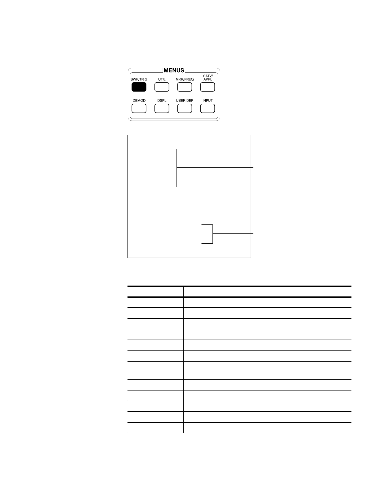
SWP/TRIG MENU
TRIGGER MENU
0 FREE RUN
1 INTERNAL
2 EXTERNAL
3 LINE
4 TV LINE
5 TV FIELD
SWEEP MENU
6 SWEEP RATE 50MS/DIV
7 MANUAL SCAN OFF
8 SYNC POLARITY POSITIVE
9 SETUP TABLE
HORIZONTAL LINE TRIGGERING
0 CONTINUOUS
1 KNOB SELECTABLE
2 KEYPAD ENTERED LINE #
3 KEYPAD ENTRY
4 TV LINE STANDARD abbr.
Functional Groups
T able 3–7: SWP/TRIG Menu Commands
Header Function
Set the sweep rate.
What is the sweep rate?
Select auto, manual, or programmed sweep.
What is the sweep mode?
Select the trigger mode.
What is the trigger mode?
Select the number of the video raster line to trigger on when TV line
triggering is selected.
What is the number of the TV line to trigger on?
Select continuous or programmed TV line trigger.
Is continuous or programmed TV line trigger used?
Select TV standards used in various countries.
What TV standard is being used?
2714 & 2715 Programmer Manual
3–11
Page 68

Functional Groups
T able 3–7: SWP/TRIG Menu Commands (Cont.)
Header Function
VSYnc Select positive or negative video sync polarity .
VSYnc? Is positive or negative sync polarity being used?
SWEEP and RES BW
Function Blocks
RESbw
AREs SIGswp
VFEnab
(see UTIL MENUS key
for VFMode and VIDflt)
TIMe
TIMMode
T able 3–8: SWEEP and RES BW Front Panel Commands
Header Function
AREs Turn AUTO resolution bandwidth on and off.
AREs? Is AUTO resolution bandwidth on or off?
RESbw Select/increment/decrement the resolution bandwidth.
3–12
RESbw? What resolution bandwidth is selected?
SIGswp Select and arm the single sweep mode.
SIGswp? What is the status of the single sweep mode?
TIMe Select/increment/decrement the sweep speed.
TIMe? What is the sweep speed?
TIMMode Select auto, manual, or programmed sweep mode.
TIMMode? What sweep mode is selected?
2714 & 2715 Programmer Manual
Page 69

Functional Groups
DISPLAY STORAGE
Function Block
SAVeMAXHld VIEw
DISPLAY STORAGE
MAX
HOLD
A & B
SAVE
ENABLE
A C D
B
T able 3–9: DISPLAY STORAGE Front Panel Commands
Header Function
MXHld Turn max hold function on and off.
MXHld? Is the max hold function on or off?
SAVe Turn display storage on or off in any or all registers.
SAVe? Is storage on or off in any or all registers?
VIEw Turn display on and off in any or all registers. Also turns waterfall and
B,C minus A modes on and off.
VIEw? What is the display status of any or all registers?
2714 & 2715 Programmer Manual
3–13
Page 70
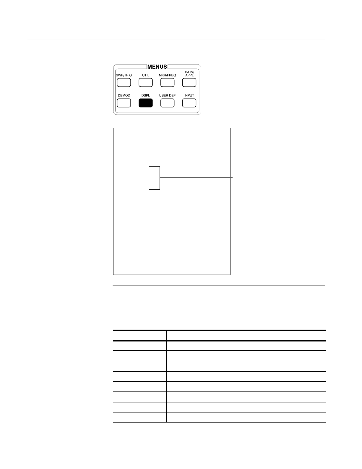
Functional Groups
DSPL Menu
DISPLAY MENU
0 DIGITAL/ANALOG DIGITAL
1 ENSEMBLE AVERAGING
1 INITIATE AVERAGING
2 TERMINATE AVERAGING
3 MAX
4 MEAN
5 MIN
6 MAX/MIN
7 NUMBER OF AVERAGES #
8 SAVE RESULTS IN DISPLAY C
2 B,C MINUS A OFF
3 B,C OFFSET TO CENTER
4 ACQUISITION MODE PEAK
5 TITLE MODE OFF
6 GRATICULE ILLUMINATION ON
7 DISPLAY SOURCE (AM) INTERNAL
8 DISPLAY LINE
1 ON/OFF OFF
2 V ALUE ENTRY 68.8DBMV
3 DISPLAY LINE TO MARKER
4 LIMIT DETECTOR OFF
9 MIN HOLD IN WFM C OFF
AVG
AVG
AVMode
AVNum
AVDest
VIEw Minusa:
POFset
ACQmode
TITLe, TTLMode
GRAt
DSRc
DLIne
DLValue
DLValue
DLLimit
MNHld, MHDest
3–14
NOTE. The TEXt command and TEXt? query, located in the following list, do not
relate directly to a DSPL Menu feature.
T able 3–10: DSPL Menu Commands
Header Function
ACQmode Select peak or max/min acquisition mode.
ACQmode? What is the acquisition mode?
AVDest Select destination register for ensemble averaging.
AVDest? What is the destination register for averaging?
AVG Turn ensemble averaging on and off.
AVG? Is ensemble averaging on or off?
AVMode Select the ensemble averaging mode.
AVMode? What is the ensemble averaging mode?
2714 & 2715 Programmer Manual
Page 71

T able 3–10: DSPL Menu Commands (Cont.)
Header Function
AVNum Select number of sweeps averaged.
AVNum? What is the number of sweeps averaged?
DLIne Turn the display line on and off.
DLIne? Is the display line on or off?
DLLimit Control the limit detector.
DLLimit? What is the limit detector status?
DLValue Set the display line value and turn it on.
DLValue? What is the display line value?
DSRc Select the detection mode.
DSRc? What is the detection mode?
GRAt Turn the graticule light on and off.
GRAt? Is the graticule light on or off?
Functional Groups
MNHld Turn min hold function on and off.
MNHld? Is the min hold function on or off?
MHDest Select the min hold destination waveform.
MHDest What is the min hold destination waveform?
POFset Offset B,C-A mode to center or top of screen.
POFset? Is B,C-A offset to top or center of screen?
TEXt Display the indicated text on line 8 of display.
TEXt? What is the text string being displayed?
TITLe Display the indicated text as a title in title mode.
TITLe? What is the title?
TTLMode Turn title mode on and off.
TTLMode? Is title mode on or off?
VIEw Minusa: Turn B,C MINUS A mode on and off.
2714 & 2715 Programmer Manual
3–15
Page 72
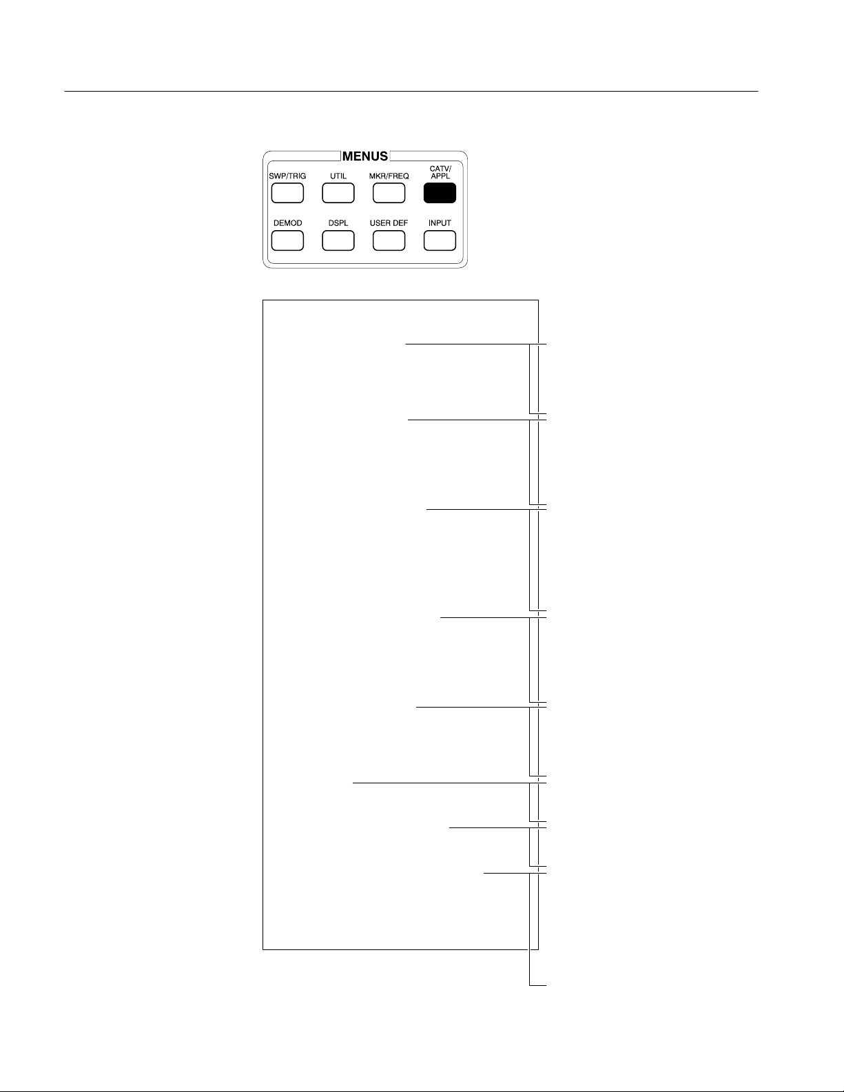
Functional Groups
CATV/APPL Menu
(CATV Mode Active)
CATV MEASUREMENTS (PG 1) CH 23
0 RECENTER CHANNEL 23
1 CARRIER LEVELS
*1 CARRIER LEVEL--AVG POWER
2 CARRIER SURVEY
3 MODULATION DEPTH
4 AURAL (FM) DEVIATION
5 CARRIER TO NOISE
*5 CARR/NOISE--DESIRED/UNDESIRED
6 HUM/LFD
7 FREQUENCY RESPONSE
8 CATV MEASUREMENTS SETUP
9 MORE
*2715 only
CATv CLEvel:FULl
CATv CLEvel:AMPl
CATv CLEvel:FASt
CATv CLVl
CATv STOre:CLVl
CATv SRVey:FULl
CATv SRVey:AMPl
CATv SRVey:FASt
CATv SURv
CATv STOre:SURv
SURv FASt:ON or OFF
CATv DEPth
CATv DPAdj:ON or OFF
CATv DPView
CATv DPTrgt
CATv DPCycl
CATv DPLdur
CATv STOre:DEPth
CATv AURal:AUTo
CATv AURal:PAUse
CATv AURal:ADJust
CATv ADEv
CATv STOre:ADEv
CATv ADInt
CATv CN:AUTo
CATv CN:INServ (2715 Only)
CATv CN:PAUse
CATv STOre:CN
CATv NBW:
CATv HUM
CATv STOre:HUM
CATv LINe:
CATv FRSp:REF
CATv FRSp:NOREF
CATv REFRecall:
CATv CHTbl:
CATv CHDel:
CATv MODE:OFF
CATv SKIp:
CATv ACHan:
CATv SITe:
CATv OPErator
CATv REMove
3–16
2714 & 2715 Programmer Manual
Page 73

CATV MEASUREMENTS (PG 2) CH 23
0 RECENTER CHANNEL 23
*0 ADJACENT CHANNEL LEAKAGE
1 VIEW MODULATION (FIELD)
2 VIEW MODULATION (LINE)
3 VIEW PICTURE
4 LISTEN
5 CTB
6 CSO
7 CROSS MODULATION
8 IN-CHANNEL RESPONSE
9 MORE
*2715 only
Functional Groups
CATv ACL
CATv ACSide:UPper
CATv ACSide:LOWer
CATv ACSide:BOTH
CATv VFIeld:ON or OFF
CATv VLIne:ON or OFF
CATv VPIc:On or OFF
CATv LSTn: ON or OFF
CTFreq
CTDefault
CATv CTB:AUTo
CATv CTB:PAUse
CATv CTB:SINgle
CATv STOre:CTB
CSFreq
CSDefault
CATv CSO:AUTo
CATv CSO:INServ (2715 Only)
CATv CSO:PAUse
CATv CSO:SINgle
CATv CSO:CONt
CSRFreq
CSInt
CSNormal
CATv STOre:CSO
CATv XMOd
CATv STOre:XMOd
CATv XMMode:TDomain or FDomain
(2715 Only)
ICFreq
ICDefault
CATv ICLine:<int> (2715 Only)
CATv ICR:PAUse or CATv ICR
CATv ICR:INServe (2715 Only)
CATv STOre:ICR
2714 & 2715 Programmer Manual
3–17
Page 74

Functional Groups
T able 3–11: CATV/APPL Menu Commands (CATV Mode Active)
Header Function
CATv ACHan: Turn “all channels” mode on or off.
CATv? ACHan What is the on/off status of “all channels” mode?
CATv ACL Performs the adjacent channel leakage test.
CATv? ACL What are the results of the adjacent channel leakage test?
1
1
CATv ACSide Specify which side (UPper, LOWer or BOTh) the adjacent channel
leakage test will be run.
1
CATv? ACSide Will return which side of the adjacent channel leakage test will be
measured.
1
CATv ADEv Perform the aural carrier deviation measurement in the current mode.
CATv? ADEv What are the results of the last aural carrier deviation measurement?
CATv ADInt:<num> Specify the test interval in minutes (10 sec to 24 hours) for the aural
carrier deviation measurement.
CATv? ADInt Will return the current test interval in minutes.
CATv AURal: Specify the aural carrier deviation measurement mode and run the test.
CATv? AURal What are the results of the last aural carrier deviation measurement?
CATv CHAn: Set the channel number.
CATv CHAn? What is the current channel number?
CATv CHDel Delete the specified channel table.
CATv CHTbl: Set the channel table to the one specified.
CATv? CHTbl What is the current channel table?
CATv CLEvel: Specify the carrier levels measurement mode and run the test.
CATv CLVl Perform the carrier levels measurement in the current mode.
3–18
CATv? CLVl What are the results of the last carrier levels measurement?
CATv CN: Perform the specified carrier-to-noise measurement.
CATv? CN What are the results of the last carrier-to-noise measurement?
CATv CTB: Perform the specified CTB measurement.
CATv? CTB What are the results of the last CTB measurement?
CATv? CTDir Return the directory of all loaded channel tables.
CATv CSO: Perform the specified CSO measurement.
CATv? CSO What are the results of the last CSO measurement?
CATv DEPth: Perform the depth of modulation measurement.
CATv? DEPth What are the results of the last depth of modulation measurement?
CATv DPAdj: Turn modulation depth adjustment mode on or off.
1
2715 only.
2714 & 2715 Programmer Manual
Page 75

Functional Groups
T able 3–11: CATV/APPL Menu Commands (CATV Mode Active) (Cont.)
Header Function
CATv DPCycle: Set the cycle delay for the modulation depth adjustment mode.
CATv? DPCycle Return the present cycle delay value for the modulation depth
adjustment mode.
CATv DPLdur: Set the target line duration for the modulation depth adjustment mode.
CATv? DPLdur Return the present target line duration value for the modulation depth
adjustment mode.
CATv DPTrgt: Set the target line for the modulation depth adjustment mode.
CATv? DPTrgt Return the present target line value for the modulation depth
adjustment mode.
CATv DPView: Set the view modulation mode for the modulation depth adjustment
mode.
CATv? DPView Return the present status (FIEld or LINe) of the view modulation mode.
CATv FRSp: Perform the frequency response measurement.
CATv? FRSp What are the results of the last frequency response measurement?
CATv FULLADEv
CATv FULLCLVl
What is the complete response, including header information, of the
specified measurement?
CATv FULLCN
CATv FULLCSO
CATV FULLCTB
CATv FULLDEPth
CATv FULLFRSp
CATv FULLHUM
CATv FULLICR
CATv FULLSURv
CATv FULLXMOD
CATv HUM Perform the hum measurement.
CATv? HUM What are the results of the last hum measurement?
CATv ICLine: Set video line number that test signal resides on for the in-service test.
CATv? ICLine What is the video line number set for the in-service test?
2
CATv ICR: Perform the in-channel response measurement.
2
2714 & 2715 Programmer Manual
CATv? ICR What are the results of the last in-channel response measurement?
CATv LINe: Select 50 Hz or 60 Hz power line frequency.
2
2715 only.
3–19
Page 76

Functional Groups
T able 3–11: CATV/APPL Menu Commands (CATV Mode Active) (Cont.)
Header Function
CATv? LINe What is the current power line frequency?
CATv LSTn: Turn the listen mode on or off.
CATv? LSTn What is the on/off status of listen mode?
CATv MODe: Turn CATV mode on or off.
CATv? MODe What is the on/off status of CATV mode?
CATv NBW Set the noise bandwidth used for carrier-to-noise.
CATv? NBW Return the noise bandwidth used for carrier-to-noise.
CATv OPErator Set the current operator as specified.
CATv? OPErator Return the current operator string.
CATv REFRecall: Recall the specified stored reference.
CATv REMove Remove all CATV -related results from NVRAM.
CATv SITe: Set the current site as specified.
CATv? SITe Return the current site string.
CATv SKIp: Turn skip mode on or of f.
CATv? SKIp What is the on/off status of “all channels” mode?
CATv SRVey: Specify the carrier survey measurement mode, and run the test.
CATv STOre: Store the results of the last measurement specified.
CATv SURv Perform the carrier survey measurement in the current mode.
CATv? SURv What are the results of the last carrier survey measurement?
CATv VFIeld: Turn view modulation (field) mode on or off.
CATv? VFIeld What is the on/off status of view modulation (field) mode?
CATv VLIne: Turn view modulation (line) mode on or off.
CATv? VLIne What is the on/off status of view modulation (line) mode?
CATv VPIc: Turn view picture mode on or off.
CATv? VPIc What is the on/off status of view picture mode?
CATv XMMode: Select the measurement mode for the cross modulaltion measurement
(either Time Domain or Frequency Domain).
CATv? XMMode What is the current cross modulation measurement mode?
3
3
CATv XMOd Perform the cross modulation measurement.
CATv? XMOd What are the results of the last cross modulation measurement?
3–20
CONT RST Provides continuous measurement for a period of 24 hours.
3
2715 only.
2714 & 2715 Programmer Manual
Page 77

Functional Groups
T able 3–11: CATV/APPL Menu Commands (CATV Mode Active) (Cont.)
Header Function
CSFreq Define entries in the AUTO TEST LOCATIONS table used by the CSO
test.
CSFreq? Return the auto test table.
CSDefault Default value.
CTFreq Define entries in the AUTO TEST LOCA TIONS table used by the CTB
test.
CTFreq? Return the auto test table.
CTDefault Default value.
FCOr? What are the frequency correction values?
FCMode ON returns flatness correction values. OFF returns 0.0.
FCMode? What is the status of FCMode (on or off)?
ICFreq Define entries in the AUTO TEST LOCA TIONS table used by the
In-Channel Response test.
ICFreq? Return the auto test table.
ICDefault Recall the default values for the AUTO TEST LOCA TIONS table used
by the In-Channel Response test.
SURv FASt: Turn the fast carrier survey mode on or off.
SURv? FASt What is the on/off status of the fast carrier survey mode?
2714 & 2715 Programmer Manual
3–21
Page 78

Functional Groups
CATV/APPL Menu
(CATV Mode Inactive)
APPLICATION MENU
0 BANDWIDTH MODE @ –3DBC
1 CARRIER TO NOISE @ 5.0MHZBW
2 NOISE NORM’D @ 1.0HZBW
3 SIGNAL SEARCH MENU
0 BEGIN FREQ 88.000MHZ
1 END FREQ 108.000MHZ
2 START TEST
3 DISPLAY RESULTS # SIGNALS
4 OCCUPIED BW @ 99%
7 FM DEVIATION MODE
8 CATV MEASUREMENT MODE
9 SETUP TABLE
0 DB DOWN FOR BW MODE –3DBC
1 NORM BW FOR C/N 5.0MHZBW
2 NOISE NORM’D BW 1.0HZBW
3 PERCENT OCCUPIED BW 99%
BWMode
CNMode
NNMode
SSBegin
SSEnd
SGSrch
SSResult?
OBWpcnt
CATv:ON
BWNum
CNBw
NNBw
NOTE. BWResult?, CNResult?, and NNResult? return results normally displayed
on the screen.
3–22
2714 & 2715 Programmer Manual
Page 79

T able 3–12: CATV/APPL Menu Commands (CATV Mode Inactive)
Header Function
BWMode Turn bandwidth mode (BW)) on and off.
BWMode? Is bandwidth (BW) mode on or off?
BWNum Set the number of dB down for BW mode.
BWNum? What is the dB down setting in BW mode?
BWResult? What is the bandwidth at the specified dB down?
CATv Set CATV control parameters.
CATv? Return the CATV control parameter status.
CNBw Set noise bandwidth for carrier-to-noise (C/N) mode.
CNBw? What is the noise bandwidth in C/N mode?
CNMode Turn carrier-to-noise mode on and off.
CNMode? Is carrier-to-noise mode on or off?
CNResult? What is the C/N ratio?
Functional Groups
DSRc Set the detection mode.
DSRc? What is the detection mode?
NNBw Set the noise bandwidth for normalized noise mode.
NNBw? What is the noise bandwidth in normalized noise mode?
NNMode Turn normalized noise mode on and off.
NNMode? Is normalized noise mode on or off?
NNResult? What is the normalized noise in the specified bandwidth?
OBWMode Set occupied bandwidth mode to on, off or idle.
OBWMode? Is the occupied bandwidth mode on, off or idle?
OBWpcnt Set percent (1 to 99%) occupied bandwidth.
OBWpcnt? Return the current occupied bandwidth percent.
OBWResult? Return the results (Hz) of the most recent occupied bandwidth
measurement.
SSBegin Set the beginning signal search frequency.
SSBegin? What is the beginning signal search frequency?
SSEnd Set the ending signal search frequency.
SSEnd? What is the ending signal search frequency?
SGSrch
Search for signals greater than threshold (THRhld) between beginning
and ending search frequencies.
2714 & 2715 Programmer Manual
SSResult? What is the result of the signal search?
3–23
Page 80

Functional Groups
UTIL Menu
UTILITY MENU
1 STORED SETTINGS/DISPLAYS
2 KEYPAD ENTERED SETTINGS
5 VIDEO FILTER WIDE
3 NORMALIZATIONS
4 SYSTEM CONFIGURATION
1 SCREEN PLOT CONFIGURATION
2 COMMUNICATION PORT CONFIG
3 INSTRUMENT CONFIGURATION
1 MINIMUM SIGNAL SIZE 20
4 PHASELOCK ON
5 FREQUENCY CORRECTIONS ON
4 REAL-TIME CLOCK SETUP
0 SET DAY
1 SET MONTH
2 SET YEAR
3 SET HOUR
4 SET MINUTE
5 SET SECONDS TO :00
6 DISPLAY DATE/TIME ON
5 STORED SETTINGS PROTECT OFF
6 FILE SYSTEM DIRECTORY
9 INSTALLED OPTIONS DISPLAY
5 INSTR DIAGNOSTICS/ADJUSTMENTS
6 SERVICE REQUEST
RECall
STOre
ERAse
VFMode, VIDflt
NORM
PTYpe
RS232
PKHeight
PLLmode
DIScor
DATe
RTIme
CLOck
PROTset
DIR?
ID?
RQS
3–24
T able 3–13: UTIL Menu Commands
Header Function
DIR? Return a spectrum analyzer file system directory.
DIScor Turn the frequency corrections on and off.
DIScor? Are the frequency corrections on or off?
DATe Set the real-time clock date.
DATe? What is the real-time clock date?
DATIme? What is the time of day?
CLOck Turn the date and time display on or off.
CLOck? Is the date and time display on or off?
ERAse Erase the stored settings in a particular register.
2714 & 2715 Programmer Manual
Page 81

Functional Groups
T able 3–13: UTIL Menu Commands (Cont.)
Header Function
ID? List the 2714 or 2715’s firmware version and installed options.
INIT Reset to user-defined or factory power-up settings.
NORM Carry out the indicated normalizations.
NORM? Return a list of current normalization parameters.
PKHeight Set the minimum signal height for marker functions.
PKHeight? What is minimum signal height for marker functions?
PLLmode Turn phase lock on and off.
PLLmode? Is phase lock on or off?
PROTset Turn stored settings files protection on and off.
PROTset? Is stored settings files protection on or off?
PTYpe Specify the plotter type for screen plots.
PTYpe? What is the specified plotter type?
RECall Recall a stored settings file.
RTIme Set the real-time clock time.
RTIme? What is the real-time clock time?
RS232 Set RS-232 communications parameters.
RS232? Return all RS-232 communications parameters.
STOre Store the current settings in a stored settings file.
VFMode Selects auto or fixed video filter mode.
VFMode? Is auto or fixed video filter mode selected?
VIDflt Sets and turns the video filter on and off.
VIDflt? What video filter is selected?
2714 & 2715 Programmer Manual
3–25
Page 82

Functional Groups
DEMOD Menu
DEMOD MENU
0 OFF
1 AM DEMODULATOR
2 FM DEMODULATOR
3 BROADCAST (AM) VIDEO
9 VIDEO SETUP MENU
0 VIDEO DETECT MODE BROADCAST
1 SYNC POLARITY POSITIVE
2 VIDEO POLARITY NEGATIVE
DETector
VMOnitor
VDMode
VSYnc
VPOlarity
T able 3–14: DEMOD Menu Commands
Header Function
DETector Turn on/select which audio detector is used.
DETector? Which audio detector is being used?
VDMode Select broadcast or satellite video demodulation.
VDMode? Is broadcast or satellite video demodulation used?
VMOnitor Turn the video monitor on or off.
VMOnitor Is the the video monitor on or off?
VPOlarity Select positive or negative video polarity.
VPOlarity? Is positive or negative video polarity selected?
VSYnc Select positive or negative video sync polarity.
VSYnc? Is positive or negative sync polarity being used?
3–26
2714 & 2715 Programmer Manual
Page 83

Functional Groups
Curve and Waveform
Commands
System-Related
Commands
Waveform transfers are not reflected on any menu or function block. They
transfer data representing on-screen spectra and their formatting between the
2714 or 2715 and the controlling computer.
T able 3–15: Curve and Waveform Commands
Header Function
CURve
CURve? Transfer waveform data from the specified register or from the register
WAVfrm?
WFMpre Specify source or destination register used for transferring waveform
WFMpre? Request the complete waveform preamble or ask which register and
Transfer waveform data to the register specified by WFMpre, using the
encoding set by
set with WFMpre, using the encoding specified by the WFMpre
command.
Same as WFMPRE? followed by CURVE?.
data with the CURve command or query. Also, specify the encoding to
be used on the waveform data.
encoding are to be used for waveform transfers.
WFMpre.
These commands and queries are independent of any spectrum analyzer menu or
function block. They represent functions that affect the interaction of the
spectrum analyzer and the GPIB controller or the RS-232 interface.
T able 3–16: System-Related Commands
Header Function
EOS Enable and disable SRQ on end-of-sweep.
EOS? Is SRQ enabled or disabled at end-of-sweep?
ERR? What is the error code?
EVEnt? What is the event code?
GTL Go to local operation.
HDR Turn the response header on and off.
HDR? Is the response header on or off?
HELp? 2714 or 2715 sends a list of valid GPIB command headers.
MSGdlm Select semicolon or line feed as response delimiter.
MSGdlm? What is the response delimiter?
RQS Enable or disable SRQs (except power-on SRQ).
RQS? Are SRQs enabled or disabled?
RST Perform a Device Clear operation.
2714 & 2715 Programmer Manual
3–27
Page 84

Functional Groups
T able 3–16: System-Related Commands (Cont.)
Header Function
SET? What are the current spectrum analyzer settings?
SGErr Enable/disable SRQ when marker cannot find a signal.
SGErr? Is marker-cannot-find-signal SRQ enabled or disabled?
STByte? Return GPIB serial poll status byte.
WAIt Command the spectrum analyzer to wait for the end of sweep.
Miscellaneous Commands
The remaining commands include a set of miscellaneous commands and those
which support on-screen menu definition and item selection. Refer to Program-
ming for an example of how these commands are used to create an interactive
menu on the 2714 or 2715’s display screen.
T able 3–17: Miscellaneous Commands
Header Function
CLRMenu Clear the menu on the 2714 or 2715’s screen.
CLRKey Clear the last key pressed.
DEFMenu Write a menu on the 2714 or 2715’s screen.
FILE Store a binary block under a given file name.
FILE? Return the named file as a binary block.
KEY Simulate pressing a key.
KEY? Return the identity of the last key pressed.
MEMory? How much NVRAM is free?
PRDouts? Return the 2714 or 2715’s on-screen readouts.
UDPDir? Return list of currently loaded User Defined Programs.
3–28
2714 & 2715 Programmer Manual
Page 85

Command/Query
Page 86

Page 87

Command and Query Definitions
This section contains an alphabetical listing of all instrument-specific commands
and queries. The list defines each command or query. In addition, it contains all
the information needed to send messages to the 2714 or 2715, or to interpret the
responses from the 2714 or 2715.
Typographical Conventions
Each 2714 or 2715 command is discussed in the following format:
COMmand <arg> (if no argument is needed, <arg> is omitted)
Arguments: Argument 1, argument 2, ...
(If no argument is required, “None” is listed.)
Uppercase letters are required when entering the first three (sometimes four)
letters of a command or query. Lowercase letters may be used for the remaining
data if desired. Letters other than those shown in this manual will not be
accepted by the 2714 or 2715.
Following each command is a general discussion of its arguments, specific
precautions, and other important information.
Actual messages are shown in their correct syntax. When the number of possible
messages is limited (such as commands that turn features on and off), all
messages are shown as in the following example:
COMmand ON
COMmand OFF
Where there is a large range of arguments (such as numeric values), typical
examples are shown as in this example:
COMmand 10.5 kHz (for example)
Typical examples are always followed by this phrase:
(for example)
Each query is discussed in the following format:
QUEry? <arg> (In most cases no argument is needed, and <arg> is omitted.)
Arguments: Argument 1, argument 2, ...
2714 & 2715 Programmer Manual
(If no argument is required, “None” is listed.)
4–1
Page 88

Command and Query Definitions
Following each query is a general discussion of its arguments, specific precautions, and other important information. A detailed description of the response to
the query is also provided.
The query is shown along with its arguments. The spectrum analyzer response is
shown indented on the following line. The response is always shown assuming
that HDR ON is selected as in the following example:
QUEry?
QUERY ON
QUERY OFF
All responses are shown when the number of possible responses is limited (such
as queries that report the on/off status of features). When a large range of
responses is possible (such as numeric values), typical examples are shown as in
this example:
QUERY?
QUERY 10.500E+3 (for example)
Typical examples are always followed by this phrase:
(for example)
4–2
2714 & 2715 Programmer Manual
Page 89

List of Commands and Queries
The following list of commands and queries provides detailed information about
the 2714 or 2715 instruction set. This section does not attempt to explain the
operation of the spectrum analyzer. Refer to the user manual for the 2714 or
2715 for descriptions of the 2714 or 2715 or its features and functions.
Command and Query Definitions
ACQmode <arg>
ACQmode?
AREs <arg>
Arguments: MAXMin, PEAK
This single-argument command designates the display storage acquisition mode.
ACQmode PEAK
ACQmode MAXMin
Arguments: None
This simple query returns the currently selected acquisition mode.
ACQmode?
ACQMODE PEAK
ACQMODE MAXMIN
Arguments: ON, OFF
This single-argument command turns automatic selection of resolution band-
width on and off.
AREs ON
AREs?
2714 & 2715 Programmer Manual
Arguments: None
This simple query returns the status of automatic resolution bandwidth selection
mode.
AREs OFF
AREs?
ARES ON
ARES OFF
4–3
Page 90

Command and Query Definitions
ARFatt <arg>
ARFatt?
ATBI? <arg>
Arguments: ON, OFF
This single-argument command turns automatic selection of RF attenuation on
and off. The attenuation, linear scale factor, and reference level may change
when auto selection is turned on, but not when auto selection is turned off.
ARFatt ON
ARFatt OFF
Arguments: None
This simple query returns the status of automatic RF attenuation selection.
ARFatt?
ARFATT ON
ARFATT OFF
Arguments: None, integer in range of 1 to 5
This is a query with one or no argument that returns a listing of the specified
antenna table. The argument is the number of the antenna table to be listed. If a
number outside the range is indicated, the last table in the range is returned (for
instance, an argument of 6 returns table number 5, an argument of 0 returns table
number 1). If no argument is specified, the currently selected table is returned.
ATBl? 3
ATBL ANTENNA 3
Cal Distance = 3.0 Meters
Frequency Factor(dB)
-------------------------
100.0MHz ąą1.0
200.0MHz ąą2.0
300.0MHz ąą3.0
ąą: ąąą:
ą1.8GHz ă18.0
------------------------";ą(for example)
4–4
2714 & 2715 Programmer Manual
Page 91

Command and Query Definitions
ATHrhld <arg>
ATHrhld?
AVDest <arg>
Arguments: ON, OFF
This single-argument command turns automatic selection of signal threshold on
and off. The threshold may change when auto selection is turned on, but not
when it is turned off.
ATHRHLD ON
ATHRHLD OFF
Arguments: None
This simple query returns the status of automatic signal threshold selection.
ATHrhld?
ATHrhld ON
ATHrhld OFF
Arguments: A, B, C
This single-argument command designates the spectrum analyzer display register
used as the destination for ensemble average and minimum hold operations. The
destination register cannot be changed while a MIN Hold or ensemble average
operation is in progress.
AVDest?
AVDest A
AVDest B
AVDest C
Arguments: None
This simple query returns the spectrum analyzer display register currently
selected as the destination for MIN Hold and ensemble average functions.
AVDest?
AVDEST A
AVDEST B
AVDEST C
2714 & 2715 Programmer Manual
4–5
Page 92

Command and Query Definitions
AVG <arg>
AVG?
AVMode <arg>
Arguments: ON, OFF
This single-argument command turns the currently selected ensemble averaging
mode on and off. Ensemble averages will terminate after the requested number of
sweeps are averaged, but AVG OFF is used to terminate a continuous average.
Ensemble averaging cannot be turned on if the analog display mode is active, or
if there is a destination register conflict.
AVG ON
AVG OFF
Arguments: None
This simple query returns the on/off status of the currently selected ensemble
averaging mode.
AVG?
AVG ON
AVG OFF
Arguments: MAX, MAXMin, MEAN, MIN
AVMode?
This single-argument command designates the ensemble average mode.
AVMode MAX
AVMode MAXMin
AVMode MEAN
AVMode MIN
Arguments: None
This simple query returns the currently selected ensemble averaging mode.
AVMode?
AVMODE MAX
AVMODE MAXMIN
AVMODE MEAN
AVMODE MIN
4–6
2714 & 2715 Programmer Manual
Page 93

Command and Query Definitions
AVNum <arg>
AVNum?
BWMode <arg>
Arguments: Integer number in the range of 0 to 1024
This single-argument command designates the number of sweeps to be averaged
by the currently selected ensemble averaging mode. If zero is specified, a
continuous average is performed. The default is 16.
AVNum 128
Arguments: None
This simple query returns the integer number of sweeps the current ensemble
averaging mode will average.
AVNum?
AVNUM 128
Arguments: ON, OFF, IDLE
This single-argument command turns the spectrum analyzer bandwidth
measurement mode on and off. When bandwidth mode is turned on, marker
modes are turned off if they were previously enabled. Bandwidth mode is not
allowed if the spectrum analyzer is in analog display mode or Video Monitor
mode. Bandwidth mode cannot be enabled for waveforms in the D-register if
waterfall mode is enabled.
(for example)
(for example)
BWMode?
BWMode ON
BWMode OFF
BWMode IDLE
BWMode IDLE has the same effect as BWMode ON.
Arguments: None
This simple query returns the status of the bandwidth measurement mode.
BWMode?
BWMODE ON
BWMODE OFF
BWMODE IDLE
2714 & 2715 Programmer Manual
4–7
Page 94

Command and Query Definitions
BWNum <arg>
BWNum?
BWResult?
Arguments: Integer in the range –1 to –70
This single-argument command specifies the integer number of decibels (dB)
below the signal peak at which the bandwidth measurement mode measures
bandwidth. Units are not allowed and dBc units are assumed. Non-integer values
are truncated.
BWNum -20 (for example)
Arguments: None
This simple query returns the integer value of decibels (dB) below the peak at
which a signal’s bandwidth will be measured by the spectrum analyzer’s
bandwidth measurement mode.
BWNum?
BWNUM -20
Arguments: None
This simple query returns the result of the most recent bandwidth measurement
in hertz (using the spectrum analyzer’s bandwidth measurement feature). The
result is updated at the end of the current sweep if bandwidth mode is not idle.
(for example)
CALSig <arg>
CALSig?
BWResult?
BWRESULT 5.238E+3
Arguments: ON, OFF
This single-argument command turns the calibration signal on and off. The RF
input signal is disconnected when the calibration signal is turned on.
CALSig ON
CALSig OFF
Arguments: None
This simple query returns the on/off status of the calibration signal.
CALSig?
CALSIG OFF
CALSIG ON
(for example)
4–8
2714 & 2715 Programmer Manual
Page 95

Command and Query Definitions
CATv <arg>
Arguments: See Table 4–1
This multi-argument command configures CATV measurements. Commands are
implemented by entering the CATv command followed by the desired CATV
function. For example, the command
CATv MODe:ON
enables the CATV mode.
When running a CATV measurement routine (such as CTB:AUTo), the 2714 or
2715 pauses when prompts appear on its screen. The pause generates event code
403, which must be cleared before the measurement will continue. A pause may
be cleared by any of these methods:
H CONTinue resumes the test
H RST stops the test
H For RS-232, assert a break condition
H For GPIB, send a DCL command
NOTE. The 2714 or 2715 is paused during measurement routines for various
reasons, such as changing signal connections. To ensure accurate test results,
carry out the operation indicated by the screen prompt before continuing
program execution.
Descriptions of the following CATV-related commands can be found later in this
section (listed in alphabetical order):
CTFreq ICFreq
CTFreq? ICFreq?
CTDefault ICDefault
CSFreq SURv (FAST:)
CSFreq? SURv?
CSDefault
2714 & 2715 Programmer Manual
4–9
Page 96

Command and Query Definitions
T able 4–1: CATv Command Arguments
Argument Function
ACHan:ON Turn all channels mode on. Skip status will be ignored.
ACHan:OFF Turn all channels mode off. Skip status will be honored.
1
ACL
ACSide:UPper
ACSide:LOWer
ACSide:BOTh
1
ADEv Perform the aural carrier deviation measurement in the current mode.
ADInt:<num> Where <num> is a number from 10/60 to 1440 specifying the duration
Performs the adjacent channel leakage test.
1
Runs the adjacent channel leakage test on the higher frequency
channel.
1
Runs the adjacent channel leakage test on the lower frequency
channel.
Runs the adjacent channel leakage test on both the higher and lower
frequency channels.
This only works on CATV or FM channel types; otherwise event code
900 (FUNC NOT AVAILABLE ON THIS CHAN TYPE) is generated.
of the aural deviation test interval in minutes (from 10 sec. to 24 hours).
AURal:ADJust Will enter the aural deviation “real time” ADJUSTMENT mode. Use
RST, RS-232 BREAK or GPIB DCL to leave this mode. Measurement
results will be discarded.
AURal:AUTo Will run the aural deviation test in AUTO mode. While the test is
running, CONtinue will cause the test to terminate and compute and
save the measurement to that point. RST, RS-232 BREAK or GPIB
DCL commands will cause the measurement to abort with the results
discarded.
AURal:PAUse Will run the aural deviation test in INTERACTIVE mode. While the test
is running, CONtinue will cause the test to terminate and compute and
save the measurement to that point. RST, RS-232 BREAK or GPIB
DCL commands will cause the measurement to abort with the results
discarded. Event code 403 (USER REQUEST OR CATV PROMPT) is
generated after the measurement is complete. Use CONTinue to
resume execution, or terminate the measurement with the RST
command, an RS-232 BREAK, or a GPIB DCL command.
CHAn:NEXt Go to the next entry in the channel table. Skip status is honored unless
all channels mode is active. Channel number wraps to the beginning if
at the end of the table.
CHAn:<num>
Sets the current channel number to <num> and installs the base
settings for this channel. Channel numbers from 0 to 999 are accepted.
Skip status is always ignored.
Event code 801 and the message RANGE ERROR is returned if the
channel is not defined in the current channel table. The channel
number remains unchanged under these circumstances.
4–10
1
2715 only.
2714 & 2715 Programmer Manual
Page 97

Command and Query Definitions
T able 4–1: CATv Command Arguments (Cont.)
Argument Function
CHAn:PREv Go to the previous entry in the channel table. Skip status is honored
unless all channels mode is active. Channel number wraps to the end if
at the beginning of the table.
CHDel: The channel table <name> is deleted from the instrument. <name>
must be delimited with quotes (”). Event code 738 (STORAGE
REGISTER EMPTY) is returned if the named channel is not found.
The built-in tables STD, HRC, and IRC are always available. When
deleted, these tables are removed from nonvolatile memory. However,
they always appear within the CTDir? query response because they
are constructed from permanent ROM-based data.
CHTbl:<name> The current channel table is set to the specified name. The name must
be delimited with quotes (”).
Event code 777 (DEFAULT DAT A LOADED) is returned if there is no
channel with the specified name. Under these conditions the channel
table is changed to the default (STD) table. The channel number is
changed to the number that was active the last time this table was
selected, or to the first channel for new tables.
CLEvel:FULl
CLEvel:AMPl
CLEvel:FASt
CLVl Perform the carrier levels measurement in the current mode.
CN:AUTo Perform the fully automatic carrier-to-noise measurement.
CN:INServ Sets the carrier-to-noise mode to Auto and runs an in-service test.
CN:PAUse Perform the semiautomatic carrier-to-noise measurement. This
Perform the carrier level measurement in the following manner:
CLEvel:FULl – set mode to ACCURATE FREQUENCY AND AMPL and
run test.
CLEvel:AMPl – set mode to ACCURATE AMPLITUDE ONLY and run
test.
CLEVel:FAST – set mode to FAST AMPLITUDE ONLY and run test.
If the current channel is identified in the channel table as DIGITAL,
then the accuracy modes are irrelevant. The instrument will run the
average power measurement.
If the current channel is identified in the channel table as DIGITAL,
then the accuracy modes are irrelevant. The instrument will run the
average power measurement.
command adds a pause to the fully automatic carrier-to-noise
measurement just before the noise is measured. Y ou may change
equipment setup, but you cannot adjust the 2714 or 2715 controls. The
measurement proceeds after you respond to the prompt.
If the current channel is identified in the channel table as DIGITAL,
then CN:PAUse will run the desired-to-undesired measurement.
1
2714 & 2715 Programmer Manual
CSO:AUTo Perform the automatic CSO measurement.
1
2715 only.
4–11
Page 98

Command and Query Definitions
T able 4–1: CATv Command Arguments (Cont.)
Argument Function
CSO:CONt Perform the continuous CSO measurement. Event code 909 (NO BEA T
FREQUENCIES ARE DEFINED) is returned if all beat frequencies
have been deleted from the setup table.
CSO:INServ Sets the composite second order (CSO) mode to Auto and runs an
in-service test.
CSO:PAUse Perform the semi-automatic CSO measurement. In this mode the 2714
or 2715 pauses after measuring the carrier level. It then issues event
401 (prompts user to turn off carrier or modulation). A CONT command
is then required to continue the measurement sequence. RST will abort
the measurement.
CSO:SINgle Perform the single-sweep version of the CSO measurement, which
minimizes carrier-off time. In this mode the 2714 or 2715 pauses and
generates event code 403 (USER REQUEST OR CATV PROMPT)
after measuring the carrier. The user is then prompted to turn the
carrier off. A single sweep is then performed between the lowest and
highest frequencies in the auto test table (absolute values are ignored).
Another event code 403 is generated to prompt the user to turn the
carrier on. The measured results are the highest amplitudes detected
within a ±50 kHz window around each frequency specified in the auto
test table.
CTB:AUTo Perform the automatic CTB measurement.
1
CTB:PAUse Perform the semi-automatic CTB measurement. In this mode the 2714
or 2715 pauses after measuring the carrier level. It then issues event
401 (prompts user to turn off carrier or modulation). A CONT command
is then required to continue the measurement sequence.
CTB:SINgle Perform the single-sweep version of the CTB measurement, which
minimizes carrier-off time. In this mode the 2714 or 2715 pauses and
generates event code 403 (USER REQUEST OR CATV PROMPT)
after measuring the carrier. The user is then prompted to turn the
carrier off. A single sweep is then performed between the lowest and
highest frequencies in the auto test table (absolute values are ignored).
Another event code 403 is generated to prompt the user to turn the
carrier on. The measured results are the highest amplitudes detected
within a ±50 kHz window around each frequency specified in the auto
test table. RST will abort the measurement.
DEPth Perform the depth of modulation measurement.
DPAdj Invoke or cancel the modulation depth adjustment mode. The
selections are ON or OFF. KEY TERMW and KEY TERMZ can also be
used to cancel the mode.
DPCycl Sets up the cycle delay for the modulation depth adjustment mode. The
range of values is 0 to 30,000.
DPLdur:<num> Sets up the target line duration for the modulation depth adjustment
mode. The range of values is 0.0 to 100.0%.
4–12
2714 & 2715 Programmer Manual
Page 99

Command and Query Definitions
T able 4–1: CATv Command Arguments (Cont.)
Argument Function
DPTrgt Sets up the target line for the modulation depth adjustment mode. The
range of values is 0.0 to 100.0%
DPView Sets up the view modulation mode for the modulation depth adjustment
mode. The selections are either FIEld or LINe.
FRSp:REF
Perform the frequency response measurement.
(or NORef)
HUM Perform the hum measurement.
ICLine:<int> Sets the video line number on which the test signal for the in-service,
in-channel response test resides. The argument can be an integer from
1 to 1023 or a –1. A value of –1 designates that no test signal exists so
the in-service test will abort.
1
ICR Perform the in-channel response measurement.
ICR:INServ Sets ICR mode to auto and runs an in-sevice test.
1
ICR:PAUse Equivalent to the ICR listed previously; perform the in-channel
response measurement.
LINe:50 Select 50 Hz power line frequency.
LINe:60 Select 60 Hz power line frequency.
LSTn:OFF Turn listen mode off.
LSTn:ON Set listen mode to on so you can listen to demodulated audio.
MODe:OFF Turn CATV mode off.
MODe:ON Turn CATV mode on. The 2714 or 2715 will tune to the last active
channel and install the base settings.
NBW:<num> Set the noise bandwidth used for carrier-to-noise measurements to
<num>. The range is 1 Hz to 1800 MHz. 4 MHz is the default value.
2714 & 2715 Programmer Manual
OPEraĆ
tor:<string>
The current operator is set to <string> delimited by quotes (”). Only
the first 28 characters are saved.
REFRecall:<num> Recall the stored reference <num>.
REMove Remove all CATV-related results from NVRAM.
SITe:<string> The current site is set to <string> delimited by quotes (""). Only the
first 28 characters are saved.
SKIp:OFF Turn skip status OFF for the current channel.
SKIp:ON Set skip status ON for the current channel.
1
2715 only.
4–13
Page 100

Command and Query Definitions
T able 4–1: CATv Command Arguments (Cont.)
Argument Function
STOre:ADEv
STOre:CLVl
STOre:CN
STOre:CSO
STOre:CTB
STOre:DEPth
STOre:FRSp
STOre:HUM
STOre:ICR
STOre:SURv
STOre:XMOd
Store the results of the last measurement in NVRAM.
For example, the command
STOre:CN
stores the results of the last carrier-to-noise measurement.
SRVey:FULl
SRVey:AMPl
SRVey:FASt
Perform the carrier survey measurement in the following manner:
SRVey:FULl – set the mode to ACCURATE FREQUENCY AND AMPL
and run the test
SRVey:AMPl – set the mode to ACCURATE AMPLITUDE ONLY and
runt the test
SRVey:FASt – set the mode to FAST AMPLITUDE ONLY and run the
test
SURv Perform the carrier survey measurement in the current mode.
VFIeld:OFF Set view modulation (field) mode to OFF.
VFIeld:ON Set view modulation (field) mode to ON. This mode allows you to view
base-band video in the time domain (as an oscilloscope display).
Triggering and sweep speed are automatically set to display one
complete video field.
VLIne:OFF Set view modulation (line) mode to OFF.
VLIne:ON Set view modulation (line) mode to ON. This mode allows you to view
base-band video in the time domain (as an oscilloscope display). The
knob is assigned to select which video line (nearest left edge of screen)
triggers the display. The default line is the VITS line, or line 17 if no
VITS line is identified by the channel table.
VPIc:OFF Set view picture mode to OFF.
VPIc:ON Set view picture mode to ON. This mode allows you to view a
demodulated television picture on the 2714 or 2715’s screen.
4–14
XMMode:FDomain Sets the measurement mode for the cross modulation measurement to
the frequency domain method.
1
XMMode:TDomain Sets the measurement mode for the cross modulation measurment to
the time domain (NCTA) method.
1
XMOd Perform the cross-modulation measurement.
1
2715 only.
2714 & 2715 Programmer Manual
 Loading...