

Page 1

T.O. 33K3-4-2400-l
TECHNICAL MANUAL
CALIBRATION PROCEDURE
FOR
SPECTRUM ANALYZER
27100
(TEKTRONIX)
Distribution Statement - Distribution authorized to U. S. Government agencies and their contractors for
official use or for administrative or operational purposes only, 30 June 1989.
document shall be referred to AFMETCAL Detachment l/MLLW, 813 Irving-Wick Dr W, Suite 4M,
Heath, OH 43056-6116.
Destruction Notice - For unclassified, limited documents, destroy by any method that will prevent
disclosure of the contents or reconstruction of the document.
Published under Authority of the Secretary of the Air Force
Other requests for this
30AUGUST1996
CHANGE 3 - 30 JANUARY 2002
Page 2
T.O. 33K3-4-2400-1
INSERT LATEST CHANGED PAGES. DESTROY SUF’JZRSEDED PAGES.
LIST OF EFFECTIVE
Date of issue for original and changed pages are:
Original .................... 0.. ................... .30 August 1996
Change.. .................... l....... ................... .30 July 1997
Change.. .................... 2 .......................... 30 May 1998
Change.. ................... .3.. ................... 30 January 2002
TOTAL NUMBER OF PAGES IN THIS PUBLICATION IS 16, CONSISTING OF THE FOLLOWING:
NOTE: intheoutamarginsofthepagc,
The portion of the text and illustrations affeded by the changes is indicated by a vertical line
Page * Change
No. No.
Title.. ............................... 3
A ..................................... 3
1 - 7.. ............................... 0
8 ...................................... 3
9 - 11 ............................... 0
12.. .................................. 1
13.. .................................. 2
14 Blank.. ........................ 0
Page
No.
* Change
No.
Page
No.
* Change
No.
A Change3
USAF
Page 3

T.O. 33K3-4-2400-1
SPECTRUM ANALYZER
2710 ( )
(TEKTRONIX)
1 CALIBRATION DESCRIPTION:
Table 1.
Test Instrument (TI) Performance Test
Characteristics Specifications Method
Center Frequency Range: 10 kHz to 1.8 GHz Compared to a Frequency
Standard
Accuracy: Standard TI
1 X 10⁻⁵ of Center Frequency ±5 kHz;
OPT 01 TI 5 X 10⁻⁷ of Center Frequency
±700 Hz;
OPT 02 TI (Counter) 1 X 10⁻⁵ of Center
Frequency ±10 Hz ±LSD for Counter;
OPT 01/02 TI (OPT 01 Time Base,
OPT 02 Counter) 5 X 10⁻⁷ ±10 Hz ±LSD
Calibrator Range: 100 MHz at -30 dBm Power level checked with
Power Meter. Frequency
Accuracy: Power ±0.3 dB, Frequency checked with Electronic
±5 kHz, OPT 01 ±2 kHz Counter
Frequency Span Range: 0 Hz to 1.8 GHz 0 Hz in Zero Compared to standard
Span 1.8 GHz in Full Span Plus 10 kHz comb tooth signals from
to 100 MHz/div (Opt 01, 1 kHz to a Marker or Comb
100 MHz/div) in a 1, 2, 5 sequence Generator measured over
center 8 divs
Accuracy: ±3.0% of the Span setting
over center eight divisions
Sweep Time Range: 1 to 2.0 sec/div Compared to a Time
over center eight divisions Mark Generator
Accuracy: ±10% over center 8 divisions
Bandwidth Range: 6 dB bandwidths 3 kHz to Compared to the CAL
5 MHz (also 300 Hz for OPT 01) OUTPUT STD signal
source
Accuracy: Shape Factor ≤7:1
(≤6:1 serial numbers B010001 to
B010318)
RF Attenuator Range: 0 dB to 50 dB in 2 dB steps Not Spec'ed by
Manufacturer
Accuracy: N/A Operational Check only
1
Page 4

T.O. 33K3-4-2400-1
Table 1. (Cont.)
Test Instrument (TI) Performance Test
Characteristics Specifications Method
Frequency Response Range: 0 to 1.8 GHz Leveled signal source is
(Flatness) varied over the frequency
Accuracy: 3 dB (±1.5 dB about the bands
midpoint between two extremes)
Log/Lin Display Range: LOG 10, 5 and 1 dB/div and Compared to a Standard
Linear Attenuator Measurement
Receiver
Accuracy: LOG 10;
±1.0 dB/10 dB to a maximum
cumulative error of ±2.0 dB from 0 dB
to 70 dB, ±2.0 dB/10 dB from 70 dB to
80 dB
Accuracy: LOG 5;
±1.0 dB/5 dB to a maximum of ±2.0 dB
over 40 dB range
Accuracy: LOG 1; ±1.0 dB
maximum over 8 dB range
Accuracy: LINEAR; ±5.0% of
full scale
Noise Level Range: 10 kHz to 1.8 GHz Noise and residual
responses measured with
Accuracy: <-100 dBm across no signal applied
entire band;
2nd harmonic ≥-66 dBc;
0 Hz Spur -10 dBm or less
Noise Sidebands Range: 10 kHz to 1.8 GHz Responses measured
30 X Resolution
Accuracy: ≥-70 dBc Bandwidth away from
at 30 X Resolution Bandwidth known input
2 EQUIPMENT REQUIREMENTS:
Minimum Use Calibration Sub-
Noun Specifications Equipment Item
2.1 SYNTHESIZED Range: 10 MHz to 1.8 GHz Hewlett-Packard
SWEEPER 0 to -30 dBm 8340A
Accuracy: Freq. ±1.0 Hz
Power ±0.6 dB
2
Page 5

T.O. 33K3-4-2400-1
Minimum Use Calibration Sub-
Noun Specifications Equipment Item
2.2 POWER METER Range: 10 mW Hewlett Packard
436A
Accuracy: ±0.5%
2.3 THERMISTOR MOUNT Range: 100 MHz Hewlett-Packard
8484A
Accuracy: ±4.5%
2.4 TIME MARK GENERATOR Range: 10 ns thru 100 ms Tektronix
Markers TG 501
Accuracy: ±0.1%
2.5 STEP ATTENUATOR Range: 0 to 70 dB Hewlett-Packard
8495A
Accuracy: ±0.5 dB
2.6 PRECISION Range: 10 MHz to 18 GHz Microtell
ATTENUATION 1295
MEASUREMENT Accuracy: ±0.02 dB,
RECEIVER +0.02 dB/10
2.7 POWER SPLITTER Range: 10 MHz to 1.8 GHz Hewlett-Packard
11667A
Accuracy: Tracking ±0.15 dB
2.8 ATTENUATOR Range: 20 dB Hewlett-Packard As
8491A OPT 020 Available
Accuracy: N/A
2.9 LOW PASS FILTER Range: 110 MHz Tektronix As
119-1025-00 Available
Accuracy: N/A
2.10 FREQUENCY Range 10 kHz to 10 MHz Hewlett-Packard
SYNTHESIZER 3335A
Accuracy: 1 X 10
-7
3 PRELIMINARY OPERATIONS:
3.1 Review and become familiar with entire procedure before beginning calibration process.
WARNING
Unless otherwise designated, and prior to beginning the Calibration Process,
ensure that all test equipment voltage and/or current outputs are set to zero (0)
or turned off, where applicable. Ensure that all equipment switches are set to
the proper position before making connections or applying power.
3
Page 6

T.O. 33K3-4-2400-1
3.2 Ensure TI VAC Power Selector and fuses are in proper position and rating for AC line voltage available.
3.3 Connect all equipment to the proper power source, setting all POWER switches to ON, and allow proper
warm-up. TI requires a 30 minute warm-up period.
3.4 Standardize the TI controls for a clear sharp CRT trace.
3.5 The standard TI has a 1 X 10⁻⁵ ±5 kHz center frequency accuracy, other TI Options are as follows:
Option 01: 300 Hz Resolution Bandwidth/Phaselock stabilization with 5 X 10⁻⁷ ±5 kHz
frequency accuracy.
Option 02: Internal frequency counter with selectable 1 kHz or 1 Hz resolution. (May be
combined with Option 01 TI.)
Option 06: Battery option.
Option 09: Centronics interface.
Option 10: Video Monitor Mode.
Option 11: Nonvolatile storage.
Option 15: 1405 TV Sideband Analyzer Interface.
Option 30: 19 inch rack mount.
Option 33: Travel line package including accessory pouch, rain cover, carrying strap and smoke gray
filter.
Option 34: Portable to rack mount adapter for 19 inch rack.
3.6 TI NORMALIZATION:
3.6.1 Press TI UTIL MENU #3, #0. The TI will begin normalization and print progress messages on TI CRT.
3.6.2 After TI normalization is complete press TI UTIL MENU #5, #5, #8 and #0 verify all frequency related tests
have passed.
NOTE
On some models the Firmware may have been changed. On these models,
press UTIL MENU/#3 to verify that the frequency and amplitude
normilizations have passed. Press UTL MENU to exit.
3.6.3 Press TI UTIL MENU #1 and verify all amplitude related tests have passed.
3.6.4 Press TI UTIL MENU five times to exit test.
3.7 Perform only that section of Calibration Procedure that pertains to TI model being calibrated.
4
Page 7

T.O. 33K3-4-2400-1
4 CALIBRATION PROCESS:
NOTE
Unless otherwise specified, verify the results of each test and take
corrective action whenever the test requirement is not met, before
proceeding.
4.1 CALIBRATOR CALIBRATION:
4.1.1 Connect the Synthesized Signal Generator set to 100 MHz through a 50 W Type N cable to the Power
Meter/Thermistor Mount input.
4.1.2 Adjust the Synthesized Signal Generator for an Output Power indication of -30 dBm as indicated on Power
Meter.
4.1.3 Either manually or using UTIL MENU #2 set the TI controls as follows:
REFERENCE LEVEL -30 dBm
SPAN/DIV 1 MHz
RESOLUTION BW 5 MHz
VIDEO FILTER ON
VERTICAL SCALE 1 dB/DIV
FREQUENCY 100 MHz
4.1.4 Disconnect the Power Meter/Thermistor Mount from the cable Synthesized Signal Generator combination
and connect the cable from the Synthesized Signal Generator to the TI RF INPUT.
4.1.5 Turn TI Digital Storage ON, press AUTO SWEEP and save the signal in one of the displays.
4.1.6 Disconnect the Synthesized Signal Generator from the TI.
4.1.7 Enable the TI Calibrator Signal by pressing the TI INPUT MENU #9.
4.1.8 The TI Internal Calibrator Signal must match the amplitude of the saved Synthesized Signal Generator
signal ±0.3 dB (0.3 major divisions).
4.1.9 The TI Internal Calibrator Signal must match the frequency of the saved Synthesized Signal Generator
signal ±5.0 kHz (±2.0 kHz Option 01) (reduce TI FREQUENCY SPAN/DIV as required and adjust RESOLUTION
BW as required for a well-defined signal).
NOTE
The Calibrator output frequency is in direct relation to the reference oscillator
frequency. If step 4.1.9 reading is out of tolerance, the TI reference oscillator
must be adjusted as per standard maintenance practices.
4.1.10 Press INPUT MENU #9 to set the Calibrator to OFF.
5
Page 8

T.O. 33K3-4-2400-1
4.2 CENTER FREQUENCY CALIBRATION:
4.2.1 Set TI controls as follows:
FREQUENCY 100 MHz
SPAN/DIV 1 MHz
RESOLUTION BW AUTO
4.2.2 Set Synthesized Signal Generator for a 100.000 MHz signal at 0 dBm.
4.2.3 For Option 02 and 01/02 TI, press MKR/FREQ MENU #9 and #2. Set RESOLUTION to 1 Hz.
4.2.4 If Option 02 has not been installed on the TI, span down to the narrowest SPAN/DIV.
4.2.5 Connect the Synthesized Signal Generator to the TI RF INPUT.
4.2.6 Set the TI REFERENCE LEVEL, SPAN/DIV, and VERTICAL SCALE for a well defined signal, then press
TI CTR MEAS/TRKG.
4.2.7 The TI center frequency readout must indicate 100 MHz ±6 kHz (±750 Hz for the Option 01 TI; ±1.010 kHz
for Option 02 TI; ±60 Hz ±1 LSD for Option 01/02 TI).
4.2.8 Disconnect the Synthesized Signal Generator from the TI.
4.3 FREQUENCY SPAN CALIBRATION:
4.3.1 Connect the OUTPUT of the Time Mark Generator set for 10 ns Markers to the INPUT of TI.
4.3.2 Set TI controls as follows:
FREQUENCY 500 MHz
SPAN/DIV 100 MHz
RESOLUTION BW AUTO
VIDEO FILTER OFF
REFERENCE LEVEL/ AS REQUIRED FOR VISIBLE
VERTICAL SCALE MARKERS
4.3.3 Press TI MKR DELTA OFF to enable marker system and place the marker on the mark at the second
graticule line from left on TI display.
4.3.4 Press TI MKR DELTA OFF again to enable the TI Delta Marker and place the second marker on the mark
at the tenth graticule line of TI display.
4.3.5 The TI Delta Frequency readout must read between 776 and 824 MHz.
4.3.6 Repeat steps 4.3.2 through 4.3.5 using the settings listed in Table 3 for the Time Mark Generator and TI
controls. The TI Delta Frequency readout must be within specifications of Limits column of Table 3.
6
Page 9

Table 3.
Marker Gen. TI Center TI TI
T.O. 33K3-4-2400-l
10 ns
20ns
50 ns
0.1 pi
0.2 ps
0.5 ps
1 P
2P
5P
10 ps
20 ps
50 CLS
500 MHz
250 MHz
100 MHz
50 MHz
25 MHz
10 MHz
5MH.z
2.5 MHz
100 MHz
50 MHz
20 MHz
10 MHz
5 MHz
2 MHz
1 MHz
500 lcHz
1MHz 200 kHz
500 kHz
250 kHz
125 kHz
100 kHz
SOkHZ
20 kHz
776 to 824 MHz
388 to 412 MHz
155.2 to 164.8 MHz
77.6 to 82.4 MHz
38.8 to 41.2 MHz
15.52 to 16.48 MHz
7.76 to 8.24 MHz
3.88 to 4.12 MHz
1.552 to 1.648 MHz
776 to 824 kHz
388 to 412kHz
155.2 to 164.8 kHz
0.1 ms
(OPT 01 only) 0.2
(OPT 01 only) 0.5
(OPT 01 only) 1.0 7.812 kHz 1kHz
62.5 kHz
31.25 kHz
16.625 kHz
10 kHz
5kHz
2kHz
77.6 to 82.4 kHz
38.8 to 41.2 kHz
15.52 to 16.48 kHz
7.74 to 8.24 kHz
4.3.7 Disconnect the Time Mark Generator from TI RF INPUT.
4.4 SWEEP TIME CALIBRATION:
4.4.1 Connect the Time Mark Generator to pin 1 of J103 (rear panel) on TI.
4.4.2 Press TI DSPL MENU #7, #3 to enable the TI External Video Input. (Press ZERO SPAN if necessary to
view the time marks).
4.4.3 Set the Time Mark Generator controls for 10 ms time marks and turn off TI VIDEO FILTER.
4.4.4 Press TI SWP/TRIG MENU #l to selected TI internal trigger and set TI TRIGGER LEVEL control for a
stable display.
7
Page 10

T.O. 33K3-4-2400-1
NOTE
It may be necessary to adjust the TI HORIZONTAL POSITION pot (rear panel)
to align the time marks with the TI graticule lines.
4.4.5 Check the accuracy of the TI 2 s to 1 /.LS Sweep Times by applying appropriate markers at each sweep
setting. The error should not exceed rt4 minor divisions over the center 8 divisions of TI display.
NOTE
It will be necessary to turn off the TI Digital Storage for sweep rates of 500 p
and faster. The sweep rates of 5 ps, 2 ps and 1 ps may require an external
trigger if the Time Mark Generator has low output amplitude.
4.4.6 Disconnect Time Mark Generator from TI pin 1 of J103.
4.5 BANDWIDTH CALIBRATION:
4.5.1 Set TI controls to the following settings.
FREQUENCY 100 MHz
REFERENCE LEVEL -30 dBm
SPAN/DIV
2 MHz
RESOLUTION BW 5MHZ
VIDEO mLTER
ON
VERTICAL SCALE 1 dB/DIV
SWEEP AUTO
4.5.2 Press TI DSPL MENU #4 and enable the TI Calibrator by pressing TI INPUT MENU #9.
4.5.3 Set TI SPAN/DIV as required, measure and record the frequency of the 6 dB down bandwidth.
4.5.4 Set VERTICAL SCALE to 10 dB/div.
4.5.5 Set TI SPAN/DIV as required, measure and record the frequency of the 60 dB down bandwidth.
4.5.6 The ratio of the 6 dB down to 60 dB down Bandwidth must be 7:l or less (6:l or less for serial numbers
BOlOOOl to B010318).
4.5.7 Set TI VERTICAL SCALE to 1 dB/div and repeat steps 4.5.3 through 4.5.6 for the remaining bandwidth
settings.
14.5.8 Turn TI Calibrator OFF by pressing TI INPUT MENU #9.
4.6 FREOUENCY RESPONSE CALJBRATION:
4.6.1 Set TI controls as follows:
VERTICAL SCALE 1 dB/DIV
REFERENCE LEVEL
8 Change3
.-,“- ” .-... . . .._.-. “-“-.l~
_.._. I ..._I..I -.-. .-.. --* --.,,,...
-30 dBm
Page 11
REFERENCE LEVEL -30 dBm
FREQ SPAN/DIV MAX
RESOLUTION BW AUTO
RF ATTENUATOR 10 dB
4.6.2 Set the Synthesized Signal Generator controls as follows:
START 0.01 GHz
STOP 1.8 GHz
SWEEP SINGLE
SWEEP TIME 120 SEC
LEVELING INTERNAL
4.6.3 Press TI DSPL MENU #4 to select PEAK mode for the TI display storage.
4.6.4 Connect the OUTPUT of the Synthesized Signal Generator to the TI RF INPUT.
T.O. 33K3-4-2400-1
4.6.5 Set the Synthesized Signal Generator for a 100 MHz CW signal and adjust Synthesized Signal Generator
output amplitude for 5 division on TI display.
4.6.6 Press TI A (to enable the TI Display A Register), start the sweep on the Synthesized Signal Generator and
MAX HOLD on TI.
4.6.7 Check that the frequency response is ±1.5 dB of a midpoint between highest and lowest points of the
displayed sweep.
4.7 DYNAMIC ACCURACY CALIBRATION:
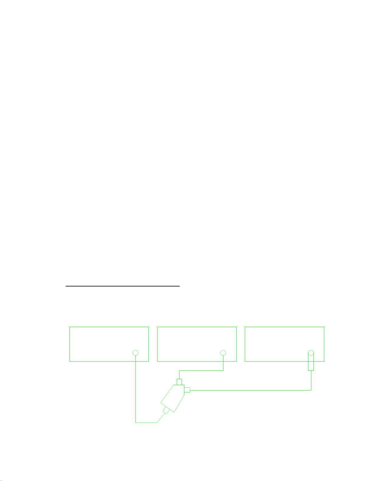
4.7.1 Connect Equipment as shown in Figure 1.
PRECISION ATTENUATION
SYNTHESIZED SWEEPER MEASUREMENT RECEIVER
OUTPUT
.01-18 RF
TI
20 dB
ATTENUATO
POWER
SPLITTER
Figure 1.
9
Page 12

T.O. 33K3-4-2400-1
4.7.2 Use UTIL MENU #2 (keypad entries) to set TI controls as follows:
FREQUENCY 100 MHz
REFERENCE LEVEL -30 dBm
FREQ SPAN/DIV 10 kHz
RESOLUTION BW 3 kHz
VIDEO FILTER ON
VERTICAL SCALE 10 dB/DIV
RF ATTENUATION 0 dB
4.7.3 Press TI DSPL MENU #4 for Peak Acquisition Mode.
4.7.4 Set Synthesized Signal Generator for a 100 MHz CW signal and adjust output amplitude for a full scale
indication on TI display.
4.7.5 Detect and capture the signal on the Precision Attenuation Measurement Receiver (1295).
4.7.6 Press 1295 LEVEL, STORE and DIFFERENCE pushbuttons and ensure 1295 Display indicates 00 ±0.02
dB.
4.7.7 Slowly reduce the output amplitude of the Synthesized Signal Generator until the TI display decreases one
full division.
4.7.8 The 1295 display must indicate -10.0 ±1.0 dB.
4.7.9 Repeat step 4.7.7 for each division on TI display. The 1295 indication must decrease 10 dB
±1.0 dB for each division not to exceed ±2.0 dB over the 0 to 70 dB range and 10 dB ±2.0 dB from 70 to 80 dB.
4.7.10 Slowly set output amplitude of the Synthesized Signal Generator for a full scale deflection on TI display.
4.7.11 Set TI VERTICAL SCALE to 5 dB/DIV, if necessary repeat step 4.7.10.
4.7.12 Repeat step 4.7.6.
4.7.13 Slowly reduce the output amplitude of the Synthesized Signal Generator until the TI display decreases one
full division.
4.7.14 The 1295 display must indicate -5.0 ±1.0 dB.
4.7.15 Repeat step 4.7.13 for each division on TI display. The 1295 indication must decrease 5 dB
±1.0 dB for each division not to exceed ±2.0 dB over the entire 40 dB of dynamic range.
4.7.16 Slowly set output amplitude of the Synthesized Signal Generator for a full scale deflection on TI display.
4.7.17 Set TI VERTICAL SCALE to 1 dB/DIV, if necessary repeat step 4.7.10.
4.7.18 Repeat step 4.7.6.
10
Page 13

T.O. 33K3-4-2400-1
4.7.19 Slowly reduce the output amplitude of the Synthesized Signal Generator until the TI display decreases one
full division.
4.7.20 The 1295 display must indicate -1.0 ±1.0 dB.
4.7.21 Repeat step 4.7.19 for each division on TI display. The 1295 indication must decrease 1 dB
±1.0 dB for each division not to exceed ±1.0 dB over the entire 8.0 dB of dynamic range.
4.7.22 Set TI VERTICAL SCALE to LIN and if necessary adjust the output amplitude of the Synthesized Signal
Generator for a full scale deflection on TI display.
4.7.23 Press 1295 LEVEL, STORE and DIFFERENCE pushbuttons and ensure 1295 Display indicates 00 ±0.02
dB.
4.7.24 Slowly decrease the output of the Synthesized Signal Generator until the 1295 display indicates
-6 dB.
4.7.25 The signal must decrease 4 divisions ±2.0 minor divisions on the TI display.
4.7.26 Slowly decrease the output of the Synthesized Signal Generator until the 1295 display indicates -12 dB.
4.7.27 The signal must decrease 2 more divisions (6 divisions total) ±2.0 minor divisions on the TI display.
4.7.28 Disconnect the test setup.
4.8 AVERAGE NOISE LEVEL CALIBRATION:
4.8.1 Set TI controls as follows:
PREAMP OFF (Press INPUT MENU, #1)
FREQUENCY 25 MHz
REFERENCE LEVEL -40 dBm
FREQ SPAN/DIV 5 MHz
RESOLUTION BW 30 kHz
ACQUISITION MODE PEAK (Press DSPL MENU, #4)
VERTICAL SCALE 10 dB/DIV
4.8.2 Press TI UTIL MENU #2 (keypad settings), #5 (Video Filter), #1 (fixed) and enter 3 kHz to select the 3 kHz
Video Filter.
4.8.3 All noise and spurious signals on TI display must not have an amplitude greater than -100 dBm
(-0 dB or 6th graticule line down from the top).
4.8.4 Adjust TI FREQUENCY from 25 to 1775 MHz in 50 MHz increments, at each increment verify that all
noise and spurious signals are less than -100 dBm.
4.8.5 Connect the Synthesized Signal Generator set to 100 MHz at -0 dBm through a Low Pass Filter to the TI RF
INPUT.
11
Page 14

T.O. 33K3-4-2400-1
4.8.6 Set TI controls as follows:
FREQUENCY 100 MHz
REFERENCE LEVEL -0 dBm
FREQ SPAN/DIV 100 kHz
RESOLUTION BW 30 kHz
VIDEO FILTER ON (AUTO)
VERTICAL SCALE 10 dB/DIV
4.8.7 If necessary adjust the Synthesized Signal Generator amplitude for a reference at the top TI graticule line.
4.8.8 Set TI FREQUENCY to 200 MHz.
4.8.9 The response as shown on TI display must be at least 66 dB (6.6 divisions) down from the reference
established in step 4.8.7.
4.9 NOISE SIDEBAND CALIBRATION:
4.9.1 Press TI INPUT MENU #9 and set TI controls as follows:
FREQUENCY 100 MHz
REFERENCE LEVEL -30 dBm
SPAN DIV 50 kHz
RESOLUTION BW 3 kHz
VIDEO FILTER ON
VERTICAL SCALE 10 dB/DIV
SWEEP AUTO
4.9.2 Enable TI Peak Detection by pressing DSPL MENU #4.
4.9.3 Check that the Noise Sidebands are at 70 dB or more down from peak amplitude 90 kHz away from the TI
Center Frequency.
4.9.4 Set TI RESOLUTION BW to 30 kHz and SPAN/DIV to 500 kHz.
4.9.5 Check that the Noise Sidebands are at 70 dB or more down from peak amplitude 900 kHz away from the TI
Center Frequency.
12 Change 1
NOTE
For Opt 01 TI (300 Hz Resolution BW) do steps 4.9.6 and 4.9.7 before
proceeding with step 4.9.8 for all other TI Options continue with calibration at
step 4.9.8.
Page 15

T.O. 33K3-4-2400-1
4.9.6 Set TI RESOLUTION BW to 300 Hz and SPAN/DIV to 5 kHz.
4.9.7 Check that the Noise Sidebands are at 70 dB or more down from peak amplitude 9 kHz away from the TI
Center Frequency.
4.9.8 Turn TI Calibrator OFF by pressing INPUT MENU #9.
4.9.9 Set TI controls as follows:
FREQUENCY 100 MHz
REFERENCE LEVEL -30 dBm
SPAN DIV 10 MHz
RESOLUTION BW *(300 kHz or 500 kHz)
VIDEO FILTER ON
VERTICAL SCALE 10 dB/DIV
SWEEP AUTO
*(300 kHz filter replaced by 500 kHz filter in TI with S/N B010001 to B010318)
4.9.10 Connect a 100 MHz signal from the Synthesized Signal Generator through the Step Attenuator set for 30
dB to the TI RF INPUT.
4.9.11 Set Synthesized Signal Generator amplitude (approximately 0 dBm) for a full scale signal (top graticule
line) on TI display.
4.9.12 Set Step Attenuator to 0 dB.
4.9.13 Check that the noise sidebands are at least 70 dB down (40 dB down from TI top graticule line) 15 MHz
(1.5 divisions) away from TI Center Frequency.
4.9.14 Set TI RESOLUTION BW to 5 MHz and FREQ SPAN/DIV to 50 MHz. Set Step Attenuator
to 30 dB.
4.9.15 Set Synthesized Signal Generator amplitude (approximately 0 dBm) for a full scale signal (top graticule
line) on TI display.
4.9.16 Set Step Attenuator to 0 dB.
4.9.17 Check that the noise sidebands are at least 70 dB down (40 dB down from TI top graticule line) 150 MHz
away from TI Center Frequency.
4.9.18 Set all Outputs to OFF or Zero, disconnect and secure all equipment.
CALIBRATION PERFORMANCE TABLE
Not Required
Change 2 13/(14 Blank)
 Loading...