

Page 1

Instruction Manual
2706
RF Preselector
070-8545-02
Warning
The servicing instructions are for use by qualified
personnel only. To avoid personal injury, do not
perform any servicing unless you are qualified to
do so. Refer to all safety summaries prior to
performing service.
www.tektronix.com
Page 2

Copyright © T ektronix, Inc. All rights reserved.
T ektronix products are covered by U.S. and foreign patents, issued and pending. Information in this publication supercedes
that in all previously published material. Specifications and price change privileges reserved.
T ektronix, Inc., P.O. Box 500, Beaverton, OR 97077
TEKTRONIX and TEK are registered trademarks of T ektronix, Inc.
Page 3

WARRANTY
T ektronix warrants that this product will be free from defects in materials and workmanship for a period of one (1)
year from the date of shipment. If any such product proves defective during this warranty period, T ektronix, at its
option, either will repair the defective product without charge for parts and labor, or will provide a replacement in
exchange for the defective product.
In order to obtain service under this warranty, Customer must notify Tektronix of the defect before the expiration
of the warranty period and make suitable arrangements for the performance of service. Customer shall be
responsible for packaging and shipping the defective product to the service center designated by T ektronix, with
shipping charges prepaid. Tektronix shall pay for the return of the product to Customer if the shipment is to a
location within the country in which the T ektronix service center is located. Customer shall be responsible for
paying all shipping charges, duties, taxes, and any other charges for products returned to any other locations.
This warranty shall not apply to any defect, failure or damage caused by improper use or improper or inadequate
maintenance and care. T ektronix shall not be obligated to furnish service under this warranty a) to repair damage
resulting from attempts by personnel other than T ektronix representatives to install, repair or service the product;
b) to repair damage resulting from improper use or connection to incompatible equipment; or c) to service a
product that has been modified or integrated with other products when the effect of such modification or
integration increases the time or difficulty of servicing the product.
THIS WARRANTY IS GIVEN BY TEKTRONIX WITH RESPECT TO THIS PRODUCT IN LIEU OF
ANY OTHER WARRANTIES, EXPRESSED OR IMPLIED. TEKTRONIX AND ITS VENDORS
DISCLAIM ANY IMPLIED WARRANTIES OF MERCHANTABILITY OR FITNESS FOR A
P ARTICULAR PURPOSE. TEKTRONIX’ RESPONSIBILITY TO REPAIR OR REPLACE DEFECTIVE
PRODUCTS IS THE SOLE AND EXCLUSIVE REMEDY PROVIDED TO THE CUSTOMER FOR
BREACH OF THIS WARRANTY. TEKTRONIX AND ITS VENDORS WILL NOT BE LIABLE FOR ANY
INDIRECT, SPECIAL, INCIDENTAL, OR CONSEQUENTIAL DAMAGES IRRESPECTIVE OF
WHETHER TEKTRONIX OR THE VENDOR HAS ADVANCE NOTICE OF THE POSSIBILITY OF
SUCH DAMAGES.
Page 4

Contents
User Information
List of Figures ii. . . . . . . . . . . . . . . . . . . . . . . . . . . . . . . . . . . . . . . . . . . . .
List of Tables ii. . . . . . . . . . . . . . . . . . . . . . . . . . . . . . . . . . . . . . . . . . . . . .
Preface iii. . . . . . . . . . . . . . . . . . . . . . . . . . . . . . . . . . . . . . . . . . . . . . . . . . .
Welcome iii. . . . . . . . . . . . . . . . . . . . . . . . . . . . . . . . . . . . . . . . . . . . . . . . . . . . . . . .
About this Manual iii. . . . . . . . . . . . . . . . . . . . . . . . . . . . . . . . . . . . . . . . . . . . . . . .
What you Need to Know iv. . . . . . . . . . . . . . . . . . . . . . . . . . . . . . . . . . . . . . . . . . .
How to Use This Manual iv. . . . . . . . . . . . . . . . . . . . . . . . . . . . . . . . . . . . . . . . . . .
Manual Conventions v. . . . . . . . . . . . . . . . . . . . . . . . . . . . . . . . . . . . . . . . . . . . . .
Contacting T ektronix v. . . . . . . . . . . . . . . . . . . . . . . . . . . . . . . . . . . . . . . . . . . . . .
General Safety Summary vii. . . . . . . . . . . . . . . . . . . . . . . . . . . . . . . . . . . .
Service Safety Summary ix. . . . . . . . . . . . . . . . . . . . . . . . . . . . . . . . . . . . .
Introduction 1–1. . . . . . . . . . . . . . . . . . . . . . . . . . . . . . . . . . . . . . . . . . . . . . .
Preselector Controls and Connectors 1–1. . . . . . . . . . . . . . . . . . . . . . . . . . . . . . . . . .
What you Need to Use the Preselector 1–2. . . . . . . . . . . . . . . . . . . . . . . . . . . . . . . . .
Using the Preselector 2–1. . . . . . . . . . . . . . . . . . . . . . . . . . . . . . . . . . . . . . . .
Manual Operation 2–1. . . . . . . . . . . . . . . . . . . . . . . . . . . . . . . . . . . . . . . . . . . . . . . . .
Remote Operation 2–1. . . . . . . . . . . . . . . . . . . . . . . . . . . . . . . . . . . . . . . . . . . . . . . .
GPIB Common and Device Commands 2–3. . . . . . . . . . . . . . . . . . . . . . . . . . . . . . .
Service Information
Appendixes
Performance Verification 3–1. . . . . . . . . . . . . . . . . . . . . . . . . . . . . . . . . . . .
Performance Verification Procedure 3–1. . . . . . . . . . . . . . . . . . . . . . . . . . . . . . . . . .
Troubleshooting 3–2. . . . . . . . . . . . . . . . . . . . . . . . . . . . . . . . . . . . . . . . . . . . . . . . . .
Replacing the Fuse 3–3. . . . . . . . . . . . . . . . . . . . . . . . . . . . . . . . . . . . . . . . . . . . . . . .
Applications 4–1. . . . . . . . . . . . . . . . . . . . . . . . . . . . . . . . . . . . . . . . . . . . . . .
EMI Testing 4–1. . . . . . . . . . . . . . . . . . . . . . . . . . . . . . . . . . . . . . . . . . . . . . . . . . . . .
Susceptibility T esting 4–2. . . . . . . . . . . . . . . . . . . . . . . . . . . . . . . . . . . . . . . . . . . . . .
Benchtop Analysis 4–2. . . . . . . . . . . . . . . . . . . . . . . . . . . . . . . . . . . . . . . . . . . . . . . .
Appendix A: Specifications A–1. . . . . . . . . . . . . . . . . . . . . . . . . . . . . . . . . . .
Electrical Specifications A–1. . . . . . . . . . . . . . . . . . . . . . . . . . . . . . . . . . . . . . . . . . . .
Mechanical Specifications A–2. . . . . . . . . . . . . . . . . . . . . . . . . . . . . . . . . . . . . . . . . .
Environmental Specifications A–2. . . . . . . . . . . . . . . . . . . . . . . . . . . . . . . . . . . . . . .
Certifications and Compliances A–3. . . . . . . . . . . . . . . . . . . . . . . . . . . . . . . . . . . . . .
Appendix B: Using the GPIB Interface B–1. . . . . . . . . . . . . . . . . . . . . . . . .
Interface Compatibility B–1. . . . . . . . . . . . . . . . . . . . . . . . . . . . . . . . . . . . . . . . . . . .
Controller Commands B–2. . . . . . . . . . . . . . . . . . . . . . . . . . . . . . . . . . . . . . . . . . . . .
Sample Program B–3. . . . . . . . . . . . . . . . . . . . . . . . . . . . . . . . . . . . . . . . . . . . . . . . . .
GPIB Commands B–5. . . . . . . . . . . . . . . . . . . . . . . . . . . . . . . . . . . . . . . . . . . . . . . . .
2706 RF Preselector
i
Page 5

Contents
List of Figures
Appendix C: Options C–1. . . . . . . . . . . . . . . . . . . . . . . . . . . . . . . . . . . . . . . .
Power Cord Options C–1. . . . . . . . . . . . . . . . . . . . . . . . . . . . . . . . . . . . . . . . . . . . . . .
Option 01 C–1. . . . . . . . . . . . . . . . . . . . . . . . . . . . . . . . . . . . . . . . . . . . . . . . . . . . . . .
Appendix D: Parts List D–1. . . . . . . . . . . . . . . . . . . . . . . . . . . . . . . . . . . . . .
Standard Accessories D–1. . . . . . . . . . . . . . . . . . . . . . . . . . . . . . . . . . . . . . . . . . . . . .
Options D–1. . . . . . . . . . . . . . . . . . . . . . . . . . . . . . . . . . . . . . . . . . . . . . . . . . . . . . . . .
Appendix E: Repackaging for Shipment E–1. . . . . . . . . . . . . . . . . . . . . . . .
Figure 1–1: The Preselector’s Front Panel 1–1. . . . . . . . . . . . . . . . . . . . . .
Figure 1–2: The Preselector’s Rear Panel 1–2. . . . . . . . . . . . . . . . . . . . . . .
Figure 3–1: The fuse location 3–4. . . . . . . . . . . . . . . . . . . . . . . . . . . . . . . . .
List of Tables
Table 2–1: Commands Supported by the Preselector 2–3. . . . . . . . . . . . .
Table A–1: Preselector Band Related Specifications A–1. . . . . . . . . . . . . .
Table A–2: Certifications and compliances A–3. . . . . . . . . . . . . . . . . . . . .
ii
2706 RF Preselector
Page 6

Preface
Welcome
This preface describes the features of the Tektronix 2706 stepped Radio
Frequency Preselector. It also tells you how to use this manual and what you
should know before you use the Preselector.
Congratulations on your purchase of a 2706 RF Preselector. This instrument
improves the flexibility and accuracy of your spectrum analyzer measurements,
and is especially useful for EMI applications.
Some of the outstanding characteristics of the Preselector are:
H Multiple filters – the Preselector has 7 bandpass filter steps covering the
range from 9 kHz to 1000 MHz, and a high-pass filter covering the range
from 1000 MHz to 1800 MHz.
H Reduced distortion – the Preselector limits potentially distorting input to a
spectrum analyzer by attenuating signals outside the frequency range of
interest.
About this Manual
H Increased broadband dynamic range – the Preselector increases sensitivity to
low-level signals by attenuating strong signals outside the frequency range of
interest.
H Manual or remote operation – you can operate the Preselector using its
front-panel controls or a GPIB equipped controller or computer.
H Bypass mode – you can remove the Preselector from the testing circuit
without disconnecting it.
H Convenient installation – the Preselector mounts below Tektronix 271X-
Series Spectrum Analyzers with the optional mounting plate and rigid
coaxial cable assembly (see the Parts List in Appendix D).
This manual contains the following sections:
H Chapter 1, “Introduction,” lists the features of the Tektronix 2706 RF
Preselector and what you need to use the Preselector.
H Chapter 2, “Using the Preselector,” describes how to control the Preselector
manually or using a GPIB controller.
2706 RF Preselector
iii
Page 7

Preface
H Chapter 3, “Performance Verification,” tells you how to check that the
Preselector is operating within specification, and how to troubleshoot
problems with the Preselector.
H Chapter 4, “Applications,” describes ways you can use the Preselector.
H Appendix A, “Specifications,” lists the electrical, environmental, and
mechanical specifications of the Preselector.
H Appendix B, “Using the GPIB Interface,” describes in detail the commands
you use to operate the Preselector remotely.
H Appendix C, “Options,” describes in detail the power cord and extended
service options of the Preselector.
H Appendix D, “Parts List,” lists the part numbers of the standard and optional
Preselector accessories.
H Appendix E, “Repackaging for Shipment,” describes how to package the
Preselector for shipment.
What you Need to Know
How to Use This Manual
To use this manual, you need to know two things:
H How to operate a spectrum analyzer.
H The basic concepts of signal analysis.
If you plan to operate the Preselector remotely, you also need to know how to
use your GPIB controller.
This manual is designed to help you learn to use the Preselector quickly and
easily.
Follow these steps to use this manual:
1. Read the rest of this preface.
2. Read Chapter 1, “Introduction,” for an overview of the Preselector’s features.
3. Follow the instructions in Chapter 2, “Using the Preselector,” to learn how to
use the Preselector.
4. Use Chapter 3, “Performance Verification,” and Appendix A, “Specifica-
tions,” to check that the Preselector is working correctly.
iv
2706 RF Preselector
Page 8

Manual Conventions
Contacting Tektronix
Preface
5. Use Chapter 4, “Applications,” to see ways you can use the Preselector.
6. If you plan to operate the Preselector from a GPIB controller, use Appendix
B, “Using the GPIB Interface.”
To make this manual easier to use, text is shown in several type styles:
H References to other manuals or documents are in italics: ANSI/IEEE Std
488.2–1987.
H Command names, and panel and cable labels are in bold type.
H Text that you type into a GPIB controller is in single space type.
Product
Support
Service
support
Toll-free
Number
Postal
Address
Web site www.tektronix.com
For questions about using Tektronix measurement products, call
toll free in North America:
1-800-833-9200
6:00 a.m. – 5:00 p.m. Pacific time
Or contact us by e-mail:
tm_app_supp@tek.com
For product support outside of North America, contact your
local Tektronix distributor or sales office.
Tektronix offers a range of services, including Extended
Warranty Repair and Calibration services. Contact your local
Tektronix distributor or sales office for details.
For a listing of worldwide service centers, visit our web site.
In North America:
1-800-833-9200
An operator can direct your call.
Tektronix, Inc.
Department or name (if known)
P.O. Box 500
Beaverton, OR 97077
USA
2706 RF Preselector
v
Page 9

Preface
vi
2706 RF Preselector
Page 10

General Safety Summary
Review the following safety precautions to avoid injury and prevent damage to
this product or any products connected to it. To avoid potential hazards, use this
product only as specified.
Only qualified personnel should perform service procedures.
While using this product, you may need to access other parts of the system. Read
the General Safety Summary in other system manuals for warnings and cautions
related to operating the system.
To Avoid Fire or Personal Injury
Use Proper Power Cord. Use only the power cord specified for this product and
certified for the country of use.
Connect and Disconnect Properly . Do not connect or disconnect probes or test
leads while they are connected to a voltage source.
Ground the Product. This product is grounded through the grounding conductor
of the power cord. To avoid electric shock, the grounding conductor must be
connected to earth ground. Before making connections to the input or output
terminals of the product, ensure that the product is properly grounded.
Observe All Terminal Ratings. To avoid fire or shock hazard, observe all ratings
and markings on the product. Consult the product manual for further ratings
information before making connections to the product.
Connect the ground lead of the probe to earth ground only.
Do not apply a potential to any terminal, including the common terminal, that
exceeds the maximum rating of that terminal.
Do Not Operate Without Covers. Do not operate this product with covers or panels
removed.
Use Proper Fuse. Use only the fuse type and rating specified for this product.
Avoid Exposed Circuitry. Do not touch exposed connections and components
when power is present.
2706 RF Preselector
Do Not Operate With Suspected Failures. If you suspect there is damage to this
product, have it inspected by qualified service personnel.
Do Not Operate in Wet/Damp Conditions.
Do Not Operate in an Explosive Atmosphere.
Keep Product Surfaces Clean and Dry .
Provide Proper Ventilation. Refer to the manual’s installation instructions for
details on installing the product so it has proper ventilation.
vii
Page 11

General Safety Summary
Symbols and Terms
T erms in this Manual. These terms may appear in this manual:
WARNING. Warning statements identify conditions or practices that could result
in injury or loss of life.
CAUTION. Caution statements identify conditions or practices that could result in
damage to this product or other property.
T erms on the Product. These terms may appear on the product:
DANGER indicates an injury hazard immediately accessible as you read the
marking.
WARNING indicates an injury hazard not immediately accessible as you read the
marking.
CAUTION indicates a hazard to property including the product.
Symbols on the Product. The following symbols may appear on the product:
CAUTION
Refer to Manual
WARNING
High Voltage
Double
Insulated
Protective Ground
(Earth) Terminal
Not suitable for
connection to
the public telecom-
munications network
viii
2706 RF Preselector
Page 12

Service Safety Summary
Only qualified personnel should perform service procedures. Read this Service
Safety Summary and the General Safety Summary before performing any service
procedures.
Do Not Service Alone. Do not perform internal service or adjustments of this
product unless another person capable of rendering first aid and resuscitation is
present.
Disconnect Power. To avoid electric shock, switch off the instrument power, then
disconnect the power cord from the mains power.
Use Care When Servicing With Power On. Dangerous voltages or currents may
exist in this product. Disconnect power, remove battery (if applicable), and
disconnect test leads before removing protective panels, soldering, or replacing
components.
To avoid electric shock, do not touch exposed connections.
2706 RF Preselector
ix
Page 13

Service Safety Summary
x
2706 RF Preselector
Page 14

User Information
Page 15
Introduction
This chapter describes the features of the Tektronix 2706 RF Preselector and
what you need to use it.
Preselector Controls and Connectors
This section presents a brief tour of the Preselector controls and connectors.
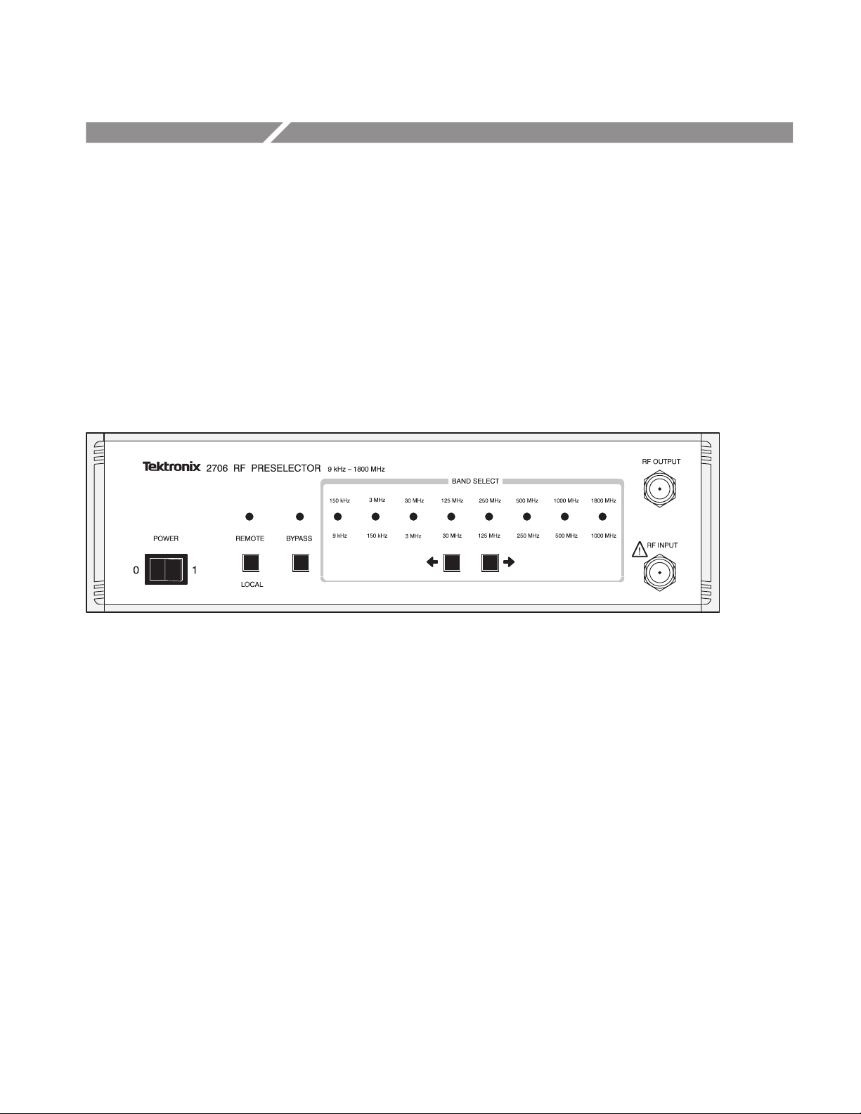
Front Panel
Figure 1–1: The Preselector’s Front Panel
The Preselector front panel has the following controls:
H POWER switch – this turns instrument operating power on (1) or off (0).
H REMOTE/LOCAL switch – this transfers control of the Preselector from
remote (GPIB controlled) mode to local (manually controlled) mode. The
REMOTE LED lights when remote mode is selected.
H BYPASS switch – this disconnects all Preselector filters so that the entire RF
signal is sent directly to the spectrum analyzer. The BYPASS LED lights
when bypass mode is selected.
2706 RF Preselector
H BAND SELECT <- and -> switches – these select the signal routing band from
among 7 bandpass filters and a high-pass filter. An LED lights on the front
panel to indicate the selected filter.
H RF INPUT – this connects the Preselector to the signal source using a type N
plug.
H RF OUTPUT – this connects the preselected output to the spectrum analyzer
using a type N plug.
1–1
Page 16

Introduction
Rear Panel
Figure 1–2: The Preselector’s Rear Panel
The Preselector rear panel has these connectors and switches:
H IEEE STD 488 PORT – this connects the Preselector to a controller.
H ADDRESS switch – this selects the GPIB address for the Preselector.
H POWER – this plugs the Preselector into the AC power source
(90–250 VAC, 48–63 Hz).
What you Need to Use the Preselector
To use the Preselector, you need the following:
H an RF signal source, such as an antenna or test device (Chapter 4, “Applica-
tions,” describes example setups)
H a spectrum analyzer, such as the Tektronix 271X–, 278X–, or 279X–Series
(or equivalent)
H two RF connecting cables with type N connectors or adapters
If you will operate the Preselector remotely, you will also need the following:
H an IEEE STD 488 GPIB 24-pin cable with a D-type shell (Tektronix part
number 012–0991–00)
H an IEEE–488 GPIB controller, or an IBM PC/AT or compatible 80386 (or
better) personal computer with a National Instruments PCII/IIA type card
and communications drivers
H a copy of the Tektronix S26EM12 Commercial EMI Test Software (optional)
1–2
2706 RF Preselector
Page 17

Using the Preselector
This chapter describes how to operate the Preselector manually or with a GPIB
controller.
Manual Operation
This section tells you how to use the Preselector manually by using its front-panel controls.
Use the Preselector as follows:
1. Plug the Preselector into a power source (90–250 VAC, 48–63 Hz).
2. Connect the spectrum analyzer input to the RF OUTPUT connector on the
Preselector’s front panel.
3. Turn on the Preselector. The front-panel LEDs will light sequentially. When
the BYPASS LED lights, the unit is ready to use.
NOTE. If any of the LEDs do not light, refer to Chapter 3, Performance
Verification.
Remote Operation
4. Turn on the spectrum analyzer.
5. Use the BAND SELECT <- and -> switches to select the filter you want. The
Preselector will pass the frequency range printed above and below the lit
LED.
6. Connect the RF source to the RF INPUT connector on the Preselector’s front
panel.
The Preselector is now ready for operation.
This section tells you how to operate the Preselector remotely with a controller
or computer that uses the IEEE Standard 488.2-1987 (GPIB) interface.
The smallest GPIB network that you can use is a Preselector and a controller;
you will also probably connect a spectrum analyzer to the network.
2706 RF Preselector
2–1
Page 18

Using the Preselector
NOTE. To operate the Preselector remotely, you need to consult the documentation for your controller to determine how to send commands and interpret
received messages in your controller’s programming language.
Use the Preselector remotely as follows:
1. Plug the Preselector into a power source (90–250 VAC, 48–63 Hz).
2. Connect the spectrum analyzer input to the RF OUTPUT connector on the
Preselector’s front panel.
3. Connect a GPIB 24-pin cable to the IEEE STD 488 PORT connector on the
rear panel of your Preselector and to the GPIB network.
4. Verify that the bus address on the rear-panel ADDRESS switch is not used by
any other device on the network. If the address is used by another device, use
the switch to select a new address. The Preselector will use the new address
when it is turned on.
5. To make sure that your GPIB network will operate reliably, verify that:
H Each device on the network has a unique device address.
H The network has fewer than 16 devices.
H No more than 2 meters (6 feet) of cable separates any two devices, and
that the entire network uses less than 20 meters (65 feet) of GPIB cable.
H At least two-thirds of the devices on the network are turned on when the
network is operating.
H The network uses a star or linear configuration, not a loop or parallel
configuration.
6. Turn on the Preselector. The front-panel LEDs will light sequentially. When
the BYPASS LED lights, the unit is ready to use.
NOTE. If the LEDs do not light, refer to Chapter 3, Performance Verification.
Pressing the REMOTE/LOCAL switch will not turn on remote operation; it only
turns remote operation off.
7. Turn on the spectrum analyzer.
8. Turn on the controller and start the GPIB communications software.
2–2
9. Connect the RF source to the RF INPUT connector on the Preselector’s front
panel.
2706 RF Preselector
Page 19

The Preselector is now ready for remote operation. You can operate it by using a
controller to send commands described in the following GPIB Common and
Device Commands section.
Refer to Appendix B, Using the GPIB Interface, and your controller’s operating
manual for detailed information about sending GPIB commands.
GPIB Common and Device Commands
This section briefly lists the common and device commands used to operate the
Preselector from a remote GPIB controller. Appendix B, Using the GPIB
Interface, contains a detailed, alphabetical listing of these commands and
provides an example program.
Common commands (preceded by an asterisk in Table 2.1) are used by all
devices that meet IEEE Std. 488.2-1987. Device commands (listed without an
asterisk in Table 2.1) are specific to the Preselector and are defined only in this
manual. The Preselector has two device commands: B and STS?.
Using the Preselector
NOTE. You do not need to use timing commands such as *WAI, *OPC, and
*OPC? with the Preselector. For example, the *WAI command normally prevents
a GPIB device from executing commands until all pending operations finish.
Because the Preselector executes commands sequentially, the *WAI command
always continues immediately.
T able 2–1: Commands Supported by the Preselector
Name
B<NR1> Select band filter (NR1 stands for an integer from 0 to 8)
*CLS Clear Status
*ESE and *ESE? Standard Event Status Enable
*ESR? Standard Event Status Register Query
*IDN? Identification Query
*IST? Individual Status Query
*OPC and *OPC? Operation Complete
*PRE and *PRE? Parallel Poll Register Enable
*RST Reset
*SRE and *SRE? Service Request Enable
Full Command Title
2706 RF Preselector
*STB? Read Status Byte
STS? Status Selected Band Query
2–3
Page 20

Using the Preselector
T able 2–1: Commands Supported by the Preselector (Cont.)
Name
*TST? Self-Test
*WAI Wait To Continue
Full Command Title
2–4
2706 RF Preselector
Page 21

WARNING
The following servicing instructions are for use only by qualified personnel. To
avoid injury, do not perform any servicing other than that stated in the operating
instructions unless you are qualified to do so. Refer to all safety summaries before
performing any service.
Page 22

Service Information
Page 23

Performance Verification
This chapter describes how to check that the Preselector is operating within
specification and how to troubleshoot simple problems the Preselector may have.
Performance V erification Procedure
To verify that your Preselector is operating within specification, you need:
H a spectrum analyzer with a tracking generator, such as the Tektronix 2712 (or
equivalent)
H two RF connecting cables with type N connectors or adapters
Test the Preselector as follows:
1. Plug the Preselector into a power source (90–250 VAC, 48–63 Hz).
2. Connect the spectrum analyzer input to the RF OUTPUT connector on the
Preselector’s front panel.
3. Connect the spectrum analyzer’s tracking generator output to the RF INPUT
connector on the Preselector’s front panel.
4. Turn on the Preselector. The front-panel LEDs will light sequentially. When
the BYPASS LED lights, the unit is ready to use.
NOTE. If any of the LEDs do not light, refer to the troubleshooting section that
follows this procedure.
5. Turn on the spectrum analyzer.
6. Set the spectrum analyzer controls as follows:
Reference level = –10 dBm
Vertical scale = 5 dB/div
Tracking generator = On
Tracking generator output level = –20 dBm
7. Select Frequency Start/Stop from the spectrum analyzer’s Mkr/Freq Menu.
8. Leave the start frequency at the 0 Hz default value.
2706 RF Preselector
3–1
Page 24

Performance Verification
9. Enter the stop frequency from the table below.
Preselector band Stop frequency
9 kHz – 150 kHz
150 kHz – 3 MHz 10 MHz
3 MHz – 30 MHz 50 MHz
30 MHz – 125 MHz 300 MHz
125 MHz – 250 MHz 300 MHz
250 MHz – 500 MHz 1.8 GHz
500 MHz – 1 GHz 1.8 GHz
1 GHz – 1.8 GHz 1.8 GHz
400 kHz
10. Use the Preselector BYPASS switch to select bypass mode.
11. Verify that the tracking generator reference trace is at –20 dBm. The flat
output signal from the tracking generator should be one major division
below the top of the display.
Troubleshooting
Use the Demod/TG Menu to adjust the tracking generator if necessary in the
lower bands.
12. Store the display in register A.
13. Use the BAND SELECT <- and -> switches to select the filter corresponding
to the stop frequency you selected.
14. Read the frequency response and insertion loss from the spectrum analyzer’s
screen. If the values exceed those in Appendix A, Specifications, ship the
Preselector to your nearest Tektronix service center (follow the Repackaging
for Shipment Instructions in Appendix E).
15. Repeat steps 7 to 14 for each of the Preselector’s bands.
The Preselector has now passed its performance test.
Follow these instructions if the Preselector does not turn on or select RF bands
correctly:
1. Check that all cables are connected correctly to the Preselector.
3–2
2. Check that power is available.
2706 RF Preselector
Page 25

Replacing the Fuse
Performance Verification
3. Turn on the Preselector. If the Preselector does not turn on, have qualified
personnel replace the fuse as described in “Replacing the fuse,” later in this
section.
4. All the LEDs should light at least once during the power-on test. If some of
the LEDs do not light, or the Preselector does not finish its test with the
BYPASS LED lit, or the Preselector does not otherwise work correctly, ship it
to your nearest Tektronix service center (follow the Repackaging for
Shipment Instructions in Appendix E).
The fuse is located on the power supply board inside the Preselector. This
procedure assumes that the rear panel of the Preselector is closest to you.
Replace the fuse as follows:
WARNING. To avoid injury, unplug the Preselector before replacing the fuse.
1. Disconnect the Preselector power cord.
2. Remove the two upper screws on the rear panel that hold the top panel to the
Preselector cabinet.
3. Firmly grip the top cover and slide it toward the rear of the cabinet.
4. Find fuse holder F1 on the power supply, as shown in Figure 3.1.
2706 RF Preselector
3–3
Page 26

Performance Verification
Figure 3–1: The fuse location
5. Using needle-nose pliers, gently pull out the fuse.
CAUTION. To avoid the risk of fire, replace a damaged fuse only with a fuse of
the specified type and rating.
6. Replace the fuse with a 250 VAC 2 A model 3AG Med-Blo fuse.
7. Seat all ribbon cables by pressing firmly on all the connectors.
8. Slide the top panel back onto the cabinet.
9. Replace the two screws on the rear panel.
10. Plug the Preselector back in.
The Preselector is now ready for use.
3–4
2706 RF Preselector
Page 27

Applications
EMI Testing
This chapter briefly describes several applications that can benefit from using the
Preselector.
These include:
H Electromagnetic interference (EMI) testing
H Susceptibility testing
H Benchtop analysis
In each case, you can use the Preselector manually or remotely (with a controller
connected to the IEEE-488 GPIB interface).
The Preselector can increase the accuracy of your EMI compliance tests for
standards such as:
H FCC regulations (USA)
Measuring Conducted EMI
Emissions
H CENELEC regulations (EC)
H VDE regulations (Germany)
H CISPR (International)
H VCCI standards (Japan)
H MIL-STD-461/462
The Preselector can help your spectrum analyzer measure EMI conducted out of
a device by attenuating strong signals outside the band of interest.
Use a Line Impedance Stabilization Network (LISN) for conducted emissions
tests.
CAUTION. To avoid damage to the spectrum analyzer, always use a transient
limiter with the LISN. Connect the transient limiter between the LISN and the
Preselector. The Preselector alone cannot protect the spectrum analyzer from
power surges.
A LISN provides a known source impedance for the connected power line and
provides access to the RF signals of the device under test.
2706 RF Preselector
4–1
Page 28

Applications
Radiated EMI Testing
Susceptibility Testing
The Preselector, with appropriate antennas and other equipment, can help your
spectrum analyzer measure EMI radiated from a particular device. The Preselector attenuates radio and television transmissions and other RF interference
outside the range of interest. Test setups use one of three basic antenna types:
H tuned dipole: used to measure radiated EMI in the 30 MHz to 1000 MHz
range. Different balums and adjustable dipole elements cover the entire
frequency range.
H biconical: used to measure horizontal and vertical polarization of radiated
EMI in the 30 MHz to 300 MHz range. Use a biconical antenna (Tektronix
part number 119–4148–00 or equivalent).
H log periodic: used to measure horizontal and vertical polarization of radiated
EMI in the 200 MHz to 1000 MHz range. Use a log periodic antenna
(Tektronix part number 119–4142–00 or equivalent).
Once you determine the frequency and strength of the radiated EMI, you can
take appropriate corrective action or note the results for specifications.
A spectrum analyzer, with the Preselector, can monitor field strengths during
susceptibility testing.
Benchtop Analysis
CAUTION. To avoid damage to the Preselector and your spectrum analyzer, do
not connect signals higher than +20 dBm or 50 VDC to the Preselector.
The Preselector can improve the frequency response measurement of a circuit or
devices such as cables, mixers, amplifiers, and IF bandwidth chains by passing
only the frequencies you want to the spectrum analyzer. (This is especially useful
if you are using a broad-band noise source.)
4–2
2706 RF Preselector
Page 29

Appendices
Page 30

Appendix A: Specifications
This appendix describes the electrical, mechanical, and environmental specifications of the Tektronix 2706 RF Preselector.
Electrical Specifications
A–1
Filters
T able A–1: Preselector Band Related Specifications
Band Bandpass Nominal loss –6.0 dB bandpass (typical) –40 dB bandpass (typical)
1 9 kHz – 150 kHz 2.0 dB max 6.2 kHz – 220 kHz 3.2 kHz – 440 kHz
2 150 kHz – 3.0 MHz 2.0 dB max 90 kHz – 4.5 MHz 50 kHz – 9.0 MHz
3 3 MHz – 30 MHz 2.0 dB max 2.5 MHZ – 35 MHz 1.6 MHz – 45 MHz
4 30 MHz – 125 MHz 2.0 dB max 23 MHz – 145 MHz 12 MHz – 260 MHz
5 125 MHz – 250 MHz 1.5 dB ±1.0 dB 110 MHz – 280 MHz 100 MHz – 340 MHz
6 250 MHz – 500 MHz 2.0 dB ±1.0 dB 225 MHz – 600 MHz 150 MHz – 950 MHz
7 500 MHz – 1000 MHz 2.0 dB ±1.0 dB 400 MHz – 1 190 MHz 225 MHz – 1400 MHz
8 1000 MHz – 1800 MHz 4.0 dB ±1.0 dB 775 MHz 350 MHz
Range: 9 kHz to 1800 MHz
Insertion loss (max): 2.0 dB
Frequency Range: 9 kHz to 1800 MHz
Bandpass/high-pass flatness: 1.5 dB max
2706 RF Preselector
RF input/output connectors: Type N
Input/output impedance: 50 Ω nominal
VSWR (max): 1.8:1
Ultimate rejection, stop band: 60 dB typical
40 dB min <500 MHz
30 dB min >500 MHz
Maximum input: +20 dBm, 50 VDC
Switching speed (max): 10 ms
A–1
Page 31

Appendix A: Specifications
GPIB interface: Meets IEEE Std. 488.2–1987
GPIB interface supports: AH1, L4, SH1, T6, SR1, PP1,
Input Voltage: 90/250 VAC, 48 – 63 Hz, 10 W
Mechanical Specifications
Dimensions (H x W x D): 88 mm x 327 mm x 431 mm
Weight: 5.9 kg (13 lbs)
Environmental Specifications
Temperature, operating: 0°C to 50°C (32°F to 122°F)
DC1, DT0, RL1,C0, E1, TE0,
and LE0
(3.46 in x 12.87 in x 16.97 in)
Temperature, storage: –40°C to 75°C (–40°F to 167°F)
Humidity, storage: Five cycles (120 hrs) per
MIL–T–28800C, Class 5
Vibration: Meets MIL–T–28800C Method
514 Procedure (modified)
Shock, operating and storage: Three guillotine-type shocks of
30 g, one-half sine, 11 ms duration
each direction along each major
axis; total of 18 shocks
A–2
2706 RF Preselector
Page 32

Certifications and Compliances
T able A–2: Certifications and compliances
Category Standards or description
Appendix A: Specifications
EC Declaration of Conformity –
EMC
FCC Compliance Emissions comply with FCC Code of Federal Regulations 47, Part 15, Subpart B, Class A Limits.
Installation (Overvoltage)
Category
Pollution Degree A measure of the contaminates that could occur in the environment around and within a product.
Meets intent of Directive 89/336/EEC for Electromagnetic Compatibility. Compliance was
demonstrated to the following specifications as listed in the Official Journal of the European Union:
EN 50081-1 Emissions:
EN 55022 Class B Radiated and Conducted Emissions
EN 60555-2 AC Power Line Harmonic Emissions
EN 50082-1 Immunity:
IEC 801-2 Electrostatic Discharge Immunity
IEC 801-3 RF Electromagnetic Field Immunity
IEC 801-4 Electrical Fast Transient/Burst Immunity
High quality shielded cables must be used to ensure compliance to the above listed standards.
Terminals on this product may have different installation (overvoltage) category designations. The
installation categories are:
CA T III Distribution-level mains (usually permanently connected). Equipment at this level is
typically in a fixed industrial location.
CA T II Local-level mains (wall sockets). Equipment at this level includes appliances, portable
tools, and similar products. Equipment is usually cord-connected.
CA T I Secondary (signal level) or battery operated circuits of electronic equipment.
Typically the internal environment inside a product is considered to be the same as the external.
Products should be used only in the environment for which they are rated.
Pollution Degree 1 No pollution or only dry, nonconductive pollution occurs. Products in
this category are generally encapsulated, hermetically sealed, or
located in clean rooms.
Pollution Degree 2
Pollution Degree 3
Pollution Degree 4 Pollution that generates persistent conductivity through conductive
Normally only dry, nonconductive pollution occurs. Occasionally a
temporary conductivity that is caused by condensation must be
expected. This location is a typical office/home environment.
Temporary condensation occurs only when the product is out of
service.
Conductive pollution, or dry, nonconductive pollution that becomes
conductive due to condensation. These are sheltered locations where
neither temperature nor humidity is controlled. The area is protected
from direct sunshine, rain, or direct wind.
dust, rain, or snow. Typical outdoor locations.
2706 RF Preselector
A–3
Page 33

Appendix A: Specifications
T able A–2: Certifications and compliances (cont.)
Category Standards or description
Safety Standards
U.S. Nationally Recognized
Testing Laboratory Listing
Canadian Certification CAN/CSA C22.2 No. 231 CSA safety requirements for electrical and electronic measuring and
European Union Compliance Low Voltage Directive 73/23/EEC, amended by 93/69/EEC
Additional Compliance IEC61010-1 Safety requirements for electrical equipment for measurement,
Safety Certification Compliance
T emperature, operating +5 to +40_ C
Altitude (maximum operating) 2000 meters
Equipment Type Test and measuring
Safety Class Class 1 (as defined in IEC 1010-1, Annex H) – grounded product
Overvoltage Category Overvoltage Category II (as defined in IEC 1010-1, Annex J)
Pollution Degree Pollution Degree 2 (as defined in IEC 1010-1). Note: Rated for indoor use only.
UL1244 Standard for electrical and electronic measuring and test equipment.
test equipment.
EN 61010-1 Safety requirements for electrical equipment for measurement,
control, and laboratory use.
control, and laboratory use.
A–4
2706 RF Preselector
Page 34

Appendix B: Using the GPIB Interface
This appendix describes the GPIB commands that you can use to control the
Preselector.
To run the Preselector automatically from a controller, you can either write your
own software or use commercial software.
Interface Compatibility
GPIB controllers such as the National Instruments PCII/IIA with communications drivers are compatible with the Preselector’s GPIB interface. If you are
building or programming your own interface, refer to the Capability Identification Codes section in the ANSI/IEEE Std 488.2–1987 Handbook for detailed
information about the Preselector’s GPIB capabilities.
The Preselector GPIB interface meets the compatibility requirements of the IEEE
codes listed below. (These codes are also marked below the IEEE STD 488 PORT
on the rear panel.)
Capability Code Meaning
AH1: Acceptor Handshake Capability
L4: Listener (Basic Listener, Unaddressed To Listen On
TAG) Capability
SH1: Source Handshake Capability
T6: Talker (Basic Talker, Serial Poll, Unaddressed To
Talk On LAG) Capability
SR1: Service Request Capability
PP1: Parallel Poll Capability (Remote Configuration)
DC1: Device Clear Capability
DT0: No Device Trigger Capability
RL1: Remote/Local Capability
C0: No Controller Capability
E1: Open Collector Bus Drivers
TE0: No Extended Talker Capabilities
LE0: No Extended Listener Capabilities
2706 RF Preselector
B–1
Page 35

Appendix B: Using the GPIB Interface
Controller Commands
The Preselector accepts the following commands from any GPIB controller.
REMOTE Command
LOCAL LOCKOUT
Command
To put the Preselector into remote mode, you must use your controller’s
REMOTE command to set the GPIB REN line. The specific command you use
to do this will depend on your controller. If you send the REMOTE command as
an addressed command group (UAGC), the Preselector will go into remote mode
immediately.
To use a controller while leaving the Preselector in local mode, do not set the
REN line. The Preselector will then accept commands from the controller but
remain in local mode.
The Preselector lights the front-panel REMOTE LED to indicate that it is in
remote mode.
All Preselector switches, with the exception of the power switch, can be locked
out (made inoperative) by having your controller set the GPIB LOCAL
LOCKOUT state. Short of turning the Preselector off and on, or removing the
GPIB cable, the only way to cancel LOCAL LOCKOUT is to use your controller’s equivalent of the GO TO LOCAL command.
NOTE.
will not be able to control the Preselector manually or remotely.
Pressing the REMOTE/LOCAL switch will not turn on remote operation; it only turns
remote operation off.
Put the Preselector into remote mode before using LOCAL LOCKOUT, or you
B–2
Polling Commands
Your controller can periodically check (poll) devices on the GPIB network to see
if a particular device needs service, or to determine which device sent a service
request (SRQ).
The controller can use a serial poll to access each device on the network
individually to read an 8-bit status byte. It then decodes the status byte to find
out what type of service the device needs.
The controller can use a parallel poll to quickly check if any devices require
service or to determine which device requested service. You can configure the
Preselector to respond to any one of 8 data lines during a parallel poll. The
Preselector will then assert its assigned data line during a parallel poll if it needs
service. If two devices share a data line, a serial poll of each device is necessary
to determine which one requires service.
Refer to your controller’s manual for more information about GPIB polling.
2706 RF Preselector
Page 36

Sample Program
Program Listing
Appendix B: Using the GPIB Interface
The following is a typical program you can use to automatically control your
Preselector. This program instructs the Preselector and a Tektronix 271X-Series
GPIB compatible spectrum analyzer to scan 40 MHz to 100 MHz, then 150 MHz
to 200 MHz. It first selects a Preselector filter, then instructs the spectrum
analyzer to scan that frequency range. This operation can be repeated for all eight
Preselector filters.
NOTE. You must correct for the different losses in Preselector filters when you
switch between filters. For example, if you switch from band 7 (nominal loss:
2.0 dB, ±1.0 dB) to band 8 (nominal loss: 4.0 dB, ±1.0 dB) you must increase the
spectrum analyzer’s gain by 2.0 dB in the INSERT.LOSS subroutine at the end of
the following program.
'--- Set up linkage to spectrum analyzer and initialize
DEVICE$ = "TEK_SA"
CALL GPIB.CONTROLLER(1) ' identify the device
CALL GPIB.CONTROLLER(7) ' force timeout to 30 seconds
'--- Initialize the analyzer
wrt$ = "MXHLD OFF;GRAT ON;REDOUT ON;TRIG FRERUN;VRT LOG:10;VIDFLT
OFF;VIEW A:OFF,B:ON,C:OFF,D:ON;SAVE A:OFF,B:OFF,C:OFF;"
CALL GPIB.CONTROLLER(3)
'--- Set Center Frequency
wrt$ = "FRE 70 MHZ"
CALL GPIB.CONTROLLER(3)
'--- Set Span
wrt$ = "SPA 6 MHZ"
CALL GPIB.CONTROLLER(3)
'--- Set Reference Level
wrt$ = "REF - 20"
CALL GPIB.CONTROLLER(3)
'--- Set Resolution Bandwidth
wrt$ = "RES 120 KHZ"
CALL GPIB.CONTROLLER(3)
'--- Adjust Preselector to proper band
DEVICE$ = "PRE_SEL"
CALL GPIB.CONTROLLER(1)
wrt$ = "B4" 'set PRESELECTOR for 30 MHz to 125 MHz
CALL GPIB.CONTROLLER(3)
DEVICE$ = "TEK_SA" 're - address analyzer
CALL GPIB.CONTROLLER(1)
2706 RF Preselector
B–3
Page 37

Appendix B: Using the GPIB Interface
'--- Set single sweep mode on to begin measurement process
wrt$ = "SIGSWP;SIGSWP;WAIT;fre?;mxhld on"
CALL GPIB.CONTROLLER(3)
CALL GPIB.CONTROLLER(4)
'--- Put spectrum analyzer in free run with max hold
wrt$ = "tri fre"
CALL GPIB.CONTROLLER(3)
'--- Make measurement
GOSUB MAKE.MEASUREMENT
'--- ReSet Center Frequency for next measurement and turn off maxhold
wrt$ = "mxhld off;FRE 175 MHZ"
CALL GPIB.CONTROLLER(3)
'--- Set Span
DEVICE$ = "TEK_SA"
CALL GPIB.CONTROLLER(1) ' identify the device
CALL GPIB.CONTROLLER(7) ' force timeout to 30 seconds
wrt$ = "SPA 5 MHZ"
CALL GPIB.CONTROLLER(3)
'--- Adjust Preselector to proper band
DEVICE$ = "PRE_SEL"
CALL GPIB.CONTROLLER(1)
wrt$ = "B5" 'set PRESELECTOR for 125 MHz to 250 MHz
CALL GPIB.CONTROLLER(3)
DEVICE$ = "TEK_SA" 're - address analyzer
CALL GPIB.CONTROLLER(1)
'--- Set single sweep mode on to begin measurement process
wrt$ = "SIGSWP;SIGSWP;WAIT;fre?;mxhld on"
CALL GPIB.CONTROLLER(3)
CALL GPIB.CONTROLLER(4)
'--- Replace spectrum analyzer into free run with max hold on
wrt$ = "tri fre"
CALL GPIB.CONTROLLER(3)
'--- Make measurement and finish
GOSUB MAKE.MEASUREMENT
END
MAKE.MEASUREMENT:
INPUT "Press {Enter} to acquire data ";In$
wrt$ = "wfm wfid:b,encdg:bin;curve?"
CALL GPIB.CONTROLLER(3)
CALL GPIB.CONTROLLER(11)
GOSUB INSERT.LOSS
RETURN
B–4
INSERT.LOSS:
'Adjust for insertion loss here
RETURN
2706 RF Preselector
Page 38

GPIB Commands
Appendix B: Using the GPIB Interface
This section contains an alphabetical listing of the common commands (preceded
by an asterisk) and device commands used to operate the Preselector from a
remote GPIB controller. The listing explains the function and syntax of each
command and gives examples of its use.
Most of these commands can be used either as set commands or queries.
However, some commands can only be used to set: these have the words “No
Query Form” included with the command name. Other commands can only be
used to query: these have a question mark appended to the header, and include
the words ”Query Only” in the command name.
B (No Query Form)
Syntax
Example:
*CLS (No Query Form)
The B (Band) command selects the RF filter of the Preselector.
Related Commands: STS?
B <NR1>
<NR1> is an integer value in the range from 0 through 8 that selects one of the
following filters:
Number Bandpass filter
0 Bypass mode – no filter selected
1 9 kHz – 150 kHz
2 150 kHz – 3.0 MHz
3 3 MHz – 30 MHz
4 30 MHz – 125 MHz
5 125 MHz – 250 MHz
6 250 MHz – 500 MHz
7 500 MHz – 1000 MHz
8 1000 MHz – 1800 MHz
B5 – selects the Preselector’s filter 5.
The *CLS (Clear Status) command clears the Preselector status data structures,
and puts the Preselector in the Operation Complete Command Idle State and in
the Operation Complete Query Idle State. While in these states, the Preselector
has nothing in its buffers and does not execute commands or queries.
2706 RF Preselector
The *CLS command clears the following:
H the Event Queue
H the Standard Event Status Register (SESR)
H the Status Byte Register (except the MAV bit; see below)
B–5
Page 39

Appendix B: Using the GPIB Interface
Related commands: *ESE, *ESR, *SRE, *STB.
Syntax:
*ESE
Syntax:
Example:
*CLS
If the *CLS command immediately follows a <PROGRAM MESSAGE
TERMINATOR>, the Output Queue and MAV bit (Status Byte Register bit 4)
are also cleared.
The *ESE (Standard Event Status Enable) command sets and queries the bits in
the Standard Event Status Enable Register (SESER). The SESER prevents
events from being reported to the Standard Event Status Register (SESR).
Related commands: *CLS, *ESR, *SRE, *STB.
*ESE <NR1>
*ESE?
<NR1> is an integer value in the range from 0 through 255. The binary bits of
the SESER are set according to this value.
*ESE 209 – sets the SESER to binary 11010001.
*ESE? – might return the string *ESE 186, showing that the SESER contains
the binary value 10111010.
*ESR? (Query Only)
Syntax:
Example:
IDN? (Query Only)
Syntax:
Example:
*ESR? (Standard Event Status Register) query returns the contents of the
Standard Event Status Register (SESR). *ESR? also clears the SESR (since
reading the SESR clears it).
Related commands: *CLS, *ESE, *SRE, *STB.
*ESR?
*ESR?
equivalent binary value 11010101.
*IDN? (Identification) returns the Preselector’s unique identification code.
– might return the value 213, showing that the SESR contains the
*IDN?
The query response is an ASCII string separated into four fields by commas, and
containing this information: Manufacturer, Model, Serial number, Firmware
version.
*IDN? – might return the string Made for Tektronix by Electro – Metrics,
2706, 43, 1.00.
B–6
2706 RF Preselector
Page 40

Appendix B: Using the GPIB Interface
*OPC
Syntax:
*PRE
Syntax:
The *OPC (Operation Complete) command sets the operation complete bit in the
Standard Event Status Register as soon as it is received. *OPC? places the
ASCII character 1 into the Output Queue and sets the MAV status bit as soon as
it is received. Because the Preselector executes commands sequentially, you do
not need to use the *OPC and *OPC? commands in your programs. The OPC
and *OPC? commands are included for IEEE compatibility.
Related commands: *OPT, *WAI.
*OPC
*OPC?
The *PRE (Parallel Poll Register Enable) command sets and queries the status of
parallel polling. *PRE sets the Parallel Poll Enable Register (PPER) that is used
with the Status Byte Register to determine how the Preselector responds during a
parallel poll. *PRE? returns the contents of the PPER.
Related commands: *CLS, *ESR, *SRE, *STB.
*PRE <NR1>
*PRE?
*RST
Syntax:
<NR1> is an integer value in the range from 0 through 255. The binary bits of
the PPER are set according to this value.
The *RST (Reset) command returns the Preselector to a known set of instrument
settings. *RST does the following:
H Puts the Preselector into the Operation Complete Command Idle State.
H Puts the Preselector into the Operation Complete Query Idle State.
H Puts the Preselector in BYPASS mode.
The *RST command does not alter the following:
H The state of the IEEE 488.1 interface.
H The Standard Event Status Enable setting.
*RST
2706 RF Preselector
B–7
Page 41

Appendix B: Using the GPIB Interface
*SRE
Syntax:
Example:
The *SRE (Service Request Enable) command sets the bits in the Service
Request Enable Register (SRER). The Preselector asserts the SRQ line on the
GPIB if it detects a hardware error and *SRE was used as in the example. It will
assert the SRQ line until the controller performs a serial poll or the fault is
corrected. For more information about this command, refer to the Parallel Poll
section in the ANSI/IEEE Std 488.2–1987 Handbook.
Related commands: *CLS, *ESE, *ESR, *STB.
*SRE<NR1>
*SRE?
<NR1> is an integer value in the range from 0 to 255. Numbers outside this
range will cause the Preselector to operate inconsistently.
The binary bits of the SRER are set according to this value, which represent
conditions listed in the *STB? description that allow the Preselector to assert the
SRQ line. If <NR1> is 0, then the Preselector will never request service (this is
the default condition).
*SRE 1 – sets the bits in the SRER to 00000001 binary, which allows a
hardware error to assert the SRQ line.
*SRE? – might return a value of 0, showing that the bits in the SRER have
the binary value 00000000 and that the Preselector will never request service.
*STB? (Query Only)
Syntax:
Example:
*STB? (Read Status Byte) query returns the Status Byte (STB) using the Master
Summary Status (MSS) bit.
Related commands: *CLS, *ESE, *ESR, *SRE.
*STB?
The Preselector status byte contains the following status bits:
Bit set Meaning
0 Hardware error
1 – 3 Not used
4 MAV (Message available)
5 ESB (Event status bit)
6 RQS (Request service)
7 Not used
*SRB? – might return the value 65 (binary 01000001). Because bits 0 and 6
are set, the Preselector requests service for a hardware error.
B–8
2706 RF Preselector
Page 42

Appendix B: Using the GPIB Interface
STS? (Query Only)
Syntax:
Example:
*TST? (Query Only)
Syntax:
Example:
STS? (Status Selected band) query reports the number (0 – 8) of the Preselector
filter in use. See the B command for a listing of filters.
Related Commands: B
STS?
STS? –
filter 5.
*TST? (Self-Test) runs the Preselector’s internal self-test and reports the results.
The self-test does not require operator interaction. Upon completion of *TST?,
the Preselector returns to the state it was in just prior to the self-test.
might return the value 5, which means the Preselector is using
*TST?
The test response is either 0 (no errors detected) or non–zero (a micro-processor
error). Send the Preselector to the nearest Tektronix servicing center if the test
response is not zero.
*TST? – might return the value 220, showing that several microprocessor
logic lines are not working properly.
*WAI (No Query Form)
Syntax:
The *WAI (Wait-to-Continue) command prevents a GPIB device from executing
further commands or queries until all pending operations finish. You do not need
to use *WAI in your programs; because the Preselector executes commands
sequentially, the *WAI command continues immediately.
Related commands: *OPC, *OPT.
*WAI
2706 RF Preselector
B–9
Page 43

Appendix B: Using the GPIB Interface
B–10
2706 RF Preselector
Page 44

Appendix C: Options
This appendix describes the options available for the Preselector.
Power Cord Options
The following international power cord options are available for the Preselector:
Option Description
A1 Universal Euro, 220 V/50 Hz at 16 A
A2 United Kingdom, 230 V/50 Hz at 13 A
A3 Australian, 230 V/50 Hz at 13 A
A4 North American, 230 V/60 Hz at 12 A
A5 Swiss, 230 V/50 Hz at 6 A
Option 01
This option provides mounting hardware to connect the 2706 RF Preselector to
the 271X-Series Spectrum Analyzer to form a single unit. An interface cable is
also included.
2706 RF Preselector
C–1
Page 45

Appendix C: Options
C–2
2706 RF Preselector
Page 46

Appendix D: Parts List
This appendix lists the part numbers of the Preselector standard accessories and
instrument options.
Standard Accessories
The following accessories are included with your Preselector:
Description Tektronix Part Number
1 Manual, Instruction 070-8545-01
1 Coaxial cable, Semi-rigid 118–8801–00
Power cord, USA, 110 V 161-0104-00
Options
The following Preselector options are available through your local Tektronix
Field Office:
Description Tektronix Part Number
Power cord, European, 230 V (Option A1) 161-0104-06
Power cord, UK, 230 V (Option A2) 161-0104-07
Power cord, Australian, 230 V (Option A3) 161-0104-05
Power cord, North American, 230 V
(Option A4) 161-0134-00
Power cord, Swiss, 230 V (Option A5) 161-0167-00
2714 mounting hardware and interface
cable (Option 01) 118-8800-00
2706 RF Preselector
D–1
Page 47

Appendix D: Parts List
D–2
2706 RF Preselector
Page 48

Appendix E: Repackaging for Shipment
Pack the Preselector for shipping to a Tektronix Service Center for service or
repair as follows:
1. Attach a tag to the instrument that shows:
H the owner’s name and address
H the name of an individual at your location who can be contacted
H the complete instrument serial number (stamped on a label attached to
the instrument rear panel)
H a description of the service required
2. Use a container of corrugated cardboard with a test strength of 140 kg
(375 lbs) and inside dimensions that are at least 15 cm. (6 in.) more than the
Preselector cabinet dimensions, to allow for cushioning.
3. Wrap the Preselector with plastic sheeting to protect the finish.
4. Cushion the Preselector on all sides with packing material or plastic foam.
5. Seal the container with shipping tape or an industrial, heavy-duty stapler.
6. Send the container to your nearest Tektronix Service Center.
2706 RF Preselector
E–1
Page 49

Appendix E: Repackaging for Shipment
E–2
2706 RF Preselector
 Loading...