


Keithley Instruments
DAQ6510 in a Model 2700 or 2701 Application
28775 Aurora Road
Cleveland, Ohio 44139
1-800-935-5595
tek.com/keithley
Emulation and Migration Guide
Introduction
Thank you for choosing a Keithley Instruments product. This document provides information about using the
DAQ6510 as a drop-in replacement in an existing Keithley Instruments Model 2700 or 2701 test system
application.
The DAQ6510 provides greater functionality and improved accuracy over the Model 2700 and 2701. However,
established customer test systems can be sustained after replacement without significant reconfiguration and
code changes by using emulation mode.
You can use the DAQ6510 SCPI 2700 or SCPI 2701 command set to emulate a Model 2700 or 2701, but you
will not have access to the full range of features available in its native mode. In addition, the options that you
can set from the front panel are more limited than the front-panel options on the DAQ6510. Emulation mode is
intended primarily for remote command operation.
This guide describes:
How to configure the DAQ6510 for emulation mode.
The hardware interface differences between the Model 2700 or 2701 and the DAQ6510.
The software differences between SCPI 2700 or SCPI 2701 on the DAQ6510 and the standard SCPI
command set available on the Model 2700 or 2701 product.
Application examples that provide insight as to what you can expect from the DAQ6510 in the SCPI 2700
or SCPI 2701 emulation mode.
The SCPI 2700 and SCPI 2701 command sets are designed to emulate the following instruments
and firmware versions:
SCPI 2700: Model 2700, B10
SCPI 2701: Model 2701, B05
If your Model 2700 or 2701 has a previous firmware revision installed, the code examples in this
document may not run or could produce unexpected results. Visit tek.com/keithley
newest firmware revision.
Comparison of key features
While in emulation mode, the DAQ6510 will mimic the operation of the Model 2700 or Model 2701. You can
remotely control the instrument measurement functions using your existing SCPI command programs. More
than 90% of the Model 2700 and Model 2701 command set is supported. While new functions and features are
supported in native mode, the emulation modes will restrict you to legacy instrument features.
to download the
077146500 / April 2018 *P077146 500* 1

DAQ6510 in a Model 2700 or 2701 Application Emulation and Migration Guide
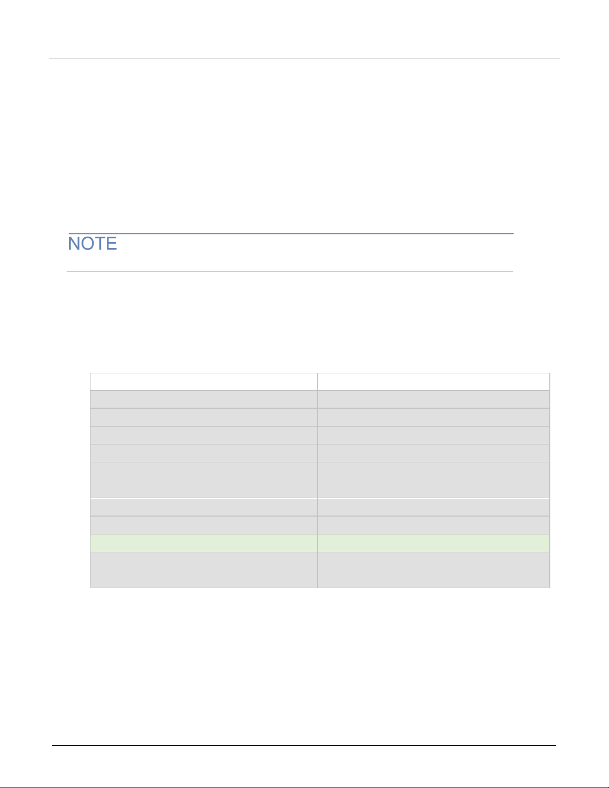
The following table is a comparison of key features between the instruments.
Resolution
DMM input terminals
Plug-in module slots and
channels
Module cards supported
Reading capacity
Non-volatile memory
Basic DCV accuracy
Measurements
DCV, ACV (ranges)
DCI (ranges)
ACI (ranges)
Temperature
Diode
Capacitance
Digitizer
DAQ6510 Model 2700 / Model 2701
6 ½ digits 6 ½ digits
Front Front
Two slots, up to 80 independent
channels
Same
7M 55k
No Yes
30 ppm / 1 year; 35 ppm / 2 year 30 ppm / 1 year
Same
10 μA, 100 μA, 1 mA, 10 mA,
100 mA, 1 A, 3 A
100 μA, 1 mA, 10 mA, 100 mA,
1 A, 3 A
Same
10 V clamp (10 μA, 100 μA, 1 mA,
and 10 mA test currents)
1 nF, 10 nF, 100 nF, 1 μF,
10 μF, 100 μF
Up to 1MS/s voltage or current N/A
Two slots, up to 80 independent
channels
20 mA, 100 mA, 1 A, 3 A
1 A, 3 A
N/A
N/A
Resistance (lowest ranges)
PC interfaces
USB flash drive support
Max scan rate (w/ 7710 card)
Mechanical size
(for rack mounting)
Measurement accuracy and
resolution
SCPI compatibility
1 Ω, 10 Ω, 100 Ω 100 Ω
USB/LAN-LXI (standard)
GPIB/RS-232/TSP-Link (optional)
Yes No
> 800 channels per second (USB) 180 channels per second
2U, ½ rack
14.039 in. (356.6 mm) deep 14.563 in. (370 mm) deep
The datasheet for each model provides specifications. See the
Instruments (http://www.tek.com/keithley) website.
Greater than 90% coverage of the Model 2700 and Model 2701 standard
command set.
GPIB/RS-232 (Model 2700)
LAN/RS-232 (Model 2701)
(Model 2700, GPIB)
500 channels per second
(Model 2701, LAN)
Keithley
2 077146500 / April 2018

DAQ6510 in a Model 2700 or 2701 Application Emulation and Migration Guide
Select the SCPI command set for emulation mode
To use the DAQ6510 as a drop-in replacement in an existing 2700 or 2701 application, you must use the SCPI
2700 or SCPI 2701 command set. This command set includes most of the commands that are available in the
Model 2700 or 2701 product.
You can select the SCPI 2700 or SCPI 2701 command set from the front panel or over the remote interface.
When you change to the SCPI 2700 or SCPI 2701 command set, you must reboot the instrument. You will be
prompted by the front panel to reboot, but you will not be prompted if using remote commands.
Using the front panel:
1. Press the MENU key.
2. Under System, select Settings.
3. Select the button next to Command Set.
4. Select SCPI 2700 or SCPI 2701. You will be prompted to reboot.
5. Select OK.
Using SCPI or TSP remote commands:
For SCPI 2700, send the command:
*lang SCPI2700
For SCPI 2701, send the command:
*lang SCPI2701
Reboot the instrument.
Front-panel operation with the SCPI 2700 or SCPI 2701 command set
When the SCPI 2700 or SCPI 2701 command set is selected, the options available through the front panel are
limited. Emulation mode is intended primarily for remote command operation.
The following topics describe the options that are available when the SCPI 2700 or SCPI 2701 command set is
selected.
Home screen display
When the SCPI 2700 or SCPI 2701 command set is selected, the Home screen is the only main screen
available. The User, Channel, and Functions swipe screens are also available in the swipe screen area.
The options available on the Home screen are described here.
Figure 1: Home screen when the SCPI 2700 command set is selected
077146500 / April 2018 3

DAQ6510 in a Model 2700 or 2701 Application Emulation and Migration Guide
# Screen element Description
System status
1
and event
indicators
MEASURE view
2
area
Swipe screen
3
area
Located at the top of the Home screen. These indicators provide information
about the present state of the instrument. Some of the indicators open up a
dialog box with more information or a settings menu when selected.
Green part of the Home screen; displays the value of the present
measurement.
Blue part of the Home screen. It displays the User and Functions options. If the
rear terminals are selected, Channel options are available.
Status and error indicators when the SCPI 2700 or SCPI 2701 command set is selected
The indicators at the top of the Home screen contain information about instrument settings and states. Some of
the indicators also provide access to instrument settings.
Figure 2: Status and error indicators — SCPI 2700 or SCPI 2701
The communications indicator is at the left. The options you might see here include:
Indicator Meaning
Local
GPIB
RS-232
TCPIP
VXI-11
USBTMC
Telnet
Instrument is controlled from the front panel.
Instrument is communicating through a GPIB
interface.
Instrument is communicating through an RS-232
interface.
Instrument is communicating through a LAN
interface.
Instrument is communicating using VXI-11.
Instrument is communicating through a USB
interface.
Instrument is communicating through Telnet.
The communications indicator displays the type of communications the instrument is using. Select the indicator
to display the present communications settings. Select Change Settings at the bottom of the dialog box to
open the System Communications screen, where you can change the settings.
There is an activity indicator next to the communications indicator. When the instrument is communicating with
a remote interface, the up and down arrows flash.
4 077146500 / April 2018

DAQ6510 in a Model 2700 or 2701 Application Emulation and Migration Guide
If a service request has been generated, SRQ is displayed to the right of the up and down arrows. You can
instruct the instrument to generate a service request (SRQ) when one or more errors or conditions occur. When
this indicator is on, a service request has been generated. This indicator stays on until the serial poll byte is
read or all the conditions that caused SRQ are cleared.
The system event indicator is on the far right side of the instrument status indicator bar. This indicator changes
based on the type of event that occurred.
Press the indicator to open a message screen with a brief description of the error, warning, or event. Press the
Event Log button to see the System Events screen, which contains more detailed descriptions of the events
and options for controlling the types of error events that are displayed on the front panel.
The following table describes the different event indicators and what they mean.
Icon Description
An empty triangle means that no new events were logged in the event log since the last time you
viewed the event log.
A blue circle means that an informational event message was logged. The message is for information
only. This indicates status changes or information that may be helpful. If the Log Command option is
on, it also includes commands.
A yellow triangle means that a warning event message was logged. This message indicates that a
change occurred that could affect operation.
A red triangle means that an error event message was logged. This may indicate that a command
was sent incorrectly.
Event messages
During operation and programming, front-panel messages may be displayed. Messages are information,
warning, or error notifications.
Figure 3: Example front-panel error message
077146500 / April 2018 5

DAQ6510 in a Model 2700 or 2701 Application Emulation and Migration Guide
Menus when the SCPI 2700 or SCPI 2701 command set is selected
When the SCPI 2700 or SCPI 2701 command set is selected, the only menu available from the front panel is
the System Settings menu.
System Settings menu when the SCPI 2700 or SCPI 2701 command set is selected
The System Settings menu is available when the SCPI 2700 or SCPI 2701 command set is selected. The
options are the same as the options when the other command sets are selected, except that the TSP-Link
options in the Communication menu are not available.
Figure 4: Main menu when the SCPI 2700 or SCPI 2701 command set is selected
Model 2700 or 2701 to DAQ6510 hardware interface differences
The following topics detail the differences between the hardware connections used for the Model 2700 or 2701
and the interfaces provided for the DAQ6510.
Remote interfaces
The Model 2700 was supplied with both GPIB and RS-232 interfaces, while the Model 2701 supplied Ethernet
and RS-232 interfaces.
The DAQ6510 is supplied with USB and Ethernet connectors as standard interfaces. The instrument also
supports GPIB, RS-232, and TSP-Link
TSP-Link is not supported in SCPI 2700 or SCPI 2701 emulation modes.
The following communication accessory modules are available for the DAQ6510. These modules are designed
for user installation, and do not require the DAQ6510 to be shipped to Keithley Instruments for service or
adjustment.
KTTI-GPIB – Communication and Digital I/O Accessory
KTTI-RS232 – Communication and Digital I/O Accessory
KTTI-TSP – Communication and Digital I/O Accessory
®
with optional communication accessory modules.
For more information about the communication accessory cards (such as configuration through the front panel
and over the remote interface), visit tek.com/keithley
.
6 077146500 / April 2018

DAQ6510 in a Model 2700 or 2701 Application Emulation and Migration Guide
Digital I/O interface
The Model 2700 and 2701 provide six digital I/O lines on a standard DB-9 connector on the rear panel of the
instrument. The port is output-only in standard mode and also when you use the SCPI 2700 and SCPI 2701
command sets.
The following graphic and table details the digital I/O pinouts.
Figure 5: Model 270x digital I/O pin layouts
Pin 2700 and 2701 functionality
1 Digital output #1 (low limit 1)
2 Digital output #2 (high limit 1)
3 Digital output #3 (low limit 2)
4 Digital output #4 (high limit 2)
5 Digital output #5 (master limit)
6 External trigger (input)
7 Diode clamp
8 Hardware interlock (input)
9 Digital ground (chassis)
The DAQ6510 does not directly provide this interface. However, the same interface is available if you install
one of the KTTI communications accessory cards (see Remote interfaces (on page 6
)).
If you use the SCPI 2700 or SCPI 2701 command set with the DAQ6510 and a KTTI card, the I/O pin mapping
and functionality will match that of the 2700 or 2701, with two exceptions:
Pin 6 is not physically linked to the external trigger line of the trigger link connection, but pin 6 will accept
the external trigger signal from an outside source.
Pin 8 will not enable or disable the external trigger line of the trigger link connection, but pin 8 will still
enable and disable the triggering capability of pin 6.
077146500 / April 2018 7

DAQ6510 in a Model 2700 or 2701 Application Emulation and Migration Guide
The following graphic and table details the DAQ6510 digital I/O pinouts when a KTTI communication accessory
card is installed. The DAQ6510 is output-only when used with the SCPI 2700 or SCPI 2701 command sets.
However, the DAQ6510 standard command set supports six dedicated I/O input and output control lines.
Figure 6: DAQ6510 digital I/O pin layouts
Pin DAQ6510 functionality (with KITT card installed)
1 I/O line #1
2 I/O line #2
3 I/O line #3
4 I/O line #4
5
line (relay flyback diode protection; maximum 33 V)
V
ext
6 I/O line #5
7 +5 V line. Use this pin to drive external logic circuitry. Maximum current
output is 500 mA. This line is protected by a self-resetting fuse (one-hour
recovery time).
8 I/O line #6
9 Ground
Trigger Link and external trigger and voltmeter support
An 8-pin, micro-DIN connector is provided on the rear panel of the Model 2700 and 2701 for sending and
receiving trigger pulses. The voltmeter complete output and external trigger input signals are supported by pin 1
and pin 2, respectively. See the next figure.
Figure 7: Model 2700 and 2701 external trigger connections
The DAQ6510 also supports the external trigger input and voltmeter complete signals, but each trigger line is
routed to a dedicated BNC connection on the rear panel of the DAQ6510.
Figure 8: DAQ6510 external trigger connections
8 077146500 / April 2018

DAQ6510 in a Model 2700 or 2701 Application Emulation and Migration Guide
When using the SCPI 2700 or SCPI 2701 command set, the DAQ6510 trigger signal for voltmeter complete
output is sent to the EXTERNAL TRIGGER OUT connector. External trigger input signals are received through
the EXTERNAL TRIGGER IN connector.
Scan card support
The Model 2700 or 2701 primary use case is scanning multiple channels using any of the twelve module cards
available from Keithley Instruments. All twelve module cards are supported by the DAQ6510 in both emulation
and standard modes. These module cards are as follows:
Model 7700: 20-channel Differential Multiplexer Module
Model 7701: 32-channel Differential Multiplexer Module
Model 7702: 40-channel Differential Multiplexer Module
Model 7703: 32-channel High Speed Differential Multiplexer Module
Model 7705: 40-channel Single-pole Control Module
Model 7706: 20-channel Differential Multiplexer with Automatic CJ
and Counter/Totalizer
Model 7707: 32-channel Digital I/O Module with 10-channel Differential Multiplexer
Model 7708: 40-channel Differential Multiplexer Module with Automatic CJC
Model 7709: 6x8 Matrix Module
Model 7710: 20-channel Solid-state Differential Multiplexer with Automatic CJC
Model 7711: 2 GHz 50 Ω RF Module
C, 16 Digital Outputs, 2 Analog Outputs,
Model 7712: 3.5 GHz 50 Ω RF Module
Visit tek.com/keithley for more information on these s
witching modules.
Model 2700 and 2701 to DAQ6510 software differences
You can use existing code from a Model 2700 or 2701 application with a DAQ6510 — many of the commands
are the same. Apart from the exceptions noted in this section, Model 2700 emulation for the DAQ6510 supports
all SCPI commands that are supported by the Model 2700. Model 2701 emulation for the DAQ6510 supports all
SCPI commands that are supported by the Model 2701.
Details about these differences and other commands that operate differently are described in the following
sections.
If a command is not listed in this section, you can use the command in the same way that you did for the
previous Model 2700 and 2701 products. The descriptions of the commands are provided in the Model 2700 or
Model 2701 User's Manual.
077146500 / April 2018 9

DAQ6510 in a Model 2700 or 2701 Application Emulation and Migration Guide
Temperature Summary (Temp)
SCPI 2700 and SCPI 2701 overview and general exceptions
When you apply the SCPI 2700 or SCPI 2701 command set, the DAQ6510 operation matches Model 2700 or
2701 operation. Commands run as described and have the same defaults as listed in the original Model 2700
or Model 2701 User Manual. However, the following exceptions may affect your test system performance:
Commands run faster than on the Model 2700 and Model 2701.
Measurements are acquired at the same speed or faster than on a Model 2700 or Model 2701.
Error numbers generated in emulation mode (using the SCPI 2700 or SCPI 2701 command set) may not
match the original product.
Autorange may use ranges not available on the original product.
The following items are the general exceptions when you select the SCPI 2701 or SCPI 2700 command set.
Item Exception
Auto scan Non-volatile auto scan is not supported.
Buffer The minimum reading buffer size is 10. The TRAC:POIN command will accept values
less than 10, and you can scan less than 10 channels, but the buffer size will be
adjusted to 10. The Model 2700 and 2701 product default is 2.
AC aperture The DAQ6510 has a fixed aperture for AC voltage and AC current measurements
regardless of the detector bandwidth setting. The Model 2700 and 2701 allowed
NPLC and aperture settings with the detector bandwidth set to 300 Hz.
Frequency and period
aperture
Integration time (NPLC) At a 60 Hz line frequency, NPLC values up to 15 are supported. At a 50 Hz line
Auto delay The auto delay times are derived from hardware design and therefore may not be the
Key clicks and presses Not supported.
The DAQ6510 will only accept values up to 250 ms. The Model 2700 and 2701
product default is 1 s.
frequency, NPLC values up to 12 are supported. Larger values will be accepted and
stored, but the DAQ6510 will use 15 (60 Hz) or 12 (50 Hz).
same as on the Model 2700 and Model 2701. Querying the auto delay duration is not
supported, and will return zero seconds.
Frequency and period
threshold range
Calibration Not supported. You must change the command set to use SCPI or TSP to perform
Front panel defaults The DAQ6510 does not support front panel defaults that differ from remote bus
Display text data When selected, this will appear on the User swipe screen of the Home screen.
Status model The following bits are not supported:
The Model 2700 and Model 2701 maximum range value is 1010 V. The DAQ6510
maximum is 700V.
calibration.
command defaults.
User Request (URQ)
Device-Dependent Error (DDE)
Hardware Limit Event (HL)
Calibration Summary (Cal)
Command Warning (Warn)
Limits The beeper is not supported for limit testing. Limit annunciators (indicators on the
front panel display) are not implemented.
10 077146500 / April 2018

DAQ6510 in a Model 2700 or 2701 Application Emulation and Migration Guide
MATH (mX+b, percent, or reciprocal (1/X) calculation enabled)
*TST?
[,<clist>]
[,<clist>]
DISPlay:TEXT:STATe ON|OFF
ROUTe:CLOSe:COUNt:INTerval
ROUTe:SCAN:BBMake
ROUTe:SCAN:NVOLatile?
SYSTem:KEY?
SYSTem:RWLock
Annunciators The following annunciators are not supported:
HIGH (Reading has reached or exceeded the enabled high limit)
LOW (Reading has reached or exceeded the enabled low limit)
SCPI 2700 and SCPI 2701 command set exceptions
The following are command set exceptions for the SCPI 2700 command set when used on the DAQ6510.
Model 2700 command Exceptions
Not supported. This command will return 0 (passed).
[:SENSe[1]]:FREQuency:THReshold
:
VOLTage:RANGe <n>
[:SENSe[1]]:PERiod:THReshold:
VOLTage:RANGe <n>
[:SENSe[1]]:VOLTage:AC:
REFerence <n> [,<clist>]
[:SENSe[1]]:VOLTage:AC:RANGe
[:UPPer] <n> [,<clist>]
DISPlay:TEXT:DATA <a>
FORM:ELEM?
ROUTe:OPEN:ALL
The maximum range is 700 V. Will accept higher values, but the
range will be set to 700 V. The set value is accepted and stored
for later query.
The maximum range is 700 V. Will accept higher values, but the
range will be set to 700 V. The set value is accepted and stored
for later query.
The maximum range is ± 700 V. Will accept higher values, but
the range will be set to ± 700 V. The set value is accepted and
stored for later query. The Model 2700 and 2701 product
maximum is ± 757.5 V.
The maximum range is 700 V. Will accept higher values, but the
range will be set to 700 V. The set value is accepted and stored
for later query. The Model 2700 and 2701 product maximum
range is 757.5 V.
When enabled, text will appear on line 1 of the user swipe
screen.
The Model 2700 returns extra commas when less than the
maximum elements is set. The DAQ6510 will not return
commas unless more than one element is set.
Rounds values to the nearest of 10, 15, 30, 60, or 1440
If you do not have a switch or control module installed, this
command generates an error.
Not supported.
ROUTe:SCAN:NVOLatile <b>
SYSTem:KCLick <b>
SYSTem:KCLick?
SYSTem:KEY <NRf>
077146500 / April 2018 11
Non-volatile auto scan is not supported. Returns 0 (disabled)
when queried.
The set value is accepted and stored for later query, but is not
supported. You can configure key click only from the front
panel.
Not supported. The query will return -1.
Not supported.

DAQ6510 in a Model 2700 or 2701 Application Emulation and Migration Guide
MANual
<n>
SYSTem:BATTery:STATus?
SYSTem:BOARd:REVision?
:CONTrol:RTS <name>
:ENTer?
:PACE <name>
:SEND <data>
[:CENable]:STATe?
:ENABle?
:NEW <password>
SOURce
MANual
SYSTem:TIME <hr, min, sec>
TRACe:POINts <NRf>
TRIGger:[:SEQuence[1]]:SOURce
UNIT:VOLTage:AC:DB:REFerence
The minimum second specification is 1 s. Hours can be set to
23. The maximum second and minute specification is 59. The
Model 2700 and 2701 default is 0.01 s resolution, 24 maximum
hours, and 60 maximum minutes and seconds.
Minimum buffer size is 10. The Model 2700 and 2701 product
minimum is 2.
Not supported.
Maximum reference is 700. The Model 2700 and 2701 product
maximum is 1000.
The following are command set exceptions for the SCPI 2701 command set when used on the DAQ6510.
Model 2701 command Exceptions
SYSTem:BATTery:PRESent?
SYSTem:BOARd:SNUMber?
SYSTem:COMMunicate:SERial
SYSTem:COMMunicate:SERial
The battery present query will return 0 (not present). The battery
status query will always return "MEMORY LOST".
Not supported. The query will return "UNKNOWN".
Enabling or disabling the RTS/CTS hardware handshaking will turn
off the Xon/Xoff flow control.
Read data from serial port is not supported.
SYSTem:COMMunicate:SERial
SYSTem:COMMunicate:SERial
SYSTem:PASSword
:CDISable <password>
Turning the Xon/Xoff flow control on or off will disable the RTS/CTS
hardware handshaking.
Not supported.
Not supported. Querying the state of protected commands will return
1 (enabled).
[:CENable] <password>
SYSTem:PASSword
Not supported. The query will return 0 (disabled).
:ENABle <b>
SYSTem:PASSword
TRIGger[:SEQuence[1]]:
Not supported.
Not supported.
Trigger model and status model
The DAQ6510 will emulate the trigger model of either the Model 2700 or Model 2701, depending on the
selected SCPI command emulation mode. For details on trigger model behavior in either of these modes, refer
to the trigger model information in the Model 2700 or Model 2701 User's Manual.
The DAQ6510 will also emulate a portion of the status model operation for either the Model 2700 or Model
2701, depending on the selected SCPI command emulation mode. See the previous topics in this section for
more information. For details on the status model behavior in either of these modes, refer to the status model
information in the Model 2700 or Model 2701 User's Manual.
12 077146500 / April 2018
DAQ6510 in a Model 2700 or 2701 Application Emulation and Migration Guide
*RST
SENS:FUNC 'VOLT:DC'
SENS:VOLT:RANG 10
SENS:VOLT:DIG 4
SENS:VOLT:NPLC 10
FORM:ELEM READ, TST, UNIT, RNUM
TRAC:CLE
READ?
Delay 5000
INIT
FETCH?
DAQ6510 application examples using SCPI 2700 and SCPI 2701 emulation
The following series of examples use the DAQ6510 in either SCPI 2700 or SCPI 2701 emulation mode. These
applications were designed using commands in the Model 2700 and 2701 User Manuals.
You may need to make changes so that this code will run in your programming environment. In the following
command tables, the SCPI commands have a light gray background. The light green shaded code represents
pseudocode that will vary depending on the programming environment you use.
Example 1 - Single-point DC voltage measurement
This example uses only SCPI 2700 commands.
This example performs the following operations:
Resets the instrument
Places the instrument in DC voltage measurement mode in the fixed 10 V range using a lengthy
integration time
Displays 3 ½ digits on the front panel and returns the reading with units and the timestamp
Extracts readings with the READ? command (which triggers and retrieves the measurement), then uses
the INIT + FETCH? combination for trigger and measurement extraction
Model 2700 commands executed on the DAQ6510 Description
Place the instrument into a known state
Set function to DC volts
Set fixed range of 10 V
Set display digits (range of 4 to 7)
Set slow integration rate
Return readings and timestamps with units
Clear the reading buffer
Trigger and return a single reading
Wait 5 s to change source voltage
Initiate the trigger model
Return the latest reading
077146500 / April 2018 13

DAQ6510 in a Model 2700 or 2701 Application Emulation and Migration Guide
*RST
TRAC:CLE
INIT:CONT OFF
TRAC:POIN 3600
FORM:DATA ASCII
FORM:ELEM READ, CHAN, UNIT
TRIG:COUN 360
SAMP:COUN 10
TRIG:SOUR TIM
TRIG:TIM 10.0
ROUT:SCAN:TSO IMM
FUNC 'TEMP', (@101:110)
TEMP:TRAN TC, (@101:110)
TEMP:TC:TYPE K, (@101:110)
TEMP:TC:ODET ON
TEMP:RJUN:RSEL INT, (@101:110)
TEMP:DIG 5, (@101:110)
Example 2 - Scanning temperature using thermocouples (long-term test)
This example uses only SCPI 2700 commands.
This example demonstrates how to use the DAQ6510 in SCPI 2700 or SCPI 2701 emulation mode to scan a
set of channels, measure temperature at fixed time intervals, and send the data back to the controlling
computer in real time.
This example performs the following operations:
Clears the buffer and disable continuous trigger
Sizes the buffer for a target number of points
Sets the data format to ASCII and returns readings, channel numbers, and units for each channel
measurement
Enables a timer to trigger a scan of 10 channels every 10 seconds for one hour.
Measures temperature across channels 101 through 110 using Type K thermocouples, uses the internal
CJC (dependent on module card model), and enables open lead detection.
Sets the display digits on the front panel to 4 ½ digits and uses an integration time of 1 PLC
Incrementally extracts the scanned readings for each triggered scan
Model 2700 commands executed on the DAQ6510 Result
int chunkSize = 1
string dudCntr = ""
string rcvBuffer
int accumVals = 0
int bufferSize = 3600
Set the data extraction size to one reading
Create a variable to store the counter for the loop
Create a variable to store the receive buffer
Create a variable to hold the accumulated values
10 channels x 360 scans = 3600 samples
Place the instrument into a known state
Clear the reading buffer
Disable continuous triggering
Set the buffer size
Format data as an ASCII character string
Include units and channel numbers with the reading
Set to respond to 360 trigger events
Capture 10 channels for each triggered scan
Set the trigger source as based on the timer
Set the timer event to issue every 10 seconds
Set the scan trigger source to immediate
Set function to temperature
Set transducer to thermocouples
14 077146500 / April 2018
Set thermocouples to Type K
Turn on open thermocouple detector
Set reference junction to internal
Set display digits

DAQ6510 in a Model 2700 or 2701 Application Emulation and Migration Guide
TEMP:NPLC 1, (@101:110)
ROUT:SCAN (@101:110)
ROUT:SCAN:LSEL INT
*OPC?
INIT
Delay 10000
while accumVals < bufferSize
dudCntr = TRAC:NEXT?
dudCntr = ""
rcvBuffer = TRAC:DATA:SEL? accumVals,
chunksize
END while
*OPC?
ROUT:SEL:LSEL NONE
Set integration rate
Set the scan list
Enable the scan
Check that operations complete
Initiate the scan
Pause for 10 seconds to allow for the interval delay
Begin "while" loop
Check for the last buffer reading
Delay 50
if (dudCntr – accumVals > chunkSize)
OR (dudCntr = 0)
Print rcvBuffer
accumVals = accumVals + chunkSize
rcvBuffer = ""
END if
Allow readings to accumulate
Check that there is a reading to print to the console
window
Return reading for each individual scan performed over
the test period
Print the contents of the receive buffer to the console
window
Increment indexes
End the "while" loop
Hold for the operations to complete
Disable scanning
077146500 / April 2018 15

DAQ6510 in a Model 2700 or 2701 Application Emulation and Migration Guide
*RST
TRAC:POIN 1000
FORM:DATA ASCII
FORM:ELEM READ
SAMP:COUN 1000
FUNC "RES", (@101:110)
RES:RANG 10e3, (@101:110)
RES:NPLC 0.01, (@101:110)
RES:DIG 5, (@101:110)
DISP:ENAB OFF
TRIG:DEL:AUTO OFF
TRIG:DEL 0
RES:AVER:STAT OFF, (@101:110)
CALC3:OUTP OFF
SYST:LSYN OFF
Example 3 - High-speed scanning with the Model 7710 Solid State Multiplexer Module
This example uses only SCPI 2701 commands.
This example demonstrates how to increase scanning speed by disabling features such as autozero and
background filtering.
Using a Model 7710 20-channel scanning card populated with 13 kΩ resistors, all channels are configured for
the fastest possible NPLC (on the Model 2701). A fixed range is used to further increase the scanning speed.
This application is useful for when you want to prioritize measurement collection speed over measurement
noise and accuracy.
This example performs the following operations:
Sets the data format to ASCII and returns only readings
Scans 2-wire resistance across channels 101 through 110 one hundred times on a fixed range, with a fast
integration time (0.01 NPLC)
Disables autodelay, autozero, the front-panel display, trigger delay, math calculations, and limits checking
Extracts the data 50 readings at a time as measurements are made
Re-enables the display once the scanning and data extraction is complete
Model 2701 SCPI commands executed on the
DAQ6510
Description
int chunkSize = 50
string dudCntr = ""
string rcvBuffer
int accumVals = 0
int bufferSize = 1000
Set the data extraction size to one reading
Create a variable to store the counter for the loop
Create a variable to hold the receive buffer
Create a variable to hold the accumulated values
10 channels x 100 scans = 1000 samples
Put the instrument in a known state
Set the buffer size
Format data as an ASCII string
Return the reading with units
Take 1000 readings
Set function to 2-wire resistance
Set fixed range at 10kΩ
Set fast integration rate
Set significant digits
Turn off display
Turn off auto-delay
Set trigger delay to 0 seconds
Disable background statistics/filtering
16 077146500 / April 2018
Turn off limit test
Turn off line-sync

DAQ6510 in a Model 2700 or 2701 Application Emulation and Migration Guide
SYST:AZER:STAT OFF
CALC3:LIM1:STAT OFF, (@101:110)
TRAC:CLE
ROUT:SCAN (@101:110)
ROUT:SCAN:LSEL INT
*OPC?
INIT
Delay 150
while accumVals < 1000
dudCntr = TRAC:NEXT?
DudCntr = ""
rcvBuffer = TRAC:DATA:SEL? accumVals,
chunkSize
*OPC?
ROUT:SCAN:LSEL NONE
DISP:ENAB ON
Turn off auto-zero
Turn off limits
Clear the reading buffer
Set the scan list
Enable the scan
Check that operations complete
Initiate the scan
Delay to allow readings to accumulate
Begin while loop
Check for the last buffer reading
If (dudCntr – accumVals > chunkSize)
OR (dudCntr = 0)
Print rcvBuffer
accumVals = accumVals + chunkSize
END if
END while
Check that there are enough readings to print to the
console
Return readings in chunks of 50
Print the contents of the receive buffer to the console
window
Increment indexes
End loop
Hold for the operations to complete
Disable scanning
Turn the display back on
The following table lists the overall command execution time as well as the throughput results in units of
readings per second. This can help you determine how many measurements you can expect to be returned to
the test program using each instrument. Commands generally run faster in emulation mode on the DAQ6510.
Instrument
Model 2701 3.06 @ 326.88 3.05 @ 327.23
Model 2701 emulation on DAQ6510 2.04 @ 488.52 1.94 @ 513.08
Model 2700 13.56 @ 73.71 -
Model 2700 emulation on DAQ6510 1.80 @ 555.56 -
Run time at data acquisition rate (readings per second)
0.01 PLC 0.002 PLC
077146500 / April 2018 17

DAQ6510 in a Model 2700 or 2701 Application Emulation and Migration Guide
*RST
*RST
SENS:FUNC "VOLT:DC"
SENS:FUNC 'VOLT:DC'
SENS:VOLT:RANG 10
SENS:VOLT:RANG 10
DISP:VOLT:DIG 4
SENS:VOLT:DIG 4
SENS:VOLT:NPLC 10
SENS:VOLT:NPLC 10
FORM:ELEM READ, TST, UNIT, RNUM
TRAC:CLE
TRAC:CLE
READ?
READ?
Delay 5000
INIT
INIT
FETCH?
FETCH?
Updating your code to use DAQ6510 SCPI commands
The DAQ6510 standard SCPI command set lets you access new measurement functions, ranges, and data
analysis tools. However, these new features are not available when using the SCPI 2700 or SCPI 2701
command set, and you cannot run more than one command set at once.
To access these new features, you can modify your existing SCPI code to use the DAQ6510 standard mode
SCPI commands. The examples in this section detail the code changes you can make to the SCPI 2700 or
SCPI 2701 command set applications in the previous section.
You may need to make changes so that this code will run in your programming environment. In the following
command tables, the SCPI commands have a light gray background. The light green shaded code represents
pseudocode that will vary depending on the programming environment you use.
For more information on the functions and features available on the DAQ6510, see the DAQ6510 specification,
available from tek.com/keithley
Example 1 - Single-point DC voltage measurement
This example uses only SCPI 2700 commands.
This example performs the following operations:
.
Resets the instrument
Places the instrument in DC voltage measurement mode in the fixed 10 V range using a lengthy
integration time
Displays 3 ½ digits on the front panel and returns the reading with units and the timestamp
Extracts readings with the READ? command (which triggers and retrieves the measurement), then uses
the INIT + FETCH? combination for trigger and measurement extraction
DAQ6510 SCPI commands Model 2700 SCPI commands
18 077146500 / April 2018

DAQ6510 in a Model 2700 or 2701 Application Emulation and Migration Guide
int bufferSize = 360
int chunkSize = 1
*RST
*RST
TRAC:CLE
TRAC:CLE
INIT:CONT OFF
TRAC:POIN 360, "defbuffer1"
TRAC:POIN 360
FORM:DATA ASCII
FORM:DATA ASCII
FORM:ELEM READ, CHAN, UNIT
FORM:ASC:PREC 4
ROUT:SCAN:COUN:SCAN 36
TRIG:COUN 36
SAMP:COUN 10
TRIG:SOUR TIM
ROUT:SCAN:INT 10
TRIG:TIM 10.0
ROUT:SCAN:TSO IMM
FUNC "TEMP", (@101:110)
FUNC 'TEMP', (@101:110)
TEMP:TRAN TC, (@101:110)
TEMP:TRAN TC, (@101:110)
TEMP:TC:TYPE K, (@101:110)
TEMP:TC:TYPE K, (@101:110)
TEMP:ODET ON
TEMP:TC:ODET ON
TEMP:TC:RJUN:RSEL INT, (@101:110)
TEMP:RJUN:RSEL INT, (@101:110)
DISP:TEMP:DIG 4, (@101:110)
TEMP:DIG 4, (@101:110)
TEMP:NPLC 1, (@101:110)
TEMP:NPLC 1, (@101:110)
ROUT:SCAN:CRE (@101:110)
ROUT:SCAN (@101:110)
ROUT:SCAN:LSEL INT
Example 2 - Scanning temperature using thermocouples (long-term test)
This example uses only SCPI 2700 commands.
This example performs the following operations:
Clears the buffer and disable continuous trigger.
Sizes the buffer for a target number of points.
Sets the data format to ASCII and returns readings, channel numbers, and units for each channel
measurement.
Enables a timer to trigger a scan of 10 channels every 10 seconds for one hour.
Measures temperature across channels 101 through 110 using Type K thermocouples, uses the internal
CJC, and enables open lead detection.
Sets the display digits on the front panel to 4 ½ digits and uses an integration time of 1 PLC.
Incrementally extracts the scanned readings for each triggered scan.
DAQ6510 SCPI Commands Model 2700 SCPI Commands
int chunkSize = 1
string dudCntr = ""
string rcvBuffer
int accumVals = 0
int startIndex
int endIndex
string dudCntr = ""
string rcvBuffer
int accumVals = 0
int bufferSize = 360
077146500 / April 2018 19

DAQ6510 in a Model 2700 or 2701 Application Emulation and Migration Guide
*OPC?
*OPC?
INIT
INIT
Delay 10000
Delay 10000
while accumVals != 1000
while accumVals < bufferSize
dudCntr = TRACe:ACTual:END?
dudCntr = TRAC:NEXT?
Delay 50
dudCntr = ""
endIndex, "debuffer1", READ
rcvBuffer = TRAC:DATA:SEL? accumVals,
chunksize
END while
Print rcvBuffer
*OPC?
*OPC?
ROUT:SEL:LSEL NONE
int bufferSize = 1000
int chunkSize = 50
int bufferSize = 1000
*RST
*RST
FORM:DATA ASCII
FORM:DATA ASCII
FORM:ELEM READ
Delay 50
If (dudCntr – accumVals) >= chunkSize
rcvBuffer = TRAC:DATA? startIndex,
Print rcvBuffer
accumVals = accumVals + chunkSize
startIndex = startIndex + chunkSize;
endIndex = startIndex + (chunkSize -
1);
END if
if (dudCntr – accumVals > chunkSize)
OR (dudCntr = 0)
accumVals = accumVals + chunkSize
rcvBuffer = ""
END if
END while
Example 3 - High-speed scanning with the Model 7710 Solid State Multiplexer Module
This example uses only SCPI 2701 commands.
This example performs the following operations:
Sets the data format to ASCII and returns only readings
Scans 2-wire resistance across channels 101 through 110 one hundred times on a fixed range, with a fast
integration time (0.01 NPLC)
Disables autodelay, autozero, the front-panel display, trigger delay, math calculations, and limits checking
Extracts the data 50 readings at a time as measurements are made
Re-enables the display once the scanning and data extraction is complete
DAQ6510 SCPI commands Model 2700 SCPI commands
int chunkSize = 50
string dudCntr = ""
string rcvBuffer
int accumVals = 0
int startIndex
int endIndex
string dudCntr = ""
string rcvBuffer
int accumVals = 0
20 077146500 / April 2018

DAQ6510 in a Model 2700 or 2701 Application Emulation and Migration Guide
ROUT:SCAN:COUN:SCAN 100
SAMP:COUN 1000
FUNC "RES", (@101:110)
FUNC "RES", (@101:110)
RES:RANG 10e3, (@101:110)
RES:RANG 10e3, (@101:110)
RES:NPLC 0.01, (@101:110)
RES:NPLC 0.01, (@101:110)
DISP:RES:DIG 5, (@101:110)
RES:DIG 5, (@101:110)
DISP:LIGH:STAT OFF
DISP:ENAB OFF
RES:DEL:AUTO OFF
TRIG:DEL:AUTO OFF
ROUT:SCAN:INT 0
TRIG:DEL 0
ROUT:CHAN:DEL 0, (@101,110)
RES:AVER:STAT OFF, (@101:110)
RES:AVER:STAT OFF, (@101:110)
CALC2:RES:LIM1:STAT OFF, (@101:110)
CALC3:LIM1:STAT OFF, (@101:110)
CALC2:RES:LIM2:STAT OFF, (@101:110)
CALC3:OUTP OFF
RES:LINE:SYNC OFF, (@101:110)
SYST:LSYN OFF
RES:AZER:STAT OFF, (@101:110)
SYST:AZER:STAT OFF
TRAC:CLE
TRAC:CLE
TRAC:POIN 1000, "defbuffer1"
TRAC:POIN 1000
ROUT:SCAN:CRE (@101:110)
ROUT:SCAN (@101:110)
ROUT:SCAN:LSEL INT
*OPC?
*OPC?
INIT
INIT
Delay 150
while accumVals != 1000
while accumVals < 1000
dudCntr = TRACe:ACTual:END?
dudCntr = TRAC:NEXT?
If (dudCntr – accumVals > chunkSize)
DudCntr = ""
endIndex, "debuffer1", READ
rcvBuffer = TRAC:DATA:SEL? accumVals,
chunkSize
END while
Print rcvBuffer
*OPC?
*OPC?
ROUT:SCAN:LSEL NONE
DISP:LIGH:STAT ON
DISP:ENAB ON
If (dudCntr – accumVals) >= chunkSize
rcvBuffer = TRAC:DATA? startIndex,
Print rcvBuffer
accumVals = accumVals + chunkSize
startIndex = startIndex + chunkSize;
endIndex = startIndex + (chunkSize -
1);
END if
077146500 / April 2018 21
OR (dudCntr = 0)
accumVals = accumVals + chunkSize
END if
END while

DAQ6510 in a Model 2700 or 2701 Application Emulation and Migration Guide
The following table lists the overall command execution time as well as the throughput results in units of
readings per second. This can help you determine how many measurements you can expect to be returned to
the test program using each instrument. Commands generally run faster in emulation mode on the DAQ6510.
Instrument
Model 2701 3.06 @ 326.88 3.05 @ 327.23
Model 2701 emulation on DAQ6510 2.04 @ 488.52 1.94 @ 513.08
Model 2700 13.56 @ 73.71 -
Model 2700 emulation on DAQ6510 1.80 @ 555.56 -
DAQ6510 0.97 @ 1025.64 1.02 @ 974.66
Run time at data acquisition rate (readings/second)
0.01 PLC 0.002 PLC
22 077146500 / April 2018
 Loading...