

Page 1

Model 2657A High Power
www.keithley.com
System SourceMeter
User’s Manual
2657A-900-01 Rev. A / April 2012
®
Instrument
ECNEDIFNOC FO ERUSAEM RETAERG A
Page 2

Model 2657A
High Power System Sourcemeter® Instrument
User's Manual
© 2012, Keithley Instruments, Inc.
Cleveland, Ohio, U.S.A.
All rights reserved.
Any unauthorized reproduction, photocopy, or use the information herein, in whole or in part,
without the prior written approval of Keithley Instruments, Inc. is strictly prohibited.
®
, TSP-Link®, and TSP-Net® are trademarks of Keithley Instruments, Inc. All Keithley
TSP
Instruments product names are trademarks or registered trademarks of Keithley Instruments, Inc.
Other brand names are trademarks or registered trademarks of their respective holders.
The Lua 5.0 software and associated documentation files are copyright © 1994-2008, Tecgraf,
PUC-Rio. Terms of license for the Lua software and associated documentation can be accessed at
the Lua licensing site (http://www.lua.org/license.html
).
Document number: 2657A-900-01 Rev. A / April 2012
Page 3

Safety Precautions
The following safety precautions should be observed before using this product and any associated instrumentation. Although
some instruments and accessories would normally be used with nonhazardous voltages, there are situations where hazardous
conditions may be present.
This product is intended for use by qualified personnel who recognize shock hazards and are familiar with the safety precautions
required to avoid possible injury. Read and follow all installation, operation, and maintenance information carefully before using
the product. Refer to the user documentation for complete product specifications.
If the product is used in a manner not specified, the protection provided by the product warranty may be impaired.
The types of product users are:
Responsible body is the individual or group responsible for the use and maintenance of equipment, for ensuring that the
equipment is operated within its specifications and operating limits, and for ensuring that operators are adequately trained.
Operators use the product for its intended function. They must be trained in electrical safety procedures and proper use of the
instrument. They must be protected from electric shock and contact with hazardous live circuits.
Maintenance personnel perform routine procedures on the product to keep it operating properly, for example, setting the line
voltage or replacing consumable materials. Maintenance procedures are described in the user documentation. The procedures
explicitly state if the operator may perform them. Otherwise, they should be performed only by service personnel.
Service personnel are trained to work on live circuits, perform safe installations, and repair products. Only properly trained
service personnel may perform installation and service procedures.
Keithley Instruments products are designed for use with electrical signals that are rated Measurement Category I and
Measurement Category II, as described in the International Electrotechnical Commission (IEC) Standard IEC 60664. Most
measurement, control, and data I/O signals are Measurement Category I and must not be directly connected to mains voltage or
to voltage sources with high transient overvoltages. Measurement Category II connections require protection for high transient
overvoltages often associated with local AC mains connections. Assume all measurement, control, and data I/O connections are
for connection to Category I sources unless otherwise marked or described in the user documentation.
Exercise extreme caution when a shock hazard is present. Lethal voltage may be present on cable connector jacks or test
fixtures. The American National Standards Institute (ANSI) states that a shock hazard exists when voltage levels greater than
30 V RMS, 42.4 V peak, or 60 VDC are present. A good safety practice is to expect that hazardous voltage is present in any
unknown circuit before measuring.
Operators of this product must be protected from electric shock at all times. The responsible body must ensure that operators
are prevented access and/or insulated from every connection point. In some cases, connections must be exposed to potential
human contact. Product operators in these circumstances must be trained to protect themselves from the risk of electric shock. If
the circuit is capable of operating at or above 1000 V, no conductive part of the circuit may be exposed.
Do not connect switching cards directly to unlimited power circuits. They are intended to be used with impedance-limited
sources. NEVER connect switching cards directly to AC mains. When connecting sources to switching cards, install protective
devices to limit fault current and voltage to the card.
Before operating an instrument, ensure that the line cord is connected to a properly-grounded power receptacle. Inspect the
connecting cables, test leads, and jumpers for possible wear, cracks, or breaks before each use.
When installing equipment where access to the main power cord is restricted, such as rack mounting, a separate main input
power disconnect device must be provided in close proximity to the equipment and within easy reach of the operator.
For maximum safety, do not touch the product, test cables, or any other instruments while power is applied to the circuit under
test. ALWAYS remove power from the entire test system and discharge any capacitors before: connecting or disconnecting
cables or jumpers, installing or removing switching cards, or making internal changes, such as installing or removing jumpers.
Do not touch any object that could provide a current path to the common side of the circuit under test or power line (earth)
ground. Always make measurements with dry hands while standing on a dry, insulated surface capable of withstanding the
voltage being measured.
11/07
Page 4
The instrument and accessories must be used in accordance with its specifications and operating instructions, or the safety of
the equipment may be impaired.
Do not exceed the maximum signal levels of the instruments and accessories, as defined in the specifications and operating
information, and as shown on the instrument or test fixture panels, or switching card.
When fuses are used in a product, replace with the same type and rating for continued protection against fire hazard.
Chassis connections must only be used as shield connections for measuring circuits, NOT as safety earth ground connections.
If you are using a test fixture, keep the lid closed while power is applied to the device under test. Safe operation requires the use
of a lid interlock.
If a screw is present, connect it to safety earth ground using the wire recommended in the user documentation.
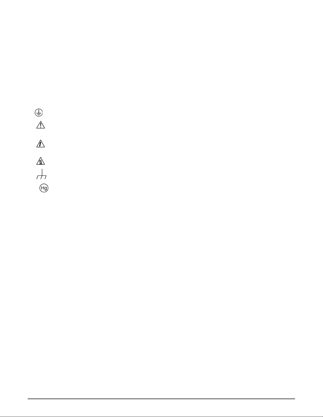
The
symbol on an instrument means caution, risk of danger. The user should refer to the operating instructions located in
the user documentation in all cases where the symbol is marked on the instrument.
The
symbol on an instrument means caution, risk of electric shock. Use standard safety precautions to avoid personal
contact with these voltages.
The
The
symbol on an instrument shows that the surface may be hot. Avoid personal contact to prevent burns.
symbol indicates a connection terminal to the equipment frame.
If this symbol is on a product, it indicates that mercury is present in the display lamp. Please note that the lamp must be
properly disposed of according to federal, state, and local laws.
The WARNING heading in the user documentation explains dangers that might result in personal injury or death. Always read
the associated information very carefully before performing the indicated procedure.
The CAUTION heading in the user documentation explains hazards that could damage the instrument. Such damage may
invalidate the warranty.
Instrumentation and accessories shall not be connected to humans.
Before performing any maintenance, disconnect the line cord and all test cables.
To maintain protection from electric shock and fire, replacement components in mains circuits — including the power
transformer, test leads, and input jacks — must be purchased from Keithley Instruments. Standard fuses with applicable national
safety approvals may be used if the rating and type are the same. Other components that are not safety-related may be
purchased from other suppliers as long as they are equivalent to the original component (note that selected parts should be
purchased only through Keithley Instruments to maintain accuracy and functionality of the product). If you are unsure about the
applicability of a replacement component, call a Keithley Instruments office for information.
To clean an instrument, use a damp cloth or mild, water-based cleaner. Clean the exterior of the instrument only. Do not apply
cleaner directly to the instrument or allow liquids to enter or spill on the instrument. Products that consist of a circuit board with
no case or chassis (e.g., a data acquisition board for installation into a computer) should never require cleaning if handled
according to instructions. If the board becomes contaminated and operation is affected, the board should be returned to the
factory for proper cleaning/servicing.
11/07
Page 5

Table of Contents
Introduction .............................................................................................................. 1-1
Welcome .............................................................................................................................. 1-1
Extended warranty ............................................................................................................... 1-1
Introduction to this manual ................................................................................................... 1-1
CD-ROM contents ................................................................................................................ 1-2
Organization of manual sections .......................................................................................... 1-3
Applications .......................................................................................................................... 1-3
Safe configuration and test setup ........................................................................... 2-1
Introduction .......................................................................................................................... 2-1
Using the Model 2657A with the Model 8010 test fixture ..................................................... 2-1
Using the Model 2657A in a custom test fixture or system .................................................. 2-3
Connecting the interlock of the Model 2657A ............................................................................ 2-3
Connecting the Model 2657A output to a custom test fixture .................................................... 2-4
Four-wire connections to a test fixture with HV triaxial connectors ........................................... 2-9
Using the front-panel interface ............................................................................... 3-1
Introduction .......................................................................................................................... 3-1
Front panel ........................................................................................................................... 3-2
Placing a Model 2657A in standby ............................................................................................ 3-4
Changing values from the front panel ....................................................................................... 3-4
Using the web interface ........................................................................................... 4-1
Introduction .......................................................................................................................... 4-1
Connecting to the instrument web interface......................................................................... 4-1
Web interface home page .................................................................................................... 4-2
IP configuration tab .............................................................................................................. 4-3
TSB Embedded .................................................................................................................... 4-4
Create a script using TSB Embedded ....................................................................................... 4-4
Exercise: Create and run a script with TSB Embedded ............................................................ 4-4
Reading buffers .................................................................................................................... 4-7
Exercise: Retrieve readings from a buffer ................................................................................. 4-7
TSP Express ........................................................................................................................ 4-9
Making basic front-panel measurements ............................................................... 5-1
Introduction .......................................................................................................................... 5-1
Equipment needed for this example .................................................................................... 5-1
Device connections .............................................................................................................. 5-2
Page 6

Table of Contents
User's Manual
Model 2657A High Power System Sourcemeter® Instrument
Making front-panel measurements ...................................................................................... 5-4
Procedure for making front-panel measurements ..................................................................... 5-4
Measuring diode off-state breakdown .................................................................... 6-1
Introduction .......................................................................................................................... 6-1
Equipment required .............................................................................................................. 6-1
Set up communication.......................................................................................................... 6-2
Device connections .............................................................................................................. 6-3
Simple reverse voltage sweep ............................................................................................. 6-5
Example code ........................................................................................................................... 6-5
Example usage ......................................................................................................................... 6-8
Advanced reverse voltage sweep ........................................................................................ 6-9
Example code ........................................................................................................................... 6-9
Example usage ....................................................................................................................... 6-12
Measuring capacitor leakage .................................................................................. 7-1
Introduction .......................................................................................................................... 7-1
Equipment required .............................................................................................................. 7-1
Set up communication.......................................................................................................... 7-2
Device connections .............................................................................................................. 7-2
Measuring leakage current and insulation resistance .......................................................... 7-4
Example code ........................................................................................................................... 7-4
Example usage ......................................................................................................................... 7-6
Measuring MOSFET characteristics ....................................................................... 8-1
Introduction .......................................................................................................................... 8-1
Equipment required .............................................................................................................. 8-1
Set up communication.......................................................................................................... 8-2
Device connections .............................................................................................................. 8-3
BVdss measurement ............................................................................................................ 8-6
Example code ........................................................................................................................... 8-7
Example usage ......................................................................................................................... 8-8
Idss measurement ................................................................................................................ 8-9
Example code ........................................................................................................................... 8-9
Example usage ....................................................................................................................... 8-11
Measuring thyristor DC characteristics .................................................................. 9-1
ii 2657A-900-01 Rev. A / April 2012
I ntroduction ......................................................................................................................... 9-1
Equipment required for this example ................................................................................... 9-1
Set up communication.......................................................................................................... 9-2
Device connections .............................................................................................................. 9-3
Page 7

Model 2657A
of Contents
High Power System Sourcemeter® Instrument User's Manual Table
Vdrm and Idrm thyristor measurements ............................................................................... 9-6
Example code ........................................................................................................................... 9-6
Example usage ......................................................................................................................... 9-8
Determine the holding current of a thyristor ....................................................................... 9-10
Example code ......................................................................................................................... 9-10
Example usage ....................................................................................................................... 9-12
Determine the latching current of a thyristor ...................................................................... 9-12
Example code ......................................................................................................................... 9-13
Example usage ....................................................................................................................... 9-15
Troubleshooting FAQs .......................................................................................... 10-1
About this section ............................................................................................................... 10-1
How do I change the line frequency or voltage? ................................................................ 10-1
Where can I find updated drivers? ..................................................................................... 10-2
Can I convert to coaxial cables? ........................................................................................ 10-2
How do I connect LO terminals of multiple SMUs together? ............................................. 10-2
What should I do if I get an 802 interlock error? ................................................................ 10-3
Why is the reading value 9.91e37? .................................................................................... 10-3
Why is the reading value 9.92e37? .................................................................................... 10-3
Next steps ............................................................................................................... 11-1
Additional Model 2657A information .................................................................................. 11-1
Index .................................................................................................................. Index-1
2657A-900-01 Rev. A / April 2012 iii
Page 8

Page 9

Applications .............................................................................. 1-3
Welcome
Section 1
Introduction
In this section:
Welcome .................................................................................. 1-1
Extended warranty ................................................................... 1-1
Introduction to this manual ....................................................... 1-1
CD-ROM contents .................................................................... 1-2
Organization of manual sections .............................................. 1-3
Thank you for choosing a Keithley Instruments product. The Model 2657A High Power System
SourceMeter
®
Instrument provides manufacturers of electronic components and semiconductor
devices with an instrument that combines source and measurement capabilities in a single instrument
called a source-measure unit (also called a SMU). This combination simplifies test processes by
eliminating synchronization and connection issues associated with multiple instrument solutions.
A Model 2657A provides a scalable, high throughput, highly cost-effective solution for precision DC,
pulse, and high voltage source-measure testing that also maintains code compatibility with the Series
2600A instruments.
Extended warranty
Additional years of warranty coverage are available on many products. These valuable contracts
protect you from unbudgeted service expenses and provide additional years of protection at a fraction
of the price of a repair. Extended warranties are available on new and existing products. Contact your
local Keithley Instruments representative for details.
Introduction to this manual
This manual provides detailed tutorials to help you achieve success with your Keithley Instruments
Model 2657A High Power System SourceMeter
basics of the two simplest Model 2657A interfaces, the front panel and the web interface, to
familiarize you with the instrument. You can also familiarize yourself with the instrument by running
the examples in this manual that are relevant to your intended use and to the equipment you are
using.
®
Instrument. In addition, this manual provides the
Some of the examples in this manual may use unfamiliar commands and concepts. For detailed
information about these, refer to the Reference Manual (part number 2657A-901-01) on the Product
Information CD-ROM that came with your instrument.
Page 10

Section
User's Manual
1: Introduction Model 2657A High Power System Sourcemeter® Instrument
CD-ROM contents
Two CD-ROMs are shipped with each Series 2650A instrument:
• The Series 2650A Product Information CD-ROM (Keithley Instruments part number
2650AS-950-01)
• Test Script Builder Integrated Development Environment CD-ROM (Keithley Instruments part
number KTS-850)
The Series 2650A Product Information CD-ROM contains:
• Quick Start Guide: Provides unpacking instructions, describes basic connections, and reviews
basic operation information. If you are new to Keithley Instruments equipment, refer to the Quick
Start Guide to take the steps needed to unpack, set up, and verify operation.
• User's Manual: Provides application examples. If you need a starting point to begin creation of
applications, refer to the User's Manual for a variety of specific examples.
• Reference Manual: Includes advanced operation topics and maintenance information.
Programmers looking for a command reference, and users looking for an in-depth description of
the way the instrument works (including troubleshooting and optimization), should refer to the
Reference Manual.
• Model 8010 High Power Test Fixture Interconnection Reference Guide: A quick reference for
making typical test connections using the optional Model 8010 test fixture.
• Model 8010 High Power Test Fixture User's Manual: Provides complete connection
information and sample applications for the optional Model 8010 test fixture.
• Accessories information: Documentation for available accessories.
• Model 2657A TSB Add-in: Additional tools for the Test Script Builder Integrated Development
Environment (TSB), including Model 2657A-specific examples and help files.
• Drivers and release notes: IVI Instrument Driver, National Instruments LabVIEW™ driver, and
related release notes.
• J2SE™ Runtime Environment: Web browser plug-in that is required to run the web applications
that are available through the instrument web interface.
• Keithley I/O layer and release notes: The Keithley I/O layer manages communications between
Keithley Instruments drivers and software applications and the Model 2657A.
• Keithley LXI Discovery Browser: Identifies the IP addresses of instruments connected to the
local area network (LAN) that support VXI-11 discovery protocol.
For the latest drivers and additional support information, see the Keithley Instruments website
(http://www.keithley.com).
The Test Script Builder Integrated Development Environment CD-ROM contains:
• The installation files for the Test Script Builder Integrated Development Environment. This
software provides an environment in which you can develop a test program and the ability to load
the test program onto the instrument. Running a program that is loaded on the instrument
eliminates the need to send individual commands from the host computer to the instrument when
1-2 2657A-900-01 Rev. A / April 2012
running a test.
Page 11

Model 2657A
Introduction
High Power System Sourcemeter® Instrument User's Manual Section 1:
Organization of manual sections
This manual is organized into the following sections:
• Safe configuration and test setup (on page 2-1): Describes how to use the Model 2657A with the
optional Keithley Instruments Model 8010 High Power Device Test Fixture or a custom test fixture
or system.
• Using the front-panel interface (on page 3-1): Describes the basics of using the front-panel
interface.
• Using the web interface (on page 4-1): Describes the basics of using the web interface.
• Applications (described below) that provide detailed examples of how to use the Model 2657A.
• Troubleshooting FAQs (on page 10-1): Provides answers to frequently asked questions to help
you troubleshoot common problems encountered with the Model 2657A.
• Next steps (on page 11-1): Provides information about additional resources that can help you use
the Model 2657A.
Bookmarks for each section are provided in the PDF version. The manual sections are also listed in
the Table of Contents located at the beginning of this manual.
For more information about bookmarks, see Adobe
®
Acrobat® or Reader® help.
Applications
In addition to being a stand-alone instrument, the Keithley Instruments Model 2657A can intelligently
connect to other instruments and multiple devices. This manual provides application examples that
guide you through several common instrument-to-instrument scenarios. These applications are
presented after the summary information about the Model 2657A, and include:
• Making basic front-panel measurements (on page 5-1): Demonstrates the basic measurement
function using a single Model 2657A and a two-terminal device under test (DUT).
• Measuring diode off-state breakdown (on page 6-1): Two examples demonstrate how to use the
Model 2657A to measure the reverse breakdown characteristics of a high voltage diode. The
Model 2657A measures the leakage current as the reverse voltage is swept to the specified
breakdown voltage of the diode.
• Measuring capacitor leakage (on page 7-1): Demonstrates how to use the Model 2657A to
measure the leakage current and calculate the insulation resistance of a capacitor.
• Measuring MOSFET characteristics (on page 8-1): Two examples demonstrate how to use the
Model 2657A to measure the drain to source breakdown voltage and leakage current of a
MOSFET. These tests perform the BV
• Measuring thyristor DC characteristics (on page 9-1): Three examples demonstrate how to use
the Model 2657A to characterize several DC characteristics of gated thyristors.
measurement and I
dss
measurements.
dss
2657A-900-01 Rev. A / April 2012 1-3
Page 12

Page 13

Using the Model 2657A in a custom test fixture or system ....... 2-3
In this section:
Introduction .............................................................................. 2-1
Using the Model 2657A with the Model 8010 test fixture ......... 2-1
Introduction
The Model 2657A can generate hazardous voltages. It is intended for use with a test fixture or in a
test system that has safety mechanisms in place to prevent an operator from accessing these
voltages.
This section describes how to use the Model 2657A with:
Section 2
Safe configuration and test setup
• The optional Keithley Instruments Model 8010 High Power Device Test Fixture
• A custom test fixture or system
Using the Model 2657A with the Model 8010 test fixture
The Model 8010 test fixture is designed to safely and easily interface to the Model 2657A for quick
testing of a variety of packaged devices.
Only one Model 2657A may be connected to the Model 8010. However, you can connect other
Keithley SourceMeter Instruments (SMUs) to the Model 8010 for testing multi-pin devices. See the
Model 8010 User's Manual for a list of supported instruments.
The Model 8010 provides a safety interlock for up to six SMUs, including the Model 2657A. Opening
the test fixture lid disables the output of any SMU that can produce hazardous live voltages (more
than 42 V
To connect the safety interlock from the Model 8010 to the Model 2657A, use the CA-558-2 cable
assembly. This cable is supplied with the Model 8010. The cable assembly connects the safety
interlock pins on the digital I/O connector of the Model 2657A to any one of the Series 26xxA Interlock
connectors on the rear panel of the Model 8010. See
connections (on page 2-2) for connection details.
The Model 2657A is provided with an interlock circuit that must be positively activated in
order for the high voltage output to be enabled. The interlock helps facilitate safe operation
of the equipment in a test system. Bypassing the interlock could expose the operator to
hazardous voltages that could result in personal injury or death.
). Closing and latching the lid enables testing with hazardous voltages.
peak
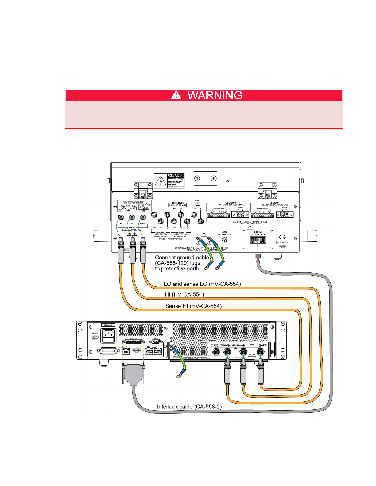
Model 8010 to Model 2657A rear panel
Page 14
Section
User's Manual
2: Safe configuration and test setup Model 2657A High Power System Sourcemeter® Instrument
To connect the Model 2657A output to the Model 8010, use only Model HV-CA-554 high-voltage
triaxial cable assemblies. See the following figure for connections.
Be sure to connect the Model 8010 to protective earth (safety ground) using the screws on its rear
panel.
The ground wires must be attached to a known protective earth (safety ground) before
powering on instruments. Failure to attach the ground wires to a known protective earth may
result in electric shock.
Refer to the Model 8010 User's Manual for additional details.
Figure 1: Model 8010 to Model 2657A rear panel connections
2-2 2657A-900-01 Rev. A / April 2012
Page 15
Model 2657A
Safe configuration and test setup
High Power System Sourcemeter® Instrument User's Manual Section 2:
Using the Model 2657A in a custom test fixture or system
You can use the Model 2657A safely with a properly designed custom test fixture or with a
semiconductor device prober or handler.
Connect the enclosure of all metal test fixtures to protective earth (safety ground).
Nonconductive test fixtures must be rated to double the maximum capability of the test
equipment in the system. Failure to attach the ground wires to a known protective earth may
result in electric shock.
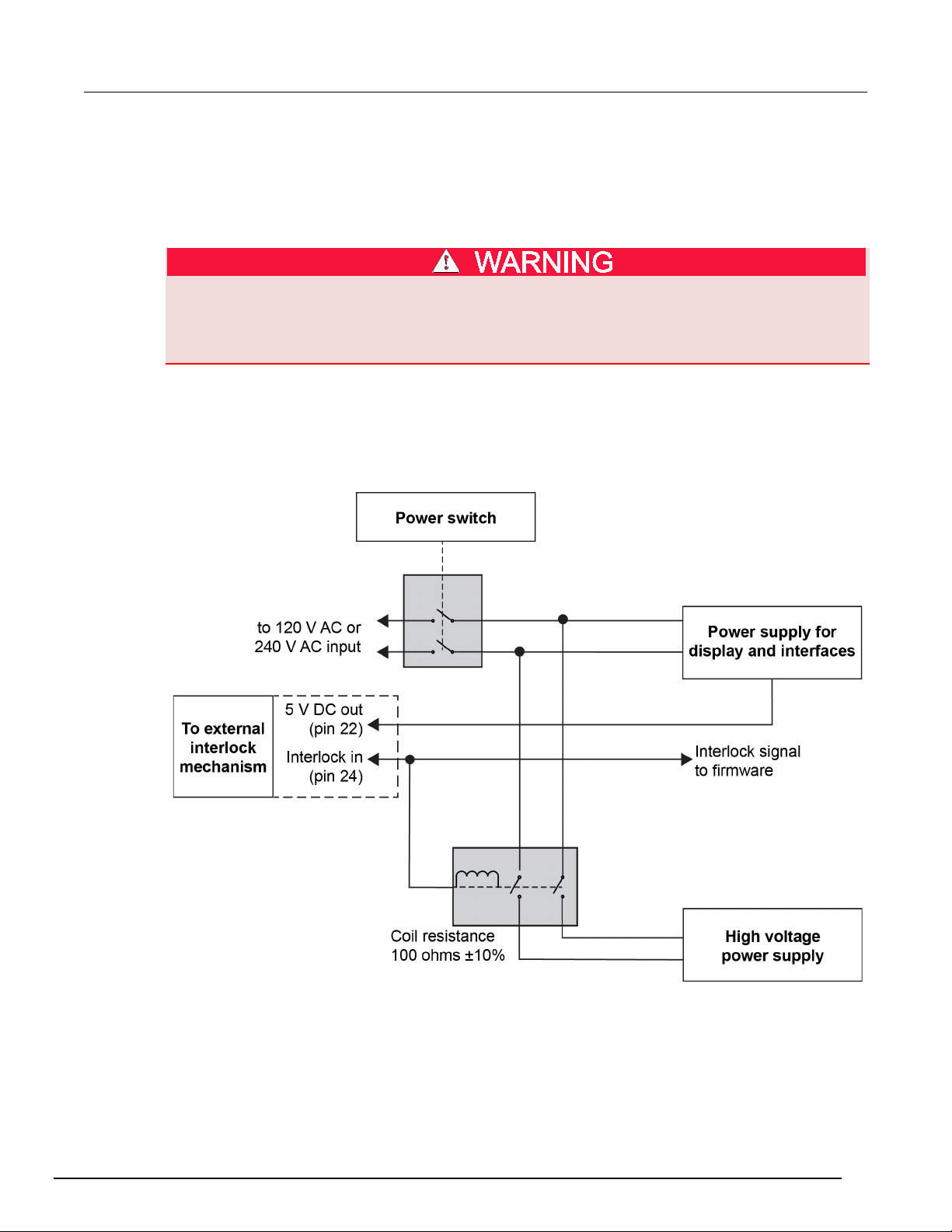
Connecting the interlock of the Model 2657A
The graphic below shows how the interlock pin controls the high voltage supply.
Figure 2: Interlock control of the high voltage power supply
2657A-900-01 Rev. A / April 2012 2-3
Page 16

Section
User's Manual
2: Safe configuration and test setup Model 2657A High Power System Sourcemeter® Instrument
The output of the Model 2657A can only be turned on when the interlock is engaged. Attempting to
turn on the output when the interlock is disengaged will generate error code 802, "Output Blocked by
Interlock."
The interlock is engaged when the interlock pin is pulled high through a switch to more than +4 V. To
drive the interlock pin high, the external supply must supply a minimum of 50 mA. The interlock is
disengaged when the signal applied is less than +4 V. The absolute maximum input is −0.4 V to
+6.0 V.
The interlock is intended for use through a normally open switch, which may be installed on the lid of
a test fixture, on the enclosure of a semiconductor prober or device handler, or on the door or doors
of a test equipment rack.
Connecting the Model 2657A output to a custom test fixture
Keithley Instruments offers several accessories that can help you when building a custom test fixture
or system.
You can use high voltage coaxial or triaxial connectors on your test fixture. The following sections
show you how to connect from the Model 2657A to the custom fixture and also how to make
connections to the device inside the custom fixture.
Using coaxial connections (SHV)
You may need to adapt connections from the Model 2657A to safe high-voltage (SHV) coaxial
connections in your test system. For this situation, you can use the Keithley Instruments
Model SHV-CA-553 high-voltage triaxial to SHV cable assemblies.
The inner shield of the high-voltage triaxial connector is not carried to the SHV connector end. The
result of this is that portions of the test setup are unguarded. This can increase source and
measurement settling time. It can also degrade low-current measurement performance.
Figure 3: High-voltage triaxial to SHV cable assembly (SHV-CA-553)
Figure 4: High-voltage triaxial to SHV coaxial cable assembly schematic
2-4 2657A-900-01 Rev. A / April 2012
Page 17

Model 2657A
Safe configuration and test setup
High Power System Sourcemeter® Instrument User's Manual Section 2:
Be aware that when you connect the Model SHV-CA-553 cable assembly to the SLO/LO triaxial
connector on the rear panel of the Model 2657A, the LO terminal is the inner (or first) shield.
Therefore, the LO terminal is not carried to the SHV end of the Model SHV-CA-553 cable assembly.
Use the LO triaxial connector on the rear panel of the Model 2657A to access Output LO.
If you need to convert from safe high-voltage (SHV) to another connector type, be sure to
only adapt SHV connectors to connectors that are rated to the maximum possible voltage in
your test setup. If you use adapters that are not rated to the maximum possible voltage in
your test setup, electric shock may result.
Four-wire connections to a test fixture with SHV connectors
The following figure is an example that demonstrates the 4-wire connections from the Model 2657A to
a resistor installed in a custom test fixture with SHV connectors.
Figure 5: Four-wire connections to a custom test fixture with SHV connectors
2657A-900-01 Rev. A / April 2012 2-5
Page 18
Section
User's Manual
1
Model 2657A protective earth (safety
1
Additional connections for redundant protective
protective earth (safety ground) cable assembly.
2
Interlock connection
1
Model 2657A digital I/O; pin 24 (INT) and pin 22
connection
4
Interlocked metal safety enclosure
1
A safety enclosure with an interlock that has a
normally-open (NO) switch.
5
Test fixture protective earth (safety
ground)
1
Redundant grounds may be required for specific
test setups.
6
Sense HI, HI, LO, and sense LO
panel-mount SHV connections
4
Customer-supplied.
7
Model SHV-CA-553 High-Voltage
Triaxial to SHV Cable
4
8
Model 2657A
1
2: Safe configuration and test setup Model 2657A High Power System Sourcemeter® Instrument
Item Description Qty Notes
ground)
earth may be required.
Keithley Instrument's Model CA-568 is a
(5 VDC) connected to the test fixture lid switch.
Keithley Instrument's Model 7709-308 is a 25-pin
interlock male connector that can be used for
custom connections.
Interlock switch is shown in the disengaged (lid
open) position.
3 Test fixture interlock switch
1
Figure 6: Physical four-wire connections to a test fixture with SHV connectors
2-6 2657A-900-01 Rev. A / April 2012
Page 19

Model 2657A
Safe configuration and test setup
1
Outer jacket
2
Outer shield
Spacing between the inner shield and any user accessible circuit: 33.5
16.75 mm
4
Center conductor
Spacing between the center conductor:
And a metal enclosure (if used): 16.75 mm
5
First dielectric
6
Second dielectric
7
Inner jacket
With wrapped tape barrier. Minimum spacing between inner and outer
High Power System Sourcemeter® Instrument User's Manual Section 2:
Using high-voltage triaxial connectors
You may use the Keithley Instruments HV-CA-571-3 cable assembly to create custom test fixtures or
systems with panel-mount high-voltage triaxial connectors. Use the HV-CA-554 cable assemblies to
connect the Model 2657A to these custom test fixtures.
Figure 7: Connect to custom test fixtures with the HV-CA-571-3 cable assembly
The HV-CA-571-3 is supplied with one unterminated end. It is intended to be used in a safe
enclosure.
To properly connect the unterminated end to points in your test circuit, ensure proper voltage spacing
for the maximum possible voltage in your test system. For 3000 V, ensure these spacings:
Figure 8: Voltage spacing
Item Description Notes
3 Inner shield
mm; spacing between the inner shield and a metal enclosure (if used):
• And any user accessible circuit: 33.5 mm
•
2657A-900-01 Rev. A / April 2012 2-7
shield: 16.75 mm.
Page 20
Section
User's Manual
2: Safe configuration and test setup Model 2657A High Power System Sourcemeter® Instrument
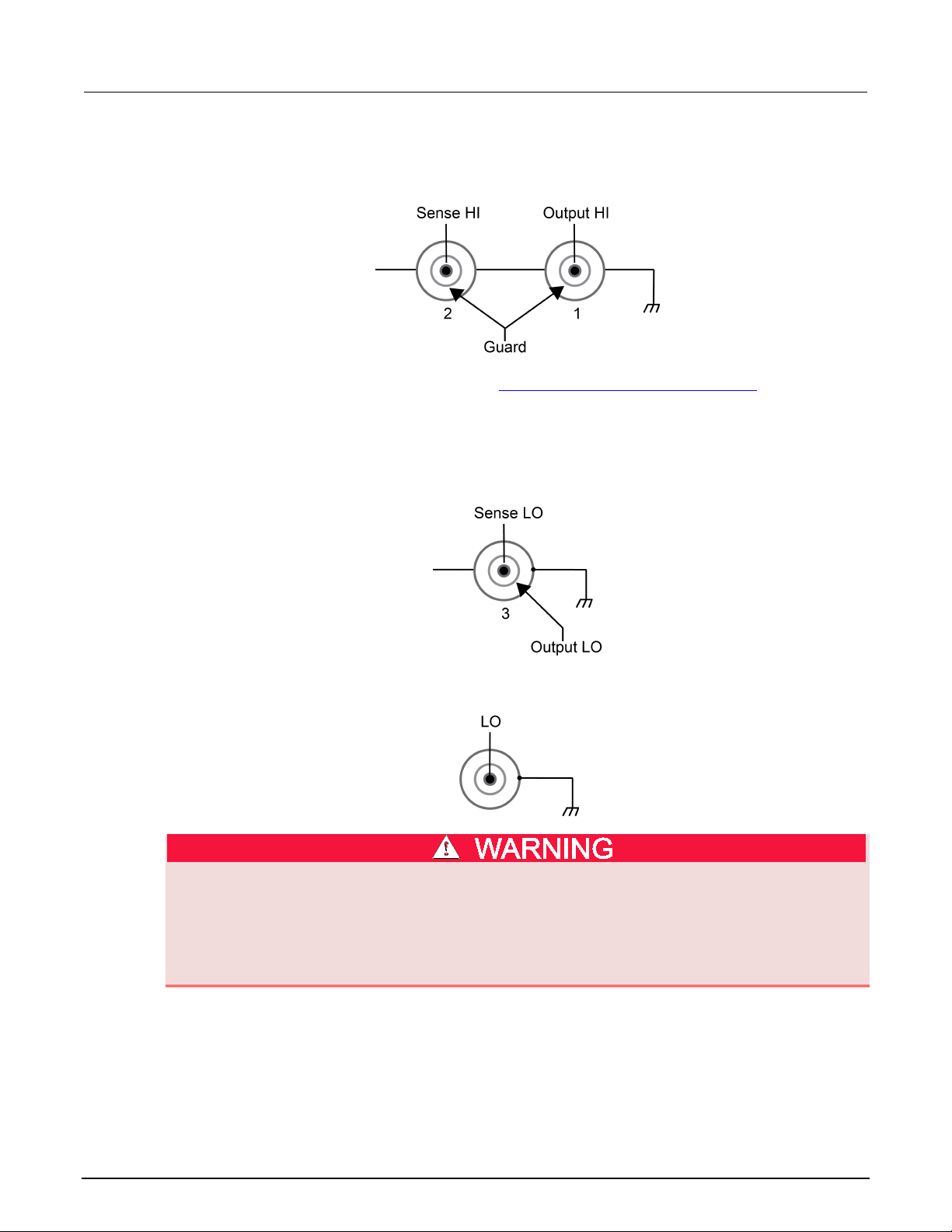
Please note how the above spacing requirements relate to the output terminals of the Model 2657A:
Figure 9: Model 2657A HI and SHI terminals
Follow all spacing requirements as described in Using high-voltage triaxial connectors (on page 2-7).
For the Sense LO and LO terminals, the center conductor and first shield should be within a few volts
of each other to guarantee normal operation. Therefore, there is minimal space required between
these two conductors.
Figure 10: Model 2657A Sense LO and output LO terminal
Figure 11: Model 2657A LO terminal
Connections to LO on the Model 2657A are not necessarily at 0 V. Hazardous voltages could
exist between LO and chassis ground. Make sure that high-voltage precautions are taken
throughout the test system. Alternatively, limit hazardous levels by adding external
protection to limit the voltage between LO and chassis. Failure to make sure high-voltage
precautions are used throughout the test system or a failure to limit hazardous levels could
result in severe personal injury or death from electric shock.
2-8 2657A-900-01 Rev. A / April 2012
Page 21

Model 2657A
Safe configuration and test setup
High Power System Sourcemeter® Instrument User's Manual Section 2:
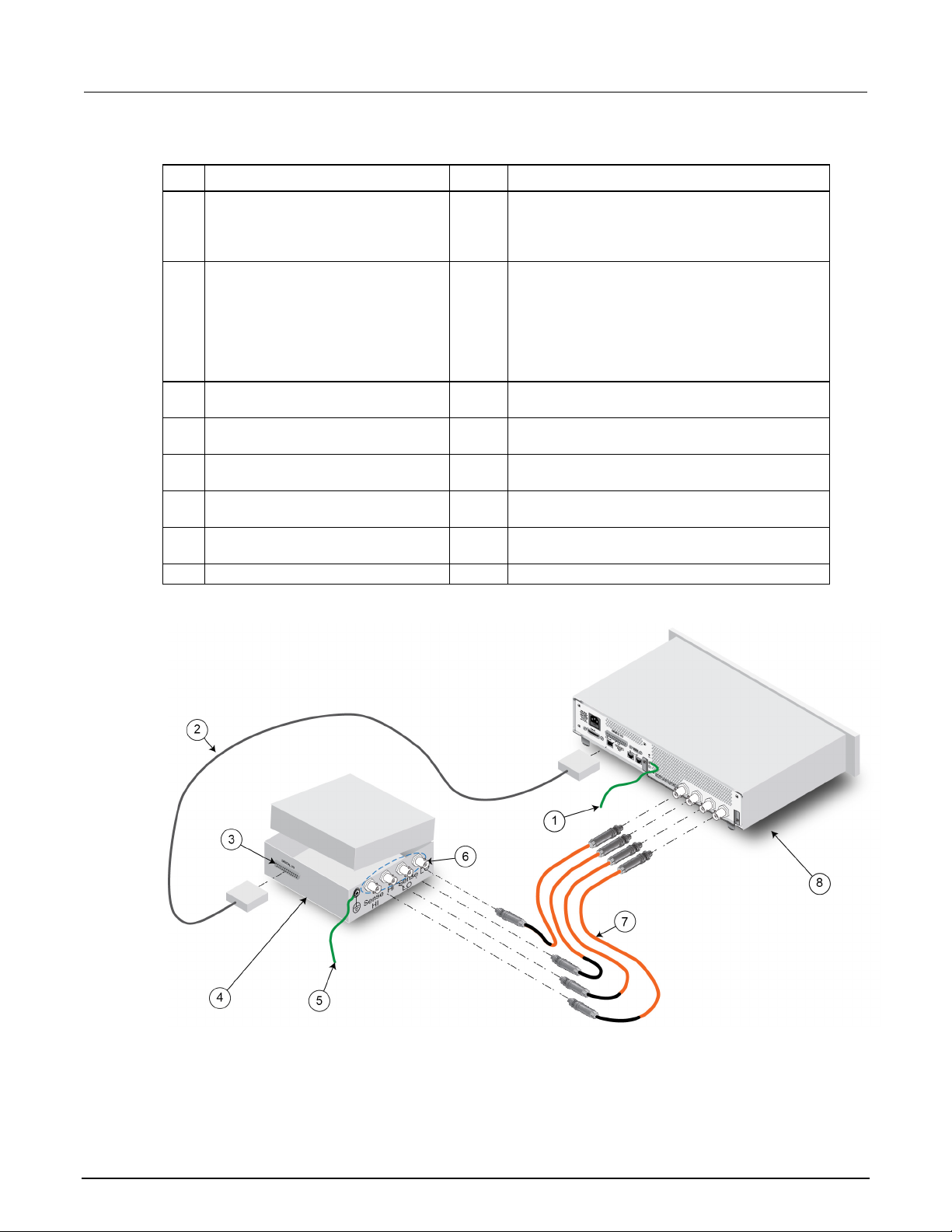
Four-wire connections to a test fixture with HV triaxial connectors
The following graphic demonstrates 4-wire connections from the Model 2657A to a resistor in a
custom test fixture that uses Keithley Instruments high-voltage triaxial connectors.
You may need additional connections for redundant protective earth (safety ground) that are not
shown in the following graphic.
Hazardous voltages may be present on all output and guard terminals. To prevent electrical
shock that could cause injury or death, never make or break connections to the Model 2657A
while the instrument is powered on. Turn off the equipment from the front panel or
disconnect the main power cord from the rear of the Model 2657A before handling cables.
Putting the equipment into standby does not guarantee that the outputs are powered off if a
hardware or software fault occurs.
Figure 12: Model 2657A four-wire connections (remote sensing)
2657A-900-01 Rev. A / April 2012 2-9
Page 22

Section
User's Manual
1
Model 2657A protective earth (safety
1
Additional connections for redundant protective
protective earth (safety ground) cable assembly.
2
Interlock connection
1
Model 2657A digital I/O pin 24 (INT) and pin 22
connection
4
Interlocked metal safety enclosure
1
A safety enclosure with an interlock that has a
normally-open (NO) switch.
5
Test fixture protective earth (safety
ground)
1
Redundant grounds may be required for specific
test setups.
6
Model HV-CA-571-3 High-Voltage
Unterminated Cable Assembly
3
See schematic for connections. Refer to Using
Triaxial Cable
8
Model 2657A
1
2: Safe configuration and test setup Model 2657A High Power System Sourcemeter® Instrument
Item Description Qty Notes
ground)
earth may be required.
Keithley Instrument's Model CA-568 is a
(5 VDC) connected to the test fixture lid switch.
Keithley Instrument's Model 7709-308 is a 25-pin
interlock male connector that can be used for
custom connections.
Interlock switch is shown in the disengaged (lid
open) position.
3 Test fixture interlock switch
Triaxial Panel-Mount Connector to
7 Model HV-CA-554 High-Voltage
1
3
high-voltage triaxial connectors (on page 2-7).
Figure 13: Model 2657A four-wire connections (remote sensing) physical connections
2-10 2657A-900-01 Rev. A / April 2012
Page 23

Front panel ............................................................................... 3-2
In this section:
Introduction .............................................................................. 3-1
Introduction
Before starting this section, complete the tasks outlined in the Model 2657A Quick Start Guide. Once
you have completed those tasks, read this section, which provides enough basic information about
the Model 2657A front-panel interface to work through the examples provided in this manual.
The front panel of the Keithley Instruments Model 2657A contains the following items:
Section 3
Using the front-panel interface
• POWER switch
• Display
• The navigation wheel
• The setup and control keys
You can use the keys, display, and the navigation wheel
and to set values.
For additional information about the front panel, see the “General operation” section in the Model
2657A Reference Manual.
The power cord supplied with the Model 2657A contains a separate ground wire for use with
grounded outlets. When proper connections are made, the instrument chassis is connected
to power-line ground through the ground wire in the power cord. Ensure that the protective
earth (safety ground) terminal is properly connected to a known protective earth (safety
ground) before operating the instrument. Failure to use a grounded outlet may result in
personal injury or death due to electric shock.
Operating the instrument on an incorrect line voltage may cause damage to the instrument, possibly
voiding the warranty.
to access, view, and edit the menu items
Page 24

Section
User's Manual
EDIT
Instrument is in editing mode
ERR
Questionable reading or invalid calibration step
REM
TALK
Instrument is addressed to talk
LSTN
Instrument is addressed to listen
SRQ
Service request is asserted
REL
FILT
Digital filter is enabled
AUTO
Source or measure autorange is selected
* (asterisk)
Readings are being stored in the buffer
3: Using the front-panel interface Model 2657A High Power System Sourcemeter® Instrument
Front panel
The front panel of the Model 2657A is shown below.
Figure 14: Front panel
(1) The POWER switch. Press this switch to turn the instrument on (|). Press it again to turn the
instrument off (O).
(2) The display. During operation, the display provides readings and information about the selected
measurement and configuration. It also shows the control status (local or remote). If REM is
displayed, the instrument is being controlled remotely (through GPIB, LAN, or RS-232). If REM is
not displayed, control is through the front panel.
During setup, the display shows menu choices that you can use to configure the instrument.
The items listed below represent the possible display indicators and what they mean.
Indicator Meaning
Instrument is in remote mode
Relative mode is enabled
(3) The navigation wheel . Turn the navigation wheel to scroll to a menu option or to change
the selected value.
Push the navigation wheel
cases, pressing the navigation wheel
to open menus or to select a menu option or a value. In most
performs the same action as pressing the ENTER key.
(4) The OUTPUT ON/OFF control. Press this control to turn the Model 2657A source output on or off.
The output indicator will light when the source is on.
3-2 2657A-900-01 Rev. A / April 2012
Page 25

Model 2657A
Toggles between the source-measure displays and the user message mode.
Configures a function or operation.
Selects the source function (V or A) and places the cursor in the source field for
editing.
Places the cursor in the compliance limit field for editing. Also selects the limit value
Directly controls the mode.
Cycles through display resolution (4½, 5½, or 6½ digits).
Selects either the fast or integrating analog-to-digital converter (ADC). When the
Accesses the main menu. The main menu can be used to configure many facets of
Accepts the current selection or opens the next menu option. In most cases,
pressing the ENTER key is the same as pressing the navigation wheel .
(see To change a value using the numeric keypad (on page 3-4)).
High Power System Sourcemeter® Instrument User's Manual Section 3: Using the front-panel interface
(5) The setup and control keys. These keys provide front panel control and configuration. The
following figure illustrates each key's location. The table following the figure contains a definition
of each key.
Figure 15: Setup and control keys
Key descriptions
Key Description
DISPLAY
CONFIG
SRC
ME AS
LIMIT
MODE
DIGITS
SPEED
REL
FILTER
LOAD
RUN
STORE
RECALL
TRIG
MENU
EXIT
(LOCAL)
ENTER
Cycles through measure functions (V, A, Ω, or W).
to edit (V, A, or W).
integrating ADC is selected, this key also sets the measurement speed and
accuracy by controlling the measurement aperture.
Controls relative measurements. This allows a baseline value to be subtracted from
a reading.
Enables or disables the digital filter. You can use this filter to reduce reading noise.
Loads a test for execution.
Runs the last selected factory or user-defined test code.
Accesses reading buffers and takes readings.
Recalls data (or statistics) from CHANA-BUFF1 or CHANA-BUFF2.
Triggers readings.
operation.
Cancels the selection and backs out of the menu structure. Also used as a LOCAL
key to take the instrument out of remote operation.
Number
keys
2657A-900-01 Rev. A / April 2012 3-3
When enabled, the number keys (0-9, +/-, 0000) allow direct numeric entry when the
instrument is in the EDIT mode. Press the navigation wheel
to enter EDIT mode
Page 26
Section
User's Manual
3: Using the front-panel interface Model 2657A High Power System Sourcemeter® Instrument
Placing a Model 2657A in standby
Hazardous voltages may be present on all output and guard terminals. To prevent electrical
shock that could cause injury or death, never make or break connections to the Model 2657A
while the instrument is powered on. Turn off the equipment from the front panel or
disconnect the main power cord from the rear of the Model 2657A before handling cables.
Putting the equipment into standby does not guarantee that the outputs are powered off if a
hardware or software fault occurs.
When the instrument is on, you can place the output in an active output state (output on) or a standby
mode (output off). From the front panel, press the OUTPUT ON/OFF control to toggle the output
using the present instrument configuration. You can also place the output in standby over the remote
interface by sending the following command:
smua.source.output = 0
Even though the instrument is placed in standby, the output may not be actually off.
Changing values from the front panel
You can use the navigation wheel or the number pad to change values on the display, as described in
the following sections.
To change a value using the navigation wheel :
1. Turn the navigation wheel
to go to the character you want to change (the character blinks
when selected).
2. Press the navigation wheel
3. Turn the navigation wheel
4. Press the navigation wheel
to edit that character.
to change the value.
to enter the change.
5. Repeat these steps as needed to change the value.
6. Press the ENTER key or the navigation wheel
when finished changing all the characters.
To change a value using the numeric keypad:
1. You must enable the keypad. Press the MENU key, then select DISPLAY > NUMPAD >
ENABLE.
2. Use the CURSOR arrow keys to move the cursor to the value that you want to edit.
3. Press the number keys (0-9, +/-, 0000). The cursor moves to the next value on the right.
4. Repeat the above steps as required to set the desired values.
5. Press the ENTER key to accept the value or press the EXIT (LOCAL) key to cancel the change.
6. (Optional) Press the EXIT (LOCAL) key to return to the main menu.
3-4 2657A-900-01 Rev. A / April 2012
Page 27

TSP Express ............................................................................ 4-9
In this section:
Introduction .............................................................................. 4-1
Connecting to the instrument web interface ............................. 4-1
Web interface home page ........................................................ 4-2
IP configuration tab .................................................................. 4-3
TSB Embedded ........................................................................ 4-4
Reading buffers ........................................................................ 4-7
Introduction
The Model 2657A web interface allows you to review instrument status, control the instrument, and
upgrade the instrument over a LAN connection.
Section 4
Using the web interface
The instrument web page resides in the firmware of the instrument. Changes you make through the
web interface are immediately made in the instrument.
Many examples in this manual and in the Model 2657A Reference Manual can be run through the
TSB Embedded page of the instrument web interface.
Connecting to the instrument web interface
The instrument web interface requires the web browser plug-in JavaTM SE Runtime Environment
Version 6 or later. The latest version of the plug-in is available from
http://www.java.com/en/download/manual.jsp (http://www.java.com/en/download/manual.jsp).
Installation files are also available on the Model 2657A Product Information CD-ROM that came with
your instrument.
The instrument web interface uses Java applets and, depending on your browser security settings,
may require your permission to download and install them.
To connect to the instrument web interface, you must have a LAN connection from the computer to
the instrument. See "LAN concepts and settings" in the Model 2657A Reference Manual for more
information about configuring the Model 2657A for a LAN connection, connecting the Model 2657A to
the LAN, and establishing a LAN connection to the instrument.
Once the Model 2657A is configured correctly and connected to the LAN, you can use the Keithley
®
Discovery Browser to identify the IP addresses of instruments that are connected to the LAN and
LXI
that support the VXI-11 discovery protocol as required by LXI. You can also manually set up the IP
address.
Page 28

Section
User's Manual
4: Using the web interface Model 2657A High Power System Sourcemeter® Instrument
The Keithley LXI Discovery Browser is available on the instrument CD. It is also available on the
Keithley Instruments website (http://www.keithley.com
).
To locate the Keithley LXI Discovery Browser on the Keithley website:
1. Select the Support tab.
2. In the model number box, type 2657A.
3. From the list, select Software and click the search icon. A list of software applications for the
instrument is displayed.
4. See the readme file included with the application for more information.
For more information about the LXI Consortium, see the LXI Consortium website
(http://www.lxistandard.org/).
To use the Keithley LXI Discovery Browser to identify IP addresses:
1. From the Windows Start Menu, select Keithley Instruments.
2. In the LXI Discovery Browser folder, double-click LXI Discovery Browser.
3. The tool should automatically identify the IP addresses of connected instruments. If no IP
addresses are shown, click Refresh.
4. Double-click the IP address in the Browser to open the web interface for the instrument.
To manually set up the IP address to connect the instrument to the web interface:
1. Connect the Model 2657A to the LAN and confirm that the LAN light on the instrument is
illuminated. The LAN light is located on the rear panel as part of the LAN RJ-45 connector.
®
2. Open an Internet browser, such as Microsoft
Windows® Internet Explorer® (version 6.0 or later
only).
3. If you do not know the IP address, press the MENU key on the instrument front panel and then
select LAN > STATUS > IP-ADDRESS.
4. In the Address box of the Internet browser, enter the IP address of the instrument and press
Enter.
The home page of the instrument web interface is displayed.
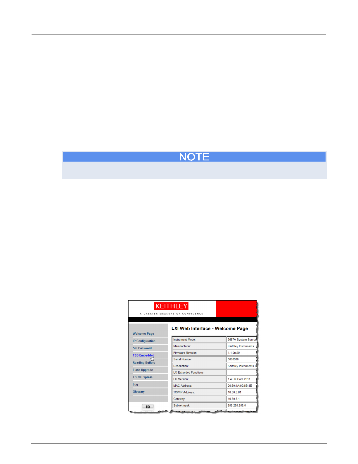
Web interface home page
The Welcome page of the web interface gives you basic information about the instrument, including:
• The instrument model, serial number, firmware revision, calibration date, and LXI information
• An ID button to help you locate the instrument
• Links to the instrument web options, including TSB Embedded, Reading Buffers, Flash Upgrade,
4-2 2657A-900-01 Rev. A / April 2012
and TSP
®
Express.
Page 29

Mo
Using the web interface
del 2657A High Power System Sourcemeter® Instrument User's Manual Section 4:
IP configuration tab
The IP Configuration tab provides access to the Model 2657A LAN settings. Refer to the Model
2657A Reference Manual for additional information about IP configuration.
You must reload the page if you change the LAN settings from the Modify IP configuration page. If the
IP address changes (due to automatic configuration mode or changing the setting to a different static
IP address), you must type the new IP address in the address bar of your Internet browser before you
can use the web interface again.
2657A-900-01 Rev. A / April 2012 4-3
Page 30
Section
User's Manual
4: Using the web interface Model 2657A High Power System Sourcemeter® Instrument
TSB Embedded
TSB Embedded is a web application that includes a command-line interface that you can use to issue
commands and interact with the instrument. TSB Embedded also provides a convenient way to
create and manage user scripts. TSB Embedded resides in the instrument.
You can use TSB Embedded to run the application examples in other sections of this manual.
If you can access the web interface home page, but cannot use TSB Embedded (or TSP Express),
make sure you have the Java
TM
SE Runtime Environment (JRE) Version 6 or later installed on your
computer.
Create a script using TSB Embedded
If you are using TSB Embedded to create scripts, you do not need to use the commands
loadscript or loadandrunscript and endscript.
Exercise: Create and run a script with TSB Embedded
The following programming example illustrates the setup and command sequence of a basic
source-measure procedure with the following parameters:
• Source function and range: voltage, autorange
• Source output level: 1000 V
• Current compliance limit: 10 mA
• Measure function and range: current, 20 mA
To create and run a sample script with TSB Embedded:
1. From the navigation on the left side of the web interface, select TSB Embedded. The TSB
Embedded page is displayed.
Figure 16: Select TSB Embedded
4-4 2657A-900-01 Rev. A / April 2012
Page 31

Model 2657A
Using the web interface
1
TSP script box
2
Script box
3
Save Script button
4
Console
5
Enter button
High Power System Sourcemeter® Instrument User's Manual Section 4:
2. To create the example script, in the TSP Script box, enter the name of the TSP script,
basic_source_measure.
Figure 17: TSB Embedded page
Item Description
2657A-900-01 Rev. A / April 2012 4-5
Page 32
Section
User's Manual
4: Using the web interface Model 2657A High Power System Sourcemeter® Instrument
3. Enter the code below in the script box.
-- Restore Model 2657A defaults.
smua.reset()
-- Select voltage source function.
smua.source.func = smua.OUTPUT_DCVOLTS
-- Set source range to auto.
smua.source.autorangev = smua.AUTORANGE_ON
-- Set voltage source to 100 V.
smua.source.levelv = 100
-- Set current limit to 20 mA.
smua.source.limiti = 20e-3
-- Set current range to 20 mA.
smua.measure.rangei = 20e-3
-- Turn on output.
smua.source.output = smua.OUTPUT_ON
-- Print and place current reading in buffer.
print(smua.measure.i(smua.nvbuffer1))
-- Turn off output.
smua.source.output = smua.OUTPUT_OFF
-- Beep.
beeper.enable = beeper.ON
beeper.beep(1, 1200)
beeper.enable = beeper.OFF
Commands and parameters for the Model 2657A are case-sensitive. It is important to type in the
commands exactly as shown to avoid syntax and execution errors.
4. Click Save Script. The script is added to the User Scripts list on the left.
You can use standard edit functions, such as copy, cut, and paste in TSB Embedded. The standard
functions are available as both keyboard shortcuts and right-click menus.
5. Clear the buffer:
• In the console, type the following and then click Enter.
smua.nvbuffer1.clear()
• If successful, the command will appear in the Instrument Output box.
6. Set the buffer to append readings:
• In the console, type the following and then click Enter.
smua.nvbuffer1.appendmode = 1
• If successful, the command will appear in the Instrument Output box.
7. Set the buffer to collect timestamps:
• In the console, type the following and then click Enter.
smua.nvbuffer1.collecttimestamps = 1
• If successful, the command will appear in the Instrument Output box.
8. Run the script:
• Select the script in the User Scripts list.
• Click Run.
4-6 2657A-900-01 Rev. A / April 2012
Page 33

Model 2657A
Using the web interface
High Power System Sourcemeter® Instrument User's Manual Section 4:
9. The Instrument Output box displays any error messages and output from the script.
10. If no errors appear, but readings do, click Run a few times to populate the buffer. Each time the
script is run, readings appear in the Instrument Output box and are also placed in the buffer.
Script management options
Existing scripts are listed in the User Scripts box on the left side of TSB Embedded.
To run a script, click the name of the script and then click Run.
To delete a script, click the name of the script and click Delete. The script is deleted from the User
Scripts list and from the nonvolatile memory of the instrument.
To stop operation of a script, click Abort Script.
To export the selected script to the computer, click Export to PC. Choose the directory in which to
save the script and click Save. Scripts are saved to a file with the extension tsp. TSP files are native
to Test Script Builder or TSB Embedded, but they can be opened and edited in any text editor.
To import scripts from the computer, click Import from PC. Select the directory that contains the file.
You can only import files with the extension tsp.
To clear the name box and the box that contains the script, click Clear.
To view the contents of a script, type the name of a script in the TSP Script box and click View
Script.
Reading buffers
The Reading Buffers tab provides access to the Model 2657A reading buffers. The data used in this
example was created and placed in the buffer by the
Embedded (on page 4-4).
Exercise: Retrieve readings from a buffer
To retrieve readings from a populated buffer:
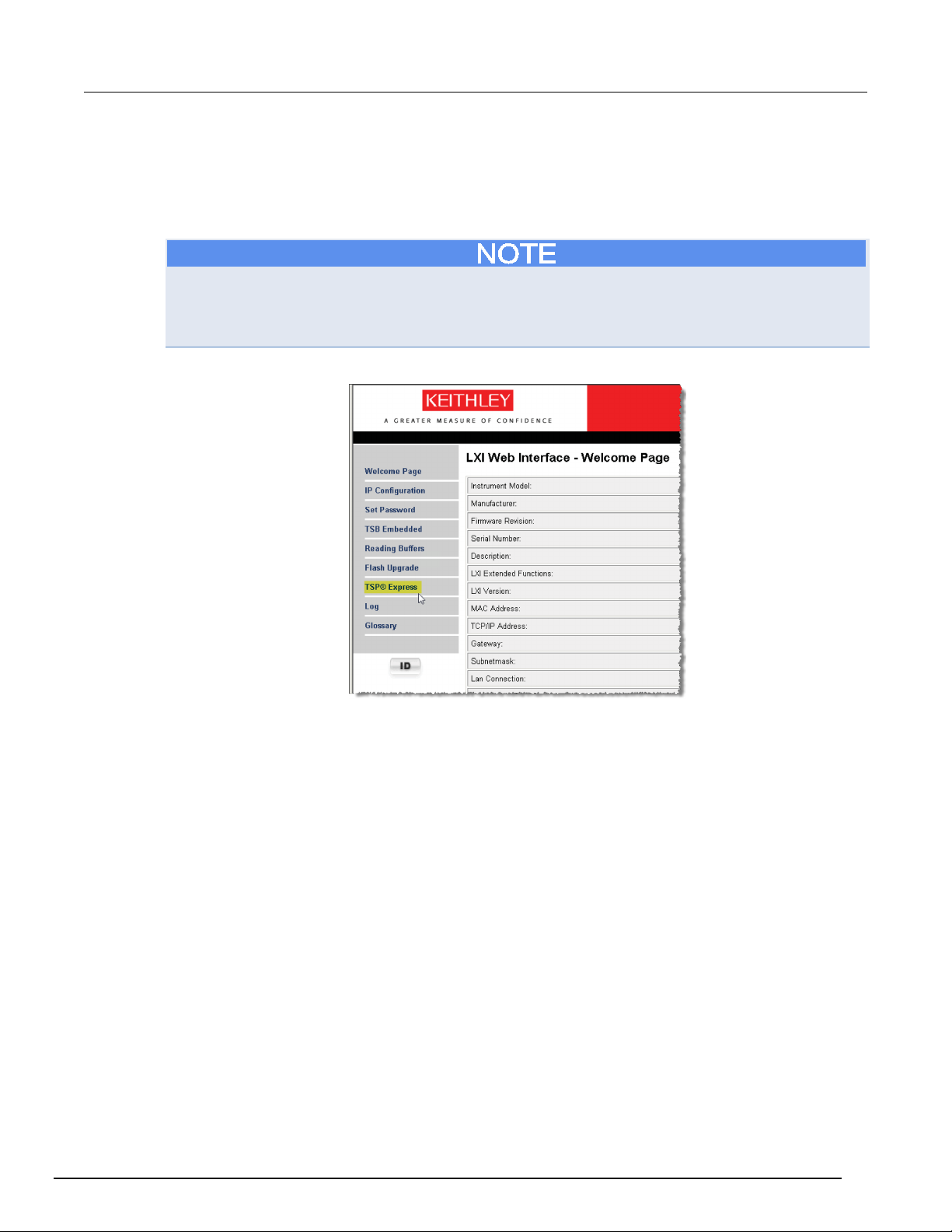
1. From the navigation area on the left side of the web interface, select Reading Buffers. The
Reading Buffers embedded page is displayed.
Exercise: Create and run a script with TSB
Figure 18: Select reading buffer
2657A-900-01 Rev. A / April 2012 4-7
Page 34
Section
User's Manual
4: Using the web interface Model 2657A High Power System Sourcemeter® Instrument
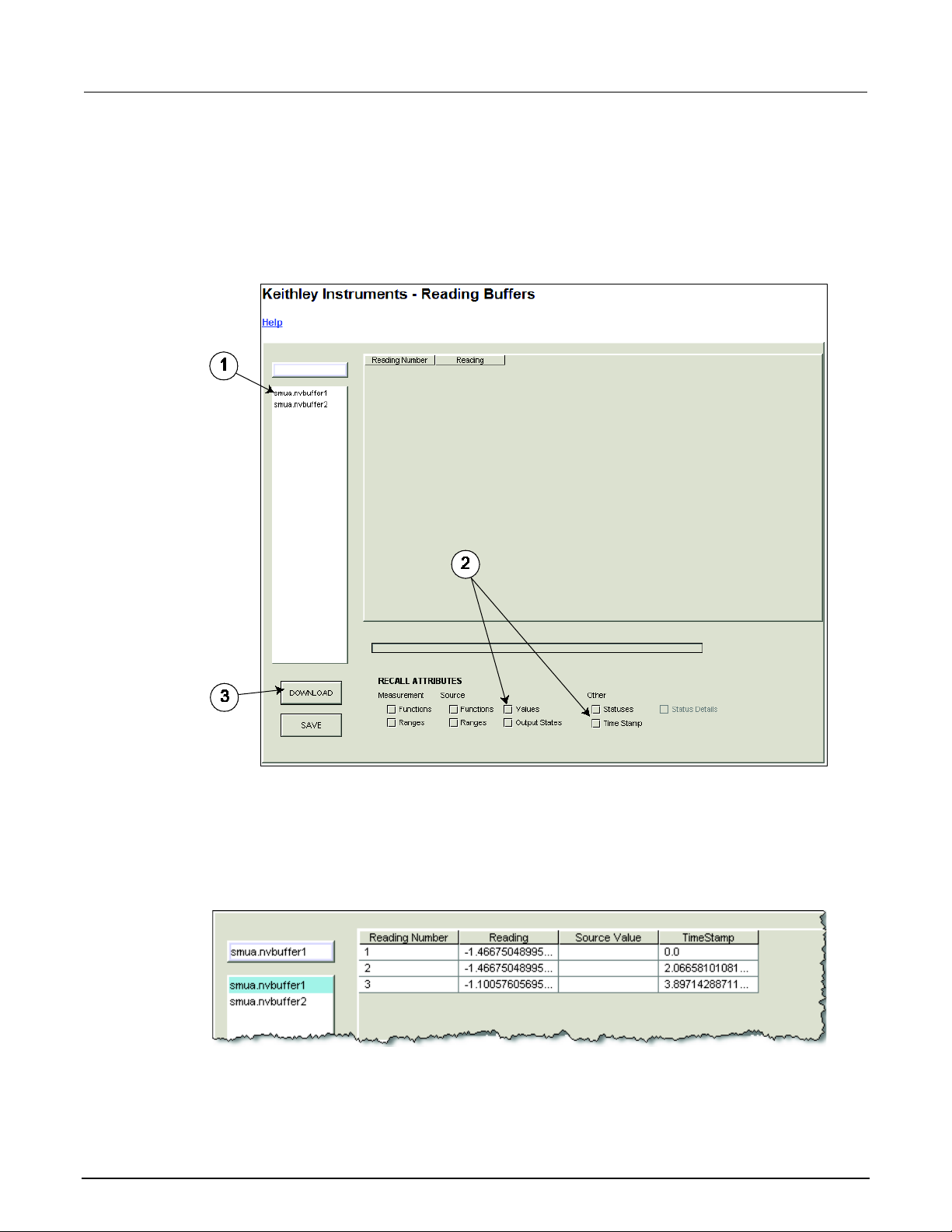
2. From the left box (1 in the following graphic), select smua.nvbuffer1.
3. In the Recall Attributes area (near the bottom of the page, shown as 2 in the following graphic),
select Values and Time Stamp.
4. Click Download (shown as 3 in the following graphic).
Figure 19: Downloading the reading buffer
5. The table displays the present buffer data. Notice that the Source Value column is not populated.
To collect source values, before taking readings, use TSB Embedded to set the following
attribute: smua.nvbuffer1.collectsourcevalues = 1.
Figure 20: Sample downloaded reading buffer
4-8 2657A-900-01 Rev. A / April 2012
Page 35
Model 2657A
Using the web interface
High Power System Sourcemeter® Instrument User's Manual Section 4:
TSP Express
The TSP® Express tab provides access to the TSP Express Launch page. From this page, click the
Launch button to start TSP Express.
Only one web application can be running and connected to the instrument at a time. TSP Express will
not run if another web application, such as TSB Embedded, Reading Buffers, or Flash Upgrade, is
running and connected to the instrument. If you need to run another web application, be sure to close
TSP Express before starting the other web application.
Figure 21: Select TSP Express
To run TSP Express:
1. From the navigation area on the left side of the web interface, select TSP Express. The TSP
Express page is displayed.
2. Click the Launch button. The TSP Express window opens.
3. There is a help pane on the right side of the TSP Express main window. You can adjust the width
of the help pane by sliding the vertical bar. Click and follow the step-by-step example in the help
pane to become familiar with TSP Express (there is a link to the example in the TSP Express
Introduction's first paragraph).
2657A-900-01 Rev. A / April 2012 4-9
Page 36

Section
User's Manual
4: Using the web interface Model 2657A High Power System Sourcemeter® Instrument
Figure 22: TSP Express
4-10 2657A-900-01 Rev. A / April 2012
Page 37

Making front-panel measurements ........................................... 5-4
In this section:
Introduction .............................................................................. 5-1
Equipment needed for this example ......................................... 5-1
Device connections .................................................................. 5-2
Introduction
You can use the Model 2657A to make basic measurements from the front panel. In this example,
measurements are made on a 100 MΩ resistor. Similar measurements can be made on any
two-terminal device under test (DUT) if appropriate source values are used.
Section 5
Making basic front-panel measurements
Equipment needed for this example
To run this example, you will need the following equipment:
• Model 2657A High Power System SourceMeter
• Additional cable and connector assemblies as required to make connections to the DUT. See
Device connections (on page 5-2
• A 100 MΩ resistor to test, enclosed in a safe test fixture such as the Keithley Instruments
Model 8010. The resistor should be rated for at least 1000 V.
• Appropriate cabling to the test fixture.
See Safe configuration and test setup (on page 2-1
) for a schematic of required connections.
®
instrument.
) for additional connection information.
Page 38

Section
User's Manual
5: Making basic front-panel measurements Model 2657A High Power System Sourcemeter® Instrument
Device connections
Connections from the Model 2657A to the DUT are shown in the illustrations on the following pages.
Proper care should be taken to ensure good contact through all connections.
The information in this topic is intended only for qualified service personnel. Some of the
procedures may expose you to hazardous voltages that could result in personal injury or
death. Do not attempt to perform these procedures unless you are qualified to do so.
Hazardous voltages may be present on all output and guard terminals. To prevent electrical
shock that could cause injury or death, never make or break connections to the Model 2657A
while the instrument is powered on. Turn off the equipment from the front panel or
disconnect the main power cord from the rear of the Model 2657A before handling cables.
Putting the equipment into standby does not guarantee that the outputs are powered off if a
hardware or software fault occurs.
Guard voltage can be hazardous. With an unguarded device under test (DUT) connection,
terminate the guard before the end of the cable. Refer to High-voltage triaxial cable
termination for details.
Connect the enclosure of all metal test fixtures to protective earth (safety ground) (see your
specific test fixture for information). Nonconductive test fixtures must be rated to double the
maximum capability of the test equipment in the system.
Figure 23: Connections for basic front-panel measurement application
5-2 2657A-900-01 Rev. A / April 2012
Page 39

Model 2657A
surements
1
Model 2657A protective earth (safety
1
Additional connections for redundant protective
protective earth (safety ground) cable assembly.
2
Interlock connection
1
Model 2657A digital I/O; pin 24 (INT) and pin 22
connection
4
Interlocked metal safety enclosure
1
A safety enclosure with an interlock that has a
normally-open (NO) switch.
5
Test fixture protective earth (safety
ground)
1
Redundant grounds may be required for specific
test setups.
6
Model HV-CA-571-3 High-Voltage
Unterminated Cable Assembly
2
See Using high-voltage triaxial connectors (on
Triaxial Cable
8
Model 2657A
1
High Power System Sourcemeter® Instrument User's Manual Section 5: Making basic front-panel mea
Item Description Qty Notes
ground)
earth may be required.
Keithley Instrument's Model CA-568 is a
(5 VDC) connected to the test fixture lid switch.
Keithley Instrument's Model 7709-308 is a 25-pin
interlock male connector that can be used for
custom connections.
Interlock switch is shown in the disengaged (lid
open) position.
3 Test fixture interlock switch
Triaxial Panel-Mount Connector to
7 Model HV-CA-554 High-Voltage
1
page 2-7) for detail.
2
Figure 24: Physical connections for basic front-panel measurement application
2657A-900-01 Rev. A / April 2012 5-3
Page 40

Section
User's Manual
5: Making basic front-panel measurements Model 2657A High Power System Sourcemeter® Instrument
Making front-panel measurements
Use the following procedure to configure the instrument and make measurements from the front
panel.
If you see error code 802, "OUTPUT blocked by interlock," the interlock is not engaged. To recover
from this error, properly engage the interlock using a safe test fixture, and then turn on the Model
2657A output.
Procedure for making front-panel measurements
Step 1: Select and set source level
Perform the following steps to select the voltage source and set its value to 1000 V:
1. Press the SRC key as needed to select the V-Source, as indicated by the units in the source field
on the display. The flashing digit (cursor) indicates which value is selected for editing.
2. Move the cursor to the digit to change, then press the navigation wheel
mode, as indicated by the EDIT indicator.
3. Use the RANGE keys to select the 1500 V range. If using a different source value, use the lowest
possible range for the best accuracy.
4. Set the source value to 1000.00 V, and then press the ENTER key or the navigation wheel
complete editing.
Step 2: Set compliance limit
Perform the following steps to edit the compliance limit value to 100 µA:
1. Press the LIMIT key.
2. Move the cursor to the digit to change, then press the navigation wheel
mode, as indicated by the EDIT indicator.
3. Enter the limit value of 100.00 µA.
4. Press the ENTER key or the navigation wheel
to complete editing.
to enter the EDIT
to
to enter the EDIT
Step 3: Select measurement function and range
To select measurement function and range:
1. Select the current measurement function by pressing the MEAS key as needed.
2. Enable autorange by pressing the AUTO key (the AUTO indicator lights). Alternatively, you can
set manual ranging using the up or down RANGE keys.
Step 4: Turn output on
5-4 2657A-900-01 Rev. A / April 2012
Turn the output on by pressing the OUTPUT ON/OFF control. The OUTPUT indicator light turns on.
Page 41

Model 2657A
panel measurements
High Power System Sourcemeter® Instrument User's Manual Section 5: Making basic front-
Step 5: Observe readings on the display
Observe the readings on the display. Press the TRIG key if necessary to trigger the instrument to
begin taking readings. The readings are on the top line, and source and limit values are on the
bottom line. For the 100 MΩ resistor, typical display values are:
10.0000uA
SrcA: +1000.00V LimA:100.000uA
1. Press the MEAS key several times to display measured voltage, resistance, power, and current.
Typical values for the 100 MΩ resistor are
1000.00 V, 100.000 MOhm, 10.000 mW, and 10.0000 uA.
Step 6: Turn output off
When finished, turn the output off by pressing the OUTPUT ON/OFF control. The OUTPUT indicator
light will turn off.
2657A-900-01 Rev. A / April 2012 5-5
Page 42

Page 43

Advanced reverse voltage sweep ............................................ 6-9
In this section:
Introduction .............................................................................. 6-1
Equipment required .................................................................. 6-1
Set up communication .............................................................. 6-2
Device connections .................................................................. 6-3
Simple reverse voltage sweep ................................................. 6-5
Introduction
This example demonstrates how to use the Model 2657A to measure the reverse breakdown
characteristics of a high-voltage diode. The Model 2657A measures the leakage current as the
reverse voltage is swept to the specified breakdown voltage of the diode.
Section 6
Measuring diode off-state breakdown
There are two examples in this section. The first example demonstrates the simplest method. This
method configures a sweep using a programmatic "for" loop.
The second example demonstrates a more advanced method for configuring this measurement by
using the Model 2657A trigger model to run the sweep. This method is useful in the following
situations:
• If you require very precise timing either for source or measurement.
• If you are using a Model 2657A in a multi-instrument setup and you need to receive or output
trigger signals to other instruments or device handlers.
Equipment required
Equipment required:
• One Model 2657A High Power System SourceMeter
• One GPIB or Ethernet cable to connect the Model 2657A to a computer
• One high voltage diode enclosed in a safe test fixture, such as the Keithley Instruments
Model 8010 High Power Test Fixture Device
• Appropriate cabling to connect the Model 2657A to the test fixture
®
Instrument
Page 44

Section
User's Manual
1
IEEE-488 connection
1
GPIB. Model 2657A is IEEE Std 488.1 compliant.
2
LAN connection
1
Model 2657A is LXI version 1.4 Core 2011
Model CA-180-3 LAN Crossover Cable.
3
RS-232 connection
1
Serial communication port.
6: Measuring diode off-state breakdown Model 2657A High Power System Sourcemeter® Instrument
Set up communication
The communication setup is illustrated in the following figure. This application can be run using any of
the supported communication interfaces for the instrument.
For additional detail about remote communications, see "Communications interfaces" in the
Model 2657A Reference Manual.
Item Description Qty Notes
Figure 25: Communication connections
compliant. It supports TCP/IP and complies with
IEEE Std 802.3 (ethernet). 10 or 100 Mbps.
This is available from Keithley Instruments; see
6-2 2657A-900-01 Rev. A / April 2012
Page 45

Model 2657A
state breakdown
High Power System Sourcemeter® Instrument User's Manual Section 6: Measuring diode off-
Device connections
Refer to the following figure to connect the diode in a safe test fixture.
See Safe configuration and test setup (on page 2-1
2657A to a device under test (DUT).
Figure 26: Two-wire diode connections
) for information on safely connecting the Model
2657A-900-01 Rev. A / April 2012 6-3
Page 46

Section
User's Manual
earth (safety ground) cable assembly.
2
Interlock connection
1
Model 2657A digital I/O; pin 24 (INT) and pin 22
open) position.
3
Test fixture interlock switch connection
1
4
Interlocked metal safety enclosure
1
A safety enclosure with an interlock that has a
normally-open (NO) switch.
ground)
test setups.
6
Model HV-CA-571-3 High-Voltage
Unterminated Cable Assembly
2
See Using high-voltage triaxial connectors (on
7
Model HV-CA-554 High-Voltage Triaxial
Cable
2
8
Model 2657A
1
9
Panel-mount SHV connectors
2
Customer supplied.
10
Model SHV-CA-553 High-Voltage
Triaxial to SHV Cable
2
6: Measuring diode off-state breakdown Model 2657A High Power System Sourcemeter® Instrument
Item Description Qty Notes
1 Model 2657A protective earth (safety
ground)
1 Additional connections for redundant protective
earth may be required.
Keithley Instrument's Model CA-568 is a protective
(5 VDC) connected to the test fixture lid switch.
Keithley Instrument's Model 7709-308 is a 25-pin
interlock male connector that can be used for
custom connections.
Interlock switch is shown in the disengaged (lid
5 Test fixture protective earth (safety
Triaxial Panel-Mount Connector to
Redundant grounds may be required for specific
page 2-7).
If you are using a Model 8010 High Power Test Fixture, see the Interconnect Reference Guide
drawing "Two-terminal axial DUT with a Model 2657A connected" for connections and the Model
8010 User's Manual drawing "Model 2657A connections."
Figure 27: Two-wire diode physical connections
6-4 2657A-900-01 Rev. A / April 2012
Page 47

Model 2657A
state breakdown
High Power System Sourcemeter® Instrument User's Manual Section 6: Measuring diode off-
Simple reverse voltage sweep
The example code is designed to be run from Test Script Builder or TSB Embedded. It can also be
run from other programming environments, such as Microsoft® Visual Studio® or National Instruments
LabVIEWTM. However, you may need to make changes to the example code to use other
programming environments.
This example demonstrates a simple method that you can use to configure and execute a reverse
voltage sweep on a diode and collect current measurements.
This example uses a Test Script Processor (TSP
includes two separate functions that configure the System SourceMeter Instrument and return the raw
current and voltage readings that are stored in the reading buffer.
®
) script to perform the measurement. The script
The script is written using Test Script Processor (TSP) functions rather than as a single block of inline
code. TSP functions are similar to functions in other programming languages, such as Microsoft
Visual C
®
or Visual Basic®. They must be called before the code in them is executed. Because of this,
®
running the script alone will not execute the test. To execute the test, you need to run the script to
load the functions into test script memory. You then call the functions.
Refer to the documentation for Test Script Builder or TSB Embedded (on page 4-4
) for directions on
how to run scripts and enter commands using the instrument console.
Example code
--[[
DiodeRL(vstart, vstop, vstep, irange, ilimit)
Description: This function uses a "for" loop to configure a
reverse voltage sweep on a diode and collect leakage current
measurements.
This demonstrates a very simple method of performing a linear
voltage sweep on the Model 2657A.
Parameters:
vstart: The starting voltage of the diode reverse voltage sweep.
vstop: The stopping voltage of the diode reverse voltage sweep.
vstep: The step voltage of the diode reverse voltage sweep
(how much the voltage changes per step).
irange: current measurement range, set to a value or set to
"auto" to enable autorange.
ilimit: The current limit of the voltage source.
2657A-900-01 Rev. A / April 2012 6-5
Page 48

Section
User's Manual
6: Measuring diode off-state breakdown Model 2657A High Power System Sourcemeter® Instrument
Additional notes:
Source delay is automatically added to each point of this sweep
because the smua.source.levelv command is used.
Source delay varies by voltage range.
If the timing of the source is critical to your application,
please use the DiodeRL_Swp function instead.
Example usage:
DiodeRL(0, 1000, 100, 100e-9, 0.01)
--]]
function DiodeRL(vstart,vstop,vstep,irange,ilimit)
--Reset and initialize instrument.
reset()
status.reset()
errorqueue.clear()
--Configure source function as 2W DCVOLTS.
smua.source.func = smua.OUTPUT_DCVOLTS
smua.sense = smua.SENSE_LOCAL
--Define local variable to store the number of points in the sweep.
local l_numPoints
--[[
Calculate the number of points based on the start and
stop values of the sweep.
--]]
if math.abs(vstart) > math.abs(vstop) then
smua.source.rangev = vstart
l_numPoints = (vstart - vstop) / vstep + 1
else
smua.source.rangev = vstop
l_numPoints = (vstop - vstart) / vstep + 1
end
--Set up current compliance.
smua.source.limiti = ilimit
--Sets up current range.
if irange == "auto" then
smua.measure.autorangei = smua.AUTORANGE_ON
else
smua.measure.autorangei = smua.AUTORANGE_OFF
smua.measure.rangei = irange
end
--Set the measurement integration time.
smua.measure.nplc = 1
smua.measure.delay = 0.05
6-6 2657A-900-01 Rev. A / April 2012
Page 49

Model 2657A
state breakdown
High Power System Sourcemeter® Instrument User's Manual Section 6: Measuring diode off-
--Configure the reading buffers.
smua.nvbuffer1.clear()
smua.nvbuffer1.appendmode = 1
smua.nvbuffer1.collecttimestamps = 1
smua.nvbuffer1.collectsourcevalues = 0
smua.nvbuffer1.fillmode = smua.FILL_ONCE
smua.nvbuffer2.clear()
smua.nvbuffer2.appendmode = 1
smua.nvbuffer2.collecttimestamps = 1
smua.nvbuffer2.collectsourcevalues = 0
smua.nvbuffer2.fillmode = smua.FILL_ONCE
--Define local variable for index of the "for" loop.
local l_i
--Turn on the output.
smua.source.output = 1
--[[
Use a "for" loop to run the linear voltage sweep and
make current and voltage measurements.
--]]
for l_i = 0, (l_numPoints-1) do
--Update the source level.
smua.source.levelv = vstart + l_i*(vstep)
--Make simultaneous voltage and current measurements.
smua.measure.iv(smua.nvbuffer1, smua.nvbuffer2)
end
--Set the voltage level back to 0 V.
smua.source.levelv = 0
--Turn off the output.
smua.source.output = 0
end
--[[
This function prints the data from the smua.nvbuffer1 and
smua.nvbuffer2 reading buffers into three separate
tab-delimited columns.
--]]
function printData()
if smua.nvbuffer1.n == 0 then
print("No readings in buffer")
else
print("Timestamps\tCurrent\tVoltage")
for i = 1, smua.nvbuffer1.n do
print(string.format("%g\t%g\t%g", smua.nvbuffer1.timestamps[i],
smua.nvbuffer1.readings[i], smua.nvbuffer2.readings[i]))
end
end
end
2657A-900-01 Rev. A / April 2012 6-7
Page 50
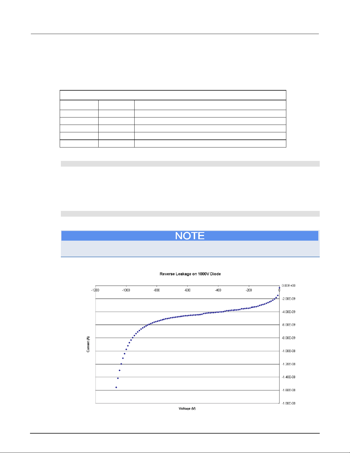
Section
User's Manual
vstart
volts
Start voltage for the linear voltage sweep
vstop
volts
Stop voltage for the linear voltage sweep
vstep
volts
Step voltage for the sweep
irange
current
Current measurement range
ilimit
current
Current limit (compliance)
6: Measuring diode off-state breakdown Model 2657A High Power System Sourcemeter® Instrument
Example usage
The functions in this script allow updates to the test parameters without rewriting or re-running the
script. To run the test, call the DiodeRL() function, passing in the appropriate values for test
parameters.
DiodeRL() parameters
Parameter Units Description
An example of how to call this function is shown here:
DiodeRL(0, 1000, 10, 100e-9, 0.01)
This call results in a 101-point linear voltage sweep starting at 0 V and proceeding to 1000 V in 10 V
increments. The current measurement range is set to 100 nA and the current limit is set to 10 mA.
You can use the printData() function to return the stored voltage and current measurements and
the timestamps. The data is formatted into three columns. Here is an example of how to call the
printData() function:
printData()
An example of the output is shown here.
The connections that were made to the device were set up so that when a positive voltage was
sourced, the device was reverse biased. The voltage readings were negated before graphing.
Figure 28: Results of sample data for diode breakdown characteristics
6-8 2657A-900-01 Rev. A / April 2012
Page 51

Model 2657A
state breakdown
High Power System Sourcemeter® Instrument User's Manual Section 6: Measuring diode off-
Advanced reverse voltage sweep
This example demonstrates how to use the trigger model of the Model 2657A to perform a reverse
linear voltage sweep on a diode and collect current measurements. The trigger model is useful when
critical timing is required or when the Model 2657A must send or receive triggers from an external
instrument or device handler.
This example does not configure any incoming or outgoing trigger signals. For more information on
the trigger model, see the Model 2657A Reference Manual.
Example code
--[[
DiodeRL_Swp(vstart, vstop, vstep, irange, ilimit, sourceDelay)
Description: This function uses the trigger model and built-in
sweeping function to create a linear voltage sweep to measure
the reverse leakage of a diode.
Using this method is useful when there is a need to send or
receive external triggers from another instrument or
device handler.
Parameters:
vstart: The starting voltage of the diode reverse voltage sweep.
vstop: The stopping voltage of the diode reverse voltage sweep.
vstep: The step voltage of the diode reverse voltage sweep
(how much the voltage changes per step).
irange: current measurement range, set to value or set to "auto"
to enable autorange.
ilimit: The current limit of the voltage source.
sourceDelay: The delay between the start of source and the
source complete event.
Example usage:
DiodeRL_Swp(0, 1000, 10, 100e-9, 0.01, 0.05)
--]]
function DiodeRL_Swp(vstart,vstop,vstep,irange,ilimit,sourceDelay)
--Reset and initialize instrument.
reset()
status.reset()
errorqueue.clear()
--Configure source function as 2W DCVOLTS
smua.source.func = smua.OUTPUT_DCVOLTS
smua.sense = smua.SENSE_LOCAL
--Define a local variable to store the number of points in the sweep.
local l_numPoints
2657A-900-01 Rev. A / April 2012 6-9
Page 52

Section
al
6: Measuring diode off-state breakdown Model 2657A High Power System Sourcemeter® Instrument User's Manu
--[[
Calculate the number of points in the sweep based on the
start and stop values.
--]]
if math.abs(vstart) > math.abs(vstop) then
smua.source.rangev = vstart
else
smua.source.rangev = vstop
end
l_numPoints = math.abs((vstop - vstart) / vstep) + 1
--Set up source delay.
smua.source.delay = sourceDelay
--Set up current compliance.
smua.source.limiti = ilimit
--Set up current measurement range.
if irange == "auto" then
smua.measure.autorangei = smua.AUTORANGE_ON
else
smua.measure.autorangei = smua.AUTORANGE_OFF
smua.measure.rangei = irange
end
--Set the integration time.
smua.measure.nplc = 1
--Configure the reading buffers.
smua.nvbuffer1.clear()
smua.nvbuffer1.appendmode = 0
smua.nvbuffer1.collecttimestamps = 1
smua.nvbuffer1.collectsourcevalues = 0
smua.nvbuffer1.fillmode = smua.FILL_ONCE
smua.nvbuffer2.clear()
smua.nvbuffer2.appendmode = 0
smua.nvbuffer2.collecttimestamps = 1
smua.nvbuffer2.collectsourcevalues = 0
smua.nvbuffer2.fillmode = smua.FILL_ONCE
--Configure the source sweep.
smua.trigger.source.linearv(vstart, vstop,l_numPoints)
smua.trigger.source.action = smua.ENABLE
smua.trigger.source.stimulus = 0
--Configure measurements during the sweep.
smua.trigger.measure.action = smua.ENABLE
smua.trigger.measure.stimulus = 0
smua.trigger.measure.iv(smua.nvbuffer1,smua.nvbuffer2)
--Configure trigger model parameters.
smua.trigger.count = l_numPoints
smua.trigger.arm.count = 1
--Turn on the output.
smua.source.output = 1
6-10 2657A-900-01 Rev. A / April 2012
Page 53

Model 2657A
state breakdown
High Power System Sourcemeter® Instrument User's Manual Section 6: Measuring diode off-
--[[
Initiate the sweep and wait until sweep is complete before
proceeding to next command.
--]]
smua.trigger.initiate()
waitcomplete()
--Turn off the output.
smua.source.output = 0
end
--[[
This function prints the data from the smua.nvbuffer1 and
smua.nvbuffer2 reading buffers into three separate columns.
--]]
function printData()
if smua.nvbuffer1.n == 0 then
print("No readings in buffer")
else
print("Timestamps\tCurrent\tVoltage")
for i = 1, smua.nvbuffer1.n do
print(string.format("%g\t%g\t%g",
smua.nvbuffer1.timestamps[i], smua.nvbuffer1.readings[i],
smua.nvbuffer2.readings[i]))
end
end
end
2657A-900-01 Rev. A / April 2012 6-11
Page 54

Section
User's Manual
vstart
volts
Start voltage for the linear voltage sweep
vstop
volts
Stop voltage for the linear voltage sweep
vstep
volts
Step voltage for the sweep
irange
current
Current measurement range
ilimit
current
Current limit (compliance)
sourceDelay
seconds
The delay between the source complete event and
the start of the measurement
6: Measuring diode off-state breakdown Model 2657A High Power System Sourcemeter® Instrument
Example usage
The functions in this script allow updates to the test parameters without rewriting or re-running the
script. To run the test, call the DiodeRL_Swp() function, passing in the appropriate values for test
parameters.
DiodeRL_Swp() parameters
Parameter Units Description
An example of how to call this function is shown here:
DiodeRL_Swp(0, 1000, 10, 100e-9, 0.01, 0.05)
This call results in a 101-point linear voltage sweep starting at 0 V and proceeding to 1000 V in 10 V
increments. The current measurement range is set to 100 nA and the current limit is set to 10 mA.
A 50 ms delay occurs after each source step is programmed. The source complete event of the
trigger model is held off until that delay is complete. Once the delay, and therefore the source event,
is complete, the measure action can take place.
For more information on the trigger model, please see the Model 2657A Reference Guide.
You can use the printData() function to return the stored voltage and current measurements and
the timestamps. The data is formatted into three columns. An example of how to call the
printData() function is:
printData()
The results of this test are the same as those produced by the simple reverse voltage sweep. See
Simple reverse voltage sweep (on page 6-5
) for a graph of the results.
6-12 2657A-900-01 Rev. A / April 2012
Page 55

Measuring leakage current and insulation resistance .............. 7-4
In this section:
Introduction .............................................................................. 7-1
Equipment required .................................................................. 7-1
Set up communication .............................................................. 7-2
Device connections .................................................................. 7-2
Introduction
This example demonstrates how to use the Model 2657A High Power System SourceMeter®
Instrument to measure the leakage current and calculate the insulation resistance of a capacitor.
Section 7
Measuring capacitor leakage
In this example:
1. The capacitor is charged to the desired voltage.
2. The voltage is held across the capacitor for a user-specified amount of time.
3. The current is measured.
4. The Model 2657A discharges the capacitor using the programmed current limit.
Equipment required
Equipment required:
• One Model 2657A High Power System SourceMeter
• One GPIB or Ethernet cable to connect the Model 2657A to a computer
• One high voltage capacitor enclosed in a safe test fixture, such as the Keithley Instruments
Model 8010
• Appropriate cabling to connect the Model 2657A to the test fixture
®
Instrument
Page 56

Section
User's Manual
1
IEEE-488 connection
1
GPIB. Model 2657A is IEEE Std 488.1 compliant.
2
LAN connection
1
Model 2657A is LXI version 1.4 Core 2011
Model CA-180-3 LAN Crossover Cable.
3
RS-232 connection
1
Serial communication port.
7: Measuring capacitor leakage Model 2657A High Power System Sourcemeter® Instrument
Set up communication
The communication setup is illustrated in the following figure. This application can be run using any of
the supported communication interfaces for the instrument.
For additional detail about remote communications, see "Communications interfaces" in the Model
2657A Reference Manual.
Item Description Qty Notes
Figure 29: Communication connections
Device connections
Refer to the following figure to connect the capacitor in a safe test fixture.
See Safe configuration and test setup (on page 2-1
2657A to a device under test (DUT).
For connections if you are using a Model 8010 High Power Test Fixture, see the Interconnect
Reference Guide drawing "Two-terminal axial DUT with a Model 2657A connected" and the Model
8010 User's Manual drawing "Model 2657A connections."
compliant. It supports TCP/IP and complies with
IEEE Std 802.3 (ethernet). 10 or 100 Mbps.
This is available from Keithley Instruments; see
) for information on safely connecting the Model
7-2 2657A-900-01 Rev. A / April 2012
Page 57

Model 2657A
Measuring capacitor leakage
earth (safety ground) cable assembly.
interlock male connector that can be used for custom
pen)
position.
3
Test fixture interlock switch
connection
1
4
Interlocked metal safety enclosure
1
A safety enclosure with an interlock that has a
normally-open (NO) switch.
5
Test fixture protective earth (safety
ground)
1
Additional connections for redundant grounds may
be required for specific test setups.
6
Model HV-CA-571-3 High-Voltage
2
See Using high-voltage triaxial connectors (on page
Triaxial Cable
8
Model 2657A
1 9
Panel-mount SHV connectors
2
Customer-supplied.
10
Model SHV-CA-553 High-Voltage
Triaxial to SHV Cable
2
High Power System Sourcemeter® Instrument User's Manual Section 7:
Figure 30: Two-wire capacitor connections
Item Description Qty Notes
1 Model 2657A protective earth (safety
ground)
2 Interlock connection 1 Model 2657A digital I/O; pin 24 (INT) and pin 22
Triaxial Panel-Mount Connector to
Unterminated Cable Assembly
7 Model HV-CA-554 High-Voltage
1 Additional connections for redundant protective earth
may be required.
Keithley Instrument's Model CA-568 is a protective
(5 VDC) connected to the test fixture lid switch.
Keithley Instrument's Model 7709-308 is a 25-pin
connections.
Interlock switch is shown in the disengaged (lid o
2-7).
4
2657A-900-01 Rev. A / April 2012 7-3
Page 58

Section
User's Manual
7: Measuring capacitor leakage Model 2657A High Power System Sourcemeter® Instrument
Figure 31: Two-wire capacitor physical connections
Measuring leakage current and insulation resistance
The example code is designed to be run from Test Script Builder or TSB Embedded. It can also be
run from other programming environments, such as Microsoft® Visual Studio® or National Instruments
LabVIEWTM. However, you may need to make changes to the example code to use other
programming environments.
This example demonstrates a simple method for measuring the leakage current and insulation
resistance of a capacitor. This example uses a TSP script to perform the measurement. The script
includes two separate functions for configuring the System SourceMeter Instrument and returning the
raw current and voltage readings from the reading buffer.
The script is written using TSP functions rather than as a single block of inline code. TSP functions
are similar to functions in other programming languages, such as Microsoft
®
. They must be called before the code in them is executed. Because of this, running the script
Basic
alone will not execute the test. To execute the test, you need to run the script to load the functions
into test script memory. You then call the functions.
Refer to the documentation for Test Script Builder or TSB Embedded for directions on how to run
scripts and enter commands using the instrument console.
®
Visual C® or Visual
Example code
function runCapLeak(testV, iLimit, measRange, numReadings, soakTime, numNPLC)
--Initialize SMU.
reset()
errorqueue.clear()
status.reset()
7-4 2657A-900-01 Rev. A / April 2012
Page 59

Model 2657A
Measuring capacitor leakage
High Power System Sourcemeter® Instrument User's Manual Section 7:
--Configure reading buffers.
smua.nvbuffer1.clear()
smua.nvbuffer1.appendmode = 0
smua.nvbuffer1.collecttimestamps = 1
smua.nvbuffer1.collectsourcevalues = 0
smua.nvbuffer2.clear()
smua.nvbuffer2.appendmode = 0
smua.nvbuffer2.collecttimestamps = 1
smua.nvbuffer2.collectsourcevalues = 0
--Configure source function.
smua.source.func = smua.OUTPUT_DCVOLTS
smua.source.levelv = testV
smua.source.limiti = iLimit
--[[
Configure measurement parameters. Each call of the measurement function
will result in the number of readings specified by smua.measure.count.
The time specified by smua.measure.delay is enforced before any
measurements are made.
--]]
smua.measure.autozero = smua.AUTOZERO_ONCE
smua.measure.rangei = measRange
smua.measure.count = numReadings
smua.measure.nplc = numNPLC
smua.measure.delay = soakTime
--[[
Run the test.
Turn on the output. The programmed voltage is output immediately.
--]]
smua.source.output = 1
--[[
Perform a set of current and voltage measurements. Measure delay is enforced before
measurements are made.
--]]
smua.measure.iv(smua.nvbuffer1, smua.nvbuffer2)
--[[
After measurements are complete, return the voltage to 0 V. The rate of discharge
is limited by programmed current limit.
--]]
smua.source.levelv = 0
--[[
Wait until the capacitor is fully discharged before turning off
the output.
--]]
delay(soakTime)
smua.source.output = 0
end
2657A-900-01 Rev. A / April 2012 7-5
Page 60

Section
User's Manual
testV
volts
The voltage level to test the capacitor with.
iLimit
amps
Current limit (compliance) for the test. This limits the rate of
charge and discharge of the capacitor
measRange
amps
Current measurement range to be used for leakage current
measurement.
numReadings
not
The number of measurements to make after the soak time
mean value.
soakTime
seconds
Amount of time to apply the voltage before taking a measurement.
numNPLC
not
applicable
Integration time, specified as the number of power line cycles.
7: Measuring capacitor leakage Model 2657A High Power System Sourcemeter® Instrument
--[[
This function prints the raw voltage and current measurements that
are stored in reading buffers smua.nvbuffer1 and smua.nvbuffer2
--]]
function printData()
--Retrieve average values of measured current and voltage.
current_stats = smua.buffer.getstats(smua.nvbuffer1)
voltage_stats = smua.buffer.getstats(smua.nvbuffer2)
current_mean = current_stats.mean
voltage_mean = voltage_stats.mean
--Calculate the insulation resistance of the capacitor.
resistance = voltage_mean/current_mean
--Print the summary of the results to the communication interface.
print(string.format("Average current: %g", current_mean))
print(string.format("Average voltage: %g", voltage_mean))
print(string.format("Insulator Resistance: %g", resistance))
if smua.nvbuffer1.n == 0 then
print("No reading in buffer")
else
print("Timestamps\tCurrent\tVoltage")
for i = 1, smua.nvbuffer1.n do
print(string.format("%g\t%g\t%g", smua.nvbuffer1.timestamps[i],
smua.nvbuffer1.readings[i], smua.nvbuffer2.readings[i]))
end
end
end
Example usage
The functions in this script allow updates to the test parameters without rewriting or re-running the
script. To run the test, call the runCapLeak() function, passing in the appropriate values for test
parameters.
runCapLeak() parameters
Parameter Units Description
applicable
elapses; this is the number of readings used to calculate the
7-6 2657A-900-01 Rev. A / April 2012
Page 61

Model 2657A
Measuring capacitor leakage
High Power System Sourcemeter® Instrument User's Manual Section 7:
An example of how to call this function is as follows:
runCapLeak(2000, 1e-3, 10e-9, 10, 30, 1)
This call results in the charge of the capacitor under test to 2000 V. The rate of charge of the
capacitor is limited by the 1 mA current limit. The soak time starts after the voltage source is
programmed and elapses after 30 seconds. Once the soak time has completed, 10 current
measurements are made on the 10 nA range at a 1 PLC integration rate. After all measurements are
complete, the voltage source is again programmed to 0 V and the discharge is limited by the 1 mA
current limit. The soak time is again enforced to ensure adequate time to discharge the capacitor,
then the output is turned off.
You can use the printData() function to return the voltage and current measurements and the
timestamps that are stored in the buffer. The data is formatted into three columns. To call the
printData() function, send:
printData()
An example of the summary of results that print is:
Average current: 1.62033e-09
Average voltage: 1999.9
Insulator Resistance: 1.23426e+12
Timestamps Current Voltage
0 1.65E-09 1999.9
0.016698 1.65E-09 1999.9
0.033397 1.63E-09 1999.9
0.050095 1.62E-09 1999.9
0.066793 1.63E-09 1999.9
0.083492 1.64E-09 1999.9
0.10019 1.62E-09 1999.9
0.116889 1.59E-09 1999.9
0.133587 1.57E-09 1999.9
0.150286 1.59E-09 1999.9
Sample data is shown in the following graphics. The first graphic shows a typical capacitor leakage
curve. The second graphic shows the data that is actually returned by this example. If you were to
capture the complete current to time profile of the leakage current, the data shown in the second
graphic would occur further out on the x-axis of the first graphic.
2657A-900-01 Rev. A / April 2012 7-7
Page 62
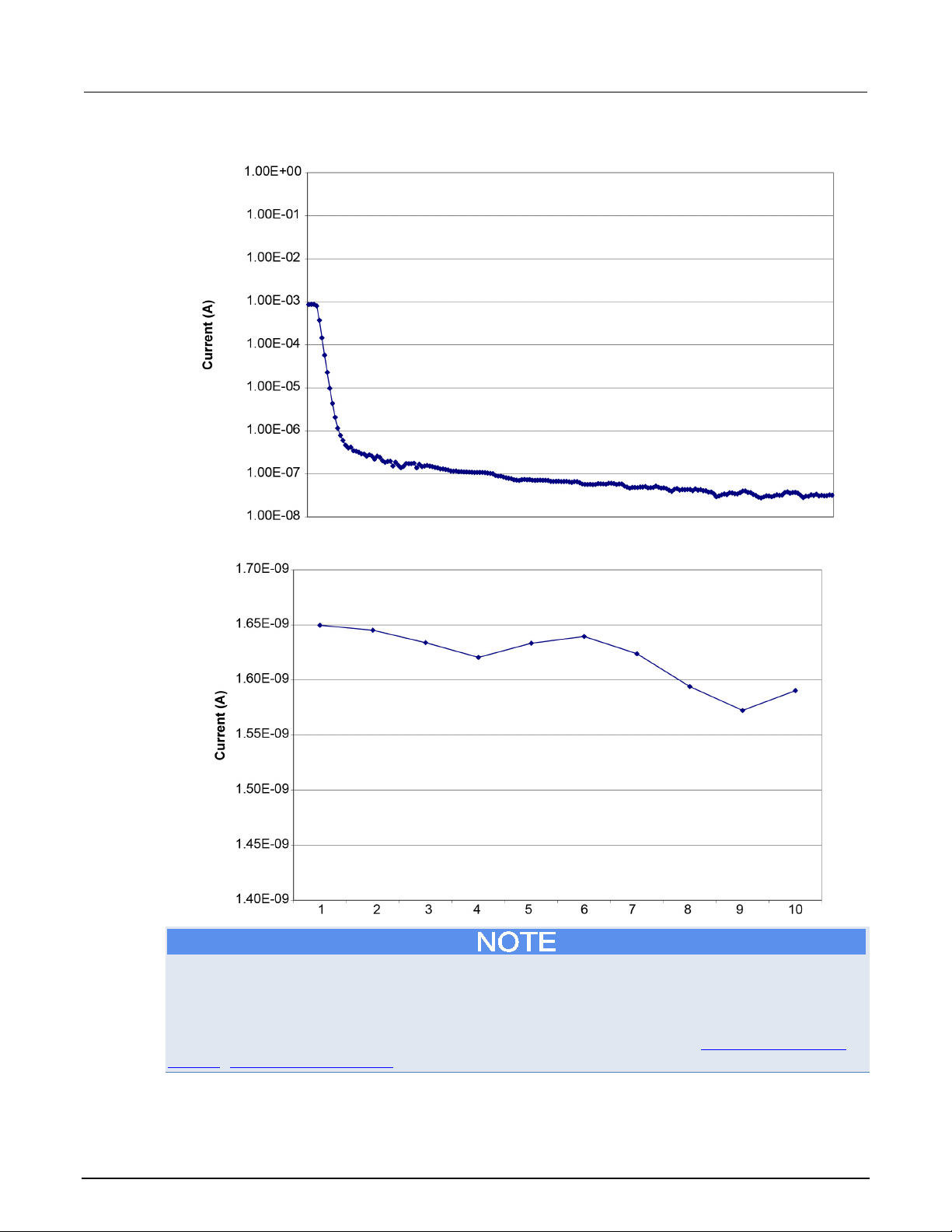
Section
User's Manual
7: Measuring capacitor leakage Model 2657A High Power System Sourcemeter® Instrument
Figure 32: Typical capacitor leakage curve
Figure 33: Sample data for capacitor leakage test
The Model 2657A voltage source is stable into capacitance values of up to 10 µF typical on the
1500 V and 3000 V ranges. See the latest Model 2657A specifications on the Keithley Instruments
website for detail. However, if noisy current measurements or voltage source oscillation occurs, try
inserting a resistor or low leakage diode in series with the capacitor. See the application note
"Capacitor Leakage Measurements with a Model 6517A Electrometer" on the Keithley Instruments
website (http://www.keithley.com) for more detail.
7-8 2657A-900-01 Rev. A / April 2012
Page 63

Idss measurement .................................................................... 8-9
In this section:
Introduction .............................................................................. 8-1
Equipment required .................................................................. 8-1
Set up communication .............................................................. 8-2
Device connections .................................................................. 8-3
BVdss measurement ................................................................ 8-6
Introduction
These examples demonstrate how to use the Model 2657A High Power System SourceMeter®
Instrument to measure drain-to-source breakdown and leakage current of a MOSFET.
Section 8
Measuring MOSFET characteristics
There are two examples in this section. The first example performs the BV
a specific current is forced from the drain to the source terminals (I
performed (V
).
ds
The second example performs the I
voltage (V
) and makes drain-current measurements with the FET in the off-state.
ds
In both examples, a second System SourceMeter Instrument is used to apply a voltage from gate to
source (V
). For n-channel, enhancement mode devices, Vgs is usually 0 V.
gs
Equipment required
Equipment required:
• One Model 2657A High Power System SourceMeter
• One Series 2600A System SourceMeter Instrument (Model 2611A, Model 2612A, Model 2635A,
or Model 2636A)
• If needed, cables to connect the Series 2600A SourceMeter Instrument to the protection module
• If needed, cables to connect the protection module to the test fixture
• If a Model 2611A or Model 2612A is being used, one Model 2600-TRIAX adapter
• If you are not using a Model 8010 High Power Device Test Fixture, you need a Model
2657A-PM-200 Protection Module to ensure that the lower voltage Series 2600A SourceMeter
Instrument is protected if the device under test fails
• One GPIB or Ethernet cable to connect the Model 2657A to a computer
• One high voltage MOSFET device enclosed in a safe test fixture, such as the Keithley
Instruments Model 8010
• Appropriate cabling to connect the Model 2657A the test fixture
measurement, in which
) and a voltage measurement is
d
measurement in which the Model 2657A sweeps the drain
dss
®
Instrument
dss
Page 64

Section
User's Manual
1
IEEE-488 connection
1
GPIB. Model 2657A is IEEE Std 488.1 compliant.
Model CA-180-3 LAN Crossover Cable.
3
RS-232 connection
1
Serial communication port.
8: Measuring MOSFET characteristics Model 2657A High Power System Sourcemeter® Instrument
Set up communication
The communication setup is illustrated in the following diagram. This application can be run using any
of the supported communication interfaces for the instruments.
For additional detail about remote communications, see "Communications interfaces" in the Model
2657A Reference Manual.
Figure 34: Remote interface and TSP-Link communications setup
Item Description Qty Notes
2 CA-180-3 1 Model 2657A is LXI version 1.4 Core 2011
compliant. It supports TCP/IP and complies with
IEEE Std 802.3 (ethernet). 10 or 100 Mbps.
This is available from Keithley Instruments; see
To set the TSP-Link node number using the front-panel interface:
1. Press the MENU key.
2. Select TSPLink.
3. Select NODE.
4. Use the navigation wheel
5. Press the ENTER key to save the TSP-Link node number.
to adjust the node number.
8-2 2657A-900-01 Rev. A / April 2012
Page 65

Model 2657A
Measuring MOSFET characteristics
High Power System Sourcemeter® Instrument User's Manual Section 8:
On the Model 2657A SMU #1 (TSP-Link node #1), perform a TSP-Link reset to update it with the
linked instruments:
1. Press the MENU key.
2. Select TSPLink.
3. Select RESET.
If error 1205 is generated during the TSP-link reset, ensure that the Series Model 2657A has a
unique TSP-Link node number.
You can also perform a TSP-Link reset from the remote command interface by sending
tsplink.reset() to the Model 2657A. This method is used in the example program.
Device connections
Refer to the following figure to connect the MOSFET in a safe test fixture.
See Safe configuration and test setup (on page 2-1
) for information on safely connecting the Model
2657A to a device under test (DUT).
If a device under test fails, high voltage may be present at a terminal to which Series 2600A
instruments are connected. This could damage a Series 2600A instrument. To prevent damage to the
Series 2600A instrument, use a Model 2657A-PM-200 Protection Module. Failure to use a protection
module could result in equipment damage.
2657A-900-01 Rev. A / April 2012 8-3
Page 66

Section
User's Manual
8: Measuring MOSFET characteristics Model 2657A High Power System Sourcemeter® Instrument
Figure 35: Schematic for measuring MOSFET characteristics application example
8-4 2657A-900-01 Rev. A / April 2012
Page 67

Model 2657A
FET characteristics
1
Model 2657A protective earth (safety
1
Additional connections for redundant protective
protective earth (safety ground) cable assembly.
2
Model 2657A interlock connection
1
Model 2657A digital I/O; pin 24 (INT) and pin 22
open) position.
3
Test fixture interlock switch
connection
1
normally-open (NO) switch.
5
Test fixture protective earth (safety
ground)
1
Redundant grounds may be required for specific
test setups.
Unterminated Cable Assembly
7
Model HV-CA-554 HV Triaxial Cable
4
8
Protective earth (safety ground) for
Module
2
The Model 2657A-PM-200 must be connected to
ground cables (Model CA-568).
9
Model 2657A-PM-200 Protection
Module
1
2636A interlock connection
DC) are connected to
the test fixture lid switch.
11
Model 7078-TRX triaxial cables
2
12
Series 2600A System SourceMeter
Model 2636A)
1
If a Model 2611A or 2612A is used, a
13
Model 2657A
1
High Power System Sourcemeter® Instrument User's Manual Section 8: Measuring MOS
Item Description Qty Notes
ground)
earth may be required.
Keithley Instrument's Model CA-568 is a
(5 VDC) connected to the test fixture lid switch.
Pin 24 and pin 19 are connected to the interlock
and digital ground on the Model 263xA.
Keithley Instrument's Model 7709-308 is a 25-pin
interlock male connector that can be used for
custom connections.
Interlock switch is shown in the disengaged (lid
4 Interlocked metal safety enclosure 1 A safety enclosure with an interlock that has a
6 Model HV-CA-571-3 High-Voltage
Triaxial Panel-Mount Connector to
the Model 2657A-PM-200 Protection
4 See Using high-voltage triaxial connectors (on
page 2-7).
protective earth using the supplied green-yellow
10 Model 2611A, 2612A, 2635A or
Instrument (Model 2611A,
Model 2612A, Model 2635A, or
If you are using a Model 8010 High Power Test Fixture, see the Interconnect Reference Guide
drawing "Three-terminal DUT with a Model 2657A. Also see the Model 8010 User's Manual for
information on how to connect the instrument to the fixture.
1 Pin 24 (INT) and pin 19 (5 V
Model 2600-TRIAX adapter is also required
2657A-900-01 Rev. A / April 2012 8-5
Page 68

Section
User's Manual
8: Measuring MOSFET characteristics Model 2657A High Power System Sourcemeter® Instrument
Figure 36: Measuring MOSFET characteristics application example connections
BVdss measurement
The example code is designed to be run from Test Script Builder or TSB Embedded. It can also be
run from other programming environments, such as Microsoft® Visual Studio® or National Instruments
LabVIEWTM. However, you may need to make changes to the example code to use other
programming environments.
This example performs the BV
source terminals and measures the resulting V
measurement. The script includes two separate functions for configuring the System SourceMeter
Instrument and returning the raw current and voltage readings from the reading buffer.
8-6 2657A-900-01 Rev. A / April 2012
measurement. The Model 2657A forces a current from the drain to
dss
. This example uses a TSP script to perform the
ds
Page 69

Model 2657A
Measuring MOSFET characteristics
High Power System Sourcemeter® Instrument User's Manual Section 8:
The script is written using Test Script Processor (TSP) functions rather than as a single block of inline
code. TSP functions are similar to functions in other programming languages, such as Microsoft
Visual C
®
or Visual Basic®. They must be called before the code in them is executed. Because of this,
running the script alone will not execute the test. To execute the test, you need to run the script to
load the functions into test script memory. You then call the functions.
Refer to the documentation for Test Script Builder or TSB Embedded (on page 4-4
) for directions on
how to run scripts and enter commands using the instrument console.
Example code
--[[
Title: FET Drain-Source Breakdown Voltage
Description: This script measures the drain-source
breakdown voltage (BVdss) of a FET.
--]]
--[[
BVdss(gateV, drainI, measDelay, igLimit, vdLimit, numNPLC)
Description: This function uses the Model 2657A to force a current
from drain to source. The SMU also measures the resulting voltage (Vds)
with the FET channel turned off. A second System SourceMeter Instrument
applies the gate to source voltage (Vgs) to ensure that the gate is
turned off.
Parameters:
gateV: Applied gate voltage (Vgs).
drainI: Test current applied by the Model 2657A from
drain to source (Id).
measDelay: Measurement delay before making the drain voltage
measurement (Vgs).
igLimit: Current limit (compliance) for the SMU connected to the
FET gate terminal.
vdLimit: Voltage limit (compliance) for the SMU connected to the
FET drain terminal.
numNPLC: Integration time for the drain voltage measurement
(in number of power line cycles).
Example usage:
BVdss(0, 0.001, 0.01, 0.01, 2000, 1)
--]]
function BVdss(gateV, drainI, measDelay, igLimit, vdLimit, numNPLC)
--Initialize SMU.
reset()
errorqueue.clear()
status.reset()
tsplink.reset()
®
2657A-900-01 Rev. A / April 2012 8-7
Page 70

Section
User's Manual
gateV
SourceMeter Instrument
drainI
amps
Drain current forced by Model 2657A
measDelay
seconds
Measurement delay after applying drain current and before
measuring BV
dss
igLimit
amps
Current limit for the Series 2600A SourceMeter Instrument
connected to the MOSFET gate terminal
vdLimit
volts
Voltage limit (compliance) for the Model 2657A connected to
the MOSFET drain terminal; should be greater than or equal
to the expected BV
dss
value
numNPLC
not applicable
Integration time, specified as the number of power line
cycles
8: Measuring MOSFET characteristics Model 2657A High Power System Sourcemeter® Instrument
--Configure source function.
node[2].smua.source.func = node[2].smua.OUTPUT_DCVOLTS
node[2].smua.source.levelv = gateV
node[2].smua.source.limiti = igLimit
smua.source.func = smua.OUTPUT_DCAMPS
smua.source.rangei = drainI
smua.source.leveli = drainI
smua.source.limitv = vdLimit
--Configure measurement parameters.
smua.measure.rangev = vdLimit
smua.measure.nplc = numNPLC
smua.measure.delay = measDelay
--Run the test.
node[2].smua.source.output = 1
smua.source.output = 1
I,V = smua.measure.iv()
smua.source.output = 0
node[2].smua.source.output = 0
print("Test current:", I)
print("Measured voltage:", V)
end
Example usage
The function in this script allows updates to the test parameters without rewriting or re-running the
script. To run the test, call the BVdss() function, passing in the appropriate values for test
parameters.
BVdss() parameters
Parameter Units Description
volts Gate voltage to apply with Series 2600A System
8-8 2657A-900-01 Rev. A / April 2012
Page 71

Model 2657A
Measuring MOSFET characteristics
High Power System Sourcemeter® Instrument User's Manual Section 8:
An example of how to call this function is shown here:
BVdss(0, 0.001, 0.01, 0.01, 2000, 1)
This call applies 0 V to the FET gate terminal and programs the Model 2657A to force 1 mA into the
drain terminal. After 10 ms, the drain voltage is measured (up to 2000 V max). The measurement is
made at 1 PLC. The actual drain current is also measured. The measurement results are
automatically printed at the completion of the test. An example of the measurements results is:
Test current: 9.99856e-04
Measured voltage: 1.76940e+03
Idss measurement
This example:
• Performs the I
measurement, where the drain-to-source voltage (Vds) is swept and leakage
dss
current measurements are made while the FET is in the off-state.
• Monitors the current measurement to see if the current limit has been reached. When the current
limit has been reached, the voltage sweep is aborted.
With this method, a second System SourceMeter is used to apply a voltage from gate to source (V
).
gs
This example uses a TSP script to perform the measurement. The script includes two separate
functions for configuring the System SourceMeter Instruments and returning current and voltage
readings from the reading buffer.
Example code
--[[
Title: FET Drain-to-Source Leakage Current Measurement Sweep
Description: This script measures the drain current while the
drain voltage is sweeping linearly and under a 0 V gate bias.
--]]
--[[
Idss(gateV, startV, stopV, numSteps, measDelay, measRange, iLimit, numNPLC)
Description: This function uses the Model 2657A to sweep the voltage
across the drain up to the drain-source breakdown voltage and measure
the drain current. A second SourceMeter instrument is used to bias the
gate. For enhancement-mode power MOSFETs, a typical gate bias is 0 V.
Parameters:
gateV: Applied gate voltage bias (Vgs).
startV: Starting drain voltage (Vds).
stopV: Final drain voltage (Vds).
numSteps: Number of points in the drain voltage sweep.
measDelay: Measurement delay.
measRange: Current measurement range for the drain current measurements.
iLimit: Current limit (compliance) for the drain current.
numNPLC: Integration time in the number of power line cycles.
Example Usage:
Idss(0, 10, 1760, 500, 0.05, 100e-9, 500e-6, 1)
--]]
2657A-900-01 Rev. A / April 2012 8-9
Page 72

Section
Manual
8: Measuring MOSFET characteristics Model 2657A High Power System Sourcemeter® Instrument User's
function Idss(gateV, startV, stopV, numSteps, measDelay, measRange, iLimit, numNPLC)
--Initialize SMU.
reset()
errorqueue.clear()
status.reset()
--Configure reading buffers.
smua.nvbuffer1.clear()
smua.nvbuffer1.appendmode = 1
smua.nvbuffer1.collecttimestamps = 1
smua.nvbuffer2.clear()
smua.nvbuffer2.appendmode = 1
smua.nvbuffer2.collecttimestamps = 1
--Configure source parameters for the gate SMU.
node[2].smua.source.func = node[2].smua.OUTPUT_DCVOLTS
node[2].smua.source.levelv = gateV
node[2].smua.source.limiti = 0.001
--Configure source parameters for the drain SMU.
smua.source.func = smua.OUTPUT_DCVOLTS
smua.source.levelv = 0
smua.source.limiti = iLimit
if math.abs(startV) > math.abs(stopV) then
smua.source.rangev = startV
else
smua.source.rangev = stopV
end
--Configure measurement parameters for the drain SMU.
smua.measure.rangei = measRange
smua.measure.nplc = numNPLC
smua.measure.delay = measDelay
step = (stopV - startV)/(numSteps - 1)
voltage = startV
smua.source.levelv = voltage
--Run the test.
node[2].smua.source.output = 1
smua.source.output = 1
delay(1)
for i = 1, numSteps do
smua.measure.iv(smua.nvbuffer1, smua.nvbuffer2);
--Remove the following 4 lines if you do not want to monitor
--for compliance
testCmpl = smua.source.compliance
if testCmpl == true then
break
end
smua.source.levelv = voltage + step
voltage = voltage + step
end
8-10 2657A-900-01 Rev. A / April 2012
Page 73

Model 2657A
Measuring MOSFET characteristics
gateV
volts
Gate voltage to apply with Series 2600A System
SourceMeter Instrument
startV
volts
Start voltage for the drain voltage sweep
stopV
volts
Final voltage for the drain voltage sweep
numSteps
not applicable
Number of voltage steps to perform in the voltage sweep
measDelay
measuring drain leakage current
measRange
amps
Fixed current measurement range used to measure drain
leakage current
iLimit
amps
Current limit (compliance) for the Model 2657A connected to
the MOSFET drain terminal
numNPLC
not applicable
Integration time, specified as the number of power line cycles
High Power System Sourcemeter® Instrument User's Manual Section 8:
--Turn off the SMUs to complete the test.
smua.source.levelv = 0
node[2].smua.source.levelv = 0
node[2].smua.source.output = 0
smua.source.output = 0
printData()
end
function printData()
if smua.nvbuffer1.n == 0 then
print("No reading in buffer")
else
print("Timestamps\tVoltage\tCurrent")
for i = 1, smua.nvbuffer1.n do
print(string.format("%g\t%g\t%g", smua.nvbuffer1.timestamps[i],
smua.nvbuffer2.readings[i], smua.nvbuffer1.readings[i]))
end
end
end
Example usage
The functions in this script allow updates to the test parameters without rewriting or re-running the
script. To run the test, call the Idss() function, passing in the appropriate values for test parameters.
Idss() parameters
Parameter Units Description
seconds Measurement delay after applying drain voltage and before
An example of how to call this function is shown here:
Idss(0, 10, 1760, 500, 0.05, 100e-9, 500e-6, 1)
This call applies 0 V to the MOSFET gate terminal and programs the Model 2657A to generate a 500
point voltage sweep from 10 V to 1760 V at the drain terminal. After each voltage step, a 50 ms delay
occurs before the current is measured. The measurement is made at 1 PLC. The measurements are
stored in the instrument's reading buffers and are output from the communication interface
immediately after the test is run.
2657A-900-01 Rev. A / April 2012 8-11
Page 74

Section
User's Manual
8: Measuring MOSFET characteristics Model 2657A High Power System Sourcemeter® Instrument
Example output data is shown in the following graphic.
Figure 37: Example output data
8-12 2657A-900-01 Rev. A / April 2012
Page 75

Determine the latching current of a thyristor .......................... 9-12
In this section:
Introduction .............................................................................. 9-1
Equipment required for this example ........................................ 9-1
Set up communication .............................................................. 9-2
Device connections .................................................................. 9-3
Vdrm and Idrm thyristor measurements ................................... 9-6
Determine the holding current of a thyristor ........................... 9-10
I ntroduction
These examples demonstrate how to use the Model 2657A High Power System SourceMeter®
Instrument to characterize several DC characteristics of gated thyristors.
Section 9
Measuring thyristor DC characteristics
There are three examples in this section.
The first example performs measurements of peak forward off-state blocking voltage (V
corresponding leakage current (I
) and its corresponding leakage current (I
(V
rrm
). It can also be used to measure the peak reverse block voltage
drm
rrm
).
The second example determines the holding current of the thyristor.
The third example determines the latching current of the thyristor.
Equipment required for this example
Equipment required:
• One Model 2657A High Power System SourceMeter
• One Series 2600A System SourceMeter
or Model 2636A)
• If needed, cables to connect the Series 2600A SourceMeter Instrument to the protection module
• If needed, cables to connect the protection module to the test fixture
• If a Model 2611A or Model 2612A is being used, one Model 2600-TRIAX adapter
• If you are not using a Model 8010 High Power Device Test Fixture, you need to use a Model
2657A-PM-200 Protection Module to ensure that the lower voltage Series 2600A SMU is
protected if the device fails
• One GPIB or Ethernet cable to connect the Model 2657A to a computer
• One gated thyristor (for example, SCR or triac) enclosed in a safe test fixture
• Appropriate cabling to connect the SMUs to the test fixture, such as the Keithley Instruments
Model 8010
®
Instrument (Model 2611A, Model 2612A, Model 2635A,
®
Instrument
) and its
drm
Page 76
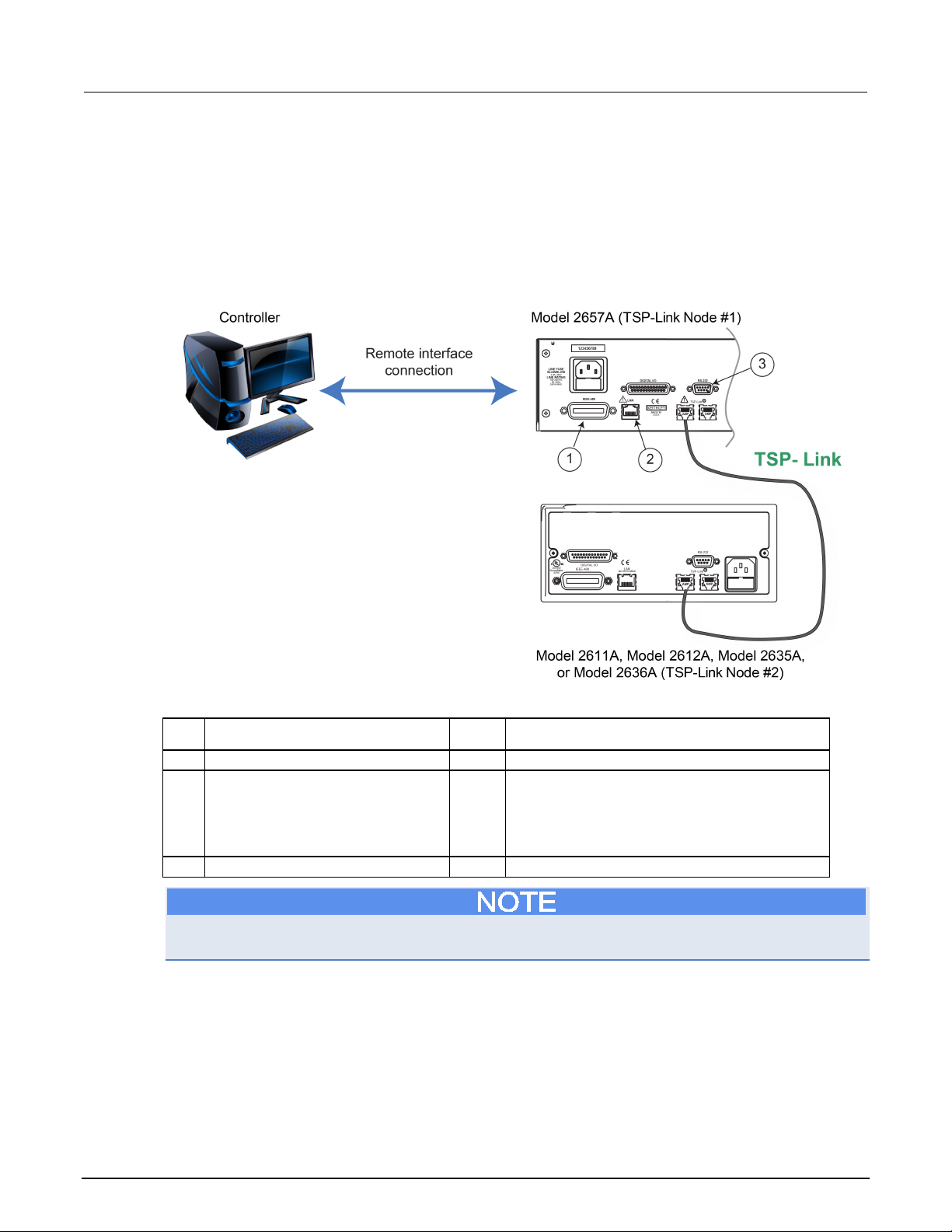
Section
User's Manual
1
IEEE-488 connection
1
GPIB. Model 2657A is IEEE Std 488.1 compliant.
Model CA-180-3 LAN Crossover Cable.
3
RS-232 connection
1
Serial communication port.
9: Measuring thyristor DC characteristics Model 2657A High Power System Sourcemeter® Instrument
Set up communication
The communication setup is illustrated in the following diagram. This application can be run using any
of the supported communication interfaces for the instruments.
For additional detail about remote communications, see "Communications interfaces" in the Model
2657A Reference Manual.
Figure 38: Remote interface and TSP-Link communications setup
Item Description Qty Notes
2 LAN connection 1 Model 2657A is LXI version 1.4 Core 2011
compliant. It supports TCP/IP and complies with
IEEE Std 802.3 (ethernet). 10 or 100 Mbps.
This is available from Keithley Instruments; see
For the first example, no TSP-Link connections are required because only the Model 2657A at
TSP-Link node 1 is used.
9-2 2657A-900-01 Rev. A / April 2012
Page 77

Model 2657A
Measuring thyristor DC characteristics
High Power System Sourcemeter® Instrument User's Manual Section 9:
Device connections
Refer to the following figures to connect the thyristor in a safe test fixture.
See Safe configuration and test setup (on page 2-1
) for information on safely connecting the Model
2657A to a device under test (DUT).
If a device under test fails, high voltage may be present at a terminal to which Series 2600A
instruments are connected. This could damage a Series 2600A instrument. To prevent damage to the
Series 2600A instrument, use a Model 2657A-PM-200 Protection Module. Failure to use a protection
module could result in equipment damage.
Figure 39: Schematic for gated thyristor application example
2657A-900-01 Rev. A / April 2012 9-3
Page 78

Section
User's Manual
1
Model 2657A protective earth (safety
1
Additional connections for redundant protective
protective earth (safety ground) cable assembly.
2
Interlock connection
1
Model 2657A digital I/O; pin 24 (INT) and pin 22
connection
4
Interlocked metal safety enclosure
1
A safety enclosure with an interlock that has a
normally-open (NO) switch.
5
Test fixture protective earth (safety
ground)
1
Redundant grounds may be required for specific
test setups.
6
Model HV-CA-571-3 High-Voltage
Unterminated Cable Assembly
4
See Using high-voltage triaxial connectors (on
Triaxial Cable
8
Protective earth (safety ground) for
the Model 2657A-PM-200
2
Module
2657A-PM-200 for more information.
10
Model 7078-TRX Triaxial Cable
Assembly
2
11
Series 2600A System SourceMeter®
Instrument
1
Model 2611A, Model 2612A, Model 2635A, or
Model 2636A.
12
Model 2657A
1
9: Measuring thyristor DC characteristics Model 2657A High Power System Sourcemeter® Instrument
Item Description Qty Notes
ground)
3 Test fixture interlock switch
Triaxial Panel-Mount Connector to
7 Model HV-CA-554 High-Voltage
9 Model 2657A-PM-200 Protection
earth may be required.
Keithley Instrument's Model CA-568 is a
(5 VDC) connected to the test fixture lid switch.
Keithley Instrument's Model 7709-308 is a 25-pin
interlock male connector that can be used for
custom connections.
Interlock switch is shown in the disengaged (lid
open) position.
1
page 2-7).
4
1 Refer to documentation provided with Model
If you are using a Model 8010 High Power Test Fixture, see the Interconnect Reference Guide
drawing "Three-terminal DUT with a Model 2657A". Also see the Model 8010 User's Manual for
Model 2657A, Model 2611A, and Model 2612A connections.
9-4 2657A-900-01 Rev. A / April 2012
Page 79

Model 2657A
Measuring thyristor DC characteristics
High Power System Sourcemeter® Instrument User's Manual Section 9:
Figure 40: Connections for gated thyristor application example
2657A-900-01 Rev. A / April 2012 9-5
Page 80

Section
User's Manual
9: Measuring thyristor DC characteristics Model 2657A High Power System Sourcemeter® Instrument
Vdrm and Idrm thyristor measurements
The example code is designed to be run from Test Script Builder or TSB Embedded. It can also be
run from other programming environments, such as Microsoft® Visual Studio® or National Instruments
LabVIEWTM. However, you may need to make changes to the example code to use other
programming environments.
This example performs the V
. The Model 2657A is connected from anode to cathode and performs a voltage sweep while
I
rrm
drm
and I
measurements, and may also be used to determine V
drm
rrm
and
capturing current measurements at each point of the sweep.
This example uses a TSP script to perform the measurement. The script includes two separate
functions for configuring the System SourceMeter Instrument and returning the raw current and
voltage readings from the reading buffer.
The script is written using Test Script Processor (TSP) functions rather than as a single block of inline
code. TSP functions are similar to functions in other programming languages, such as Microsoft
Visual C
®
or Visual Basic®. They must be called before the code in them is executed. Because of this,
®
running the script alone will not execute the test. To execute the test, you need to run the script to
load the functions into test script memory. You then call the functions.
Refer to the documentation for Test Script Builder or TSB Embedded (on page 4-4
) for directions on
how to run scripts and enter commands using the instrument console.
Example code
--[[
offVoltLeakI(startV, stopV, numSteps, measDelay, measRange, iLimit, numNPLC)
Description: This function can be used to determine Vdrm and Idrm or
Vrrm and Irrm of a thyristor. In this function, the Model 2657A will
perform a voltage sweep on the anode and measure the corresponding
leakage current at each step. As no voltage or current bias is required
on the gate terminal of the thyristor, this function can be used with
gated and non-gated devices.
To determine Vdrm and Idrm, connect the Model 2657A from anode to
cathode of the device, and program positive start and stop voltages
for the sweep.
To determine Vrrm and Irrm, connect the Model 2657A from the anode to
the cathode of the device, and program negative start and stop voltages
for the sweep.
9-6 2657A-900-01 Rev. A / April 2012
Page 81

Model 2657A
Measuring thyristor DC characteristics
High Power System Sourcemeter® Instrument User's Manual Section 9:
Parameters:
startV: Starting drain voltage (Vds).
stopV: Final drain voltage (Vds).
numSteps: Number of points in the drain voltage sweep.
measDelay: Measurement delay.
measRange: Current measurement range for the drain current measurements.
iLimit: Current limit (compliance) for the drain current.
numNPLC: Integration time in number of power line cycles.
Example usage:
for Vdrm and Idrm:
offVoltLeakI(0, 800, 501, 0.010, 100e-6, 1e-3, 1)
for Vrrm and Irrm:
offVoltLeakI(0, -800, 501, 0.010, 100e-6, 1e-3, 1)
--]]
function offVoltLeakI(startV, stopV, numSteps, measDelay, measRange, iLimit, numNPLC)
--Initialize SMU.
reset()
errorqueue.clear()
status.reset()
--Configure reading buffers.
smua.nvbuffer1.clear()
smua.nvbuffer1.appendmode = 1
smua.nvbuffer1.collecttimestamps = 1
smua.nvbuffer2.clear()
smua.nvbuffer2.appendmode = 1
smua.nvbuffer2.collecttimestamps = 1
--Configure source parameters for the drain SMU.
smua.source.func = smua.OUTPUT_DCVOLTS
smua.source.levelv = 0
smua.source.limiti = iLimit
smua.source.rangev = stopV
--Configure measurement parameters for the drain SMU.
smua.measure.rangei = measRange
smua.measure.nplc = numNPLC
smua.measure.delay = measDelay
smua.measure.autozero = smua.AUTOZERO_ONCE
step = (stopV - startV)/(numSteps - 1)
voltage = startV
--Run the test.
smua.source.output = 1
for i = 1, numSteps do
smua.measure.iv(smua.nvbuffer1, smua.nvbuffer2)
smua.source.levelv = voltage + step
voltage = voltage + step
end
2657A-900-01 Rev. A / April 2012 9-7
Page 82

Section
User's Manual
startV
volts
Start value for the voltage sweep performed at the anode
stopV
volts
Stop value for the voltage sweep performed at the anode
numSteps
not applicable
Number of steps in the voltage sweep
measDelay
seconds
Measurement delay prior to making a measurement (allows for
source and system settling)
measRange
amps
Current range on which to perform the leakage current
measurements
iLimit
amps
Current limit (compliance) for the Model 2657A
numNPLC
not applicable
Integration time, specified as the number of power line cycles
9: Measuring thyristor DC characteristics Model 2657A High Power System Sourcemeter® Instrument
--Run the test.
smua.source.levelv = 0
smua.source.output = 0
printData()
end
function printData()
if smua.nvbuffer1.n == 0 then
print("No reading in buffer")
else
print("Timestamps\tVoltage\tCurrent")
for i = 1, smua.nvbuffer1.n do
print(string.format("%g\t%g\t%g", smua.nvbuffer1.timestamps[i],
smua.nvbuffer2.readings[i], smua.nvbuffer1.readings[i]))
end
end
end
Example usage
The function in this script allows updates to the test parameters without rewriting or re-running the
script. To run the test, call the offVoltLeakI() function, passing in the appropriate values for test
parameters.
offVoltLeakI() parameters
Parameter Units Description
An example of how to call this function is shown here:
--for Vdrm and Idrm:
offVoltLeakI(0, 800, 501, 0.01, 100e-6, 1e-3, 1)
This function call programs the Model 2657A to sweep from 0 V to +800 V in 501 steps. After each
source step, a 10 ms delay occurs and then the Model 2657A makes a 1 NPLC current measurement
on the 100 µA range. The current limit is set to 1 mA. All current and voltage measurements are
automatically printed to the communication interface at the conclusion of the test.
9-8 2657A-900-01 Rev. A / April 2012
Page 83

Model 2657A
Measuring thyristor DC characteristics
High Power System Sourcemeter® Instrument User's Manual Section 9:
The data that results is shown in the following graphic.
Figure 41: Thyristor measurement sample output
Another example of how to call this function is shown here:
--for Vrrm and Irrm:
offVoltLeakI(0, -800, 501, 0.010, 100e-6, 1e-3, 1)
This function call programs the Model 2657A to sweep from 0 V to −800 V in 501 steps. After each
source step, a 10 ms delay occurs and then the Model 2657A makes a 1 NPLC current measurement
on the 100 µA range. The current limit is set to 1 mA. All current and voltage measurements are
automatically printed to the communication interface at the conclusion of the test.
An example of the output of this test is shown in the graphic below.
Figure 42: Sample output Vrrm
2657A-900-01 Rev. A / April 2012 9-9
Page 84

Section
User's Manual
9: Measuring thyristor DC characteristics Model 2657A High Power System Sourcemeter® Instrument
Determine the holding current of a thyristor
This example determines the holding current of a thyristor. The holding current is the minimum DC
current at which the thyristor turns off after the gate signal is removed.
Two SourceMeter instruments are required for this example. One SourceMeter instrument triggers the
thyristor to turn on by supplying a current to the thyristor's gate terminal. Once triggered, the gate
signal is removed. The Model 2657A applies a voltage bias to the thyristor's anode with an initial
current limit greater than or equal to the specified latching current of the thyristor. This ensures that it
stays in the on-state after the gate signal is removed. The current limit is gradually decreased until the
device turns off. This final current is the holding current.
Example code
--[[
holdingCurr(gateBiasCurr, gateVoltLimit, gateOnTime, anodeBiasVolt,
anodeLatchingCurr, anodeCurrStep, numNPLC)
Description: This function can be used to determine Ih of a thyristor.
Two SMUs are required for this function. One SMU (node[2].smua) is
connected to the gate terminal and is used to trigger the device.
The Model 2657A (smua) is connected to the anode and is applying
a voltage bias.
After the device is turned on, the gate signal is removed and the
current limit of the Model 2657A is varied until the device turns off.
The current at which the device turns off is the holding current.
Parameters:
gateBiasCurr = Current to apply to the gate to trigger the device on.
Should be greater than or equal to the gate trigger current.
gateVoltLimit = Voltage limit for the gate SMU. Should be greater
than or equal to the gate trigger voltage.
gateOnTime = Number of seconds to apply the gate trigger
(single pulse event).
anodeBiasVolt = Model 2657A applies this voltage to the anode terminal.
anodeLatchingCurr = Specified latching current of the device.
This will be the initial current limit of the Model 2657A.
anodeCurrStep = How much to vary the anode current in order to
arrive at the holding current.
numNPLC = Integration time in number of power line cycles.
Example usage:
holdingCurr(0.05, 10e-3, 2, 12, 0.06, 0.005, 1)
--]]
function holdingCurr(gateBiasCurr, gateOnTime, gateVoltLimit, anodeBiasVolt,
anodeLatchingCurr, anodeCurrStep, numNPLC)
--Initialize instruments and clear errors and status registers.
tsplink.reset()
reset()
errorqueue.clear()
status.reset()
9-10 2657A-900-01 Rev. A / April 2012
Page 85

Model 2657A
suring thyristor DC characteristics
High Power System Sourcemeter® Instrument User's Manual Section 9: Mea
--Configure gate SMU.
node[2].smua.source.func = node[2].smua.OUTPUT_DCAMPS
node[2].smua.source.rangei = gateBiasCurr
node[2].smua.source.leveli = gateBiasCurr
node[2].smua.source.limitv = gateVoltLimit
node[2].smua.source.delay = 0
--Configure anode SMU source parameters.
smua.source.func = smua.OUTPUT_DCVOLTS
smua.sense = smua.SENSE_LOCAL
smua.source.rangev = anodeBiasVolt
smua.source.levelv = anodeBiasVolt
smua.source.limiti = anodeLatchingCurr
--[[
This is the initial current limit to ensure that the device stays
on after the gate.
--]]
--Configure anode SMU measure parameters.
smua.measure.rangei = anodeLatchingCurr
smua.measure.nplc = numNPLC
smua.measure.autozero = smua.AUTOZERO_ONCE
numSteps = ((anodeLatchingCurr - 0) / (anodeCurrStep)) + 1
if anodeCurrStep >= anodeLatchingCurr then
print("Wrong value: The current step cannot be greater than or equal to the
expected latching current.")
else
smua.source.output = 1
node[2].smua.source.output = 1
delay(gateOnTime)
node[2].smua.source.output = 0
for i = 1, numSteps do
smua.measure.i()
cmplCheck = smua.source.compliance
if cmplCheck == false then
break
else
smua.source.limiti = anodeLatchingCurr - (i*anodeCurrStep)
end
end
--Complete the test and output the result.
smua.source.output = 0
finalIh = smua.source.limiti
print("Holding Current (Amps): ", finalIh)
end
end
2657A-900-01 Rev. A / April 2012 9-11
Page 86

Section
User's Manual
gateBiasCurr
amps
Gate current to apply with the Series 2600A
SourceMeter instrument.
gateVoltLimit
connected to the thyristor's gate terminal.
gateOnTime
seconds
Amount of time to apply the gate signal.
anodeBiasVolt
volts
Anode voltage provided by the Model 2657A.
anodeLatchingCurr
amps
Specified latching current of the thyristor. This is also
connected to the anode terminal. The latching current is
this test.
anodeCurrStep
amps
The step size of the change in anode current.
numNPLC
not applicable
Integration time, specified as number of power line
cycles.
9: Measuring thyristor DC characteristics Model 2657A High Power System Sourcemeter® Instrument
Example usage
The functions in this script allow updates to the test parameters without rewriting or re-running the
script. To run the test, call the holdingCurr() function, passing in the appropriate values for test
parameters.
holdingCurr() parameters
Parameter Units Description
volts Voltage limit (compliance) for the Series 2600A
the initial current limit (compliance) of the Model 2657A
typically more than or equal to the holding current.
Ensure that this value is larger than holding current for
An example of how to call this function is shown here:
holdingCurr(0.05, 10e-3, 2, 12, 0.06, 0.005, 1)
This function call uses the Series 2600A SourceMeter Instrument to apply 50 mA for 2 s to trigger the
thyristor to turn on. Meanwhile, the Model 2657A applies 12 V to the anode with an initial current limit
of 60 mA. Since the device is in the on-state, the Model 2657A should be in current limit. The current
limit is decreased in 5 mA increments. The program monitors the current limit bit of the status register
in order to determine when the Model 2657A returns to normal voltage sourcing conditions, which
indicates that the device has turned off. This final programmed current limit is the holding current.
The result of the function call for this example is:
Holding Current (Amps): 2.40000e-02
Determine the latching current of a thyristor
This example determines the latching current of a thyristor. The latching current is the minimum DC
anode current at which the device remains in the on-state after the gate signal is removed.
Two SourceMeter instruments are required for this example. The Series 2600A SourceMeter
Instrument provides a repetitive square-wave like signal to the gate to trigger and re-trigger the
device. The Model 2657A supplies current to the thyristor's anode. Each time the gate is removed,
the program checks the Model 2657A voltage limit to determine if the device is on. If the device has
not stayed on, the anode current is increased and the device is re-triggered. This process continues
until the thyristor remains on even after the gate signal is removed. The first anode current at which
this occurs is the latching current.
9-12 2657A-900-01 Rev. A / April 2012
Page 87

Model 2657A
Measuring thyristor DC characteristics
High Power System Sourcemeter® Instrument User's Manual Section 9:
Example code
--[[
latchingCurr(gateBiasCurr, gateVoltLimit, gateOnTime, anodeStartCurr,
anodeMaxCurr, anodeStepCurr, anodeVoltLimit, numNPLC)
Description: This function can be used to determine Ilatch of a
thyristor. Two SMUs are required for this function. One SMU
(node[2].smua) is connected to the gate terminal and is used to
trigger the device. The Model 2657A (smua) is connected to the anode
and is used to source the current.
The gate is triggered while a current bias is applied to the anode.
The gate current is removed and measurements are made to verify that the
device is on. If the device is off, the current at the anode is
increased and the gate is re-triggered. This continues until the
device remains on even after the gate signal is removed.
The current at which the device remains on is the latching current.
In order to complete this task, custom list sweeps are configured on
the gate and anode SMUs.
Parameters:
gateBiasCurr = Current to apply to the gate to trigger the device on.
Should be greater than or equal to the gate trigger current.
gateVoltLimit = Voltage limit for the gate SMU. Should be greater
than or equal to the gate trigger voltage.
gateOnTime = Number of seconds to apply the gate trigger
(single pulse event).
anodeStartCurr = Start value for the anode current sweep.
Typically slightly less than or equal to the holding current value.
anodeMaxCurr = Stop value for the anode current sweep. May not reach
this value, but this is the maximum value to source.
anodeStepCurr = Step value for the anode current sweep.
anodeVoltLimit = Voltage limit for the anode SMU. Should be equal
to Vdrm.
numNPLC = Integration time in number of power line cycles.
Example usage:
latchingCurr(0.060, 10, 1e-3, 0.020, 0.120, 0.005, 600, 0.01)
--]]
function latchingCurr(gateBiasCurr, gateVoltLimit, gateOnTime, anodeStartCurr,
anodeMaxCurr, anodeStepCurr, anodeVoltLimit, numNPLC)
--Initialize instruments and clear errors and status registers.
tsplink.reset()
reset()
errorqueue.clear()
status.reset()
2657A-900-01 Rev. A / April 2012 9-13
Page 88

Section
User's Manual
9: Measuring thyristor DC characteristics Model 2657A High Power System Sourcemeter® Instrument
--Configure gate SMU.
node[2].smua.source.func = node[2].smua.OUTPUT_DCAMPS
node[2].smua.source.rangei = gateBiasCurr
node[2].smua.source.leveli = 0
node[2].smua.source.limitv = gateVoltLimit
node[2].smua.source.delay = gateOnTime
--Configure anode SMU source parameters.
smua.source.func = smua.OUTPUT_DCAMPS
smua.sense = smua.SENSE_LOCAL
smua.source.rangei = anodeMaxCurr
smua.source.leveli = 0
smua.source.limitv = anodeVoltLimit
--Configure anode SMU measurement parameters.
smua.measure.delay = 0.005
--Must have delay if you want reasonable anode measurements.
smua.measure.rangev = anodeVoltLimit
smua.measure.nplc = numNPLC
smua.measure.autozero = smua.AUTOZERO_ONCE
smua.nvbuffer1.clear()
smua.nvbuffer2.clear()
smua.nvbuffer1.appendmode = 1
smua.nvbuffer2.appendmode = 1
smua.nvbuffer1.collecttimestamps = 1
smua.nvbuffer2.collecttimestamps = 1
--Create custom sweeps for anode and gate SMUs.
numSwpPts = 2*((anodeMaxCurr - anodeStartCurr)/(anodeStepCurr)) + 1
gateSwp = {}
anodeSwp = {}
for i = 1, numSwpPts do
if math.mod(i,2) == 0 then
gateSwp[i] = 0
else
gateSwp[i] = gateBiasCurr
end
end
for j = 1, numSwpPts, 2 do
anodeSwp [j] = anodeStartCurr + ((j-1)/2)*anodeStepCurr
anodeSwp[j+1] = anodeStartCurr + ((j-1)/2)*anodeStepCurr
end
9-14 2657A-900-01 Rev. A / April 2012
Page 89

Model 2657A
Measuring thyristor DC characteristics
gateBiasCurr
2600A SourceMeter instrument.
gateVoltLimit
volts
Voltage limit (compliance) for the Series
the thyristor.
gateOnTime
seconds
Amount of time to apply the gate signal.
anodeStartCurr
amps
Initial anode current provided by the Model
specified latching current.
anodeMaxCurr
amps
Maximum anode current to apply with the
Model 2657A.
anodeStepCurr
amps
Step size of the current sweep occurring at
the anode of the thyristor.
anodeVoltLimit
volts
Voltage limit (compliance) of the Model
2657A.
numNPLC
not applicable
Integration time, specified as the number of
power line cycles.
High Power System Sourcemeter® Instrument User's Manual Section 9:
smua.source.output = 1
node[2].smua.source.output = 1
for k = 1, numSwpPts, 2 do
smua.source.leveli = anodeSwp[k]
node[2].smua.source.leveli = gateSwp[k]
node[2].smua.source.leveli = gateSwp[k+1]
smua.measure.iv(smua.nvbuffer1,smua.nvbuffer2)
checkCmpl = smua.source.compliance
--[[
If in compliance, then device is off. If out of compliance, then
device is on and we have reached latching current.
--]]
if checkCmpl == false then
finalIL = anodeSwp[k]
break
end
end
node[2].smua.source.output = 0
smua.source.output = 0
print("Latching current(amps): ", finalIL)
print("Raw data follows:")
printData()
end
Example usage
The function in this script allows updates to the test parameters without rewriting or re-running the
script. To run the test, call the latchingCurr() function, passing in the appropriate values for test
parameters.
latchingCurr() parameters
Parameter Units Description
amps Gate current to apply with the Series
2600A connected to the gate terminal of
2657A. Should be much less than the
2657A-900-01 Rev. A / April 2012 9-15
Page 90

Section
User's Manual
9: Measuring thyristor DC characteristics Model 2657A High Power System Sourcemeter® Instrument
An example of how to call this function is shown here:
latchingCurr(0.060, 10, 1e-3, 0.020, 0.120, 0.005, 600, 0.01)
This call uses the Series 2600A SourceMeter instrument to apply 60 mA for 1 ms to trigger the
thyristor to turn on. Meanwhile, the Model 2657A applies 20 mA to the anode terminal. The gate
signal is removed by programming the Model 2600A to force zero amps.
The program monitors the voltage limit on the Model 2657A. If the voltage limit is indicated, the
device is off. The Model 2657A then increases the supplied anode current and the device is
re-triggered. This process is repeated until the thyristor remains on. This final programmed current
limit is the latching current.
The result of the function call for this example is:
Latching Current (Amps): 2.90000e-02
9-16 2657A-900-01 Rev. A / April 2012
Page 91

Why is the reading value 9.92e37? ........................................ 10-3
In this section:
About this section ................................................................... 10-1
How do I change the line frequency or voltage? .................... 10-1
Where can I find updated drivers? ......................................... 10-2
Can I convert to coaxial cables? ............................................ 10-2
How do I connect LO terminals of multiple SMUs together? .. 10-2
What should I do if I get an 802 interlock error? ..................... 10-3
Why is the reading value 9.91e37? ........................................ 10-3
About this section
Section 10
Troubleshooting FAQs
The purpose of this section is to help you troubleshoot the most common problems encountered with
the Model 2657A. For additional troubleshooting information, please see the "Troubleshooting"
section in the Model 2657A Reference Manual.
How do I change the line frequency or voltage?
I need to use a Model 2657A at a different power line frequency or voltage. What do I need to
do?
The Model 2657A requires a line voltage of 100 V AC to 240 V AC (±10%), and a line frequency of
50 Hz or 60 Hz. Keithley Instruments sets the line frequency of the Model 2657A for the final shipping
destination of the instrument.
You can manually configure the instrument to match the actual line frequency.
To configure the line frequency from the front panel:
1. Press the MENU key.
2. Turn the navigation wheel to select LINE-FREQ.
3. Press the ENTER key.
4. Turn the navigation wheel to select the appropriate frequency.
5. Press the ENTER key.
6. Press the EXIT (LOCAL) key to return to the default display screen.
Page 92
Section
User's Manual
10: Troubleshooting FAQs Model 2657A High Power System Sourcemeter® Instrument
Where can I find updated drivers?
For the latest drivers and additional support information, see the Keithley Instruments support
website.
To see what drivers are available for your instrument:
1. Go to the Keithley Instruments support website (http://www.keithley.com/support
2. Enter the model number of your instrument.
3. Select Software Driver from the list.
For LabVIEW, you can also go to National Instrument's website and search their instrument driver
database.
Can I convert to coaxial cables?
Use the optional cable assembly (Keithley Instruments part number SHV-CA-553), which converts a
high-voltage triaxial connector to a safe high-voltage (SHV) connector. See
(SHV) (on page 2-4) for detail.
).
Using coaxial connections
How do I connect LO terminals of multiple SMUs together?
To connect the SENSE LO and LO terminals of the Model 2657A to other source-measure units
(SMUs), use the Model 2657A-LIM-3 LO Interconnect Module. For more details, refer to the Model
2657A-LIM-3 LO Interconnect Module documentation (PA-1063).
If you are connecting to a lower-voltage SMU, you must first connect the lower-voltage SMU to a
Keithley Instruments Model 2657A-PM-200 Protection Module using triaxial connections only.
Compatible lower-voltage SMUs include the Models 2611A, 2612A, 2635A, 2636A, 4200-SCS,
4200-SMU, and 4210-SMU. For more information about the Model 2657A-PM-200 protection module,
refer to the Model 2657A-PM-200 Protection Module documentation (PA-1055).
The Model 2657A High Power System SourceMeter® Instrument and its associated cabling
are designed to be safe when operated correctly in a 3000 V system. They are only
warranted to the maximum voltage and current ratings of the instrument. Connecting two
Model 2657A instruments in parallel or in series may result in voltages or power levels that
exceed the safety mechanisms. This increases the risk of instrument damage and the
possibility of personal injury or death due to electric shock. The user assumes all of the
associated risks of combining the outputs of two or more Model 2657A instruments.
10-2 2657A-900-01 Rev. A / April 2012
Page 93

Model 2657A
Troubleshooting FAQs
High Power System Sourcemeter® Instrument User's Manual Section 10:
What should I do if I get an 802 interlock error?
You will receive error code 802, "OUTPUT blocked by interlock," if you:
• Disengage the interlock when the Model 2657A output is already on
• Attempt to turn on the Model 2657A output when the interlock is disengaged
To recover from this error, properly engage the interlock using a safe test fixture, and then turn on the
Model 2657A output.
Why is the reading value 9.91e37?
This value indicates that there is a measurement overflow error. This error occurs when:
• A measurement performed on a fixed range has a measured value greater than the specified
range
• The measured value is larger than the maximum current or voltage range of the instrument
(exceeds the instrument rating)
If the instrument displays the overflow message on a particular range, select a higher range until an
on-range reading is displayed. To ensure the best accuracy and resolution, use the lowest range
possible that does not cause an overflow.
Why is the reading value 9.92e37?
This value indicates an overvoltage condition. This can occur if:
• The overvoltage protection (OVP) limit value is exceeded
• There are incorrect connections to the device under test (DUT)
• Remote sense is enabled and the sense HI and sense LO are improperly or incorrectly connected
to the DUT
The OVP limit can be set from the Model 2657A front panel or through a remote interface.
To set the OVP limit from the instrument front panel:
1. Press the CONFIG key, and then select SRC > V-SOURCE > PROTECTION.
2. Enter the desired OVP value.
3. Press Enter.
To set the OVP limit through a remote interface, use the smuX.source.protectv attribute (see the
"Command reference" section in the Model 2657A Reference Manual for details about this
command).
For more information about overvoltage protection, see "Overvoltage protection (OVP)" in the Model
2657A Reference Manual.
2657A-900-01 Rev. A / April 2012 10-3
Page 94

Page 95

Additional Model 2657A information ....................................... 11-1
In this section:
Additional Model 2657A information
For additional information about the Model 2657A, refer to:
• The Product Information CD-ROM (which ships with the product). Contains software tools,
drivers, and product documentation
• The Keithley Instruments website (http://www.keithley.com): Contains the most up-to-date
product information; from the website, you can access:
• The Knowledge Center, where you can order the following handbooks:
• The Low Level Measurements Handbook: Precision DC Current, Voltage, and Resistance
Measurements
• Switching Handbook: A Guide to Signal Switching in Automated Test Systems
• Application notes
• Updated drivers
• Information on related products, including:
• The Model 4200-SCS Semiconductor Characterization System
• The Series 2600A System SourceMeter
• The Model 2651A High Power System SourceMeter instrument
• The Model 8010 High Power Device Test Fixture
• Your local Field Applications Engineer can help you with product selection, configuration, and
usage. Check the website for contact information.
®
Section 11
Next steps
instruments
Page 96

Page 97

Index
A
abort script • 4-7
applications
basic front panel measurements • 5-1
measure diode characteristics • 6-1
measure leakage current and insulation
resistance of capacitors • 7-1
measure thyristor DC characteristics • 9-1
MOSFET characterization • 8-1
thyristor DC characteristics • 9-1
C
coaxial connections • 2-4
compliance limits
set through front panel • 5-4
connection
device • 5-2
diode application • 6-3
front-panel measurement • 5-2
MOSFET application • 8-3
thyristor appplication • 9-3
web interface • 4-1
D
delete script • 4-7
Discovery Tool, LXI • 4-1
display
observing readings • 4-7, 5-5
download
reading buffer • 4-7
E
error messages
interlock • 10-3
example applications
basic front panel measurements • 5-1
measure diode characteristics • 6-1
measure leakage current and insulation
resistance of capacitors • 7-1
measure thyristor DC characteristics • 9-1
MOSFET characterization • 8-1
exercises
create and run script with TSB Embedded • 4-4
retrieve readings from buffer • 4-7
export script • 4-7
F
FAQs • 10-1
front panel • 3-2
compliance limit • 5-4
indicators • 3-2
interface • 3-1
measurements • 5-1, 5-4
output, on/off • 5-4
readings • 5-5
source-measure procedure • 5-4
using • 3-1
functions
selecting • 5-4
H
HV triaxial connections • 2-7
I
import script • 4-7
indicators • 3-2
interlock • 2-3
error • 10-3
IP address • 4-3
J
Java plug-in • 4-1
K
keypad • 3-4
keys • 3-2, 3-3
L
LXI Discovery Tool • 4-1
download • 4-1
M
measurement
front panel • 5-1, 5-4
function, selecting • 5-4
ranges • 5-4
thyristor DC characteristics • 9-1
N
navigation wheel • 3-2, 3-4
Page 98

Index
Model 2657A High Power System Sourcemeter® Instrument
User's Manual
number keys • 3-3
O
operation keys • 3-3
output enable • 5-4
OUTPUT ON/OFF control • 3-2, 5-4, 5-5
R
range
selecting autorange • 5-4
reading buffer • 4-7
displaying readings • 4-7
downloading • 4-7
readings
display • 5-5
observing • 4-7, 5-5
S
scripts
abort • 4-7
clearing • 4-7
create in TSB Embedded • 4-4
deleting • 4-7
exporting • 4-7
importing • 4-7
management • 4-7
stopping • 4-7
viewing • 4-7
SHV coaxial • 2-4
source
level • 5-4
IP address configuration • 4-3
reading buffers • 4-7
TSB Embedded • 4-4
TSP Express • 4-9
using • 4-1
T
triaxial connections • 2-7
troubleshooting • 10-1
FAQs • 10-1
IP address • 4-1, 4-3
line frequency • 10-1
voltage • 10-1
web page • 4-1, 4-2
TSB Embedded • 4-4
script, create with • 4-4
TSP Express • 4-9
V
voltage
source, set level • 5-4
W
Warranty • 1-1
web interface • 4-1
accessing • 4-1
browser requirements • 4-1
Home page • 4-2
Index-2 2657A-900-01 Rev. A / April 2012
 Loading...