

Page 1

Model 262
Instruction Manual
Low Thermal Voltage Divider
Page 2
WARRANTY
Keithley Inslrumenls. Inc. warrants this producl to be free from defects in material
and workmanship for a period of I year from date of shipmem.
Keithley Inslrumen&. Inc. warranls the following items for 90 days from the date
of shipment: probes, cables, rechargeable batteries, diskettes, and documentation.
During the warranty period, we will, at our option. either repair or replace any
product Ihal proves to be defecrive.
To exercise [his warranty, write or call your local Keithley representative. or con-
lacr Keithley headquarrers in Cleveland, Ohio. You will be given prompt assistance
and return inslructions. Send lhe product, lransportation prepaid, to rhe indicated
service facilily. Repairs will be made and the product returned, transportation prepaid. Repaired or replaced producls are warranted for the balance of the original
warranty period, or al leas1 90 days.
LIMITATION OF WARRANTY
This warranty does not apply to defects resulting from product modilication withoul
Keithley’s express wrilten consem, or misuse of any producl or pan. This warranty
also does not apply to fuses. sofware. non-rechargeable batteries, damage from bal-
tery leakage. or problems arising from normal wear or failure 10 follow instructions.
THIS WARRANTY IS IN LIEU OFALL OTHER WARRANTIES, EXPRESSED
OR IMPLIED, INCLUDING ANY IMPLIED WARRANTY OF MERCHANTABILITY OR FITNESS FOR A PARTICULAR USE. THE REMEDIES PRO-
VIDED HEREIN ARE BUYER’S SOLE AND EXCLUSIVE REMEDIES.
NEITHER KEITHLEY INSTRUMENTS, INC. NOR ANY OF ITS EMPLOY-
EES SHALL BE L1ABI.E FOR ANY DIRECT, INDIRECT, SPECIAL, INCI-
DENTAL OR CONSEQIJENTIAL DAMAGES ARISING OUT OF THE USE OF
ITS INSTRUMENTS AND SOFTWARE EVEN IF KEITHLEY INSTRU-
MENTS, INC.. HAS BEEN ADVISED IN ADVANCE OF THE POSSlBlLITY
OF SUCH DAMAGES. SUCH EXCLUDED DAMAGES SHALL INCLUDE,
BUT ARE NOT LIMITED TO: COSTS OF REMOVAL AND INSTALLATION,
LOSSES SUSTAINED AS THE RESULT OF INJURY TO ANY PERSON, OR
DAMAGETO PROPERTY.
Page 3

Model 262 Low Thermal Voltage Divider
Instruction Manual
@1982, Keithley Instruments, Inc.
All rights rcservcd.
Cleveland, Ohio, U.S.A.
Fourth Printing, May 2000
Document Number: 262-901-01 Rev. D
Page 4

Page 5

Safety Precautions
The following safety precautions should be observed before using this product and any associated instrumentation. Although some instruments and accessories would normally be used
with non-hazardous voltages, there arc situations where hazardous conditions may bc present.
This product is intended for use by qualified personnel who recognize shock hazards and are
familiar with the safety precautions required to avoid possible injury. Read the upcrating information carefully before using the product.
The types of product users are:
Responsible body is the individual or group responsible for the use and maintenance of
equipment, for cnsuring that the equipment is operated within its specifications and operating limits, and for ensuring that operators are adequately trained.
Operators use the product for its intended function. They must be vained in electrical safety
procedures and proper use of the inatmment. They must be protected from elec(nc shock and
contact with hazardous live circuits.
Maintenance personnel perform routine procedures on the product to keep it operating, for
example, setting the line voltage or replacing consumable materials. Maintenance procedures
arc described in the manual. The procedures explicitly state if the operator may perform them.
Otherwise, they should be performed only by service personnel.
Service personnel are trained to work on live circuits, and perform safe installations and rc-
pairs of products. Only properly trained service personnel may perform installation and ser-
vice procedures.
Exercise extreme caution when a shock hazard is present. Lethal voltage may be present on
cable connector jacks or test lixtures. The American National Standards Institute (ANSI)
sratcs that a shock hazard exists when voltage levels greater than 30V RMS, 42.4V peak, or
60VDC are present. A good safety practice is to expect that hazardous voltage is present
in any unknown circuit befure measuring.
Users of this pmduct must be protected from elecaic shock at all times. The responsible body
mustenwe tidt users are prevented access and/or insulated fromevery connection point. In some
cases, connections must be exlxxd to potential human confacf. Product users in these circun-
stances must be trained to pro&t themselves from the risk of electric shock. If the circuit is capable of operating at or above loo0 volts, no conductive part of the circuit may be exposed.
As described in the International Electrotechnical Commission (IEC) Standard IEC 664, dig-
ital multimeter measuring circuits (e.g.. Keitbley Models l75A, 199,2OOO, 2001, 2002, and
2010) are Installation Category II. All other instruments’ signal terminals are installation Cat-
egory I and must not be connected to mains.
Do not connect switching cards directly to unlimited power circuits. They arc intended to be
used with impedance limited sources. NEVER connect switching cards directly to AC mains.
When connecting sources to switching cards. install protective devices to limit fault currcnt
and voltage to the card.
Before operating an insuument, make sure the line cord is connected to a properly grounded
power receptacle. Inspect the connecdng cables, test leads, and jumpers for possible wear,
cracks. or breaks before each use.
For maximum safety, do not touch the product, test cables. or any other instmments while pow-
er is applied to the circuit under test. ALWAYS remove power from the entire test system and
discharge any capacitors beforo: connecting or disconnecting cables or jumpers, installing or
Page 6
removing switching cards, or making internal changes, such as installing or removing jumpers.
Do not touch any object that could provide a current path to the common side of the circuit
under test or power line (earth) ground. Always make measurements with dry hands while
standing on a dry, insulated surface capable of withstanding the voltage being measured.
The instrument and accessories must he used in accordance with its specifications and operating instructions or the safety of the equipment may he impaired.
Do not excwd the maximum signal levels of the instruments and accessories, as de6ned in
the specifications and operating information, and as shown on the instrument or test fixture
panels, or switching card.
When fuses are used in a product, replace with same type and rating for continued protection
against fire hazard.
Chassis connections must only he used ns shield connections for measuring circuits, NGT as
safety earth ground connections.
If you are using a test lixture. keep the lid closed while power is applied to the device under
test. Safe operation requires the use of a lid interlock.
Ifa @ screw is present, connect it to safety earth ground using the wire recommended in
the user documentation.
The A symbol on 8.n instrument indicates that the user should refer to the operating in-
structions located in the manual.
Then. symbol on an insbument shows that it can source or measure 10X volts or more, in-
cluding the combined effect of normal and common mode voltages. Use standard safety precnutions to avoid personal contact with these voltages.
The WARNING heading in a manual explains dangers that might result in personal injury or
death. Always read the associated information very carefully before performing the indicated
procedure.
The CAUTION heading in a manual explains hazards that could damage the instrument.
Such damage may invalidate the warranty.
Instrumentation and accessories shall not be connected to humans.
Before performing any maintenance, disconnect the line cord and all test cables.
To maintain protection from electric shock and fire, replacement components in mains cir-
cuits, including the pnwer transformer, test leads, and input jacks, must be purchased from
I-&id&y Insh’uments. Standard fuses, with applicable national safety approvals, may be used
if the rnting and type are the same. Other components that are not safety related may he purchased from other suppliers as long as they nre equivalent to the original component. (Note
that selected parts should he purchased only through Keitbley Instruments to maintain nccuracy and functionnlity of the product.) If you are unsure about the applicability of a replacement component, call a Keithley Instruments office for information.
To clean an instrument, use a damp cloth or mild, writer based cleaner. Clean the exterior
of the instrument only. Do not apply cleaner directly to the instruiuent or allow liquids to
enter or spill on the instrument. Products that consist of a circuit board with no case or chas-
sis (e.g., data acquisition board for installation into a computer) should never require cleaning if handled according to instructions. If the board becomes contaminated and operation
is affected, the board should be returned to the factory for proper cleaning/servicing.
Rc”. 10199
Page 7
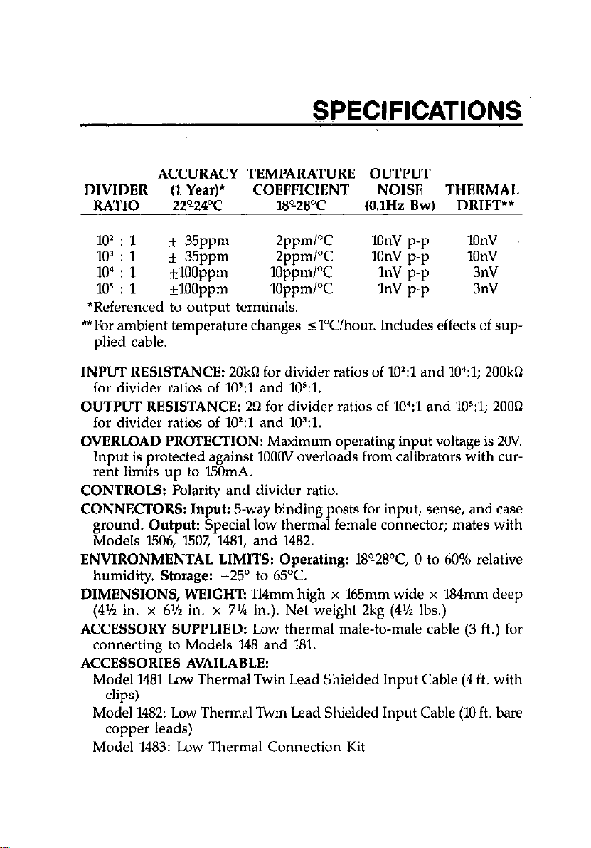
SPECIFICATIONS
ACCURACY TEMI’ARATURE OUTPUT
DIVIDER (1 Year)* COEFFICIENT NOISE THERMAL
RATIO
220-24’C W280C
(O.lHz Bw) DRIFT**
101 : 1
103 : 1
10’ : 1
105 : 1
* 35ppm
* 35ppm
*lOOppm
*lOOppm
2ppmPC 1onv p-p
2ppmPC 1onv p-p 1onv
10ppmPC 1nv p-p 3nV
lOppm/Yz 1nv p-p 3nv
1onv
*Referenced to output terminals.
**br ambient temperature changes ~1”Clhour. Includes effects of sup-
plied cable.
INPUT RESISTANCE:
20khl for divider ratios of lo?1 and 1O’:l; 200kn
for divider ratios of lo’:1 and 105:1.
OUTPUT RESISTANCE:
261 for divider ratios of lo’:1 and 10s:l; 2000
for divider ratios of lo’:1 and lO?l.
OVERLOAD PROTECHON:
Maximum operating input voltage is 20V.
Input is protected against 1OOOV overloads from calibrators with current limits up to 150mA.
CONTROLS:
CONNECTORS: Input: 5.~3~
ground.
Polarity and divider ratio.
binding posts for input, sense, and case
Output:
Special low thermal female connector; mates with
Models 1506, 1507, 1481, and 1482.
ENVIRONMENTAL LIMITS: Operating:
humidity.
DIMENSIONS, WEIGHT:
Storage: -25”
to 65°C.
114mm high x 165mm wide x 184mm deep
18%28’C, 0 to 60% relative
(4’/2 in. x 6% in. x 7’/a in.). Net weight 2kg (4% Ibs.).
ACCESSORY SUPPLIED:
Low thermal male-to-male cable (3 ft.) for
connecting to Models 148 and 181.
ACCESSORIES AVAILABLE:
Model 1481 Low Thermal Twin Lead Shielded Input Cable (4 ft. with
clips)
Model 1482: Low Thermal Twin Lead Shielded Input Cable (10 ft. bare
copper leads)
Model 1483: Low Thermal Connection Kit
Page 8
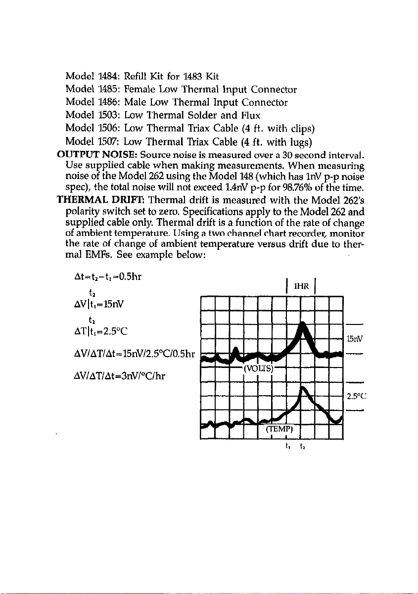
Model 1484: Refill Kit for 1483 Kit
Model 1485: Female Low Thermal Input Connector
Model 1486: Male Low Thermal Input Connector
Model 1503: Low Thermal Solder and Flux
Model 1506: Low Thermal Triax Cable (4 ft. with clips)
Model 1507: Low Thermal Triax Cable (4 ft. with lugs)
OUTPUT NOISE:
Source noise is measured over a 30 second interval.
Use supplied cable when making measurements. When measuring
noise of the Model 262 using the Model 148 (which has 1nV p-p noise
spec), the total noise will not exceed 1.4nV p-p for 98.76% of the time.
THERMAL DRIFT!
Thermal drift is measured with the Model 26’2’s
polarity switch set to zero. Specifications apply to the Model 262 and
supplied cable only. Thermal drift is a function of the rate of change
of ambient temperature. Using a two channel chart recorder, monitor
the rate of change of ambient temperature versus drift due to ther-
mal EMR. See example below:
At=t>-t,=0.5hr
t2
AVlt,=l5nV
ATT;;,=2.5’C
AV/AT/At=3nVPClhr
Page 9
TABLE OF, CONTENTS
GENERAL INFORMATION.. . . . . . . . . . . . . . . . . . . 1
INTRODUCTION ..........................................
OPTIONAL ACCESSORIES.,
WARRANTY INFORMATION
MANUAL ADDENDA ...............................
SAFETY SYMBOLS AND TERMS
UNPACKING AND INSPECTION
REPACKING FOR SHIPMENT
...............................
............................... 2
.........................
...........................
..........................
1
1
..... 2
2
3
..
3
OPERATION
INTRODUCTION ...............
ENVIRONMENTAL CONDITIONS
MODEL 262 CONTROL AND CONNECTORS
MODEL 181 VERIFICATION AND CALIBRATION
(2mV, 20mV and 200mV Ranges)
MODEL 148 NANOVOLT VERIFICATION
DMM CALIBRATION .....................................
.................................
..........................
.................
...........................
....................
.......... 5
..
........ 5
5
5
7
9
10
CALIBRATION . . . . . . . . . . . . . . . . . . . . . . . . . . . . . . 13
INTRODUCTION .........................................
ENVIRONMENTAL CONDITIONS
INITIAL EQUIPMENT CONDITIONS
ADIUSTMENTONE
ADjUSTMENTTWO
ADJUSTMENT THREE ....................................
......................................
......................................
SERVICING INFORMATION
CLEANING INSTRUCTIONS
LOW THERMAL CONNECTIONS
THEORY OF OPERATION
DISASSEMBLY INSTRUCTIONS
REPLACEABLE PARTS
PARTS LlST.. ............................................
ORDERING INFORMATION
FACTORY SERVICE .......................................
.................................
.......................
...............................
.........................
......................
....................
..............................
.........................
...........................
l3
14
15
16
26
26
29
29
30
32
32
35
35
35
35
Page 10
OPERATION
Figure 1. Digital Nanovoltmeter Calibration.
Figure 2. Analog Nanovoltmeter Calibration
Figure 3. DMM Calibration.
................................ 11
.................. 7
.................
CALIBRATION
Figure 4. Calibration Configuration Schematic
Figure 5A. LO Lead Compensation Schematic
Figure 5B. LO Lead Compensation Connection Diagram
Figure 6A. HI Lead Compensation Schematic.,
Figure 6B. HI Lead Compensation Connection Diagram
Figure 7A. Pot Adjustment Set Up Schematic
Figure 7B. Pot Adjustment Connection Diagram
Figure 8. Calibration Adjustments
..........................
............... 14
...............
..............
................
.............
SERVICING INFORMATION
Figure 9. Model 262 Mechanical Parts
Figure 10. Divider Ratio Switch
....................... 36
.............................
REPLACEABLE PARTS
Figure 11. Model 262, Component Location Drawing,
Dwg. No. 262-100
Figure 12. Model 262, Schematic Diagram,
Dwg. No. 262-106,
.......................................
.......................................
10
18
...... 19
20
...... 21
24
25
28
37
39
40
ii
Page 11
OPERATION
Table 1. Model 181 Verification (2mV, 20mV and 200mV) 8
Table 2. Model 181 Calibration (2mV, 20mV and 204lmV) 8
Table 3. Model 148 Verification. 9
Table 4. DMM Calibration 11
CALIBRATION
Table 5. Recommended Equipment 16
Table 6. Calibration Limits. 27
REPLACEABLE PARTS
Table 7. Model 262, Parts List.. 38
iii/iv
Page 12

Page 13

GENERAL INFORMATION
INTRODUCTION
The Model 262 is a precision low thermal divider with divider ratios
of lO’:l, lO’:l, lo’:1 and 105:1. The Model 262 is designed to calibrate
nanovoltmeters and 1pV sensitive DMMs. A low thermal male-to-male
output cable is included with the Model 262.
OPTIONAL ACCESSORIES
Model 1481 Low Thermal Input Cable is useful for making temporary
connections in low voltage circuits. The 1.2m (4’) cable is terminated
with two alligator clips and a male low thermal connector. Recommended for use with the Model 148 Nanovoltmeter.
Model 1482 Low Thermal Input Cable allows a user to make his own
special, low thermal input connections for the Model 148. The 3m (10’)
cable is terminated with a male, low thermal connector and two bare
copper leads.
Model 1483 Law Thermal Connection Kit is useful for making low thermal connections in experimental setups. The kit contains a crimp tool,
pure copper lugs, alligator clips, low thermal cadmium solder and
assorted hardware.
Model 1484 Refill Kit contains replacement parts for the Model 1483
Low Thermal Connection Kit.
Model 1485 Female Low Thermal Input Connector is the connector for
Models 148, 181, and 262.
Model 1486 Male Low Thermal Connector mates with the input connector for Models 148, 181 and 262. It allows the user to make a custom
length input cable.
Model 1503 Low Thermal Solder is useful when making connections
to low voltage circuits.
Page 14
Model I506 Low Thermal Input Cable is a triaxial1.2m (4’) cable specially designed to provide excellent shielding for input connections to the
Model 181. It has a mating connector and two copper alligator clips.
Recommended for use with the Model 262.
Model I5W Low Thermal Input Cable is a triaxial cable, 1.2m (4’),
similar to the Model W06, but has two copper spade lugs instead of
clips. Recommended for use with the Model 262.
WARRANTY INFORMATION
Warranty information is provided on the inside, front cover of this
manual. If there is a need to exercise the warranty, contact the Keithley
representative in your area to determine the proper action to be taken.
Information concerning the applicaton, operation or service of your instrument may be directed to the applications engineer. Check the inside front cover of this manual for addresses.
MANUAL ADDENDA
Improvements or changes to this manual will be explained on an addendum included with this manual.
SAFETY SYMBOLS AND TERMS
Safety symbols used in this manual are as follows:
The symbol A on the instrument denotes that the user should refer
to the operating instructions.
The symbol & on the mstrument denotes that 1OOOV or more may
be present on the terminal(s).
2
Page 15
The WARNING used in this manual explains dangers that could result
in personal injury or death.
The CAUTION used in this manual explains hazards that could damage
the instrument.
UNPACKING AND INSPECTION
The Model 262 is inspected both mechanically and electrically before
shipment, Upon receiving the Model 262 unpack all items from the
shipping container and check for any obvious damage that may have
occurred during transit. Report any damage to the shipping agent. Retam and use the original packaging materials if reshipment is necessary.
The following items are shipped with all Model 262 orders:
l
Model 262 Low Thermal Voltage Divider
l
Model 262 Instruction Manual
l
Low Thermal Male-to-Male Cable (part number 262-315)
l
Optional accessories as ordered.
REPACKING FOR SHIPMENT
The Model 262 should be packed in its original carton. Before packaging, wrap the instrument in plastic. After it is placed in the box, surround the instrument with Styrofoam packaging material.
314
Page 16

Page 17
OPERATION
lNTRODUCTlON
To operate the Model 262, connect the unit to a DC calibrator and the
nanovoltmeter or DMM that is to be calibrated, and select the desired
output. See Figures 1 and 2.
NOTE
The Model 262 is designed to be used with a DC voltage
calibrator equipped with remote sensing.
NOTE
The user should be familiar with low thermal measuring
techniques.
ENVIRONMENTAL CONDITIONS
All measurements should be made at an ambient temperature within
the range of WC to 28’C, and 0 to 60% relative humidity. Environmental
conditions for storage are from -25°C to 65’C.
If the instrument has been subjected to temperature extremes, allow
sufficient time for internal temperatures to reach environmental conditions. Typically, it takes one to four hours to stabilize a unit that is
10°C (18°F) out of specified temperature range.
MODEL 262 CONTROLS AND CONNECTORS
The POLARITY switch settings are as follows:
0 Position-In
removed from the Model 262 divider. Use this position when zeroing
the nanovoltmeter or DMM.
this standby position the DC calibrator input voltage is
5
Page 18

POS and NEG Positions-These two settings invert the Model 262 output and are useful for checking roll over.
The DIVIDER RATIO switch settings are as follows:
10’ Position-divides input voltage by 100.
lo3 Position-divides input voltage by Ik.
10’ Position-divides input voltage by 10k.
10” Position-divides input voltage by 100k.
Model 262 connectors are as follows. See Figure 1 through 3 for various
equipment set ups.
INPUT Connectors-five way binding posts. Connect to the input of
the DC calibrator.
CAUTION
Never apply more than ZOVOC to the Model 262. Inetrument damage not covered by the warranty may result.
SENSE Connectors-five way binding posts. Connect to the sense terminals of the DC calibrator.
CAUTION
Remove all shorting links from the DC calibrator and the
instrument to be calibrated. Swltchlng polarlty on the
Model 262 with shorting llnks Installed could short out
the DC calibrator. Also, shorting links may cause ground
loops which will dlsturb calibration.
Chassis Ground Connector-five way binding post. Connect to the
earth ground terminal of the DC calibrator.
OUTPUT Zaw Thermal Connector-Connect to nanovoltmeter or DMM
using the supplied low thermal cable or equivalent.
6
Page 19

Flgure 1. Digital Nanovoltmeter Calibration
MODEL 161 VERIFICATION AND CALIBRATION
(2mV, 20mV and 200mV Ranges)
Use the following procedures to verify and calibrate the Model 181
Digital Nanovoltmeter.
NOTE
The Model 262 eliminates the need for a Kelvin-Varley
Divider (which generates thermal EMFs) and a custommade divider box when verifying and calibrating the ZmV,
2OmV and 200mV range of the Model 181. Follow the basic
verification and calibration procedures found in the Model
181 Service Manual, Document Number 30816,
substituting the Model 262 for the Kelvin-k&y Divider
and custom-made divider box.
Page 20

DC Voltage Accuracy Check (ZmV, 2OmV
and 2OOmV)
Set up the equipment as shown in Figure 1 and use Table 1 to verify
the a_ccuracy of the Model 181. Be sure to use a DC Voltage Calibrator
with 0.001% or better accuracy. Use both the I’OS and NEG polarities
of the Model 262.
Table 1. Model 181 Verlflcatlon (2mV, 20mV and 200mV)
181
Range Divider Output
2mV
2omv 103:l 19v 18.9970 to 19.0030 mv
2oomv
Nanovolt Preamp Calibration (2mV, 2OmV and 2OOmV)
262 DC Calibrator Allowable Reading
at 18°C to 28T
1O’:l 1.9v
1O’:l
19v 189.970
1.89967
to 1.90033mV
to 190.030 mV
With the equipment set up as shown in Figure 1, calibrate the Model
181 using Table 2.
Table 2. Model 181 Callbratlon (2mV, 2OmV, and 200mV)
1.900000 k25 digits
19.00000 *lo digits
Page 21

MODEL 148 NANOVOLT VERIFICATION
Use the following procedure to verify the accuracy of the Model 148
Nanovoltmeter.
1. Set up the equipment as shown in Figure 2. Use a DMM, such as
the Keithley Model 178, to monitor the analog output of the Model
148. Make sure the DC Voltage Calibrator has an accuracy of 0.001%
or better.
2. Remove the LO to earth ground link on the rear panel of the Model
148.
3. Using Table 3, check the listed ranges of the Model 148.
Table 3. Model 148 Verification
148
Range
O.OlmV
0.03mv
0.1 mv
0.3 mv
1 mV
3 mv
10 mv
30 mv
100 mv
0.01 /Lv
0.03 fiv
0.1 pv
0.3 pv
1
IrV
3
PV
PV
3wo /Lv
100 pv
lo”:1
1O’:l
1051 1oomv
1O’:l 3oomv
1O’:l 1OOmV
1051 3oomv
1051 1 v
1051 3 v
1051 10 v
1071 1mv
1O”:l 3mv
1OS:l 1omv
1OS:l
1O’:l 1OmV
1O’:l 3omv
1O’:l UlmV
1O’:l 3omv
1051 1oomv
1OmV
3omv
30mV
DMM
Reading
1VDC * 1OmV
1VDC * IOmV
1VDC * 1OmV
1VDC f 1OmV
1VDC f 1OmV
1VDC f 10115’
1VDC * 1OmV
1VDC * 1OmV
1VDC * 1OmV
1VDC f 1OmV
1VDC + 1OmV
1VDC f- 1OmV
1VDC + 1OmV
1VDC * 1OmV
1VDC f 1OmV
1VDC * 1OmV
1VDC * 1OmV
P/DC * 1OmV
Page 22

Figure 2. Analog Nanovoltmeter Calibration
DMM CALIBRATION
To calibrate l@I or more sensitive DMMs do the following procedure.
1. Set up the equipment as shown in Figure 3. The Model X%7, a low
thermal input cable terminated with copper lugs, is recommended
when connecting to five-way binding posts. For DMMs that have
banana jacks that are not five-way, low thermal banana plugs* must
be used.
10
Page 23

2. Refer to Table 4 for calibrating the 20mV and 2OOmV ranges of l$I
sensitive DMMs.
*Low thermal banana plugs are available, on special order, from
Pomona Electronics. .
DMM Range
2omv
2oomv
Figure 3. DMM Calibration
Table 4. DMM Calibration
262 Divider Ratio
1051
lO?l
DC Calibrator Output
19v
19v
Page 24

Page 25

CALIBRATION
INTRODUCTION
Calibration consists of nulling the three adjustable legs of the Model
262 divider to a standard divider (see Figure 4). A lead compensator
is used to compensate for the lead resistances of the standard divider
and the Model 262. Failure to compensate for lead resistance variances
will result in an invalid calibration.
NOTE
This calibration procedure is intended for qualified electronic maintenance personnel who are familiar with low
thermal techniques, standard metrology lab procedures and
the use of the lead compensator. Calibration should be done
yearly and checked whenever the performance of the unit
is in question.
NOTE
If a lead compensator other than the Model 721A is used
and it does not have a range of 500 or greater, a shunt
resistor across the input of the Kelvin-Varley divider (720A)
will be needed for “Adjustment One”. Use a 2kfl to 5khl
value with a TC of 20ppml”C or better. Connect it between
the 1.0 Input Terminal and the Input Low Terminal (see
Figure 4).
13
Page 26

Figure 4. Calibration Configuration Schematic
ENVIRONMENTAL CONDITIONS
Calibration must be performed in a measurement lab at 23 kl”C and
30-60% relative humidity.
14
Page 27

Precautions:
1. Use low thermal techniques. Clean copper lugs with Scotch BriteQ
Do not touch connections with hands after cleaning. Make sure that
all connections are tight and that copper to copper connections are
protected from air currents by foam sleeves or wrap. Always wait at
least one minute after making a low thermal connection before making adjustments or taking readings.
2. Be careful not to disturb lead compensator settings during calibration by brushing with leads or hands.
3. The settings and readings called out in this procedure are thermally
sensitive. Allowance was made for some drift when the limits and
procedure were determined. It is good practice to null as close to
zero as possible, then wait lo-20 seconds to assure that the null has
not drifted (due to temperature gradients) outside the limits specified.
INITIAL EQUIPMENT CONDITIONS
Refer to Table 5 for recommended equipment
1. Turn the DC calibrator and the Model 181 on, and allow to warm
up and stabilize for four hours.
2. Set the DC calibrator to output O.OOOOOOV (10 volt range) and set the
current limit between 15.25mA
3. Set the Model lB1 to the 2mV range. High resolution, damping, and
filter MUST be off.
4. Set the lead compensator to the “R STD greater than R TEST” mode.
Keep the VOLTAGE switch in the ON position.
5. Set the Kelvin-Varely divider to all zeroes.
15
Page 28

Table 5. Recommended Equlpment
tern Description
I I
1 Mfr. 1 Model
Fluke 343A
Fluke 721A
Fluke 720A
Keithley 181
Keithley 1507
I
ADJUSTMENT ONE
Low Lead Compensation (Coarse)
1. Set up the circuit as shown in Figure 5 A and B (refer to Table 5 for
recommended equipment). Connect the DC calibrator to the lead
compensator using unterminated copper wire test leads. Connect
the clean copper wires directly to the binding posts. (Do not use
banana plugs). Connect the input low of the Model 181 to the output low of the Model 262 using a bolt (Item G, Table 5) to secure
the clean copper lugs (see cleaning instructions). Wrap the low therma1 iunctions to minimize thermals.
NOTE
Whenever low thermal cables are disturbed wait at least
one minute for stabilization to occur.
2. Set the Model 262 to POS polarity and 10” ratio. During the entire
procedure the POLARITY control on the Model 262 MUST NOT
be disturbed. Remove fhe calibration cover (held in place by two
retaining screws on the left side of the Model 262) and push in the
CALIBRATION switch.
16
Page 29

CAUTION
Do not apply more then 1.9V to the Model 262 when the
CALIBRATION switch 1s pushed In. Application of e
higher voltage will cause self heating of precision components and possible resistor damage.
3. Make sure that the Kelvin-Varley divider is set to all zeroes.
4. Zero the Model 181 with the DC calibrator outputting O.OOOOOOV.
5. Set the DC calibrator to output 1.9OOOOOV.
6. Adjust the lead compensator’s low balance controls to obtain a null
-tO.O005OmV (including noise) on the Model 181 (2mV range).
NOTE
The low compensation setting in ADJUSTMENT ONE can
be altered significantly if the POLARITY or DIVIDER
RATIO controls of the Model 262 are disturbed during this
adjustment. Avoid bumping or jarring the Model 222 or
these controls during ADJUSTMENT ONE.
17
Page 30

16
Figure 5A. LO Lead Compensation Schematic
Page 31

-
:Igure 58. LO Lead Compensatlon Connection Diagram
19
Page 32

High Lead Compensation
7, Modify the equipment set up as shown in Figure 6A and B.
8. Set the Kelvin-Varley divider to 0.999999X.
9. Zero the Model 181 with the DC calibrator outputting O.OOOOOOV
10. Set the DC calibrator to output 1.9OOOOOV
11. Adjust the lead compensatofls high balance controls to obtain a null
on the Model l81(2mV range) within the high lead compensation
limit specified in Table 6.
12. Set the DC calibrator to output O.OOOOOOV.
20
Flgure 6A. HI Lead Compensation Schematlc
Page 33

Page 34

Low Lead Compensation (Final)
13. Change the equipment set up back to that illustrated in Figure 5A
and B.
14. Set the Kelvin-Varley divider to all zeroes.
15. Zero the Model 181 with the DC Calibrator outputting O.OOOOOOV
16. Set the DC calibrator to output 1.9OOOOOV.
17. Adjust the lead compensator’s low balance controls to obtain a null
on the Model 181 (2mV range) within the low lead compensation
limit specified in Table 6. Record the actual reading displayed on
the Model 181.
18. Set the DC calibrator to output O.OOOOOOV. Reverse the calibrator output leads. After allowing 30 seconds for the reading to settle, zero
the Model 181.
19. Set the calibrator to 1.9OOOOOV and record the reading displayed on
the Model 181.
20. The sign of the voltages recorded for steps 17 and 19 is expected
to differ. However, the absolute value must not. Repeat steps 15
through 19 until the absolute value of the readings differs by less
than ZoOnV (O.OOOlOmV).
21. Set the DC calibrator to output O.OOOOOOV and return the output leads
to the original configuration for “+I’ outputs.
Pot Adjustment
22. Modify the equipment set up as shown in Figure 7A and B.
23. Set the Kelvin-Varley divider to 0.0100000.
24. With the DC calibrator set to O.OOOOOOV, zero the Model 181.
25. Set the DC calibrator to output 1.9OOOOOV.
26. Adjust Calibration Pot R105 (See Figure 8) to obtain a null on the
Model I81 (2ti range) witEm the adjustment limit for R105 specified
in Table 6. Record the actual reading obtained.
2% Set the DC calibrator to output O.OOOOOOV and reverse the calibrator
output leads. After allowing 30 seconds for the reading to settle,
rezero the Model 181.
28. Set the DC calibrator to 1.9OOOOOV and record the reading displayed
on the Model 181.
22
Page 35

29. The sign of the voltages recorded in steps 26 and 28 is expected to
differ. However, the absolute value must not. Repeat steps 24
through 28 until the absolute value of the readings differs
by less
than 1OOnV (O.OOOlOmV).
30. Set the DC calibrator output to OLlOOOOOV and return the output leads
to the original configuration for “t” output.
Final Low Lead Compensation Check
31. Repeat Low Lead Compensation (Final), except DO NOT readjust
settings. Instead, verify that null in step 20 is within the adjustment
limit specified in Table 6 and that readings differ by less than 1OOnV
(O.OOOlOmV) in step 29.
32. If these limits are not met, it will be necessary to repeat the above
ADJUSTMENT from the beginning. If these limits are met, go on
to the next adjustment.
23
Page 36

Figure 7A. Pot Adjustment Set Up Schematic
Page 37

Figure 7B. Pot Adjustment Connection Diagram
25
Page 38

ADJUSTMENT TWO
The procedure used in ADJUSTlvtENT ONE is followed from the begin-
ning with the following changes:
1. Set the Model 262 to the 10% ratio and release the CALIBRATION
switch (step 2).
2. Output 19V, instead of 1.9V, from the DC calibrator (1OOV range), in
steps 5, Xl, 16, 19, 25 and 28.
3. Adjust only R106 in Step 26 of Pot Adjustment. See Figure 8 for location Be sure to use Table 6 to determine appropriate limits.
ADJUSTMENT THREE
The procedure used in ADJUSTMENT ONE is followed from the beginning with the following changes:
1. Set the Model 262 to lo3 ratio and release the CALIBRATION switch
(step 2).
2. Output WV, instead of 1.9V, from the DC calibrator [lOOV range), in
steps 5, 10, 16, 19, 25 and 28.
3. Set the Kelvin-Vadey divider to 0.0010000 in step 23.
4. Adjust only R107 in step 26 of Pot Adjustment. See Pigure 8 for location. Be sure to use Table 6 to determine appropriate limits.
5. After all adjustments described above have been completed, disconnect the Model 262 from all equipment and replace the calibration
cover (held in by two retaining screws on left side of unit).
Full calibration of Model 262 is now complete.
26
Page 39

Table 6. Calibration Limits
Adjustment One
lo4 RATIO
High Lead Compensation
Low Lead Compensation (Final)
Adjust R105*
Adjustment Two 10’ RATIO
High Lead Compensation
Low Lead Compensation (Final)
Adjust R106*
Adjustment Three
lo3 RATIO
High Lead Compensation
Low Lead Compensation (Final)
Adjust R107*
*See Figure 8
Limits
f0.00500mV
lt0.00020mV
+O.O0015mV
Limits
k0.0002mV
*O.OOOlmV
*O.O005mV
Limits
fO.OOOlmV
fO.OOOlmV
fO.OOOlmV
27
Page 40

0 0
MODEL 262 ( LEFT SIDE ) MODEL 262 ( LEFT SIDE )
Figure 8. Callbratlon Adjustments
28
Page 41

SERVICING INFORMATION
All servicing information is intended for use by qualified electronic
technicians who are familiar with the maintenance of low thermal test
equipment.
NOTE
Periodic internal maintenance, such as cleaning, is not
necessary. Service the Model 262 only if it becomes nonfunctional or cannot be calibrated.
CLEANING INSTRUCTIONS
Use the disassembly instructions to gain access to the various parts that
need to be cleaned.
CAUTION
Once parts are cleaned, do not touch or contaminate
during reaasmebly.
Switch Disk
1. With the switch disk removed, clean with Scotch BriteO : rinse with
methyl alcohol and then dry.
2. Using a clean, lint free cloth apply a thin film of CramolinO Red**
(cleaner) on the disk and then wipe off.
3. Using a cotton tipped swab apply a thin film of Cramolin@ Blue**
(lubricant) on the contact pin track of the disk. Using another clean
swab, wipe off eweas lubricant from the disk.
CAUTION
Excess lubricant will cause a build-up of debris over a
period of time and will adversely affect performance.
The lubricant should not be vlslble on the disk.
29
Page 42

4. After the Model 262 is reassembled rotate the DMDER RNIO switch
back and forth several times.
contact Pins
With the switch disk removed clean the pins with Scotch Britea
Lugs
Clean crimped copper lugs with Scotch B&e@ . To clean uncrimped
copper lugs for the resistor set, refer to “Low Thermal Connections”
for instructions.
PC Board
After replacing resistors or protection diodes, remove solder flux with
a solvent, rinse with methyl alcohol and let dry.
CAUTION
Do not contaminate rotary switches, switch disk or con-
tact plns when cleaning the PC board.
*Scotch Brit-4’ is a nonmetallic abrasive pad. It is a product of Minnesota Mining and
Manufacturing (3M).
“Cramolin” Red and Blue is a cleaner and lubricant for switches. It is a product of Gig
Laboratories, Inc.
LOW THERMAL CONNECTIONS
CAUTION
Once parts are cleaned do not touch or contaminate.
30
Page 43

Resistor Set/Contact Pins
When replacing the resistor set and/or the contact pins of the low thermal switch, follow the instructions provided for making low thermal
connections.
1. Clean bare copper wire leads with Scotch Brite”
2. Clean copper lugs with Scotch Brite@
3. Crimp lugs/contact pins to wires within 24 hours of cleaning.
4. Make gas tight lug connections to PC Board by tightening screws
securely.
Output Connector Assembly
Utilize the following instructions and use the original connector
assembly as a guide for putting together a new low thermal ouptut connector assembly. See Figure 9 for parts comprising the connector
assembly.
1. Remove an appropriate length of insulation from the ends of the #30
AWG wires; clean the bare wire ends with Scotch BritP
2. Clean the four lengths of #20 AWG wires with Scotch Brite@
3. Run a drill (#50) into the pins of the connector (crimp side of connector). This will clean the inside walls of the pins.
4. Wrap a cleaned end of one of the #30 AWG wires around a clean
length of #20 AWG wire and insert into a pin of the connector; then
crimp. Repeat this process for the other pin.
5. Connect the other ends of the #30 AWG wires to the copper lugs using the same method described in step 4.
NOTE
Plastic sleeving and shrink tubing as used on the original
connector assembly will add support to the leads.
6. Twist the two leads together to minimize thermals and magnetic
loops.
31
Page 44

THEORY OF OPERATION
The Model 262 is a passive divider enclosed in a cast aluminum housing. Special low thermal construction minimizes thermal effects due
to temperature changes. A low thermal switch is used for ratio selection. The Model 262 is designed to be used with DC voltage calibrators
equipped with remote sensing. Sense lines are connected internally
to the Model 262 divider to eliminate any error due to cable and lead
resistance.
The Model 262 uses a matched set of four wire wound resistors (RlOl,
R102, R108 and R109). If any of the resistors in the matched set become
defective the entire set must be replaced. R108 and R109 are of low thermal construction and require the use of low thermal installation techniques when replacing them (see “Low Thermal Connections”).
The POLARITY switch inverts the input signal and sense lines
simultaneously. Note that the case is tied to divider circuit low. When
the POLARITY switch is in the zero position the DC calibrator is disconnected from the Model 262 divider.
DISASSEMBLY INSTRUCTIONS
Bottom Cover Removal
1. Place the Model 262 on its side on a table or bench.
2. Remove the four retaining screws and remove the bottom cover from
the chassis.
PC Board Removal
1. Remove the switch knobs and bushings from the top of the unit.
Each knob is secured by two set screws.
2. Remove bottom cover (see Bottom Cover Removal).
3. Unplug connector I’1007 from the PC board.
32
Page 45

4. Disconnect the two wires on the low thermal output connector from
the PC board. Each wire is terminated with a copper lug and secured
to the PC board with a screw and flat washer.
NOTE
Clean the four exposed copper lugs before reinstalling them
(see Cleaning Instructions). Do not handle or touch the
cleaned, pure copper lugs.
5. Place the Model 262 on its side so that the calibration port is facing
upward.
6. Remove the four screws securing the PC board to the chassis. The
PC board will now easily slip out of the chassis.
Switch Disk Removal
1. Remove the PC board (see PC board Removal).
2. Make note of the switch disk position on the shaft to ensure proper
reassembly.
3. Loosen the two set screws located on the hub of the switch disk and
carefully slide the assembly off the shaft.
NOTE
When reinstalling the switch disk assembly, there must be
a 0.375.inch to OAOO-inch soace between the disk and the PC
board. This location will place proper contact pin pressure
on the disk.
33
Page 46

Top Cover Removal
1. Remove the PC board (see PC board Removal).
2. Place the Model 262 right side up and remove the six screws securing the top cover to the chassis. The top cover, along with its connectors, will now easily separate from the chassis.
NOTE
When reinstalling the top cover, tighten the top two screws
first. This will ensure that the switch knob bushings can be
installed properly.
34
Page 47

REPLACEABLE PARTS
This section contains replacement parts information, schematic diagram,
and the component layout for the Model 262. A view of the Model 262’s
mechanical parts are shown in Figures 9 and
PARTS LIST
Parts are listed alphabetically in order of their circuit designations. Table
7 contains a parts list for the Model 262.
ORDERING INFORMATION
To place an order, or to obtain information concerning re lacement
parts, contact your Keithley representative or the factory. f ee the inside front cover for addresses. When ordering include the following
information.
1. Instrument Model Number
2. Instrument Serial Number
3. Part Description
4. Circuit Description (if applicable)
5. Keithley Part Number
10.
FACTORY SERVICE
If the instrument is to be returned to the factory for service, complete
the service form which follows this section and return it with the
instrument.
35
Page 48

FRONT PANEL MOUNTING SCREWS (61
#6-32 x 318 SOCKET BUTTON HEAD
‘BUSHING 121
262-310
262-303
*CALIBRATION
COVER PLATE
- - -
--
FRONT PANEL
LOW THERMAL
OUTPUT CABLE
ASSEMBLY”
‘BOTTOM COVER - -
262-311
*FEET (41
FE-10
- -
GAD BP-15
*NOT SHOWN
*“CONNECTOR, KEITHLEY PART NUMBER 30591 PURE COPPER WIRE,
#20 AWG. 319” LONG. 4 REQUIRED
PURE COPPER WIRE, #30 AWG, SHELLAC INSULATION 4” LONG,
2 REOUIRED
PURE COPPER LUGS, 2 REQUIRED KEITHLEY PART NUMBER LU-39
Figure 9. Model 262 Mechanical Parts
36
Page 49

I
SWITCHING DISC
262-161
SWITCH HUB
SPRING 131
SP-3
1
RETAlNlNG CLIP I31
Figure 10. Divider Ratio Switch
PC~BOARD
37
Page 50

Table 7. Model 262, Parts List
Circuit
Desig. Description
I
CR101 Zener Diode, (lN5363)
CR102 Zener Diode, (lN5363)
11007 Connector, Male, 5-pin,
(Molex A2391-5A)
Connector, Female, Mates to
JlOW
Housing
Contacts (5)
RlOl
RlOl, R102, R108 and R109 are a
selected set
R102 RlOl, R102, R108 and R109 are a
selected set
R103 588.6k0, O.l%, ‘/,,W, Metal Film
R104 22.5OOk62, O.l%, ‘/,,W, Metal Film
R105 lOk0, Cermet Pot
R106 50k0, Cermet Pot
R107 50061, Cermet Pot
R108 RlOl, R102, R108 and R109 are a
selected set
R109 RlOl, R102, R108 and R109 are a
selected set
Copper lugs for resistor set
and contacts (8)
ichem.
ocatiol
B2
83
A2
Keithley
Part No.
DZ-69
DZ-69
CS-288-5
CS-287-5
CS-276
R-314
R-314
R-263-588.6k
R-263-22.5OOk
RP-89-1Ok
RP-89-50k
RI-89-500
R-314
R-314
LU-39
SlOl
5102
Switch, Pushbutton
Switch, Polarity
5103 Switch, Divider Ratio
Supplied Cable: male-to-male
low thermal output cable
38
D4
52, 84
12, E5
SW-410
SW-442
SW-441
262-315
Page 51

Page 52

I
T
Figure 12. Model 262, Schematic Diagram, Dwg. No. 262-106
40
m
.l
Page 53

Service Form
Model No.
Serial No.
Date
Name and Telephone No.
Company
List all control settings, describe problem and check boxer that apply to problem.
0 Inte*itte”t
0 Ptuticular range or function bad; specify
0 IEEE failure U Obvious problem on power-up
0 Batteries and fuses are OK 0 Front panel apcrational
0 All ranges or functions are bad 0 Checked all cables
Display or output (check one)
U Drifts
0 Overload U Will not read applied input
U Calibration only
(attach any additional sheets as necessary)
Show a block diagram of your meawrement including all instruments connected
(whether power is turned on or not). Also, describe signal source.
0 Analog output follows display
0 Unable to zero
0 Certificate of calibration required
0 Unstable
0 Data required
Where is tbe measurement being performed? (factory, controlled laboratory. out-ofdoors, etc.)
what power line voltage is used?
Relative humidity?
Any additional information. (If special moditications have been made by the user,
please describe.)
-
Ambient temperatom? _____
Other?
“F
Page 54

Page 55

Page 56

0 Copyrigh, 2cKm Keithley Inslnmlcnfs. 1°C.
P,i”l<$d in Ihe U.S.A.
No. 2193
*,2000
 Loading...