


Model 2601B-PULSE
System SourceMeter Instrument
User’s Manual
2601B-PULSE-900-01 Rev. A August 2021
tek.com/keithley
*P2601B-PULSE-900-01A*
2601B-PULSE-900-01A

System SourceMeter® Instrument
User's Manual
Model 2601B-PULSE

© 2021, Keithley Instruments, LLC
Cleveland, Ohio, U.S.A.
All rights reserved.
Any unauthorized reproduction, photocopy, or use of the information herein, in whole or in part,
without the prior written approval of Keithley Instruments, LLC, is strictly prohibited.
These are the original instructions in English.
TSPTM and TSP-LinkTM are trademarks of Keithley Instruments, LLC. All Keithley Instruments
product names are trademarks or registered trademarks of Keithley Instruments, LLC. Other brand
names are trademarks or registered trademarks of their respective holders.
The Lua 5.0 software and associated documentation files are copyright © 1994 – 2015, Lua.org,
PUC-Rio. You can access terms of license for the Lua software and associated documentation at
the Lua licensing site (https://www.lua.org/license.html).
Microsoft, Visual C++, Excel, and Windows are either registered trademarks or trademarks of
Microsoft Corporation in the United States and/or other countries.
Document number: 2601B-PULSE-900-01 Rev. A August 2021

Safety precautions
The following safety precautions should be observed before using this product and any associated instrumentation. Although
some instruments and accessories would normally be used with nonhazardous voltages, there are situations where hazardous
conditions may be present.
This product is intended for use by personnel who recognize shock hazards and are familiar with the safety precautions required
to avoid possible injury. Read and follow all installation, operation, and maintenance information carefully before using the
product. Refer to the user documentation for complete product specifications.
If the product is used in a manner not specified, the protection provided by the product warranty may be impaired.
The types of product users are:
Responsible body is the individual or group responsible for the use and maintenance of equipment, for ensuring that the
equipment is operated within its specifications and operating limits, and for ensuring that operators are adequately trained.
Operators use the product for its intended function. They must be trained in electrical safety procedures and proper use of the
instrument. They must be protected from electric shock and contact with hazardous live circuits.
Maintenance personnel perform routine procedures on the product to keep it operating properly, for example, setting the line
voltage or replacing consumable materials. Maintenance procedures are described in the user documentation. The procedures
explicitly state if the operator may perform them. Otherwise, they should be performed only by service personnel.
Service personnel are trained to work on live circuits, perform safe installations, and repair products. Only properly trained
service personnel may perform installation and service procedures.
Keithley products are designed for use with electrical signals that are measurement, control, and data I/O connections, with low
transient overvoltages, and must not be directly connected to mains voltage or to voltage sources with high transient
overvoltages. Measurement Category II (as referenced in IEC 60664) connections require protection for high transient
overvoltages often associated with local AC mains connections. Certain Keithley measuring instruments may be connected to
mains. These instruments will be marked as category II or higher.
Unless explicitly allowed in the specifications, operating manual, and instrument labels, do not connect any instrument to mains.
Exercise extreme caution when a shock hazard is present. Lethal voltage may be present on cable connector jacks or test
fixtures. The American National Standards Institute (ANSI) states that a shock hazard exists when voltage levels greater than
30 V RMS, 42.4 V peak, or 60 VDC are present. A good safety practice is to expect that hazardous voltage is present in any
unknown circuit before measuring.
Operators of this product must be protected from electric shock at all times. The responsible body must ensure that operators
are prevented access and/or insulated from every connection point. In some cases, connections must be exposed to potential
human contact. Product operators in these circumstances must be trained to protect themselves from the risk of electric shock. If
the circuit is capable of operating at or above 1000 V, no conductive part of the circuit may be exposed.
Do not connect switching cards directly to unlimited power circuits. They are intended to be used with impedance-limited
sources. NEVER connect switching cards directly to AC mains. When connecting sources to switching cards, install protective
devices to limit fault current and voltage to the card.
Before operating an instrument, ensure that the line cord is connected to a properly-grounded power receptacle. Inspect the
connecting cables, test leads, and jumpers for possible wear, cracks, or breaks before each use.
When installing equipment where access to the main power cord is restricted, such as rack mounting, a separate main input
power disconnect device must be provided in close proximity to the equipment and within easy reach of the operator.
For maximum safety, do not touch the product, test cables, or any other instruments while power is applied to the circuit under
test. ALWAYS remove power from the entire test system and discharge any capacitors before: connecting or disconnecting
cables or jumpers, installing or removing switching cards, or making internal changes, such as installing or removing jumpers.
Do not touch any object that could provide a current path to the common side of the circuit under test or power line (earth)
ground. Always make measurements with dry hands while standing on a dry, insulated surface capable of withstanding the
voltage being measured.

For safety, instruments and accessories must be used in accordance with the operating instructions. If the instruments or
accessories are used in a manner not specified in the operating instructions, the protection provided by the equipment may be
impaired.
Do not exceed the maximum signal levels of the instruments and accessories. Maximum signal levels are defined in the
specifications and operating information and shown on the instrument panels, test fixture panels, and switching cards.
When fuses are used in a product, replace with the same type and rating for continued protection against fire hazard.
Chassis connections must only be used as shield connections for measuring circuits, NOT as protective earth (safety ground)
connections.
If you are using a test fixture, keep the lid closed while power is applied to the device under test. Safe operation requires the use
of a lid interlock.
If a screw is present, connect it to protective earth (safety ground) using the wire recommended in the user documentation.
The symbol on an instrument means caution, risk of hazard. The user must refer to the operating instructions located in the
user documentation in all cases where the symbol is marked on the instrument.
The symbol on an instrument means warning, risk of electric shock. Use standard safety precautions to avoid personal
contact with these voltages.
The symbol on an instrument shows that the surface may be hot. Avoid personal contact to prevent burns.
The symbol indicates a connection terminal to the equipment frame.
If this symbol is on a product, it indicates that mercury is present in the display lamp. Please note that the lamp must be
properly disposed of according to federal, state, and local laws.
The WARNING heading in the user documentation explains hazards that might result in personal injury or death. Always read
the associated information very carefully before performing the indicated procedure.
The CAUTION heading in the user documentation explains hazards that could damage the instrument. Such damage may
invalidate the warranty.
The CAUTION heading with the symbol in the user documentation explains hazards that could result in moderate or minor
injury or damage the instrument. Always read the associated information very carefully before performing the indicated
procedure. Damage to the instrument may invalidate the warranty.
Instrumentation and accessories shall not be connected to humans.
Before performing any maintenance, disconnect the line cord and all test cables.
To maintain protection from electric shock and fire, replacement components in mains circuits — including the power
transformer, test leads, and input jacks — must be purchased from Keithley. Standard fuses with applicable national safety
approvals may be used if the rating and type are the same. The detachable mains power cord provided with the instrument may
only be replaced with a similarly rated power cord. Other components that are not safety-related may be purchased from other
suppliers as long as they are equivalent to the original component (note that selected parts should be purchased only through
Keithley to maintain accuracy and functionality of the product). If you are unsure about the applicability of a replacement
component, call a Keithley office for information.
Unless otherwise noted in product-specific literature, Keithley instruments are designed to operate indoors only, in the following
environment: Altitude at or below 2,000 m (6,562 ft); temperature 0 °C to 50 °C (32 °F to 122 °F); and pollution degree 1 or 2.
To clean an instrument, use a cloth dampened with deionized water or mild, water-based cleaner. Clean the exterior of the
instrument only. Do not apply cleaner directly to the instrument or allow liquids to enter or spill on the instrument. Products that
consist of a circuit board with no case or chassis (e.g., a data acquisition board for installation into a computer) should never
require cleaning if handled according to instructions. If the board becomes contaminated and operation is affected, the board
should be returned to the factory for proper cleaning/servicing.
Safety precaution revision as of June 2017.

Introduction .............................................................................................................. 1-1
Welcome .............................................................................................................................. 1-1
Extended warranty ............................................................................................................... 1-1
Contact information .............................................................................................................. 1-1
Customer documentation ..................................................................................................... 1-2
Product software and drivers ............................................................................................... 1-2
Power and environmental ratings ........................................................................................ 1-3
Installation ................................................................................................................ 2-1
Introduction .......................................................................................................................... 2-1
2601B-PULSE weights and dimensions .............................................................................. 2-1
Preparing the instrument for rack mounting .............................................................................. 2-5
2601B-P-INT dimensions ................................................................ ................................ .......... 2-6
Installing the 2601B-P-INT ................................................................................................... 2-6
Cooling vents ....................................................................................................................... 2-8
Turning the instrument on and off ........................................................................................ 2-9
Placing a 2601B-PULSE in standby .................................................................................. 2-11
Warmup period ................................................................................................................... 2-11
Line frequency configuration .............................................................................................. 2-11
Remote communications interfaces ................................................................................... 2-12
Remote interface connections ................................................................................................. 2-12
Output queue .......................................................................................................................... 2-13
USB communications .............................................................................................................. 2-13
LAN communications .............................................................................................................. 2-15
GPIB operation ........................................................................................................................ 2-27
RS-232 interface operation ..................................................................................................... 2-31
Software components for applications and instrument drivers ................................................ 2-34
Keithley I/O layer ..................................................................................................................... 2-37
Using the interlock .............................................................................................................. 2-37
Interlock operation ................................................................................................................... 2-38
System information ............................................................................................................ 2-41
Instrument description ............................................................................................ 3-1
Controls, indicators, and connectors .................................................................................... 3-1
Front panel ................................................................................................................................ 3-1
Rear panel................................................................................................................................. 3-5
Menu overview ..................................................................................................................... 3-7
Menu navigation ........................................................................................................................ 3-7
Menu trees ................................................................................................................................ 3-7
Setting values .......................................................................................................................... 3-12
Beeper ................................................................................................................................ 3-14
Table of contents

Table of contents Model 2601B-PULSE System SourceMeter® Instrument User's Manual
Displayed error and status messages ................................................................................ 3-14
Display operations .............................................................................................................. 3-15
Display mode .......................................................................................................................... 3-15
Display functions and attributes .............................................................................................. 3-16
Display features ...................................................................................................................... 3-17
Display messages ................................................................................................................... 3-18
Input prompting ....................................................................................................................... 3-22
Indicators................................................................................................................................. 3-24
Local lockout ........................................................................................................................... 3-25
Load test menu ....................................................................................................................... 3-25
Running a test from the front panel ......................................................................................... 3-27
Connecting the USB flash drive ......................................................................................... 3-27
Restoring the factory default setups using remote commands .......................................... 3-28
Using the web interface...................................................................................................... 3-28
How to access the web interface ............................................................................................. 3-29
Web interface Welcome page ................................................................................................. 3-29
Use the ID button to identify the instrument ............................................................................ 3-30
Change the IP configuration through the web interface .......................................................... 3-31
Set the instrument password ................................................................................................... 3-31
Using the virtual front panel..................................................................................................... 3-32
View buffer data using the web interface ................................................................................ 3-33
Download reading buffer data using the web interface ........................................................... 3-34
Using TSB Embedded ............................................................................................................. 3-34
Sending individual commands using the web interface ........................................................... 3-34
Review events in the LXI Event Log ........................................................................................ 3-35
Help ......................................................................................................................................... 3-37
Operation .................................................................................................................. 4-1
Operation overview .............................................................................................................. 4-1
Limits ......................................................................................................................................... 4-2
Setting the limit .......................................................................................................................... 4-3
Pulser protection circuit ............................................................................................................. 4-4
Sink operation ........................................................................................................................... 4-5
DUT test connections ........................................................................................................... 4-7
FORCE and SENSE connectors ............................................................................................... 4-8
2-wire local sensing connections ............................................................................................. 4-10
4-wire remote sensing connections ......................................................................................... 4-10
Connections for pulser operation ............................................................................................ 4-12
Contact check connections ..................................................................................................... 4-12
Guarding and shielding ........................................................................................................... 4-15
Test fixture .............................................................................................................................. 4-19
Sense mode selection ........................................................................................................ 4-20
Front-panel sense mode selection .......................................................................................... 4-20
Remote interface sense mode selection ................................................................................. 4-20
Output-off modes ............................................................................................................... 4-21
Normal output-off mode .......................................................................................................... 4-21
High-impedance output-off mode ............................................................................................ 4-21
Zero output-off mode ............................................................................................................... 4-21
Output-off function ................................................................................................................... 4-22
Output-off limits (compliance) .................................................................................................. 4-23
Pulser operation ................................................................................................................. 4-25
Pulser functional block diagram .............................................................................................. 4-26
Enable and disable the pulser ................................................................................................. 4-26

Model 2601B-PULSE System SourceMeter® Instrument User's Manual Table of contents
TSP commands used with the pulser ...................................................................................... 4-27
Settings ignored when the pulser is enabled ................................................................ ........... 4-27
Settings ignored when the pulser is disabled .......................................................................... 4-28
Examples ................................................................................................................................ 4-28
Using the trigger model ...................................................................................................... 4-32
Trigger model sections ............................................................................................................ 4-33
Configuring source and measure actions ................................................................................ 4-34
Enabling pulse sweeps using the end pulse action ................................................................. 4-35
Maintenance ................................ ................................................................ ............. 5-1
Introduction .......................................................................................................................... 5-1
Displaying the serial number ................................................................................................ 5-1
Line fuse replacement .......................................................................................................... 5-1
Front-panel tests .................................................................................................................. 5-3
Keys test ................................................................................................................................... 5-3
Display patterns test .................................................................................................................. 5-3
Upgrading the firmware ........................................................................................................ 5-4
Using TSB to upgrade the firmware .......................................................................................... 5-6
Next steps ................................................................................................................. 6-1
Additional 2601B-PULSE information .................................................................................. 6-1

In this section:
Welcome .................................................................................. 1-1
Extended warranty ................................................................... 1-1
Contact information ................................ .................................. 1-1
Customer documentation ......................................................... 1-2
Product software and drivers.................................................... 1-2
Power and environmental ratings ............................................. 1-3
Welcome
Thank you for choosing a Keithley Instruments product. The 2601B-PULSE System SourceMeter®
10 μs Pulser/SMU Instrument with PulseMeter™ technology is an industry-leading high current/high
speed pulser with measure capabilities and the full functionality of a traditional source-measure
instrument (SMU). This instrument offers 10 A current pulse output at 10 V with a minimum pulse
width of 10 μs. Its built-in dual 1 Megasample/second (MS/s), 18-bit digitizers make it possible to
acquire both pulse current and voltage waveforms simultaneously without the need to use a separate
instrument.
Extended warranty
Additional years of warranty coverage are available on many products. These valuable contracts
protect you from unbudgeted service expenses and provide additional years of protection at a fraction
of the price of a repair. Extended warranties are available on new and existing products. Contact your
local Keithley Instruments office, sales partner, or distributor for details.
Contact information
If you have any questions after you review the information in this documentation, please contact your
local Keithley Instruments office, sales partner, or distributor. You can also call the Tektronix
corporate headquarters (toll-free inside the U.S. and Canada only) at 1-800-833-9200. For worldwide
contact numbers, visit tek.com/contact-us.
Section 1
Introduction

Section 1: Introduction Model 2601B-PULSE System SourceMeter® Instrument User's Manual
1-2 2601B-PULSE-900-01 Rev. A August 2021
Customer documentation
The documentation for the 2601B-PULSE includes a Quick Start Guide, User's Manual (this
document), and Reference Manual. The 2601B-PULSE Quick Start Guide is provided as a hard copy
with the instrument. You can also access it from tek.com/keithley as an Adobe Acrobat PDF file.
The documents include the following information:
• Quick Start Guide: Provides unpacking instructions, describes basic connections, and reviews
basic operation information. If you are new to Keithley Instruments equipment, refer to the Quick
Start Guide to take the steps needed to unpack, set up, and verify operation.
• User's Manual: Includes installation, instrument description, operation, and maintenance
information.
• Reference Manual: Includes advanced operation information. Programmers looking for a
command reference and users looking for an in-depth description of how the instrument works
(including troubleshooting and optimization) should refer to the Reference Manual.
Product software and drivers
Go to the Product Support and Downloads web page (tek.com/product-support) to download drivers
and software for your instrument.
Available drivers and software include:
• KickStart Software: Enables quick test setup and data visualization when using one or
more instruments.
• Test Script Builder (TSB): This software provides an environment to develop a test program and
the ability to load the test program onto the instrument. Running a program loaded on the
instrument eliminates the need to send individual commands from the host computer to the
instrument when running a test.
• IVI-COM Driver: An IVI instrument driver you can use to create your own test applications in
C/C++, VB.NET, or C# programming languages. It can also be called from other languages that
support calling a DLL or ActiveX (COM) object. Refer to IVI Foundation (ivifoundation.org) for
additional information.
• LabVIEW
™
Software drivers: Drivers to communicate with National Instruments
LabVIEW Software.
• Keithley I/O layer: Manages the communications between Keithley instrument drivers and
software applications and the instrument itself. The I/O Layer handles differences in
communications required to support GPIB, serial, ethernet, and other communications buses so
that drivers and software applications do not need to handle the differences themselves.
To identify IP addresses of instruments that are connected to the local area network (LAN) and
support the VXI-11 discovery protocol, you can also use LXI Discovery Tool, available from the
Resources (lxistandard.org/Resources/Resources.aspx) page of the LXI Consortium website
(lxistandard.org).

Model 2601B-PULSE System SourceMeter® Instrument User's Manual Section 1: Introduction
2601B-PULSE-900-01 Rev. A August 2021 1-3
Power and environmental ratings
The 2601B-PULSE power and environmental ratings and connections are listed in the
following tables.
Category
Specification
Power supply
100 V ac to 240 V ac, 50 Hz or 60 Hz (autosensing). 240 VA maximum
Input and output connections
See Front panel (on page 3-1) and Rear panel (on page 3-5)
Environmental conditions
For indoor use only.
Operating altitude: Maximum 2000 meters (6562 feet) above sea level
Operating temperature: 0 °C to 35 °C at up to 70% relative humidity; at
35 °C to 50 °C, derate 3% relative humidity per °C
Storage: −25 °C to 65 °C
Pollution degree: 1 or 2
Source output electrical ratings
Voltage
40 V dc maximum
Current
3 A maximum at 6 V dc, 1 A maximum at 40 V dc
SMU pulse output, region 4
Region maximums
10 A at 20 V
Maximum pulse width
1.8 ms
Maximum duty cycle
1%
Measure input electrical ratings
Measurement category
O
Voltage
40 V dc maximum HI to LO
Current
3 A maximum at 6 V dc, 1 A maximum at 40 V dc
Impedance
Variable

In this section:
Introduction .............................................................................. 2-1
2601B-PULSE weights and dimensions ................................... 2-1
Installing the 2601B-P-INT ....................................................... 2-6
Cooling vents ........................................................................... 2-8
Turning the instrument on and off ............................................ 2-9
Placing a 2601B-PULSE in standby ....................................... 2-11
Warmup period ....................................................................... 2-11
Line frequency configuration .................................................. 2-11
Remote communications interfaces ....................................... 2-12
Using the interlock .................................................................. 2-37
System information ................................................................ 2-41
Introduction
This section provides the information you need to install the 2601B-PULSE, make communications
connections, and power up the instrument.
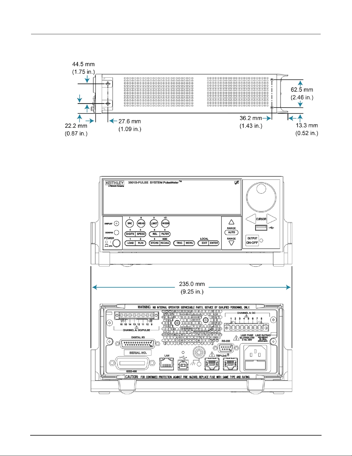
2601B-PULSE weights and dimensions
The instrument weighs 5.9 kg (13 lb) without the 2601B-P-INT attached. With the 2601B-P-INT
attached, it weighs 6.4 kg (14 lb).
The following figure shows the mounting screw locations and dimensions. The dimensions shown are
typical for both sides of the instrument.
For front mounting, use #8-32 × 3/8 in. Phillips pan-head screws. For rear mounting, use
#10-32 × 3/8 in. Phillips pan-head SEMS screws.
Section 2
Installation
Section 2: Installation Model 2601B-PULSE System SourceMeter® Instrument User's Manual
2-2 2601B-PULSE-900-01 Rev. A August 2021
Figure 1: Mounting screw locations and dimensions
The following figures show the dimensions when the handle is installed.
Figure 2: 2601B-PULSE dimensions front and rear with handle
Model 2601B-PULSE System SourceMeter® Instrument User's Manual Section 2: Installation
2601B-PULSE-900-01 Rev. A August 2021 2-3
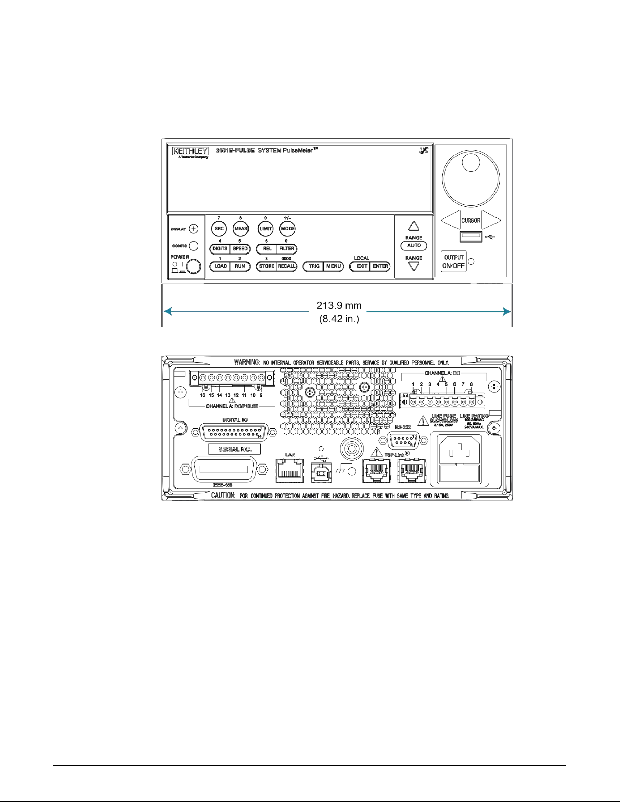
The following figures show the dimensions when the handle has been removed.
Figure 3: 2601B-PULSE front and rear panel dimensions with handle removed
Section 2: Installation Model 2601B-PULSE System SourceMeter® Instrument User's Manual
2-4 2601B-PULSE-900-01 Rev. A August 2021
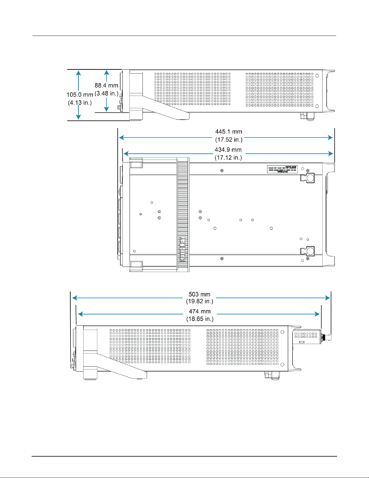
Figure 4: 2601B-PULSE height and length
Figure 5: 2601B-PULSE with 2601B-P-INT length

Model 2601B-PULSE System SourceMeter® Instrument User's Manual Section 2: Installation
2601B-PULSE-900-01 Rev. A August 2021 2-5
Preparing the instrument for rack mounting
To remove the handle, mounting ears, and rear feet:
1. Gently pull the handle (1) away from the sides of the instrument case and swing it up or down
until the orientation arrows on the handles line up with the orientation arrows on the two mounting
ears, as shown in the following figure.
Figure 6: Rack-mount kit handle removal
2. After you align the arrows (2), pull the ends of the handle (1) away from the case.
3. Remove the screws that secure the two mounting ears (3).
4. Pull down and out to remove each ear.
Figure 7: Mounting ear removal
5. From the bottom of the instrument, pull out the two rubber feet and remove the two screws (4).
For the locations, see the following figure.
Figure 8: Instrument rubber feet removal
Store the handle, rubber feet, and hardware for future use.
Section 2: Installation Model 2601B-PULSE System SourceMeter® Instrument User's Manual
2-6 2601B-PULSE-900-01 Rev. A August 2021
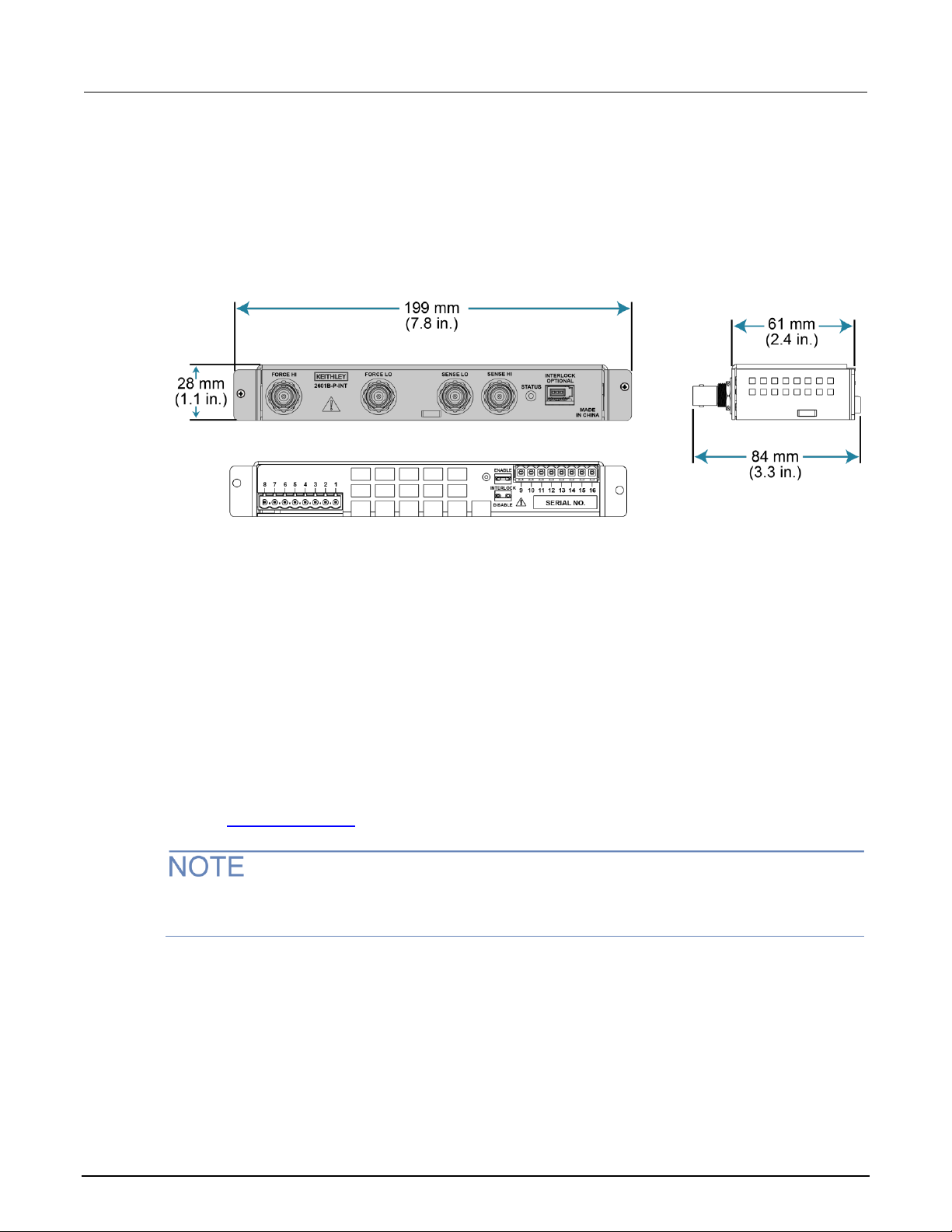
2601B-P-INT dimensions
The following figure show the dimensions of the 2601B-P-INT Interlock and Cable Connector Box.
The 2601B-P-INT weighs 0.5 kg (1 lb).
Figure 9: 2601B-P-INT dimensions
Installing the 2601B-P-INT
The 2601B-PULSE is shipped with the 2601B-P-INT Rear Panel Interlock and Cable Connector Box
accessory. The 2601B-P-INT:
• Simplifies test connections to the 2601B-PULSE by converting terminal strip connections to
standard BNC connectors
• Makes the connections between the CHANNEL A: DC and CHANNEL A: DC/PULSE
terminal strips
• Provides connections for an optional interlock
Refer to Using the interlock (on page 2-37) for detail on connecting the interlock.
You must use the screws that are provided with the 2601B-P-INT to attach it to the instrument. The
screws that you remove from the instrument will not provide a secure connection.
Model 2601B-PULSE System SourceMeter® Instrument User's Manual Section 2: Installation
2601B-PULSE-900-01 Rev. A August 2021 2-7
To install the 2601B-P-INT:
1. Remove power connections from the 2601B-PULSE.
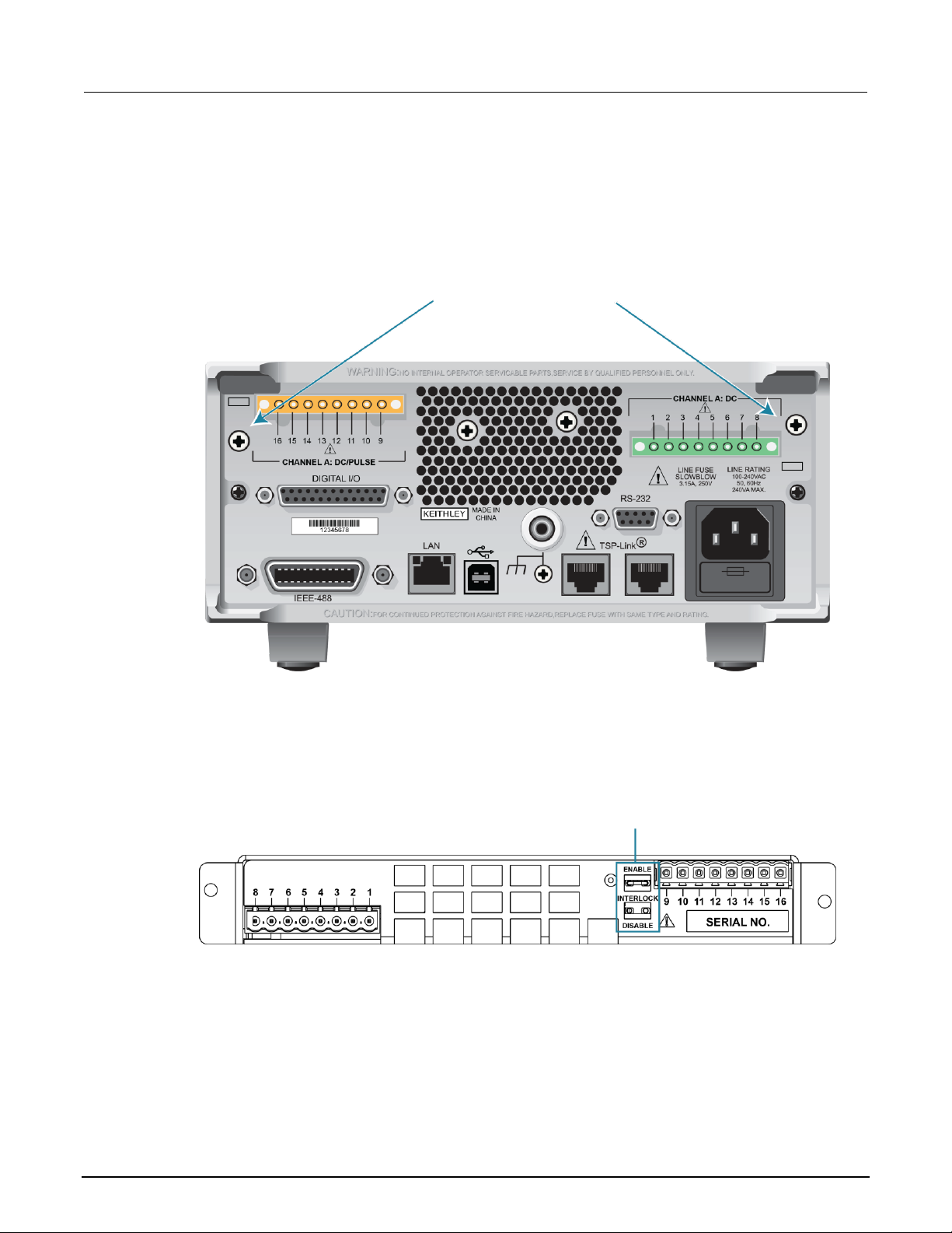
2. On the rear panel of the 2601B-PULSE, remove the screws to the left of the CHANNEL A:
DC/PULSE terminal strip and to the right of the CHANNEL A: DC terminal strip. Save the screws
for operation with the 2601B-P-INT uninstalled. Screw locations are shown in the following figure.
Figure 10: Remove screws from 2601B-PULSE rear panel
3. On the terminal strip panel of the 2601B-P-INT, position the INTERLOCK jumper. Use
needle-nose pliers to position the jumper in the ENABLE slot if you are using an interlock or
DISABLE if you are not using the interlock. The INTERLOCK jumper is shown in the following
figure.
Figure 11: INTERLOCK jumper on the 2601B-P-INT Interlock Box terminal strip panel
4. Align the terminal strip panel of the 2601B-P-INT to the terminal strips on the rear panel of the
2601B-PULSE.
5. Press the 2601B-P-INT connections firmly onto the terminal strips on the rear panel of
the 2601B-PULSE.

Section 2: Installation Model 2601B-PULSE System SourceMeter® Instrument User's Manual
2-8 2601B-PULSE-900-01 Rev. A August 2021
6. Use the screws provided with the 2601B-P-INT to secure it to the rear panel of the
2601B-PULSE.
Figure 12: Installation of the 2601B-P-INT
Replacement jumpers are available from Keystone Electronics Corp., part number 1430-1,
Uninsulated Shorting Pin.
Cooling vents
The 2601B-PULSE has side and top intake and rear exhaust vents. One side must be unobstructed
to dissipate heat.
Excessive heat could damage the 2601B-PULSE and degrade its performance. Only operate the
2601B-PULSE in an environment where the ambient temperature does not exceed 50 °C.
Do not place a container of liquid (water or coffee, for instance) on the top cover. If it spills, the liquid
may enter the case through the vents and cause severe damage.

Model 2601B-PULSE System SourceMeter® Instrument User's Manual Section 2: Installation
2601B-PULSE-900-01 Rev. A August 2021 2-9
To prevent damaging heat build-up and ensure specified performance, use the
following guidelines.
The rear exhaust vent and either the top or both side intake vents must be unobstructed to
properly dissipate heat. Even partial blockage could impair proper cooling.
Do not position any devices adjacent to the 2601B-PULSE that force air (heated or unheated)
toward its cooling vents or surfaces. This additional airflow could compromise accuracy.
When rack mounting the 2601B-PULSE, make sure there is adequate airflow around both
sides to ensure proper cooling. Adequate airflow enables air temperatures within
approximately one inch of the 2601B-PULSE surfaces to remain within specified limits under
all operating conditions.
If high power dissipation equipment is rack mounted next to the 2601B-PULSE, it could cause
excessive heating. To produce specified 2601B-PULSE accuracies, maintain the specified
ambient temperature around the surfaces of the 2601B-PULSE. In rack configurations with
convection cooling only, proper cooling practice places the hottest non-precision equipment
(for example, the power supply) at the top of the rack away from and above precision
equipment (such as the 2601B-PULSE).
Mount precision equipment as low as possible in the rack, where temperatures are coolest.
You can add space panels above and below the 2601B-PULSE to help provide
adequate airflow.
Turning the instrument on and off
The 2601B-PULSE operates from a line voltage of 100 V to 240 V at a frequency of 50 Hz or 60 Hz.
Line voltage is automatically sensed (there are no switches to set). Make sure the operating voltage
in your area is compatible.
Follow the procedure below to connect the 2601B-PULSE to line power and turn on the instrument.
Operating the instrument on an incorrect line voltage may cause damage to the instrument,
possibly voiding the warranty.
Section 2: Installation Model 2601B-PULSE System SourceMeter® Instrument User's Manual
2-10 2601B-PULSE-900-01 Rev. A August 2021
To turn a 2601B-PULSE on and off:
1. Before plugging in the power cord, make sure that the front-panel POWER switch is in the off (O)
position.
2. Connect the female end of the supplied power cord to the ac receptacle on the rear panel.
3. Connect the other end of the power cord to a grounded ac outlet.
The power cord supplied with the 2601B-PULSE contains a separate protective earth (safety
ground) wire for use with grounded outlets. When proper connections are made, the
instrument chassis is connected to power-line ground through the ground wire in the power
cord. In addition, a chassis ground connection is provided through a screw on the rear panel.
This terminal should be connected to a known protective earth. In the event of a failure, not
using a properly grounded protective earth and grounded outlet may result in personal injury
or death due to electric shock.
Do not replace detachable mains supply cords with inadequately rated cords. Failure to use
properly rated cords may result in personal injury or death due to electric shock.
Hazardous voltages may be present in the test system. To prevent injury or death, remove
power from the instrument or test system and discharge any energy storage components (for
example, capacitors or cables) before changing any connections that might allow contact
with an uninsulated conductor.
On some sensitive or easily damaged devices under test (DUTs), the instrument power-up and
power-down sequence can apply transient signals to the DUT that may affect or damage it. When
testing this type of DUT, do not make final connections to it until the instrument has completed its
power-up sequence and is in a known operating state. When testing this type of DUT, disconnect it
from the instrument before turning the instrument off.
To prevent any human contact with a live conductor, connections to the DUT must be fully insulated
and the final connections to the DUT must only use safety-rated safety-jack-socket connectors that
do not allow bodily contact.
4. To turn your instrument on, press the front-panel POWER switch to place it in the on (I) position.
5. To turn your instrument off, press the front-panel POWER switch to place it in the off (O) position.

Model 2601B-PULSE System SourceMeter® Instrument User's Manual Section 2: Installation
2601B-PULSE-900-01 Rev. A August 2021 2-11
Placing a 2601B-PULSE in standby
Hazardous voltages may be present on all output and guard terminals. To prevent electrical
shock that could cause injury or death, never make or break connections to the 2601B-PULSE
while the instrument is powered on. Turn off the equipment from the front panel or
disconnect the main power cord from the rear of the 2601B-PULSE before handling cables.
Putting the equipment into standby does not guarantee that the outputs are powered off if a
hardware or software fault occurs.
When the instrument is on, the output may be placed in an active output state (output on) or a
standby mode (output off). From the front panel, pressing the OUTPUT ON/OFF control toggles the
output using the present instrument configuration. You can also place the output in standby over the
remote interface by sending the following command:
smua.source.output = smua.OUTPUT_OFF
Even though the instrument is placed in standby, the output may not actually be off.
Warmup period
The 2601B-PULSE must be turned on and allowed to warm up for at least two hours to achieve
rated accuracies.
Line frequency configuration
The factory configures the 2601B-PULSE to detect the power line frequency automatically at each
power-up. This detected line frequency (either 50 Hz or 60 Hz) is used for aperture
(NPLC) calculations.
In noisy environments, you can manually configure the instrument to match the actual line frequency.
To configure the line frequency from the front panel:
1. Press the MENU key, then turn the navigation wheel to select LINE-FREQ, and then press the
ENTER key.
2. Turn the navigation wheel to select the appropriate frequency and then press the ENTER key. To
configure the instrument to automatically detect line frequency at each power-up, select AUTO.
3. Press the EXIT (LOCAL) key to return to the main display.
To configure the line frequency from a remote interface:
Set the localnode.linefreq or the localnode.autolinefreq attribute. To set the line
frequency to 60 Hz, send:
localnode.linefreq = 60
To configure the instrument to automatically detect line frequency at each power-up:
localnode.autolinefreq = true

Section 2: Installation Model 2601B-PULSE System SourceMeter® Instrument User's Manual
2-12 2601B-PULSE-900-01 Rev. A August 2021
Remote communications interfaces
You can choose from one of several communication interfaces to send commands to and receive
responses from the 2601B-PULSE.
You can control the 2601B-PULSE from only one communications interface at a time. The first
interface on which the instrument receives a message takes control of the instrument. If another
interface sends a message, that interface can take control of the instrument. You may need to enter a
password to change the interface, depending on the setting of interface access.
The 2601B-PULSE automatically detects the type of communications interface (LAN, USB, GPIB, or
RS-232) when you connect to the respective port on the rear panel of the instrument. In most cases,
you do not need to configure anything on the instrument. In addition, you do not need to reboot if you
change the type of interface that is connected.
Remote interface connections
The 2601B-PULSE supports the following remote interfaces:
• USB: Communicate with the instrument over a USB connection.
• LAN: Local area network (LAN) communications provide the flexibility to build scalable and
functional test or data acquisition systems with a large degree of flexibility.
• GPIB: General purpose interface bus is an IEEE-488 instrumentation data bus.
• RS-232: Communicate with the instrument over the serial port or with another instrument using its
serial port.
The 2601B-PULSE can be controlled from only one communication interface at a time. The first
interface from which it receives a message takes control of the instrument. It ignores the other
interfaces until the instrument is returned to local operation.
For more information about the remote interfaces, see:
• USB communications (on page 2-13)
• LAN communications (on page 2-15)
• GPIB operation (on page 2-27)
• RS-232 interface operation (on page 2-31)

Model 2601B-PULSE System SourceMeter® Instrument User's Manual Section 2: Installation
2601B-PULSE-900-01 Rev. A August 2021 2-13
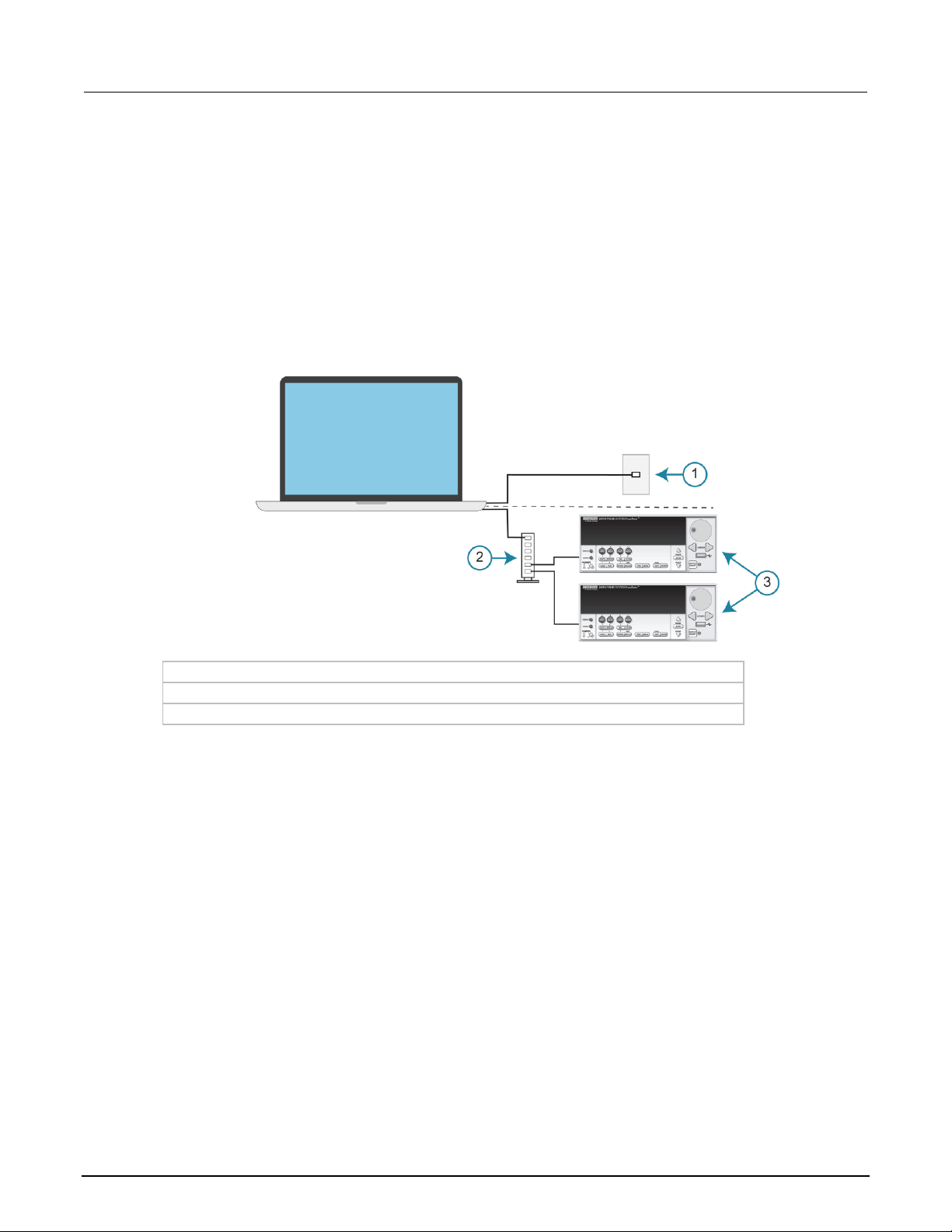
Figure 13: 2601B-PULSE IEEE-488, LAN, USB, and RS-232 connections
1 IEEE-488 connection
2 LAN connection
3 USB connection
4 RS-232 connection
Output queue
Response messages, such as those generated from print commands, are placed in the output queue.
All remote command interfaces share the same output queue.
The output queue sets the message available (MAV) bit in the status model.
The data in the output queue is cleared by the *CLS command.
USB communications
To use the rear-panel USB port, you need a driver that communicates using the USBTMC protocol,
such as NI-VISA, on the host computer.
When installed, the USBTMC protocol allows the Microsoft® Windows® operating system to recognize
the instrument.
When you connect a USB device that implements the USBTMC or USBTMC-USB488 protocol to the
computer, the driver automatically detects the device. Note that the driver does not recognize other
USB devices, such as printers, scanners, and storage devices.
In this section, "USB instruments" refers to devices that implement the USBTMC or
USBTMC-USB488 protocol.
See Software components for applications and instrument drivers (on page 2-34) for more information
on drivers.

Section 2: Installation Model 2601B-PULSE System SourceMeter® Instrument User's Manual
2-14 2601B-PULSE-900-01 Rev. A August 2021
Communicate with the instrument
When using Virtual Instrument Software Architecture (VISA) to communicate with the USB device,
you need to use a VISA communication driver. VISA requires a resource string in the following format
to connect to the correct USB instrument:
USB[board]::manufacturer ID::model code::serial number[::USB interface
number][::INSTR]
This requires that you determine the parameters. You can gather this information by running a utility
that automatically detects all instruments connected to the computer. If you installed the Keithley I/O
Layer, the Keithley Configuration Panel is available from the Microsoft® Windows® Start menu in the
Keithley Instruments menu.
To use the Keithley Configuration Panel to determine the VISA resource string:
1. Start the Keithley Configuration Panel. The Keithley Configuration Wizard opens to the Select
Operation dialog box.
2. Complete the wizard.
3. Save the configuration. From the Configuration Utility, select File > Save.
4. Open the Keithley Communicator.
5. Select File > Open Instrument to open the instrument you named in the wizard.
Figure 14: Keithley Communicator Open an Instrument
6. Select OK.
7. Send a command to the instrument and see if it responds.
If you have a full version of NI-VISA on your system, you can run NI-MAX or the VISA Interactive
Utility. See their documentation for information.
If you have the Keysight IO Libraries on your system, you can run Keysight Connection Expert to
review your USB instruments. See their documentation for information.

Model 2601B-PULSE System SourceMeter® Instrument User's Manual Section 2: Installation
2601B-PULSE-900-01 Rev. A August 2021 2-15
Connecting multiple USB instruments to the computer
The most convenient way to connect USB instrumentation to the computer is to plug a USB cable
directly from the instrument to the computer. If you have more than one USB instrument or have other
USB devices, such as printers, keyboards, and mice, you might not have enough USB connectors on
the computer.
To gain more ports, you can use a USB hub or add more USB controller cards if you have available
PCI or PCI Express slots.
LAN communications
You can communicate with the instrument using a local area network (LAN). The 2601B-PULSE can
connect directly to a host computer or interact with a DHCP or DNS server and other LXI-compliant
instruments on a local area network (LAN). The LAN interface can be used to build flexible test
systems that include web access. This section provides an overview of LAN communications for the
2601B-PULSE.
When you connect using a LAN, you can use a web browser to access the internal web interface of
the instrument and change some of the instrument settings.
There is one LAN port, which is on the rear panel of the instrument, that supports full connectivity on
a 10 Mbps or 100 Mbps network. The 2601B-PULSE automatically detects the speed.
The 2601B-PULSE also supports Multicast DNS (mDNS) and DNS Service Discovery (DNS-SD),
which are useful on a LAN with no central administration.
Contact your network administrator to confirm your specific network requirements before setting up a
LAN connection.
If you have problems setting up the LAN, refer to LAN troubleshooting suggestions (on page 2-25).
The 2601B-PULSE is a Version 1.5 LXI Device Specification 2016 compliant instrument that supports
TCP/IP and complies with IEEE Std 802.3 (ethernet).
LAN cable connection
The 2601B-PULSE includes two LAN crossover cables. One cable is intended for use with the
TSP-Link® network and the other cable is intended for use with the LAN.
However, you can use any standard LAN crossover cable (category 5e, RJ-45, male-to-male) or
straight-through cable to connect your equipment. The instrument automatically senses which cable
you have connected.
Section 2: Installation Model 2601B-PULSE System SourceMeter® Instrument User's Manual
2-16 2601B-PULSE-900-01 Rev. A August 2021
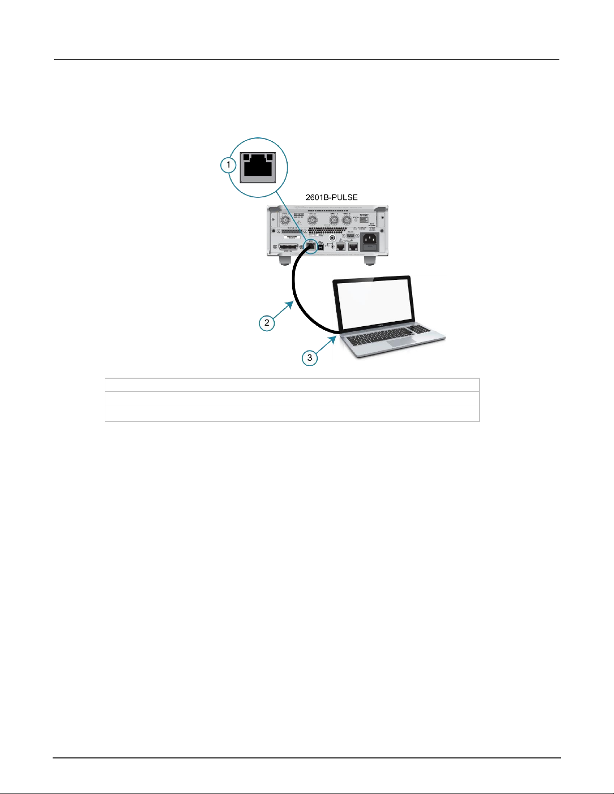
The following figure shows the location of the LAN port on the rear panel of the instrument. Connect
the LAN cable between this connection and the LAN port on the computer.
Figure 15: 2601B-PULSE ethernet connection
1 2601B-PULSE ethernet port (LAN)
2 Straight-through LAN cable or crossover LAN cable
3 Ethernet port (on the host computer)
You can connect the instrument to the LAN in a one-to-one, one-to-many, two network card, or
enterprise configuration, as described in the following topics.
One-to-one connection
With most instruments, a one-to-one connection is done only when you are connecting a single
instrument to a single network interface card.
A one-to-one connection using a network crossover cable connection is similar to a typical RS-232
system using a null modem cable. The crossover cable has its receive (RX) and transmit (TX) lines
crossed to allow the receive line input to be connected to the transmit line output on the network
interfaces.
Model 2601B-PULSE System SourceMeter® Instrument User's Manual Section 2: Installation
2601B-PULSE-900-01 Rev. A August 2021 2-17
The figure below shows a category 5e RJ-35 crossover cable (1) between the instrument and the
computer.
Figure 16: One-to-one connection with a crossover cable
The 2601B-PULSE supports Auto-MDIX and can use either normal LAN CAT-5 cables (patch) or
crossover cables. The instrument automatically adjusts to support either cable.
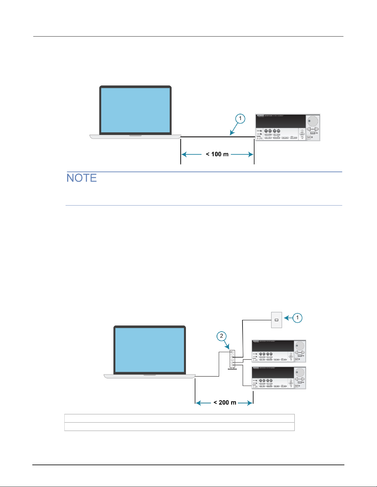
One-to-many connection
With a LAN hub, a single network interface card can be connected to as many instruments as the hub
can support. This requires straight-through network (not crossover) cables for hub connections.
The advantage of this method is easy expansion of measurement channels when the test
requirements exceed the capacity of a single instrument. With only the instruments connected to the
hub, this is an isolated instrumentation network. However, with a corporate network attached to the
hub, the instruments become part of the larger network.
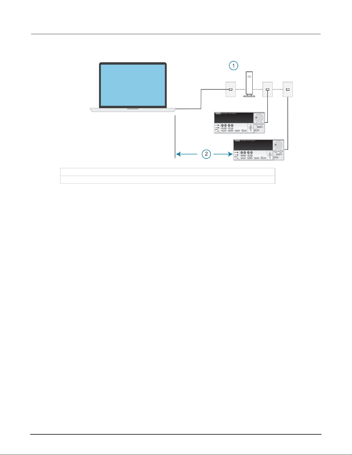
Figure 17: One-to-many connection using a network hub or switch
1 Corporate network
2 Hub
Section 2: Installation Model 2601B-PULSE System SourceMeter® Instrument User's Manual
2-18 2601B-PULSE-900-01 Rev. A August 2021
Two network card connection
If you need to connect independent corporate and instrumentation networks, two network interface
cards are required in the computer controller. Though the two networks are independent, stations on
the corporate network can access the instruments and the instruments can access the corporate
network using the same computer.
This configuration resembles a GPIB setup in which the computer is connected to a corporate
network, but also has a GPIB card in the computer to communicate with instruments.
Figure 18: Two network card connection
1 Corporate network
2 Hub
3 Instrumentation network
Instrumentation connection to enterprise routers or servers
This connection uses an existing network infrastructure to connect instruments to the computer
controller. In this case, you must get the network resources from the network administrator.
Usually, the instruments are kept inside the corporate firewall, but the network administrator can
assign resources that allow them to be outside the firewall. This allows instruments to be connected
to the internet using appropriate security methods. Data collection and distribution can be controlled
from virtually any location.
Model 2601B-PULSE System SourceMeter® Instrument User's Manual Section 2: Installation
2601B-PULSE-900-01 Rev. A August 2021 2-19
Figure 19: Instrumentation connection to enterprise routers or servers
1 Enterprise-wide or internet (routers or servers)
2 Limited by network size
Set up LAN communications on the instrument
The following topics describe how to check the existing LAN communications settings and set up
manual or automatic LAN communications.
Check communications settings
Before configuring the LAN, you can check the communications settings on the instrument without
making any changes.
To view the active network settings:
1. From the front panel, press the MENU key, and then select LAN > STATUS.
2. Use the navigation wheel to select one of the following network settings:
▪ IP-ADDRESS
▪ GATEWAY
▪ SUBNET-MASK
▪ METHOD
▪ DNS
▪ MAC-ADDRESS
3. Press the ENTER key to view the active setting.
4. Press the EXIT (LOCAL) key once to return to the STATUS menu.

Section 2: Installation Model 2601B-PULSE System SourceMeter® Instrument User's Manual
2-20 2601B-PULSE-900-01 Rev. A August 2021
Set up automatic LAN configuration
If you are connecting to a LAN that has a DHCP server or if you have a direct connection between the
instrument and a host computer, you can use automatic IP address selection.
If you select Auto, the instrument attempts to get an IP address from a DHCP server. If this fails, it
reverts to an IP address in the range of 169.254.1.0 through 169.254.254.255.
Both the host computer and the instrument should be set to use automatic LAN configuration.
Though it is possible to have one set to manual configuration, it is more complicated to set up.
To set up automatic IP address selection using the front panel:
1. From the front panel, press the MENU key, and then select LAN > CONFIG > METHOD.
2. Select AUTO.
3. Press the ENTER key.
4. Press the EXIT (LOCAL) key until you return to the LAN CONFIG menu.
5. Select APPLY_SETTINGS > YES, and then press the ENTER key.
Set up manual LAN configuration
These steps assume that you are making all the settings in the order shown here. If you only change
one or a few settings, you need to apply the settings before they take effect. To apply the settings,
from the LAN CONFIG menu, select APPLY_SETTINGS > YES, and then press the ENTER key.
Contact your corporate information technology (IT) department to secure a valid IP address for the
instrument when placing the instrument on a corporate network.
To set up the LAN configuration manually using the front panel:
1. Press the MENU key to display the MAIN MENU.
2. Use the navigation wheel to select LAN. The LAN CONFIG menu is displayed.
3. Select CONFIG > METHOD > MANUAL and then press the ENTER key.
4. Press the EXIT (LOCAL) key once to return to the LAN CONFIG menu.
5. Select CONFIG > IP-ADDRESS.
6. Turn the navigation wheel to select and enter a valid IP address for the instrument.
The IP address of the instrument can have leading zeros, but the IP address of the computer cannot.

Model 2601B-PULSE System SourceMeter® Instrument User's Manual Section 2: Installation
2601B-PULSE-900-01 Rev. A August 2021 2-21
7. Press the ENTER key to confirm the changes.
8. Press the EXIT (LOCAL) key twice to return to the LAN CONFIG menu.
9. Select CONFIG > GATEWAY.
10. Turn the navigation wheel to select and enter a valid gateway address for the instrument.
11. Press the ENTER key to confirm the changes.
12. Press the EXIT (LOCAL) key twice to return to the LAN CONFIG menu.
13. Select CONFIG > SUBNETMASK.
14. Turn the navigation wheel to select and enter a valid subnet mask for the instrument.
15. Press the ENTER key to confirm the changes.
16. Press the EXIT (LOCAL) key twice to return to the LAN CONFIG menu.
17. Select APPLY_SETTINGS > YES, and then press the ENTER key.
LAN speeds
Another characteristic of the LAN is speed. The 2601B-PULSE negotiates with the host computer and
other LXI-compliant devices on the LAN to transmit data at the highest speed possible. LAN speeds
must be configured to match the speed of the other instruments on the network.
To set the LAN speed:
1. From the front panel, press the MENU key and select LAN > CONFIG > SPEED.
2. Turn the navigation wheel to select either 10 Mbps or 100 Mbps.
3. Press the ENTER key.
4. Press the EXIT (LOCAL) key once to return to the previous menu.
5. Select APPLY_SETTINGS > YES, and then press the ENTER key.
Configuring the domain name system (DNS)
The Domain Name System (DNS) lets you type a domain name in the address bar to connect to the
instrument. If you use DNS, you can use a name instead of an IP address.
Example:
Model2601B-PULSE.XYZcompany.com
Contact your corporate information technology (IT) department for information about DNS. If a DNS
server is not part of the LAN infrastructure, do not use this setting.

Section 2: Installation Model 2601B-PULSE System SourceMeter® Instrument User's Manual
2-22 2601B-PULSE-900-01 Rev. A August 2021
To enable or disable DNS host name verification:
1. From the front panel, press the MENU key, and then select LAN > CONFIG > DNS > VERIFY.
2. Turn the navigation wheel to select either ENABLE or DISABLE. When enabled, the instrument
performs a DNS lookup to verify the DNS host name matches the value specified in the
lan.config.dns.hostname attribute.
3. Press the ENTER key.
4. Press the EXIT (LOCAL) key twice to return to the LAN CONFIG menu.
To enable or disable DNS registration:
1. From the front panel, press the MENU key and select LAN > CONFIG > DNS > DYNAMIC.
2. Turn the navigation wheel to select either ENABLE or DISABLE. DNS registration works with the
DHCP to register the host name specified in the lan.config.dns.hostname attribute with the
DNS server.
3. Press the ENTER key.
4. Press the EXIT (LOCAL) key twice to return to the LAN CONFIG menu.
5. Select APPLY_SETTINGS > YES, and then press the ENTER key.
To set the DNS server IP addresses:
1. From the front panel, press the MENU key and select LAN > CONFIG > DNS.
2. Turn the navigation wheel to select either DNS-ADDRESS1 or DNS-ADDRESS2.
3. Press the ENTER key.
4. Turn the navigation wheel to select and enter a valid IP address for the DNS server.
5. Press the ENTER key.
6. Press the EXIT (LOCAL) key twice to return to the LAN CONFIG menu.
7. Select APPLY_SETTINGS > YES, and then press the ENTER key.
Confirming the active speed and duplex negotiation
The 2601B-PULSE automatically detects the speed and duplex negotiation active on the LAN. Once
the speed and duplex negotiation is detected, the instrument automatically adjusts its own settings to
match the LAN settings.
To confirm the active LAN speed and duplex mode:
1. From the front panel, press the MENU key.
2. Select LAN > STATUS.
3. Use the navigation wheel to select one of the following:
▪ SPEED
▪ DUPLEX
4. Press the ENTER key to view the active setting.
5. Press the EXIT (LOCAL) key once to return to the STATUS menu.

Model 2601B-PULSE System SourceMeter® Instrument User's Manual Section 2: Installation
2601B-PULSE-900-01 Rev. A August 2021 2-23
To set the duplex mode:
1. From the front panel, press the MENU key and select LAN > CONFIG > DUPLEX.
2. Turn the navigation wheel to select either HALF or FULL.
3. Press the ENTER key.
4. Press the EXIT (LOCAL) key once to return to the LAN CONFIG menu.
5. Select APPLY_SETTINGS > YES, and then press the ENTER key.
Use the LXI Discovery Tool
To find the IP address of the 2601B-PULSE from a computer, use the LXI Discovery Tool, a utility that
is available from the Resources tab of the LXI Consortium website (lxistandard.org).
LAN status LEDs
The figure below illustrates the two status light-emitting diodes (LEDs) that are on the LAN port of the
instrument. The table below the figure provides explanations of the LED states. The LED labeled 1
indicates the LAN port is connected to a 100 Mbps network. The LED labeled 2 indicates the LAN
port is connected to a 10 Mbps network.
Figure 20: LAN status
When an LED is:
The network:
Off
is not connected
On
is connected
Blinking
is sending or receiving data
Selecting a LAN interface protocol
You can use a remote interface protocol to connect to the 2601B-PULSE. The 2601B-PULSE
provides Telnet, VXI-11, and raw socket LAN interfaces, with associated LAN protocols (each
interface uses a different protocol). Select the interface based on the protocol needed.
You can also use a dead socket termination interface (DST) to troubleshoot connection problems.
You can only use one remote interface at a time. Although multiple ethernet connections to the
instrument can be opened, only one can be used to control the instrument at a time.

Section 2: Installation Model 2601B-PULSE System SourceMeter® Instrument User's Manual
2-24 2601B-PULSE-900-01 Rev. A August 2021
Telnet connection
The Telnet protocol is similar to raw socket and can be used when you need to interact directly with
the instrument. Telnet is often used for debugging and troubleshooting. You need a separate Telnet
program to use this protocol.
The 2601B-PULSE supports the Telnet protocol, which you can use over a TCP/IP connection to
send commands to the instrument. You can use a Telnet connection to interact with scripts or send
real-time commands.
VXI-11 connection
This remote interface is similar to GPIB and supports message boundaries, serial poll, and service
requests (SRQs). A VXI-11 driver or NI-VISA software is required. Test Script Builder (TSB) uses
NI-VISA and can be used with the VXI-11 interface. You can expect a slower connection with
this protocol.
Raw socket connection
All Keithley instruments that have LAN connections support raw socket communication. This means
that you can connect to the TCP/IP port on the instrument and send and receive commands. A
programmer can easily communicate with the instrument using the Winsock API on computers with
the Microsoft® Windows® operating system or using the Berkeley Sockets API on Linux® or
Apple® computers.
Raw socket is a basic ethernet connection that communicates in a manner similar to RS-232 without
explicit message boundaries. The instrument always terminates messages with a line feed, but
because binary data may include bytes that resemble line-feed characters, it may be difficult to
distinguish between data and line-feed characters.
Use raw socket as an alternative to VXI-11. Raw socket offers a faster connection than VXI-11.
However, raw socket does not support explicit message boundaries, serial poll, and service requests.
Dead socket connection
The dead socket termination (DST) port is used to terminate all existing ethernet connections. A dead
socket is a socket that is held open by the instrument because it has not been properly closed. This
most often happens when the host computer is turned off or restarted without first closing the socket.
This port cannot be used for command and control functions.
Use the dead socket termination port to manually disconnect a dead session on any open socket. All
existing ethernet connections are terminated and closed when the connection to the dead socket
termination port is closed.

Model 2601B-PULSE System SourceMeter® Instrument User's Manual Section 2: Installation
2601B-PULSE-900-01 Rev. A August 2021 2-25
Confirming port numbers
To view the port number assigned to each remote interface protocol:
1. From the front panel, press the MENU key, and then select LAN > STATUS > PORT.
2. Use the navigation wheel to select one of the following:
▪ RAW-SOCKET
▪ TELNET
▪ VXI-11
▪ DST
3. Press the ENTER key to view the port number.
4. Press the EXIT (LOCAL) key once to return to the PORT menu.
The following table displays the remote interface protocols supported by the 2601B-PULSE and their
assigned port numbers.
Port number
Command interface
Port number
Raw socket
5025
Telnet
23
VXI-11
1024
DST (dead socket termination)
5030
Reset LAN settings
To reset the LAN settings to the factory defaults from the front panel, select MENU > LAN > RESET.
LAN troubleshooting suggestions
If you are unable to connect to the web interface of the instrument, check the following items:
• The network cable is in the LAN port on the rear panel of the instrument, not one of the
TSP-Link® ports.
• The network cable is in the correct port on the computer. The LAN port of a laptop may be
disabled when the laptop is in a docking station.
• The setup procedure used the configuration information for the correct ethernet card.
• The network card of the computer is enabled.
• The IP address of the instrument is compatible with the IP address on the computer.
• The subnet mask address of the instrument is the same as the subnet mask address of
the computer.
You can also try restarting the computer and the instrument.
To restart the instrument:
1. Turn the power to the instrument off, and then on.
2. Wait at least 60 seconds for the network configuration to be completed.

Section 2: Installation Model 2601B-PULSE System SourceMeter® Instrument User's Manual
2-26 2601B-PULSE-900-01 Rev. A August 2021
Access the instrument web interface
To access the instrument web interface:
1. Open a web browser on the host computer.
2. Enter the IP address of the instrument in the web browser address box. For example, if the
instrument IP address is 192.168.1.101, enter 192.168.1.101 in the browser address box.
3. Press Enter on the computer keyboard to open the instrument web interface.
If the web interface does not open in the browser, see LAN troubleshooting suggestions (on
page 2-25).
Viewing LAN status messages
To view the LAN status messages:
1. From the front panel, press the MENU key and select LAN > STATUS > CONFIG/FAULT.
2. Press the ENTER key.
Figure 21: LAN CONFIG/FAULT
There are two types of LAN status messages:
• LAN fault messages: Communicate issues related to physical connectivity.
• LAN configuration messages: Communicate issues or events related to configuration.
The following table displays possible fault and configuration messages.
LAN CONFIG/FAULT messages
LAN message type
Possible messages
LAN fault
Could not acquire IP address
Duplicate IP address detected
DHCP lease lost
Lan Cable Disconnected
LAN configuration
Starting DHCP Configuration
DHCP Server Not Found
DHCP configuration started on xxx.xxx.xxx.xxx
Searching for DNS server(s)
Starting DLLA Configuration
DLLA Failed
DLLA configuration started on xxx.xxx.xxx.xxx
Starting Manual Configuration
Manual configuration started on xxx.xxx.xxx.xxx
Closed
Model 2601B-PULSE System SourceMeter® Instrument User's Manual Section 2: Installation
2601B-PULSE-900-01 Rev. A August 2021 2-27
Monitoring the LAN
The lan.autoconnect command configures the instrument to monitor the LAN for lost connections.
All ethernet connections are disconnected if the LAN link is disconnected for longer than the time-out
value specified in the lan.linktimeout attribute.
GPIB operation
The following topics contain information about GPIB standards, bus connections, and primary
address selection.
GPIB standards
The GPIB is the IEEE-488 instrumentation data bus, which uses hardware and programming
standards originally adopted by the Institute of Electrical and Electronic Engineers (IEEE) in 1975.
The instrument is IEEE Std 488.1 compliant and supports IEEE Std 488.2 common commands and
status model topology.
Connect the GPIB cable
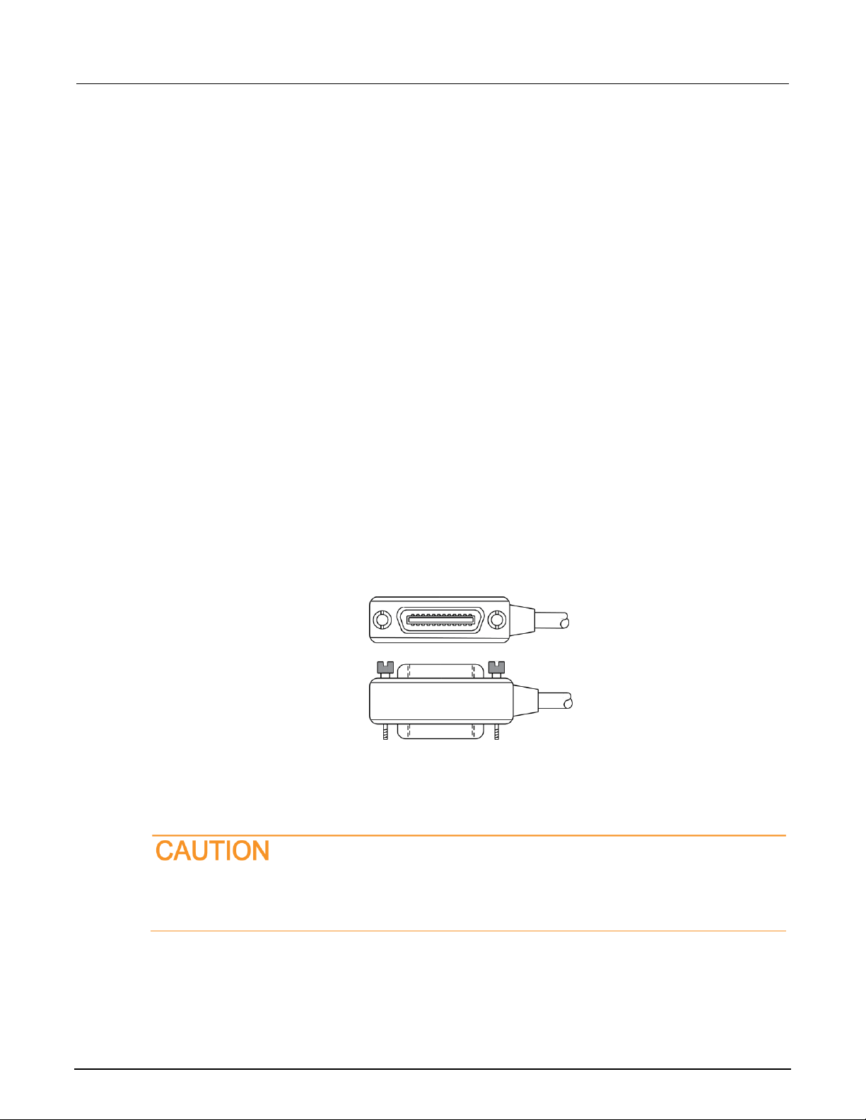
To connect an instrument to the GPIB bus, use a cable equipped with standard IEEE-488 connectors,
as shown below.
Figure 22: GPIB connector
To allow many parallel connections to one instrument, stack the connectors. Each connector has two
screws on it to ensure that connections remain secure. The figure below shows a typical connection
diagram for a test system with multiple instruments.
To avoid possible mechanical damage, stack no more than three connectors on any one
instrument. To minimize interference caused by electromagnetic radiation, use only shielded
IEEE-488 cables. Contact Keithley Instruments for shielded cables.

Section 2: Installation Model 2601B-PULSE System SourceMeter® Instrument User's Manual
2-28 2601B-PULSE-900-01 Rev. A August 2021
Figure 23: IEEE-488 connections
To connect the instrument to the IEEE-488 bus, line up the cable connector with the connector on the
rear panel. Install and tighten the screws securely, making sure not to overtighten them. Refer to
Remote interface connections (on page 2-12) for the location of the connector.
Connect any additional connectors from other instruments as required for your application. Make sure
the other end of the cable is properly connected to the controller. You can have up to 15 devices
connected to a GPIB interface, including the controller. The maximum cable length is the lesser
of either:
• The number of devices multiplied by 2 m (6.5 ft)
• 20 m (65.6 ft)
You may see erratic bus operation if you ignore these limits.
Primary address
The 2601B-PULSE ships from the factory with a GPIB primary address of 26. If the GPIB interface is
enabled, it momentarily displays the primary address on power-up. You can set the address to a
value from 0 to 30, but do not assign the same address to another device or to a controller that is on
the same GPIB bus (controller addresses are usually 0 or 21).
To set or check the primary address from the front panel:
1. Press the MENU key, select GPIB, and then press the ENTER key or the navigation wheel.
2. Select ADDRESS, then press the ENTER key or the navigation wheel.
3. Use the navigation wheel to set the primary address to the appropriate value, then press the
ENTER key or the navigation wheel.
4. Press the EXIT (LOCAL) key twice to return to the normal display.

Model 2601B-PULSE System SourceMeter® Instrument User's Manual Section 2: Installation
2601B-PULSE-900-01 Rev. A August 2021 2-29
To set the primary address remotely:
gpib.address = address
To set the primary address remotely to 20:
gpib.address = 20
Note that changing the GPIB address takes effect when the command is processed. Any response
messages generated after processing this command are sent with the new settings. If command
messages are being queued (sent before this command has executed), the new settings may take
effect in the middle of a subsequent command message, so be careful when setting this attribute from
the GPIB interface.
GPIB terminator
When receiving data over the GPIB, the instrument terminates messages on any line feed character
or any data byte with EOI asserted (line feed with EOI asserted is also valid). When sending data, it
appends a line feed character to all outgoing messages. The EOI line is asserted with the terminating
line feed character.
Front-panel GPIB operation
This section describes aspects of the front panel that are part of GPIB operation, including messages,
status indicators, and the LOCAL key.
Error and status messages
The front-panel display may show error and status messages (see Displayed error and status
messages (on page 3-14)). The instrument can be programmed to generate a service request (SRQ),
and command queries can be performed to check for specific error conditions.
Communication status indicators
The remote (REM), talk (TALK), listen (LSTN), and service request (SRQ) indicators show the
communication bus status. Each of these indicators is described in the following table.
Status indicator
Applies to
REM
GPIB, VXI-11, USB, RS-232
TALK
GPIB only
LSTN
GPIB only
SRQ
GPIB, VXI-11, USB
REM
This indicator is illuminated when the instrument is in the remote-control state. When the instrument is
in the remote-control state, all front-panel keys, except for the EXIT (LOCAL) key and OUTPUT
ON/OFF control, are locked out. When REM is off, the instrument is in the local-control state and
front-panel operation is restored.

Section 2: Installation Model 2601B-PULSE System SourceMeter® Instrument User's Manual
2-30 2601B-PULSE-900-01 Rev. A August 2021
TALK
This indicator is on when the instrument is in the talker active state. Place the instrument in the talk
state by addressing it to talk with the correct talk command. TALK is off when the instrument is in the
talker idle state. Place the instrument in the talker idle state by sending a UNT (untalk) command,
addressing it to listen, or by sending the IFC (interface clear) command.
LSTN
This indicator is on when the instrument is in the listener active state, which is activated by
addressing the instrument to listen with the correct listen command. LSTN is off when the instrument
is in the listener idle state. Place the instrument in the listener idle state by sending UNL (unlisten),
addressing it to talk, or by sending the IFC (interface clear) command over the bus.
SRQ
You can program the instrument to generate a service request (SRQ) when one or more errors or
conditions occur. When this indicator is on, a service request was generated. This indicator stays on
until all conditions that caused the SRQ are cleared.
Note that while the SRQ indicator turns on when a service request is generated, it reflects the state of
the master summary status (MSS) bit and not the request for service (RQS) bit. Therefore, performing
a serial poll does not turn off the indicator. To turn off the indicator, you must use *CLS or
status.reset() to clear all the conditions that caused the MSS bit to be set.
The SRQ applies to all available communication buses. However, actual service requests only apply
to GPIB, USB, and VXI-11.
For additional information on using the SRQ, refer to “Status byte and service request (SRQ)” in the
Model 2601B-PULSE Reference Manual.
LOCAL key
The EXIT (LOCAL) key cancels the remote state and restores local operation of the instrument.
Pressing the EXIT (LOCAL) key turns off the REM indicator and returns the display to normal if a
user-defined message was displayed. Pressing the EXIT (LOCAL) key or the OUTPUT ON/OFF
control also aborts any commands or scripts that are being processed.
If the LLO (local lockout setting) command is in effect, the EXIT (LOCAL) key is inoperative. For
safety reasons, you can use the OUTPUT ON/OFF control to turn the output off while in LLO.

Model 2601B-PULSE System SourceMeter® Instrument User's Manual Section 2: Installation
2601B-PULSE-900-01 Rev. A August 2021 2-31
RS-232 interface operation
The following topics contain information about configuring RS-232 communication parameters,
sending or receiving command messages, and requesting or retrieving data. To control the
2601B-PULSE, connect a controller or personal computer to the 2601B-PULSE RS-232 interface.
Alternatively, you can use the 2601B-PULSE to control another device over RS-232.
Setting RS-232 interface parameters
To set interface parameters from the front panel:
1. Press the MENU key, select RS232, and then press the ENTER key or the navigation wheel.
2. Select and enter the following interface parameters:
▪ BAUD: Set baud rate (see Baud rate (on page 2-32))
▪ BITS: Set number of bits (see Data bits and parity (on page 2-32))
▪ PARITY: Set parity
▪ FLOW-CTRL: Set Flow control and signal handshaking (on page 2-32)
▪ ENABLE: Enable or disable the RS-232 interface
3. Press the EXIT (LOCAL) key twice to return to the normal display.
Remote RS-232 parameters
Commands to set RS-232 parameters are listed in the following table.
RS-232 interface commands
Command
Description
serial.baud = baud
Set baud rate (300, 600, 1200, 2400, 4800, 9600, 19200,
38400, 57600, 115200)
serial.databits = bits
Set number of bits (7 or 8)
serial.flowcontrol = flow
Set flow control:
serial.FLOW_NONE (no flow control)
serial.FLOW_HARDWARE (hardware flow control)
serial.parity = parity
Set parity:
serial.PARITY_NONE (no parity)
serial.PARITY_EVEN (even parity)
serial.PARITY_ODD (odd parity)
Changes to a serial port setting take effect when the command is processed. Any response
messages generated after the commands are processed are sent with the new settings. If command
messages are being queued (sent before the commands have executed), the new settings may take
effect in the middle of a subsequent command message, so be careful when setting these attributes
from the RS-232 interface.
RS-232 programming example
The programming example below illustrates how to set the baud rate to 9600 with no flow control:
serial.baud = 9600
serial.flowcontrol = serial.FLOW_NONE

Section 2: Installation Model 2601B-PULSE System SourceMeter® Instrument User's Manual
2-32 2601B-PULSE-900-01 Rev. A August 2021
Sending and receiving data
The RS-232 interface transfers data using 7 or 8 data bits; 1 stop bit; and no, even, or odd parity.
Make sure the device you connect to the 2601B-PULSE also uses the same settings.
RS-232 terminator
When receiving data over the RS-232 interface, the command interface terminates on line feeds. A
line feed is appended to all output messages when the RS-232 interface is used as a command
interface.
Sending data using the serial.write() function does not append a terminator. Be sure to append
the appropriate terminator to the message before sending it.
Baud rate
The baud rate is the rate at which the 2601B-PULSE and the programming terminal communicate.
Select one of the following available rates:
▪ 115200
▪ 9600
▪ 600
▪ 57600
▪ 4800
▪ 300
▪ 38400
▪ 2400
▪ 19200
▪ 1200
The factory-selected baud rate is 9600.
Both the 2601B-PULSE and the programming terminal must be configured for the same baud rate.
Make sure the device connected to the 2601B-PULSE RS-232 port can support the selected
baud rate.
Data bits and parity
The RS-232 interface can be configured to send/receive data that is 7 or 8 bits long using even, odd,
or no parity.
Flow control and signal handshaking
Signal handshaking between the controller and the instrument allows the two devices to communicate
to each other to determine if they are ready to receive data.
The RS-232 interface provides two control lines (request to send and clear to send) for this purpose.
The instrument asserts the RTS signal when it is admissible for the computer to transmit to the
instrument. It sends information to the computer when the CTS signal is asserted by the computer.

Model 2601B-PULSE System SourceMeter® Instrument User's Manual Section 2: Installation
2601B-PULSE-900-01 Rev. A August 2021 2-33
RS-232 connections
Connect the RS-232 serial port of the 2601B-PULSE to the serial port of a computer using a
straight-through RS-232 cable terminated with DB-9 connectors. Do not use a null modem cable. The
serial port uses the transmit (TXD), receive (RXD), CTS and RTS (if flow control is enabled), and
signal ground (GND) lines of the RS-232 standard. The connector location is shown in Remote
communications interfaces (on page 2-12).
If your computer uses a DB-25 connector for the RS-232 interface, you need a standard cable or
adapter with a DB-25 connector on one end and a DB-9 connector on the other.
Figure 24: RS-232 interface connector
RS-232 connector pinout
Pin number
Description
1
Not used
2
TXD, transmit data
3
RXD, receive data
4
Not used
5
GND, signal ground
6
Not used
7
RTS, ready to send
8
CTS, clear to send
9
Not used
The following table provides pinout identification for the 9-pin (DB-9) or 25-pin (DB-25) serial port
connector on the computer.
Computer serial port pinout
Signal*
DB-9 pin number
DB-25 pin number
DCD, data carrier detect
1
8
RXD, receive data
2
3
TXD, transmit data
3
2
DTR, data terminal ready
4
20
GND, signal ground
5
7
DSR, data set ready
6
6
RTS, request to send
7
4
CTS, clear to send
8
5
RI, ring indicator
9
22
* The 2601B-PULSE does not use all RS-232 signals. See Flow control and signal handshaking (on
page 2-32).

Section 2: Installation Model 2601B-PULSE System SourceMeter® Instrument User's Manual
2-34 2601B-PULSE-900-01 Rev. A August 2021
Software components for applications and instrument drivers
The majority of software applications and all instrument drivers from Keithley Instruments depend on
the following software components:
• NI-VISA
• VISA shared components
• IVI shared components
• NI CVI runtime engine
• NI IVI compliance package
• Keithley instrument driver
These software components are available for download from the Product Support and Downloads
web page (tek.com/product-support).
Instrument driver types
There are several different styles of instrument drivers. Keithley Instruments provides the following
instrument drivers for the 2601B-PULSE:
• A native LabVIEW driver
• An IVI-C driver
• An IVI-COM driver
You need to pick the style that best suits the application development environment (ADE) that you are
using. For example, if you are using LabVIEW, pick a native LabVIEW driver. If a native LabVIEW
driver is not available, you can use an IVI-C driver because LabVIEW has the option of creating a
wrapper for the IVI-C driver.
LabVIEW supports IVI-COM drivers, but they are not preferred. However, if they are the only driver
types available for the instrument, they can be used.
If LabWindows/CVI or C/C++ is your programming language, an IVI-C driver is the best option. For
Microsoft® Visual Basic® 6.0 and any .NET language (C#, VB.NET, and so on), an IVI-COM driver is
the best option.
Sometimes instrument vendors do not provide all three driver types. Most languages can
accommodate other driver types, but this is not optimal.
The following sections describe the different driver types in more detail.

Model 2601B-PULSE System SourceMeter® Instrument User's Manual Section 2: Installation
2601B-PULSE-900-01 Rev. A August 2021 2-35
VXIPnP drivers
VXIplug&play (VXIPnP) style drivers are Win32 DLLs that have some standard functions defined by
the IVI Foundation (ivifoundation.org), such as:
• init
• close
• error_message
• reset
• self_test
• read
• initiate
• fetch
• abort
The application programming interface (API) was defined so that users of instruments have a familiar
API from instrument to instrument. There are some basic guidelines when creating APIs for your
instrument, such as using VISA data types and how to construct the CVI hierarchy.
LabVIEW drivers
Native LabVIEW drivers
A native LabVIEWTM driver is a LabVIEW driver that is created using entirely built-in LabVIEW VIs. It
does not make any calls to external DLLs or Library files. This makes the driver portable to all the
platforms and operating systems that LabVIEW and VISA supports (such as Linux® on x86, Mac
OS® X, and Microsoft® Windows®).
LabVIEW driver wrappers
All IVI-C drivers have a function panel file (file name extension .fp) that shows a hierarchy of the
function calls into a DLL. It is a tool that guides a user to select the correct function call in the driver,
because a DLL only has a flat API entry point scheme (unlike COM or .NET).
Any CVI-generated .fp files can be imported into LabVIEW and LabVIEW generates a wrapper for the
DLL. The drawback here is that the driver is dependent on the DLL, which is not portable and is
therefore specific to the Windows operating system.
Getting instrument drivers
To see what drivers are available for your instrument:
1. Go to the Product Support and Downloads web page (tek.com/product-support).
2. Enter the model number of your instrument.
3. Select Software from the list.
4. Select and download the file.
For LabVIEWTM, you can also go to the National Instruments website and search their instrument
driver database.

Section 2: Installation Model 2601B-PULSE System SourceMeter® Instrument User's Manual
2-36 2601B-PULSE-900-01 Rev. A August 2021
Instrument driver examples
All Keithley drivers come with examples written in several programming languages that show you how
to do common tasks with the instruments. The examples are available in the drivers and through
Test Script Builder.
IVI shared components
The IVI shared components are similar in concept to the VISA shared components. The IVI
Foundation provides class drivers for:
• All the supported instruments (DMM, Scope, Fgen, and so on)
• The configuration store
The IVI shared components also create the installation folders and registry keys that all IVI drivers
and support files use for installation.
Interchangeable Virtual Instruments (IVI) style drivers
The IVI Foundation (ivifoundation.org) defined a set of application programming interfaces (APIs) for
instruments, including digital multimeters, arbitrary waveform/function generators, dc power supplies,
ac power supplies, oscilloscopes, switches, spectrum analyzers, RF signal generators, and
power meters.
There are two types of IVI drivers, IVI-COM and IVI-C. IVI-COM drivers use Microsoft® COM
technology to expose driver functionality. IVI-C drivers use conventional Microsoft® Windows® DLLs
to export simple C-based functions.
For more information about IVI drivers and the differences between the COM, C, and .NET interfaces,
see Understanding the Benefits of IVI
(ivifoundation.org/docs/Understanding%20the%20Benefits%20of%20IVI[3].pdf).
NI CVI runtime engine
IVI-C drivers that are created using the National Instruments (NITM) LabWindows/CVI environment
depend on either the CVI runtime DLL (cvirte.dll) or the instrument support runtime DLL
(instrsup.dll). These DLLs must be present on the system for them to run.
NI IVI Compliance Package
The National Instruments (NITM) IVI Compliance Package (ICP) is a software package that contains
IVI class drivers and support libraries that are needed for the development and use of applications
that leverage IVI instrument interchangeability. The IVI Compliance Package also is based on and is
compliant with the latest version of the instrument programming specifications defined by the IVI
Foundation.
The NI ICP installer installs the IVI shared components, CVI runtime engine, and the instrument
support runtime engine.

Model 2601B-PULSE System SourceMeter® Instrument User's Manual Section 2: Installation
2601B-PULSE-900-01 Rev. A August 2021 2-37
Keithley I/O layer
The Keithley I/O Layer (KIOL) is a software package that contains several utilities and drivers. It is
mainly used as a supplement to IVI drivers or application software like Test Script Builder (TSB).
For additional detail on the Keithley I/O layer, including computer requirements and installation
instructions, see the tek.com/keithley website.
Keithley Configuration Panel
The Keithley Configuration Panel is a configuration utility for IVI drivers, similar to NI-MAX. It can also
autodetect USBTMC instruments and LAN instruments that support the VXI-11 protocol.
Keithley Communicator
The Keithley Communicator is a dumb terminal program that uses VISA to communicate with
the instrument.
How to install the Keithley I/O Layer
Before installing, it is a good practice to check the Product Support and Downloads web page
(tek.com/product-support) to verify that you have the latest version of the Keithley I/O Layer.
You can download the Keithley I/O Layer from the Keithley website.
To install the Keithley I/O Layer from the Keithley website:
1. Download the Keithley I/O Layer Software from the Product Support and Downloads web page.
The software is a single compressed file.
2. Run the downloaded file from the temporary directory.
3. Follow the instructions on the screen to install the software.
4. Reboot your computer to complete the installation.
Using the interlock
You can set up an interlock for the 2601B-PULSE through the 2601B-P-INT Interlock and Cable
Connector Box. When properly used, the output of the instrument turns OFF when the safety fixture
switch opens.
The interlock requires a separate safety fixture switch that is wired to the interlock input on the
2601B-P-INT. For the interlock voltage, you can use the +5 V source pins of the 2601B-PULSE digital
I/O port or an external +5 V source.
It also requires use of the Keithley Model CS-1616-3 Safety Interlock Mating Connector, which is
supplied with the instrument. This part is also available from 3M, part number 37103-A165-00E.
See DUT Test Connections (on page 4-7) for important safety information when using a test fixture.
Section 2: Installation Model 2601B-PULSE System SourceMeter® Instrument User's Manual
2-38 2601B-PULSE-900-01 Rev. A August 2021
When an interlock is required for safety, a separate circuit should be provided that meets the
requirements of the application to reliably protect the operator from hazardous conditions.
The digital I/O port is a suitable source for the 5 V required to power the physical interlock
provided by the 2601B-P-INT. Failure to adhere to these guidelines could result in personal
injury or death.
The 2601B-PULSE with the 2601B-P-INT installed provides an optional interlock circuit.
Once engaged, the interlock helps facilitate the safe operation of the instrument in a test
system by prohibiting the output voltage and current when the interlock circuit is opened. Not
using the interlock could expose the operator to hazardous conditions within the test circuit
that could result in personal injury or death.
Interlock operation
You can set up the interlock using the +5 V supply pins on the digital I/O port on the rear panel of the
instrument or by using an external 5 V source. Both methods use the Model 2601B-P-INT Interlock
and Cable Connector Box to make connections.
With either method, relays in the 2601B-P-INT are in a de-energized state until a remote switch is
closed. The de-energized state prevents current from passing to the device under test (DUT) by
keeping the FORCE HI terminal shorted to the FORCE LO terminal. When the external safety switch
closes, current is sourced from a +5 V pin on the digital I/O port or the external power supply, which
energizes the relay and opens the shorting contacts. When the contacts are open, the 2601B-PULSE
can source power to the DUT.
If the remote switch is part of a test fixture, if the lid of the test fixture opens, the relay is closed and
the output of the 2601B-PULSE instrument turns off. When the lid is closed, the relay contacts open
and the output can be turned on.
To use the interlock, you must set the jumper on the rear panel of the 2601B-P-INT to ENABLE. Refer
to Installing the 2601B-P-INT (on page 2-6) for information on setting the jumper.
When the jumper is set to ENABLE, the safety interlock relay immediately requires 5 V to open.
Depending on the availability of the 5 V signal, the short is applied to or removed from the Force HI
and LO terminals on the 2601B-P-INT, regardless of the interlock setting made through the front
panel or by using the remote commands.
To synchronize the operation of the 2601B-PULSE output with the jumper setting of the 2601B-P-INT,
you must also enable the interlock through the front panel or by using the remote commands.

Model 2601B-PULSE System SourceMeter® Instrument User's Manual Section 2: Installation
2601B-PULSE-900-01 Rev. A August 2021 2-39
To enable the interlock through the front panel:
1. Press the CONFIG key.
2. Select the OUTPUT menu item.
3. Select INTERLOCK.
4. Select DISABLE to disable the interlock or ENABLE to enable it.
To enable the interlock using a remote command, send:
smua.interlock.enable = smua.ENABLE
To disable the interlock using a remote command, send:
smua.interlock.enable = smua.DISABLE
Interlock connections through digital I/O port
The following figure shows digital I/O port pin 20 as ground. You can also use pin 15, 16, 17, 18, 19,
or 21 as ground.
The +5 V source is shown as digital I/O port pin 22. You can also use pin 23 or 25 as the +5 V source.
Use a two-conductor low-voltage cable to connect the +5 V source to the low-voltage remote switch.
The recommended cable is 22 AWG (20 AWG maximum) with 1.2 mm to 1.6 mm outer diameter.
Figure 25: Digital I/O port interlock connections
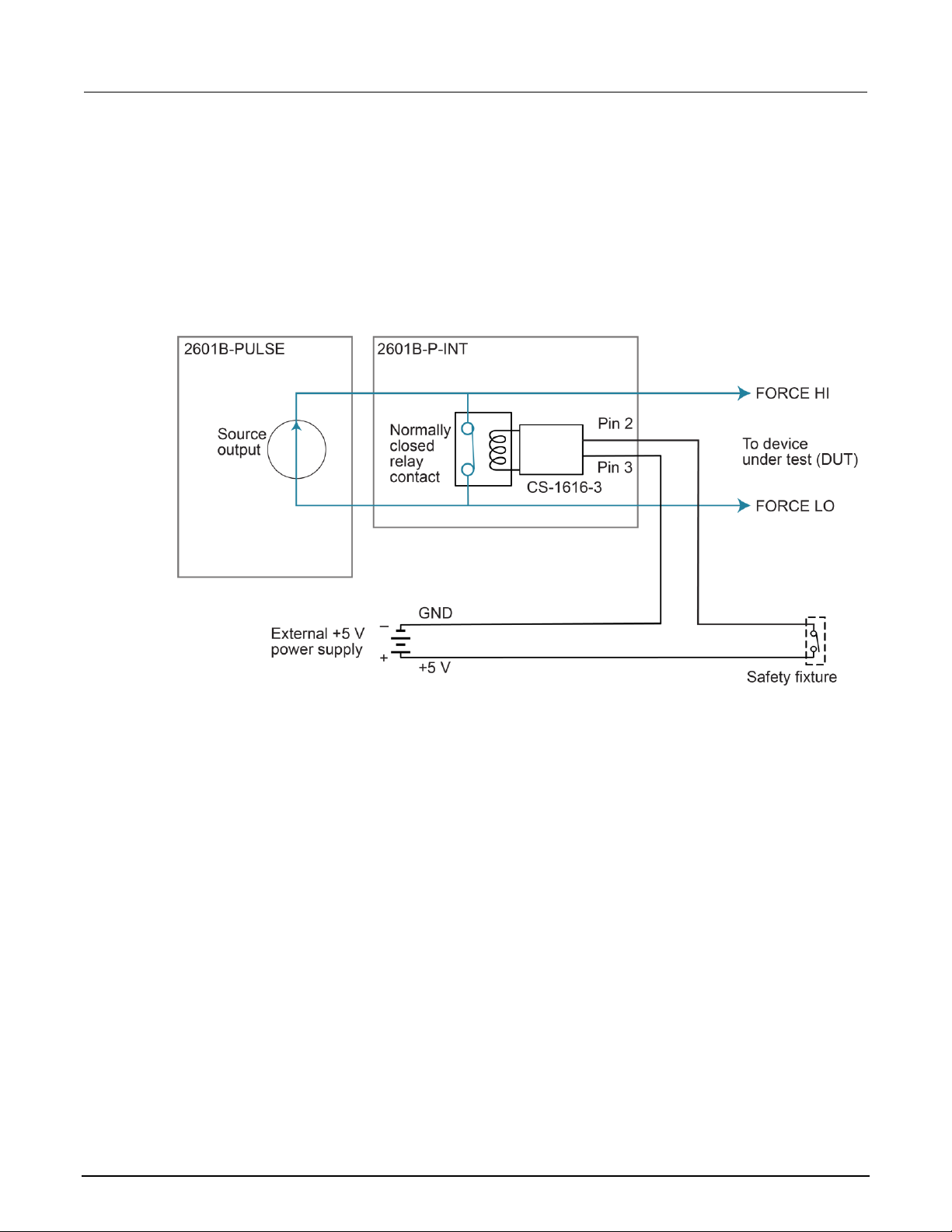
Section 2: Installation Model 2601B-PULSE System SourceMeter® Instrument User's Manual
2-40 2601B-PULSE-900-01 Rev. A August 2021
Interlock connections using external source
Use a +5 V external power supply with a ±5% tolerance. The 2601B-P-INT interlock requires
approximately 125 mA to operate.
Use a two-conductor low-voltage cable to connect the +5 V source to the low-voltage remote switch.
The recommended cable is 22 AWG (20 AWG maximum) with 1.2 mm to 1.6 mm outer diameter.
Figure 26: External source interlock connections
Wiring the interlock mating connector
Use the Keithley Instruments CS-1616-3 Safety Interlock Mating Connector supplied with the
2601B-PULSE to make the interlock connection to the 2601B-P-INT. You must supply connection
wire. When using the CS-1616-3 interlock mating connector with a Keithley instrument, use the
following recommendations for choosing a connection wire:
• Copper alloy
• 7 to 19 bare and tinned strands
• 0.25 mm
2
to 0.50 mm2, 20 AWG to 24 AWG
• Flexible vinyl, semi-flexible vinyl, polyethylene, cross-linked polyethylene, or PTFE
To ensure proper interlock operation, the combined resistance of the external interlock switch and
connection wires must be less than 10 Ω when the switch is closed.

Model 2601B-PULSE System SourceMeter® Instrument User's Manual Section 2: Installation
2601B-PULSE-900-01 Rev. A August 2021 2-41
To assemble the interlock:
1. Insert the wire into the CS-1616-3.
2. Use a pair of pliers to squeeze the connector sections together.
You cannot disassemble and reuse the CS-1616-3.
The interlock pin locations and connections are shown in the following figure. The pins are:
• Pin 3: Earth and chassis ground
• Pin 2: Interlock
• Pin 1 (next to tab): +6 V dc out (current limited)
Figure 27: Interlock mating connector pins
System information
You can retrieve serial number, firmware revision, calibration dates, and memory usage
from the instrument.
To view the system information from the front panel:
1. Press the MENU key.
2. Select SYSTEM-INFO.
3. Select one of the following:
▪ FIRMWARE
▪ SERIAL#
▪ CAL
▪ MEMORY-USAGE

Section 2: Installation Model 2601B-PULSE System SourceMeter® Instrument User's Manual
2-42 2601B-PULSE-900-01 Rev. A August 2021
To retrieve system information from a remote interface:
To retrieve the firmware revision and serial number, send the *IDN? query.
For more information on retrieving system information, see the Model 2601B-PULSE Reference
Manual. In particular:
• To determine memory usage, see the meminfo() function.
• To determine when calibration was last run, see smua.cal.date.
• To determine when calibration is due, see smua.cal.due.
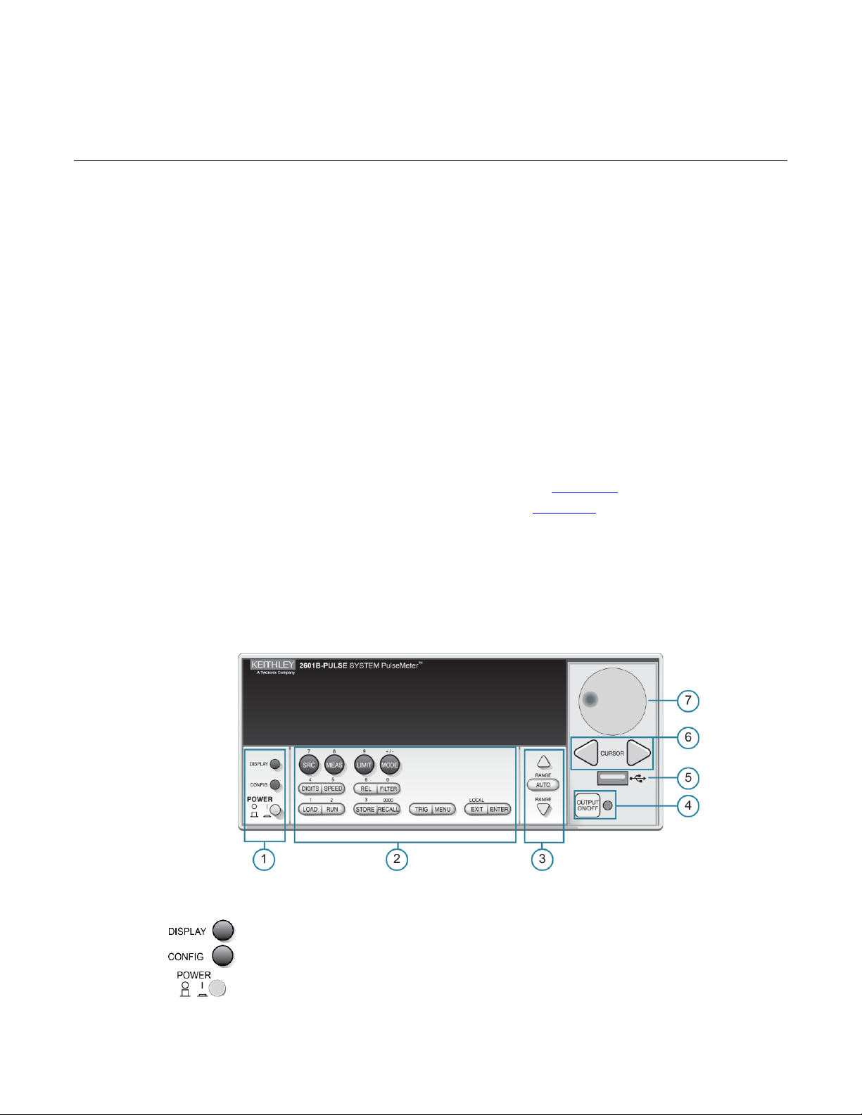
In this section:
Controls, indicators, and connectors ........................................ 3-1
Menu overview ......................................................................... 3-7
Beeper ................................................................................... 3-14
Displayed error and status messages .................................... 3-14
Display operations .................................................................. 3-15
Connecting the USB flash drive ............................................. 3-27
Restoring the factory default setups using remote commands3-28
Using the web interface .......................................................... 3-28
Controls, indicators, and connectors
2601B-PULSE controls, indicators, and the USB port are on the front panel (on page 3-1). Make
connections to the 2601B-PULSE through connectors on the rear panel (on page 3-5).
Front panel
The front panel of the 2601B-PULSE is shown below. The descriptions of the front-panel controls,
USB port, and indicators follow the figure.
Figure 28: 2601B-PULSE front-panel controls
1. Power switch, display, and configuration keys
Toggles between the source-measure or pulser display and the user message display.
Configures a function or operation.
Power switch. The in position turns the 2601B-PULSE on (I); the out position turns it
off (O).
Section 3
Instrument description

Section 3: Instrument description Model 2601B-PULSE System SourceMeter® Instrument User's Manual
3-2 2601B-PULSE-900-01 Rev. A August 2021
2. SMU setup, performance control, special operation, and numbers
SMU (source-measure unit) setup
SRC
When the pulser is disabled, selects the source function (voltage or current) and places
the cursor in the source field for editing. When the pulser is enabled, this key has no
action.
MEAS
Cycles through measure functions (voltage, current, resistance, or power).
LIMIT
When the pulser is disabled, places the cursor in the compliance limit field for editing.
Also selects the limit value to edit (voltage, current, or power). When the pulser is
enabled, switches the display between the source and sense protection levels.
MODE
Selects a meter mode (I-METER, V-METER, OHM-METER, or WATT-METER).
Performance control
DIGITS
Sets the display resolution (4½, 5½, or 6½ digits).
SPEED
Sets the measurement speed (FAST, MEDium, NORMAL, HI-ACCURACY, or OTHER).
Speed and accuracy are set by controlling the measurement aperture.
REL
Controls relative measurements, which allows a baseline value to be subtracted from a
reading.
FILTER
Enables or disables the digital filter. You can use this filter to reduce reading noise.
Special operation
LOAD
Loads a test for execution (FACTORY, USER, or SCRIPTS).
RUN
Runs the last selected factory or user-defined test.
STORE
Accesses reading buffers and makes readings:
▪ TAKE_READINGS: Use to make readings and store them in a reading buffer.
▪ SAVE: Use to save a reading buffer to nonvolatile memory or to a user-installed
flash drive (USB1) in CSV or XML format.
Readings can include measurements, source values, and timestamp values.
RECALL
Recalls information (DATA or STATISTICS) stored in a reading buffer:
▪ DATA: Includes stored readings, and if configured, source values and timestamp
values.
▪ STATISTICS: Includes MEAN, STD DEV, SAMPLE SIZE, MINIMUM,
MAXIMUM, PK-PK.
TRIG
Triggers readings.
MENU
Accesses the main menu (on page 3-8). You can use the main menu to configure many
functions and features.
EXIT
Cancels the selection and returns to the previous menu or display. Also used as a
LOCAL key to take the instrument out of remote operation.
ENTER
Accepts the selection and moves to the next choice or exits the menu.

Model 2601B-PULSE System SourceMeter® Instrument User's Manual Section 3: Instrument description
2601B-PULSE-900-01 Rev. A August 2021 3-3
Numbers
Number keys
When enabled and in EDIT mode, the number keys (0 to 9, +/-, 0000) allow direct
numeric entry. Press the navigation wheel to enter EDIT mode. For more information,
see Setting a value (on page 3-12).
3. Range keys
The RANGE and AUTO keys are only active when the pulser is disabled.
Selects the next higher source or measure range.
Enables or disables source or measure autorange.
Selects the next lower source or measure range.
In addition to selecting range functions, the up and down range keys change the format
for non-range numbers, such as when editing the limit value.
4. Output control
Turn the source output on or off.
5. USB port
Use the USB port to connect a USB flash drive to the instrument. You can use the USB
flash drive to store reading buffer data, scripts, and user setups. You can also use it to
upgrade the firmware.
6. Cursor keys
Use the CURSOR keys to move the cursor left or right. When the cursor is on the
source or compliance value digit, press the navigation wheel to enter edit mode, and
turn the navigation wheel to edit the value. Press the navigation wheel again when you
finish editing.
Use the CURSOR keys or the navigation wheel to move through menu items. To view a
menu value, use the CURSOR keys for cursor control, and then press the navigation
wheel to view the value or submenu item.

Section 3: Instrument description Model 2601B-PULSE System SourceMeter® Instrument User's Manual
3-4 2601B-PULSE-900-01 Rev. A August 2021
7. Navigation wheel
Turn the navigation wheel to:
▪ Move the cursor to the left and the right (the cursor indicates the selected value
or item)
▪ While in edit mode, increase or decrease a selected source or compliance value
Push the navigation wheel to:
▪ Enable or disable edit mode for the selected source or compliance value
▪ Open menus and submenu items
▪ Select a menu option or a value
8. Display indicators (not shown)
The items listed below represent the possible display indicators and their meanings.
Indicator
Meaning
4W
Remote (4-wire) sense is selected
AUTO
Source or measure autorange is selected
EDIT
Instrument is in editing mode
ERR
Questionable reading or invalid calibration step
FILT
Digital filter is enabled
LSTN
Instrument is addressed to listen
REL
Relative mode is enabled
REM
Instrument is in remote mode
SRQ
Service request is asserted
TALK
Instrument is addressed to talk
* (asterisk)
Readings are being stored in the buffer

Model 2601B-PULSE System SourceMeter® Instrument User's Manual Section 3: Instrument description
2601B-PULSE-900-01 Rev. A August 2021 3-5
Rear panel
The 2601B-PULSE rear panel with the 2601B-P-INT installed is shown below. The descriptions of the
rear-panel components follow the figure.
Figure 29: Rear panel
1. FORCE HI and FORCE LO connectors
These connectors provide connections for FORCE HI and FORCE LO.
Refer to FORCE and SENSE connectors (on page 4-8) for additional
information.
2. SENSE LO and SENSE HI connectors
These connectors provide connections for SENSE LO and SENSE HI.
Refer to FORCE and SENSE connectors (on page 4-8) for additional
information.
3. STATUS indicator
This LED indicates the status of the interlock. When the interlock is not
asserted, the indicator is off. When the interlock is asserted, the indicator
is on.

Section 3: Instrument description Model 2601B-PULSE System SourceMeter® Instrument User's Manual
3-6 2601B-PULSE-900-01 Rev. A August 2021
4. INTERLOCK connector
This connector provides a connection for the optional interlock. Refer to
Using the interlock (on page 2-37) for information on setting up and
connecting the interlock.
5. Digital I/O
Female DB-25 connector. Use a cable equipped with a male DB-25
connector (L-com part number CSMN25MF-5).
Pins provided:
▪ Fourteen digital input or output pins
▪ Seven GND pins
▪ Three +5 V pins
6. IEEE-488
Connector for IEEE-488 (GPIB) operation. Use a shielded cable such as
the Keithley Instruments Model 7007-1.
7. Cooling exhaust vents
Exhaust vent for the internal cooling fan. Keep the vent free of obstructions
to prevent overheating. Also see Cooling vents (on page 2-8).
8. LAN
RJ-45 connector for a local area network (LAN). The LAN interface
supports Auto-MDIX, so you can use either a CAT-5e crossover cable or a
normal CAT-5e straight-through cable.
9. USB port
Use the USB-2.0 receptacle (Type B) on the rear panel to connect the
instrument to a computer. You can use this connection to send commands
to the instrument.
10. Ground
Ground terminal for connecting output HI or LO to chassis ground.
Ground screw for connecting to chassis ground.

Model 2601B-PULSE System SourceMeter® Instrument User's Manual Section 3: Instrument description
2601B-PULSE-900-01 Rev. A August 2021 3-7
11. TSP-Link
Expansion interface that allows a 2601B-PULSE and other TSP-enabled
instruments to trigger and communicate with each other.
Contains the ac line receptacle and power line fuse. The instrument can
operate on line voltages of 100 V ac to 240 V ac at line frequencies of
50 Hz or 60 Hz.
Female DB-9 connector. For RS-232 operation, use a straight-through (not
null modem) DB-9 shielded cable to connect to the computer.
12. Power module
13. RS-232
Menu overview
The following topics describe how to work with the front-panel menus.
Menu navigation
To navigate through the menus and submenus, the 2601B-PULSE must not be in edit mode (the
EDIT indicator is not illuminated).
Selecting menu items
To navigate the Main and Configuration menus, use the front-panel keys as follows:
• Press either CURSOR arrow key to highlight an option.
• Rotate the navigation wheel (clockwise or counterclockwise) to highlight an option.
• Press the ENTER key (or the navigation wheel) to select an option.
• Use the EXIT (LOCAL) key to cancel changes or to return to the previous menu or display.
For quick menu navigation, turn the navigation wheel to highlight an option and then press the
navigation wheel to select the highlighted option.
Menu trees
You can configure instrument operation through the menus that are accessed from the front panel.

Section 3: Instrument description Model 2601B-PULSE System SourceMeter® Instrument User's Manual
3-8 2601B-PULSE-900-01 Rev. A August 2021
Main menu
The main menu structure is summarized in the following figure and table. For other menu items, see
Configuration menus (on page 3-10).
Figure 30: Main menu tree

Model 2601B-PULSE System SourceMeter® Instrument User's Manual Section 3: Instrument description
2601B-PULSE-900-01 Rev. A August 2021 3-9
The following table contains descriptions of the main menu options and cross-references to related
Menu selection
Description
For more information, see:
SCRIPT
Saves and recalls user scripts
Model 2601B-PULSE Reference Manual,
“Manage scripts”
- LOAD
Loads scripts into nonvolatile memory
- SAVE
Saves scripts
SETUP
Saves and recalls user and factory setup options
Model 2601B-PULSE Reference Manual,
“Saved setups”
- SAVE
Saves user setup options
- RECALL
Recalls user setup options
- POWERON
Sets the configuration used during startup
GPIB
Configures the GPIB interface options
Remote communications interfaces (on
page 2-12)
- ADDRESS
Configures the address for the GPIB interface
- ENABLE
Enables and disables the GPIB interface
LAN
Configures the local area network (LAN)
LAN communications (on page 2-15)
- STATUS
Displays LAN connection status
- CONFIG
Configures the LAN IP address and gateway
- APPLY_SETTINGS
Applies changes made using the CONFIG menu
- RESET
Restores the default settings
- ENABLE
Enables and disables the LAN interface
RS232
Controls the options for the RS-232 interface
Remote communications interfaces (on
page 2-12)
- BAUD
Sets the baud rate
- BITS
Configures the number of bits
- PARITY
Sets the parity
- FLOW-CTRL
Configures the flow control
- ENABLE
Enables and disables the RS-232 interface
TSPLINK
Configure the instrument in a TSP-Link® network
Model 2601B-PULSE Reference Manual,
“TSP-Link system expansion interface”
- NODE
Selects the instrument node identifier
- RESET
Resets the TSP-Link network
UPGRADE
Upgrades the firmware from a USB flash drive
Upgrading the firmware (on page 5-4)
DISPLAY
Accesses display functions
Front-panel tests (on page 5-3)
- TEST
Runs the display test
See Numeric entry method in Setting a
value (on page 3-12)
- NUMPAD
Enables and disables the numeric keypad
DIGOUT
Controls digital outputs
Model 2601B-PULSE Reference Manual,
“Digital I/O”
- DIG-IO-OUTPUT
Selects the digital I/O values
- WRITE-PROTECT
Write-protects specific digital I/O lines
- LEGACY-MODE
Sets digital I/O to work like an older
SourceMeter instrument
information.
To access a menu option, press the MENU key, turn the navigation wheel to move the cursor to
select an item, and press the navigation wheel.

Section 3: Instrument description Model 2601B-PULSE System SourceMeter® Instrument User's Manual
3-10 2601B-PULSE-900-01 Rev. A August 2021
Menu selection
Description
For more information, see:
BEEPER
Controls the key beeps
Beeper (on page 3-14)
- ENABLE
Enables the key beeps
- DISABLE
Disables the key beeps
LINE-FREQ
Configures the line frequency
Line frequency configuration (on page
2-11)
- 50Hz
Set the line frequency to 50 Hz
- 60Hz
Set the line frequency to 60 Hz
- AUTO
Enables automatic line-frequency detection during
start up
SYSTEM-INFO
Displays the system information
System information (on page 2-41)
- FIRMWARE
Displays the version of firmware installed
- SERIAL#
Displays the serial number of the unit
- CAL
Displays the last calibration date
- MEMORY-USAGE
Displays memory usage in percentage
RESET-PASSWORD
Resets the system password
Model 2601B-PULSE Reference Manual,
“Password management”
Configuration menus
The configuration menu structure is summarized in the following figure and table. For directions on
navigating the menu, see Menu navigation (on page 3-7). For other menu items, see Main menu (on
page 3-8).

Model 2601B-PULSE System SourceMeter® Instrument User's Manual Section 3: Instrument description
2601B-PULSE-900-01 Rev. A August 2021 3-11
Figure 31: CONFIG menu tree
1 Select a value
2 Enter a value
Press the EXIT key to return to a previous menu.

Section 3: Instrument description Model 2601B-PULSE System SourceMeter® Instrument User's Manual
3-12 2601B-PULSE-900-01 Rev. A August 2021
Descriptions of the configuration menus
To access, press the
CONFIG key and then:
Options
For more information, see:
SRC
V-source sense and low range;
I-source low range; and
high capacitance mode
Model 2601B-PULSE Reference Manual,
“Range”
Basic source-measure procedure
MEAS
V and I-measure range,
V-measure sense, low range, and
autozero
Model 2601B-PULSE Reference Manual,
“Range”
Basic source-measure procedure
LIMIT
V-source and I-source compliance
limits
Limits (on page 4-2)
SPEED
Measurement speed (NPLC)
Model 2601B-PULSE Reference Manual,
“Speed”
REL
Set relative values
Model 2601B-PULSE Reference Manual,
“Relative offset”
FILTER
Control digital filter
Model 2601B-PULSE Reference Manual,
“Filters”
OUTPUT ON/OFF
Set off-state, interlock
STORE
Set buffer count and destination
Model 2601B-PULSE Reference Manual,
“Source-measure concepts”
TRIG
Set trigger in, count, interval,
and delay
Model 2601B-PULSE Reference Manual,
“Triggering”
The following table contains descriptions of the configuration menus and cross-references to
related information.
Output-off states (on page 4-21)
Using the interlock (on page 2-37)
Setting values
Through the front panel, you can adjust a value using either the Navigation wheel method or
Numeric entry method (using the keypad).
When the pulser is enabled, you cannot adjust values through the front panel.
Setting a value
Navigation wheel method:
1. Use the CURSOR arrow keys (or turn the navigation wheel) to move the cursor to the digit that
needs to be changed.
2. Press the navigation wheel or the ENTER key to enter edit mode. The EDIT indicator is
illuminated.
3. Rotate the navigation wheel to set the appropriate value.
4. Press the ENTER key to select the value or press the EXIT (LOCAL) key to cancel the change.
5. To return to the main menu, press the EXIT (LOCAL) key.

Model 2601B-PULSE System SourceMeter® Instrument User's Manual Section 3: Instrument description
2601B-PULSE-900-01 Rev. A August 2021 3-13
Numeric entry method:
1. If the keypad is disabled, press the MENU key, then select DISPLAY > NUMPAD > ENABLE.
2. Use the CURSOR arrow keys (or turn the navigation wheel) to move the cursor to the value that
needs to be changed.
3. Press the navigation wheel or the ENTER key to enter edit mode. The EDIT indicator is
illuminated.
4. Press any of the number keys (0-9, +/-, 0000) (see 2. SMU setup, performance control, special
operation, and numbers (on page 3-3)). The cursor moves to the next digit on the right.
5. Repeat the above steps as required to set the values.
6. Press the ENTER key to select the value or press the EXIT (LOCAL) key to cancel the change.
7. To return to the main menu, press the EXIT (LOCAL) key.
To set a value to zero, press the 0000 numeric entry key. To toggle the polarity of a value, press the
+/– numeric entry key.
Setting source and compliance values
When the 2601B-PULSE is in the edit mode (EDIT indicator is on), the editing controls are used to set
source and compliance values. Note that when you edit the source value, source autoranging is
turned off and remains off until you turn it on again.
To cancel source editing, press the EXIT (LOCAL) key.
To edit the source value:
1. Press the SRC key. The cursor flashes in the source value field.
2. Use the CURSOR keys (or turn the navigation wheel) to move the cursor to the digit that needs to
be changed.
3. Press the navigation wheel or the ENTER key to edit the source value. The EDIT indicator is
illuminated.
4. Change the source value (see Setting a value (on page 3-12)).
The +/- key toggles the polarity. The 0000 key sets the value to 0.
5. When finished, press the ENTER key (the EDIT indicator is not illuminated).

Section 3: Instrument description Model 2601B-PULSE System SourceMeter® Instrument User's Manual
3-14 2601B-PULSE-900-01 Rev. A August 2021
To edit compliance limit values:
1. Press the LIMIT key.
2. Select the type of compliance (CURRENT, VOLTAGE, or POWER).
3. Press the navigation wheel or the ENTER key to enter edit mode. The EDIT indicator is
4. Change the compliance value (see Setting a value (on page 3-12)).
5. When finished, press the ENTER key (the EDIT indicator is not illuminated).
The up and down range keys change the format of the limit value.
Beeper
The 2601B-PULSE includes a beeper. When it is enabled, a beep indicates one of the following
actions have occurred:
• A front-panel key was pressed: A short beep, similar to a key click, is issued.
• The navigation wheel was turned or pressed: A short beep is issued.
• The output source was changed: A longer beep is issued when you select the OUTPUT
illuminated.
ON/OFF control (turn the output on or off).
To turn the beeper on or off from the front panel:
1. Press the MENU key, and then select BEEPER.
2. Select one of the following:
▪ ENABLE
▪ DISABLE
To turn the beeper on or off from the TSP command interface:
Set the beeper.enable attribute. For example, to enable the beeper, send:
beeper.enable = 1
Displayed error and status messages
During operation and programming, front-panel messages may be briefly displayed. Typical
messages are either status or error notifications. Status and error messages are held in a queue.
Refer to the following topics in the Model 2601B-PULSE Reference Manual:
• For a list of status and error messages and their meanings: “Error summary list.”
• For information about retrieving messages from queues: “Queues.”
• General information about error messages: “Troubleshooting guide.”

Model 2601B-PULSE System SourceMeter® Instrument User's Manual Section 3: Instrument description
2601B-PULSE-900-01 Rev. A August 2021 3-15
Display operations
This section describes methods for using the display and determining what is displayed.
Display mode
Use the DISPLAY key to scroll through the display modes shown in the figure below.
Figure 32: Display modes when the pulser is disabled
Figure 33: Display modes when the pulser is enabled

Section 3: Instrument description Model 2601B-PULSE System SourceMeter® Instrument User's Manual
3-16 2601B-PULSE-900-01 Rev. A August 2021
Display functions and attributes
The display functions and attributes for the front panel are described in this section. The following
table lists each display function and attribute in alphabetical order and cross references it to the topic
where the function or attribute is explained.
The “TSP command reference” section of the Model 2601B-PULSE Reference Manual provides
additional information about the display functions and attributes.
Cross-referencing functions and attributes to section topics
Function or attribute
Section topic
display.clear()
Clearing the display (on page 3-18)
display.getannunciators()
Indicators (on page 3-24)
display.getcursor()
Cursor position (on page 3-19)
display.getlastkey()
Model 2601B-PULSE Reference Manual, “Capturing
key-press codes”
display.gettext()
Displaying text messages (on page 3-20)
display.inputvalue()
Parameter value prompting (on page 3-23)
display.loadmenu.add()
display.loadmenu.catalog()
display.loadmenu.delete()
Load test menu (on page 3-25)
display.locallockout
LOCAL lockout (on page 3-25)
display.menu()
Menu (on page 3-22)
display.numpad
Setting a value (on page 3-12)
display.prompt()
Parameter value prompting (on page 3-23)
display.screen
Display screen (on page 3-17)
display.sendkey()
Model 2601B-PULSE Reference Manual, “Sending
key codes”
display.setcursor()
Cursor position (on page 3-19)
display.settext()
Displaying text messages (on page 3-20)
display.smua.digits
Display resolution (on page 3-17)
display.smua.limit.func
Limit functions (on page 3-17)
display.smua.measure.func
Measurement functions (on page 3-17)
display.trigger.clear()
display.trigger.wait()
Display trigger wait and clear (on page 3-18)
display.waitkey()
Model 2601B-PULSE Reference Manual, “Capturing
key-press codes”

Model 2601B-PULSE System SourceMeter® Instrument User's Manual Section 3: Instrument description
2601B-PULSE-900-01 Rev. A August 2021 3-17
Display features
You can set the front-panel display to display the units of measure, number of digits, and customized
text messages for your applications.
Display screen
The front panel displays source-measure values and readings or user-defined messages. The display
screen options include:
• Source-measure, compliance screens: Display SMU source-measure readings and
compliance values.
• User screen: Displays user-defined messages and prompts.
Configure the type of source-measure and compliance displayed by setting the display.screen
attribute. The following programming example illustrates how to display source-measure and
compliance values, and measure readings for SMU A:
display.screen = display.SMUA
Measurement functions
With a source-measure screen selected, the measured reading can be displayed as volts, amperes,
ohms, or watts. Configure the type of measured reading displayed by setting the
display.smua.measure.func attribute. The following programming example illustrates how to
display ohms measurements:
display.smua.measure.func = display.MEASURE_OHMS
Limit functions
When the pulser is disabled, the displayed limit value is either the primary limit value (current or
voltage) or the power limit value. Configure the type of limit function that is displayed by setting the
display.smua.limit.func attribute. The following programming example illustrates how to
display the power limit setting:
display.smua.limit.func = display.LIMIT_P
When the pulser is enabled, the sense and source protection levels are displayed. Use the LIMIT key
to switch between the sense and source protection level.
Display resolution
Display resolution for measured readings can be set to 4½, 5½, or 6½. Configure the type of
resolution displayed by setting the display.smua.digits attribute. The following programming
example illustrates how to set 5½ digit resolution for measured readings:
display.smua.digits = display.DIGITS_5_5

Section 3: Instrument description Model 2601B-PULSE System SourceMeter® Instrument User's Manual
3-18 2601B-PULSE-900-01 Rev. A August 2021
Display trigger wait and clear
To set the instrument to wait for the front-panel TRIG key to be pressed, send the
display.trigger.wait() function. To clear the trigger event detector, send the
display.trigger.clear() function.
Display messages
You can define text messages that can be displayed on the front panel of the instrument. Most of the
display functions and attributes that are associated with display messaging automatically select the
user screen. The attribute for the display screen is explained in Display screen (on page 3-17).
For example, while a test is running, the following message can be displayed on the 2601B-PULSE
front panel:
Test in Process
Do Not Disturb
The top line of the display can accommodate up to 20 characters (including spaces). The bottom line
can display up to 32 characters (including spaces) at a time.
The display functions display.clear(), display.setcursor(), and display.settext()
are overlapped, nonblocking commands. The script does not wait for one of these commands
to complete.
These nonblocking functions do not immediately update the display. For performance considerations,
they write to a background file and update the display as soon as processing time
becomes available.
The reset functions reset() and smua.reset() do not change the defined display message or its
configuration. The reset functions set the display mode to the previous source-measure
display mode. To show the user-defined message again, press DISPLAY until the User screen
is displayed.
Clearing the display
When sending a command to display a message, a previously defined user message is not cleared.
The new message starts at the end of the old message on that line. It is good practice to routinely
clear the display before defining a new message.
After displaying an input prompt, the message is displayed even after the operator performs the
prescribed action. The clear() function must be sent to clear the display. To clear both lines of the
display, but not affect any of the indicators, send the following function:
display.clear()

Model 2601B-PULSE System SourceMeter® Instrument User's Manual Section 3: Instrument description
2601B-PULSE-900-01 Rev. A August 2021 3-19
Cursor position
When displaying a message, the cursor position determines where the message starts. On power-up,
the cursor is positioned at row 1, column 1 (see the following figure). At this cursor position, a
user-defined message is displayed on the top row (row 1).
Top line text does not wrap to the bottom line of the display automatically. Any text that does not fit on
the current line is truncated. If the text is truncated, the cursor is left at the end of the line.
Figure 34: Row and column format for display messaging
1 Columns for Row 1
2 Columns for Row 2
3 Row 1
4 Row 2
X Display character
The function to set cursor position has the following options:
display.setcursor(row, column)
display.setcursor(row, column, style)
Where:
row
1 or 2
column
1 to 20 (row 1)
1 to 32 (row 2)
style
0 (invisible)
1 (blink)
When set to 0, the cursor is not visible. When set to 1, a display character blinks to indicate the
cursor position.
The display.getcursor() function returns the present cursor position. You can use it in
these ways:
row, column, style = display.getcursor()
row, column = display.getcursor()
row = display.getcursor()

Section 3: Instrument description Model 2601B-PULSE System SourceMeter® Instrument User's Manual
3-20 2601B-PULSE-900-01 Rev. A August 2021
The following programming example illustrates how to position the cursor on row 2, column 1, and
then read the cursor position:
display.setcursor(2, 1)
row, column = display.getcursor()
print(row, column)
Output:
2.00000e+00 1.00000e+00
Displaying text messages
To define and display a message, use the display.settext(text) function, where text is the
text string to be displayed. The message starts at the present cursor position. The following
programming example illustrates how to display Test in Process on the top line, and Do Not
Disturb on the bottom line:
display.clear()
display.setcursor(1, 1, 0)
display.settext("Test in Process")
display.setcursor(2, 6, 0)
display.settext("Do Not Disturb")
Character codes
The following special codes can be embedded in the text string to configure and customize
the message:
• $N Starts text on the next line (newline). If the cursor is already on line 2, text is ignored after
the ‘$N’ is received.
• $R Sets text to Normal.
• $B Sets text to Blink.
• $D Sets text to Dim intensity.
• $F Set text to background blink.
• $$ Escape sequence to display a single “$”.
In addition to displaying alphanumeric characters, you can display other special characters. Refer to
the Model 2601B-PULSE Reference Manual, “Display character codes,” for a list of special characters
and their corresponding codes.
The following programming example illustrates how to display the Greek symbol omega (Ω):
display.clear()
c = string.char(18)
display.settext(c)

Model 2601B-PULSE System SourceMeter® Instrument User's Manual Section 3: Instrument description
2601B-PULSE-900-01 Rev. A August 2021 3-21
The following programming example illustrates how to use the $N and $B character codes to display
the message Test in Process on the top line and the blinking message Do Not Disturb on the
bottom line:
display.clear()
display.settext("Test in Process $N$BDo Not Disturb")
The following programming example illustrates how to use the $$ character code to display the
message You owe me $8 on the top line:
display.clear()
display.setcursor(1, 1)
display.settext("You owe me $$8")
If the extra $ character is not included, the $8 is interpreted as an undefined character code and is
ignored. The message You owe me is displayed.
Be careful when embedding character codes in the text string. It is easy to forget that the character
following the $ is part of the code. For example, if you want to display Hello on the top line and
Nate on the bottom line, send the following command:
display.settext("Hello$Nate")
The above command displays Hello on the top line and ate on the bottom line. The correct syntax
for the command is as follows:
display.settext("Hello$NNate")
Returning a text message
The display.gettext() function returns the displayed message (text) and has the
following options:
text = display.gettext()
text = display.gettext(embellished)
text = display.gettext(embellished, row)
text = display.gettext(embellished, row, columnStart)
text = display.gettext(embellished, row, columnStart, columnEnd)
Where:
embellished
Returns text as a simple character string (false) or includes character codes (true)
row
The row to read text from (1 or 2); if not included, text from both rows is read
columnStart
Starting column for reading text
columnEnd
Ending column for reading text

Section 3: Instrument description Model 2601B-PULSE System SourceMeter® Instrument User's Manual
3-22 2601B-PULSE-900-01 Rev. A August 2021
Sending the command without the row parameter returns both lines of the display. The $N character
code is included to show where the top line ends and the bottom line begins. The $N character code
is returned even if embellished is set to false.
With embellished set to true, all other character codes that were used in the creation of each
message line are returned with the message. With embellished set to false, only the message
is returned.
Sending the command without the columnStart parameter defaults to column 1. Sending the
command without the columnEnd argument defaults to the last column (column 20 for row 1,
column 32 for row 2).
Input prompting
You can use display messaging with front panel controls to make a user script interactive. In an
interactive script, input prompts are displayed so that the operator can perform a prescribed action
using the front panel controls. While displaying an input prompt, the test pauses and waits for the
operator to perform the prescribed action.
Menu
You can present a user-defined menu on the display. The menu consists of the menu name on the
top line and a selectable list of menu items on the bottom line. To define a menu, use the
display.menu(menu, items) function, where:
menu
The name of the menu; use a string of up to 20 characters (including spaces)
items
A string is made up of one or more menu items; each item must be separated by white space
When the display.menu() function is sent, script execution waits for the operator to select one of
the menu items. Rotate the navigation wheel to place the blinking cursor on a menu item. Items that
do not fit in the display area are displayed by rotating the navigation wheel to the right. With the
cursor on the menu item, press the navigation wheel (or the ENTER key) to select it.
Pressing the EXIT (LOCAL) key does not abort the script while the menu is displayed, but it returns
nil. The script can be aborted by calling the exit() function when nil is returned.
The following programming example illustrates how to present the operator with the choice of two
menu items: Test1 or Test2. If Test1 is selected, the message Running Test1 is displayed. If
Test2 is selected, the message Running Test2 is displayed.
display.clear()
menu = display.menu("Sample Menu", "Test1 Test2")
if menu == "Test1" then
display.settext("Running Test1")
else
display.settext("Running Test2")
end

Model 2601B-PULSE System SourceMeter® Instrument User's Manual Section 3: Instrument description
2601B-PULSE-900-01 Rev. A August 2021 3-23
Parameter value prompting
You can use the display.inputvalue() and display.prompt() functions to create an editable
input field on the user screen at the present cursor position.
The display.inputvalue() function uses the user screen at the present cursor position. Once
the command is finished, it returns the user screen to its previous state. The display.prompt()
function creates a new edit screen and does not use the user screen.
Each of these functions can be used in the following ways:
display.inputvalue(format)
display.inputvalue(format, default)
display.inputvalue(format, default, min)
display.inputvalue(format, default, min, max)
display.prompt(format, units, help)
display.prompt(format, units, help, default)
display.prompt(format, units, help, default, min)
display.prompt(format, units, help, default, min, max)
Where:
format
String that creates an editable input field on the user screen at the present cursor position
(examples: +0.00 00, +00, 0.00000E+0)
Value field:
+ = Include for positive/negative value entry; omitting the + prevents negative value entry
0 = Defines the digit positions for the value (up to six zeros (0))
Exponent field (optional):
E = include for exponent entry
+ = Include for positive/negative exponent entry; omitting the + prevents negative value entry
0 = Defines the digit positions for the exponent
default
Option to set a default value for the parameter, which is displayed when the command is sent
min
Option to specify minimum limits for the input field
▪ When NOT using the “+” sign for the value field, the minimum limit cannot
be set to less than zero
▪ When using the “+” sign, the minimum limit can be set to less than zero
(for example, -2)
max
Option to specify maximum limits for the input field
units
Text string to identify the units for the value (8 characters maximum), for example:
Units text is “V” for volts and “A” for amperes
help
Informational text string to display on the bottom line (32 characters maximum)
Both the display.inputvalue() and display.prompt() functions display the editable input
field, but the display.inputvalue() function does not include the text strings for units
and help.
After one of the above functions is executed, command execution pauses and waits for the operator
to input the source level. The program continues after the operator enters the value by pressing the
navigation wheel or the ENTER key.

Section 3: Instrument description Model 2601B-PULSE System SourceMeter® Instrument User's Manual
3-24 2601B-PULSE-900-01 Rev. A August 2021
The following programming example illustrates how to prompt the operator to enter a source voltage
value for SMU A:
display.clear()
value = display.prompt("0.00", "V", "Enter source voltage")
display.screen = display.SMUA
smua.source.levelv = value
The script pauses after displaying the prompt message and waits for the operator to enter the voltage
level. The display then toggles to the source-measure display for SMU A and sets the source level
to value.
If the operator presses EXIT(LOCAL) instead of entering a source value, value is set to nil.
The second line of the above code can be replaced using the other input field function:
value = display.inputvalue("0.00")
The only difference is that the display prompt does not include the “V” units designator and the Enter
source value message.
Indicators
To determine which front-panel display indicators are turned on, use the
display.getannunciators() function. For example, send the following commands.
annun = display.getannunciators()
print(annun)
The 16-bit binary equivalent of the returned value is a bitmap. Each bit corresponds to an indicator. If
the bit is set to 1, the indicator is turned on. If the bit is set to 0, the indicator is turned off.
The following table identifies the bit position for each indicator. The table also includes the weighted
value of each bit. The returned value is the sum of all the weighted values for the bits that are set.
Bit identification for indicators
Bit
B16
B15
B14
B13
B12
B11
B10
B9
Annunciator
REL
REAR
SRQ
LSTN
TALK
REM
ERR
EDIT
Weighted value*
32768
16384
8192
4096
2048
1024
512
256
Binary value
0/1
0/1
0/1
0/1
0/1
0/1
0/1
0/1
Bit
B8
B7
B6
B5
B4
B3
B2
B1
Annunciator
SMPL
STAR
TRIG
ARM
AUTO
4W
MATH
FILT
Weighted value*
128
64
32
16 8 4 2 1
Binary value
0/1
0/1
0/1
0/1
0/1
0/1
0/1
0/1
* The weighted values are for bits that are set to 1. Bits set to 0 have no value.
Not all the indicators shown in above table may be used by the 2601B-PULSE.

Model 2601B-PULSE System SourceMeter® Instrument User's Manual Section 3: Instrument description
2601B-PULSE-900-01 Rev. A August 2021 3-25
For example, assume the returned bitmap value is 34061. The binary equivalent of this value is as
follows:
1000010100001101
For the above binary number, the following bits are set to 1: 16, 11, 9, 4, 3, and 1. Using the table, the
following indicators are on: REL, REM, EDIT, AUTO, 4W, and FILT.
Local lockout
You can use the front-panel EXIT (LOCAL) key to cancel remote operation and return control to the
front panel. However, this key can be locked out to prevent a test from being interrupted. When
locked, this key becomes a NO-OP (no operation). Configure the following attribute to lock or unlock
the EXIT (LOCAL) key:
display.locallockout = lockout
Where lockout is set to one of the following values:
0 or display.UNLOCK
1 or display.LOCK
For example, to lock out the EXIT (LOCAL) key:
display.locallockout = display.LOCK
Load test menu
The LOAD TEST menu lists tests (USER, FACTORY, and SCRIPTS) that can be run from the front
panel.
Factory tests are preloaded and saved in nonvolatile memory at the factory. They are available in the
FACTORY TESTS submenu.
If you load named scripts into the runtime environment, they can be selected from the front-panel
SCRIPTS menu.
User tests
User tests can be added to or deleted from the USER TESTS submenu.

Section 3: Instrument description Model 2601B-PULSE System SourceMeter® Instrument User's Manual
3-26 2601B-PULSE-900-01 Rev. A August 2021
Adding USER TESTS menu entries
You can use the following function in either of two ways to add an entry into the USER TESTS menu:
display.loadmenu.add(displayname, code)
display.loadmenu.add(displayname, code, memory)
Where:
displayname
The name string that is added to the USER TESTS menu.
code
The code that is run from the USER TESTS menu when the RUN button is pressed.
It can include any valid Lua code.
memory
A value that specifies if the code and displayname parameters are saved in
nonvolatile memory. Set to one of the following values:
0 or display.DONT_SAVE
1 or display.SAVE (this is the default setting)
Scripts, functions, and variables that are used in the code are not saved when display.SAVE is
used. Functions and variables need to be saved with the script. If the script is not saved in nonvolatile
memory, it is lost when the 2601B-PULSE is turned off. See Example 1 below.
Example 1:
Assume a script with a function named DUT1 has been loaded into the 2601B-PULSE, and the script
has not been saved in nonvolatile memory.
Now assume you want to add a test named Test to the USER TESTS menu. You want the test to
run the function named DUT1 and sound the beeper. The following programming example illustrates
how to add Test to the menu, define the code, and then save displayname and code in
nonvolatile memory:
display.loadmenu.add("Test", "DUT1() beeper.beep(2, 500)", display.SAVE)
When Test is run from the front-panel USER TESTS menu, the function named DUT1 executes and
the beeper beeps for two seconds.
Now assume you turn the 2601B-PULSE power off and then on again. Because the script was not
saved in nonvolatile memory, the function named DUT1 is lost. When Test is again run from the front
panel, the beeper beeps, but DUT1 does not execute because it is no longer in the
runtime environment.
Example 2:
The following command adds an entry called Part1 to the front-panel USER TESTS submenu for the
code testpart([[Part1]], 5.0) and saves it in nonvolatile memory:
display.loadmenu.add("Part1", "testpart([[Part1]], 5.0)", display.SAVE)

Model 2601B-PULSE System SourceMeter® Instrument User's Manual Section 3: Instrument description
2601B-PULSE-900-01 Rev. A August 2021 3-27
Deleting USER TESTS menu entries
You can use the following function to delete an entry from the front-panel USER TESTS menu:
display.loadmenu.delete(displayname)
Where:
displayname
Name to delete from the menu.
The following programming example removes the entry named Part1 from the front-panel USER
TESTS menu:
display.loadmenu.delete("Part1")
Running a test from the front panel
To run a user, factory, or script test from the front panel:
1. Press the LOAD key to display the LOAD TEST menu.
2. Select the USER, FACTORY, or SCRIPTS menu item.
3. Position the blinking cursor on the test to be run and press ENTER or the navigation wheel.
4. Press the RUN key to run the test.
Connecting the USB flash drive
The 2601B-PULSE supports flash drives that comply with USB 2.0 standards and USB 1.0 and 1.1
standards. You can save data to the USB flash drive from the front panel, or you can create a script
to save data to the USB flash drive.
To connect the USB flash drive, plug the USB flash drive into the USB port on the front panel of the
instrument, shown in the figure below.
Figure 35: USB port

Section 3: Instrument description Model 2601B-PULSE System SourceMeter® Instrument User's Manual
3-28 2601B-PULSE-900-01 Rev. A August 2021
Restoring factory default setups using remote commands
Use one of the reset functions to return the 2601B-PULSE to the original factory defaults. An example
of each type of reset is shown in the following program examples.
Restore all factory defaults of all nodes on the TSP-Link® network:
reset()
Restore all factory defaults (note that you cannot use *rst in a script):
*rst
Restore all factory defaults:
setup.recall(0)
Restore SMU defaults:
smua.reset()
Reset only the local TSP-Link node:
localnode.reset()
Using the web interface
If you are connected to the 2601B-PULSE using LAN communications, you can use an internet
browser to connect to the instrument through the 2601B-PULSE web interface.
The LXI web interface allows you to change settings and control your instrument through the web
interface. The web interface includes:
• A virtual front panel that you can use to control the instrument.
• TSB Embedded, a script management tool that can also be used to send individual commands to
the instrument.
• The instrument status, model, serial number, firmware revision, and the last LXI message.
• An ID button to help you locate the instrument.
• Ability to download data from specific reading buffers into a .csv file.
• Administrative options, LAN information, and LXI information.
The web interface resides in the firmware of the instrument. Changes you make through the web
interface are immediately made in the instrument.
You can also upgrade the instrument from the web interface. Refer to Upgrading the firmware (on
page 5-4) for instructions.
To set up LAN connections, refer to LAN communications (on page 2-15).

Model 2601B-PULSE System SourceMeter® Instrument User's Manual Section 3: Instrument description
2601B-PULSE-900-01 Rev. A August 2021 3-29
How to access the web interface
You can access the web interface by entering the IP address of the instrument in the address line of
an internet browser.
To get the IP address of the instrument:
1. From the front panel, press the MENU key.
2. Select LAN > STATUS.
3. Use the navigation wheel to select IP-ADDRESS.
4. Press the ENTER key to view the active setting.
5. Press the EXIT (LOCAL) key once to return to the STATUS menu.
To find the IP address of the 2601B-PULSE from a computer, use the LXI Discovery Tool, a utility
that is available from the Resources tab of the LXI Consortium website (lxistandard.org).
To access the web interface:
1. Open a web browser on the host computer.
2. Enter the IP address of the instrument in the web browser address box. For example, if the
instrument IP address is 192.168.1.101, enter 192.168.1.101 in the browser address box.
3. Press Enter on the computer keyboard to open the web interface of the instrument.
If the web interface does not open in the browser, see LAN troubleshooting suggestions (on
page 2-25).
Web interface Welcome page
The Welcome page provides information about the instrument. It includes:
• The instrument model number, manufacturer, firmware revision number, and instrument serial
number.
• LXI information.
• LAN connection information.
• The TCP Raw Socket number and Telnet Port number.
• Instrument address strings.
• Calibration dates.
• The ID button, which helps you find the instrument if you have multiple instruments.

Section 3: Instrument description Model 2601B-PULSE System SourceMeter® Instrument User's Manual
3-30 2601B-PULSE-900-01 Rev. A August 2021
Figure 36: Web interface Welcome page
Use the ID button to identify the instrument
If you have a bank of instruments, you can select the ID button to determine which instrument you are
communicating with.
The ID button is below the menu on every page of the web interface.
To identify the instrument:
1. Select ID. The button turns green and the message "LAN Status Indicator" is displayed on the
front panel of the instrument.
2. Select ID again to return the button to its original color and return the front-panel display to its
previous state.

Model 2601B-PULSE System SourceMeter® Instrument User's Manual Section 3: Instrument description
2601B-PULSE-900-01 Rev. A August 2021 3-31
Change the IP configuration through the web interface
You can change the LAN settings through the web interface on the instrument. The LAN settings you
can change include the IP address, subnet mask, gateway, and DNS address.
If you change the IP address through the web interface, the web interface tries to redirect to the IP
address that is configured in the instrument. In some cases, this may fail. This generally happens if
you switch from an IP address assignment that uses a static address to an IP address assignment
that uses a DHCP server. If this happens, you need to revert to either using the front panel to set the
IP address or use an automatic discovery tool to determine the new IP address.
You can use the host name instead of the IP address to connect to the instrument.
You can also change the IP configuration through the front panel or with TSP commands. Refer to
LAN communications (on page 2-15) for information on setting the configuration through the front
panel. Refer to the lan.config.* command descriptions in the “TSP command reference” section
of the Model 2601B-PULSE Reference Manual for information on using TSP commands to configure
the LAN settings.
To change the IP configuration using the web interface:
1. Access the web interface as described in How to access the web interface (on page 3-29).
2. Select IP Configuration.
3. Select Modify. The Modify IP Configuration page is displayed.
4. Change the values.
5. Click Submit. The instrument reconfigures its settings, which may take a few moments.
You may lose your connection with the web interface after clicking Submit. This is normal. If this
occurs, find the correct IP address and reopen the web interface of the instrument to continue.
Set the instrument password
You can change the instrument password from the web interface. The instrument password is used
for access to the instrument from any remote interface. When password usage is enabled by the
localnode.passwordmode command, you must supply a password to change the configuration or
to control an instrument a remote command interface.
When a password is set for the web interface and localnode.passwordmode is set to an option
that requires a password, you cannot make changes using the web interface options Virtual Front
Panel, Flash Upgrade, and TSB Embedded.
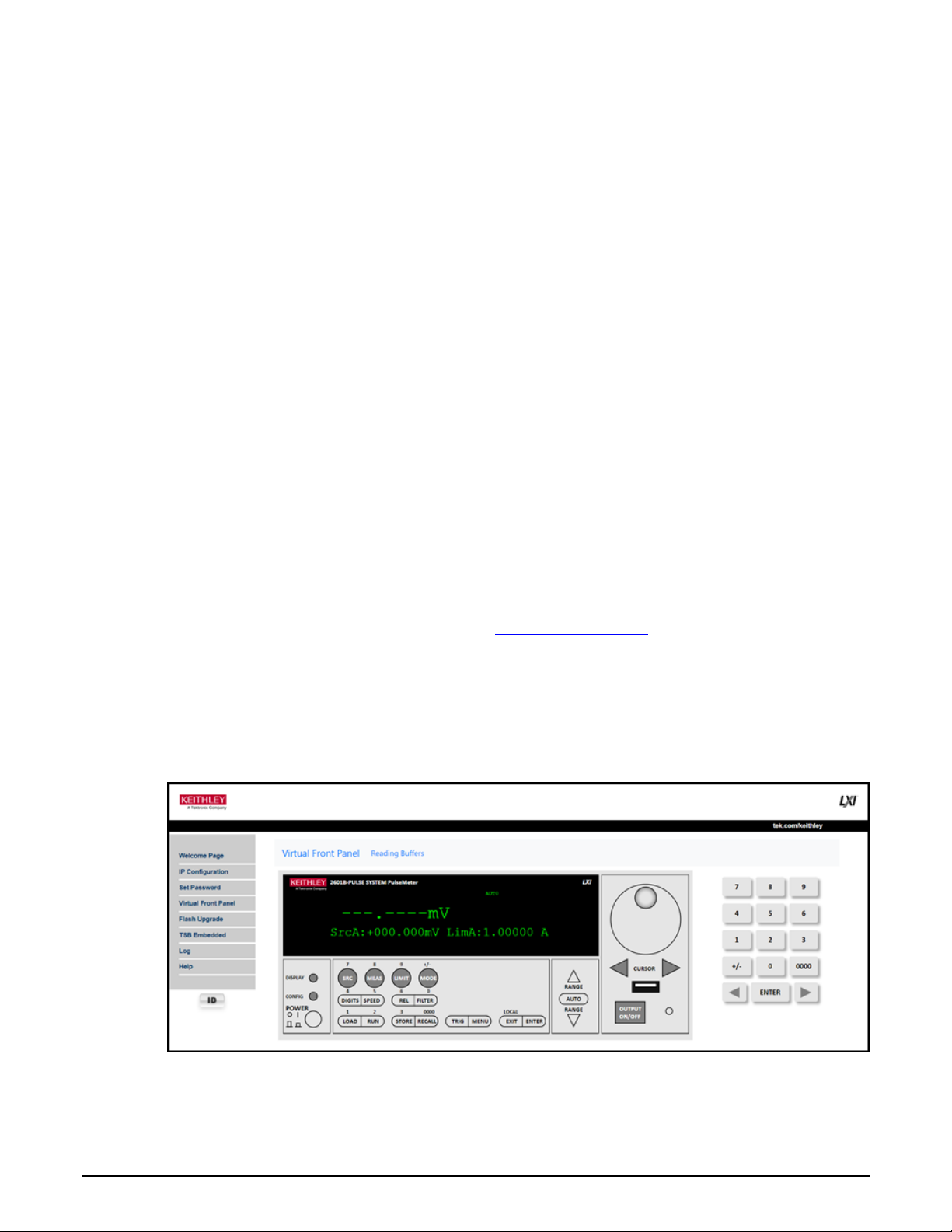
Section 3: Instrument description Model 2601B-PULSE System SourceMeter® Instrument User's Manual
3-32 2601B-PULSE-900-01 Rev. A August 2021
The default password is "" (no password).
You cannot retrieve a lost password from any command interface. You can reset the password from
the front panel. Select MENU, then RESET-PASSWORD.
For information on the TSP commands, refer to localnode.passwordmode in the Model
2601B-PULSE Reference Manual.
To change the password:
1. Select Set Password.
2. In the Current Password box, enter the presently used password.
3. In the New Password and Confirm New Password boxes, enter the new password.
4. Select Submit.
Using the virtual front panel
The Virtual Front Panel page allows you to control the instrument from a computer as if you were
using the front panel of the instrument. You can operate the instrument using a mouse to
select options.
The virtual front panel operates the same way as the actual front panel except that you cannot switch
the instrument on or off with the power switch.
For information on the front-panel controls, see Instrument description (on page 3-1).
To use the virtual front panel, you can use any standard web browsers.
You can access the Virtual Front Panel from multiple interfaces and each interface can make
changes. You may need to refresh the browser to see changes made by another interface.
Figure 37: Virtual front panel
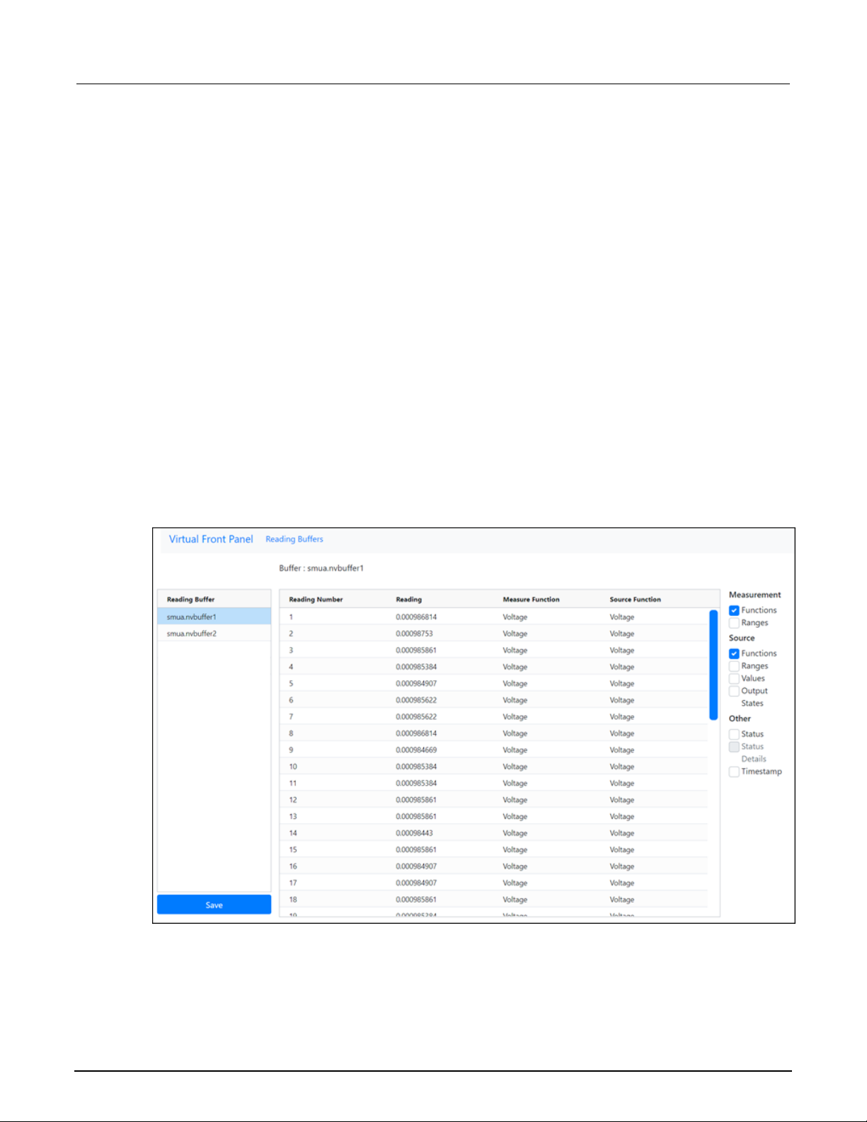
Model 2601B-PULSE System SourceMeter® Instrument User's Manual Section 3: Instrument description
2601B-PULSE-900-01 Rev. A August 2021 3-33
View buffer data using the web interface
You can view the data in the reading buffers on the Reading Buffers page of the Virtual Front Panel
web page.
To view the data, at the top of the virtual front panel, select Reading Buffers. On the Reading Buffers
page, select a reading buffer from the Reading Buffer list. The data is displayed in the table.
Initially, the reading number and reading measurement values are displayed. You can display
additional data using the filters to the right of the table. You can choose:
• Measurement: Include or exclude measurement information.
• Source: Include or exclude source information.
• Other: Include or exclude status, status detail, and timestamp information. For detail on the
Status value, refer to “Buffer status” in the Model 2601B-PULSE Reference Manual.
An example of the Reading Buffers page with the measurement and source functions displayed is
shown in the following figure.
Figure 38: Web interface Reading Buffers page

Section 3: Instrument description Model 2601B-PULSE System SourceMeter® Instrument User's Manual
3-34 2601B-PULSE-900-01 Rev. A August 2021
Download reading buffer data using the web interface
You can download reading buffer data to a .csv file from the Reading Buffers page of the
web interface.
The data shown in the table on the Reading Buffers page is downloaded.
To download buffer data:
1. From the web interface, select Virtual Front Panel.
2. Select Reading Buffers.
3. From the Reading Buffer list, select the reading buffer that contains the data you want
to download.
4. From the options on the right, filter the reading buffer list to display the data you want to
download.
5. Select Save. The file is downloaded to your computer.
6. Follow the instructions for your browser to open the file. Typically, the file opens in
Microsoft Excel.
Using TSB Embedded
TSB Embedded is a script management tool that is available through the web interface of the
instrument. You can use TSB Embedded to create, modify, and save test scripts, and to send
individual commands. TSB Embedded provides some of the features of Test Script Builder (TSB).
TSB is a software tool that simplifies building test scripts for Keithley Instruments that are enabled to
use Test Script Processor (TSP®).
For more information on using TSB Embedded for script management, refer to “Working with TSB
Embedded” in the Model 2601B-PULSE Reference Manual.
Sending individual commands using the web interface
To send individual commands using the web interface:
1. Select TSB Embedded.
2. In the Console box, enter the command.
3. Select Enter to send the command to the instrument. The command is displayed in the Output
box. If there is a response to the command, it is displayed after the command.
4. To clear the Output box, right-click and select Clear.
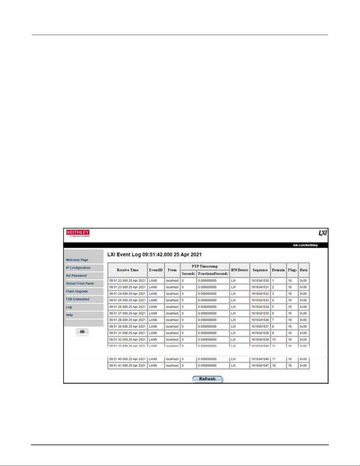
Model 2601B-PULSE System SourceMeter® Instrument User's Manual Section 3: Instrument description
2601B-PULSE-900-01 Rev. A August 2021 3-35
Review events in the LXI Event Log
The Log option opens the LXI Event Log. The event log records all LXI events that the instrument
generates and receives. The log includes the following information:
• The EventID column, which shows the identifier of the event that generated the event message.
• The PTP Timestamp column, which displays the seconds and fractional (nano) seconds when the
event occurred.
• The Data column, which displays the text of the event message.
To clear the event log and update the information on the screen, select Refresh.
Logging LAN trigger events in the event log
You can use the event log to record all LXI triggers generated and received by the 2601B-PULSE.
You can view the event log using any command interface or the embedded web interface. The
following figure shows the view of the LXI event log from the Log option in the embedded
web interface.
Figure 39: LXI Event Log

Section 3: Instrument description Model 2601B-PULSE System SourceMeter® Instrument User's Manual
3-36 2601B-PULSE-900-01 Rev. A August 2021
The timestamp, event identifier, IP address, and the domain name identify the incoming and outgoing
LXI trigger packets. The following table provides detailed descriptions for the columns in the
event log.
Event log descriptions
Column title
Description
Example
Receive Time
Displays the date and time that the LAN trigger
occurred in UTC, 24-hour time
11:46:44.000 11 Mar 2020
Event ID
Identifies the lan.trigger[N] that generates an
event
LAN0 = lan.trigger[1]
LAN1 = lan.trigger[2]
LAN2 = lan.trigger[3]
LAN3 = lan.trigger[4]
LAN4 = lan.trigger[5]
LAN5 = lan.trigger[6]
LAN6 = lan.trigger[7]
LAN7 = lan.trigger[8]
From
Displays the IP address for the device that
generates the LAN trigger
localhost
192.168.5.20
Timestamp
A timestamp that identifies the time the event
occurred; the timestamp uses the following:
▪ PTP timestamp
▪ Seconds
▪ Fractional seconds; the 2601B-PULSE does
not support the IEEE Std 1588 standard; the
values in this field are always 0 (zero)
HWDetect
Identifies a valid LXI trigger packet
LXI
Sequence
Each instrument maintains independent
sequence counters:
▪ One for each combination of UDP multicast
network interface and UDP multicast
destination port
▪ One for each TCP connection
Domain
Displays the LXI domain number; the default value
is 0 (zero)
0
Flags
Contain data about the LXI trigger packet;
values are:
▪ 1 - Error
▪ 2 - Retransmission
▪ 4 - Hardware
▪ 8 - Acknowledgments
▪ 16 - Stateless bit
16
Data
The values for this are always 0 (zero)

Model 2601B-PULSE System SourceMeter® Instrument User's Manual Section 3: Instrument description
2601B-PULSE-900-01 Rev. A August 2021 3-37
Accessing the event log from the command interface
You can access the event log from any remote command interface. The event log must be enabled
before LXI trigger events can be viewed. To enable the event log, send:
eventlog.enable = 1
To view the event log from a remote interface, send:
print(eventlog.all())
This command outputs one or more strings similar to the following:
14:14:02.000 17 Jun 2019, LAN0, 10.80.64.191, LXI, 0, 1560780842, not available, 0,
0x10,0x00
The string displays the same information as the web interface. Commas separate the fields. The
fields output in the following order:
• Received time (UTC time)
• Event ID
• From (Sender)
• HWDetect / version
• Domain
• Sequence number
• Timestamp (PTP time)
• Epoch (from 1588)
• Flags
• Data
See the table in Logging LAN trigger events in the event log (on page 3-35) for detailed descriptions.
To generate log traffic, send the code:
local id = 1
lan.trigger[id].ipaddress = lan.status.ipaddress
lan.trigger[id].connect()
for domain = 1, 255 do
print(domain)
lan.lxidomain = domain
lan.trigger[id].assert()
delay(1)
end
Help
The help page in the web interface provides basic help for the web interface, a glossary of terms, and
a link to licenses for the virtual front panel, firmware upgrade tool, and TSB Embedded.

In this section:
Operation overview .................................................................. 4-1
DUT test connections ............................................................... 4-7
Sense mode selection ............................................................ 4-20
Output-off modes ................................................................... 4-21
Pulser operation ..................................................................... 4-25
Using the trigger model .......................................................... 4-32
Operation overview
The 2601B-PULSE is a single channel source-measure instrument with the full SMU functionality of a
Model 2601B SourceMeter® Instrument plus a high-speed current pulser.
The instrument operates as a SMU or as a current pulser. Internally, a solid-state switch routes the
SMU or pulser to the output terminals, as shown in the following figure.
Figure 40: SMU and pulser operation
Section 4
Operation

Section 4: Operation Model 2601B-PULSE System SourceMeter® Instrument User's Manual
4-2 2601B-PULSE-900-01 Rev. A August 2021
When the pulser is disabled, the instrument provides the full functionality of a 4-quadrant SMU. You
can use the front panel or remote commands to configure the instrument to perform the following
source-measure operations:
• Source voltage: Measure and display current, voltage, resistance, or power
• Source current: Measure and display voltage, current, resistance, or power
• Measure resistance: Display resistance calculated from voltage and current components of
measurement (can optionally specify source voltage or source current value)
• Measure power: Display power calculated from voltage and current components of
measurement (can optionally specify source voltage or source current value)
• Measure only (V or I): Display voltage or current measurement
When the pulser is enabled, the instrument generates fast-edge current pulses only. It measures
current, voltage, resistance, or power. The pulser sourcing and measuring functionality is only
available using remote commands. Pulser protection levels and some measurements are displayed
on the front-panel interface.
Limits
Limits are only applied when the pulser is disabled. When the pulser is enabled, protection levels
are applied.
When sourcing voltage, you can set the instrument to limit current or power. Conversely, when
sourcing current, you can set the instrument to limit voltage or power. In steady-state conditions, the
instrument output does not exceed the limit. The maximum limit is the same as the maximum values
listed in the following table.
The limit circuit limits in either polarity regardless of the polarity of the source or limit value. The
accuracy of the limit opposite in polarity from the source is diminished unless the instrument is in sink
mode (on page 4-5). The maximum limits are based on source range.
The limit operation of the instrument changes dependent on the source mode (current or voltage),
load, and the configured limits (current, voltage, and power). It is important to distinguish both the
current and voltage limits from the power limit. As the names imply, the current limit restricts the
current for sourced voltage, and the voltage limit restricts the voltage for a sourced current. The
power limit, however, restricts power by lowering the present limit in effect (voltage or current) as
needed to restrict the SMU from exceeding the specified power limit. For additional details on using
limits, including load considerations when specifying both a current (or a voltage) limit and a power
limit, see “Operating boundaries” in the Model 2601B-PULSE Reference Manual.
For additional information on limits, refer to:
• Pulser operation (on page 4-25)
• “Limit principles” in the Model 2601B-PULSE Reference Manual

Model 2601B-PULSE System SourceMeter® Instrument User's Manual Section 4: Operation
2601B-PULSE-900-01 Rev. A August 2021 4-3
The only exception to the limit not being exceeded is the voltage limit when operating as a current
source. To avoid excessive (and potentially destructive) currents from flowing, the voltage limit
sources or sinks up to 102 mA for current source ranges on or below 100 mA. For the ranges 1 A
and above, the maximum current allowed is the current source setting.
Source range
Maximum limit
100 mV
1 V
6 V
40 V
3 A
3 A
3 A
1 A
100 nA
1 µA
10 µA
100 µA
1 mA
10 mA
100 mA
1 A
3 A
40 V
40 V
40 V
40 V
40 V
40 V
40 V
40 V
6 V
Setting the limit
Set the limit from the front panel as follows:
1. Press the LIMIT key to directly access limit editing. Pressing the LIMIT key while in limit edit
mode toggles the display between the complementary function limit and the power limit display.
2. Press the navigation wheel and set the limit to the new value.
3. Press the ENTER key or the navigation wheel to complete editing.
4. Press the EXIT (LOCAL) key to return to the main display.
Set the limit using remote commands as follows:
The table below summarizes basic commands to program a limit. For a more complete description of
these commands, refer to the “TSP command reference” section of the Model 2601B-PULSE
Reference Manual.
Limit commands
Command
Description
smua.source.limiti = limit
Set current limit.
smua.source.limitv = limit
Set voltage limit.
smua.source.limitp = limit
Set power limit.
compliance = smua.source.compliance
Test if in limit (true = in limit; false = not in limit).

Section 4: Operation Model 2601B-PULSE System SourceMeter® Instrument User's Manual
4-4 2601B-PULSE-900-01 Rev. A August 2021
To set the limit, send the command with the limit value as the parameter. The following programming
example illustrates how to set the current, voltage, and power limit to 50 mA, 4 V, and 1 W
respectively:
smua.source.limiti = 50e-3
smua.source.limitv = 4
smua.source.limitp = 1
The following programming example illustrates how to print the limit state:
print(smua.source.compliance)
A returned value of true indicates one of the following things:
• If the instrument is configured as a current source, the voltage limit has been reached
• If the instrument is configured as a voltage source, the current limit has been reached
Pulser protection circuit
The pulser has two protection circuits, one for the sense terminals and one for the force terminals.
Both are set using remote commands. When either of the protection circuits are exceeded, the
instrument generates the 5127 "Output protection level exceeded" error and the current pulse
terminates within 3 µs.
The sense terminals are monitored by the voltage protection circuit. If the voltage on the sense
terminals goes above the protection level, the output is turned off. If the level was exceeded during a
sweep, the output is shorted until all trigger counts are satisfied, then the output is turned off. The
voltage protection level can be set from 5 percent to 200 percent of the pulser voltage range.
The force terminals are monitored by the absolute voltage protection circuit. If the voltage on the force
terminals goes above the protection level, the 2601B-PULSE automatically turns off the output. The
absolute voltage level can be set from 2 V to 40 V, independent of the range. This level ignores
normal transients during pulse rise and fall times.
For information on the commands for the pulser protection circuit, refer to the following command
descriptions in the Model 2601B-PULSE Reference Manual:
• smua.pulser.protect.sensev
• smua.pulser.protect.sourcev
Setting a protection level does not guarantee that the output will not go above the protection
level. The 2601B-PULSE turns off the output as quickly as possible, but the voltage level can
briefly exceed this level, potentially causing damage to the device under test (DUT).

Model 2601B-PULSE System SourceMeter® Instrument User's Manual Section 4: Operation
2601B-PULSE-900-01 Rev. A August 2021 4-5
Setting and checking the pulser protection levels
To set the voltage protection level using remote commands:
Send the command smua.pulser.protect.sensev with the level defined. For example, to set a
protection level of 8 V, send:
smua.pulser.protect.sensev = 8
To set the absolute voltage protection level using remote commands:
Send the command smua.pulser.protect.sourcev with the level defined. For example, to set
an absolute voltage level of 24 V, send:
smua.pulser.protect.sourcev = 24
To determine if a pulser level protection was tripped, send:
print(smua.pulser.protect.tripped)
A returned value of true indicates that the protection circuit was tripped. The following events can
trip the protection circuit:
• A voltage greater than smua.pulser.protect.sensev was detected on the sense terminals.
• A voltage greater than smua.pulser.protect.sourcev was detected on the force terminals.
• The maximum pulse width was exceeded during trigger model operation.
• The maximum duty cycle was exceeded during trigger model operation.
• If the SMU cannot keep up with the pulse rate.
• If the SMU cannot keep up with the measurement rate.
The status is reset to false when the pulser is disabled or when the output is turned on.
Sink operation
Carefully consider and configure the appropriate output-off state, source function, and
compliance limits before connecting the 2601B-PULSE to a device that can deliver energy (for
example, other voltage sources, batteries, capacitors, solar cells, or other 2601B-PULSE
instruments). Configure recommended instrument settings before making connections to the
device. Failure to consider the output-off state, source, and compliance limits may result in
damage to the instrument or to the device under test (DUT).
When the instrument is operating as a sink, voltage and current have the opposite polarity. During
sink operation, the instrument dissipates power instead of sourcing it. An external source, such as a
battery, or an energy storage device, such as a capacitor, can force operation into the sink region.

Section 4: Operation Model 2601B-PULSE System SourceMeter® Instrument User's Manual
4-6 2601B-PULSE-900-01 Rev. A August 2021
When the pulser is disabled, the accuracy of the limit opposite in polarity from the source is
diminished unless the instrument is in sink mode. Enabling sink mode reduces the source limit
inaccuracy seen when operating in quadrants II and IV. Quadrants I and III show this source limit
inaccuracy.
For example, if a 12 V battery is connected to the voltage source (HI to battery +) that is programmed
for +10 V, sink operation occurs in the second quadrant (source +V and measure −I).
When using the SMU current source as a sink, always set the voltage compliance to a level
that is higher than the external voltage level. Failure to do so could result in excessive
current flow into the instrument and incorrect measurements. See Limits (on page 4-2) for
details about compliance limits.
The sink operating limits are shown in “Continuous power operating boundaries” in the
Model 2601B-PULSE Reference Manual.
Setting the sink mode using the front panel
To enable or disable the sink mode from the front panel:
1. Press the CONFIG key and then the SRC key.
2. Select V-SOURCE.
3. Select SINK-MODE.
4. Select ENABLE or DISABLE.
5. Press the ENTER key. Sink mode is enabled or disabled, as applicable.
6. Press the EXIT (LOCAL) key twice to return to the main display.
Setting the sink mode from a remote interface
To enable sink mode from the remote interface, send:
smua.source.sink = smua.ENABLE
To disable sink mode, send:
smua.source.sink = smua.DISABLE
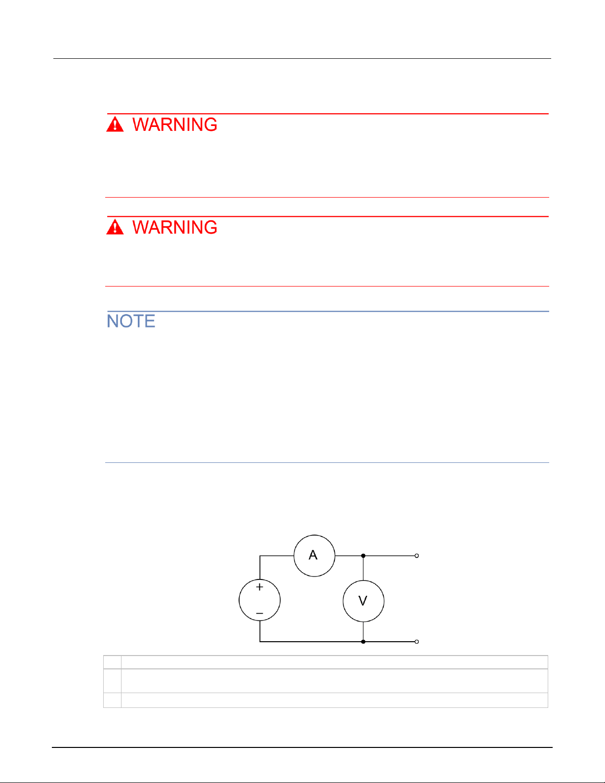
Model 2601B-PULSE System SourceMeter® Instrument User's Manual Section 4: Operation
2601B-PULSE-900-01 Rev. A August 2021 4-7
DUT test connections
Hazardous voltages may be present in the test system. To prevent injury or death, remove
power from the instrument or test system and discharge any energy storage components (for
example, capacitors or cables) before changing any connections that might allow contact
with an uninsulated conductor.
SENSE LO and FORCE LO are not internally connected to the chassis. Do not allow them to
float above 0 V. Failure to adhere to these guidelines can result in personal injury or death
due to electric shock.
On some sensitive or easily damaged devices under test (DUTs), the instrument power-up and
power-down sequence can apply transient signals to the DUT that may affect or damage it. When
testing this type of DUT, do not make final connections to it until the instrument has completed its
power-up sequence and is in a known operating state. When testing this type of DUT, disconnect it
from the instrument before turning the instrument off.
To prevent any human contact with a live conductor, connections to the DUT must be fully insulated
and the final connections to the DUT must only use safety-rated safety-jack-socket connectors that
do not allow bodily contact.
The fundamental source-measure configurations for the 2601B-PULSE are shown in the following
figures. When sourcing voltage, you can measure current or voltage, as shown in the following figure.
Figure 41: Fundamental source-measure configurations: Source V
A
Current meter
+ − Voltage source
V
Voltage meter

Section 4: Operation Model 2601B-PULSE System SourceMeter® Instrument User's Manual
4-8 2601B-PULSE-900-01 Rev. A August 2021
When the SMU or pulser is sourcing current, you can measure voltage or current, as shown in the
following figure.
Figure 42: Fundamental source-measure configuration: Source I
A
Current meter
↑
Current source
V
Voltage meter
See “Basic circuit configurations” in the Model 2601B-PULSE Reference Manual for
detailed information.
FORCE and SENSE connectors
You make connections from the instrument to the device under test (DUT) using the BNC connections
on the 2601B-P-INT.
The FORCE HI, FORCE LO, and SENSE HI connectors of the 2601B-P-INT have GUARD on the
shell. The SENSE LO connector has FORCE LO on the shell.
Figure 43: 2601B-P-INT FORCE and SENSE shell connections
The FORCE LO shell connection is for shielding only and should not be used to carry signal. Use the
center pin of the FORCE LO connector to carry signal.

Model 2601B-PULSE System SourceMeter® Instrument User's Manual Section 4: Operation
2601B-PULSE-900-01 Rev. A August 2021 4-9
Figure 44: Coaxial connectors for 2601B-PULSE
All connections are electrically isolated from chassis ground.
The rear panel of the 2601B-PULSE provides a low-noise chassis ground banana jack that can be
used as a common signal ground point for the SENSE and FORCE LOs. This low-noise signal ground
banana jack is connected to the chassis through a frequency variable resistor (FVR). The FVR,
shown in the figure below, is used to isolate the SMU from high frequencies that may be present on
the chassis of the 2601B-PULSE. As frequencies on the chassis increase, the resistance of the FVR
increases to dampen their effects. For dc to 60 Hz, the FVR is a virtual short (zero Ω).
The chassis screw terminal is connected to the metal chassis of the 2601B-PULSE.
Figure 45: Chassis ground banana jack
1 Low-noise chassis ground banana jack
2 Signal ground
3 Frequency variable resistor (FVR)
4 Chassis
5 Chassis screw
Do not use the chassis as a ground point for signal connections. High frequencies on the chassis of
the 2601B-PULSE may result in higher noise. The chassis should only be used as a safety shield.
Use the chassis screw for connections to the chassis of the 2601B-PULSE.

Section 4: Operation Model 2601B-PULSE System SourceMeter® Instrument User's Manual
4-10 2601B-PULSE-900-01 Rev. A August 2021
The FORCE and SENSE connectors of the 2601B-PULSE are rated for connection to circuits
rated Measurement Category I only, with transients rated less than 1500 V
PEAK
. Do not
connect the 2601B-PULSE terminals to CAT II, CAT III, or CAT IV circuits. Connections of the
input/output connectors to circuits higher than CAT I can cause damage to the equipment or
expose the operator to hazardous voltages.
To prevent electric shock and/or damage to the 2601B-PULSE, when connecting to a source
with a greater current capability than the 2601B-PULSE, a user-supplied fuse, rated at no
more than 20 A SLO-BLO, should be installed in-line with the 2601B-PULSE
input/output connectors.
2-wire local sensing connections
Local voltage sensing is only available when the pulser is disabled.
You can use 2-wire local sensing measurements, shown in the following figure, for the following
source-measure conditions:
• Sourcing and measuring current.
• Sourcing and measuring voltage in high impedance (more than 1 kΩ) test circuits.
Make sure to configure the 2601B-PULSE for 2-wire local sensing. Refer to Sense mode selection
(on page 4-20) for information.
Figure 46: Two-wire local sensing 2601B-P-INT connections
4-wire remote sensing connections
When sourcing or measuring voltage in a low-impedance test circuit, there can be errors associated
with lead resistance. Voltage source and measure accuracy is optimized by using 4-wire remote
sense connections. When sourcing voltage, 4-wire remote sensing ensures that the programmed
voltage is delivered to the DUT. When measuring or limiting voltage, only the voltage drop across the
DUT is measured.
 Loading...