

Page 1

Keithley Instruments
28775 Aurora Road
Cleveland, Ohio 44139
1-800-935-5595
tek.com/keithley
2601B-PULSE System SourceMeter Instrument
071374500 April 2020
*P071374500*
1
Category
Specification
Power supply
100 V ac to 240 V ac, 50 Hz or 60 Hz (autosensing). 240 VA maximum
Input and output connections
See Front panel (on page 3) and Rear panel (on page 6)
Environmental conditions
For indoor use only.
Operating altitude: Maximum 2000 meters (6562 feet) above sea level
Operating temperature: 0 °C to 35 °C at up to 70% relative humidity; at
35 °C to 50 °C, derate 3% relative humidity per °C
Storage: −25 °C to 65 °C
Pollution degree: 1 or 2
Source input electrical ratings
Voltage
40 V dc maximum
Current
3 A maximum at 6 V dc, 1 A maximum at 40 V dc
Pulser feature output, region 4
Region maximums
10 A at 20 V
Maximum pulse width
1.8 ms
Maximum duty cycle
1%
Measure input electrical ratings
Measurement category
O
Voltage
40 V dc maximum HI to LO
Current
3 A maximum at 6 V dc, 1 A maximum at 40 V dc
Impedance
Variable
Safety Supplement
Introduction
This supplement provides you with basic installation, front panel, and rear panel information to help you start
using your Keithley Instruments 2601B-PULSE instrument safely.
For detailed information about these topics, refer to the Model 2601B-PULSE Reference Manual, available from
the Keithley Instruments website (tek.com/keithley).
Power and environmental ratings
The 2601B-PULSE power and environmental ratings and connections are listed in the following tables.
Page 2

2601B-PULSE System SourceMeter Instrument Safety Supplement
2 071374500 April 2020
Supply connection and grounding requirements
Before operating an instrument, make sure that the line cord is connected to a properly grounded, appropriately
rated power receptacle. Inspect the connecting cables, test leads, and jumpers for possible wear, cracks, or
breaks before each use.
When installing equipment where access to the main power cord is restricted, such as rack mounting, a
separate main input power disconnect device must be provided in close proximity to the equipment and within
easy reach of the operator.
Assembly, location, and mounting requirements
The 2601B-PULSE can be mounted in a standard 19-inch rack (horizontal mountings only; mounting vertically
may impede the cooling mechanisms).
When rack mounting the 2601B-PULSE, make sure there is adequate airflow around at least one side to
ensure proper cooling. Adequate airflow enables air temperatures within approximately one inch of the
2601B-PULSE surfaces to remain within specified limits under all operating conditions. The cooling
specifications state:
▪ Forced air
▪ Side intake, rear exhaust
▪ One side must be unobstructed when rack mounted
Ventilation requirements
To prevent damaging heat build-up and ensure specified performance, observe the following precautions.
The rear exhaust vent and at least one side vent must be kept free of any obstructions. Even partial blockage
could impair proper cooling.
▪ Do not position any devices adjacent to the 2601B-PULSE that force air (heated or unheated) into or onto
its cooling vents or surfaces. This additional airflow could compromise accuracy performance.
▪ When rack mounting the 2601B-PULSE, make sure there is adequate airflow around at least one side to
ensure proper cooling. Adequate airflow enables air temperatures within approximately one inch of the
2601B-PULSE surfaces to remain within specified limits under all operating conditions.
▪ Do not rack-mount high power-dissipation equipment adjacent to the 2601B-PULSE that could cause
excessive heating to occur. The specified ambient temperature must be maintained around the surfaces of
the 2601B-PULSE to maintain specified accuracies.
Page 3

2601B-PULSE System SourceMeter Instrument Safety Supplement
071374500 April 2020 3
Power switch. The in position turns the 2601B-PULSE on (I); the out position turns it
off (O).
Toggles between the various source-measure displays and the user message mode.
Configures a function or operation.
SMU (source-measure unit) setup
SRC
Selects the source function (voltage or current) and places the cursor in the source field
for editing.
MEAS
Cycles through measure functions (V, A, Ω or W).
LIMIT
Places the cursor in the compliance limit field for editing. Also selects the limit value to
edit (V, A, or W).
MODE
Selects a meter mode (I-METER, V-METER, OHM-METER, or WATT-METER).
Front panel
The front panel of the 2601B-PULSE is shown below. The descriptions of the front-panel controls, USB port,
and indicators follow the figure.
Figure 1: 2601B-PULSE front-panel controls
1. Power switch, display and configuration keys
2. SMU setup, performance control, special operation, and numbers
Page 4

2601B-PULSE System SourceMeter Instrument Safety Supplement
4 071374500 April 2020
Performance control
DIGITS
SPEED
REL
FILTER
Special operation
LOAD
Loads test for execution (FACTORY, USER, or SCRIPTS).
RUN
Runs the last selected factory or user-defined test.
STORE
Accesses reading buffers and takes readings. TAKE_READINGS: Use to take readings
and store them in a reading buffer. SAVE: Use to save a reading buffer to nonvolatile
memory or to a user-installed flash drive (USB1) in CSV or XML format. Readings
include measurements, source values, and timestamp values, if configured.
RECALL
Recalls information (DATA or STATISTICS) stored in a reading buffer: DATA includes
stored readings, and if configured, source values and timestamp values; STATISTICS
includes MEAN, STD DEV, SAMPLE SIZE, MINIMUM, MAXIMUM, PK-PK.
TRIG
Triggers readings.
MENU
Accesses the main menu. The main menu can be used to configure many functions
and features.
EXIT
Cancels the selection and returns to the previous menu or display. Also used as a
LOCAL key to take the instrument out of remote operation.
ENTER
Accepts the selection and moves to the next choice or exits the menu.
Numbers
Number keys
Sets the display resolution (4½, 5½, or 6½ digits).
Sets the measurement speed (FAST, MEDium, NORMAL, HI-ACCURACY, or
OTHER). Speed and accuracy are set by controlling the measurement aperture.
Controls relative measurements, which allows a baseline value to be subtracted from a
reading.
Enables or disables the digital filter. You can use this filter to reduce reading noise.
When enabled and in EDIT mode, the number keys (0-9, +/-, 0000) allow direct numeric
entry. Press the navigation wheel to enter EDIT mode.
Page 5

2601B-PULSE System SourceMeter Instrument Safety Supplement
071374500 April 2020 5
3. Range keys
Selects the next higher source or measure range.
Enables or disables source or measure autorange.
Selects the next lower source or measure range.
In addition to selecting range functions, the up and down range keys change the format
for non-range numbers (as an example, when editing the limit value).
4. Output control
Turns the source output on or off.
5. USB port
Use the USB port to connect a USB flash drive to the instrument. You can use the USB
flash drive to store reading buffer data, scripts, and user setups. You can also use it to
upgrade the firmware.
6. Cursor keys
Use the CURSOR keys to move the cursor left or right. When the cursor is on the
source or compliance value digit, press the navigation wheel to enter edit mode, and
turn the navigation wheel to edit the value. Press the navigation wheel again when you
finish editing.
Use the CURSOR keys or the navigation wheel to move through menu items. To view a
menu value, use the CURSOR keys for cursor control, and then press the navigation
wheel to view the value or sub-menu item.
7. Navigation wheel
Turn the navigation wheel to:
▪ Move the cursor to the left and the right (the cursor indicates the selected value
or item)
▪ While in edit mode, increase or decrease a selected source or compliance value
Push the navigation wheel to:
▪ Enable or disable edit mode for the selected source or compliance value
▪ Open menus and submenu items
▪ Select a menu option or a value
Page 6

2601B-PULSE System SourceMeter Instrument Safety Supplement
6 071374500 April 2020
8. Display indicators (not shown)
The items listed below represent the possible display indicators and their meanings.
Indicator
Meaning
4W
Remote (4-wire) sense selected
AUTO
Source or measure autorange is selected
EDIT
Instrument is in editing mode
ERR
Questionable reading or invalid calibration step
FILT
Digital filter is enabled
LSTN
Instrument is addressed to listen
REL
Relative mode is enabled
REM
Instrument is in remote mode
SRQ
Service request is asserted
TALK
Instrument is addressed to talk
* (asterisk)
Readings are being stored in the buffer
Rear panel
The rear panel of the 2601B-PULSE is shown below. The descriptions of the rear-panel components follow
the figure.
Figure 2: Rear panel
Page 7

2601B-PULSE System SourceMeter Instrument Safety Supplement
071374500 April 2020 7
1. FORCE HI and FORCE LO connectors
These connectors provide connections for FORCE HI and FORCE LO.
2. SENSE LO and SENSE HI connectors
These connectors provide connections for SENSE LO and SENSE HI.
3. STATUS indicator
This LED indicates the status of the interlock. When the interlock is not
asserted, the indicator is off. When the interlock is asserted, the indicator
is on.
4. INTERLOCK connector
This connector provides a connection for the optional interlock. Refer to
"Using the interlock" in the Model 2601B-PULSE Reference Manual for
information on setting up and connecting the interlock.
5. Digital I/O
Female DB-25 connector. Use a cable equipped with a male DB-25
connector (Keithley Instruments part number CA-126-1).
Pins provided:
▪ Fourteen digital input or output pins
▪ Seven GND pins
▪ Three +5 V pins
6. IEEE-488
Connector for IEEE-488 (GPIB) operation. Use a shielded cable, such as
the Keithley Instruments Model 7007-1 or Model 7007-2.
7. Cooling exhaust vents
Exhaust vent for the internal cooling fan. Keep the vent free of obstructions
to prevent overheating. Also see Cooling vents (on page 8).
Page 8
2601B-PULSE System SourceMeter Instrument Safety Supplement
8 071374500 April 2020
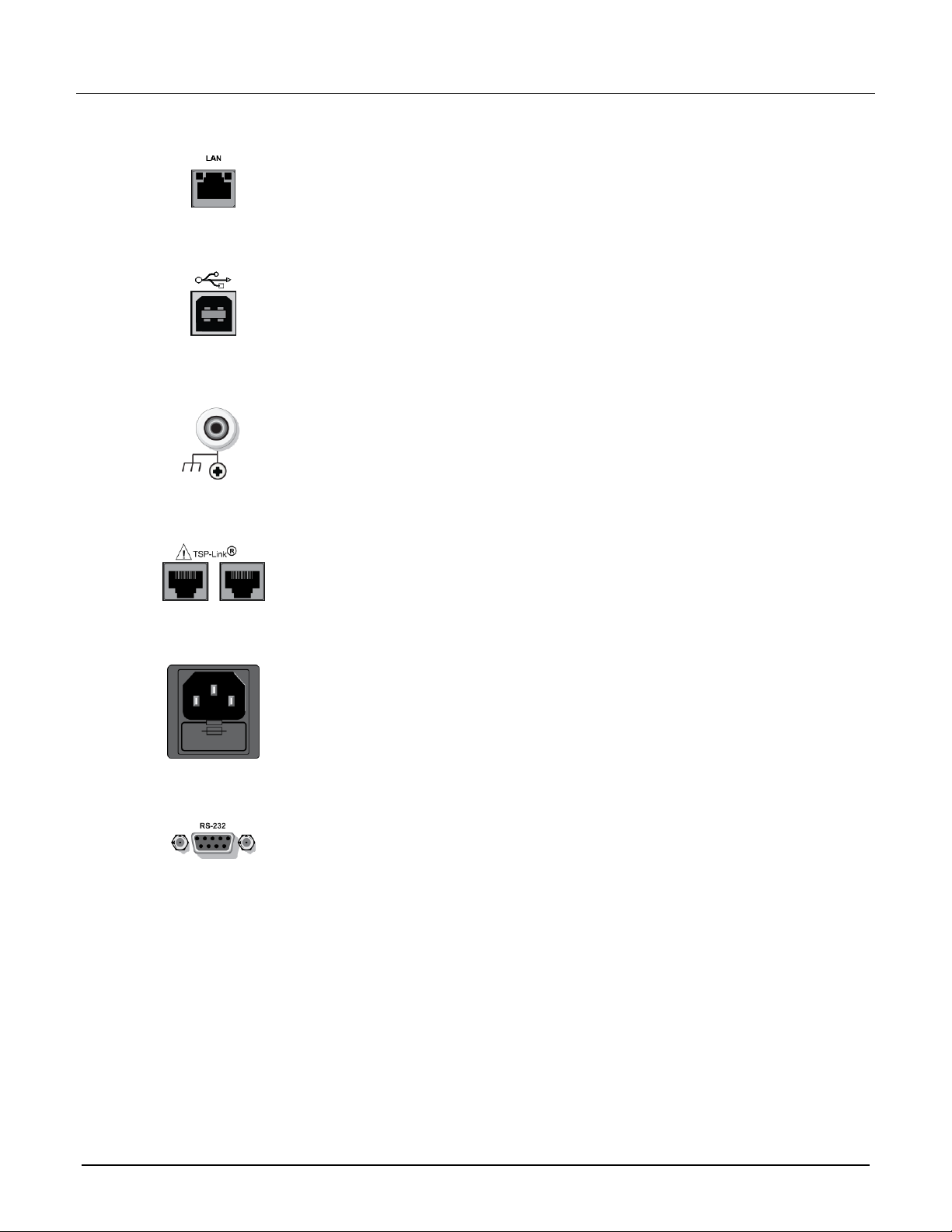
RJ-45 connector for a local area network (LAN). The LAN interface
supports Auto-MDIX, so either a CAT-5e crossover cable (provided), or a
normal CAT-5e straight-through cable (not provided) can be used.
This USB-2.0 receptacle (Type B) located on the rear panel is used to
connect the instrument to a computer. You can use this connection to send
commands to the instrument.
Ground terminal for connection output HI or LO to chassis ground.
Ground screw for connections to chassis ground.
Expansion interface that allows a 2601B-PULSE and other TSP-enabled
instruments to trigger and communicate with each other. Use a category 5e
or higher LAN crossover cable.
Contains the AC line receptacle and power line fuse. The instrument can
operate on line voltages of 100 V to 240 VAC at line frequencies of 50 Hz
or 60 Hz.
Female DB-9 connector. For RS-232 operation, use a straight-through (not
null modem) DB-9 shielded cable (Keithley Instruments Model 7009-5) for
connection to the computer.
8. LAN
9. USB port
10. Ground
11. TSP-Link
12. Power module
13. RS-232
Cooling vents
The 2601B-PULSE has side and top intake and rear exhaust vents. One side must be unobstructed to
dissipate heat.
Excessive heat could damage the 2601B-PULSE and degrade its performance. Only operate the
2601B-PULSE in an environment where the ambient temperature does not exceed 50 °C.
Do not place a container of liquid (water or coffee, for instance) on the top cover. If it spills, the liquid may enter
the case through the vents and cause severe damage.
Page 9

2601B-PULSE System SourceMeter Instrument Safety Supplement
071374500 April 2020 9
To prevent damaging heat build-up and ensure specified performance, use the
following guidelines.
The rear exhaust vent and either the top or both side intake vents must be unobstructed to
properly dissipate heat. Even partial blockage could impair proper cooling.
Do not position any devices adjacent to the 2601B-PULSE that force air (heated or unheated)
toward its cooling vents or surfaces. This additional airflow could compromise accuracy.
When rack mounting the 2601B-PULSE, make sure there is adequate airflow around both
sides to ensure proper cooling. Adequate airflow enables air temperatures within
approximately one inch of the 2601B-PULSE surfaces to remain within specified limits under
all operating conditions.
If you rack mount high power-dissipation equipment next to the 2601B-PULSE, it could cause
excessive heating. To produce specified 2601B-PULSE accuracies, maintain the specified
ambient temperature around the surfaces of the 2601B-PULSE. In rack configurations with
convection cooling only, proper cooling practice places the hottest non-precision equipment
(for example, the power supply) at the top of the rack away from and above precision
equipment (such as the 2601B-PULSE).
Mount precision equipment as low as possible in the rack, where temperatures are coolest.
Adding space panels above and below the 2601B-PULSE will help provide adequate airflow.
Starting up your instrument
The following topics describe how to power your instrument on and off, place the instrument in standby,
configure the line frequency, and replace the line fuse.
Turning the instrument on and off
The 2601B-PULSE operates from a line voltage of 100 V to 240 V at a frequency of 50 Hz or 60 Hz. Line
voltage is automatically sensed (there are no switches to set). Make sure the operating voltage in your area
is compatible.
Follow the procedure below to connect the 2601B-PULSE to line power and turn on the instrument.
Page 10
2601B-PULSE System SourceMeter Instrument Safety Supplement
10 071374500 April 2020
Operating the instrument on an incorrect line voltage may cause damage to the instrument,
possibly voiding the warranty.
To turn a 2601B-PULSE on and off:
1. Before plugging in the power cord, make sure that the front panel POWER switch is in the off (O) position.
2. Connect the female end of the supplied power cord to the AC receptacle on the rear panel.
3. Connect the other end of the power cord to a grounded AC outlet.
The power cord supplied with the 2601B-PULSE contains a separate protective earth (safety
ground) wire for use with grounded outlets. When proper connections are made, the
instrument chassis is connected to power-line ground through the ground wire in the power
cord. In addition, a chassis ground connection is provided through a screw on the rear panel.
This terminal should be connected to a known protective earth. In the event of a failure, not
using a properly grounded protective earth and grounded outlet may result in personal injury
or death due to electric shock.
Do not replace detachable mains supply cords with inadequately rated cords. Failure to use
properly rated cords may result in personal injury or death due to electric shock.
Hazardous voltages may be present on all measurement terminals. To prevent electrical
shock that could cause injury or death, remove power from the instrument or test system and
discharge any energy storage components (for example, capacitors or cables) before
changing any connections that might allow contact with an uninsulated conductor.
On some sensitive or easily damaged devices under test (DUTs), the instrument power-up and
power-down sequence can apply transient signals to the DUT that may affect or damage it. When
testing this type of DUT, do not make final connections to it until the instrument has completed its
power-up sequence and is in a known operating state. When testing this type of DUT, disconnect it
from the instrument before turning the instrument off.
To prevent any human contact with a live conductor, connections to the DUT must be fully insulated
and the final connections to the DUT must only use safety-rated safety jack socket connectors that
do not allow bodily contact.
4. To turn your instrument on, press the front panel POWER switch to place it in the on (I) position.
5. To turn your instrument off, press the front panel POWER switch to place it in the off (O) position.
Page 11

2601B-PULSE System SourceMeter Instrument Safety Supplement
071374500 April 2020 11
Placing a 2601B-PULSE in standby
Placing the 2601B-PULSE in standby does not place the instrument in a safe state (an
interlock is provided for this function).
When the instrument is on, the output may be placed in an active output state (output on) or a standby mode
(output off). From the front panel, pressing the OUTPUT ON/OFF control toggles the output using the present
instrument configuration. You can also place the output in standby over the remote interface by sending the
following command:
smua.source.output = smua.OUTPUT_OFF
Even though the instrument is placed in standby, the output may not be actually off.
Warmup period
The 2601B-PULSE must be turned on and allowed to warm up for at least two hours to achieve
rated accuracies.
Line frequency configuration
The factory configures the 2601B-PULSE to automatically detect the power line frequency (either 50 Hz or
60 Hz) at each power-up. This detected line frequency is used for aperture (NPLC) calculations.
In noisy environments, you can manually configure the instrument to match the actual line frequency.
To configure the line frequency from the front panel:
1. Press the MENU key, then turn the navigation wheel to select LINE-FREQ, and then press the
ENTER key.
2. Turn the navigation wheel to select the appropriate frequency and then press the ENTER key. To
configure the instrument to automatically detect line frequency at each power-up, select AUTO.
3. Press the EXIT (LOCAL) key to return to the main display.
To configure the line frequency from a remote interface:
Set the localnode.linefreq or the localnode.autolinefreq attribute. To set the line frequency to
60 Hz, send:
localnode.linefreq = 60
To configure the instrument to automatically detect line frequency at each power-up:
localnode.autolinefreq = true
Page 12

2601B-PULSE System SourceMeter Instrument Safety Supplement
12 071374500 April 2020
Line fuse replacement
A fuse on the 2601B-PULSE rear panel protects the power line input of the instrument. Follow the below
instructions to replace the fuse. You do not need to return your instrument for service if the fuse is damaged.
Disconnect the line cord at the rear panel and remove all test leads connected to the
instrument before replacing a line fuse. Failure to do so could expose the operator to
hazardous voltages that could result in personal injury or death.
Figure 3: Fuse replacement
To prevent injury, death, or instrument damage, use only the correct fuse type (see table).
To replace the line fuse:
1. Power off the instrument and remove the line cord.
2. The fuse drawer (item 1 in the figure) is located below the AC receptacle. A small tab is on the top of the
fuse drawer (item 2). Use a thin-bladed knife or a screwdriver to pry this tab away from the AC receptacle.
3. Slide the fuse drawer out to gain access to the fuse (the fuse drawer does not pull completely out of the
power module).
4. Snap the fuse out of the drawer and replace it with the same type (the fuse is specified in the table below).
5. Push the fuse drawer back into the module.
If a fuse continues to become damaged, a circuit malfunction exists and must be corrected. Return the
instrument to Keithley Instruments for repair.
Line fuse
Line voltage
Rating
Keithley part number
100 V to 240 V
250 V, 3.15 A, slow blow 5 x 20 mm
FU-106-3.15
Page 13

2601B-PULSE System SourceMeter Instrument Safety Supplement
071374500 April 2020 13
System information
You can display serial number, firmware revision, and calibration dates through the front panel by selecting
SYSTEM-INFO from the main menu.
To view the system information from the front panel:
1. Press the MENU key.
2. Select SYSTEM-INFO.
3. Select one of the following:
▪ FIRMWARE
▪ SERIAL#
▪ CAL
For remote programming, use the *IDN? query to read system information.
Beeper
The 2601B-PULSE includes a beeper. When it is enabled, a beep indicates one of the following actions have
occurred:
▪ A front-panel key was pressed: A short beep, similar to a key click, is issued.
▪ The navigation wheel was turned or pressed: A short beep is issued.
▪ The output source was changed: A longer beep is issued when you select the OUTPUT ON/OFF control
(turn the output on or off).
To turn the beeper on or off from the front panel:
1. Press the MENU key, and then select BEEPER.
2. Select one of the following:
▪ ENABLE
▪ DISABLE
To turn the beeper on or off from the TSP command interface:
Set the beeper.enable attribute. For example, to enable the beeper, send:
beeper.enable = 1
Page 14

2601B-PULSE System SourceMeter Instrument Safety Supplement
14 071374500 April 2020
Display mode
Use the DISPLAY key to scroll through the various display modes shown in the figure below.
Figure 4: Display modes
Page 15

2601B-PULSE System SourceMeter Instrument Safety Supplement
071374500 April 2020 15
Operation overview
From the front panel, you can configure the instrument to perform the following source-measure operations:
▪ Source voltage: Measure and display current, voltage, resistance, or power
▪ Source current: Measure and display voltage, current, resistance, or power
▪ Measure resistance: Display resistance calculated from voltage and current components of measurement
(can optionally specify source voltage or source current value)
▪ Measure power: Display power calculated from voltage and current components of measurement (can
optionally specify source voltage or source current value)
▪ Measure only (V or I): Display voltage or current measurement
You can also configure source-measure operations using remote commands.
In addition to source-measure operations, the 2601B-PULSE provides pulser sourcing and measuring. The
pulser feature is only available using remote commands.
Before you begin any of the following front-panel procedures, make sure that you exit out of the
menu structure. Press the EXIT (LOCAL) key as many times as needed to return to the
main display.
Voltage and current
The following table lists the source and measure limits for the voltage and current functions.
Source-measure capabilities
Range
Source
Measure
100 mV
1 V
6 V
40 V
100 nA
1 µA
10 µA
100 µA
1 mA
10 mA
100 mA
1 A
3 A
10 A (only available in pulse mode)
±101 mV
±1.01 V
±6.06 V
±40.4 V
±101 nA
±1.01 µA
±10.1 µA
±101 µA
±1.01 mA
±10.1 mA
±101 mA
±1.01 A
±3.03 A
±10.1 A
±102 mV
±1.02 V
±6.12 V
±40.8 V
±102 nA
±1.02 µA
±10.2 µA
±102 µA
±1.02 mA
±10.2 mA
±102 mA
±1.02 A
±3.06 A
±10 A
Maximum power = 40.4 W per channel
Page 16

2601B-PULSE System SourceMeter Instrument Safety Supplement
16 071374500 April 2020
Safety concerns
This instrument can produce high current, high power outputs that can cause heating of
connectors and wires. Always use wires and connectors that are rated for the maximum
current ratings of the instrument. Failure to provide correctly rated wires and connectors can
result in a fire.
To protect sensitive devices under test, consider using external fuses or other current
limiting devices. Failure to provide current limit devices may result in damage to sensitive
devices under test.
When using 4-wire (sense), if a sense lead becomes disconnected, current in excess of the
instrument ratings can flow. Consider using external resistors to connect HI to sense HI and LO to
sense LO at the instrument terminals to mitigate this risk. 100 KΩ resistors are recommended.
Contact information
If you have any questions after you review the information in this documentation, please contact your local
Keithley Instruments office, sales partner, or distributor. You can also call the corporate headquarters of
Keithley Instruments (toll-free inside the U.S. and Canada only) at 1-800-935-5595, or from outside the U.S. at
+1-440-248-0400. For worldwide contact numbers, visit the Keithley Instruments website (tek.com/keithley).
 Loading...