

Page 1
Model 2510-RH
Packing List
Introduction
This packing list contains information on installation, operation, and a parts list for the Model 2510-RH Resistive Heater
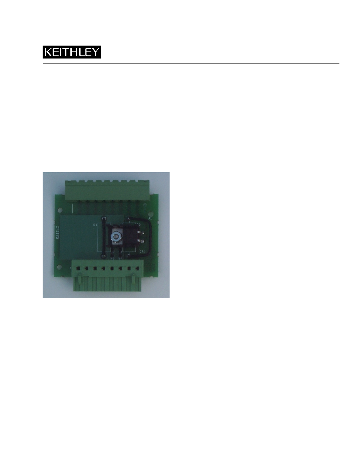
Control Adapter. The Model 2510-RH (shown in Figure 1) allows the Model 2510 TEC SourceMeter to be used with a resistive
heater instead of a thermoelectric cooler.
Figure 1
2510-RH
Installation and connections
With the power off, connect the Model 2510-RH to the Model 2510 TEC SourceMeter rear panel INPUT/OUTPUT connector
(see Figure 2 for location). Connections can be made as outlined in Section 2 of the Model 2510 User’s Manual. Simply connect
the resistive heater to the equivalent Model 2510-RH OUTPUT terminals in place of the thermoelectric cooler shown on input/
output connection diagrams. Make sensor connections to equivalent Model 2510-RH INPUT terminals as needed.
PA-743 Rev. A / 9-00
Page 2

2
WARNING:NO INTERNAL OPERATOR SERVICABLE PARTS,SERVICE BY QUALIFIED PERSONNEL ONLY.
CAUTION:FOR CONTINUED PROTECTION AGAINST FIRE HAZARD,REPLACE FUSE WITH SAME TYPE AND RATING.
Figure 2
Connector location for Model 2510-RH installation
Connect 2510-RH to
INPUT/OUTPUT Connector.
Connect resistive heater to
OUTPUT terminals in place of TEC.
CAT I
!
OUTPUT INPUT
F+ S+ S- F- F+ F- S+ S-
ISOLATION FROM EARTH: 30V MAX.
MADE IN
U.S.A.
ENABLE-DIG I/O
IEEE-488
(ENTER IEEE ADDRESS
WITH FRONT PANEL MENU)
LINE FUSE
SLOWBLOW
2.5A, 250V
!
LINE RATING
100-240VAC
90VA MAX
RS-232
120
50, 60 HZ
TRIGGER
LINK
Model 2510 TEC SourceMeter
Operation
To operate, turn on the Model 2510 power and set up operating modes as desired. With the Model 2510-RH installed, current
will flow through the resistive heater when the system calls for heat, and no current will flow through the heater when the system
calls for cooling, allowing the resistive heater to cool through radiation, conduction, or convection.
Refer to the Model 2510 User’s Manual for detailed operating information.
Parts list
Table 1 summarizes Model 2510-RH parts.
Table 1
Model 2510-RH parts list
Circuit
Quantity
1
1
1
1
1
1
designation Description Keithley part no.
4-40 Kep nut
4-40 × 3/8 Phillips pan head screw
CR1
J1
P1
Diode, barrier, MBR745
Connector
Connector
Heat sink
4-40KEPNUT
4-40 × 3/8 PPHSEN
RF-65
CS-834
CS-983-8
HS-33
 Loading...