

Page 1

Models 2500 and 2502 Photodiode Meter
A GREATER MEASURE OF CONFIDENCE
User’s Manual
Page 2

WARRANTY
Keithley Instruments, Inc. warrants this product to be free from defects in material and workmanship for a
period of 1 year from date of shipment.
Keithley Instruments, Inc. warrants the following items for 90 days from the date of shipment: probes, cables,
rechargeable batteries, diskettes, and documentation.
During the warranty period, we will, at our option, either repair or replace any product that proves to be defective.
To exercise this warranty, write or call your local Keithley representative, or contact Keithley headquarters in
Cleveland, Ohio. You will be given prompt assistance and return instructions. Send the product, transportation
prepaid, to the indicated service facility. Repairs will be made and the product returned, transportation prepaid.
Repaired or replaced products are warranted for the balance of the original warranty period, or at least 90 days.
LIMITATION OF WARRANTY
This warranty does not apply to defects resulting from product modification without Keithley’s express written
consent, or misuse of any product or part. This warranty also does not apply to fuses, software, non-rechargeable
batteries, damage from battery leakage, or problems arising from normal wear or failure to follow instructions.
THIS WARRANTY IS IN LIEU OF ALL OTHER WARRANTIES, EXPRESSED OR IMPLIED, INCLUDING ANY IMPLIED WARRANTY OF MERCHANTABILITY OR FITNESS FOR A PARTICULAR USE.
THE REMEDIES PROVIDED HEREIN ARE BUYER’S SOLE AND EXCLUSIVE REMEDIES.
NEITHER KEITHLEY INSTRUMENTS, INC. NOR ANY OF ITS EMPLOYEES SHALL BE LIABLE FOR
ANY DIRECT, INDIRECT, SPECIAL, INCIDENTAL OR CONSEQUENTIAL DAMAGES ARISING OUT OF
THE USE OF ITS INSTRUMENTS AND SOFTWARE EVEN IF KEITHLEY INSTRUMENTS, INC., HAS
BEEN ADVISED IN ADVANCE OF THE POSSIBILITY OF SUCH DAMAGES. SUCH EXCLUDED DAMAGES SHALL INCLUDE, BUT ARE NOT LIMITED TO: COSTS OF REMOVAL AND INSTALLATION,
LOSSES SUSTAINED AS THE RESULT OF INJURY TO ANY PERSON, OR DAMAGE TO PROPERTY.
Keithley Instruments, Inc.
Sales Offices: BELGIUM: Bergensesteenweg 709 • B-1600 Sint-Pieters-Leeuw • 02-363 00 40 • Fax: 02/363 00 64
CHINA: Yuan Chen Xin Building, Room 705 • 12 Yumin Road, Dewai, Madian • Beijing 100029 • 8610-6202-2886 • Fax: 8610-6202-2892
FINLAND: Tietäjäntie 2 • 02130 Espoo • Phone: 09-54 75 08 10 • Fax: 09-25 10 51 00
FRANCE: 3, allée des Garays • 91127 Palaiseau Cédex • 01-64 53 20 20 • Fax: 01-60 11 77 26
GERMANY: Landsberger Strasse 65 • 82110 Germering • 089/84 93 07-40 • Fax: 089/84 93 07-34
GREAT BRITAIN: Unit 2 Commerce Park, Brunel Road • Theale • Berkshire RG7 4AB • 0118 929 7500 • Fax: 0118 929 7519
INDIA: Flat 2B, Willocrissa • 14, Rest House Crescent • Bangalore 560 001 • 91-80-509-1320/21 • Fax: 91-80-509-1322
ITALY: Viale San Gimignano, 38 • 20146 Milano • 02-48 39 16 01 • Fax: 02-48 30 22 74
JAPAN: New Pier Takeshiba North Tower 13F • 11-1, Kaigan 1-chome • Minato-ku, Tokyo 105-0022 • 81-3-5733-7555 • Fax: 81-3-5733-7556
KOREA: 2FL., URI Building • 2-14 Yangjae-Dong • Seocho-Gu, Seoul 137-888 • 82-2-574-7778 • Fax: 82-2-574-7838
NETHERLANDS: Postbus 559 • 4200 AN Gorinchem • 0183-635333 • Fax: 0183-630821
SWEDEN: c/o Regus Business Centre • Frosundaviks Allé 15, 4tr • 169 70 Solna • 08-509 04 679 • Fax: 08-655 26 10
SWITZERLAND: Kriesbachstrasse 4 • 8600 Dübendorf • 01-821 94 44 • Fax: 01-820 30 81
TAIWAN: 1FL., 85 Po Ai Street • Hsinchu, Taiwan, R.O.C. • 886-3-572-9077• Fax: 886-3-572-9031
28775 Aurora Road • Cleveland, Ohio 44139 • 440-248-0400 • Fax: 440-248-6168
1-888-KEITHLEY (534-8453) • www.keithley.com
4/02
Page 3

Models 2500 and 2502 Photodiode Meter
User’s Manual
©2000, Keithley Instruments, Inc.
All rights reserved.
Cleveland, Ohio, U.S.A.
Third Printing, June 2002
Document Number: 2500-900-01 Rev. C
Page 4

Manual Print History
The print history shown below lists the printing dates of all Revisions and Addenda created
for this manual. The Revision Level letter increases alphabetically as the manual undergoes
subsequent updates. Addenda, which are released between Revisions, contain important
change information that the user should incorporate immediately into the manual. Addenda
are numbered sequentially. When a new Revision is created, all Addenda associated with the
previous Revision of the manual are incorporated into the new Revision of the manual. Each
new Revision includes a revised copy of this print history page.
Revision A (Document Number 2500-900-01)..............................................................August 2000
Revision B (Document Number 2500-900-01).................................................................April 2001
Revision C (Document Number 2500-900-01)..................................................................June 2002
All Keithley product names are trademarks or registered trademarks of Keithley Instruments, Inc.
Other brand names are trademarks or registered trademarks of their respective holders.
Page 5

S
afety Precautions
The following safety precautions should be observed before using this product and any associated instrumentation. Although
some instruments and accessories would normally be used with non-hazardous voltages, there are situations where hazardous
conditions may be present.
This product is intended for use by qualified personnel who recognize shock hazards and are familiar with the safety precautions
required to avoid possible injury. Read and follow all installation, operation, and maintenance information carefully before using the product. Refer to the manual for complete product specifications.
If the product is used in a manner not specified, the protection provided by the product may be impaired.
The types of product users are:
Responsible body
ment is operated within its specifications and operating limits, and for ensuring that operators are adequately trained.
Operators
instrument. They must be protected from electric shock and contact with hazardous live circuits.
Maintenance personnel
voltage or replacing consumable materials. Maintenance procedures are described in the manual. The procedures explicitly state
if the operator may perform them. Otherwise, they should be performed only by service personnel.
Service personnel
trained service personnel may perform installation and service procedures.
Keithley products are designed for use with electrical signals that are rated Installation Category I and Installation Category II,
as described in the International Electrotechnical Commission (IEC) Standard IEC 60664. Most measurement, control, and data
I/O signals are Installation Category I and must not be directly connected to mains voltage or to voltage sources with high transient over-voltages. Installation Category II connections require protection for high transient over-voltages often associated with
local AC mains connections. Assume all measurement, control, and data I/O connections are for connection to Category I sources unless otherwise marked or described in the Manual.
Exercise extreme caution when a shock hazard is present. Lethal voltage may be present on cable connector jacks or test fixtures.
The American National Standards Institute (ANSI) states that a shock hazard exists when voltage levels greater than 30V RMS,
42.4V peak, or 60VDC are present.
circuit before measuring.
Operators of this product must be protected from electric shock at all times. The responsible body must ensure that operators
are prevented access and/or insulated from every connection point. In some cases, connections must be exposed to potential
human contact. Product operators in these circumstances must be trained to protect themselves from the risk of electric shock.
If the circuit is capable of operating at or above 1000 volts,
Do not connect switching cards directly to unlimited power circuits. They are intended to be used with impedance limited sources. NEVER connect switching cards directly to AC mains. When connecting sources to switching cards, install protective devices to limit fault current and voltage to the card.
Before operating an instrument, make sure the line cord is connected to a properly grounded power receptacle. Inspect the connecting cables, test leads, and jumpers for possible wear, cracks, or breaks before each use.
When installing equipment where access to the main power cord is restricted, such as rack mounting, a separate main input power disconnect device must be provided, in close proximity to the equipment and within easy reach of the operator.
For maximum safety, do not touch the product, test cables, or any other instruments while power is applied to the circuit under
test. ALWAYS remove power from the entire test system and discharge any capacitors before: connecting or disconnecting ca-
is the individual or group responsible for the use and maintenance of equipment, for ensuring that the equip-
use the product for its intended function. They must be trained in electrical safety procedures and proper use of the
perform routine procedures on the product to keep it operating properly, for example, setting the line
are trained to work on live circuits, and perform safe installations and repairs of products. Only properly
A good safety practice is to expect that hazardous voltage is present in any unknown
no conductive part of the circuit may be exposed.
5/02
Page 6

bles or jumpers, installing or removing switching cards, or making internal changes, such as installing or removing jumpers.
Do not touch any object that could provide a current path to the common side of the circuit under test or power line (earth) ground. Al-
ways make measurements with dry hands while standing on a dry, insulated surface capable of withstanding the voltage being measured.
The instrument and accessories must be used in accordance with its specifications and operating instructions or the safety of the
equipment may be impaired.
Do not exceed the maximum signal levels of the instruments and accessories, as defined in the specifications and operating in-
formation, and as shown on the instrument or test fixture panels, or switching card.
When fuses are used in a product, replace with same type and rating for continued protection against fire hazard.
Chassis connections must only be used as shield connections for measuring circuits, NOT as safety earth ground connections.
If you are using a test fixture, keep the lid closed while power is applied to the device under test. Safe operation requires the use
of a lid interlock.
If or is present, connect it to safety earth ground using the wire recommended in the user documentation.
!
The symbol on an instrument indicates that the user should refer to the operating instructions located in the manual.
The symbol on an instrument shows that it can source or measure 1000 volts or more, including the combined effect of
normal and common mode voltages. Use standard safety precautions to avoid personal contact with these voltages.
The
WARNING
information very carefully before performing the indicated procedure.
The
CAUTION
ranty.
Instrumentation and accessories shall not be connected to humans.
Before performing any maintenance, disconnect the line cord and all test cables.
To maintain protection from electric shock and fire, replacement components in mains circuits, including the power transformer,
test leads, and input jacks, must be purchased from Keithley Instruments. Standard fuses, with applicable national safety approvals, may be used if the rating and type are the same. Other components that are not safety related may be purchased from
other suppliers as long as they are equivalent to the original component. (Note that selected parts should be purchased only
through Keithley Instruments to maintain accuracy and functionality of the product.) If you are unsure about the applicability
of a replacement component, call a Keithley Instruments office for information.
To clean an instrument, use a damp cloth or mild, water based cleaner. Clean the exterior of the instrument only. Do not apply
cleaner directly to the instrument or allow liquids to enter or spill on the instrument. Products that consist of a circuit board with
no case or chassis (e.g., data acquisition board for installation into a computer) should never require cleaning if handled according to instructions. If the board becomes contaminated and operation is affected, the board should be returned to the factory for
proper cleaning/servicing.
heading in a manual explains dangers that might result in personal injury or death. Always read the associated
heading in a manual explains hazards that could damage the instrument. Such damage may invalidate the war-
Page 7

Table of Contents
1 Getting Started
General information ................................................................... 1-2
Warranty information .......................................................... 1-2
Contact information ............................................................ 1-2
Manual addenda .................................................................. 1-2
Safety symbols and terms ................................................... 1-2
Inspection ............................................................................ 1-3
Options and accessories ...................................................... 1-3
Product overview ........................................................................ 1-5
Front and rear panel familiarization ........................................... 1-6
Front panel summary .......................................................... 1-6
Rear panel summary ........................................................... 1-8
Power-up .................................................................................. 1-10
Line voltage selection ....................................................... 1-10
Line power connection ...................................................... 1-10
Power-up sequence ........................................................... 1-11
System identification ......................................................... 1-11
Line frequency setting ....................................................... 1-12
Fuse replacement .............................................................. 1-12
Display ..................................................................................... 1-13
Display format .................................................................. 1-13
CHANNEL SELECT key ................................................. 1-14
DISPLAY TOGGLE key ................................................... 1-14
Status and error messages ................................................. 1-14
Disabling front panel display ............................................ 1-14
Remote display programming ........................................... 1-15
Front panel tests ................................................................ 1-15
Default settings ......................................................................... 1-16
Saving and restoring user setups ....................................... 1-16
Power-on configuration ..................................................... 1-16
Factory default settings ..................................................... 1-16
Remote setups ................................................................... 1-19
Manuals ........................................................................ 1-3
Triax cables and adapters ............................................. 1-3
Interface cables ............................................................ 1-4
Rack mount kits ........................................................... 1-4
Carrying case ............................................................... 1-4
Front panel line frequency ......................................... 1-12
Remote command line frequency .............................. 1-12
Front panel control ..................................................... 1-14
Saving setups ............................................................. 1-16
Restoring setups ......................................................... 1-16
Page 8

Menus ....................................................................................... 1-20
Main menu ......................................................................... 1-20
Rules to navigate menus .................................................... 1-23
Editing voltage bias values ................................................ 1-24
Configuration menus ......................................................... 1-24
2 Connections
Connection precautions .............................................................. 2-2
INPUT and OUTPUT connectors .............................................. 2-2
Connector terminals .................................................................... 2-3
Triax INPUT connectors ..................................................... 2-3
OUTPUT connectors ........................................................... 2-3
Output enable .............................................................................. 2-4
Photodiode connections .............................................................. 2-4
Typical connections ............................................................. 2-4
Equivalent circuit ................................................................. 2-6
Connection considerations .................................................. 2-6
Ground connect mode connections ..................................... 2-7
Alternate connecting methods ................................................... 2-9
Current measurement connections ...................................... 2-9
Voltage source connections ............................................... 2-10
Analog output connections (Model 2502 only) ........................ 2-11
Analog output connector terminals ................................... 2-11
Non-isolated connections .................................................. 2-12
Isolated connections .......................................................... 2-13
Equivalent circuits ............................................................. 2-14
3 Basic Operation
Operation overview .................................................................... 3-2
Measurement and voltage bias capabilities ......................... 3-2
Ranges ................................................................................. 3-2
Compliance .......................................................................... 3-3
Basic circuit configuration .................................................. 3-3
Operation considerations ............................................................ 3-4
Warm-up .............................................................................. 3-4
Auto zero ............................................................................. 3-4
Front panel auto zero .................................................... 3-4
Remote command auto zero ......................................... 3-4
Source delay ........................................................................ 3-5
Auto delay period ......................................................... 3-5
Output slew time .......................................................... 3-6
Manual delay ................................................................ 3-6
Front panel source delay .............................................. 3-7
Remote command source delay ................................... 3-7
Page 9

Ground connect mode ......................................................... 3-8
Front panel ground connect ......................................... 3-8
Remote command ground connect .............................. 3-8
Basic measurement procedure .................................................. 3-10
Output control ................................................................... 3-10
Basic measurement circuit configuration .......................... 3-10
Front panel measurement procedure ................................. 3-11
Step 1. Select measurement channel and range. ........ 3-11
Step 2. Select source channel and set source level. ... 3-11
Step 3. Turn source outputs on. ................................. 3-12
Step 4. Observe readings on the display. ................... 3-12
Step 5. Turn source output off. .................................. 3-12
Remote command measurement procedure ...................... 3-12
Basic measurement and voltage source commands ... 3-12
Measurement programming example ........................ 3-13
Using the analog outputs (Model 2502 only) ........................... 3-14
4 Photodiode Measurements
Configuring measurements ........................................................ 4-2
Measurement configuration menu ....................................... 4-2
Configuring measurements ................................................. 4-3
Optical power ...................................................................... 4-3
Front panel photodiode measurements ...................................... 4-4
Photodiode measurement circuit configuration .................. 4-4
Front panel photodiode measurement procedure ................ 4-4
Step 1. Configure measurement functions. .................. 4-4
Step 2. Set bias voltage source values. ........................ 4-5
Step 3. Turn source outputs on. ................................... 4-5
Step 4. Observe readings on the display. ..................... 4-5
Step 5. Turn source outputs off. ................................... 4-5
Remote photodiode measurements ............................................ 4-5
Photodiode measurement commands .................................. 4-5
Photodiode measurement programming example ............... 4-7
5 Measurement Concepts
Source-delay-measure cycle ....................................................... 5-2
Overview ............................................................................. 5-2
Triggering ............................................................................ 5-2
Delay phase ......................................................................... 5-3
Measurement time ............................................................... 5-3
Sweep waveforms ...................................................................... 5-4
Staircase sweeps .................................................................. 5-4
Custom sweep ..................................................................... 5-4
SDM cycle during sweeps .................................................. 5-5
Page 10

Typical sweep applications .................................................. 5-5
Sweep data storage .............................................................. 5-5
Bias source operating boundaries ............................................... 5-6
Limit lines ........................................................................... 5-6
Loading effects .................................................................... 5-6
Data flow ..................................................................................... 5-8
Basic readings ..................................................................... 5-8
Data storage enabled ........................................................... 5-8
Limit test enabled ................................................................ 5-8
6 Range, Digits, Speed, and Filters
Range and digits ......................................................................... 6-2
Measurement range ............................................................. 6-2
Available ranges ........................................................... 6-2
Maximum readings ...................................................... 6-2
Manual ranging ............................................................ 6-2
Auto ranging ................................................................ 6-3
Auto range limits .......................................................... 6-3
Auto range operation with range limits ........................ 6-3
Digits ................................................................................... 6-4
Setting display resolution ............................................. 6-4
Remote range and digits programming ............................... 6-4
Range and digits programming example ...................... 6-5
Speed .......................................................................................... 6-5
Setting speed ....................................................................... 6-6
SPEED-ACCURACY MENU ..................................... 6-6
Remote speed programming ................................................ 6-7
Speed commands .......................................................... 6-7
Speed programming example ....................................... 6-7
Filters .......................................................................................... 6-7
Filter stages ......................................................................... 6-7
Repeat filter .................................................................. 6-8
Median filter ................................................................. 6-8
Moving filter ............................................................... 6-10
Filter configuration ............................................................ 6-11
Filter control ...................................................................... 6-12
Remote filter programming ............................................... 6-13
Filter commands ......................................................... 6-13
Filter programming example ...................................... 6-14
Page 11

7 Relative, Math, Ratio, and Delta
Relative ....................................................................................... 7-2
Front panel rel ..................................................................... 7-2
Enabling and disabling rel ........................................... 7-2
Defining a rel value ...................................................... 7-2
Using REL in the dual-channel mode .......................... 7-3
Remote rel programming .................................................... 7-3
Rel commands ............................................................. 7-3
Rel programming example .......................................... 7-4
Measurement math functions ..................................................... 7-4
Math functions .................................................................... 7-4
I/V ................................................................................ 7-4
V/I ................................................................................ 7-5
MX + B ........................................................................ 7-5
Electrical power ........................................................... 7-5
Optical power ............................................................... 7-5
Front panel math functions ................................................. 7-6
Remote math functions ....................................................... 7-7
Math function programming example ................................ 7-8
RATIO and DELTA .................................................................... 7-8
RATIO functions ................................................................. 7-8
MSR1/MSR2 ............................................................... 7-8
MSR2/MSR1 ............................................................... 7-9
DELTA functions ................................................................ 7-9
MSR1-MSR2 ............................................................... 7-9
MSR2-MSR1 ............................................................... 7-9
Front panel RATIO and DELTA configuration ................. 7-10
Remote RATIO and DELTA ............................................. 7-11
RATIO and DELTA function programming example ....... 7-12
8 Data Store
Data store overview .................................................................... 8-2
Front panel data store ................................................................. 8-2
Storing readings .................................................................. 8-2
Recalling readings ............................................................... 8-2
Buffer location number ................................................ 8-3
Timestamp ................................................................... 8-3
Displaying other buffer readings ................................. 8-3
Buffer statistics ................................................................... 8-4
Minimum and maximum ............................................. 8-4
Peak-to-peak ................................................................ 8-4
Average ........................................................................ 8-4
Standard deviation ....................................................... 8-4
Page 12

Timestamp format ............................................................... 8-5
Timestamp accuracy ............................................................ 8-5
Buffer considerations .......................................................... 8-5
Using :TRACe commands to store data ....................... 8-5
Using :READ? to store data ......................................... 8-6
Remote command data store ...................................................... 8-6
Data store commands .......................................................... 8-6
Data store programming example ....................................... 8-7
9 Sweep Operation
Sweep types ................................................................................ 9-2
Linear staircase sweep ......................................................... 9-2
Logarithmic staircase sweep ............................................... 9-3
Custom sweep ..................................................................... 9-4
Custom sweep examples .............................................. 9-5
Configuring and running a sweep ............................................... 9-6
Front panel sweep operation ............................................... 9-6
Configuring a sweep ..................................................... 9-6
Setting delay ................................................................. 9-7
Trigger count and sweep points ................................... 9-8
Performing sweeps .............................................................. 9-8
Performing a linear staircase sweep ............................. 9-8
Performing a log staircase sweep ................................. 9-9
Performing a custom sweep ....................................... 9-11
Remote sweep operation ................................................... 9-12
Staircase sweep commands ........................................ 9-12
Staircase sweep programming example ..................... 9-13
Custom sweep commands .......................................... 9-14
Custom sweep programming example ....................... 9-15
10 Triggering
Trigger model (front panel operation) ...................................... 10-2
Idle ..................................................................................... 10-2
Event detection .................................................................. 10-4
Arm layer ................................................................... 10-4
Trigger layer ............................................................... 10-5
Trigger delay ..................................................................... 10-5
Source, delay, and measure actions ................................... 10-5
Counters ............................................................................ 10-6
Output triggers ................................................................... 10-6
Bench defaults ................................................................... 10-7
Operation summary ........................................................... 10-7
Page 13

Trigger link ............................................................................... 10-8
Input trigger requirements ................................................. 10-8
Output trigger specifications ............................................. 10-9
External triggering example .............................................. 10-9
Model 2500 setup .................................................... 10-11
Switching mainframe setup ..................................... 10-12
Operation ................................................................. 10-12
Configuring triggering ............................................................ 10-14
CONFIGURE TRIGGER menu ..................................... 10-14
Remote triggering .................................................................. 10-17
Trigger model (remote operation) ................................... 10-17
Idle and initiate ............................................................... 10-17
Event detection ................................................................ 10-19
Arm layer ........................................................................ 10-19
Trigger layer .................................................................... 10-20
Trigger delay ................................................................... 10-21
Source, delay, and measure actions ................................. 10-21
Counters .......................................................................... 10-22
Output triggers ................................................................ 10-22
GPIB defaults .................................................................. 10-23
Operation summary ......................................................... 10-23
Remote trigger commands .............................................. 10-24
Remote trigger example .................................................. 10-25
11 Limit Testing
Types of limits .......................................................................... 11-2
Pass/fail information ......................................................... 11-2
Data flow ........................................................................... 11-3
Limit test feeds .................................................................. 11-3
Limit 1 and 2 tests (compliance) ....................................... 11-3
Limit 3 to 6 tests ............................................................... 11-3
Limit test modes ................................................................ 11-3
Binning .............................................................................. 11-4
Operation overview .................................................................. 11-4
Grading mode .................................................................... 11-4
Binning control .......................................................... 11-6
Pass condition ............................................................ 11-7
Fail condition ............................................................. 11-7
Sorting mode ..................................................................... 11-8
Binning ...................................................................... 11-8
Page 14

Binning systems ...................................................................... 11-10
Handler interface ............................................................. 11-10
Digital I/O connector ............................................... 11-10
Digital output lines ................................................... 11-10
SOT line ................................................................... 11-11
/OE line .................................................................... 11-11
Handler types ................................................................... 11-11
Category pulse component handler .......................... 11-11
Category register component handler ...................... 11-12
Basic binning systems ..................................................... 11-12
Single-element device binning ........................................ 11-12
Multiple-element device binning ..................................... 11-14
Digital output clear pattern ..................................................... 11-14
Enabling auto-clear .................................................. 11-14
Auto-clear timing ............................................................ 11-15
Configuring and performing limit tests .................................. 11-16
Configuring limit tests ..................................................... 11-16
Performing limit tests ...................................................... 11-18
Step 1. Configure test system. .................................. 11-18
Step 2. Configure bias source and measure
functions. ............................................................. 11-18
Step 3. Configure limit tests. .................................... 11-19
Step 4. Turn output on. ............................................. 11-19
Step 5. Start testing process. .................................... 11-19
Step 6. Stop testing process. ..................................... 11-19
Remote limit testing ............................................................... 11-20
Limit commands .............................................................. 11-20
Limit test programming example .................................... 11-21
12 Digital I/O Port, Output Enable, and Output Configuration
Digital I/O port ......................................................................... 12-2
Port configuration .............................................................. 12-2
Digital output lines ..................................................... 12-3
SOT line ..................................................................... 12-3
EOT/BUSY line ......................................................... 12-3
+5V output ................................................................. 12-3
Digital output configuration .............................................. 12-4
Sink operation ............................................................ 12-4
Source operation ........................................................ 12-5
Controlling digital output lines ......................................... 12-5
Front panel digital output control ............................... 12-5
Remote digital output control .................................... 12-6
Page 15

Output enable ........................................................................... 12-6
Front panel output configuration .............................................. 12-8
Configure OUTPUT menu ................................................ 12-8
Remote output configuration .................................................... 12-9
Output configuration commands ....................................... 12-9
Output configuration programming example .................. 12-10
13 Remote Operations
Differences: remote vs. local operation .................................... 13-2
Local-to-remote transition ................................................ 13-2
Remote-to-local transition ................................................ 13-2
Selecting an interface ............................................................... 13-2
GPIB operation ........................................................................ 13-3
GPIB standards ................................................................. 13-3
GPIB connections ............................................................. 13-4
Primary address ................................................................. 13-6
General bus commands ............................................................ 13-6
REN (remote enable) ........................................................ 13-7
IFC (interface clear) .......................................................... 13-7
LLO (local lockout) .......................................................... 13-7
GTL (go to local) .............................................................. 13-7
DCL (device clear) ............................................................ 13-8
SDC (selective device clear) ............................................. 13-8
GET (group execute trigger) ............................................. 13-8
SPE, SPD (serial polling) .................................................. 13-8
Front panel GPIB operation ..................................................... 13-9
Error and status messages ................................................. 13-9
GPIB status indicators ....................................................... 13-9
REM ........................................................................... 13-9
TALK ......................................................................... 13-9
LSTN ......................................................................... 13-9
SRQ .......................................................................... 13-10
LOCAL key .................................................................... 13-10
Programming syntax .............................................................. 13-10
Command words ............................................................. 13-10
Commands and command parameters ..................... 13-10
Query commands ............................................................ 13-12
Case sensitivity ............................................................... 13-13
Long-form and short-form versions ................................ 13-13
Short-form rules .............................................................. 13-13
Program messages ........................................................... 13-14
Single command messages ...................................... 13-14
Multiple command messages ................................... 13-14
Command path rules ................................................ 13-15
Page 16

Using common and SCPI commands in the
same message ....................................................... 13-15
Program message terminator (PMT) ........................ 13-15
Command execution rules ........................................ 13-15
Response messages ......................................................... 13-16
Sending a response message .................................... 13-16
Multiple response messages ..................................... 13-16
Response message terminator (RMT) ...................... 13-16
Message exchange protocol ............................................. 13-16
RS-232 interface operation ..................................................... 13-17
Sending and receiving data .............................................. 13-17
Baud rate ......................................................................... 13-17
Data bits and parity ......................................................... 13-17
Terminator ....................................................................... 13-18
Flow control (signal handshaking) .................................. 13-18
RS-232 connections ......................................................... 13-18
Error messages ................................................................ 13-19
Programming example .................................................... 13-20
14 Status Structure
Overview .................................................................................. 14-2
Status byte and SRQ .......................................................... 14-2
Status register sets ............................................................. 14-2
Queues ............................................................................... 14-2
Clearing registers and queues ................................................... 14-4
Programming and reading registers .......................................... 14-5
Programming enable registers ........................................... 14-5
Reading registers ............................................................... 14-6
Status byte and service request (SRQ) ..................................... 14-7
Status byte register ............................................................ 14-8
Service request enable register .......................................... 14-9
Serial polling and SRQ ...................................................... 14-9
SPE, SPD (serial polling) ........................................... 14-9
Status byte and service request commands ..................... 14-10
Programming example - set MSS (B6) when
error occurs .......................................................... 14-10
Status register sets .................................................................. 14-11
Register bit descriptions .................................................. 14-11
Standard event register ............................................. 14-11
Operation event register ........................................... 14-13
Measurement event register ...................................... 14-14
Questionable event register ...................................... 14-16
Condition registers .......................................................... 14-17
Event registers ................................................................. 14-17
Page 17

Event enable registers ..................................................... 14-18
Programming example - program and read
register set ............................................................ 14-19
Queues .................................................................................... 14-19
Output queue ................................................................... 14-19
Error queue ...................................................................... 14-20
Programming example - read error queue ............... 14-21
15 Common Commands
Command summary ................................................................. 15-2
Command reference ................................................................. 15-3
*IDN? — identification query .......................................... 15-3
*OPC — operation complete ............................................ 15-3
*OPC? — operation complete query ................................ 15-3
*OPC programming example .................................... 15-4
*OPT? — option query ..................................................... 15-4
*SAV <NRf> — save ........................................................ 15-4
*RCL <NRf> — recall ..................................................... 15-4
*SAV, *RCL programming example ......................... 15-5
*RST — reset .................................................................... 15-5
*TRG — trigger ................................................................ 15-5
*TRG programming example .................................... 15-6
*TST? — self-test query ................................................... 15-6
*WAI — wait-to-continue ................................................. 15-6
16 SCPI Signal-Oriented Measurement Commands
Command summary ................................................................. 16-2
Configuring measurement function .......................................... 16-2
CONFigure:CURRent[:DC] ............................................. 16-2
Acquiring readings ................................................................... 16-3
FETCh? ............................................................................. 16-3
DATA[:LATest]? ............................................................... 16-4
READ? .............................................................................. 16-4
MEASure[:CURRent[:DC]]? ............................................ 16-5
17 SCPI Command Reference
Reference tables ....................................................................... 17-2
Calculate subsystems ............................................................. 17-22
CALCulate[1] and CALCulate2 ............................................ 17-23
Select math function ....................................................... 17-23
FORMat <name> ..................................................... 17-23
FORMat <name> ..................................................... 17-23
Page 18

Set MX + B parameters ................................................... 17-24
MBFactor <n> .......................................................... 17-24
MMFactor <n> ......................................................... 17-24
MUNits <name> ...................................................... 17-24
Set optical power parameters .......................................... 17-25
DC<n> ...................................................................... 17-25
RESP<n> .................................................................. 17-25
Enable and read math function result .............................. 17-26
STATe <b> ................................................................ 17-26
DATA? ...................................................................... 17-26
LATest? .................................................................... 17-26
CALCulate3 and CALCulate4 ............................................... 17-27
Select input path .............................................................. 17-27
FEED <name> .......................................................... 17-27
FEED <name> .......................................................... 17-27
Set or acquire relative value ............................................ 17-28
OFFSet <n> .............................................................. 17-28
ACQuire ................................................................... 17-28
Enable and read relative result ........................................ 17-28
STATe <b> ................................................................ 17-28
DATA? ...................................................................... 17-28
CALCulate5 ............................................................................ 17-29
Select RATIO calculation mode ...................................... 17-29
FORMat <name> ..................................................... 17-29
Enable and read RATIO result ........................................ 17-29
STATe <b> ................................................................ 17-29
DATA? ...................................................................... 17-29
CALCulate6 ............................................................................ 17-30
Select DELTA calculation mode ..................................... 17-30
FORMat <name> ..................................................... 17-30
Enable and read DELTA result ........................................ 17-30
STATe <b> ................................................................ 17-30
DATA? ...................................................................... 17-30
CALCulate7 ............................................................................ 17-31
Select input path .............................................................. 17-31
FEED <name> .......................................................... 17-31
Read limits data ............................................................... 17-32
DATA? ...................................................................... 17-32
LATest? .................................................................... 17-32
Configure and control limit tests ..................................... 17-32
COMPliance:FAIL <name> ..................................... 17-32
[:DATA] <n> ............................................................ 17-32
SOURce3 <NRf> | <NDN> ..................................... 17-33
PASS:SOURce3 <NRf> | NDN ............................... 17-35
STATe <b> ................................................................ 17-35
FAIL? ....................................................................... 17-36
Page 19

Composite testing ............................................................ 17-36
PASS:SOURce3 <NRf> | NDN ............................... 17-36
FAIL:SOURce3 <NRf> | <NDN> ........................... 17-37
BCONtrol <name> .................................................. 17-37
MODE <name> ....................................................... 17-38
Clear test results .............................................................. 17-38
[:IMMediate] ............................................................ 17-38
AUTO <b> ............................................................... 17-38
CALCulate8 ........................................................................... 17-39
Select statistic .................................................................. 17-39
FORMat <name> ..................................................... 17-39
Acquire statistic .............................................................. 17-39
DATA? ..................................................................... 17-39
DISPlay subsystem ................................................................ 17-40
Control display ................................................................ 17-40
DIGits <n> ............................................................... 17-40
ENABle <b> ............................................................ 17-40
MODE <name> ....................................................... 17-41
ATTRibutes? ............................................................ 17-41
Read display .................................................................... 17-42
DATA? ..................................................................... 17-42
Define :TEXT messages ................................................. 17-42
DATA <a> ................................................................ 17-42
STATe <b> ............................................................... 17-43
FORMat subsystem ................................................................ 17-43
Data format ..................................................................... 17-43
[:DATA] <type>[,length] ......................................... 17-43
Data elements .................................................................. 17-46
ELEMents <item list> ............................................. 17-46
SOURce3 <name> ................................................... 17-49
CALC data elements ....................................................... 17-49
CALCulate <item list> ............................................ 17-49
TRACe data elements ..................................................... 17-50
TRACe <item list> ................................................... 17-50
Byte order ........................................................................ 17-51
BORDer <name> ..................................................... 17-51
Status register format ...................................................... 17-51
SREGister <name> .................................................. 17-51
OUTPut subsystem ................................................................ 17-52
Turn source on or off ....................................................... 17-52
[:STATe] <b> ........................................................... 17-52
Output enable control ...................................................... 17-53
ENABle[:STATe] <b> .............................................. 17-53
TRIPped? ................................................................. 17-53
Page 20

SENSe subsystem ................................................................... 17-54
Select measurement range ............................................... 17-54
[:UPPer] <n> ............................................................ 17-54
Select auto range ............................................................. 17-55
AUTO <b> ............................................................... 17-55
LLIMit <n> .............................................................. 17-55
ULIMit <n> .............................................................. 17-55
Set measurement speed ................................................... 17-56
NPLCycles <n> ........................................................ 17-56
Configure and control filters ............................................ 17-57
Average filter commands .......................................... 17-57
COUNt <n> .............................................................. 17-57
[:STATe] <b> ............................................................ 17-57
TCONtrol <name> ................................................... 17-58
ADVanced:NTOLerance <n> ................................... 17-58
ADVanced[:STATe] <b> .......................................... 17-58
Median filter commands ........................................... 17-59
MEDian:RANK <NRf> ........................................... 17-59
MEDian[:STATe] <b> .............................................. 17-59
SOURce subsystem ................................................................ 17-60
SOURce[1] and SOURce2 .............................................. 17-60
Control source output on-off ........................................... 17-60
[:IMMediate] ............................................................ 17-60
MODE <name> ........................................................ 17-60
Select sourcing mode ...................................................... 17-61
MODE <name> ........................................................ 17-61
Select range ..................................................................... 17-61
RANGe <n> ............................................................. 17-61
AUTO <b> ............................................................... 17-62
Set amplitude for fixed source ......................................... 17-63
[:IMMediate][:AMPLitude] <n> .............................. 17-63
TRIGgered[:AMPLitude] <n> ................................. 17-64
Set delay .......................................................................... 17-65
DELay <n> ............................................................... 17-65
AUTO <b> ............................................................... 17-65
Select ground connect mode ........................................... 17-66
GCONnect <b> ........................................................ 17-66
Configure sweeps ............................................................ 17-66
RANGing <name> ................................................... 17-66
SPACing <name> ..................................................... 17-67
STARt <n> ................................................................ 17-67
STOP <n> ................................................................ 17-67
CENTer <n>.............................................................. 17-68
SPAN <n> ................................................................ 17-68
Page 21

STEP <n> ................................................................ 17-69
POINts <n> .............................................................. 17-70
DIRection <name> .................................................. 17-71
Configure list ................................................................... 17-71
VOLTage <NRf list> ................................................ 17-71
APPend <NRf list> .................................................. 17-72
POINts? .................................................................... 17-72
Sweep and list program examples ................................... 17-72
Linear voltage sweep ............................................... 17-72
List sweep ................................................................ 17-72
Logarithmic sweep ................................................... 17-73
SOURce3 ........................................................................ 17-74
Setting digital output ....................................................... 17-74
[:LEVel] <NRf> | <NDN> ....................................... 17-74
ACTual? ................................................................... 17-75
MODE <name> ....................................................... 17-75
BSTate <b> .............................................................. 17-76
BSIZe <n> ............................................................... 17-76
Clearing digital output .................................................... 17-76
[:IMMediate] ............................................................ 17-76
AUTO <b> ............................................................... 17-76
DELay <n> .............................................................. 17-77
STATus subsystem ................................................................. 17-78
Read event registers ........................................................ 17-78
[:EVENt]? ................................................................ 17-78
Program event enable registers ....................................... 17-78
ENABle <NDN> or <NRf> ..................................... 17-78
Read condition registers .................................................. 17-79
CONDition? ............................................................. 17-79
Select default conditions ................................................. 17-79
PRESet ..................................................................... 17-79
Error queue ...................................................................... 17-79
[:NEXT]? ................................................................. 17-79
CLEar ....................................................................... 17-79
ENABle <list> ......................................................... 17-80
DISable <list> .......................................................... 17-80
SYSTem subsystem ................................................................ 17-81
Default conditions ........................................................... 17-81
PRESet ..................................................................... 17-81
POSetup ................................................................... 17-81
Control auto zero ............................................................. 17-82
STATe <name> ........................................................ 17-82
Select power line frequency setting ................................ 17-82
LFRequency <freq> ................................................. 17-82
Page 22

Error queue ...................................................................... 17-82
[:NEXT]? ................................................................. 17-82
ALL? ........................................................................ 17-83
COUNt? ................................................................... 17-83
CODE[:NEXT]? ....................................................... 17-83
CODE:ALL? ............................................................ 17-83
CLEar ....................................................................... 17-83
Simulate key presses ....................................................... 17-84
KEY ......................................................................... 17-84
Read version of SCPI standard ........................................ 17-85
VERSion? ................................................................. 17-85
RS-232 interface .............................................................. 17-85
LOCal ....................................................................... 17-85
REMote .................................................................... 17-85
RWLock ................................................................... 17-86
Reset timestamp .............................................................. 17-86
RESet ....................................................................... 17-86
TRACe subsystem .................................................................. 17-87
Read and clear buffer ....................................................... 17-87
DATA? ...................................................................... 17-87
CLEar ....................................................................... 17-87
Configure and control buffer ........................................... 17-88
FREE? ...................................................................... 17-88
POINts <n> .............................................................. 17-88
ACTual? ................................................................... 17-88
CONTrol <name> .................................................... 17-89
Select timestamp format .................................................. 17-89
FORMat <name> ..................................................... 17-89
Trigger subsystem ................................................................... 17-90
Initiate source/measure cycle .......................................... 17-90
INITiate ................................................................... 17-90
Abort source/measure cycle ............................................ 17-90
ABORt ..................................................................... 17-90
Program trigger model .................................................... 17-91
COUNt <n> .............................................................. 17-91
DELay <n> ............................................................... 17-92
SOURce <name> ..................................................... 17-92
TIMer <n> ................................................................ 17-93
DIRection <name> ................................................... 17-93
INPut <event list> .................................................... 17-94
ILINe <NRf> ............................................................ 17-95
OLINe <NRf> .......................................................... 17-95
OUTPut <event list> ................................................ 17-96
Page 23

A Specifications
B Status and Error Messages
Introduction ............................................................................... B-2
Status and error messages ......................................................... B-2
Eliminating common SCPI errors ............................................. B-8
-113, Undefined header ............................................... B-8
-420, Query UNTERMINATED ................................. B-9
C Data Flow
Introduction ............................................................................... C-2
SENS1 and SENS2 ............................................................ C-3
INIT ............................................................................ C-3
FETCh? ....................................................................... C-3
READ? ........................................................................ C-3
CALCulate[1]:DATA? and CALCulate2:DATA? .............. C-4
CALCulate3:DATA? and CALCulate4:DATA? ................. C-4
CALCulate5:DATA? and CALCulate6:DATA? ................. C-4
CALCulate7:DATA? .......................................................... C-4
TRACe:DATA? .................................................................. C-4
CALCulate8:DATA? .......................................................... C-4
D IEEE-488 Bus Overview
Introduction ............................................................................... D-2
Bus description .......................................................................... D-3
Bus lines .................................................................................... D-5
Data lines ........................................................................... D-5
Bus management lines ....................................................... D-5
Handshake lines ................................................................. D-5
Bus commands .......................................................................... D-7
Uniline commands ............................................................. D-8
Universal multiline commands .......................................... D-8
Addressed multiline commands ......................................... D-9
Address commands ............................................................ D-9
Unaddress commands ........................................................ D-9
Common commands ........................................................ D-10
SCPI commands ............................................................... D-10
Command codes ............................................................... D-10
Typical command sequences ............................................ D-12
IEEE command groups .................................................... D-13
Interface function codes .......................................................... D-14
Page 24

E IEEE-488 and SCPI Conformance Information
Introduction ............................................................................... E-2
F Measurement Considerations
Low current measurements ........................................................ F-2
Leakage currents ................................................................ F-2
Noise and source impedance .............................................. F-2
DUT resistance ............................................................ F-2
Source capacitance ...................................................... F-3
Generated currents .............................................................. F-4
Offset currents ............................................................. F-4
Electrochemical effects ............................................... F-5
Humidity ..................................................................... F-5
Triboelectric effects ..................................................... F-5
Piezoelectric and stored charge effects ....................... F-5
Dielectric absorption ................................................... F-6
Voltage burden .................................................................... F-6
General measurement considerations ........................................ F-7
Ground loops ...................................................................... F-7
Light ................................................................................... F-8
Electrostatic interference .................................................... F-9
Magnetic fields ................................................................. F-10
Electromagnetic Interference (EMI) ................................ F-10
G GPIB 488.1 Protocol
Introduction ............................................................................... G-2
Selecting the 488.1 protocol ...................................................... G-2
Protocol differences ................................................................... G-3
Message exchange protocol (MEP) .................................... G-3
Using SCPI-based programs .............................................. G-3
Bus hold-off ........................................................................ G-4
Trigger-on-talk ................................................................... G-4
Message available ............................................................... G-4
General operation notes ...................................................... G-4
Page 25

H Example Programs
Introduction ............................................................................... H-2
Hardware requirements ...................................................... H-2
Software requirements ....................................................... H-2
General program instructions ............................................. H-2
Basic measurement program ..................................................... H-3
Photodiode measurement program ............................................ H-4
Data store program .................................................................... H-5
Linear sweep program ............................................................... H-6
Limit test program ..................................................................... H-7
Page 26

List of Illustrations
1 Getting Started
Figure 1-1 Front panel ............................................................................. 1-6
Figure 1-2 Model 2500 rear panel ........................................................... 1-8
Figure 1-3 Model 2502 rear panel ........................................................... 1-9
Figure 1-4 Main menu tree .................................................................... 1-22
2 Connections
Figure 2-1 Model 2500 rear panel showing INPUT and
OUTPUT connectors ......................................................... 2-2
Figure 2-2 INPUT connector terminals ................................................... 2-3
Figure 2-3 Typical photodiode connections ............................................ 2-5
Figure 2-4 Equivalent circuit of photodiode test connections ................. 2-6
Figure 2-5 Test connections using ground connect mode ....................... 2-7
Figure 2-6 Ground connect mode equivalent circuit ............................... 2-8
Figure 2-7 Stand-alone current measurement connections ...................... 2-9
Figure 2-8 Stand-alone voltage source connections .............................. 2-10
Figure 2-9 Analog output connector terminals ...................................... 2-11
Figure 2-10 Non-isolated analog output connections .............................. 2-12
Figure 2-11 Isolated analog output connections ...................................... 2-13
Figure 2-12 Analog output equivalent circuit with ground
connect disabled .............................................................. 2-14
Figure 2-13 Analog output equivalent circuit with ground
connect enabled ............................................................... 2-15
3 Basic Operation
Figure 3-1 Basic circuit configuration ..................................................... 3-3
Figure 3-2 Output slew time .................................................................... 3-6
Figure 3-3 Ground connect enabled ........................................................ 3-9
Figure 3-4 Ground connect disabled ....................................................... 3-9
Figure 3-5 Circuit configuration for basic measurements ..................... 3-10
4 Photodiode Measurements
Figure 4-1 Measurement configuration menu tree .................................. 4-2
Figure 4-2 Circuit configuration for photodiode measurements ............. 4-4
5 Measurement Concepts
Figure 5-1 Source-delay-measure (SDM) cycle ...................................... 5-2
Figure 5-2 Simplified trigger model ........................................................ 5-3
Figure 5-3 Basic sweep waveform types ................................................. 5-4
Figure 5-4 Bias source limit lines ............................................................ 5-6
Page 27

Figure 5-5 Loading effects ....................................................................... 5-7
Figure 5-6 Data flow front panel .............................................................. 5-9
Figure 5-7 CALC block data flow .......................................................... 5-10
6 Range, Digits, Speed, and Filters
Figure 6-1 Speed configuration menu tree ............................................... 6-6
Figure 6-2 2-stage filtering ....................................................................... 6-7
Figure 6-3 Repeat filter (count 10) ........................................................... 6-8
Figure 6-4 Median filter (rank 5) ............................................................. 6-9
Figure 6-5 Moving filter (count 10) ....................................................... 6-10
Figure 6-6 Configure filtering menu tree ............................................... 6-12
9 Sweep Operation
Figure 9-1 Linear staircase sweep ............................................................ 9-2
Figure 9-2 Logarithmic staircase sweep (example 5-point sweep
from 1 to 10 volts) .............................................................. 9-3
Figure 9-3 Custom pulse sweep ............................................................... 9-5
Figure 9-4 Custom sweep with different pulse widths ............................ 9-5
Figure 9-5 Sweep configuration menu tree .............................................. 9-7
10 Triggering
Figure 10-1 Trigger model (front panel operation) .................................. 10-3
Figure 10-2 Rear panel pinout ................................................................. 10-8
Figure 10-3 Trigger link input pulse specifications ................................. 10-8
Figure 10-4 Trigger link output pulse specifications ............................... 10-9
Figure 10-5 DUT test system ................................................................... 10-9
Figure 10-6 Trigger link connections ..................................................... 10-10
Figure 10-7 Operation model for triggering example ............................ 10-13
Figure 10-8 Configure trigger menu tree ............................................... 10-16
Figure 10-9 Trigger model (remote operation) ...................................... 10-18
Figure 10-10 Measure action ................................................................... 10-21
11 Limit Testing
Figure 11-1 Limit tests ............................................................................. 11-2
Figure 11-2 Grading mode limit testing ................................................... 11-5
Figure 11-3 Immediate binning ............................................................... 11-6
Figure 11-4 End binning .......................................................................... 11-6
Figure 11-5 Sorting mode limit testing .................................................... 11-9
Figure 11-6 Handler interface connections ............................................ 11-10
Figure 11-7 Binning system—single element devices ........................... 11-13
Figure 11-8 Binning system—multiple element devices ....................... 11-13
Figure 11-9 Digital output auto-clear timing example ........................... 11-15
Figure 11-10 Limits configuration menu tree .......................................... 11-18
Page 28

12 Digital I/O Port, Output Enable, and Output Configuration
Figure 12-1 Output Enable and digital I/O .............................................. 12-2
Figure 12-2 Sink operation ...................................................................... 12-4
Figure 12-3 Source operation .................................................................. 12-5
Figure 12-4 Using test fixture output ....................................................... 12-7
Figure 12-5 Output configuration menu tree ........................................... 12-8
13 Remote Operations
Figure 13-1 IEEE-488 connector ............................................................. 13-4
Figure 13-2 IEEE-488 connections ......................................................... 13-4
Figure 13-3 IEEE-488 and RS-232 connector location ........................... 13-5
Figure 13-4 RS-232 interface connector ............................................... 13-18
14 Status Structure
Figure 14-1 Model 2500 status register structure .................................... 14-3
Figure 14-2 16-bit status register ............................................................. 14-5
Figure 14-3 Status byte and service request (SRQ) ................................. 14-7
Figure 14-4 Standard event status .......................................................... 14-11
Figure 14-5 Operation event status ........................................................ 14-13
Figure 14-6 Measurement event status .................................................. 14-15
Figure 14-7 Questionable event status ................................................... 14-16
17 SCPI Command Reference
Figure 17-1 ASCII data format .............................................................. 17-44
Figure 17-2 IEEE-754 single precision data format (32 data bits) ........ 17-45
C Data Flow
Figure C-1 Data flow block diagram ....................................................... C-2
D IEEE-488 Bus Overview
Figure D-1 IEEE-488 bus configuration .................................................. D-4
Figure D-2 IEEE-488 handshake sequence ............................................. D-6
Figure D-3 Command codes .................................................................. D-11
F Measurement Considerations
Figure F-1 Voltage burden ....................................................................... F-6
Figure F-2 Power line ground loops ........................................................ F-7
Figure F-3 Eliminating ground loops ...................................................... F-8
Page 29

List of Tables
1 Getting Started
Table 1-1 Line fuses ............................................................................. 1-13
Table 1-2 Basic display commands ...................................................... 1-15
Table 1-3 Factory default settings ........................................................ 1-17
Table 1-4 Main menu ........................................................................... 1-20
Table 1-5 Measurement configuration menus ...................................... 1-25
Table 1-6 Source configuration menus ................................................. 1-26
Table 1-7 Rel, filter, and range configuration menus ........................... 1-26
Table 1-8 Limit configuration menu .................................................... 1-27
Table 1-9 Trigger configuration menu ................................................. 1-28
Table 1-10 Sweep, digits, speed, and data store configuration menus ... 1-29
Table 1-11 Output and display configuration menus ............................. 1-30
3 Basic Operation
Table 3-1 Current measurement ranges ................................................. 3-2
Table 3-2 Voltage source ranges ............................................................ 3-2
Table 3-3 Auto source delay .................................................................. 3-5
Table 3-4 Source delay commands ........................................................ 3-7
Table 3-5 Ground connect commands ................................................... 3-8
Table 3-6 Basic measurement and voltage source commands ............. 3-13
Table 3-7 Basic measurement command sequence .............................. 3-14
Table 3-8 Analog output voltage examples .......................................... 3-14
4 Photodiode Measurements
Table 4-1 MSR1 and MSR2 configuration menus ................................. 4-2
Table 4-2 Photodiode measurement commands ..................................... 4-6
Table 4-3 Basic measurement command sequence ................................ 4-8
6 Range, Digits, Speed, and Filters
Table 6-1 Current measurement ranges ................................................. 6-2
Table 6-2 Range and digits commands .................................................. 6-4
Table 6-3 Range and digits programming example ............................... 6-5
Table 6-4 Speed commands ................................................................... 6-7
Table 6-5 Filter configuration menu ..................................................... 6-12
Table 6-6 Filter commands .................................................................. 6-13
Table 6-7 Filter programming example ............................................... 6-14
Page 30

7 Relative, Math, Ratio, and Delta
Table 7-1 Rel commands ........................................................................ 7-3
Table 7-2 Rel programming example ..................................................... 7-4
Table 7-3 Measurement function configuration menu ........................... 7-6
Table 7-4 Math function commands ....................................................... 7-7
Table 7-5 Math function programming example .................................... 7-8
Table 7-6 RATIO and DELTA configuration menus ............................ 7-10
Table 7-7 RATIO and DELTA function commands ............................. 7-11
Table 7-8 RATIO and DELTA programming example ......................... 7-12
8 Data Store
Table 8-1 Data store commands ............................................................. 8-6
Table 8-2 Data store example ................................................................. 8-7
9 Sweep Operation
Table 9-1 Logarithmic sweep points ...................................................... 9-4
Table 9-2 Linear and log staircase sweep commands .......................... 9-12
Table 9-3 Staircase sweep programming example (photodiode test) ... 9-13
Table 9-4 Custom sweep commands .................................................... 9-14
Table 9-5 Custom sweep programming example ................................. 9-15
10 Triggering
Table 10-1 Remote trigger command ................................................... 10-24
Table 10-2 Remote triggering example ................................................ 10-25
11 Limit Testing
Table 11-1 Limit commands ................................................................. 11-20
Table 11-2 Limits test programming example ...................................... 11-22
12 Digital I/O Port, Output Enable, and Output Configuration
Table 12-1 Digital output line settings ................................................... 12-6
Table 12-2 Output configuration commands .......................................... 12-9
Table 12-3 Output configuration programming example ..................... 12-10
13 Remote Operations
Table 13-1 General bus commands ........................................................ 13-6
Table 13-2 RS-232 connector pinout .................................................... 13-19
Table 13-3 PC serial port pinout ........................................................... 13-19
Page 31

14 Status Structure
Table 14-1 Common and SCPI commands to reset registers
and clear queues ................................................................... 14-4
Table 14-2 Data format commands for reading status registers ............. 14-6
Table 14-3 Status byte and service request enable register
commands .......................................................................... 14-10
Table 14-4 Status byte programming example .................................... 14-10
Table 14-5 Condition register commands ............................................ 14-17
Table 14-6 Event register commands ................................................... 14-17
Table 14-7 Event enable register commands ....................................... 14-18
Table 14-8 Program and read register programming example ............. 14-19
Table 14-9 Error queue commands ...................................................... 14-21
15 Common Commands
Table 15-1 IEEE-488.2 common commands and queries ...................... 15-2
Table 15-2 *OPC programming example .............................................. 15-4
Table 15-3 *SAV, *RCL programming example ................................... 15-5
Table 15-4 *TRG programming example .............................................. 15-6
16 SCPI Signal-Oriented Measurement Commands
Table 16-1 Signal-oriented measurement command summary .............. 16-2
17 SCPI Command Reference
Table 17-1 CALCulate command summary .......................................... 17-3
Table 17-2 DISPlay command summary ............................................... 17-8
Table 17-3 FORMat command summary ............................................... 17-9
Table 17-4 OUTPut command summary ............................................. 17-10
Table 17-5 SENSe command summary ............................................... 17-11
Table 17-6 SOURce command summary ............................................. 17-13
Table 17-7 STATus command summary .............................................. 17-18
Table 17-8 SYSTem command summary ............................................ 17-19
Table 17-9 TRACe command summary .............................................. 17-20
Table 17-10 TRIGger command summary ............................................ 17-21
Page 32

B Status and Error Messages
Table B-1 Status and error messages ..................................................... B-3
D IEEE-488 Bus Overview
Table D-1 IEEE-488 bus command summary ........................................ D-7
Table D-2 Hexadecimal and decimal command codes ........................ D-10
Table D-3 Typical addressed multiline command sequence ................ D-12
Table D-4 Typical addressed common command sequence ................. D-12
Table D-5 IEEE command groups ....................................................... D-13
Table D-6 Model 2500 interface function codes .................................. D-14
E IEEE-488 and SCPI Conformance Information
Table E-1 IEEE-488 documentation requirements ................................ E-3
Table E-2 Coupled commands ............................................................... E-4
F Measurement Considerations
Table F-1 Minimum recommended source resistance values ................ F-3
Page 33

Getting Started
•
General information
tion, contact information, safety symbols and terms, inspection, and available options
and accessories.
•
Product overview
Meter.
•
Familiarization
•
Power-up
and the power-up sequence.
•
Display
•
Default settings
•
Menus
menus.
— Covers line power connection, line voltage settings, fuse replacement,
— Provides information about the Model 2500 display.
— Covers the main and configuration menus as well as rules to navigate
— Covers general information that includes warranty informa-
— Summarizes the features of the Model 2500 Dual Photodiode
— Summarizes the controls and connectors on the unit.
— Covers factory default setups and saving and recalling user setups.
1
Page 34

1-2 Getting Started Model 2500 and 2502 User’s Manual
General information
Warranty information
Warranty information is located at the front of this manual. Should your Model 2500
require warranty service, contact the Keithley representative or authorized repair facility
in your area for further information. When returning the instrument for repair, be sure to
fill out and include the service form at the back of this manual to provide the repair facility
with the necessary information.
Contact information
Worldwide phone numbers are listed at the front of this manual. If you have any questions,
please contact your local Keithley representative or call one of our Application Engineers
at 1-800-348-3735 (U.S. and Canada only).
Manual addenda
Any improvements or changes concerning the instrument or manual will be explained in
an addendum included with the manual. Be sure to note these changes and incorporate
them into the manual.
Safety symbols and terms
The following symbols and terms may be found on the instrument or used in this manual.
!
The symbol on an instrument indicates that the user should refer to the operating
instructions located in the manual.
The symbol on the instrument shows that high voltage may be present on the terminal(s). Use standard safety precautions to avoid personal contact with these voltages.
The
WARNING
sonal injury or death. Always read the associated information very carefully before performing the indicated procedure.
The
CAUTION
instrument. Such damage may invalidate the warranty.
heading used in this manual explains dangers that might result in per-
heading used in this manual explains hazards that could damage the
Page 35

Model 2500 and 2502 User’s Manual Getting Started 1-3
Inspection
The Model 2500 was carefully inspected electrically and mechanically before shipment.
After unpacking all items from the shipping carton, check for any obvious signs of physical damage that may have occurred during transit. (There may be a protective film over the
display lens, which can be removed.) Report any damage to the shipping agent immediately. Save the original packing carton for possible future shipment. The following items
are included with every Model 2500 Dual Photodiode Meter order:
• Model 2500 with line cord.
• Accessories as ordered.
• Certificate of calibration.
• User’s Manual.
• Service Manual
• Manual addenda, containing any improvements or changes to the instrument or
manual.
If an additional user’s manual is required, order the appropriate manual package (for
example, 2500-900-00). The manual packages include a manual and any pertinent
addenda.
Options and accessories
The following options and accessories are available from Keithley for use with the
Model 2500.
Manuals
Model 2500-902-00
nent addenda.
Triax cables and adapters
Model 7078-TRX-1
3-slot male triax connectors.
CS-751 Barrel Adapter
cables together. Both ends of the adapter are terminated with 3-lug female triax
connectors.
CS-1053 Barrel Adapter
male triax connectors.
Model 237-BNC-TRX Adapter
(guard disconnected). It is used to terminate a triax cable with a BNC plug.
Model 237-TRX-T Adapter
for use with triax cables.
— This manual package includes the service manual and any perti-
— This low-noise 12-inch triax cable is terminated at both ends with
— This is a barrel adapter that allows you to connect two triax
— This barrel adapter is terminated at both ends with 3-slot
— This is a male BNC to 3-lug female triax adapter
— This is a 3-slot male to dual 3-lug female triax tee adapter
Page 36

1-4 Getting Started Model 2500 and 2502 User’s Manual
Model 7078-TRX-BNC Adapter
This adapter lets you connect a BNC cable to the triax input of the Model 2500.
Model 237-TRX-TBC Connector
with cap for assembly of custom panels and interface connections.
— This is a 3-slot male triax to female BNC adapter.
— This is a 3-lug female triax bulkhead connector
Interface cables
Models 7007-1 and 7007-2 shielded GPIB cables
GPIB bus using shielded cables and connectors to reduce Electromagnetic Interference
(EMI). The Model 7007-1 is 1m long; the Model 7007-2 is 2m long.
Model 7009-5 shielded RS-232 cable
using shielded cables and connectors to reduce EMI.
Models 8501-1 and 8501-2 trigger link cables
instruments with Trigger Link connectors (e.g., Model 7001 Switch System). The Model
8501-1 is 1m long; the Model 8501-2 is 2m long.
Model 8502 trigger link adapter
the Model 2500 to instruments that use the standard BNC trigger connectors.
Model 8503 DIN to BNC trigger cable
meter Complete) and two (External Trigger) of the Model 2500 to instruments that use
BNC trigger connectors. The Model 8503 is 1m long.
— Connect the Model 2500 to computer serial port
— Lets you connect any of the six Trigger Link lines of
— Lets you connect Trigger Link lines one (Volt-
— Connect the Model 2500 to the
— Connect the Model 2500 to other
Rack mount kits
Model 4288-1 single fixed rack mount kit
19-inch rack.
Model 4288-2 side-by-side rack mount kit
428, 486, 487, 2000, 2001, 2002, 2010, 2015, 2016, 2400, 2410, 2420, 2430, 2500, 2510,
6430, 6517, 7001) side-by-side in a standard 19-inch rack.
Model 4288-3 side-by-side rack mount kit
side-by-side in a standard 19-inch rack.
Model 4288-4 side-by-side rack mount kit
instrument (Models 195A, 196, 220, 224, 230, 263, 595, 614, 617, 705, 740, 775, etc.)
side-by-side in a standard 19-inch rack.
Model 4288-5 dual fixed rack mounting kit
3½-inch high instrument (Model 182, 428, 486, 487, 2000, 2010, 2400, 2410, 2420, 2430,
or 7001) side-by-side in a standard 19-inch rack.
— Mounts a single Model 2500 in a standard
— Mounts two instruments (Models 182,
— Mounts a Model 2500 and a Model 199
— Mounts a Model 2500 and a 5.25-inch
— Mounts a Model 2500 and another
Carrying case
Model 1050 padded carrying case
and a shoulder strap.
— A carrying case for a Model 2500. Includes handles
Page 37

Model 2500 and 2502 User’s Manual Getting Started 1-5
Product overview
NOTE This manual covers both the Model 2500 and 2502, which ar e virtually identical
except for the addition of analog outputs on the Model 2502. All references to
the Model 2500 apply to the Model 2502 unless otherwise noted.
The Model 2500 combines two stable DC bias voltage sources with two low-noise ammeters for dual-channel, low-current photodiode measurements. The unit has 0.1% basic
measurement accuracy with up to 6½-digit resolution. At 5½-digit resolution, the
Model 2500 can transfer up to 475 readings per second over the GPIB, and up to 900 readings per second with 4½-digit resolution.
Each Model 2500 channel has the following measurement and voltage bias capabilities:
• Measure current from 1fA to 20mA.
• Source bias voltage from 500µV to 100V.
Some additional capabilities of the Model 2500 include:
• Sweep capabilities: linear and logarithmic staircase, and custom sweeps of up to 2500
points.
•Two hardware limit tests and four software limit tests with a built-in comparator for
pass/fail testing.
• Digital I/O for stand-alone binning operations or interface to component handler.
• Programming language and remote interfaces — The Model 2500 uses the SCPI programming language and two remote interface ports (IEEE-488/GPIB and RS-232C).
•Trigger-Link interface to Keithley Series 7000 switching hardware.
• Math functions — V/I, I/V, optical power, electrical power, ratio, delta, and offset
functions.
• Reading and setup storage — Up to 3000 5½-digit readings for each channel and
seven setups (five user defaults, factory default, *RST default) can be stored and
recalled.
• Closed-cover calibration — The instrument can be calibrated either from the front
panel or remote interface.
• The Model 2502 adds an analog output for each channel. Each analog output provides
a -10V to +10V output voltage analogous to the input current.
Page 38

1-6 Getting Started Model 2500 and 2502 User’s Manual
Front and rear panel familiarization
Front panel summary
The front panel of the Model 2500 is shown in Figure 1-1.
Figure 1-1
Front panel
2500 DUAL PHOTODIODE METER
CHANNEL
SELECT
DISPLAY
TOGGLE
POWER
MSR1
LOCAL
DIGITS SPEED
MSR2
0
1
REL
67
RATIO
DELTA
23
LIMIT
FILTER
8
STORE RECALL
9
SRC1 SRC2
45
SWEEP
TRIG
+/- 0000
MENU
CONFIG
EDIT
EXIT ENTER
RANGE
AUTO
RANGE
ON/OFF
OUTPUT
Model 2500
Measurement function keys:
MSR1 Measure channel 1.
MSR2 Measure channel 2.
DELTA Difference function.
RATIO Ratio function.
Voltage bias source function keys:
SRC1 Channel 1 voltage bias source.
SRC2 Channel 2 voltage bias source.
Range keys:
AUTO Enable/disable auto-range.
Increase manual range.
Decrease manual range.
EDIT keys:
Increase value.
Decrease value.
Move cursor left.
Move cursor right.
Page 39

Model 2500 and 2502 User’s Manual Getting Started 1-7
Operation keys:
CHANNEL SELECT Select channel 1 or channel 2 measurement for display.
DISPLAY TOGGLE Toggle between channel 1/2 display (add MSR2 to display for dual display mode).
LOCAL Cancel remote operation.
REL Enable/disable relative reading (MSR1 or MSR2 function only).
FILTER Display digital filter status for present function and toggle filter on/off.
LIMIT Perform configured limit tests.
TRIG Trigger a measurement from the front panel.
SWEEP Start configured sweep.
DIGITS Change number of digits of display resolution.
SPEED Change measurement speed by selecting accuracy or specifying NPLC.
STORE Set buffer size and enable reading storage.
RECALL Display stored readings and timestamp.
CONFIG Press CONFIG and then appropriate key to configure function or operation.
MENU Access and configure Main Menu selections. When entering numeric data, use to
clear reading to minimum absolute value.
EXIT Cancels selection. Use to back out of menu structures.
ENTER Accepts selection.
Annunciators:
EDIT Instrument in edit mode.
ERR Questionable reading, invalid cal step.
REM Instrument in GPIB remote mode.
TALK Instrument addressed to talk over GPIB.
LSTN Instrument addressed to listen over GPIB.
SRQ Service request over GPIB.
REL Relative measure reading displayed.
FILT Digital filter enabled.
AUTO Autoranging enabled.
ARM Source-measure operations being performed.
TRIG External trigger source selected.
* Reading being stored.
Power control:
POWER Turns the unit power on or off.
OUTPUT ON/OFF Turns the sources on or off.
Handle:
Pull out and rotate to desired position.
Page 40

1-8 Getting Started Model 2500 and 2502 User’s Manual
WARNING: NO INTERNAL OPERATOR SERVICABLE PARTS, SERVICE BY QUALIFIED PERSONNEL ONLY.
CAUTION: FOR CONTINUED PROTECTION AGAINST FIRE HAZARD, REPLACE FUSE WITH SAME TYPE AND RATING.
Rear panel summary
The rear panel of the Model 2500 is shown in Figure 1-2 and the rear panel of the
Model 2502 is shown in Figure 1-3.
Figure 1-2
Model 2500 rear panel
RATINGS MAX
100V @ 20mA
INPUT
CHANNEL 1
RATINGS MAX
100V @ 20mA
VOLTAGE SOURCE
OUTPUT CHANNEL 1
COMMON
MODE
200V
CHANNEL 2
!
CAT I
VOLTAGE SOURCE
OUTPUT CHANNEL 2
INPUT
MADE IN
U.S.A.
TRIGGER LINK
DIGITAL I/O
RS-232
LINE RATING
50, 60Hz
60 VA MAX
FUSE LINE
630 mAT
100 VAC
(SB)
315 mAT
(SB)
120 VAC
220 VAC
240 VAC
!
Model 2500
120
IEEE-488
(CHANGE IEEE ADDRESS
WITH FRONT PANEL MENU)
INPUT connectors:
INPUT CHANNEL 1 Use to measure on channel 1.
INPUT CHANNEL 2 Use to measure on channel 2.
Triax connector terminals: Center conductor – Input HI.
Inner shell – Floating input/output common.
Outer shell – Chassis ground.
VOLTAGE SOURCE connectors:
OUTPUT CHANNEL 1 Use to output voltage bias on channel 1.
OUTPUT CHANNEL 2 Use to output voltage bias on channel 2.
WARNING Maximum common-mode voltage (voltage between INPUT common
and chassis ground) is 200V. Exceeding this value may result in a shock
hazard.
CAUTION Maximum INPUT and OUTPUT connector rating is 100V @ 20mA.
Exceeding these values may result in instrument damage.
Digital input/output port:
DIGITAL I/O Male DB-9 connector for digital output lines, output enable line, and
component handler signals.
Page 41
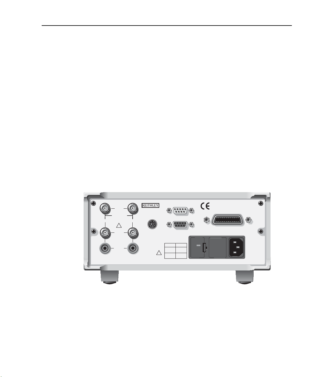
Model 2500 and 2502 User’s Manual Getting Started 1-9
WARNING:NO INTERNAL OPERATOR SERVICABLE PARTS,SERVICE BY QUALIFIED PERSONNEL ONLY.
CAUTION:FOR CONTINUED PROTECTION AGAINST FIRE HAZARD,REPLACE FUSE WITH SAME TYPE AND RATING.
Power module:
Contains the AC line receptacle and the power line fuse.
Trigger link connector:
TRIGGER LINK 8-pin micro-DIN connector for sending and receiving trigger pulses.
Use a trigger link cable or adapter, such as Models 8501-1, 8501-2,
8502, 8504.
RS-232 connector:
RS-232 Connector for RS-232 remote operation. Use a straight through (not
null modem) DB-9 cable such as a Keithley Model 7009-5.
GPIB connector:
IEEE-488 INTERFACE Connector for GPIB remote operation. Use a shielded cable
(Model 7007-1 or 7007-2).
ANALOG OUT connectors (Model 2502 only):
ANALOG OUT Triax connectors for CHANNEL 1 and CHANNEL 2 analog outputs.
Figure 1-3
Model 2502 rear panel
INPUT
RATINGS MAX.
100V @ 20mA
COMMON
MODE
CHANNEL 1
200V
!
CAT I
ANALOG
OUT
VOLTAGE
SOURCE
OUT
CHANNEL 2
MADE IN
U.S.A.
TRIGGER LINK
DIGITAL I/O
RS-232
LINE RATING
50, 60Hz
60 VA MAX
FUSE LINE
630 mAT
100 VAC
(SB)
315 mAT
(SB)
120 VAC
220 VAC
240 VAC
!
Model 2502
120
IEEE-488
(CHANGE IEEE ADDRESS
WITH FRONT PANEL MENU)
Page 42

1-10 Getting Started Model 2500 and 2502 User’s Manual
Power-up
Line voltage selection
The Model 2500 operates from a line voltage in the range of 100V/120V/220V/240V,
±10% at a frequency of 50 or 60Hz. Before plugging in the unit make sure the line voltage
setting seen through the small window in the power module (Figure 1-2) is correct for the
line voltage in your area.
CAUTION Operating the instrument on an incorrect line voltage may cause dam-
age, possibly voiding the warranty.
If the voltage setting is not correct, change it as outlined below.
WARNING Disconnect the line cord and all cables and test leads from the instru-
ment before changing the line voltage setting.
1. Pry the small tab that secures the fuse holder to the power module, then remove the
fuse holder.
2. Pull out and rotate the fuse carrier to the correct line voltage setting, then install it in
the fuse holder. Make sure the line voltage shown in the window is correct. Also make
sure the fuse rating for the expected line voltage is correct. (See “Fuse replacement.”)
3. Reinstall the fuse holder in the power module making sure it is seated fully.
Line power connection
Perform the following steps to connect the Model 2500 to line power and turn it on:
1. Before plugging in the power cord make sure the front panel power switch is in the off
(0) position.
2. Connect the female end of the supplied power cord to the AC receptacle on the rear
panel.
WARNING The power cord supplied with the Model 2500 contains a separate
ground for use with grounded outlets. When proper connections are
made, instrument chassis is connected to power line ground through
the ground wire in the power cord. Failure to use a grounded outlet
may result in personal injury or death due to electric shock.
3. Turn on the instrument by pressing the front panel power switch to the on (1) position.
Page 43

Model 2500 and 2502 User’s Manual Getting Started 1-11
Power-up sequence
On power-up, the Model 2500 performs self-tests on its EPROM and RAM and
momentarily lights all segments and annunciators. If a failure is detected, the instrument
momentarily displays an error message, and the ERR annunciator turns on. Error
messages are listed in Appendix B.
NOTE If a problem develops while the instrument is under warranty, return it to
Keithley Instruments, Inc., for repair.
If the instrument passes the self-tests, the firmware revision levels are displayed. For
example:
REV A01 A02
where: A01 is the main board ROM revision.
A02 is the display board ROM revision.
Also displayed is the line frequency (50 or 60Hz). (If the wrong frequency is displayed, it
can be manually set as covered below). The communication interface status is briefly displayed. If the IEEE-488 bus is the presently selected interface, the identification message
will include the primary address. For example, if the primary address is 25 (factory
default), the IEEE Addr=25 message is displayed. If the RS-232 interface is selected, the
RS-232 message is displayed.
After the power-up sequence, the instrument goes to its normal display state with the output off (red ON/OFF OUTPUT indicator light off).
System identification
To obtain the serial number and revision information, use the MENU/GENERAL/
SERIAL # selection or the *IDN? query via remote.
Page 44

1-12 Getting Started Model 2500 and 2502 User’s Manual
Line frequency setting
If the line frequency setting (50 or 60Hz) does not match the power line frequency in your
area, noisy measurement readings will result, and accuracy may be affected. You can manually set the line frequency from the front panel or via remote as covered below.
Front panel line frequency
Set the line frequency from the front panel as follows:
1. Press the MENU key to display MAIN MENU.
2. Using the right arrow key, select AD-CTRL then press ENTER to display A/D
CONTROLS.
3. Select LINE-FREQUENCY, then press ENTER to display LINE FREQUENCY.
4. Place the cursor on 50Hz or 60Hz, and press ENTER.
5. Press EXIT to return to normal display.
Remote command line frequency
Use the following command to set the line frequency:
:SYSTem:LFRequency <Freq>
See Section 17 for additional information on using this command.
Programming example
50Hz operation:
:SYST:LFR 50
Fuse replacement
A rear panel fuse protects the power line input of the Model 2500. If the line fuse needs to
be replaced, perform the steps below:
WARNING Disconnect the line cord and all cables and test leads from the instru-
1. The fuse is located in a holder in the power module adjacent to the AC receptacle
(Figure 1-2). At the right of the fuse holder is a small tab. At this location, use a small
bladed screwdriver to release the fuse holder.
2. Slide the fuse holder out to gain access to the fuse carrier and fuse.
ment before changing the line fuse.
Page 45

Model 2500 and 2502 User’s Manual Getting Started 1-13
3. Remove the carrier with blown fuse, and replace the fuse with the correct type listed in
Table 1-1.
CAUTION For continued protection against fire or instrument damage, replace
the fuse only with the type and rating listed. If the instrument repeatedly blows fuses, locate and correct the cause of the problem before
replacing the fuse.
4. Install the fuse carrier in the fuse holder then insert the fuse holder in the power
module.
Table 1-1
Line fuses
Line voltage Fuse rating Keithley part no.
Display
Display format
100V, 120V
220V, 240V
The Model 2500 display is used primarily to display measured readings and voltage bias
source values. The top line displays measurement function readings, and the bottom line
shows voltage bias values. Channel 1 measurement function readings (MSR1) are displayed on the left, while channel 2 measurement function values (MSR2) appear on the
right. (You can select channel 1, channel 2, or dual-channel display with the CHANNEL
SELECT and DISPLAY TOGGLE keys; see “CHANNEL SELECT key” and “DISPLAY
TOGGLE key” below.)
Measurement reading information can be displayed using either engineering units or scientific notation in either fixed- or floating-point format. Use the GENERAL/NUMBERS
selection of the main MENU to select the display format, as discussed under “Menus”
later in this section.
Engineering units example: 1.234567µA
Scientific notation example: 1.234567e -6A
0.630A slow blow, 250V, 5 × 20mm
0.315A slow blow, 250V, 5 × 20mm
FU-106-.630
FU-106-.315
Annunciators, which are located along the top of the reading/message display, indicate
various states of operation as covered previously in “Front panel summary.”
Page 46

1-14 Getting Started Model 2500 and 2502 User’s Manual
CHANNEL SELECT key
The CHANNEL SELECT key toggles between the channel 1 and channel 2 measurements
on the left-hand display when the single-channel display mode is selected (see below).
DISPLAY TOGGLE key
The DISPLAY TOGGLE key turns the dual-channel display mode on or off. When the
dual-channel mode is active, the channel 1 measurement function reading (MSR1) appears
on the left (I, V/I, I/V, I × V, or MX + B), while the channel 2 measurement function
(MSR2) appears on the right of the top line. The DISPLAY TOGGLE key is also used to
select the channel and display statistical data on readings stored in the data store buffer.
These functions are performed from the data store RECALL mode. (See Section 8 for data
store information.)
Status and error messages
Status and error messages are displayed momentarily. During Model 2500 operation and
programming, you will encounter a number of front panel messages. Typical messages are
either status or error in nature and are listed in Appendix B.
Disabling front panel display
Front panel display circuitry can be disabled to allow the instrument to operate at a higher
speed. While disabled, the display is frozen with the following message:
FRONT PANEL DISABLED
Press LOCAL to resume.
As reported by the message, all front panel controls (except LOCAL, TRIG, and OUTPUT ON/OFF) are disabled.
Front panel control
Front panel display circuitry is controlled from the DISABLE DISPLAY configuration
menu, which is accessed by pressing CONFIG and then CHANNEL SELECT or DISPLAY TOGGLE. To select an option (NOW, NEVER, SWEEP, or STORE), use the and
keys to place the cursor on the desired option, then press ENTER.
The options for DISABLE DISPLAY are explained as follows:
NOW — Select this option to disable the display now.
NEVER — Select this option if you do not want the display to disable.
Page 47

Model 2500 and 2502 User’s Manual Getting Started 1-15
SWEEP — Select this option if you want the display to disable while performing a sweep.
The display will disable as soon as sweep is started. The display will automatically reenable after the sweep is completed.
STORE — Select this option if you want the display to disable when storing sourcemeasure readings in the buffer. The display will disable as soon as the buffer is enabled.
The display will automatically re-enable after the storage process is completed. Note that
with this option, the display will disable while performing a sweep. Sweep readings are
automatically stored in the buffer.
Remote display programming
The display can be controlled by various SCPI :DISPlay subsystem commands. Table 1-2
summarizes basic commands. See Section 17, “DISPlay subsystem,” for more information
on using these commands.
Table 1-2
Basic display commands
Command Description
:DISPplay:ENABle <state>
:DISPlay:DIGits <n>
:DISPlay:MODE<name>
Front panel tests
Use the TEST/DISPLAY TESTS selection of the main MENU to test various aspects of
the front panel. Test selections include:
• KEYS — Front panel keys are tested. Pressing a key displays a message that identifies
that key. Pressing EXIT twice cancels this test.
• DISPLAY PATTERNS — Use this selection to turn on all display pixels and annun-
ciators. Subsequent key presses cycle through tests that turn off annunciators and corner pixels of each digit, turn on the rows of the top-left display digit, and turn on all
annunciators and pixels of each digit in a sequential manner. Press EXIT to cancel this
test.
• CHAR SET — This test displays special characters. Press EXIT to cancel the test.
See “Menus,” page 1-20, for more menu information.
Enable/disable display (state = ON or OFF).
Set display resolution (n = 3 to 6).
Select display mode (name = CALC3,
CALC4, CALC5, CALC6, or DUAL).
Page 48

1-16 Getting Started Model 2500 and 2502 User’s Manual
Default settings
By using appropriate menu selections, you can save and recall various instrument setups,
define the power-on configuration, or restore factory defaults as outlined below.
Saving and restoring user setups
You can save and restore up to five of your own user setups using the following
procedures.
Saving setups
1. Select the various instrument operating modes you wish to save.
2. Press the MENU key, select SAVESETUP, then press ENTER.
3. From the SAVESETUP MENU, select SAVE, then press ENTER.
4. Select the setup position (0-4) to save, then press ENTER to complete the process.
Restoring setups
1. Press the MENU key, select SAVESETUP, then press ENTER.
2. From the SAVESETUP MENU, select RESTORE, then press ENTER.
3. Select the setup position (0-4) to restore, then press ENTER to complete the process.
Power-on configuration
You can also define which of the stored setups (factory default or user) the instrument
assumes as the power-on configuration as follows:
1. Press the MENU key, select SAVESETUP, then press ENTER.
2. From the SAVESETUP MENU, select POWERON, then press ENTER.
3. From the SET POWER-ON DEFAULT menu, choose the power-on configuration:
BENCH or GPIB (see below), or USER-SETUP-NUMBER.
4. If you chose to use a user setup as the power-on configuration, select the user setup
number, then press ENTER.
Factory default settings
As summarized in Table 1-3, there are two sets of factory defaults, BENCH (front panel)
and GPIB (remote). You can restore either of these default conditions as follows:
1. Press the MENU key, select SAVESETUP, then press ENTER.
2. From the GLOBAL SETUP MENU, select RESET, then press ENTER.
3. Select BENCH or GPIB defaults as desired, then press ENTER to complete the
process.
Page 49

Model 2500 and 2502 User’s Manual Getting Started 1-17
Table 1-3
Factory default settings
Setting* BENCH default GPIB default
A/D Controls:
Auto-zero
Line frequency
Data Store
Digital output size**
Display digits
Display mode
Filter:
Average mode, state*
Average filter count*
Advanced state, tol. *
Median filter rank, state*
GPIB address
Ground connect
On
No effect
No effect
15 or 7
5.5
Dual-channel
Off
Repeat, disabled
10
Off, 5%
0, Off
No effect
Disabled
On
No effect
No effect
15 or 7
5.5
Dual-channel
Off
Repeat, disabled
10
Off, 5%
0, Off
No effect
Disabled
Limit tests:
DigOut:
Size
Mode:
Binning control
Auto clear:
Delay
Clear pattern**
4-bit
Grading
Immediate
Disabled
0.00001 sec
15 or 7
4-bit
Grading
Immediate
Disabled
0.00001 sec
15 or 7
H/W limits (1 and 2):
Control
Fail mode:
Digital I/O pattern*
Disabled
In compliance
15 or 7
Disabled
In compliance
15 or 7
S/W limits (3 to 6):
Control
Low limit:
Low pattern**
High limit:
High pattern**
Feed
Pass pattern**
EOT Mode
Math function and units:
M factor (gain)
B factor (slope)
State
* Settings are for both channel 1 and channel 2.
** 15 if digout size is 4-bit, 7 if digout size is 3-bit.
Disabled
-1.0
15 or 7
+1.0
15 or 7
Channel 1 measure
15 or 7
EOT
MX +B, MXB
1
0
Disabled
Disabled
-1.0
15 or 7
+1.0
15 or 7
Channel 1 measure
15 or 7
EOT
MX + B, MXB
1
0
Disabled
Page 50

1-18 Getting Started Model 2500 and 2502 User’s Manual
Table 1-3 (continued)
Factory default settings
Setting BENCH default GPIB default
Numbers
No effect
No effect
Optical power:
R
D
Output:
Output enable
Power-on default
1
0
Off
Disabled
No effect
1
0
Off
Disabled
No effect
Ranging (measure):
Auto range
Upper limit
Lower limit
Rel:
Value
RS-232
Source delay:
Auto-delay
Speed
Sweep:
Start
Stop
Step
Direction
Sweep count
Sweep points
Source ranging
Enabled
20mA
2nA
Off
0.0
No effect
1ms
Enabled
1 PLC
None
0V
0V
0V
Up
1
3000
Best fixed
Enabled
20mA
2nA
Off
0.0
No effect
1ms
Enabled
1 PLC
None
0V
0V
0V
Up
1
3000
Best fixed
Triggered source:
Control
Amplitude
Disabled
0
Disabled
0
Page 51

Model 2500 and 2502 User’s Manual Getting Started 1-19
Table 1-3 (continued)
Factory default settings
Setting BENCH default GPIB default
Triggering:
Arm layer:
Event
Count
Timer
Input line
Output trigger
Trigger layer:
Event
Count
Timer
Input line
Output triggers
Delay
Voltage bias sources:
Amplitude
Range
Mode
Immediate
1
0.1
1
Line #2, Off
Immediate
1
0.1
1
Line #2, All off
0.0 sec
0V
10V
Fixed
Immediate
1
0.1
1
Line #2, Off
Immediate
1
0.1
1
Line #2, All off
0.0 sec
0V
10V
Fixed
Remote setups
You can also save and recall setups via remote using the following SCPI commands:
•Save and recall user setups using *SAV and *RCL (Section 15).
• Restore GPIB defaults using *RST (Section 15).
• Restore bench defaults using :SYSTem:PRESet (Section 17).
•Save the power-on configuration using :SYSTem:POSetup (Section 17).
Page 52

1-20 Getting Started Model 2500 and 2502 User’s Manual
Menus
The following paragraphs discuss the main menu, configuration menus, and rules to navigate menus.
Main menu
Use the MENU key to access the Main Menu to select, configure, and/or perform various
instrument operations. These include default setup conditions, communications (GPIB or
RS-232), calibration, front panel tests, digital output states, auto zero, timestamp, and
numeric display format.
The Main Menu structure is summarized in Table 1-4. Use the “Rules to navigate menus”
to check and/or change menu options. Figure 1-4 shows the main menu tree.
Table 1-4
Main menu
Menu item
SAVESETUP
SAVE
RESTORE
POWERON
BENCH
GPIB
USER-SETUP-NUMBER
RESET
COMMUNICATION
GPIB
RS-232
BAUD
BITS
PARITY
TERMINATOR
FLOW CTRL
1
Configure setup conditions.
Save present Model 2500 setup to memory location.
Return the Model 2500 to setup saved in memory.
Select the power-on default setup.
Powers-on to BENCH defaults.
Powers-on to GPIB defaults.
Powers-on to user setup.
2
Returns unit to BENCH or GPIB defaults.
Select and configure remote interface.
Select GPIB (IEEE-488 Bus), set primary address,
GPIB protocol (Appendix G).
Select the RS-232 interface, set parameters.
Select baud rate.
Select number of data bits.
Select parity.
Select terminator.
Select flow control.
Description Parameters
0 to 4
0 to 4
See Table 1-3.
See Table 1-3.
0 to 4
See Table 1-3.
0 to 30
(Default: 25)
57600, 38400,
19200, 9600,
4800, 2400,
1200, 600, 300
7 or 8
NONE, ODD,
EVEN
CR, CR+LF,
LF, or LF+CR
NONE or
XON/XOFF
Page 53

Model 2500 and 2502 User’s Manual Getting Started 1-21
Table 1-4 (continued)
Main menu
Menu item
3
CAL
TEST
DISPLAY-TESTS
KEYS
DISPLAY-PATTERNS
CHAR SET
A/D CTRL
AUTO-ZERO
DISABLE
ENABLE
LINE-FREQUENCY
GENERAL
DIGOUT
SERIAL#
TIMESTAMP
NUMBERS
1
Description Parameters
Calibrate Model 2500.
Perform tests on Model 2500.
4
Test front panel keys and display digits.
Test front panel keys.
Test display pixels and annunciators.
Test special display characters.
Control auto zero, line frequency, and NPLC caching.
5
Control auto zero.
Disable auto zero.
Enable auto zero.
Set the line frequency.
50 or 60Hz
Select general operations.
Set Digital I/O port bit pattern.
0-15
Display serial number, firmware revision, SCPI
version.
Reset timestamp.
Select engineering units or scientific notation display
YES or NO
ENGR,
SCIENTIFIC
format.
Notes:
1
Top level menu choices indicated in bold. Indentation identifies each lower submenu level.
2
When the remote operation interface selection (GPIB or RS-232) is changed, the Model 2500 performs a power-on reset. To check
or change options of the selected interface, you must re-enter the menu structure.
3
Password is required to unlock calibration. (See Service Manual.)
4
Press EXIT key to cancel test.
5
Disabling auto zero will reduce measurement accuracy.
Page 54

1-22 Getting Started Model 2500 and 2502 User’s Manual
Figure 1-4
Main menu tree
Press MENU key (Use and to select item, then press ENTER)
SAVESETUP
SAVE
RESTORE
POWERON
BENCH
GPIB
USER-SETUP-NUMBER
RESET
COMMUNICATION
GPIB
RS-232
CAL
UNLOCK
EXECUTE
VIEW-DATES
SAVE
LOCK
CHANGE-PASSWORD
TEST
DISPLAY-TESTS
A/D CTRL
AUTO-ZERO
LINE-FREQUENCY
▲
▲
BAUD
BITS
PARITY
TERMINATOR
FLOW-CTRL
KEYS
DISPLAY-PATTERNS
CHAR-SET
GENERAL
DIGOUT
SERIAL#
TIMESTAMP
NUMBERS
Page 55

Model 2500 and 2502 User’s Manual Getting Started 1-23
Rules to navigate menus
Many functions and operations are configured from the front panel menus. Use the following rules to navigate through these configuration menus:
•A menu item is selected by placing the cursor on it and pressing ENTER. Cursor position is denoted by the blinking menu item or option. The edit left and right arrow keys
control cursor position.
•A displayed arrow on the bottom line indicates there are one or more additional items
(or messages) to select from. Use the appropriate cursor key to display them.
•A measurement or voltage bias source range is changed by selecting the channel and
function with the MSR1, MSR2, SRC1, or SRC2 key and using the RANGE or
keys. Note that when the next higher or lower range is selected, the reading increases
or decreases by a decade.
•A parameter value is keyed in by placing the cursor on the digit to be changed and
using one of the following methods:
NOTE You can clear a parameter value by pressing the 0000 (MENU) key.
• Use the EDIT or or RANGE or keys to increment or decrement the digit.
• Use the number keys (0 through 9) to key in the value at the selected digit.
• Use the ± key to change source value polarity, regardless of cursor position.
• Boolean selections (such as ON/OFF and HIGH/LOW) are toggled by placing the cursor on the selection and pressing an EDIT or or RANGE or key.
•A change is only executed when ENTER is pressed. Entering an invalid parameter
generates an error, and the entry is ignored. However, entering an out-of-range value
(too small or too large) selects the lower or upper limit, respectively.
• The EXIT key is used to back out of the menu structure. Any change that is not entered
is cancelled when EXIT is pressed.
Page 56

1-24 Getting Started Model 2500 and 2502 User’s Manual
Editing voltage bias values
Use the following keys to edit voltage bias values:
• SRC1 or SRC2: selects the channel 1 (Src1) or channel 2 (Src2) source display field on
the lower line for editing. A blinking cursor will appear in the field to be edited. If no
key is pressed within a few seconds, the edit mode will be cancelled automatically.
• EDIT and places the display cursor on the display digit to be changed.
• EDIT or increments or decrements the source value. Note that pressing either of
these keys will automatically enable the source edit mode.
• RANGE or selects the voltage bias source range (10V or 100V).
• Numeric keys (0-9) allow you to directly enter source values.
• EXIT exits the edit mode without waiting for the time-out period.
The basic procedure for editing source values is outlined below. See Section 3, “Basic
measurement procedure,” for more details.
1. Press the SRC1 or SRC2 key so the blinking cursor is in either the channel 1 (Src1) or
channel 2 (Src2) source display field to be edited.
2. If desired, use the RANGE and keys to select the desired source range. (Use the
lowest range possible for best accuracy.)
3. To simply increment or decrement the displayed source value, use the EDIT and
keys to place the blinking cursor on the digit to be changed, then increment or decrement the value with the EDIT and keys. Note that the source value will be updated
immediately; you need not press ENTER to complete the process.
4. To enter the source value directly, simply key in the desired value with the numeric
keys while the cursor is blinking. Again, the source value will be updated immediately.
Configuration menus
There are a number of configuration menus that can be accessed by pressing the CONFIG
key followed by the appropriate function or mode key. For example, you can configure the
measurement functions by pressing CONFIG then MSR1 (channel 1) or MSR2 (channel
2). Configuration menus, which are summarized in Table 1-5 through Table 1-11, are
available for the following operating modes:
• Measurement functions (MSR1, MSR2, RATIO, DELTA): Table 1-5.
•Voltage source (SRC1 and SRC2): Table 1-6.
• REL, FILTER, and RANGE: Table 1-7.
• LIMIT: Table 1-8.
• TRIG: Table 1-9.
• SWEEP, DIGITS, SPEED, and STORE: Table 1-10.
• ON/OFF OUTPUT and DISPLAY TOGGLE: Table 1-11.
Page 57

Model 2500 and 2502 User’s Manual Getting Started 1-25
These various configuration menus are covered in detail in the pertinent sections of this
manual.
Table 1-5
Measurement configuration menus
Configuration menu item Description
CONFIG MSR1
CONFIG MSR1 BUTTON
I
I/V
V/I
MX + B_UNIT
P
P→
CONFIG MSR2
CONFIG MSR2 BUTTON
I
I/V
V/I
MX + B_UNIT
P
P→
CONFIG RATIO
CONFIG RATIO BUTTON
MSR1/MSR2
MSR2/MSR1
CONFIG DELTA
CONFIG DELTA BUTTON
MSR1-MSR2
MSR2-MSR1
Configure channel 1 measurement.
Current measurement.
Conductance (I/V) measurement.
Resistance (V/I) measurement.
MX + B measurement, program M and B values.
Electrical power (V × I) measurement.
Optical power [(I
measured
– I
dark current
)/Responsivity].
Configure channel 2 measurement.
Current measurement.
Conductance (I/V) measurement.
Resistance (V/I) measurement.
MX + B measurement, program M and B values.
Electrical power (V × I) measurement.
Optical power [(I
measured
– I
dark current
)/Responsivity].
Configure ratio function.
MSR1/MSR2 function.
MSR2/MSR1 function.
Configure delta function.
MSR1-MSR2 function.
MSR2-MSR1 function.
Page 58

1-26 Getting Started Model 2500 and 2502 User’s Manual
Table 1-6
Source configuration menus
Configuration menu item Description
CONFIG SRC1
Configure delay and ground connect mode.
CONFIG SRC1
DELAY
AUTO-DELAY
DISABLE
ENABLE
GND-CONNECT
DISABLE
ENABLE
CONFIG SRC2
CONFIG SRC2
DELAY
AUTO-DELAY
DISABLE
ENABLE
GND-CONNECT
DISABLE
ENABLE
Set source delay (0 - 9999.998s).
Control source auto delay.
Disable auto delay.
Enable auto delay (delay depends on current range).
Control ground connect mode.
Disable ground connect mode.
Enable ground connect mode.
Configure delay and ground connect mode.
Configure voltage source.
Set source delay (0 - 9999.998s).
Control source auto delay.
Disable auto delay.
Enable auto delay (delay depends on current range).
Control ground connect mode.
Disable ground connect mode.
Enable ground connect mode.
Table 1-7
Rel, filter, and range configuration menus
Configuration menu item Description
CONFIG REL
CONFIG FILTER
CONFIGURE FILTERING
AVERAGE-MODE
MOVING
REPEAT
AVERAGE-COUNT
ADVANCED
DISABLE
ENABLE
MEDIAN-RANK
CONFIG
RANGE
CONFIG RANGE
Program REL value.
Configure filter.
Select average mode filter.
Moving average.
Repeat average.
Set average filter count (1-100).
Enable/disable advanced filter.
Disable advanced filter.
Enable advance filter, set noise tolerance.
Select median rank (0 -5).
Program upper range limit.
Program lower range limit.
Page 59

Model 2500 and 2502 User’s Manual Getting Started 1-27
Table 1-8
Limit configuration menu
Configuration menu item Description
CONFIG LIMIT
CONFIG LIMITS MENU
DIGOUT
SIZE
3-BIT
4-BIT
16-BIT (2499-DIGIO)
MODE
GRADING
IMMEDIATE
END
SORTING
AUTO-CLEAR
DISABLE
ENABLE
H/W-LIMITS
CONTROL
DISABLE
ENABLE
FAIL-MODE
IN
OUT
S/W-LIMITS
CONTROL
DISABLE
ENABLE
LOLIM
HILIM
PASS
FEED
PASS
DIGIO PATTERN
EOT-MODE
/BUSY
EOT
/EOT
Configure limit tests.
Program Digital I/O bit patterns for pass/fail.
Select I/O number of bits.
3-bit size.
4-bit size.
16-bit size (2499-DIGIO option only).
Select Digital I/O mode.
Pass if within HI/LO limits.
Stop test after first failure.
Stop test at end of sweep.
Fail if outside limits, program fail pattern.
Enable/disable auto clear.
Disable auto clear.
Enable auto clear, program pass/fail pattern.
Control and set fail mode for Limit 1, Limit 2 tests.
Control Limit 1 or 2 test.
Disable Limit 1 or 2 test.
Enable Limit 1 or 2 test.
Select Limit 1 or 2 fail mode.
Fail when in compliance, program bit pattern.
Fail when out of compliance, program bit pattern.
Control Limit 3 to Limit 6 tests.
Enable/disable Limit 3-6 tests.
Disable test.
Enable test.
Set low limit.
Set high limit.
Set pass Digital I/O bit pattern.
Select input path (MSR1, MSR2, RATIO, or DELTA).
Set limit test pass conditions.
Set pass conditions Digital I/O bit pattern.
Set Digital I/O line 4 to act as EOT or BUSY signal.
Set line 4 LO while unit is busy (3-bit mode).
Output line 4 HI pulse at end of test (3-bit mode).
Output line 4 LO pulse at end of test (3-bit mode).
Page 60

1-28 Getting Started Model 2500 and 2502 User’s Manual
Table 1-9
Trigger configuration menu
Configuration menu item Description
CONFIG TRIG
CONFIGURE TRIGGER
ARM LAYER
ARM-IN
IMMEDIATE
GPIB
TIMER
MANUAL
TLINK
ONCE
NEVER
↑STEST
ONCE
NEVER
↓STEST
ONCE
NEVER
↑↓STEST
ONCE
NEVER
ARM-OUT
LINE
EVENTS
TRIG-LAYER-DONE
COUNT
FINITE
INFINITE
TRIG LAYER
TRIGGER-IN
IMMEDIATE
TRIGGER-LINK
TRIGGER-OUT
LINE
EVENTS
DELAY
COUNT
HALT
Configure triggering.
Configure trigger model arm layer.
Select arm layer detection event.
Immediate event detection.
GPIB GET or *TRG.
After timer interval elapses, enter interval.
Front panel TRIG key.
Enter TLINK line and state.
Bypass event detection once.
Never bypass event detection.
When Digital I/O SOT line is pulsed high.
Bypass event detection once.
Never bypass event detection.
When Digital I/O SOT is pulsed low.
Bypass event detection once.
Never bypass event detection.
When Digital I/O SOT line is pulsed low or high.
Bypass event detection once.
Never bypass event detection.
Configure arm layer output trigger.
Select trigger link output line (1-4).
Enable/disable events.
Enable (ON) or disable (OFF) on exiting trigger layer.
Specify arm count.
Programmable count.
Never ending count.
Configure trigger layer of trigger model.
Select trigger layer detection event.
Trigger even occurs immediately.
Select trigger link line as event (1-4).
Configure trigger layer output trigger.
Select trigger link line (1-4).
Enable (ON) or disable (OFF).
Program trigger delay time.
Program trigger count.
Return unit to idle state.
Page 61

Model 2500 and 2502 User’s Manual Getting Started 1-29
Table 1-10
Sweep, digits, speed, and data store configuration menus
Configuration menu item Description
CONFIG SWEEP
CONFIGURE SWEEPS
TYPE
NONE
STAIR
LOG
CUSTOM
# POINTS
ADJUST-POINTS
INIT
SWEEP-COUNT
FINITE
INFINITE
SOURCE-RANGING
BEST-FIXED
AUTO-RANGE
FIXED
CONFIG DIGITS
DISPLAY DIGITS
CONFIG SPEED
SPEED-ACCURACY-MENU
FAST
MED
NORMAL
HI ACCURACY
OTHER
Configure sweeps.
Select sweep type.
Disable sweep.
Staircase sweep, program START, STOP, STEP.
Log sweep, program START, STOP, # POINTS.
Custom sweep, program parameters.
Program number of sweep points.
Set individual point values.
Set first point value.
Set sweep count.
Program sweep count value.
Never-ending sweep.
Set sweep ranging mode.
Best fixed range based on maximum value.
Auto range during sweep.
Set fixed source range.
Set display number of digits.
Select 3.5, 4.5, 5.5, or 6.5.
Set measurement speed.
Fast speed.
Medium speed.
Normal.
Maximum accuracy.
Program NPLCs (number power line cycles).
CONFIG STORE
STORE TIMESTAMP
ABSOLUTE
DELTA
Configure data store timestamp.
Absolute timestamp.
Delta timestamp.
Page 62

1-30 Getting Started Model 2500 and 2502 User’s Manual
Table 1-11
Output and display configuration menus
Configuration menu item Description
CONFIG ON/OFF OUTPUT
CONFIG OUTPUT
AUTO OFF
DISABLE
ENABLE
ALWAYS
AFTER-TRIG-COUNT
ENABLE
DISABLE
ENABLE
CONFIG DISPLAY TOGGLE
DISABLE DISPLAY
NOW
NEVER
SWEEP
STORE
Configure output.
Enable disable auto off mode.
Keep output on.
Turn output off after each measurement.
After each measurement.
When trigger count expires.
Enable/disable output enable.
Disable output enable.
Enable output enable.
Enable/disable display.
Disable display immediately.
Never disable display.
Turn display off during sweep.
Turn display off during buffer store.
Page 63

2
Connections
• Connection precautions — Summarizes precautions that should be observed when
making test connections to the Model 2500.
• INPUT and OUTPUT connectors — Shows the locations of the triax INPUT jacks
used for photodiode measurements and the OUTPUT jacks used to apply the voltage
bias to the photodiodes.
• Connector terminals — Details the terminal configuration of the triax INPUT connectors and the OUTPUT jacks.
• Output enable — Briefly covers the output enable circuit, which can be used to inhibit
the voltage sources with external switching.
• Photodiode connections — Provides detailed diagrams for connecting the
Model 2500 INPUT and OUTPUT connectors to the photodiodes in a laser diode test
system.
• Alternate connecting methods — Provides connecting diagrams for using the
Model 2500 as a stand-alone ammeter or stand-alone voltage source.
• Analog output connections (Model 2502 only) — Summarizes connections to the
analog outputs and gives equivalent circuits.
Page 64
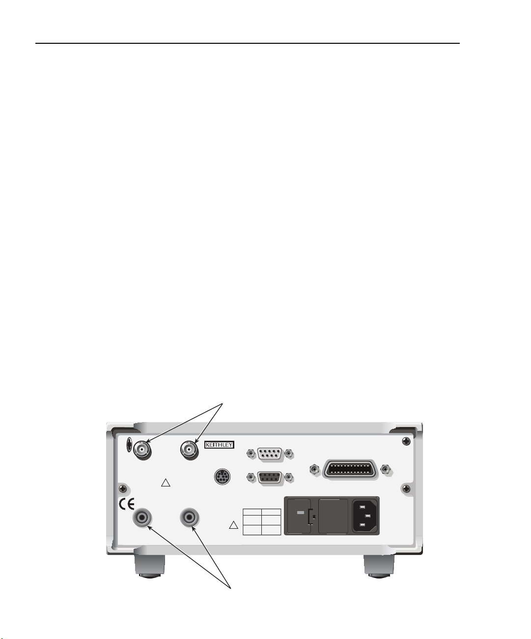
2-2 Connections Model 2500 and 2502 User’s Manual
WARNING: NO INTERNAL OPERATOR SERVICABLE PARTS, SERVICE BY QUALIFIED PERSONNEL ONLY.
CAUTION: FOR CONTINUED PROTECTION AGAINST FIRE HAZARD, REPLACE FUSE WITH SAME TYPE AND RATING.
Connection precautions
WARNING Maximum common-mode voltage (voltage between INPUT analog
common and chassis ground) is 200V. Exceeding this value may result
in a shock hazard.
When making connections, do not leave any exposed connections. Be
sure that all external circuits are properly insulated.
CAUTION Maximum INPUT and OUTPUT connector rating is 100V @ 20mA.
Exceeding these values may result in instrument damage.
INPUT and OUTPUT connectors
Figure 2-1 shows the location of the INPUT and OUTPUT connectors on the rear panel.
Each of these connectors has the following function:
• INPUT CHANNEL 1: A 3-lug triax connector for direct current input from the photodiode or other DUT to channel 1.
• INPUT CHANNEL 2: A 3-lug triax connector for direct current input from the photodiode or other DUT to channel 2.
•VOLTAGE SOURCE CHANNEL 1 OUTPUT: A safety banana jack used to apply the
channel 1 HI voltage bias source signal to the photodiode or other DUT.
•VOLTAGE SOURCE CHANNEL 2 OUTPUT: A safety banana jack used to apply the
channel 2 HI voltage bias source signal to the photodiode or other DUT.
Figure 2-1
Model 2500 rear panel showing INPUT and OUTPUT connectors
INPUT Connectors
RATINGS MAX
100V @ 20mA
COMMON
MODE
200V
INPUT
CHANNEL 1
VOLTAGE SOURCE
OUTPUT CHANNEL 1
!
CAT I
RATINGS MAX
100V @ 20mA
VOLTAGE SOURCE
OUTPUT CHANNEL 2
CHANNEL 2
MADE IN
INPUT
U.S.A.
TRIGGER LINK
!
Model 2500
OUTPUT Connectors
DIGITAL I/O
LINE RATING
50, 60Hz
60 VA MAX
FUSE LINE
630 mAT
(SB)
315 mAT
(SB)
RS-232
100 VAC
120 VAC
220 VAC
240 VAC
120
IEEE-488
(CHANGE IEEE ADDRESS
WITH FRONT PANEL MENU)
Page 65

Model 2500 and 2502 User’s Manual Connections 2-3
Connector terminals
Triax INPUT connectors
The electrical configuration of each triax INPUT connector is shown in Figure 2-2. Connector terminals are designated as follows:
• Center conductor of the connector (and triax cable): input HI. This terminal connects
to one terminal of the photodiode being tested.
• Inner ring of the connector and inner cable shield: input LO (analog common).
• Outer ring of connector (shell) and outer cable shield: chassis ground.
Figure 2-2
INPUT connector terminals
INPUT HI
INPUT LO
(Analog Common)
INPUT Triax Connector
OUTPUT connectors
Each channel has a single OUTPUT banana jack for the voltage bias source. Each connector is the HI terminal for the corresponding voltage source channel and connects to one
terminal of the photodiode being tested.
NOTE There ar e no separ ate e xternal connections for volta ge source LO. The LO node
of each voltage bias source is internally connected to floating analog common.
See “Photodiode connections” later in this section for connection details.
Chassis Ground
Page 66

2-4 Connections Model 2500 and 2502 User’s Manual
Output enable
An interlock switch can be used with the Model 2500 output enable line on the Digital I/O
Port to inhibit the voltage bias source outputs. When output enable is activated, the
Model 2500 outputs will turn off when the lid of the test fixture is opened. However, you
must ALWAYS assume that power is present until you verify that the Model 2500 output is
off.
WARNING To prevent electric shock, test connections must be configured such
that the user cannot come in contact with conductors or any DUT that
is in contact with the conductors. Safe installation requires proper
shields, barriers, and grounding to prevent contact with conductors.
Operator protection and safety are the responsibility of the person
installing the product.
See Section 12 for complete details on using the output enable circuit.
Photodiode connections
Typical connections
Figure 2-3 shows typical connections to the back detector and forward detector photo-
diodes in a laser diode test setup.
NOTE The DUT can be biased and measured using only a triax cable with the ground
connect mode. See “Ground connect mode connections,” page 2-7.
The two channels are being used as follows:
• Channel 1 biases and measures the current for the back detector photodiode. The center conductor of INPUT CHANNEL 1 HI is connected to photodiode terminal while
the VOLTAGE SOURCE CHANNEL 1 terminal is connected to the other photodiode
terminal.
• Channel 2 is used to bias and measure the forward detector photodiode. The center
conductor of INPUT CHANNEL 2 HI is connected to one photodiode terminal while
the VOLTAGE SOURCE CHANNEL 2 terminal is connected to the other photodiode
terminal.
See Section 4, “Photodiode Measurements,” for additional information on setting up
Model 2500 operating modes including making power measurements.
NOTE If an optional noise shield is used, connect the shield to INPUT LO (inner shield
of triax cable).
Page 67

Model 2500 and 2502 User’s Manual Connections 2-5
WARNING: NO INTERNAL OPERATOR SERVICABLE PARTS, SERVICE BY QUALIFIED PERSONNEL ONLY.
CAUTION: FOR CONTINUED PROTECTION AGAINST FIRE HAZARD, REPLACE FUSE WITH SAME TYPE AND RATING.
Figure 2-3
Typical photodiode connections
INPUT HI
Forward
Photodiode
Laser
Diode
Back
Photodiode
Optional Noise
Shield (Connect
to INPUT LO)
INPUT LO
INPUT HI
Triax Cables
INPUTS
RATINGS MAX
100V @ 20mA
COMMON
MODE
200V
INPUT
CHANNEL 1
!
CAT I
RATINGS MAX
100V @ 20mA
VOLTAGE SOURCE
OUTPUT CHANNEL 1
OUTPUTS
INPUT
CHANNEL 2
VOLTAGE SOURCE
OUTPUT CHANNEL 2
INPUT HI: center conductor
INPUT LO: inner shield
MADE IN
U.S.A.
TRIGGER LINK
!
DIGITAL I/O
LINE RATING
50, 60Hz
60 VA MAX
FUSE LINE
630 mAT
(SB)
315 mAT
(SB)
RS-232
100 VAC
120 VAC
220 VAC
240 VAC
120
Model 2500
IEEE-488
(CHANGE IEEE ADDRESS
WITH FRONT PANEL MENU)
Page 68

2-6 Connections Model 2500 and 2502 User’s Manual
Equivalent circuit
Figure 2-4 shows an equivalent circuit for the connection scheme shown in Figure 2-3.
The circuit includes two ammeters to make current measurements and two voltage sources
to bias the DUTs. Note that channel 1 and channel 2 analog common terminals are floating
and independent of one another.
Figure 2-4
Equivalent circuit of photodiode test connections
Back
Photodiode
Laser
Diode
Forward
Photodiode
I
INPUT HI
Channel 1
A
Channel 1
Analog
V-Source
OUTPUT
OUTPUT
V-Source
A
INPUT HI
Common
Channel 2
Channel 2
Analog
Common
I
Connection considerations
To avoid noise and offset currents that could degrade measurement accuracy, be sure to
use only quality, low-noise triax cables for INPUT connections. Also keep cables and test
fixtures away from vibration and varying temperatures to minimize generated cable currents. See Appendix F, “Measurement Considerations,” for information on these and other
possible measurement problems and how to avoid them.
Model 2500
Page 69
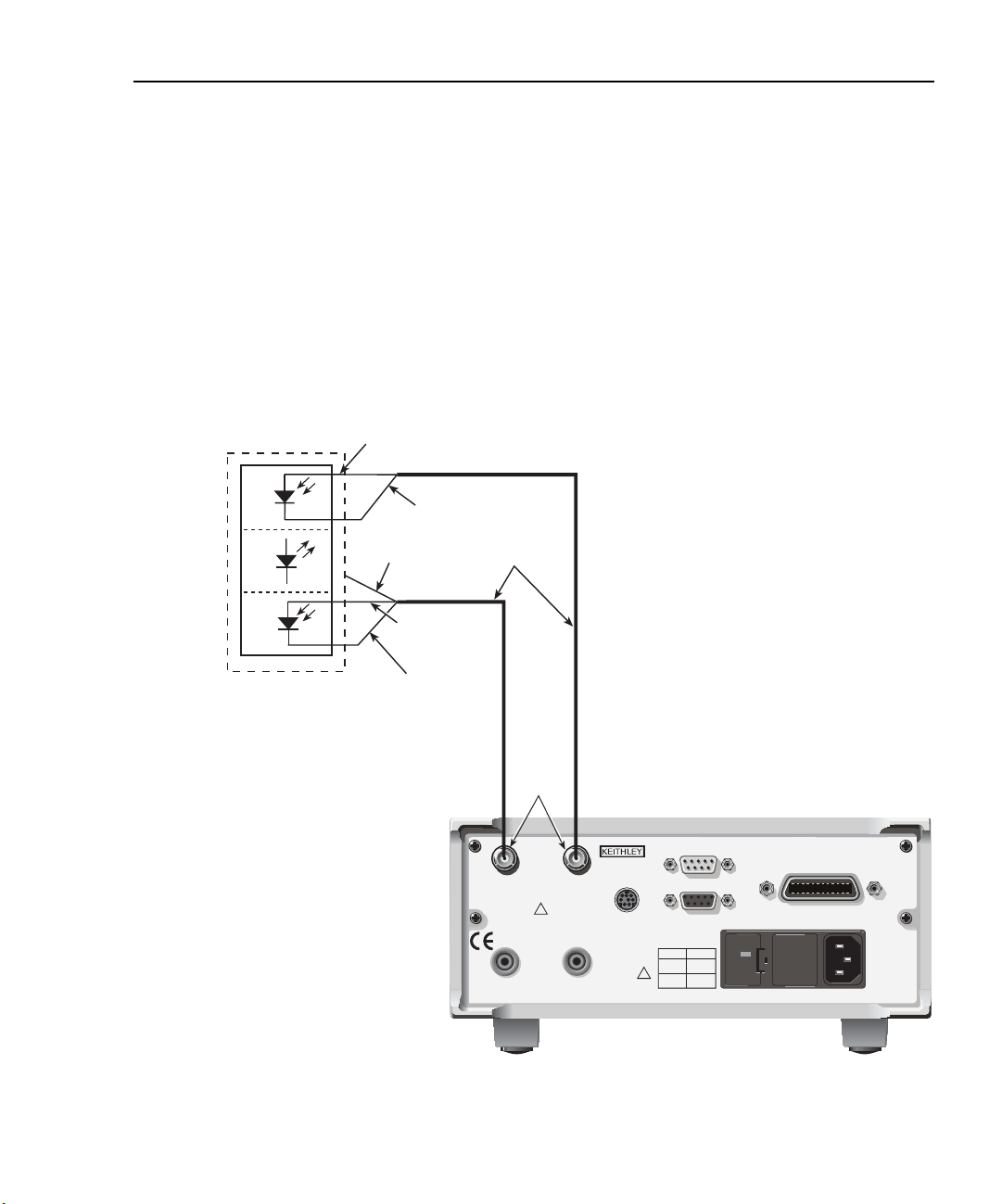
Model 2500 and 2502 User’s Manual Connections 2-7
WARNING: NO INTERNAL OPERATOR SERVICABLE PARTS, SERVICE BY QUALIFIED PERSONNEL ONLY.
CAUTION: FOR CONTINUED PROTECTION AGAINST FIRE HAZARD, REPLACE FUSE WITH SAME TYPE AND RATING.
Ground connect mode connections
The VOLTAGE SOURCE output jack for either channel can either be connected to chassis
ground or left floating, depending on the selected ground connect mode. (See Section 3,
“Ground connect mode,” for details.) With ground connect disabled, you must make sepa-
rate connections to the VOLTAGE SOURCE OUTPUT jack, as shown in Figure 2-3.
However, with ground connect enabled, you can bias and measure the DUT using a single
triax cable, as shown in Figure 2-5. Note that one DUT terminal is connected to INPUT
HI, while the other DUT terminal is connected to chassis ground through the outer shield
of the triax cable connection. Figure 2-6 shows an equivalent circuit.
Figure 2-5
Test connections using ground connect mode
INPUT HI
Forward
Photodiode
Chassis Ground
Laser
Diode
Back
Photodiode
Optional Noise
Shield (Connect
to INPUT LO)
INPUT LO
INPUT HI
Chassis Ground
Triax Cables
INPUTS
RATINGS MAX
100V @ 20mA
COMMON
MODE
200V
INPUT
CHANNEL 1
!
CAT
RATINGS MAX
100V @ 20mA
VOLTAGE SOURCE
OUTPUT CHANNEL 1
INPUT
CHANNEL 2
I
VOLTAGE SOURCE
OUTPUT CHANNEL 2
INPUT HI: center conductor
INPUT LO: inner shield
Chassis Ground: outer shield
MADE IN
U.S.A.
TRIGGER LINK
!
DIGITAL I/O
LINE RATING
50, 60Hz
60 VA MAX
FUSE LINE
630 mAT
(SB)
315 mAT
(SB)
RS-232
100 VAC
120 VAC
220 VAC
240 VAC
120
Model 2500
IEEE-488
(CHANGE IEEE ADDRESS
WITH FRONT PANEL MENU)
Page 70

2-8 Connections Model 2500 and 2502 User’s Manual
Figure 2-6
Ground connect mode equivalent circuit
Back
Photodiode
Laser
Diode
Forward
Photodiode
I
INPUT HI
Channel 1
A
Channel 1
Analog
V-Source
INPUT
Outer Shield
Chassis Ground
Chassis Ground
INPUT
Outer Shield
V-Source
A
INPUT HI
Common
Channel 2
Channel 2
Analog
Common
I
Model 2500
Page 71
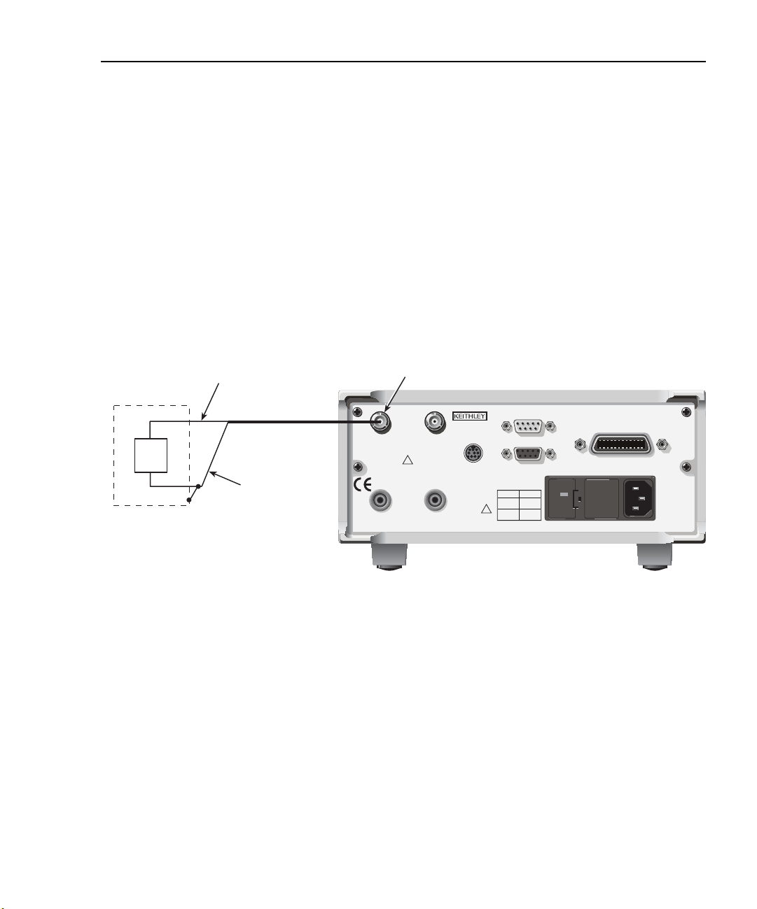
Model 2500 and 2502 User’s Manual Connections 2-9
WARNING: NO INTERNAL OPERATOR SERVICABLE PARTS, SERVICE BY QUALIFIED PERSONNEL ONLY.
CAUTION: FOR CONTINUED PROTECTION AGAINST FIRE HAZARD, REPLACE FUSE WITH SAME TYPE AND RATING.
Alternate connecting methods
Although the Model 2500 is designed primarily to bias and measure photodiodes in a laser
diode test system, it can also be used for stand-alone current measurements, or as a standalone voltage source with any suitable device.
Current measurement connections
Figure 2-7 shows typical connections using channel 1 to measure the DUT current. Note
that the INPUT HI terminal (center conductor) is connected to DUT HI, while the INPUT
LO terminal (analog common) is connected to DUT LO.
Figure 2-7
Stand-alone current measurement connections
INPUT HI
(Center Conductor)
DUT
Optional Noise Shield
(Connect to INPUT LO)
Triax Cable
INPUT LO
(Inner Shield)
Channel 1 INPUT
RATINGS MAX
100V @ 20mA
COMMON
MODE
200V
INPUT
CHANNEL 1
VOLTAGE SOURCE
OUTPUT CHANNEL 1
!
CAT I
RATINGS MAX
100V @ 20mA
VOLTAGE SOURCE
OUTPUT CHANNEL 2
INPUT
CHANNEL 2
MADE IN
U.S.A.
TRIGGER LINK
DIGITAL I/O
RS-232
LINE RATING
50, 60Hz
60 VA MAX
FUSE LINE
630 mAT
100 VAC
(SB)
120 VAC
!
315 mAT
220 VAC
(SB)
240 VAC
Model 2500
120
IEEE-488
(CHANGE IEEE ADDRESS
WITH FRONT PANEL MENU)
Page 72
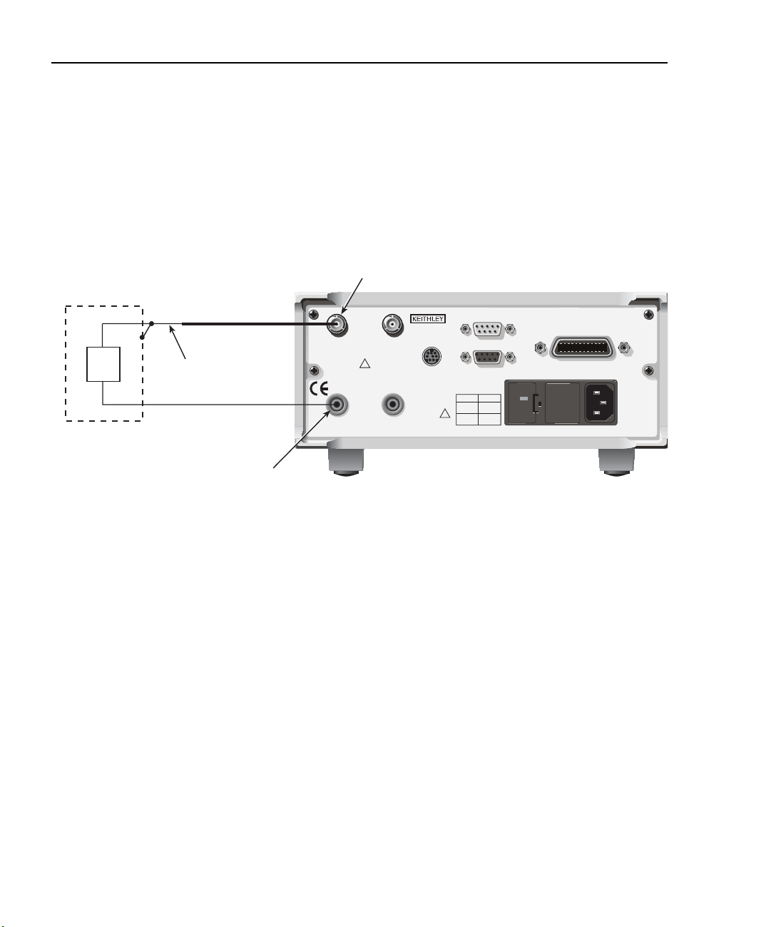
2-10 Connections Model 2500 and 2502 User’s Manual
WARNING: NO INTERNAL OPERATOR SERVICABLE PARTS, SERVICE BY QUALIFIED PERSONNEL ONLY.
CAUTION: FOR CONTINUED PROTECTION AGAINST FIRE HAZARD, REPLACE FUSE WITH SAME TYPE AND RATING.
Voltage source connections
Figure 2-8 shows the connecting scheme for using the Model 2500 as a stand-alone volt-
age source. Note that the DUT HI terminal is connect to the OUTPUT terminal for the
voltage source, while the DUT LO terminal is connected to analog common (inner ring of
INPUT jack). The maximum voltage source output is 100V @ 20mA.
Figure 2-8
Stand-alone voltage source connections
Channel 1 INPUT
LO
DUT
INPUT LO
(Inner Shield)
HI
Optional Noise Shield
(Connect to INPUT LO)
Triax Cable
Channel 1 OUTPUT
RATINGS MAX
100V @ 20mA
INPUT
CHANNEL 1
RATINGS MAX
100V @ 20mA
VOLTAGE SOURCE
OUTPUT CHANNEL 1
COMMON
MODE
200V
!
CAT I
VOLTAGE SOURCE
OUTPUT CHANNEL 2
INPUT
CHANNEL 2
MADE IN
U.S.A.
TRIGGER LINK
DIGITAL I/O
RS-232
LINE RATING
50, 60Hz
60 VA MAX
FUSE LINE
630 mAT
100 VAC
(SB)
120 VAC
!
315 mAT
220 VAC
(SB)
240 VAC
Model 2500
120
IEEE-488
(CHANGE IEEE ADDRESS
WITH FRONT PANEL MENU)
Page 73

Model 2500 and 2502 User’s Manual Connections 2-11
Analog output connections (Model 2502 only)
Analog output connector terminals
Figure 2-9 shows the terminal configuration of each triax ANALOG OUT connector.
Output terminals are as follows:
• Center conductor: analog output HI
• Inner shield: analog output LO (floating analog common)
• Outer shield: chassis ground
WARNING Analog output low can float up to ±100V. Use care to avoid a shock
hazard when using the analog outputs.
Figure 2-9
Analog output connector terminals
Analog Output HI
Analog Output LO
(Analog Common)
ANALOG OUT
Triax Connector
Chassis Ground
Page 74

2-12 Connections Model 2500 and 2502 User’s Manual
WARNING:NO INTERNAL OPERATOR SERVICABLE PARTS,SERVICE BY QUALIFIED PERSONNEL ONLY.
CAUTION:FOR CONTINUED PROTECTION AGAINST FIRE HAZARD,REPLACE FUSE WITH SAME TYPE AND RATING.
Non-isolated connections
Figure 2-10 shows typical non-isolated analog output connections. Note that analog
output HI (center conductor) is connected to INPUT HI of the measurement instrument,
while analog output LO (inner shield) is connected to INPUT LO.
CAUTION With the ground connect mode enabled, analog output LO can float up
to ±100V above chassis ground, depending on the voltage bias source
setting. Connecting the analog outputs to external equipment that does
not allow analog output low to float up to ±100V may result in damage
to the Model 2502 voltage bias sources when the ground connect mode
is enabled.
Figure 2-10
Non-isolated analog output connections
Measuring Instrument
PREV
DCV ACV DCI ACI Ω2 Ω4
DISPLAY
NEXT
REL TRIG
POWER
STORE RECALL
INFO LOCAL EXIT ENTER
CHAN SCAN
FILTER MATH
CONFIG MENU
2001 MULTIMETER
FREQ TEMP
RANGE
AUTO
RANGE
INPUT
SENSE
Ω 4 WIRE
350V
PEAK
INPUTS
FR
FRONT/REAR
CAL
LO
INPUT
HI
INPUT
HI
1100V
!
PEAK
LO
500V
PEAK
2A 250V
AMPS
Center
Conductor
Triax
Cable
Inner
Shield
CHANNEL 1
CHANNEL 1
ANALOG
OUT
INPUT
RATINGS MAX.
100V @ 20mA
COMMON
MODE
200V
!
CAT I
ANALOG
OUT
VOLTAGE
SOURCE
OUT
Model 2502
MADE IN
U.S.A.
CHANNEL 2
TRIGGER LINK
IEEE-488
(CHANGE IEEE ADDRESS
DIGITAL I/O
RS-232
LINE RATING
50, 60Hz
60 VA MAX
FUSE LINE
630 mAT
100 VAC
(SB)
120 VAC
!
315 mAT
220 VAC
(SB)
240 VAC
WITH FRONT PANEL MENU)
120
Page 75

Model 2500 and 2502 User’s Manual Connections 2-13
WARNING:NO INTERNAL OPERATOR SERVICABLE PARTS,SERVICE BY QUALIFIED PERSONNEL ONLY.
CAUTION:FOR CONTINUED PROTECTION AGAINST FIRE HAZARD,REPLACE FUSE WITH SAME TYPE AND RATING.
Isolated connections
To maintain proper isolation between the analog outputs and chassis ground, it is strongly
recommended that you use the isolated connections shown in Figure 2-11. In this case, an
Analog Devices 3B41-03 Isolated Wideband Voltage Input is used to provide isolation
between the Model 2502 ANALOG OUT and the measuring instrument. Analog output HI
(center conductor) is connected to the HI input terminal of the isolator and analog output
LO (inner shield) is connected to the LO input. The two isolator V
nected to the measuring instrument HI and LO INPUT terminals as shown.
Refer to the 3B41-03 documentation for connections, power supply, and configuration
information for your application.
Figure 2-11
Isolated analog output connections
INPUT
Measuring Instrument
PREV
DCV ACV DCI ACI Ω2 Ω4
DISPLAY
NEXT
REL TRIG
POWER
STORE RECALL
INFO LOCAL EXIT ENTER
CHAN SCAN
FILTER MATH
CONFIG MENU
2001 MULTIMETER
FREQ TEMP
SENSE
Ω 4 WIRE
HI
350V
!
PEAK
LO
INPUTS
FR
RANGE
AUTO
FRONT/REAR
RANGE
CAL
Analog Devices 3B41-03
Wideband Isolated
Voltage Input
HI
INPUT
VOUT
VOUT
1100V
PEAK
Common
500V
PEAK
2A 250V
AMPS
HI
Input
LO
Center
Conductor
Triax
Cable
Inner
Shield
CHANNEL 1
INPUT
RATINGS MAX.
100V @ 20mA
COMMON
MODE
CAT I
ANALOG
VOLTAGE
SOURCE
CHANNEL 2
200V
!
TRIGGER LINK
OUT
OUT
terminals are con-
OUT
Model 2502
MADE IN
U.S.A.
DIGITAL I/O
RS-232
LINE RATING
50, 60Hz
60 VA MAX
FUSE LINE
630 mAT
100 VAC
(SB)
120 VAC
!
315 mAT
220 VAC
(SB)
240 VAC
120
IEEE-488
(CHANGE IEEE ADDRESS
WITH FRONT PANEL MENU)
INPUT
LO
CHANNEL 1
ANALOG
OUT
Page 76
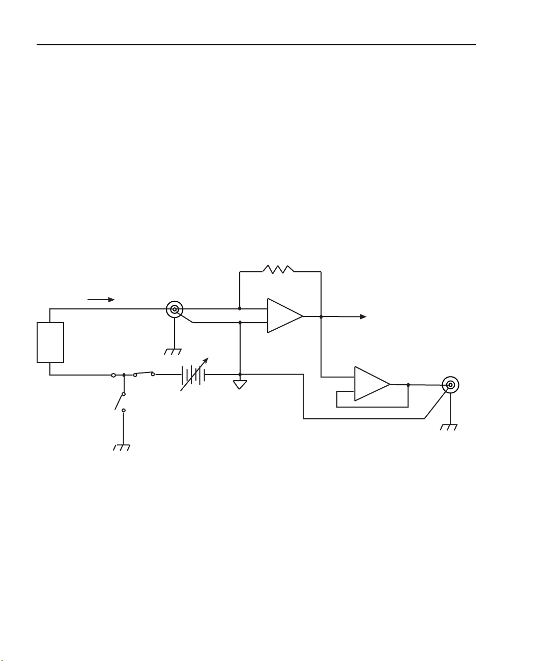
2-14 Connections Model 2500 and 2502 User’s Manual
Equivalent circuits
Figure 2-12 shows an equivalent circuit of the analog outputs with the ground connect
mode disabled. (Only one channel is shown; the other channel is identical.) Note that the
analog output circuit consists of a gain/buffer amplifier, and the analog output LO is connected to floating common.
Figure 2-13 shows an equivalent circuit with the ground connect mode enabled. In this
case, since one side of the voltage bias source is connected to chassis ground, analog
output LO can float up to ±100V above chassis ground depending on the voltage bias
source setting.
Figure 2-12
Analog output equivalent circuit with ground connect disabled
Feedback
R
F
Ammeter
Triax
INPUT
20mA Max
Chassis
Ground
Output
Enable
Chassis
Ground
HI
LO
Bias Source
0 to ±10V or
0 to ±100V
20mA Max
-
+
Floating channel 1
or channel 2
common
Note: One channel shown.
Other channel is identical.
To A/D
Converter
+
Amplifier
-
Buffer
ANALOG
OUT
HI
LO
Chassis
Ground
DUT
I
VOLTAGE
SOURCE
OUT
Ground
Connect
Disabled
Page 77

Model 2500 and 2502 User’s Manual Connections 2-15
Figure 2-13
Analog output equivalent circuit with ground connect enabled
Feedback
R
F
Ammeter
Triax
INPUT
20mA Max
Chassis
Ground
Output
Enable
Chassis
Ground
HI
LO
Bias Source
0 to ±10V or
0 to ±100V
20mA Max
-
To A/D
Converter
+
Floating channel 1
or channel 2
common
Note: One channel shown.
Other channel is identical.
+
-
Buffer
Amplifier
ANALOG
OUT
HI
LO
Chassis
Ground
DUT
I
VOLTAGE
SOURCE
OUT
Ground
Connect
Enabled
Page 78

3
Basic Operation
• Operation overview — Discusses current measurement and voltage bias source capabilities, ranges, compliance, and fundamental measurement and voltage bias circuit
configuration.
• Operation considerations — Covers warm-up, auto zero, and source delay.
• Basic measurement procedure — Describes the basic procedure for setting up the
Model 2500 for measurement and voltage bias operation, including choosing the measurement channel and range, selecting the source channel and setting output values,
and turning the output on and off.
• Using the analog outputs (Model 2502 only) — Covers basic characteristics of the
analog outputs.
Page 79

3-2 Basic Operation Models 2500 and 2502 User’s Manual
Operation overview
Measurement and voltage bias capabilities
The Model 2500 has the following measurement and voltage bias capabilities:
• Measure Current — Each Model 2500 channel can measure DC currents from ±1fA
to ±20mA. Each channel has eight current ranges: 2nA, 20nA, 200nA, 2µA, 20µA,
200µA, 2mA, and 20mA.
• Source Voltage — Each Model 2500 channel can output DC voltage from ±500µV to
±100V. Each channel has two ranges: 10V and 100V.
NOTE Both channel 1 and channel 2 are floating and independent of one another.
Ranges
Table 3-1 summarizes current measurement ranges, resolutions, and maximum readings
while Table 3-2 lists voltage bias source ranges, resolutions, and maximum voltage and
current. See Section 6 for more details on ranging.
Table 3-1
Current measurement ranges
Model 2500
I-range
2nA
20nA
200nA
2µA
20µA
200µA
2mA
20mA
Table 3-2
Voltage source ranges
Model 2500
V-range Resolution
10V
100V
Maximum
resolution
1fA
10fA
100fA
1pA
10pA
100pA
1nA
10nA
400µV
4mV
Maximum
±2.1nA
±21nA
±210nA
±2.1µA
±21µA
±210µA
±2.1mA
±21mA
Maximum
±10V
±100V
reading
voltage
Maximum
current
20mA
20mA
Page 80

Models 2500 and 2502 User’s Manual Basic Operation 3-3
Compliance
Each voltage bias source has a maximum output level of 100V @ 20mA. If the load resistance is low enough so that the unit exceeds the 20mA current limit, the unit is considered
to be in compliance, and the corresponding source display field (Src1 or Src2) will blink.
See Section 5, “Bias source operating boundaries,” for more information. You can also use
compliance for limit testing (Section 10), and the unit can be programmed to generate an
SRQ under compliance conditions over the GPIB (Section 14).
Basic circuit configuration
The fundamental circuit configuration for the Model 2500 is shown in Figure 3-1. Note
that the unit has two separate channels (one channel shown), each of which includes a
feedback ammeter and a 0 ±10V or 0 ±100V voltage bias source. Figure 3-1 also shows
the output enable circuit, which is shown enabled (Section 12), and the ground connect
relay (see “Ground connect mode,” page 3-8). Note that the DUT is connected between
the triax INPUT jack and the SOURCE OUTPUT terminal.
Figure 3-1
Basic circuit configuration
DUT
I
SOURCE
OUTPUT
Ground
Connect
Chassis
Ground
Output
On
Chassis
Ground
Triax
INPUT
20mA Max
Bias Source
0 to ±10V or
0 to ±100V
20mA Max
HI
LO
R
F
To A/D
-
Converter
+
Feedback Ammeter
Floating Channel 1 or
Channel 2 Common
Note: One channel shown.
Other channel is identical.
Page 81

3-4 Basic Operation Models 2500 and 2502 User’s Manual
Operation considerations
The following paragraphs discuss warm-up period, auto zero, and source delay.
Warm-up
The Model 2500 must be turned on and allowed to warm up for at least one hour to
achieve rated accuracies. See Appendix A for specifications.
Auto zero
Every A/D conversion (current reading) is calculated from a series of zero, reference, and
signal measurements. With auto zero enabled, all three of these measurements are performed for each reading to achieve rated accuracy. With auto zero disabled, zero and reference are not measured. Disabling auto zero increases measurement speed, but zero drift
will eventually degrade accuracy. With auto zero disabled, periodically change measurement speed.
Temperature changes across components within the instrument can cause the reference
and zero values for the A/D converter to drift due to thermo-electric effects. Auto zero acts
to negate the effects of drift in order to maintain measurement accuracy over time. Without
auto zero enabled, current measurements can drift and become erroneous.
NOTE Auto zero control affects both channels simultaneously.
Front panel auto zero
Set the auto zero state from the front panel as follows:
1. Press the MENU key.
2. Select A/D-CTRL from the main menu, then press ENTER.
3. Select AUTO-ZERO, then press ENTER.
4. Select ENABLE or DISABLE as appropriate, then press ENTER.
5. Press EXIT as necessary to return to normal display.
Remote command auto zero
Use the :SYSTem:AZERo command to enable or disable auto zero via remote. For example, send the following command to disable auto zero:
:SYST:AZER ON
Conversely, send this command to disable auto-zero:
:SYST:AZER OFF
Page 82

Models 2500 and 2502 User’s Manual Basic Operation 3-5
Source delay
The source delay options are used to set the settling time for the voltage bias source. This
source delay is the delay phase of the source-delay-measure cycle. (See Section 5, “Mea-
surement Concepts,” for more information.)
Auto delay period
The auto delay period depends both on the current range (Table 3-3) and, during sweeps
(Section 9), on the voltage step size. With the source auto delay mode enabled, the total
source delay for both channels will be the sum of the current-range-based-delay in
Table 3-3 and the voltage slew time for the channel that has the greater total delay. Worst-
case voltage slew time, TVS, is given by the equation:
T
Table 3-3
Auto source delay
I-range-based
I-range
2nA
20nA
200nA
2µA
20µA
200µA
2mA
20mA
For example, with the 2µA range and a voltage step size of 0.5V, the total delay is:
Delay = 12.25ms + (0.5 × 3.07ms)
Delay = 13.785ms
auto delay
16ms
16ms
12.25ms
12.25ms
3.55ms
3.55ms
530us
530us
VS
3.07ms()V⁄=
Page 83

3-6 Basic Operation Models 2500 and 2502 User’s Manual
Output slew time
Figure 3-2 demonstrates the effect of output slew time on overall settling. Total time after
changing the source value before accurate measurements can be taken includes both the
slew time and the measure circuit settling time.
NOTE When not performing a sweep, the output slew time is not part of the auto source
delay. Therefore, for best accuracy when turning the output on or changing the
voltage source value , allow a delay of 3.07ms/V of output c hang e before triggering a reading. This delay can be programmed by setting the trigger delay
[Section 10, “Trigger model (front panel operation)”]. Also, while the output is
slewing, the compliance status bit for the channel will be set (Section 14,
“Status Structure”). You can poll the compliance bit to determine when the pro-
grammed source value is reached and an accurate reading can be taken.
Figure 3-2
Output slew time
Volts
3.07ms/V
Time
Output
Slew
Source
Value
Changed
Output
Settled
Measurement
Circuit
Settling
Accurate readings
can be taken
Manual delay
Manual delay for each channel can be set from 0000.00000 to 9999.99800 seconds. Manually setting the delay disables auto delay.
Page 84

Models 2500 and 2502 User’s Manual Basic Operation 3-7
Front panel source delay
To set the manual source delay from the front panel:
1. Press CONFIG then SRC1 or SRC2.
2. Select DELAY from the displayed choices, then press ENTER.
3. Enter the desired DELAY value, then press ENTER.
4. Press EXIT to return to normal display.
To set the auto source delay state from the front panel:
1. Press CONFIG then SRC1 or SRC2.
2. Select AUTO-DELAY from the displayed choices, then press ENTER.
3. Select ENABLE or DISABLE as desired, then press ENTER.
4. Press EXIT to return to normal display.
NOTE The delay period is the same for both sources. If you change the delay on one
channel, the delay period on the other source will change to the same value.
Remote command source delay
Use the appropriate command shown in Table 3-4 to program the source delay via remote.
(See Section 17 for details.) For example, the following command sets the source delay to
50ms:
:SOUR1:DEL 0.05
Table 3-4
Source delay commands
Command Description
:SOURce[1]:DELay <Delay>
:SOURce[1]:DELay:AUTO <State>
:SOURce2:DELay <Delay>
:SOURce2:DELay:AUTO <State>
Set source delay.
Enable/disable auto delay (ON or OFF).
Set source delay.
Enable/disable auto delay (ON or OFF).
Page 85

3-8 Basic Operation Models 2500 and 2502 User’s Manual
Ground connect mode
The VOLTAGE SOURCE output jack for either channel can be left floating or connected
to chassis ground by selecting the appropriate ground connect mode. When ground connect is enabled, the VOLTAGE SOURCE terminal will be connected to chassis ground, as
shown in Figure 3-3. This configuration allows you to bias and measure the DUT using a
single triax cable as shown. When ground connect is disabled (Figure 3-4), you must make
separate SOURCE OUTPUT connections to the DUT. (See Section 2 for connection
details.)
NOTE The ground connect mode can be individually controlled for each channel.
Front panel ground connect
Enable or disable the ground connect mode as follows:
1. Press CONFIG then SRC1 or SRC2.
2. Select GND-CONNECT, then press ENTER.
3. Choose ENABLE or DISABLE as required, then press ENTER.
Remote command ground connect
Use the appropriate command shown in Table 3-5 to program the ground connect mode
via remote. (See Section 17 for details.) For example, the following command enables
ground connect on channel 1:
:SOUR1:GCON ON
Table 3-5
Ground connect commands
Command Description
:SOURce[1]:GCONnect <State>
:SOURce2:GCONnect <State>
Enable/disable channel 1 ground connect (ON or
OFF).
Enable/disable channel 2 ground connect (ON or
OFF).
Page 86

Models 2500 and 2502 User’s Manual Basic Operation 3-9
Figure 3-3
Ground connect enabled
Triax
DUT
SOURCE
OUTPUT
Chassis
Ground
Output
On
INPUT
Bias Source
HI
LO
To Ammeter
Floating
Common
Ground Connect
Relay Closed
Chassis
Ground
Figure 3-4
Ground connect disabled
DUT
SOURCE
OUTPUT
Ground
Connect
Relay
Open
Chassis
Ground
Output
On
Chassis
Ground
Note: One channel shown.
Other channel is identical.
Triax
INPUT
Bias Source
Note: One channel shown.
To Ammeter
HI
LO
Other channel is identical.
Floating
Common
Page 87

3-10 Basic Operation Models 2500 and 2502 User’s Manual
Basic measurement procedure
NOTE The following procedures outline measurements on a generic DUT. See
Section 4, “Photodiode Measurements,” for procedures specific to photodiodes.
Output control
Use the ON/OFF OUTPUT key to turn both Model 2500 outputs on or off simultaneously
for basic source-measure situations. With either channel 1 or channel 2 output on, the red
ON/OFF OUTPUT indicator light will be on. The indicator light turns off when the outputs are turned off.
WARNING To prevent electric shock, do not make or break connections to the
Model 2500 while it is on.
Basic measurement circuit configuration
The circuit configuration for the basic measurement procedures that follow is shown in
Figure 3-5. In this example, channel 1 connections are shown, but channel 2 connections
are similar. See Section 2, “Connections,” for detailed connection information.
Figure 3-5
Circuit configuration for basic measurements
Model 2500
A
Floating
Analog
Common
See Section 2 for detailed connections.
INPUT HI
CHANNEL 1
VOLTAGE SOURCE
OUTPUT CHANNEL 1
DUT
Page 88

Models 2500 and 2502 User’s Manual Basic Operation 3-11
Front panel measurement procedure
Step 1. Select measurement channel and range.
Select the desired measurement channel by pressing MSR1 (channel 1) or MSR2 (channel
2). With autoranging turned off, use the RANGE and keys to manually select the current measurement range for that channel. You can also press AUTO to select autoranging.
Step 2. Select source channel and set source level.
The source level is the voltage setting of the selected source (channel 1 or channel 2).
NOTE The Model 2500 must be in the edit mode (EDIT annunciator ON) to set source
values. The edit mode is selected by pressing the SRC1 or SRC2 key. The flashing digit for the source value in the Src1 or Src2 display field indicates that the
Model 2500 is in the edit mode for that channel. If no editing operation is performed within six seconds, the edit mode times out and is cancelled.
The EDIT , , , and keys also enable the edit mode. They choose the last
edited source field channel.
When editing the source value, the source is updated immediately, allowing you
to adjust the source value while the output is on.
The source value cannot be changed while the Model 2500 is performing a
sweep, which occurs with the Output ON and after the SWEEP key is pressed.
Perform the following steps to edit source values:
1. Press SRC1 or SRC2 to enter the edit mode for the desired channel. The flashing digit
indicates which value (Src1 or Src2) is presently selected for editing.
2. Use the RANGE and keys to select either the 10V or 100V range that will accommodate the value you want to set. For best accuracy, use the lowest possible source
range.
3. Enter the desired source value. There are two methods to edit the value: value adjust
and numeric entry.
NOTE To clear the source value to 0V, press the 0000 (MENU) key while in the edit
source field.
• Value adjust — To adjust the value, use the EDIT and keys to place the cursor
at the appropriate position, and use the EDIT and keys to increment or decrement the value.
Page 89

3-12 Basic Operation Models 2500 and 2502 User’s Manual
• Numeric entry — When the edit mode is entered, the cursor is located on the most
significant digit of the value. From this position, you can key in the value using the
number keys (0 through 9). After each number is keyed in, the cursor moves one
position to the right. If desired, you can use the EDIT and keys to place the
cursor on a digit to be changed, and press the appropriate number key. The cursor
does not have to be on the polarity sign of the value to change polarity. If the 0000
(MENU) key is pressed, the source value will be clear to 0V.
4. To edit the source on the other channel, press SRC1 or SRC2 to select it, and repeat
steps 2 and 3.
5. When finished editing source value(s), press ENTER or wait six seconds to exit from
the edit mode.
Step 3. Turn source outputs on.
Turn the voltage source outputs on by pressing the ON/OFF OUTPUT key. The red OUTPUT indicator will turn on to indicate that both channel outputs are on.
Step 4. Observe readings on the display.
Observe the current readings in the channel 1 (top left) or channel 2 (top right) display
field as appropriate. If in the MSR1 or MSR2 display mode, use the DISPLAY TOGGLE
key to toggle between channels if desired, or use the CHANNEL SELECT key to select
the displayed channel.
Step 5. Turn source output off.
When finished, turn both voltage source outputs off by pressing the ON/OFF OUTPUT
key. The red OUTPUT indicator light will turn off.
Remote command measurement procedure
Basic measurement procedures can also be performed via remote by sending appropriate
commands in the right sequence. The following paragraphs summarize the basic commands and give a simple programming example.
Basic measurement and voltage source commands
Table 3-6 summarizes basic measurement and voltage source commands. See Section 17
for more information on using these commands as well as many other commands that control these functions.
Page 90

Models 2500 and 2502 User’s Manual Basic Operation 3-13
Table 3-6
Basic measurement and voltage source commands
Command Description
:SENSe[1]:CURRent:RANGe <n>
:SENSe[1]:CURRent:RANGe:AUTO <state>
:SENSe2:CURRent:RANGe <n>
:SENSe2:CURRent:RANGe:AUTO <state>
:SOURce[1]:VOLTage:MODE FIXed
:SOURce[1]:VOLTage:RANGe <n>
:SOURce[1]:VOLTage <n>
:SOURce2:VOLTage:MODE FIXed
:SOURce2:VOLTage:RANGe <n>
:SOURce2:VOLTage <n>
:OUTPut[1] <state>
:OUTPut2 <state>
:FORMat:ELEMents <name>
:READ?
Measurement programming example
Table 3-7 summarizes the command sequence for a basic measurement procedure using
channel 2. Note that the steps correspond to those listed previously in “Front panel mea-
surement procedure.” These commands set up the Model 2500 as follows:
Set channel 1 current measure range (n = range).
Enable/disable channel 1 auto range (state = ON or
OFF).
Set channel 2 measure range (n = range).
Enable/disable channel 2 auto range (state = ON or
OFF).
Select fixed sourcing mode for channel 1 source.
Select channel 1 source range (n = range, 10 or 100).
Set channel 1 source amplitude (n = volts).
Select fixed sourcing mode for channel 2 source.
Select channel 2 source range (n = range, 10 or 100).
Set channel 2 source amplitude (n = volts).
Turn channel 1 output on or off (state = ON or OFF).
Turn channel 2 output on or off (state = ON or OFF).
Select reading channel. <name> =CURRent[1]
(channel 1), CURRent2 (channel 2).
Trigger and acquire reading.
• Channel 2 measurement range: 2µA
• Channel 2 source range: 10V
• Channel 2 source output level: 10V
NOTE See Appendix H for a complete program listing.
Page 91

3-14 Basic Operation Models 2500 and 2502 User’s Manual
Table 3-7
Basic measurement command sequence
Step
1
Action Commands
2,3
Comments
*RST
1
Select channel 2 measure range.
Select channel 2 current reading.
2
Set channel 2 source range.
Set channel 2 source amplitude.
3
Turn on channel 2 output.
4
Read data.
5
Turn off channel 2 output.
1
Steps correspond to front panel steps previously in “Front panel measurement procedure.”
2
Commands must be sent in order given.
3
Instrument must be addressed to talk after :READ? to acquire data.
:SENS2:CURR:RANG 2e-6
:FORM:ELEM CURR2
:SOUR2:VOLT:RANG 10
:SOUR2:VOLT 10
:OUTP2 ON
:READ?
:OUTP2 OFF
Restore GPIB defaults.
Select 2µA range.
Return channel 2 reading.
Select 10V source range.
Source 2 output = 10V.
Output on before measuring.
Trigger, acquire reading.
Output off after measuring.
Using the analog outputs (Model 2502 only)
Each analog output provides a -10V to +10V DC output analogous to the input current.
The analog output signal will nominally source a ±10V proportional, but inverted, signal
to the input current on all measurement ranges. For example, with a +1mA current on the
2mA measurement range, the analog output voltage would be -5V. Table 3-8 list typical
analog output voltages for various ranges and input currents.
Table 3-8
Analog output voltage examples
Range Input Current Analog Output
20nA +10nA -5V
2µA -2µA +10V
20µA +7µA -3.5V
2mA +0.5mA -2.5V
20mA -15mA +7.5V
Page 92

4
Photodiode Measurements
• Configuring measurements — Outlines the configuration menu that allows you to set
up various channel 1 and channel 2 measurement aspects and covers a configuration
procedure.
• Front panel photodiode measurements — Provides a detailed procedure for making
photodiode measurements from the front panel.
• Remote photodiode measurements — Summarizes remote commands for making
photodiode measurements via remote and also gives a programming example.
Page 93

4-2 Photodiode Measurements Models 2500 and 2502 User’s Manual
Configuring measurements
Measurement configuration menu
Press CONFIG then MSR1 or MSR2 to access channel 1 or channel 2 configuration menu
shown in Table 4-1. In Section 1 use the “Rules to navigate menus” to select the various
items in the menu tree, which is shown in Figure 4-1.
Table 4-1
MSR1 and MSR2 configuration menus
Configuration menu item Description
CONFIG MSR1
CONFIG MSR1 BUTTON
I
I/V
V/I
MX + B_UNIT
P
P→
CONFIG MSR2
CONFIG MSR2 BUTTON
I
I/V
V/I
MX + B_UNIT
P
P→
Figure 4-1
Measurement configuration menu tree
Configure channel 1 measurement.
Current measurement.
I/V measurement (conductance).
V/I measurement (resistance).
MX + B measurement.
Electrical power measurement (V X I).
Optical power [(I
measured
– I
dark current
Configure channel 2 measurement.
Current measurement.
I/V measurement (conductance).
V/I measurement (resistance).
MX + B measurement.
Electrical power measurement (V X I).
Optical power [(I
Config
measured
– I
dark current
)/Responsivity].
)/Responsivity].
MSR1/MSR2
I
I/V
V/I
MX+B
P P→
Page 94

Models 2500 and 2502 User’s Manual Photodiode Measurements 4-3
Configuring measurements
Follow the steps below to configure channel 1 or channel 2 measurement functions.
1. Press CONFIG then the MSR1 or MSR2 key to access the configuration menu for the
channel you are configuring.
2. From the displayed configuration menu, select the math function you wish to use on
that channel (I, I/V, V/I, MX + B, P , or P→), then press ENTER.
3. If you choose MX + B, configure the appropriate M (slope) and B (offset) parameters
for that function at the display prompts.
4. After configuring all parameters, press EXIT to return to normal display.
Optical power
The Model 2500 has a built-in function for converting photodiode current to optical
power.
1. Press CONFIG then MSR1 or MSR2 to select the configuration menu for channel 1 or
channel 2.
2. Select P→, then press ENTER.
3. At the prompt, enter the desired R (responsivity) value, then press ENTER.
4. At the prompt, enter the desired D (dark current), then press ENTER.
Page 95

4-4 Photodiode Measurements Models 2500 and 2502 User’s Manual
Front panel photodiode measurements
Photodiode measurement circuit configuration
The basic circuit configuration for the photodiode measurement procedures in this section
is shown in Figure 4-2. This example shows channel 1 connections to one photodiode.
Channel 2 connections to the other photodiode are similar. See Section 2, “Connections,”
for detailed connection information.
Figure 4-2
Circuit configuration for photodiode measurements
Model 2500
INPUT HI
CHANNEL 1
A
Photodiode
Floating
Analog
Common
See Section 2 for detailed connections.
VOLTAGE SOURCE
OUTPUT CHANNEL 1
Front panel photodiode measurement procedure
Step 1. Configure measurement functions.
For this example, channel 1 will be used to measure the current of the back photodiode
detector, while channel 2 will measure the forward photodiode optical power. Configure
each channel as follows:
1. To configure channel 1, press CONFIG then MSR1.
2. From the CONFIG MSR1 BUTTON menu, select I, then press ENTER.
3. To configure channel 2, press CONFIG then MSR2.
4. From the CONFIG MSR2 BUTTON display, select P→, then press ENTER. Set the
parameters R and D as desired.
Page 96

Models 2500 and 2502 User’s Manual Photodiode Measurements 4-5
Step 2. Set bias voltage source values.
Set up channel 1 and channel 2 voltage sources as follows:
1. Press SRC1 to edit the channel 1 source.
2. Use the RANGE and keys to select the source range that will accommodate the
value you want to set. For this example, set the range to 10V.
3. Using either the EDIT or numeric entry keys, enter the desired source value. For this
example, set the source value to +10V.
4. Press SRC2 to select the channel 2 source.
5. Use the RANGE key to select the 100V range.
6. Again, using either the EDIT or numeric entry keys, set the bias source value to +20V.
Step 3. Turn source outputs on.
Turn both voltage source outputs on by pressing the ON/OFF OUTPUT key. The red
OUTPUT indicator will turn on to indicate the outputs are on.
Step 4. Observe readings on the display.
Observe the current readings in display. For this example, press MSR1 to display the current on channel 1, or use MSR2 to display channel 2 power. If necessary, use the RANGE
and keys to manually select the current measurement range for that channel, or press
AUTO to select autoranging. Use the DISPLAY TOGGLE or CHANNEL SELECT keys
to display the desired readings.
Step 5. Turn source outputs off.
When finished making measurements, turn both voltage source outputs off by pressing the
ON/OFF OUTPUT key. The red OUTPUT indicator light will turn off.
Remote photodiode measurements
Photodiode measurement procedures can also be performed via remote by sending appropriate commands in the right sequence. The following paragraphs summarize the commands and give a simple programming example.
Photodiode measurement commands
Table 4-2 summarizes commands used to make basic photodiode measurements. See
Section 17 for more information on using these commands as well as many other com-
mands that can be used for photodiode measurements.
Page 97

4-6 Photodiode Measurements Models 2500 and 2502 User’s Manual
Table 4-2
Photodiode measurement commands
Command Description
:CALCulate[1]:FORMat <name>
:CALCulate[1]:DATA?
:CALCulate[1]:STATe <state>
:CALCulate[1]:KMATh:MBFactor <n>
:CALCulate[1]:KMATh:MMFactor <n>
:CALCulate[1]:KMATh:MUNits “<string>”
:CALCulate[1]:KMATh:DC<n>
:CALCulate[1]:KMATh:RESP<n>
:CALCulate2:FORMat <name>
:CALCulate2:DATA?
:CALCulate2:STATe <state>
:CALCulate2:KMATh:MBFactor <n>
:CALCulate2:KMATh:MMFactor <n>
:CALCulate2:KMATh:MUNits “<string>”
:CALCulate2:KMATh:DC<n>
:CALCulate2:KMATh:RESP<n>
:FORMat:ELEMents <name>
:FORMat:ELEMents:CALCulate <name>
:INIT
:OUTPut[1] <state>
:OUTPut2 <state>
:READ?
:SENSe[1]:CURRent:RANGe <n>
:SENSe[1]:CURRent:RANGe:AUTO <state>
:SENSe2:CURRent:RANGe <n>
:SENSe2:CURRent:RANGe:AUTO <state>
:SOURce[1]:VOLTage:MODE FIXed
:SOURce[1]:VOLTage:RANGe <n>
:SOURce[1]:VOLTage <n>
:SOURce2:VOLTage:MODE FIXed
:SOURce2:VOLTage:RANGe <n>
:SOURce2:VOLTage <n>
Define channel 1 math (name = MXB[1], COND[1],
POWER[1], RES[1], or OP[1]).
Request channel 1 math reading.
Enable/disable channel 1 math (state = ON or OFF).
Set channel 1 MX + B, B (offset) parameter (n = B).
Set channel 1 MX + B, M (slope) parameter (n = M).
Define Channel 1 MX + B units (string = 0 to 3-character
string).
Set channel 1 dark current (n = amps).
Set channel 1 responsivity (n = amps/watt).
Define channel 2 math (name = MXB2, COND2,
POWER2, RES2, or OP2).
Request channel 2 math reading.
Enable/disable channel 2 math (state = ON or OFF).
Set channel 2 MX + B, B (offset) parameter (n = B).
Set channel 2 MX + B, M (slope) parameter (n = M).
Define Channel 2 MX + B units (string = 0 to 3-character
string).
Set channel 2 dark current (n = amps).
Set channel 2 responsivity (n = amps/watt).
Select :READ? reading channel. (name = CURRent[1],
CURRent2, STATus or TIME).
Select CALCn:DATA? elements (name = CALCulate,
STATus or TIME).
Trigger reading.
Turn channel 1 output on or off (state = ON or OFF).
Turn channel 2 output on or off (state = ON or OFF).
Trigger and acquire reading.
Set channel 1 current measure range (n = range).
Enable/disable channel 1 auto range (state = ON or OFF).
Set channel 2 measure range (n = range).
Enable/disable channel 2 auto range (state = ON or OFF).
Select fixed sourcing mode for channel 1 source.
Select channel 1 source range (n = range, 10 or 100).
Set channel 1 source amplitude (n = volts).
Select fixed sourcing mode for channel 2 source.
Select channel 2 source range (n = range, 10 or 100).
Set channel 2 source amplitude (n = volts).
Page 98

Models 2500 and 2502 User’s Manual Photodiode Measurements 4-7
Photodiode measurement programming example
Table 4-3 summarizes the command sequence for a photodiode measurement procedure
using channel 1 to measure the current of the back photodiode detector, and channel 2
displaying optical power. Note that the steps correspond to those listed previously in
“Front panel photodiode measurement procedure.” See Figure 4-2 earlier in this section
for basic connections and Section 2 for detailed connection information.
These commands set up the Model 2500 as follows:
• Channel 1 measurement: current measurement, auto range
• Channel 2 measurement: optical power
• Channel 2 responsivity constant (R) of detector for wavelength of interest: 1
• Channel 2 dark current (D): 1
• Channel 1 source: 10V range, +10V amplitude
• Channel 2 source: 100V range, +20V amplitude
NOTE See Appendix H for a complete program listing.
Page 99

4-8 Photodiode Measurements Models 2500 and 2502 User’s Manual
Table 4-3
Basic measurement command sequence
Step
1
Action Commands
2,3
Comments
*RST
1
Configure channel 1
:FORM:ELEM CURR1
measurement.
Configure channel 2
measurement.
:CALC2:FORM OP2
:CALC2:KMAT:RESP 1
:CALC2:KMAT:DC 0
2
Set channel 1 source range.
Set channel 1 source amplitude.
Set channel 2 source range.
Set channel 2 source amplitude.
3
Turn on channel outputs.
:SOUR1:VOLT:RANG 10
:SOUR1:VOLT 10
:SOUR2:VOLT:RANG 100
:SOUR2:VOLT 20
:OUTP1 ON
:OUTP2 ON
4
Set ranges, read data.
:SENS1:CURR:RANG:AUTO ON
:SENS2:CURR:RANG:AUTO ON
:READ?
:CALC2:STAT ON
:INIT
5
Turn off outputs.
:CALC2:DATA?
:OUTP1 OFF
:OUTP2 OFF
1
Steps correspond to front panel steps previously in “Front panel photodiode measurement procedure.”
2
Commands must be sent in order given.
3
Instrument must be addressed to talk after :INIT or :READ? to acquire data.
Restore GPIB defaults.
Select channel 1 reading.
Optical power on chan. 2.
R = 1.
D = 0.
Chan. 1 10V source range.
Chan. 1 output = 10V.
Chan. 2 100V source
range.
Chan. 2 output = 20V.
Output 1 on.
Output 2 on.
Chan. 1 autorange.
Chan. 2 autorange.
Trigger, acquire C1
reading.
Enable C2 math.
Trigger C2 math reading.
Acquire C2 math reading.
Outputs off after
measuring.
Page 100

5
Measurement Concepts
• Source-delay-measure cycle — Describes the various phases of the source-delaymeasure cycle.
• Sweep waveforms — Covers the various types of sweeps that can be performed.
• Bias source operating boundaries — Covers voltage output and current limit operating boundaries for the voltage bias sources.
• Data flow — Describes measurement readings, ratio, delta, rel, and limits operation,
and how data is stored in the buffer.
 Loading...