


Model 2470
tek.com/keithley
High Voltage SourceMeter
Reference Manual
2470-901-01 Rev. B / September 2019
®
Instrument
*P2470-901-01B*
2470-901-01B

High Voltage SourceMeter Instrument
Model 2470
Reference Manual

© 2019, Keithley Instruments, LLC
Cleveland, Ohio, U.S.A.
All rights reserved.
Any unauthorized reproduction, photocopy, or use of the information herein, in whole or in part,
without the prior written approv al of Keithley Instruments, LLC, is strictly prohibited.
These are the original instructions i n English.
TSP®, TSP-Link®, and TSP-Net® are trademarks of Keithley Instruments, LLC. All Keithley
Instruments product names are tr adem arks or registered trademarks of Keithley Instruments, LLC.
Other brand names are trademarks or r egistered trademarks of their respective holders.
The Lua 5.0 software and associated documentation files are copyright © 1994 - 2015, Lua.org,
PUC-Rio. You can access terms of license for the Lua software and associated documentation at
the Lua licensing site (http://www.lua.org/license.html).
Microsoft, Visual C++, Excel, and Win dows are either registered trademarks or trademarks of
Microsoft Corporation in the United States and/or other countries.
Document number: 2470-901-01 Rev. B / September 2019

Safety precautions
The following safety precautions should be observed before using this product and any associated instrumentation. Although
some instruments and accessories would normally be used with nonhazardous voltages, there are situations where hazardous
conditions may be present.
This product is intended for use by personnel who recognize shock hazards and are familiar with the safety prec autions required
to avoid possible injury. Read and follow all installation, operation, and maintenance information carefully before using the
product. Refer to the user documentation for complete product specifications.
If the product is used in a manner not specified, the protection provided by the pr oduct warranty may be impaired.
The types of product users are:
Responsible body is the individual or group responsible for the use and maintenance of equipment, for ensuring t hat the
equipment is operated within its specifications and operating limits, and for ensuring that operators are adequately trained.
Operators use the product for its i ntended function. They must be traine d in electrical safety procedures and proper use of the
instrument. They must be protected from electric shock and contact with hazardous live circuits.
Maintenance personnel perform routine procedures on the product to keep it operating properly, for example, s etting the line
voltage or replacing consumable materials. Maintenance procedures are described in the user documentation. The procedures
explicitly state if the operator may perform them. Otherwise, they should be performed only by service personnel.
Service personnel are trained to work on live cir c ui ts, perform safe installations, and repair products. Only properl y trained
service personnel may perform ins tallation and service procedures.
Keithley products are designed f or use with electrical signals that are measurement, control, and data I/O connections, with low
transient overvoltages, and mus t not be directly connected to mains v oltage or to voltage sources with high transient
overvoltages. Measurement Cat egory II (as referenced in IEC 60664) c onnections require protect ion for high transient
overvoltages often associated with local AC mains connections. Certain Keithley measuring instruments may be connected to
mains. These instruments will be mar k ed as category II or higher.
Unless explicitly allowed in the spec i fications, operating manual, and ins trument labels, do not connect any instrument to mains.
Exercise extreme caution when a shock hazard is present. Lethal voltage may be present on cable connector jacks or test
fixtures. The American National S tandards Institute (ANSI) stat es that a shock hazard exists when voltage levels greater than
30 V RMS, 42.4 V peak, or 60 VDC are present. A good safety practice is to expect that hazardous v oltage is present in any
unknown circuit before measuring.
Operators of this product must be protec ted from electric shock at all times. The responsible body must ensure that operators
are prevented access and/or insulated from every connection point. In some cases, connections must be exposed to potential
human contact. Product operators i n these circumstances must be trained t o protect themselves from the risk of electric shock. If
the circuit is capable of operating at or above 1000 V, no conductive part of the circuit may be exposed.
Do not connect switching cards direc tly to unlimited power circuits. T hey are intended to be used with impedance-limited
sources. NEVER connect switching cards directly to AC mains. When connecting sources to switching car ds , install protective
devices to limit fault current and v ol tage to the card.
Before operating an instrument, ensure that the line cord is connected to a properly-grounded power receptacle. Inspect the
connecting cables, test leads, and j umpers for possible wear, cracks, or breaks before each use.
When installing equipment where ac cess to the main power cord is restricted, such as rack mounting, a separate main input
power disconnect device must be provided in close proximity to the equipment and within easy reach of the operator.
For maximum safety, do not touch the product, test cables, or any other in s truments while power is applied to the c i r cuit under
test. ALWAYS remove power from the entire test system and discharge any capacitors before: connecting or dis connecting
cables or jumpers, installing or rem oving switching cards, or making internal changes, such as installing or removing jumpers.
Do not touch any object that could provide a current path to the common side of the circuit under test or power line (ear th)
ground. Always make measurements with dry hands while standing on a dry, insulated surface capable of withstanding the
voltage being measured.

For safety, instruments and accessories must be used in accordance with the operating instructions. If the ins truments or
accessories are used in a manner not s pecified in the operating instructions, the protection provided b y t he equipment may be
impaired.
Do not exceed the maximum signal lev els of the instruments and accessori es. Maximum signal levels are defined i n the
specifications and operating inf or mation and shown on the instrument panels, test fixture panels, an d switching cards.
When fuses are used in a product, replac e with the same type and rating for contin ued protection against fire hazard.
Chassis connections must only be used as shield connections for meas uring circuits, NOT as protective earth (safety ground)
connections.
If you are using a test fixture, keep the lid closed while power is applied to the device under test. Safe operation requires the use
of a lid interlock.
If a
The
screw is present, connect it to protective earth (safety ground) using the wire recommended in the user documentation.
symbol on an instrument means caution, risk of hazard. The user must refer t o the operating instructions located in t he
user documentation in all cases where the symbol is marked on the instru m ent.
The symbol on an instrument means warning, risk of electric shock. Use standard safety precautions to avoid personal
contact with these voltages.
The symbol on an instrument shows that the sur face may be hot. Avoid personal cont act to prevent burns.
The
If this
symbol indicates a connection termin al to the equipment frame.
symbol is on a product, it indicates th at mercury is present in the display l am p. Please note that the lamp must be
properly disposed of according to federal, state, and local laws.
The WARNING heading in the user documentation explains hazards that might result in personal inj ury or death. Always read
the associated information very car efully before performing the indicated procedure.
The CAUTION heading in the user documentation explains hazards that could damage the instrument. Such damage may
invalidate the warranty.
The CAUTION heading with the
symbol in the user documentation explains hazards that could result in moder ate or minor
injury or damage the instrument. Always read the associated information v ery carefully before performing t he indicated
procedure. Damage to the instrument may invalidate the warranty.
Instrumentation and accessories shall not be connected to humans.
Before performing any maintenance, disconnect the line cord and all test cables.
To maintain protection from electric shock and fire, replacement components in mains circuits — including the power
transformer, test leads, and input j ac ks — must be purchased from Keithley. Standard fuses with applicable national safety
approvals may be used if the rating and type are the same. The detachable mains power cord provided with the instrum ent may
only be replaced with a similarly rated power cord. Other components that are not safety-related may be purchased from other
suppliers as long as they are equival ent to the original component (note that selected parts should be purchase d only through
Keithley to maintain accuracy and f unctionality of the product). If you are unsure about the applicability of a replacement
component, call a Keithley office for information.
Unless otherwise noted in product-specific literature, Keithle y instruments are designed to operate indoors only, in the following
environment: Altitude at or below 2,000 m (6,562 ft); temperature 0 °C to 50 °C (32 °F to 122 °F); and pollution degr ee 1 or 2.
To clean an instrument, use a cloth dampened with deionized water or mild, water-based cleaner. Clean the ext erior of the
instrument only. Do not apply cleaner directly to the instrument or allow liquids to enter or spill on the instrument. Products that
consist of a circuit board with no case or chassis (e.g., a data acquisition board for installation into a computer) should never
require cleaning if handled according to instructions. If the board bec omes contaminated and operation is affected, the board
should be returned to the factor y for proper cleaning/servicing.
Safety precaution revision as of J une 2017.

Table of contents
Introduction ................................................................................................................ 1-1
Welcome .............................................................................................................................. 1-1
Extended warranty ............................................................................................................... 1-2
Contact information .............................................................................................................. 1-2
Organization of manual sections .......................................................................................... 1-3
Features ............................................................................................................................... 1-4
General ratings ..................................................................................................................... 1-4
Installation .................................................................................................................. 2-1
Dimensions .......................................................................................................................... 2-1
Handle and bumpers ............................................................................................................ 2-4
Removing the handle and bumpers .......................................................................................... 2-4
Instrument power ................................................................................................................. 2-6
Connect the power cord ............................................................................................................ 2-7
Power the instrument on or off .................................................................................................. 2-7
Remote communications interfaces ..................................................................................... 2-7
Supported remote interfaces ..................................................................................................... 2-8
Comparison of the communications interfaces .......................................................................... 2-8
GPIB setup ................................................................................................................................ 2-9
LAN communications .............................................................................................................. 2-14
USB communications .............................................................................................................. 2-22
2470 web interface .................................................................................................................. 2-27
How to install the Keithley I/O Layer ....................................................................................... 2-33
Modifying, repairing, or removing Keithley I/O Layer software ................................................ 2-34
Interface access ................................................................................................................. 2-34
Changing the interface access type ........................................................................................ 2-35
Changing the password .......................................................................................................... 2-35
Switching control interfaces ..................................................................................................... 2-36
Determining the command set you will use ....................................................................... 2-36
System information ............................................................................................................ 2-37
Instrument description .............................................................................................. 3-1
Front-panel overview ............................................................................................................ 3-1
Rear-panel overview ............................................................................................................ 3-3
Turn the 2470 output on or off ............................................................................................. 3-4
Touchscreen display ............................................................................................................ 3-5
Select items on the touchscreen ............................................................................................... 3-5
Scroll bars ................................................................................................................................. 3-6
Enter information ....................................................................................................................... 3-6
Adjust the backlight brightnes s and dimmer .............................................................................. 3-7
Event messages ........................................................................................................................ 3-8
Screen descriptions .............................................................................................................. 3-9
Home screen ............................................................................................................................. 3-9

Table of contents
Reference Manual
Model 2470 High Voltage SourceMeter Ins trument
Menu overview ................................................................................................................... 3-18
QuickSet menu ........................................................................................................................ 3-18
Source menu ........................................................................................................................... 3-19
Measure menu ........................................................................................................................ 3-21
Views menu ............................................................................................................................. 3-25
Trigger menu ........................................................................................................................... 3-30
Scripts menu ........................................................................................................................... 3-33
System menu .......................................................................................................................... 3-36
APPS Manager .................................................................................................................. 3-39
Download and run TSP applications ....................................................................................... 3-40
Display features ................................................................................................................. 3-40
Setting the number of displayed digits .................................................................................... 3-40
Setting the display format ........................................................................................................ 3-41
Customizing a message for the USER swipe screen .............................................................. 3-42
Creating messages for interact i v e prompts ............................................................................. 3-43
Save screen captures to a USB flash drive ............................................................................. 3-44
Instrument sounds .............................................................................................................. 3-44
Saving setups ..................................................................................................................... 3-45
Save a user setup to internal memory ..................................................................................... 3-45
Save a user setup to a USB flash drive ................................................................................... 3-46
Copy a user setup ................................................................................................................... 3-46
Delete a user setup ................................................................................................................. 3-47
Recall a user setup ................................................................................................................. 3-47
Define the setup used when power is turned on ..................................................................... 3-48
Resets ................................................................................................................................ 3-49
Reset the instrument ............................................................................................................... 3-50
Using the event log ............................................................................................................ 3-50
Information provided for each event log entry ......................................................................... 3-50
Event log settings .................................................................................................................... 3-51
Effects of errors on scripts ...................................................................................................... 3-52
Saving front-panel settings into a macro script .................................................................. 3-52
Recording a macro script ........................................................................................................ 3-53
Running a macro script ........................................................................................................... 3-53
Front-panel macro recording lim itations .................................................................................. 3-54
Sourcing and measuring ........................................................................................... 4-1
Test connections .................................................................................................................. 4-1
Basic connections ..................................................................................................................... 4-2
Using the interlock ..................................................................................................................... 4-3
Front- or rear-panel test connections ........................................................................................ 4-6
Two-wire compared to four-wire measurements ....................................................................... 4-7
Test fixtures ............................................................................................................................. 4-15
Output-off state ....................................................................................................................... 4-16
Source-measure overview ................................................................................................. 4-20
Source and measure order...................................................................................................... 4-20
Source and measure through the front panel .......................................................................... 4-21
Source and measure using SCPI commands .......................................................................... 4-33
Source and measure using TSP commands ........................................................................... 4-34
Protection ........................................................................................................................... 4-35
Overvoltage protection ............................................................................................................ 4-35
Source limits ............................................................................................................................ 4-36
Ranges ............................................................................................................................... 4-39

Model 2470
of contents
High Voltage SourceMeter Instrument Reference Manual Table
Source range ........................................................................................................................... 4-39
Measurement range ................................................................................................................ 4-41
Automatic reference measurements .................................................................................. 4-44
Setting autozero ...................................................................................................................... 4-44
Source readback ................................................................................................................ 4-45
Setting source readback ......................................................................................................... 4-45
Source delay ...................................................................................................................... 4-46
Setting the source delay .......................................................................................................... 4-47
Relative offset .................................................................................................................... 4-47
Establishing a relative offset value .......................................................................................... 4-48
Disabling the relative offset ..................................................................................................... 4-49
Calculations that you can apply to measurements ............................................................ 4-50
mx+b ....................................................................................................................................... 4-50
Percent .................................................................................................................................... 4-51
Reciprocal (1/X) ...................................................................................................................... 4-51
Setting percent math operations ............................................................................................. 4-52
Setting mx+b math operations ................................................................................................ 4-52
Setting reciprocal math operations .......................................................................................... 4-53
Switching math on the SETTINGS swipe sc reen .................................................................... 4-53
Displayed measurements ........................................................................................................ 4-54
Sweep operation ................................................................................................................ 4-54
Linear staircase sweep ........................................................................................................... 4-54
Logarithmic staircase sweep ................................................................................................... 4-55
Setting up a sweep .................................................................................................................. 4-56
Aborting a sweep .................................................................................................................... 4-62
Sweep programming examples ............................................................................................... 4-63
Increasing the speed of sweeps .............................................................................................. 4-65
Limit testing and binning .................................................................................................... 4-66
Limit testing using the front-panel interface ............................................................................. 4-66
Set up a limit test using the remote interf ace .......................................................................... 4-68
Configuration lists ............................................................................................................... 4-82
Configuration indexes ............................................................................................................. 4-82
Working with configuration list s and indexes ........................................................................... 4-84
Recall a configuration index .................................................................................................... 4-91
View configuration list contents ............................................................................................... 4-92
Delete a configuration index or li s t .......................................................................................... 4-94
Overwrite an existing index ..................................................................................................... 4-95
List the available configuration lists ......................................................................................... 4-96
Determine the number of indexes in a c onfiguration list .......................................................... 4-96
Save a configuration list .......................................................................................................... 4-97
Remote commands for configuration list operations ............................................................... 4-98
Source-measure considerations .............................................................................. 5-1
Circuit configurations ............................................................................................................ 5-1
Source current ........................................................................................................................... 5-1
Source voltage .......................................................................................................................... 5-2
Operating boundaries ........................................................................................................... 5-4
Current source operating boundaries ........................................................................................ 5-5
Voltage limit boundary examples .............................................................................................. 5-5
Current limit boundary examples ............................................................................................... 5-7
Output transient recovery ..................................................................................................... 5-8
Load regulation .................................................................................................................... 5-8

Table of contents
Reference Manual
Model 2470 High Voltage SourceMeter Ins trument
Using NPLCs to adjust speed and accuracy........................................................................ 5-9
Noise shield ........................................................................................................................ 5-11
Safety shield ....................................................................................................................... 5-11
Safety shielding ....................................................................................................................... 5-12
Noise and chassis ground .................................................................................................. 5-12
Floating the 2470 ............................................................................................................... 5-13
Guarding ............................................................................................................................ 5-15
Using guard with a test fixture ................................................................................................. 5-15
Guard circuit drawing .............................................................................................................. 5-16
Sink operation .................................................................................................................... 5-16
Battery charge and discharge ............................................................................................ 5-17
Measurement settling time considerations ......................................................................... 5-18
Overtemperature protection ............................................................................................... 5-19
Current breakdown protection ............................................................................................ 5-19
Calculating accuracy .......................................................................................................... 5-20
Calculating source or measure acc ur acy ................................................................................ 5-21
Calculate accuracy of a resistance measurement made by sourcing I and measuring V ........ 5-21
Offset-compensated ohm calculations ............................................................................... 5-22
Power calculations ............................................................................................................. 5-23
High-capacitance operation ............................................................................................... 5-23
Enabling the high capacitance feature .................................................................................... 5-24
Filtering measurement data ............................................................................................... 5-24
Repeating average filter .......................................................................................................... 5-25
Moving average filter ............................................................................................................... 5-25
Setting up the averaging filter .................................................................................................. 5-26
Order of operations ............................................................................................................ 5-27
Reset default values ........................................................................................................... 5-28
Default values ......................................................................................................................... 5-28
Reading buffers .......................................................................................................... 6-1
Introduction to reading buffers ............................................................................................. 6-1
Getting started with buffers .................................................................................................. 6-2
Types of reading buffers ........................................................................................................... 6-2
Effects of reset and power cycle on buffers............................................................................... 6-2
Buffer fill status .......................................................................................................................... 6-2
Timestamps ............................................................................................................................... 6-4
Creating buffers .................................................................................................................... 6-5
Setting reading buffer options .............................................................................................. 6-9
Setting reading buffer capacity .................................................................................................. 6-9
Setting the fill mode ................................................................................................................. 6-12
Selecting a buffer ............................................................................................................... 6-14
Viewing and saving buffer content ..................................................................................... 6-17
Using the front panel to store readings in the selected buffer ................................................. 6-20
Options when saving buffer data to a USB flash dri ve ............................................................ 6-21

Model 2
of contents
470 High Voltage SourceMeter Inst rument Reference Manual Table
Clearing buffers .................................................................................................................. 6-23
Deleting buffers .................................................................................................................. 6-25
Remote buffer operation .................................................................................................... 6-25
Storing data in buffers ............................................................................................................. 6-26
Accessing the data in buffers .................................................................................................. 6-28
Buffer read-only attributes ....................................................................................................... 6-29
Reading buffer time and date values ....................................................................................... 6-29
Reading buffer for . . . do loops ............................................................................................... 6-30
Writable reading buffers .......................................................................................................... 6-31
Apply mathematical expressions to reading buf fer data .................................................... 6-33
Mathematical expressions for buffer math .............................................................................. 6-33
Set up buffer math using SCPI comm ands ............................................................................. 6-34
Set up buffer math using TSP commands ............................................................................... 6-34
Using buffers across TSP-Link nodes ................................................................................ 6-34
Graphing ..................................................................................................................... 7-1
Introduction .......................................................................................................................... 7-1
About the graph screens ...................................................................................................... 7-1
How to work with the graph .................................................................................................. 7-3
Use the Graph swipe bar ..................................................................................................... 7-4
Change the data that is graphed .......................................................................................... 7-6
Add, remove, and clear traces ............................................................................................. 7-6
Active buffer ......................................................................................................................... 7-7
Change the display of data .................................................................................................. 7-7
Change the scale of the graph ............................................................................................. 7-8
Set up triggers ...................................................................................................................... 7-9
Types of triggers ....................................................................................................................... 7-9
Trigger settings ....................................................................................................................... 7-10
Graph measurement using triggers ......................................................................................... 7-11
About the Histogram screen .............................................................................................. 7-12
How to work with the Histogram .............................................................................................. 7-12
Change the data that is binned ............................................................................................... 7-13
Triggering ................................................................................................................... 8-1
Measurement methods ........................................................................................................ 8-1
Continuous measurement trigger ing ......................................................................................... 8-1
Trigger key triggering ................................................................................................................ 8-2
Trigger model triggering ............................................................................................................ 8-2
Switching between measurement methods ............................................................................... 8-2
Triggering ............................................................................................................................. 8-3
Command interface triggering ................................................................................................... 8-3
Triggering using hardware lines ................................................................................................ 8-4
LAN triggering overview ............................................................................................................ 8-4
Trigger timers ............................................................................................................................ 8-5
Event blenders .......................................................................................................................... 8-9
Interactive triggering ................................................................................................................ 8-10

Table of contents
Reference Manual
Model 2470 High Voltage SourceMeter Ins trument
Digital I/O ........................................................................................................................... 8-12
Digital I/O connector and pinouts ............................................................................................ 8-13
Digital I/O port configuration .................................................................................................... 8-14
Digital I/O lines ........................................................................................................................ 8-16
Remote digital I/O commands ................................................................................................. 8-21
Digital I/O bit weighting ........................................................................................................... 8-23
Digital I/O programming examples .......................................................................................... 8-23
Trigger model ..................................................................................................................... 8-25
TriggerFlow Trigger Model ...................................................................................................... 8-26
Trigger-model blocks ............................................................................................................... 8-26
Trigger-model templates ......................................................................................................... 8-45
Assembling trigger-model blo c ks ............................................................................................ 8-47
Running the trigger model ....................................................................................................... 8-49
Using trigger events to start actions i n the trigger model ........................................................ 8-52
TSP-Link and TSP-Net ............................................................................................... 9-1
TSP-Link System Expansion Interface ................................................................................ 9-1
TSP-Link connections ............................................................................................................... 9-1
TSP-Link nodes ......................................................................................................................... 9-3
Master and subordinates ........................................................................................................... 9-4
Initializing the TSP-Link system ................................................................................................ 9-4
Sending commands to TSP-Link nodes .................................................................................... 9-5
Using the reset() command ....................................................................................................... 9-5
Terminating scripts on the TSP-Link system ............................................................................. 9-6
Triggering using TSP-Link trigger lines ..................................................................................... 9-6
Running simultaneous test script s ............................................................................................. 9-7
Using 2470 TSP-Link commands with other TSP-Link products ............................................. 9-12
TSP-Net ............................................................................................................................. 9-13
Using TSP-Net with any ethernet-enabled instrument ............................................................ 9-14
Remote instrument events ...................................................................................................... 9-16
TSP-Net instrument commands: General device control ........................................................ 9-16
TSP-Net instrument commands: TSP-enabled device control ................................................ 9-16
Example: Using tspnet commands .......................................................................................... 9-17
Maintenance ............................................................................................................. 10-1
Introduction ........................................................................................................................ 10-1
Line fuse replacement ........................................................................................................ 10-1
Lithium battery .................................................................................................................... 10-2
Front-panel display ............................................................................................................. 10-2
Cleaning the front-panel displa y .............................................................................................. 10-2
Abnormal display operation ..................................................................................................... 10-3
Removing ghost images or contrast irregularities ................................................................... 10-3
Upgrading the firmware ...................................................................................................... 10-3
From the front panel ................................................................................................................ 10-4
Using SCPI .............................................................................................................................. 10-5
Using TSP ............................................................................................................................... 10-6
Using TSB ............................................................................................................................... 10-7
Introduction to SCPI commands ............................................................................ 11-1
Introduction to SCPI ........................................................................................................... 11-1
Command execution rules....................................................................................................... 11-1

Model 2470
of contents
High Voltage SourceMeter Instrument Reference Manual Table
Command messages .............................................................................................................. 11-1
SCPI command programming notes .................................................................................. 11-3
SCPI command formatting ...................................................................................................... 11-3
Using the SCPI command reference ....................................................................................... 11-5
Acquiring readings using SCPI commands........................................................................ 11-8
SCPI command reference ........................................................................................ 12-1
:FETCh? .................................................................................................................................. 12-1
:MEASure? .............................................................................................................................. 12-3
:READ? ................................................................................................................................... 12-6
*RCL ....................................................................................................................................... 12-8
*SAV ....................................................................................................................................... 12-9
CALCulate subsystem ...................................................................................................... 12-10
:CALCulate[1]:<function>:MATH:FORMat............................................................................. 12-10
:CALCulate[1]:<function>:MATH:MBFactor........................................................................... 12-12
:CALCulate[1]:<function>:MATH:MMFactor .......................................................................... 12-13
:CALCulate[1]:<function>:MATH:PERCent ........................................................................... 12-15
:CALCulate[1]:<function>:MATH:STATe ............................................................................... 12-16
:CALCulate2:<function>:LIMit<Y>:AUDible ........................................................................... 12-17
:CALCulate2:<function>:LIMit<Y>:CLEar:AUTO ................................................................... 12-18
:CALCulate2:<function>:LIMit<Y>:CLEar[:IMMediate] .......................................................... 12-19
:CALCulate2:<function>:LIMit<Y>:FAIL? .............................................................................. 12-20
:CALCulate2:<function>:LIMit<Y>:LOWer[:DATA] ................................................................ 12-21
:CALCulate2:<function>:LIMit<Y>:STATe ............................................................................. 12-22
:CALCulate2:<function>:LIMit<Y>:UPPer[:DATA] ................................................................. 12-23
DIGital subsystem ............................................................................................................ 12-24
:DIGital:LINE<n>:MODE ....................................................................................................... 12-24
:DIGital:LINE<n>:STATe ....................................................................................................... 12-26
:DIGital:READ? ..................................................................................................................... 12-27
:DIGital:WRITe <n> ............................................................................................................... 12-27
DISPlay subsystem .......................................................................................................... 12-28
:DISPlay:BUFFer:ACTive ...................................................................................................... 12-28
:DISPlay:CLEar ..................................................................................................................... 12-29
:DISPlay:<function>:DIGits.................................................................................................... 12-29
:DISPlay:LIGHt:STATe .......................................................................................................... 12-30
:DISPlay:READing:FORMat .................................................................................................. 12-31
:DISPlay:SCReen .................................................................................................................. 12-32
:DISPlay:USER<n>:TEXT[:DATA] ........................................................................................ 12-33
FORMat subsystem ......................................................................................................... 12-34
:FORMat:ASCii:PRECision ................................................................................................... 12-34
:FORMat:BORDer ................................................................................................................. 12-35
:FORMat[:DATA] ................................................................................................................... 12-36
OUTPut subsystem .......................................................................................................... 12-37
:OUTPut[1]:<function>:SMODe ............................................................................................. 12-37
:OUTPut[1]:INTerlock:STATe ................................................................................................ 12-39
:OUTPut[1]:INTerlock:TRIPped? ........................................................................................... 12-40
:OUTPut[1][:STATe] .............................................................................................................. 12-41
ROUTe subsystem ........................................................................................................... 12-41
:ROUTe:TERMinals .............................................................................................................. 12-41
SCRipt subsystem ............................................................................................................ 12-42
:SCRipt:RUN ......................................................................................................................... 12-42
SENSe1 subsystem ......................................................................................................... 12-43
[:SENSe[1]]:<function>:AVERage:COUNt ............................................................................ 12-43

Table of contents
Reference Manual
Model 2470 High Voltage SourceMeter Instrument
[:SENSe[1]]:<function>:AVERage[:STATe] ........................................................................... 12-44
[:SENSe[1]]:<function>:AVERage:TCONtrol ......................................................................... 12-45
[:SENSe[1]]:<function>:AZERo[:STATe] ............................................................................... 12-47
[:SENSe[1]]:<function>:DELay:USER<n> ............................................................................. 12-48
[:SENSe[1]]:<function>:NPLCycles ....................................................................................... 12-49
[:SENSe[1]]:<function>:OCOMpensated ............................................................................... 12-50
[:SENSe[1]]:<function>:RANGe:AUTO ................................................................................. 12-51
[:SENSe[1]]:<function>:RANGe:AUTO:LLIMit ....................................................................... 12-52
[:SENSe[1]]:<function>:RANGe:AUTO:REBound ................................................................. 12-53
[:SENSe[1]]:<function>:RANGe:AUTO:ULIMit ...................................................................... 12-54
[:SENSe[1]]:<function>:RANGe[:UPPer] ............................................................................... 12-55
[:SENSe[1]]:<function>:RELative .......................................................................................... 12-56
[:SENSe[1]]:<function>:RELative:ACQuire ........................................................................... 12-57
[:SENSe[1]]:<function>:RELative:STATe .............................................................................. 12-58
[:SENSe[1]]:<function>:RSENse ........................................................................................... 12-59
[:SENSe[1]]:<function>:UNIT ................................................................................................ 12-60
[:SENSe[1]]:AZERo:ONCE.................................................................................................... 12-60
[:SENSe[1]]:CONFiguration:LIST:CATalog? ......................................................................... 12-61
[:SENSe[1]]:CONFiguration:LIST:CREate ............................................................................ 12-62
[:SENSe[1]]:CONFiguration:LIST:DELete ............................................................................. 12-62
[:SENSe[1]]:CONFiguration:LIST:QUERy? ........................................................................... 12-63
[:SENSe[1]]:CONFiguration:LIST:RECall .............................................................................. 12-64
[:SENSe[1]]:CONFiguration:LIST:SIZE? ............................................................................... 12-65
[:SENSe[1]]:CONFiguration:LIST:STORe ............................................................................. 12-66
[:SENSe[1]]:COUNt ............................................................................................................... 12-67
[:SENSe[1]]:FUNCtion[:ON] .................................................................................................. 12-68
SOURce subsystem ......................................................................................................... 12-68
:SOURce[1]:CONFiguration:LIST:CATalog? ......................................................................... 12-68
:SOURce[1]:CONFiguration:LIST:CREate ............................................................................ 12-69
:SOURce[1]:CONFiguration:LIST:DELete ............................................................................. 12-70
:SOURce[1]:CONFiguration:LIST:QUERy?........................................................................... 12-71
:SOURce[1]:CONFiguration:LIST:RECall ............................................................................. 12-72
:SOURce[1]:CONFiguration:LIST:SIZE? ............................................................................... 12-73
:SOURce[1]:CONFiguration:LIST:STORe ............................................................................. 12-73
:SOURce[1]:<function>:DELay .............................................................................................. 12-74
:SOURce[1]:<function>:DELay:AUTO ................................................................................... 12-75
:SOURce[1]:<function>:DELay:USER<n> ............................................................................ 12-76
:SOURce[1]:<function>:HIGH:CAPacitance .......................................................................... 12-77
:SOURce[1]:<function>[:LEVel][:IMMediate][:AMPLitude] ..................................................... 12-78
:SOURce[1]:<function>:<x>LIMit[:LEVel] .............................................................................. 12-79
:SOURce[1]:<function>:<x>LIMit[:LEVel]:TRIPped? ............................................................. 12-80
:SOURce[1]:FUNCtion[:MODE] ............................................................................................. 12-80
:SOURce[1]:<function>:PROTection[:LEVel] ........................................................................ 12-81
:SOURce[1]:<function>:PROTection[:LEVel]:TRIPped? ....................................................... 12-82
:SOURce[1]:<function>:RANGe ............................................................................................ 12-82
:SOURce[1]:<function>:RANGe:AUTO ................................................................................. 12-84
:SOURce[1]:<function>:READ:BACK .................................................................................... 12-85
:SOURce[1]:LIST:<function> ................................................................................................. 12-86
:SOURce[1]:LIST:<function>:APPend ................................................................................... 12-87
:SOURce[1]:LIST:<function>:POINts? .................................................................................. 12-88
:SOURce[1]:SWEep:<function>:LINear ................................................................................ 12-89
:SOURce[1]:SWEep:<function>:LINear:STEP ...................................................................... 12-91
:SOURce[1]:SWEep:<function>:LIST .................................................................................... 12-93
:SOURce[1]:SWEep:<function>:LOG .................................................................................... 12-95
STATus subsystem .......................................................................................................... 12-97
:STATus:CLEar ..................................................................................................................... 12-97
:STATus:OPERation:CONDition? ......................................................................................... 12-98
:STATus:OPERation:ENABle ................................................................................................ 12-98
:STATus:OPERation[:EVENt]? .............................................................................................. 12-99
:STATus:OPERation:MAP..................................................................................................... 12-99

Model 2470
of contents
High Voltage SourceMeter Instrument Reference Manual Table
:STATus:PRESet ................................................................................................................ 12-100
:STATus:QUEStionable:CONDition? .................................................................................. 12-101
:STATus:QUEStionable:ENABle ......................................................................................... 12-101
:STATus:QUEStionable:MAP .............................................................................................. 12-102
:STATus:QUEStionable[:EVENt]? ....................................................................................... 12-103
SYSTem subsystem ....................................................................................................... 12-103
:SYSTem:ACCess ............................................................................................................... 12-103
:SYSTem:BEEPer[:IMMediate] ........................................................................................... 12-104
:SYSTem:BREakdown:PROTection .................................................................................... 12-105
:SYSTem:CLEar .................................................................................................................. 12-106
:SYSTem:COMMunication:LAN:CONFigure ....................................................................... 12-106
:SYSTem:COMMunication:LAN:MACaddress? ................................................................... 12-107
:SYSTem:ERRor[:NEXT]?................................................................................................... 12-108
:SYSTem:ERRor:CODE[:NEXT]? ....................................................................................... 12-108
:SYSTem:ERRor:COUNt?................................................................................................... 12-109
:SYSTem:EVENtlog:COUNt? .............................................................................................. 12-109
:SYSTem:EVENtlog:NEXT? ................................................................................................ 12-110
:SYSTem:EVENtlog:POST.................................................................................................. 12-111
:SYSTem:EVENtlog:SAVE .................................................................................................. 12-112
:SYSTem:GPIB:ADDRess................................................................................................... 12-113
:SYSTem:LFRequency? ..................................................................................................... 12-113
:SYSTem:PASSword:NEW ................................................................................................. 12-114
:SYSTem:POSetup ............................................................................................................. 12-115
:SYSTem:TIME ................................................................................................................... 12-116
:SYSTem:VERSion? ........................................................................................................... 12-117
TRACe subsystem ......................................................................................................... 12-117
:TRACe:ACTual? ................................................................................................................ 12-117
:TRACe:ACTual:END? ........................................................................................................ 12-118
:TRACe:ACTual:STARt? ..................................................................................................... 12-119
:TRACe:CLEar .................................................................................................................... 12-120
:TRACe:DATA? ................................................................................................................... 12-121
:TRACe:DELete .................................................................................................................. 12-124
:TRACe:FILL:MODE ........................................................................................................... 12-124
:TRACe:LOG:STATe ........................................................................................................... 12-125
:TRACe:MAKE .................................................................................................................... 12-126
:TRACe:MATH .................................................................................................................... 12-128
:TRACe:POINts ................................................................................................................... 12-130
:TRACe:SAVE ..................................................................................................................... 12-131
:TRACe:SAVE:APPend ....................................................................................................... 12-133
:TRACe:STATistics:AVERage? ........................................................................................... 12-134
:TRACe:STATistics:CLEar .................................................................................................. 12-135
:TRACe:STATistics:MAXimum? .......................................................................................... 12-136
:TRACe:STATistics:MINimum? ........................................................................................... 12-136
:TRACe:STATistics:PK2Pk? ............................................................................................... 12-137
:TRACe:STATistics:STDDev? ............................................................................................. 12-138
:TRACe:TRIGger ................................................................................................................. 12-138
:TRACe:UNIT ...................................................................................................................... 12-139
:TRACe:WRITe:FORMat ..................................................................................................... 12-141
:TRACe:WRITe:READing.................................................................................................... 12-143
TRIGger subsystem ....................................................................................................... 12-145
:ABORt ................................................................................................................................ 12-145
:INITiate[:IMMediate] ........................................................................................................... 12-145
:TRIGger:BLENder<n>:CLEar ............................................................................................. 12-146
:TRIGger:BLENder<n>:MODE ............................................................................................ 12-146
:TRIGger:BLENder<n>:OVERrun? ..................................................................................... 12-147
:TRIGger:BLENder<n>:STIMulus<m> ................................................................................ 12-148
:TRIGger:BLOCk:BRANch:ALWays .................................................................................... 12-149
:TRIGger:BLOCk:BRANch:COUNter .................................................................................. 12-150
:TRIGger:BLOCk:BRANch:COUNter:COUNt? .................................................................... 12-151

Table of contents
Reference Manual
Model 2470 High Voltage SourceMeter Ins trument
:TRIGger:BLOCk:BRANch:COUNter:RESet ....................................................................... 12-152
:TRIGger:BLOCk:BRANch:DELTa ...................................................................................... 12-153
:TRIGger:BLOCk:BRANch:EVENt ...................................................................................... 12-154
:TRIGger:BLOCk:BRANch:LIMit:CONStant ........................................................................ 12-155
:TRIGger:BLOCk:BRANch:LIMit:DYNamic ......................................................................... 12-156
:TRIGger:BLOCk:BRANch:ONCE ....................................................................................... 12-158
:TRIGger:BLOCk:BRANch:ONCE:EXCLuded ..................................................................... 12-158
:TRIGger:BLOCk:BUFFer:CLEar ........................................................................................ 12-159
:TRIGger:BLOCk:CONFig:NEXT ........................................................................................ 12-160
:TRIGger:BLOCk:CONFig:PREVious .................................................................................. 12-161
:TRIGger:BLOCk:CONFig:RECall ....................................................................................... 12-162
:TRIGger:BLOCk:DELay:CONStant .................................................................................... 12-163
:TRIGger:BLOCk:DELay:DYNamic ..................................................................................... 12-164
:TRIGger:BLOCk:DIGital:IO ................................................................................................ 12-165
:TRIGger:BLOCk:LIST? ...................................................................................................... 12-166
:TRIGger:BLOCk:LOG:EVENt ............................................................................................. 12-166
:TRIGger:BLOCk:MDIGitize ................................................................................................ 12-167
:TRIGger:BLOCk:NOP ........................................................................................................ 12-170
:TRIGger:BLOCk:NOTify ..................................................................................................... 12-170
:TRIGger:BLOCk:SOURce:STATe ...................................................................................... 12-171
:TRIGger:BLOCk:WAIT ....................................................................................................... 12-172
:TRIGger:CONTinuous ........................................................................................................ 12-174
:TRIGger:DIGital<n>:IN:CLEar ............................................................................................ 12-175
:TRIGger:DIGital<n>:IN:EDGE ............................................................................................ 12-175
:TRIGger:DIGital<n>:IN:OVERrun? .................................................................................... 12-176
:TRIGger:DIGital<n>:OUT:LOGic ........................................................................................ 12-177
:TRIGger:DIGital<n>:OUT:PULSewidth .............................................................................. 12-177
:TRIGger:DIGital<n>:OUT:STIMulus ................................................................................... 12-178
:TRIGger:LAN<n>:IN:CLEar ................................................................................................ 12-179
:TRIGger:LAN<n>:IN:EDGE ................................................................................................ 12-179
:TRIGger:LAN<n>:IN:OVERrun? ........................................................................................ 12-180
:TRIGger:LAN<n>:OUT:CONNect:STATe .......................................................................... 12-181
:TRIGger:LAN<n>:OUT:IP:ADDRess .................................................................................. 12-181
:TRIGger:LAN<n>:OUT:LOGic ............................................................................................ 12-182
:TRIGger:LAN<n>:OUT:PROTocol ..................................................................................... 12-183
:TRIGger:LAN<n>:OUT:STIMulus ....................................................................................... 12-184
:TRIGger:LOAD "ConfigList" ............................................................................................... 12-185
:TRIGger:LOAD "DurationLoop" .......................................................................................... 12-186
:TRIGger:LOAD "Empty" ..................................................................................................... 12-187
:TRIGger:LOAD "GradeBinning" ......................................................................................... 12-188
:TRIGger:LOAD "LogicTrigge r " ........................................................................................... 12-190
:TRIGger:LOAD "LoopUntilEvent" ....................................................................................... 12-191
:TRIGger:LOAD "SimpleLoop" ............................................................................................ 12-192
:TRIGger:LOAD "SortBinning" ............................................................................................. 12-193
:TRIGger:PAUSe ................................................................................................................. 12-195
:TRIGger:RESume .............................................................................................................. 12-196
:TRIGger:STATe? ............................................................................................................... 12-196
:TRIGger:TIMer<n>:CLEar .................................................................................................. 12-197
:TRIGger:TIMer<n>:COUNt ................................................................................................ 12-197
:TRIGger:TIMer<n>:DELay ................................................................................................. 12-199
:TRIGger:TIMer<n>:STARt:FRACtional .............................................................................. 12-199
:TRIGger:TIMer<n>:STARt:GENerate ................................................................................ 12-200
:TRIGger:TIMer<n>:STARt:OVERrun? ............................................................................... 12-200
:TRIGger:TIMer<n>:STARt:SEConds ................................................................................. 12-201
:TRIGger:TIMer<n>:STARt:STIMulus ................................................................................. 12-202
:TRIGger:TIMer<n>:STATe ................................................................................................. 12-203
Introduction to TSP commands .............................................................................. 13-1
Introduction to TSP operation ............................................................................................ 13-1

Model 2470
of contents
High Voltage SourceMeter Instrument Reference Manual Table
Controlling the instrument by sending individual command messag es ................................... 13-1
Queries ................................................................................................................................... 13-3
USB flash drive path ............................................................................................................... 13-3
Information on scripting and programming .............................................................................. 13-4
Fundamentals of scripting for TSP ..................................................................................... 13-4
What is a script? ...................................................................................................................... 13-4
Run-time and nonvolatile memory storage of scripts .............................................................. 13-5
What can be included in scripts? ............................................................................................. 13-5
Working with scripts ................................................................................................................ 13-5
Fundamentals of programming for TSP ........................................................................... 13-12
What is Lua? ......................................................................................................................... 13-13
Lua basics ............................................................................................................................. 13-13
Standard libraries .................................................................................................................. 13-27
Test Script Builder (TSB) ................................................................................................. 13-31
Installing the TSB software.................................................................................................... 13-31
Installing the TSB add-in ....................................................................................................... 13-31
Using Test Script Builder (TSB) ............................................................................................ 13-32
Project navigator ................................................................................................................... 13-33
Script editor ........................................................................................................................... 13-34
Outline view ........................................................................................................................... 13-34
Programming interaction ....................................................................................................... 13-34
Connecting an instrument in TSB .......................................................................................... 13-35
Creating a new TSP project .................................................................................................. 13-36
Adding a new TSP file to a project ........................................................................................ 13-37
Running a script .................................................................................................................... 13-37
Creating a run configuration .................................................................................................. 13-38
Memory considerations for the run-time environment ..................................................... 13-41
About TSP Commands .................................................................................................... 13-42
Beeper control ....................................................................................................................... 13-42
Digital I/O .............................................................................................................................. 13-43
Configuration list ................................................................................................................... 13-43
Display .................................................................................................................................. 13-44
Event log ............................................................................................................................... 13-44
File ........................................................................................................................................ 13-44
Instrument identification ........................................................................................................ 13-45
Miscellaneous ....................................................................................................................... 13-45
LAN ....................................................................................................................................... 13-45
GPIB ..................................................................................................................................... 13-46
Reading buffer ....................................................................................................................... 13-46
Reset ..................................................................................................................................... 13-47
Queries and response messages .......................................................................................... 13-47
Scripting ................................................................................................................................ 13-48
SMU ...................................................................................................................................... 13-48
Status model ......................................................................................................................... 13-50
Time ...................................................................................................................................... 13-50
Triggering .............................................................................................................................. 13-51
Trigger model ........................................................................................................................ 13-52
TSP-Link ............................................................................................................................... 13-53
TSP-net ................................................................................................................................. 13-53
User strings ........................................................................................................................... 13-54
TSP command reference ......................................................................................... 14-1
TSP command programming notes ................................................................................... 14-1
TSP syntax rules ..................................................................................................................... 14-1
Time and date values .............................................................................................................. 14-2
Local and remote control ......................................................................................................... 14-3

Table of contents
Reference Manual
Model 2470 High Voltage SourceMeter Ins trument
Using the TSP command reference ................................................................................... 14-4
Command name, brief description, and s ummary table .......................................................... 14-5
Command usage ..................................................................................................................... 14-6
Command details .................................................................................................................... 14-7
Example section ...................................................................................................................... 14-7
Related commands and information ........................................................................................ 14-7
TSP commands .................................................................................................................. 14-8
available()................................................................................................................................ 14-8
beeper.beep() .......................................................................................................................... 14-8
buffer.clearstats() .................................................................................................................... 14-9
buffer.delete() ........................................................................................................................ 14-10
buffer.getstats() ..................................................................................................................... 14-11
buffer.make() ......................................................................................................................... 14-13
buffer.math() .......................................................................................................................... 14-15
buffer.save() .......................................................................................................................... 14-18
buffer.saveappend() .............................................................................................................. 14-19
buffer.unit() ............................................................................................................................ 14-21
bufferVar.capacity ................................................................................................................. 14-22
bufferVar.clear() .................................................................................................................... 14-23
bufferVar.dates ...................................................................................................................... 14-24
bufferVar.endindex ................................................................................................................ 14-25
bufferVar.extraformattedvalues ............................................................................................. 14-26
bufferVar.extravalues ............................................................................................................ 14-28
bufferVar.extravalueunits ...................................................................................................... 14-29
bufferVar.fillmode .................................................................................................................. 14-30
bufferVar.formattedreadings.................................................................................................. 14-31
bufferVar.fractionalseconds................................................................................................... 14-32
bufferVar.logstate .................................................................................................................. 14-33
bufferVar.n ............................................................................................................................ 14-33
bufferVar.readings ................................................................................................................. 14-34
bufferVar.relativetimestamps ................................................................................................. 14-35
bufferVar.seconds ................................................................................................................. 14-36
bufferVar.sourceformattedvalues .......................................................................................... 14-37
bufferVar.sourcestatuses ...................................................................................................... 14-38
bufferVar.sourceunits ............................................................................................................ 14-40
bufferVar.sourcevalues ......................................................................................................... 14-41
bufferVar.startindex ............................................................................................................... 14-42
bufferVar.statuses ................................................................................................................. 14-43
bufferVar.times ...................................................................................................................... 14-44
bufferVar.timestamps ............................................................................................................ 14-45
bufferVar.units ....................................................................................................................... 14-47
buffer.write.format() ............................................................................................................... 14-48
buffer.write.reading() ............................................................................................................. 14-50
createconfigscript() ................................................................................................................ 14-52
dataqueue.add() .................................................................................................................... 14-53
dataqueue.CAPACITY .......................................................................................................... 14-54
dataqueue.clear() .................................................................................................................. 14-54
dataqueue.count ................................................................................................................... 14-55
dataqueue.next() ................................................................................................................... 14-56
delay() ................................................................................................................................... 14-57
digio.line[N].mode ................................................................................................................. 14-58
digio.line[N].reset() ................................................................................................................ 14-59
digio.line[N].state ................................................................................................................... 14-61
digio.readport() ...................................................................................................................... 14-61
digio.writeport() ..................................................................................................................... 14-62
display.activebuffer ............................................................................................................... 14-63
display.changescreen() ......................................................................................................... 14-64
display.clear() ........................................................................................................................ 14-65
display.delete() ...................................................................................................................... 14-65
display.input.number() ........................................................................................................... 14-66

Model 2470
of contents
High Voltage SourceMeter Instrument Reference Manual Table
display.input.option() ............................................................................................................. 14-68
display.input.prompt() ............................................................................................................ 14-69
display.input.string() .............................................................................................................. 14-70
display.lightstate .................................................................................................................... 14-72
display.prompt() .................................................................................................................... 14-73
display.readingformat ............................................................................................................ 14-74
display.settext() ..................................................................................................................... 14-75
display.waitevent() ................................................................................................................ 14-76
eventlog.clear() ..................................................................................................................... 14-77
eventlog.getcount() ............................................................................................................... 14-77
eventlog.next() ...................................................................................................................... 14-78
eventlog.post() ...................................................................................................................... 14-80
eventlog.save() ...................................................................................................................... 14-81
exit() ...................................................................................................................................... 14-82
file.close() .............................................................................................................................. 14-82
file.flush()............................................................................................................................... 14-83
file.mkdir() ............................................................................................................................. 14-84
file.open() .............................................................................................................................. 14-85
file.read() ............................................................................................................................... 14-86
file.usbdriveexists() ............................................................................................................... 14-86
file.write()............................................................................................................................... 14-88
format.asciiprecision ............................................................................................................. 14-88
format.byteorder .................................................................................................................... 14-89
format.data ............................................................................................................................ 14-90
fs.chdir() ................................................................................................................................ 14-91
fs.cwd() ................................................................................................................................. 14-92
fs.is_dir() ............................................................................................................................... 14-92
fs.is_file() ............................................................................................................................... 14-93
fs.mkdir() ............................................................................................................................... 14-94
fs.readdir() ............................................................................................................................. 14-94
fs.rmdir() ................................................................................................................................ 14-95
gpib.address .......................................................................................................................... 14-96
lan.ipconfig() .......................................................................................................................... 14-97
lan.lxidomain ......................................................................................................................... 14-98
lan.macaddress ..................................................................................................................... 14-98
localnode.access ................................................................................................................... 14-99
localnode.gettime() .............................................................................................................. 14-100
localnode.linefreq ................................................................................................................ 14-100
localnode.model .................................................................................................................. 14-101
localnode.password ............................................................................................................ 14-101
localnode.prompts ............................................................................................................... 14-102
localnode.prompts4882 ....................................................................................................... 14-103
localnode.serialno ............................................................................................................... 14-103
localnode.settime() .............................................................................................................. 14-104
localnode.showevents ......................................................................................................... 14-105
localnode.version ................................................................................................................ 14-106
node[N].execute() ................................................................................................................ 14-106
node[N].getglobal() .............................................................................................................. 14-107
node[N].setglobal() .............................................................................................................. 14-108
opc() .................................................................................................................................... 14-108
print() ................................................................................................................................... 14-109
printbuffer() .......................................................................................................................... 14-110
printnumber() ....................................................................................................................... 14-113
reset() .................................................................................................................................. 14-114
script.catalog() ..................................................................................................................... 14-114
script.delete() ...................................................................................................................... 14-115
script.load() ......................................................................................................................... 14-116
scriptVar.run() ..................................................................................................................... 14-116
scriptVar.save() ................................................................................................................... 14-117
scriptVar.source .................................................................................................................. 14-118
smu.breakdownprotection ................................................................................................... 14-118

Table of contents
Reference Manual
Model 2470 High Voltage SourceMeter Ins trument
smu.interlock.enable ........................................................................................................... 14-120
smu.interlock.tripped ........................................................................................................... 14-121
smu.measure.autorange ..................................................................................................... 14-122
smu.measure.autorangehigh ............................................................................................... 14-123
smu.measure.autorangelow ................................................................................................ 14-124
smu.measure.autorangerebound ........................................................................................ 14-125
smu.measure.autozero.enable ............................................................................................ 14-126
smu.measure.autozero.once() ............................................................................................ 14-127
smu.measure.configlist.catalog() ......................................................................................... 14-127
smu.measure.configlist.create() .......................................................................................... 14-128
smu.measure.configlist.delete() .......................................................................................... 14-129
smu.measure.configlist.query() ........................................................................................... 14-130
smu.measure.configlist.recall() ............................................................................................ 14-131
smu.measure.configlist.size() .............................................................................................. 14-132
smu.measure.configlist.store() ............................................................................................ 14-133
smu.measure.configlist.storefunc() ..................................................................................... 14-134
smu.measure.count ............................................................................................................. 14-135
smu.measure.displaydigits .................................................................................................. 14-138
smu.measure.filter.count ..................................................................................................... 14-139
smu.measure.filter.enable ................................................................................................... 14-139
smu.measure.filter.type ....................................................................................................... 14-140
smu.measure.func ............................................................................................................... 14-142
smu.measure.getattribute() ................................................................................................. 14-143
smu.measure.limit[Y].audible .............................................................................................. 14-143
smu.measure.limit[Y].autoclear ........................................................................................... 14-144
smu.measure.limit[Y].clear() ................................................................................................ 14-145
smu.measure.limit[Y].enable ............................................................................................... 14-146
smu.measure.limit[Y].fail ..................................................................................................... 14-147
smu.measure.limit[Y].high.value ......................................................................................... 14-149
smu.measure.limit[Y].low.value ........................................................................................... 14-150
smu.measure.math.enable .................................................................................................. 14-151
smu.measure.math.format .................................................................................................. 14-152
smu.measure.math.mxb.bfactor .......................................................................................... 14-153
smu.measure.math.mxb.mfactor ......................................................................................... 14-154
smu.measure.math.percent ................................................................................................. 14-155
smu.measure.nplc ............................................................................................................... 14-156
smu.measure.offsetcompensation ...................................................................................... 14-157
smu.measure.range ............................................................................................................ 14-158
smu.measure.read() ............................................................................................................ 14-159
smu.measure.readwithtime() ............................................................................................... 14-160
smu.measure.rel.acquire() .................................................................................................. 14-161
smu.measure.rel.enable ...................................................................................................... 14-162
smu.measure.rel.level ......................................................................................................... 14-163
smu.measure.sense ............................................................................................................ 14-164
smu.measure.setattribute() ................................................................................................. 14-165
smu.measure.unit ................................................................................................................ 14-167
smu.measure.userdelay[N] ................................................................................................. 14-168
smu.reset() .......................................................................................................................... 14-169
smu.source.autorange ........................................................................................................ 14-170
smu.source.autodelay ......................................................................................................... 14-171
smu.source.configlist.catalog() ............................................................................................ 14-172
smu.source.configlist.create() ............................................................................................. 14-172
smu.source.configlist.delete() .............................................................................................. 14-173
smu.source.configlist.query() .............................................................................................. 14-174
smu.source.configlist.recall() ............................................................................................... 14-175
smu.source.configlist.size() ................................................................................................. 14-176
smu.source.configlist.store() ............................................................................................... 14-177
smu.source.configlist.storefunc() ......................................................................................... 14-178
smu.source.delay ................................................................................................................ 14-179
smu.source.func .................................................................................................................. 14-180
smu.source.getattribute() .................................................................................................... 14-180

Model 2470
of contents
High Voltage SourceMeter Instrument Reference Manual Table
smu.source.highc ................................................................................................................ 14-181
smu.source.level ................................................................................................................. 14-182
smu.source.offmode ............................................................................................................ 14-183
smu.source.output ............................................................................................................... 14-185
smu.source.protect.level ..................................................................................................... 14-186
smu.source.protect.tripped .................................................................................................. 14-187
smu.source.range ............................................................................................................... 14-187
smu.source.readback .......................................................................................................... 14-189
smu.source.setattribute() .................................................................................................... 14-190
smu.source.sweeplinear() ................................................................................................... 14-191
smu.source.sweeplinearstep() ............................................................................................ 14-193
smu.source.sweeplist() ....................................................................................................... 14-196
smu.source.sweeplog() ....................................................................................................... 14-198
smu.source.userdelay[N] .................................................................................................... 14-200
smu.source.xlimit.level ........................................................................................................ 14-201
smu.source.xlimit.tripped .................................................................................................... 14-202
smu.terminals ...................................................................................................................... 14-203
status.clear() ....................................................................................................................... 14-203
status.condition ................................................................................................................... 14-204
status.operation.condition ................................................................................................... 14-205
status.operation.enable ....................................................................................................... 14-205
status.operation.event ......................................................................................................... 14-206
status.operation.getmap() ................................................................................................... 14-207
status.operation.setmap() ................................................................................................... 14-207
status.preset() ..................................................................................................................... 14-208
status.questionable.condition .............................................................................................. 14-209
status.questionable.enable ................................................................................................. 14-209
status.questionable.event ................................................................................................... 14-210
status.questionable.getmap() .............................................................................................. 14-211
status.questionable.setmap() .............................................................................................. 14-211
status.request_enable ......................................................................................................... 14-212
status.standard.enable ........................................................................................................ 14-213
status.standard.event .......................................................................................................... 14-215
timer.cleartime() .................................................................................................................. 14-216
timer.gettime() ..................................................................................................................... 14-216
trigger.blender[N].clear() ..................................................................................................... 14-217
trigger.blender[N].orenable.................................................................................................. 14-217
trigger.blender[N].overrun ................................................................................................... 14-218
trigger.blender[N].reset() ..................................................................................................... 14-219
trigger.blender[N].stimulus[M] ............................................................................................. 14-219
trigger.blender[N].wait() ....................................................................................................... 14-221
trigger.clear() ....................................................................................................................... 14-221
trigger.continuous ................................................................................................................ 14-222
trigger.digin[N].clear() .......................................................................................................... 14-223
trigger.digin[N].edge ............................................................................................................ 14-224
trigger.digin[N].overrun ........................................................................................................ 14-225
trigger.digin[N].wait() ........................................................................................................... 14-225
trigger.digout[N].assert() ..................................................................................................... 14-226
trigger.digout[N].logic .......................................................................................................... 14-227
trigger.digout[N].pulsewidth ................................................................................................. 14-228
trigger.digout[N].release() ................................................................................................... 14-228
trigger.digout[N].stimulus .................................................................................................... 14-229
trigger.lanin[N].clear() .......................................................................................................... 14-230
trigger.lanin[N].edge ............................................................................................................ 14-231
trigger.lanin[N].overrun ........................................................................................................ 14-231
trigger.lanin[N].wait() ........................................................................................................... 14-232
trigger.lanout[N].assert() ..................................................................................................... 14-233
trigger.lanout[N].connect() ................................................................................................... 14-234
trigger.lanout[N].connected ................................................................................................. 14-234
trigger.lanout[N].disconnect() .............................................................................................. 14-235
trigger.lanout[N].ipaddress .................................................................................................. 14-236

Table of contents
Reference Manual
Model 2470 High Voltage SourceMeter Ins trument
trigger.lanout[N].logic .......................................................................................................... 14-236
trigger.lanout[N].protocol ..................................................................................................... 14-237
trigger.lanout[N].stimulus .................................................................................................... 14-238
trigger.model.abort() ............................................................................................................ 14-239
trigger.model.getblocklist() .................................................................................................. 14-239
trigger.model.getbranchcount() ........................................................................................... 14-240
trigger.model.initiate() ......................................................................................................... 14-241
trigger.model.load() — ConfigList ........................................................................................ 14-241
trigger.model.load() — DurationLoop .................................................................................. 14-242
trigger.model.load() — Empty ............................................................................................. 14-243
trigger.model.load() — GradeBinning .................................................................................. 14-244
trigger.model.load() — LogicTrigger .................................................................................... 14-245
trigger.model.load() — LoopUntilEvent ............................................................................... 14-246
trigger.model.load() — SimpleLoop ..................................................................................... 14-248
trigger.model.load() — SortBinning ..................................................................................... 14-250
trigger.model.pause() .......................................................................................................... 14-251
trigger.model.resume() ........................................................................................................ 14-252
trigger.model.setblock() — trigger.BLOCK_BRANCH_ALWAYS ........................................ 14-253
trigger.model.setblock() — trigger.BLOCK_BRANCH_COUNTER ..................................... 14-253
trigger.model.setblock() — trigger.BLOCK_BRANCH_DELTA ........................................... 14-254
trigger.model.setblock() — trigger.BLOCK_BRANCH_LIMIT_CONSTANT ........................ 14-255
trigger.model.setblock() — trigger.BLOCK_BRANCH_LIMIT_DYNAMIC ........................... 14-257
trigger.model.setblock() — trigger.BLOCK_BRANCH_ON_EVENT .................................... 14-258
trigger.model.setblock() — trigger.BLOCK_BRANCH_ONCE ............................................. 14-260
trigger.model.setblock() — trigger.BLOCK_BRANCH_ONCE_EXCLUDED ....................... 14-260
trigger.model.setblock() — trigger.BLOCK_BUFFER_CLEAR ............................................ 14-261
trigger.model.setblock() — trigger.BLOCK_CONFIG_NEXT............................................... 14-262
trigger.model.setblock() — trigger.BLOCK_CONFIG_PREV .............................................. 14-263
trigger.model.setblock() — trigger.BLOCK_CONFIG_RECALL .......................................... 14-265
trigger.model.setblock() — trigger.BLOCK_DELAY_CONSTANT ....................................... 14-266
trigger.model.setblock() — trigger.BLOCK_DELAY_DYNAMIC .......................................... 14-267
trigger.model.setblock() — trigger.BLOCK_DIGITAL_IO .................................................... 14-268
trigger.model.setblock() — trigger.BLOCK_LOG_EVENT .................................................. 14-269
trigger.model.setblock() — trigger.BLOCK_MEASURE_DIGITIZE ..................................... 14-270
trigger.model.setblock() — trigger.BLOCK_NOP ................................................................ 14-272
trigger.model.setblock() — trigger.BLOCK_NOTIFY ........................................................... 14-273
trigger.model.setblock() — trigger.BLOCK_RESET_BRANCH_COUNT ............................ 14-274
trigger.model.setblock() — trigger.BLOCK_SOURCE_OUTPUT ........................................ 14-275
trigger.model.setblock() — trigger.BLOCK_WAIT ............................................................... 14-276
trigger.model.state() ............................................................................................................ 14-278
trigger.timer[N].clear() ......................................................................................................... 14-279
trigger.timer[N].count ........................................................................................................... 14-279
trigger.timer[N].delay ........................................................................................................... 14-281
trigger.timer[N].delaylist ...................................................................................................... 14-281
trigger.timer[N].enable ......................................................................................................... 14-282
trigger.timer[N].reset() ......................................................................................................... 14-283
trigger.timer[N].start.fractionalseconds ................................................................................ 14-284
trigger.timer[N].start.generate ............................................................................................. 14-285
trigger.timer[N].start.overrun ............................................................................................... 14-286
trigger.timer[N].start.seconds .............................................................................................. 14-286
trigger.timer[N].start.stimulus .............................................................................................. 14-287
trigger.timer[N].wait() ........................................................................................................... 14-288
trigger.tsplinkin[N].clear() .................................................................................................... 14-289
trigger.tsplinkin[N].edge ...................................................................................................... 14-289
trigger.tsplinkin[N].overrun .................................................................................................. 14-290
trigger.tsplinkin[N].wait() ...................................................................................................... 14-291
trigger.tsplinkout[N].assert() ................................................................................................ 14-291
trigger.tsplinkout[N].logic ..................................................................................................... 14-292
trigger.tsplinkout[N].pulsewidth ........................................................................................... 14-293
trigger.tsplinkout[N].release() .............................................................................................. 14-293
trigger.tsplinkout[N].stimulus ............................................................................................... 14-294

Model 2470
of contents
High Voltage SourceMeter Instrument Reference Manual Table
trigger.wait() ........................................................................................................................ 14-295
tsplink.group ........................................................................................................................ 14-296
tsplink.initialize() .................................................................................................................. 14-296
tsplink.line[N].mode ............................................................................................................. 14-298
tsplink.line[N].reset() ........................................................................................................... 14-298
tsplink.line[N].state .............................................................................................................. 14-299
tsplink.master ...................................................................................................................... 14-300
tsplink.node ......................................................................................................................... 14-301
tsplink.readport() ................................................................................................................. 14-301
tsplink.state ......................................................................................................................... 14-302
tsplink.writeport() ................................................................................................................. 14-303
tspnet.clear() ....................................................................................................................... 14-303
tspnet.connect() .................................................................................................................. 14-304
tspnet.disconnect() .............................................................................................................. 14-305
tspnet.execute() .................................................................................................................. 14-306
tspnet.idn() .......................................................................................................................... 14-307
tspnet.read() ........................................................................................................................ 14-308
tspnet.readavailable() .......................................................................................................... 14-309
tspnet.reset() ....................................................................................................................... 14-309
tspnet.termination() ............................................................................................................. 14-310
tspnet.timeout ...................................................................................................................... 14-311
tspnet.tsp.abort() ................................................................................................................. 14-311
tspnet.tsp.abortonconnect ................................................................................................... 14-312
tspnet.tsp.rbtablecopy() ....................................................................................................... 14-313
tspnet.tsp.runscript() ........................................................................................................... 14-314
tspnet.write() ....................................................................................................................... 14-314
upgrade.previous() .............................................................................................................. 14-315
upgrade.unit() ...................................................................................................................... 14-316
userstring.add() ................................................................................................................... 14-316
userstring.catalog() ............................................................................................................. 14-317
userstring.delete() ............................................................................................................... 14-318
userstring.get() .................................................................................................................... 14-318
waitcomplete() ..................................................................................................................... 14-319
Common commands ................................................................................................ 15-1
Introduction ........................................................................................................................ 15-1
*CLS ........................................................................................................................................ 15-2
*ESE ....................................................................................................................................... 15-2
*ESR? ..................................................................................................................................... 15-4
*IDN? ...................................................................................................................................... 15-5
*LANG ..................................................................................................................................... 15-5
*OPC ....................................................................................................................................... 15-6
*RST ....................................................................................................................................... 15-7
*SRE ....................................................................................................................................... 15-7
*STB? ...................................................................................................................................... 15-8
*TRG ....................................................................................................................................... 15-9
*TST? ...................................................................................................................................... 15-9
*WAI ...................................................................................................................................... 15-10
Status model ............................................................................................................. 16-1
Overview ............................................................................................................................ 16-1
Standard Event Register ......................................................................................................... 16-3
Programmable status register sets .......................................................................................... 16-4
Status Byte Register ............................................................................................................. 16-10
Queues ................................................................................................................................. 16-12
Serial polling and SRQ ..................................................................................................... 16-13

Table of contents
Reference Manual
Model 2470 High Voltage SourceMeter Ins trument
Programming enable registers ......................................................................................... 16-14
Reading the registers ....................................................................................................... 16-14
Understanding bit settings ............................................................................................... 16-15
Clearing registers ............................................................................................................. 16-16
Status model programming examples ............................................................................. 16-17
SRQ when the SMU reaches its source limit......................................................................... 16-17
SRQ when trigger model is finished ...................................................................................... 16-18
SRQ on trigger model notify event ........................................................................................ 16-19
SRQ on error ......................................................................................................................... 16-21
SRQ when reading buffer becomes full ................................................................................. 16-21
SRQ when a measurement completes .................................................................................. 16-22
Frequently asked questions .................................................................................... 17-1
I see a command that is not in the manual. What is it? ..................................................... 17-1
How do I display the instrument's serial number? ............................................................. 17-2
What VISA resource name is required? ............................................................................. 17-2
Can I use Keysight GPIB cards with Keithley drivers? ...................................................... 17-3
How do I check the USB driver for the device? ................................................................. 17-3
Which Microsoft Windows operating systems are supported? .......................................... 17-4
What to do if the GPIB controller is not recognized? ......................................................... 17-5
I am receiving GPIB timeout errors. What should I do? ..................................................... 17-5
How do I change the command set? ................................................................................. 17-5
How do I upgrade the firmware? ........................................................................................ 17-6
Where can I find updated drivers? ..................................................................................... 17-7
Why can't the 2470 read my USB flash drive? .................................................................. 17-8
How do I download measurements onto the USB flash drive? ......................................... 17-8
How do I save the present state of the instrument? .......................................................... 17-9
Why did my settings change? .......................................................................................... 17-10
What is NPLC? ................................................................................................................. 17-10
What are the Quick Setup options? ................................................................................. 17-10
What is the output-off state? ............................................................................................ 17-11
Why is OVP displayed?.................................................................................................... 17-12
How do I store readings into the buffer? .......................................................................... 17-13
What should I do if I get a 5074 interlock error? .............................................................. 17-14
How do I trigger a sweep? ............................................................................................... 17-15
What are source limits? .................................................................................................... 17-15
What is offset compensation? .......................................................................................... 17-16
What is a configuration list? ............................................................................................. 17-16
What does –113 "Undefined header" error mean? .......................................................... 17-17

Model 2470
of contents
High Voltage SourceMeter Instrument Reference Manual Table
Why do I see the "incompatible settings" message? ....................................................... 17-17
What does –410 "Query interrupted" error mean? .......................................................... 17-17
What does –420 "Query unterminated" error mean? ....................................................... 17-18
How do I use the digital I/O port? ..................................................................................... 17-18
How do I trigger other instruments? ................................................................................. 17-18
Next steps ................................................................................................................. 18-1
Additional 2470 information ............................................................................................... 18-1

General ratings ......................................................................... 1-4
In this section:
Welcome
Thank you for choosing a Keithley Instruments product. The 2470 High Voltage SourceMeter
Instrument is a precise, low-noise instrument t hat combines a stable DC power supply with a
repeatable, high-impedance multimeter. T hi s instrument features intuitive setup and control,
enhanced signal quality and range, and better re sistivity and resistance capabilities than similar
products on the market.
Section 1
Introduction
Welcome .................................................................................. 1-1
Extended warranty ................................................................... 1-2
Contact information .................................................................. 1-2
Organization of manual sections .............................................. 1-3
Features ................................................................................... 1-4
With its 1100 V and 10 fA capability, the 2470 is optimized f or characterizing and testing high voltage,
low leakage devices, materials, and modules, such as silicon carbide (SiC), galliu m ni t ri de (GaN),
power MOSFETs, transient suppression devices, circuit protection devices, power modules,
and batteries.
SMU instruments offer a highly flexible, four-quad rant volt age and current source/load coupled with
precision voltage and current measurements. T he 2470 instrument can be used as a:
• Precision power supply with voltage and curre nt readback
• True current source
• Digital multimeter (DCV, DCI, ohms, and power wit h 6½-digit resolution)
• Precision electronic load
• Pulse generator
• Trigger controller

Section
Reference Manual
1: Introduction Model 2470 High Voltage SourceMeter Ins trument
Extended warranty
Additional years of warranty coverage are available on many products. These valuable contracts
protect you from unbudgeted service expenses and p rovide additional years of protection at a fraction
of the price of a repair. Extended warranties are available on new and existing products. Contact your
local Keithley Instruments office, sales partner, or distributor for details.
Contact information
If you have any questions after you review the information in this documentation, please contact your
local Keithley Instruments office, sales partner, or distributor. You can also call the corporate
headquarters of Keithley Instruments (toll -f ree inside the U.S. and Canada only) at 1-800-935-5595,
or from outside the U.S. at +1-440-248-0400. For worldwide contact numbers, visit the
Instruments website (tek.com/keithley).
Keithley
1-2 2470-901-01 Rev. B / September 2019

Model 2470
Introduction
High Voltage SourceMeter Instrument Reference Manual Section 1:
Organization of manual sections
The information in this manual is organized into the following major categories:
• Installation: Dimensions, installation, power up, instrument access, and remote communications
setup information.
• Instrument description: Descriptions of the hardware and on-screen components of
the instrument.
• Sourcing and measuring: Detail about sourcing and measuring test connections. Also include
descriptions of features such as relative offset, calculations, limit testing, and configuration lists.
• Source-measure considerations: Best practi ces and recommended procedures that can
increase measurement speed, accuracy, and sensitivity.
• Reading buffers: How to use default and user-defined reading buffers to capture data.
• Graphing: How to use the graphing and histogram f eatures to view data on the front panel.
• Triggering: How to start and synchronize sourc e and measure actions on one or more
instruments with a trigger event or a combination of trigger events that you set. Also includes
discussion of the trigger model.
• TSP-Link and TSP-NET: Connecting multiple instruments for high-speed trigger synchronization
between instruments. Includes how to control the i nstrument using TSP commands and Test
Script Builder (TSB) software, TSP-Link system expansion, and TSP-Net.
• Maintenance: Instructions for routine maintenance of the instrument, including fuse replac ement
and firmware upgrades.
• Introduction to SCPI commands: Describes how to control the in st rument using
SCPI commands.
• SCPI command reference: Contains programming not es and an alphabetical listing of SCPI
commands available for the 2470.
• Introduction to TSP commands: The basics of using Test Script Processor (TSP
to control the instrument.
®
) commands
• TSP command reference: Programming notes and an alphabetical listing of TSP commands
available for the 2470.
• Common commands: Contains descriptions of IEEE Std 488.2 common commands.
• Status model: Describes the 2470 status model.
• Frequently asked questions: Answers to commonly asked que sti ons.
• Next steps: Sources of additional information.
The PDF version of this manual contains bookmar ks for each section. The manual sections are also
listed in the Table of Contents at the beginning of t hi s manual.
®
For more information about bookmarks, see Adobe
2470-901-01 Rev. B / September 2019 1-3
Acrobat® or Reader® help.

Section
Reference Manual
up)
Input and output connections
See Rear panel overview (on page 3-3)
Environmental conditions
For indoor use only
Pollution category: 2
1: Introduction Model 2470 High Voltage SourceMeter Ins trument
Features
The 2470 offers the following features:
• One tightly-coupled instrument that combines capabilities from analyzers, curve tracers, and I-V
systems at a fraction of their cost.
• Wide coverage — up to 1100 V / 1 A DC, 20 W maximum.
• Five-inch, high resolution capacitive touchscreen GUI.
• 0.012% basic measure accuracy with 6½ digi t s.
• Source and sink (4-quadrant) operation.
• Four Quickset modes for fast setup and measurem ents.
• Context-sensitive help.
• Front-panel input banana jacks; rear-pa nel hi gh-voltage input triaxial connections.
• SCPI and TSP
®
scripting programming modes.
• Front-panel USB 2.0 memory I/O port for transferri ng data, test scripts, or test configurations.
General ratings
The 2470 instrument's general ratings and connections are listed in the following table.
Category Specification
Supply voltage range
100 V
Altitude: Maximum 2000 meters (6562 feet) abov e sea level
Operating: 0 °C to 50 °C, 70% relative humidity up to 35 °C; derate 3%
relative humidity per °C, 35 °C to 50 °C
Storage: −25 °C to 65 °C
to 240 V
RMS
, 50 Hz or 60 Hz (automatically detect ed at power
RMS
1-4 2470-901-01 Rev. B / September 2019

System information ................................................................ 2-37
In this section:
Dimensions .............................................................................. 2-1
Handle and bumpers ................................................................ 2-4
Instrument power ..................................................................... 2-6
Remote communications interfaces ......................................... 2-7
Interface access ..................................................................... 2-34
Determining the command set you will use ............................ 2-36
Dimensions
Section 2
Installation
The following figures show the mounting screw loc ations and the dimensions of the instrument with
and without the handle and bumpers.
The instrument weighs 4.54 kg (10.0 lb) with the bumpers and handle and 4.08 kg (9 lb) without them.
The following figure shows the mounting screw loc ations and dimensions. Mounting screws must be
#6-32 with a maximum screw length of 11.12 mm (0. 438 i n.) or 7/16 in. The dimensions shown are
typical for both sides of the instrument.
Figure 1: 2470 mounting screw locations and dimensions
The following figures show the dimensions when the handle and bumpers are installed.

Section
Reference Manual
2: Installation Model 2470 High Voltage SourceMeter I ns trument
Figure 2: 2470 dimensions front and rear with handle and bumpers
Figure 3: 2470 dimensions side and top with handle and bumpers
2-2 2470-901-01 Rev. B / September 2019

Model 2470
Installation
High Voltage SourceMeter Instrument Reference Manual Section 2:
The following figures show the dimensions when the handle and bumpers have been removed.
Figure 4: 2470 front and rear panel dimensions with handle and bumpers removed
2470-901-01 Rev. B / September 2019 2-3
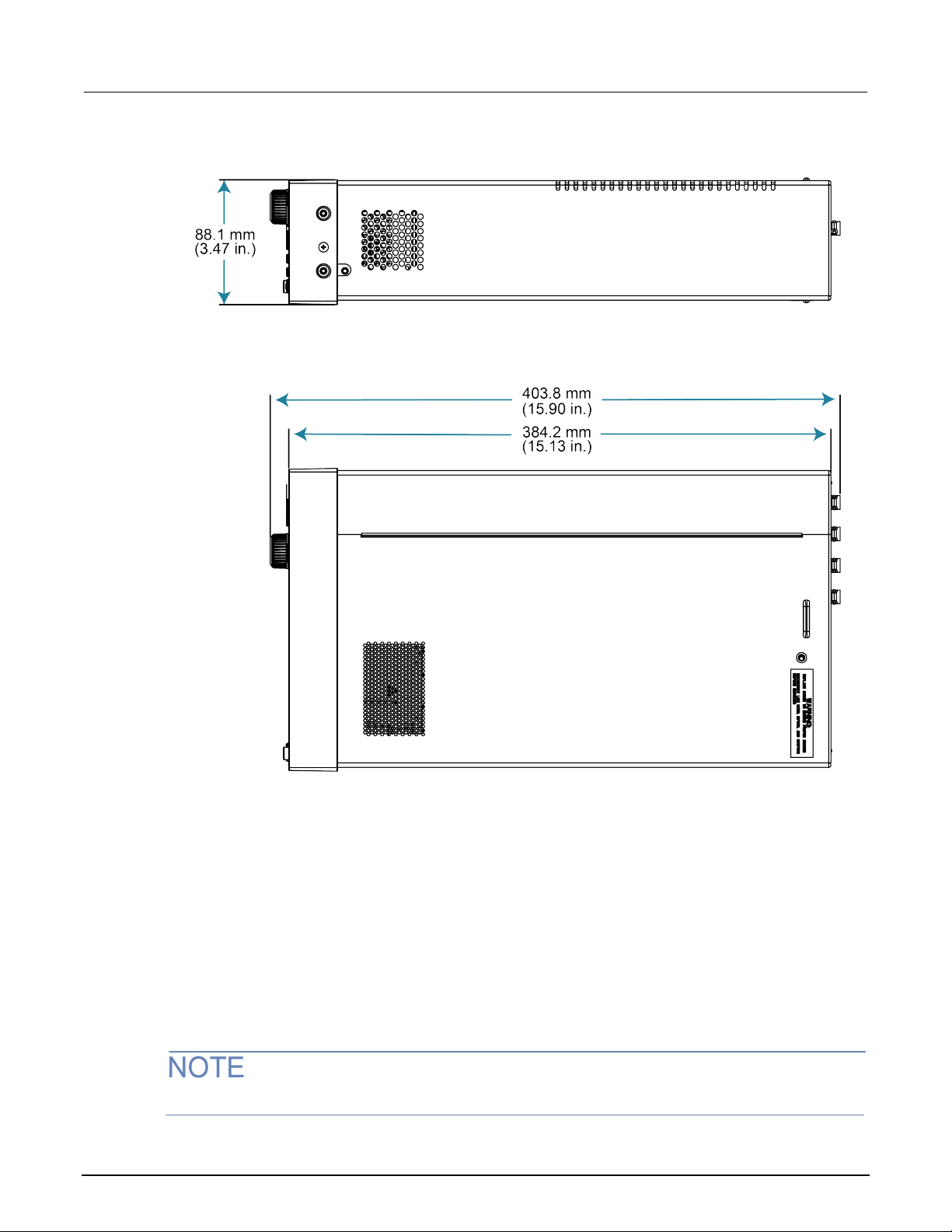
Section
Reference Manual
2: Installation Model 2470 High Voltage SourceMeter Instrument
Figure 5: 2470 top and side dimensions with handle and bumpers removed
Handle and bumpers
The 2470 has a handle and front and rear bumpers for using the instrument on a benchtop. The
handle rotates so that you can swing it below the bott om surface of the instrument to tilt the
instrument up for easier front-panel viewing or car ry the instrument.
Removing the handle and bumpers
You can remove handle and bumpers on the 2470 if you want to mount the instrument in a rack.
If you remove the handle and bumpers, be sure to store them for future benchtop use.
2-4 2470-901-01 Rev. B / September 2019
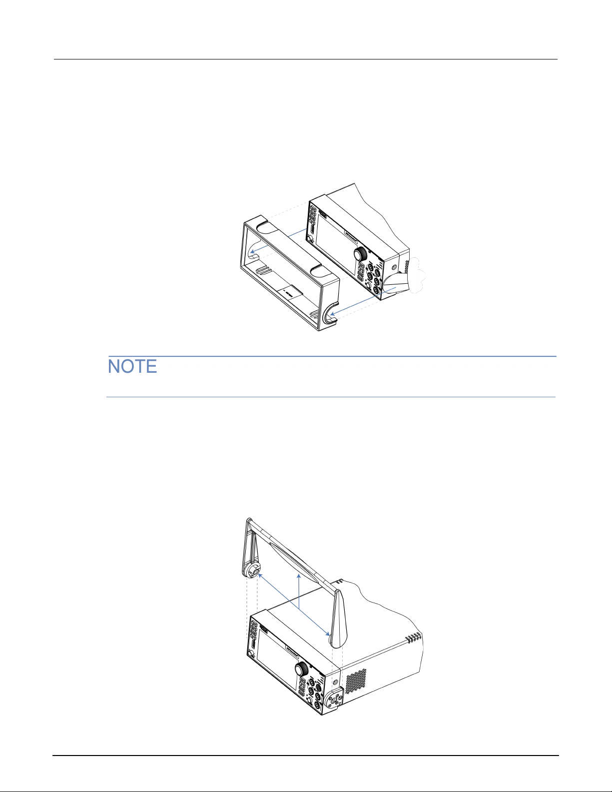
Model 2470
Installation
High Voltage SourceMeter Instrument Reference Manual Section 2:
To remove the bumpers:
1. Swivel the handle to a position above or below the instrument so that it will not interfere with the
removal of the front bumper.
2. Grasp the front bumper on each side of the 2470 and gently pull it toward you until the bumper
comes off the instrument.
Figure 6: Removing the front bumper
Remove all connections to the rear panel of the 2470 before removing the rear bumper.
3. To remove the rear bumper, repeat the procedure in st ep 2.
To remove the handle assembly:
1. Grasp the sides of the handle near where it attaches t o the instrument on both sides and gently
pull the handle ends apart to widen the handle as y ou slide it over the instrument case.
Figure 7: Removing the handle
2470-901-01 Rev. B / September 2019 2-5
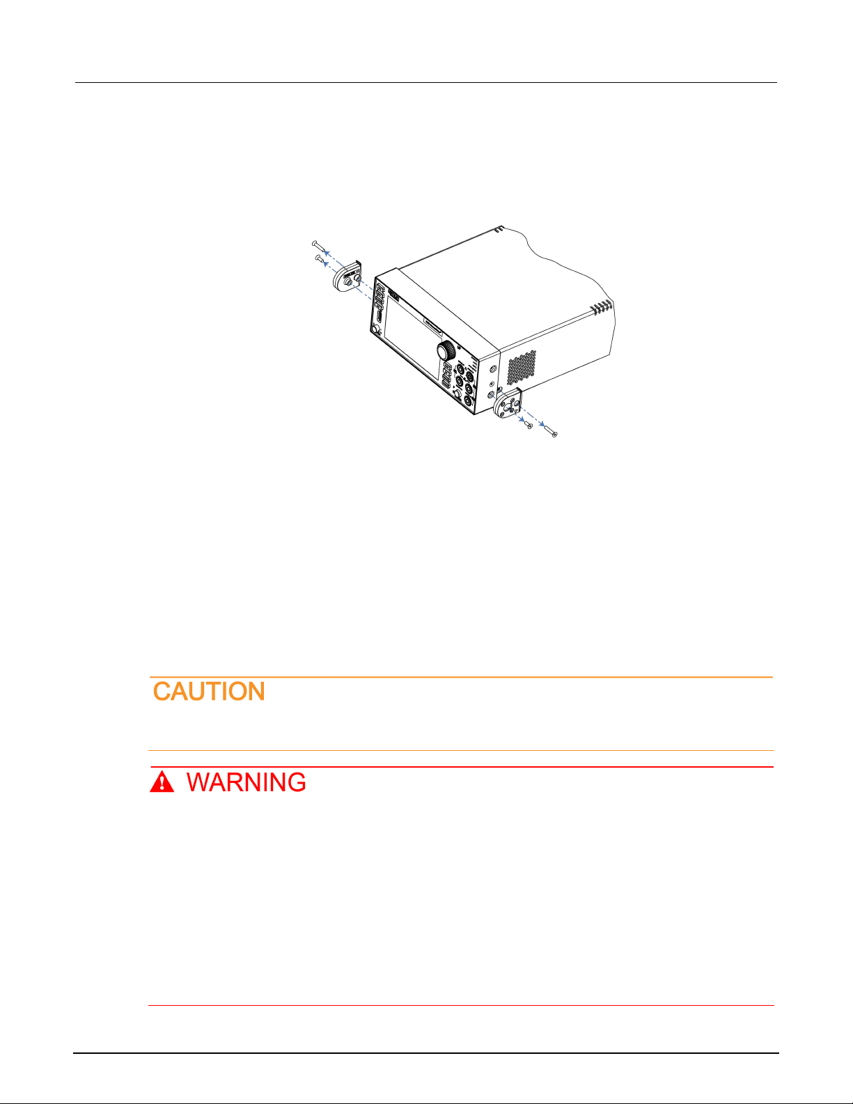
Section
Reference Manual
2: Installation Model 2470 High Voltage SourceMeter Ins trument
2. Use a Phillips screwdriver to loosen and remove the two screws holding the handle-mount
assembly to one side of the 2470. The handle-mount assembly will fall away from the instrument
chassis when the screws are removed.
Figure 8: Removing the handle mount
3. Repeat step 2 on the other side of the 2470.
4. Store the handle-mount assembly, screws, an d handle together for future use.
Instrument power
Follow the steps below to connect the 2470 to line po wer and turn on the instrument. The 2470
operates from a line voltage of 100 V to 240 V at a f requency of 50 Hz or 60 Hz. It automatically
senses line voltage and frequency. Make sure the operating voltage in your area is compatible.
You must turn on the 2470 and allow it to warm up for at least one hour to achieve rated accuracies.
Operating the instrument on an incorrect line voltage may cause damage to the instrument,
possibly voiding the warranty.
The power cord supplied with the 2470 contains a separate protective earth (safety ground)
wire for use with grounded outlets. When proper connections are made, the instrument
chassis is connected to power-line ground through the ground wire in the power cord. In
addition, a redundant protective earth connection is provided through a scre w on the rear
panel. This terminal should be connected to a known protective earth. In the event of a
failure, not using a properly grounded protective earth and grounded outlet may result in
personal injury or death due to electric shock.
Do not replace detachable mains supply cords with inadequately rated cords. Failure to use
properly rated cords may result in personal injury or death due to electric shock.
2-6 2470-901-01 Rev. B / September 2019
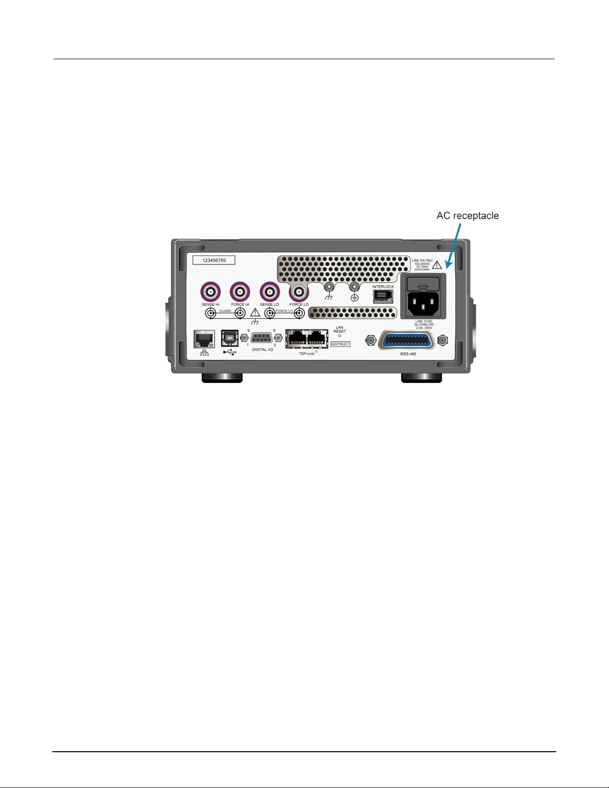
Model 2470
ion
High Voltage SourceMeter Instrument Reference Manual Section 2: Installat
Connect the power cord
To connect the power cord:
1. Make sure that the front-panel POWER switch is in the off (O) position.
2. Connect the female end of the supplied power cord to the AC receptacle on the rear panel.
3. Connect the male end of the power cord to a grounded AC outlet.
Figure 9: 2470 AC receptacle on rear panel
Power the instrument on or off
Before turning the instrument on, disconnect any devices under test (DUTs) from the 2470.
To turn your instrument on, press the front-panel POWER switch to place it in the on (|) position. The
instrument displays a status bar as it powers on. The home screen is displayed when power on
is complete.
To turn your instrument off, press the front-panel POWER switch to place it in the off (O) position.
Remote communications interfaces
You can choose from one of several communication i nterfaces to send commands to and receive
responses from the 2470.
You can control the 2470 from only one communications interface at a time. The first interface on
which the instrument receives a message takes control of the instrument. If another interface sends a
message, that interface can take control of t he inst rument. You may need to enter a password to
change the interface, depending on the setting of interface access.
2470-901-01 Rev. B / September 2019 2-7

Section
Reference Manual
2: Installation Model 2470 High Voltage SourceMeter Ins trument
The 2470 automatically detects the type of communications interface (LAN, USB, or GPIB) when you
connect to the respective port on the rear panel of t he inst rument. In most cases, you do not need to
configure anything on the instrument. In addit ion, you do not need to reboot if you change the type of
interface that is connected.
Supported remote interfaces
The 2470 supports the following remote interfaces:
• GPIB: IEEE-488 instrumentation general-purpose interface bu s
• USB: Type B USB port
• Ethernet: Local-area-network communications
• TSP-Link: A high-speed trigger synchronization and communications bus that test system
builders can use to connect multiple instruments in a master-and-subordinate configuration
For details about TSP-Link, see TSP-Link System Expansion Interface (on page 9-1
Comparison of the communications interfaces
The following topics discuss some of the advantages and disadvantages of the communications
interfaces that are available for the 2470.
Simplicity
The GPIB interface is the simplest configurat ion. Connections are simple, and the only necessary
software configuration is setting the instrum ent address.
An ethernet network is a simple configuration if you can use the automatic settings. It is more
complicated if you need to set it up manually. If you must set up y our et hernet network manually, you
need some knowledge of networking. In addition, your corporate information technology (IT)
department may have restrictions that preve nt using an ethernet network.
A USB interface is also simple to set up. However, it requires an instrument-specific device driver to
communicate with the instrument. This can limit the operating systems that are available for use with
the instrument.
Triggering
).
The GPIB interface provides the fastest, most consistent triggering. It has the lowest trigger latency of
the available communications types. Trigger latency is the time that it takes the trigger to go from the
computer to the instrument. GPIB also allows you to send triggers to multiple instruments
simultaneously.
2-8 2470-901-01 Rev. B / September 2019

Model 2470
Installation
High Voltage SourceMeter Instrument Reference Manual Section 2:
If you use a USB interface, it is difficult to synch ronize triggers that are sent to multiple instruments.
For applications that require synchronized t ri ggering, you must use digital I/O. The trigger latency with
a USB interface is higher than latency with a GPIB interface, but it is lower and more consistent than
latency with an ethernet interface.
Transfer rate
Of the available interfaces, USB has the fastest tra nsfer rate, followed by the ethernet and GPIB
interfaces. The GPIB interface, however, offers the most consistent transfer rate.
Instrument naming
Names for instruments that are named through NI-VISATM are in a human-readable format. USB
instrument names are not intended to be human -readable.
Distance and instrument limitations
For GPIB and USB interfaces, the cabling distance s between the controller and instrument or hub are
limited to 30 feet. In a system connected with GPIB or USB, you can have up to 15 instruments
attached to each controller.
The distances for ethernet interfaces are unlimi ted if the ethernet address of the instrument and ports
for the various services it uses are visible publi cly (for example, port 80 for web service). If you are
using an ethernet interface, you can communicate wit h an instrument anywhere in the world. In a
system that is connected through ethernet, the num ber of instruments you can attach to each
controller is only limited by the controller and the connections available on that controller.
Expense
The GPIB interface is the most expensive method because of the costs for cabling and related
equipment. Ethernet and USB connections are inex pensive options because most computers have
built-in ethernet and USB ports. In addition, cables and hubs for ethernet and USB interfaces
are inexpensive.
GPIB setup
This topic contains information about GPIB standards, bus connections, and primary
address selection.
The 2470 GPIB interface is IEEE Std 488.1 compliant and supports IEEE Std 488.2 common
commands and status model topology.
You can have up to 15 devices connected to a GPIB interface, including the controller. The maximum
cable length is the lesser of either:
• The number of devices multiplied by 2 m (6.5 ft)
• 20 m (65.6 ft)
You may see erratic bus operation if you ignore these limits.
2470-901-01 Rev. B / September 2019 2-9
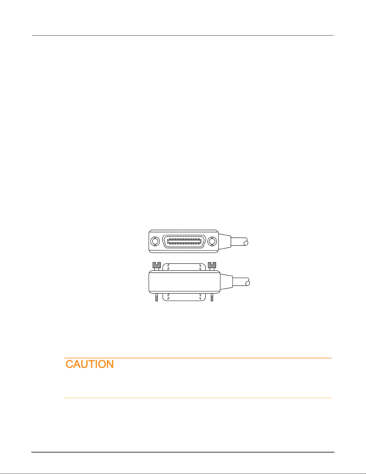
Section
Reference Manual
2: Installation Model 2470 High Voltage SourceMeter Ins trument
Install the GPIB driver software
Check the documentation for your GPIB controller for information about where to acquire drivers.
Keithley Instruments also recommends that you check the website of the GPIB controller for the latest
version of drivers or software.
It is important that you install the drivers before you connect the hardware. This prevents associating
the incorrect driver to the hardware.
Install the GPIB cards in your compute r
Refer to the documentation from the GPIB controller vendor for information about installing the
GPIB controllers.
Connect GPIB cables to your instrume nt
To connect a 2470 to the GPIB interface, use a cable equipped with standard GPIB connectors, as
shown below.
Figure 10: GPIB connector
To allow many parallel connections to one instrument, stack the connectors. Each connector has two
screws on it to ensure that connections remain secure. The figure below shows a typical connection
diagram for a test system with multiple instrum ents.
To avoid possible mechanical damage, stac k no more than three connectors on any one
instrument. To minimize interference caused by electromagnetic radiation, use only shielded
GPIB cables. Contact Keithley Instrumen ts for shielded cables.
2-10 2470-901-01 Rev. B / September 2019
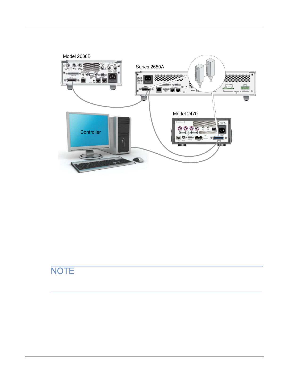
Model 2470
Installation
High Voltage SourceMeter Instrument Reference Manual Section 2:
Figure 11: IEEE-488 connection example
To connect the GPIB cable to the instrument:
1. Align the cable connector with the connector on the 2470 rear panel.
2. Attach the connector. Tighten the screws securely but do not overtighten them.
3. Connect any additional connectors from other in st ruments, as required for your application.
4. Make sure that the end of the cable is properly con nected to the controller.
Set the GPIB address
The default GPIB address is 18. You can set the address from 1 to 30 if it is unique in the system.
This address cannot conflict with an addres s t hat is assigned to another instrument or to the GPIB
controller.
GPIB controllers are usually set to 0 or 21. To be safe, do not configure any instrument to have an
address of 21.
The instrument saves the address in nonvolatile memory. It does not change when you send a reset
command or when you turn the power off and on agai n.
2470-901-01 Rev. B / September 2019 2-11

Section
Reference Manual
2: Installation Model 2470 High Voltage SourceMeter Ins trument
To set the GPIB address from the front panel:
1. Press the MENU key.
2. Select Communication.
3. Select the GPIB tab.
4. Set the GPIB Address.
5. Select OK.
You can also set the GPIB address using remote com m ands. Set the GPIB address with the SCPI
command :SYSTem:GPIB:ADDRess or the TSP command gpib.address.
Effect of GPIB line events on 2470
The GPIB has control lines that allow predefined i nformation, called events, to be transferred quickly.
The following information lists some of the GPIB l i ne events and how the 2470 reacts to them.
DCL
This event clears the GPIB interface. When the 2470 detects a device clear (DCL) event, it does
the following:
• Clears the input buffer, output queue, and command queue
• Cancels deferred commands
• Clears any command that prevents the processing of any other device command
A DCL event does not affect instrument settings and stored data.
GET
The group execute trigger (GET) command is a GPIB trigger that triggers the instrument to take
readings from a remote interface.
GTL
When the instrument detects the go to local (GTL ) event, it exits remote operation and enters local
operation. When the instrument is operating locally, you can control the instrument from the
front panel.
IFC
When the instrument detects an interface clear (IFC) event, the instrument enters the talker and the
listener idle state. When the instrument is in this state, the GPIB indicators on the front panel are
not displayed.
2-12 2470-901-01 Rev. B / September 2019

Model 2470
Installation
High Voltage SourceMeter Instrument Reference Manual Section 2:
An IFC event does not interrupt the transfer of comm and messages to and from the instrument.
However, messages are suspended. If the transfer of a response message from the instrument is
suspended by an IFC event, the transfer resumes when the instrument is addressed to talk. If transfer
of a command message to the instrument is su spended by an IFC event, the rest of the message can
be sent when the instrument is addressed to listen.
LLO
When the instrument detects a local-lockout (LLO) event, all front-panel controls except the OUTPUT
ON/OFF and POWER switches are disabled.
To enable the front panel, use the go-to-local (GTL) event.
REN
When the instrument detects the remote enable (RE N) event, it is set up for remote operation. The
instrument is not placed in remote mode when it detects the REN event; the instrument must be
addressed to listen after the REN event before it goes into remote mode.
You should place the instrument into remote mode before you attempt to program it using a
remote interface.
SDC
The selective device clear (SDC) event is similar t o the device clear (DCL) event. However, the SDC
event clears the interface for an individual inst rument instead of clearing the interface of all
instruments.
When the 2470 detects an SDC event, it will do the following for the selected instrument:
• Clears the input buffer, output queue, and comm and queue
• Cancels deferred commands
• Clears any command that prevents the processing of any other device command
An SDC event does not affect instrument settings an d stored data.
SPE, SPD
When the instrument detects the serial polling enabl e (SPE) and serial polling disable (SPD) events, it
sends the status byte of the instrument. This contains the serial poll byte of the instrument.
The serial poll byte contains information about internal functions. See the Status model (on page 16-1
for detail. Generally, the serial polling seque nce is used by the controller to determine which of
several instruments has requested service with t he SRQ line.
)
2470-901-01 Rev. B / September 2019 2-13

Section
eference Manual
2: Installation Model 2470 High Voltage SourceMeter Ins trument R
LAN communications
You can communicate with the instrument using a lo cal area network (LAN). The LAN interface can
be used to build flexible test systems that include web access. This section provides an overview of
LAN communications for the 2470.
When you connect using a LAN, you can use a web browser to access the internal web page of the
instrument and change some of the instrument set t i ngs.
The 2470 is a version 1.5 LXI Device Specificati on 2016 instrument that supports TCP/IP and
complies with IEEE Std 802.3 (ethernet LAN). There is one LAN port (located on the rea r panel of the
instrument) that supports full connectivity on a 10 Mbps or 100 Mbps network. The 2470 automatically
detects the speed.
The 2470 also supports Multicast DNS (mDNS) and DNS Service Discovery (DNS-SD), which are
useful on a LAN with no central administration.
Contact your network administrator to confirm your specific network requirements before settin g up a
LAN connection.
If you have problems setting up the LAN, refer to LAN t roubles hooti ng sugge stio ns (on page 2-22
LAN cable connection
The 2470 includes a LAN crossover cable. You can use this cable for the TSP-Link® network or LAN
communications.
However, you can use any standard LAN crossover cable (RJ-45, male-to-male) or straight-through
cable to connect your equipment. The instrument automatically senses which cable you have
connected.
The following figure shows the location of the LAN port on the rear panel of the instrument. Connect
the LAN cable between this connection and the LAN port on the computer.
You can connect the instrument to the LAN in a one-to-one, one-to-many, two network card, or
enterprise configuration, as described in the following topics.
).
Figure 12: 2470 LAN port
2-14 2470-901-01 Rev. B / September 2019

Model 2470
Installation
High Voltage SourceMeter Instrument Reference Manual Section 2:
One-to-one connection
With most instruments, a one-to-one connection is done only when you are connecting a single
instrument to a single network interface card.
A one-to-one connection using a network crossover cabl e c onnection is similar to a typical RS-232
system using a null modem cable. The crossover ca ble has its receive (RX) and transmit (TX) lines
crossed to allow the receive line input to be connected to the transmit line output on the
network interfaces.
Figure 13: One-to-one connection with a crossover cable
The 2470 supports Auto-MDIX and can use either normal LAN CAT-5 cables (patch) or crossover
cables. The instrument automatically adjusts t o s upport either cable.
One-to-many connection
With a LAN hub, a single network interface card ca n be connected to as many instruments as the hub
can support. This requires straight-through network (not cro ssover) cables for hub connections.
The advantage of this method is easy expansion of measurement channels when the test
requirements exceed the capacity of a single inst rument. With only the instruments connected to the
hub, this is an isolated instrumentation netwo rk. However, with a corporate network attached to the
hub, the instruments become part of the larger network.
2470-901-01 Rev. B / September 2019 2-15

Section
Reference Manual
2: Installation Model 2470 High Voltage SourceMeter Instrument
Figure 14: One-to-many connection using a network hub or switch
Two network card connection
If you need to connect independent corporate and i nstrumentation networks, two network interface
cards are required in the computer controller. Though the two networks are independent, stations on
the corporate network can access the instruments and the instruments can access the corporate
network using the same computer.
This configuration resembles a GPIB setup in which the computer is connected to a corporate
network, but also has a GPIB card in the computer to communicate with instruments.
Figure 15: Two network card connection
2-16 2470-901-01 Rev. B / September 2019

Model 2470
Installation
High Voltage SourceMeter Instrument Reference Manual Section 2:
Instrumentation connection to enterprise routers or servers
This connection uses an existing network infrast ructure to connect instruments to the computer
controller. In this case, you must get the networ k resources from the network administrator.
Usually, the instruments are kept inside the corporate firewall, but the network administrator can
assign resources that allow them to be outside the firewall. This allows instruments to be connected
to the internet using appropriate security methods. Data collection and distribution can be controlled
from virtually any location.
Figure 16: Instrumentation connection to enterprise routers or servers
Set up LAN communications on the inst rument
This section describes how to set up manual or automatic LAN communications on the instrument.
Check communication settings
Before configuring the LAN, you can check the communications settings on the instrument without
making any changes.
To check communications settings on the instrument:
1. Press the MENU key.
2. Under System, select Communication. The SYSTEM COMMUNICATIONS window opens.
3. Select one of the four tabs (GPIB, USB, LAN, or TSP-Link) to see the settings for that interface.
4. Press the EXIT key to leave the SYSTEM COMMUNICATIONS window without making
any changes.
2470-901-01 Rev. B / September 2019 2-17

Section
Reference Manual
2: Installation Model 2470 High Voltage SourceMeter Ins trument
Set up automatic LAN configuration
If you are connecting to a LAN that has a DHCP server or if you have a direct connection between the
instrument and a host computer, you can use aut om atic IP address selection.
If you select Auto, the instrument attempts to get an IP address from a DHCP server. If this fails, it
reverts to an IP address in the range of 169.254.1.0 through 169.254.254.255.
Both the host computer and the instrument should be set to use automatic LAN configuration.
Though it is possible to have one set to manual configuration, it is more complicated to set up.
To set up automatic IP address selection using the front panel:
1. Press the MENU key.
2. Under System, select Communication.
3. Select the LAN tab.
4. For TCP/IP Mode, select Auto.
Set up manual LAN configuration
If necessary, you can set the IP address on the instrument manually.
You can also enable or disable the DNS settings and assign a host name to the DNS server.
Contact your corporate information technology (I T ) department to secure a valid IP address for the
instrument when placing the instrument on a corporate network.
The instrument IP address has leading zeros, but the computer IP address cannot.
To set up manual IP address selection on the instrument:
1. Press the MENU key.
2. Under System, select Communication.
3. Select the LAN tab.
4. For TCP/IP Mode, select Manual.
5. Enter the IP Address.
5. Select Apply Settings to save your settings.
6. Enter the Gateway address.
7. Enter the Subnet mask.
8. Select Apply Settings to save your settings.
2-18 2470-901-01 Rev. B / September 2019

Model 2470
Installation
High Voltage SourceMeter Instrument Reference Manual Section 2:
Set up LAN communications on the comput er
This section describes how to set up the LAN communications on your computer.
Do not change your IP address without consulting your system administrator. If you enter an
incorrect IP address, it can prevent your computer f rom connecting to your corporate network or it
may cause interference with another network ed computer.
Record all network configurations before modifying any existing network configuration information on
the network interface card. Once the network configuration settings are updated, the previous
information is lost. This may cause a problem reconnecting the host computer to a corporate network,
particularly if DHCP is disabled.
Be sure to return all settings to their original co nfiguration before reconnecting the host computer to a
corporate network. Contact your system admini st rat or for more information.
Verify the LAN connection on the 2470
Make sure that your 2470 is connected to the netwo rk by confirming that your instrument was
assigned an IP address.
To verify the LAN connection:
1. Press the MENU key.
2. Under System, select Communication.
3. Select the LAN tab.
A green LAN status indicator on the lower left of the LAN tab confirms that your instrument was
assigned an IP address.
In addition, the green LAN LED on the upper right of the f ront panel is on when your instrument is
connected to the network.
Use the LXI Discovery Tool
To find the IP address of the 2470, use the LXI Discovery Tool, a utility that is available from the
Resources tab of the LXI Consortium website (lxistandard.org
).
2470-901-01 Rev. B / September 2019 2-19
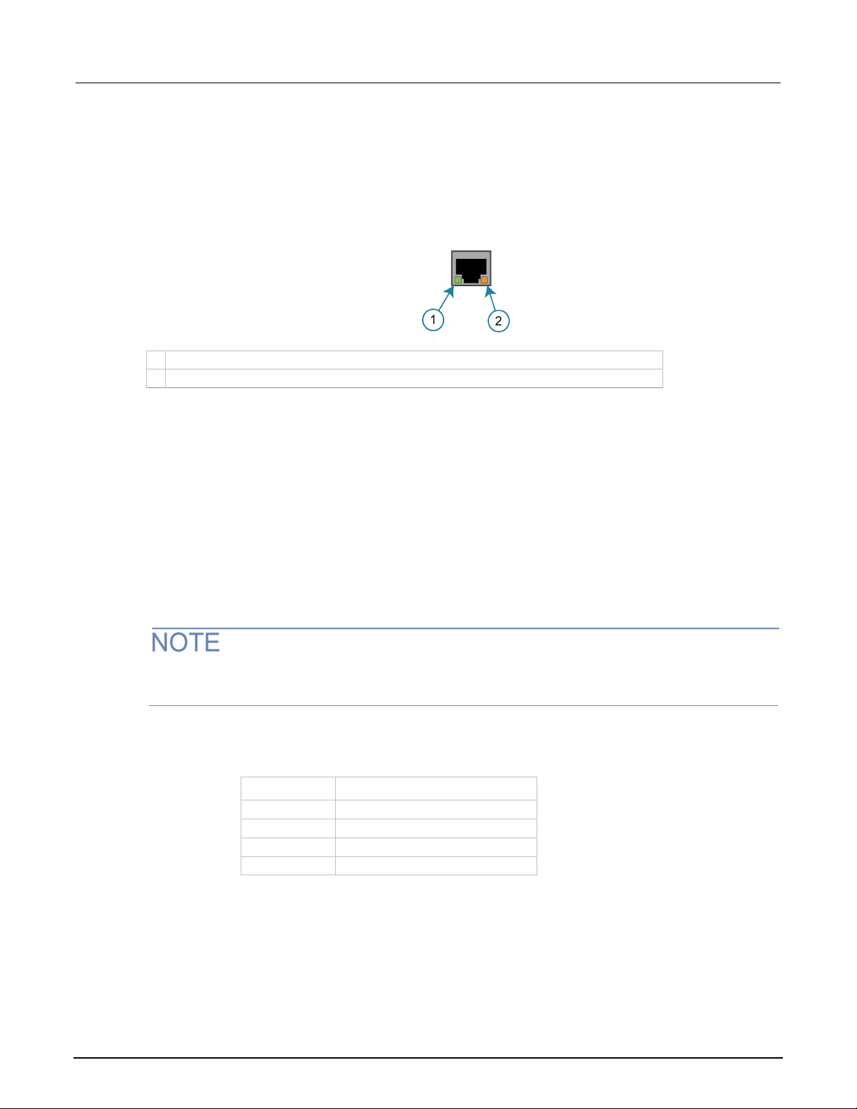
Section
Reference Manual
1
When lit, indicates that the LAN port is connected to a 100 Mbps network
2
When blinking, indicates that the por t is receiving or sending informat ion
23
Telnet
1024
VXI-11
5025
Raw socket
5030
Dead socket termination
2: Installation Model 2470 High Voltage SourceMeter Ins trument
LAN status LEDs
The figure below illustrates the two status light emi tting diodes (LED) that are on the LAN port of the
instrument. The table below the figure provi des explanations of the LED states.
If neither LED is lit, the network is not connected.
LAN interface protocols
You can use one of following LAN protocols to communicate with the 2470:
Figure 17: LAN status LEDs
• Telnet
• VXI-11
• Raw socket
You can also use a dead socket termination port to troubleshoot communication problems.
You can only use one remote interface at a time. A lthough multiple ethernet connections to the
instrument can be opened, only one can be used t o control the instrument at a time.
The port numbers for the LAN protocols and dead socket termination are listed in the following table.
LAN protocols
Port number Protocol
2-20 2470-901-01 Rev. B / September 2019

Model 2470
Installation
High Voltage SourceMeter Instrument Reference Manual Section 2:
Raw socket connection
All Keithley instruments that have LAN connections support raw socket communication. This means
that you can connect to the TCP/IP port on the instrument and send and receive commands. A
programmer can easily communicate with the i nstrument using the Winsock API on computers with
the Microsoft
®
Apple
computers.
VXI-11 connection
This remote interface is similar to GPIB and supports message boundaries, serial poll, and service
requests (SRQs). A VXI-11 driver or NI-VISA
NI-VISA and can be used with the VXI-11 interface. You can expect a slower connection with
this protocol.
Telnet connection
The Telnet protocol is similar to raw socket and can b e used when you need to interact directly with
the instrument. Telnet is often used for debugging and troubleshooting. You will need a separate
Telnet program to use this protocol.
®
Windows® operating system or using the Berkeley S ockets API on Linux® or
TM
software is required. Test Script Builder (TSB) uses
The 2470 supports the Telnet protocol, which you can use over a TCP/IP connection to send
commands to the instrument. You can use a Telnet connection to interact with scripts or send
real-time commands.
Dead socket connection
The dead socket termination (DST) port is used to terminate all existing ethernet connections. A dead
socket is a socket that is held open by the instrument because it has not been properly closed. This
most often happens when the host computer is turned off or restarted without first closing the socket.
This port cannot be used for command and control functions.
Use the dead socket termination port to manually disconnect a dead session on any open socket. All
existing ethernet connections will be termi nated and closed when the connection to the dead socket
termination port is closed.
Reset LAN settings
You can reset the password and the LAN settings from the rear panel by inserting a straightened
paper clip into the hole below LAN RESET.
2470-901-01 Rev. B / September 2019 2-21

Section
Reference Manual
2: Installation Model 2470 High Voltage SourceMeter Ins trument
LAN troubleshooting suggestions
If you are unable to connect to the web interface of the instrument, check the following items:
• The network cable is in the LAN port on the rear panel of the instrument, not one of the
TSP-Link
• The network cable is in the correct port on the com puter. The LAN port of a laptop may be
disabled when the laptop is in a docking station.
• The setup procedure used the configuration informat ion for the correct ethernet card.
• The network card of the computer is enabled.
• The IP address of the instrument is compatible wit h the IP address on the computer.
• The subnet mask address of the instrument is the same as t he subnet mask address of
the computer.
You can also try restarting the computer and the instrument.
To restart the instrument:
1. Turn the power to the instrument off, and then on.
®
ports.
2. Wait at least 60 seconds for the network configurat i on to be completed.
To set up LAN communications:
1. Press the MENU key.
2. Under System, select Communication.
3. Select the LAN tab.
4. Verify the settings.
If the above actions do not correct the problem, cont act your system administrator.
USB communications
To use the rear-panel USB port, you must have the Vi rt ual Instrument Software Architecture (VISA)
layer on the host computer. See How to install the Keithley I/O Layer (on page 2-33
more information.
VISA contains a USB-class driver for the USB Test and Measurement Class (USBTMC) protocol that,
once installed, allows the Microsoft
When you connect a USB device that implements the USBTMC or USBTMC-USB488 protocol to the
computer, the VISA driver automatically detects the device. Note that the VISA driver only
automatically recognizes USBTMC and USBTMC-USB488 devices. It does not recognize other USB
devices, such as printers, scanners, and storage devices.
) for
®
Windows® operating system to recognize the instrument .
In this section, "USB instruments" refers to devices that implement the USBTMC or
USBTMC-USB488 protocol.
2-22 2470-901-01 Rev. B / September 2019

Model 2
Installation
470 High Voltage SourceMeter Inst rument Reference Manual Section 2:
Using USB
To communicate from a computer to the instrument, you need a USB cable with a USB Type B
connector end and a USB Type A connector end. Y ou need a separate USB cable for each
instrument you plan to connect to the computer at the same time using the USB interface.
To connect an instrument to a computer using USB:
1. Connect the Type A end of the cable to the computer.
2. Connect the Type B end of the cable to the instrument.
3. Turn on the instrument power. When the computer det ect s t he new USB connection, the Found
New Hardware Wizard starts.
4. If the “Can Windows connect to Windows Update to s earch for software?” dialog box opens,
select No, and then select Next.
Communicate with the instrument
For the instrument to communicate with the USB device, you must use NI-VISATM. VISA requires a
resource string in the following format to conne ct to the correct USB instrument:
USB0::0x05e6::0x2470::[serial number]::INSTR
Where:
• 0x05e6: The Keithley vendor ID
• 0x2470: The instrument model number
• [serial number]: The serial number of the instrument (the serial num ber is also on the
rear panel)
• INSTR: Use the USBTMC protocol
The resource string is displayed on the bottom right of the System Communications screen. Select
Menu, then Communication to open the System Communicat i ons menu and select the USB tab.
You can also retrieve the resource string by runni ng t he K ei thley Configuration Panel, which
automatically detects all instruments connected to the computer.
5. On the “USB Test and Measurement device” dialog box, select Next, and then select Finish.
If you installed the Keithley I/O Layer, you can access the Keithley Configuration Panel through the
®
Microsoft
2470-901-01 Rev. B / September 2019 2-23
Windows® Start menu.
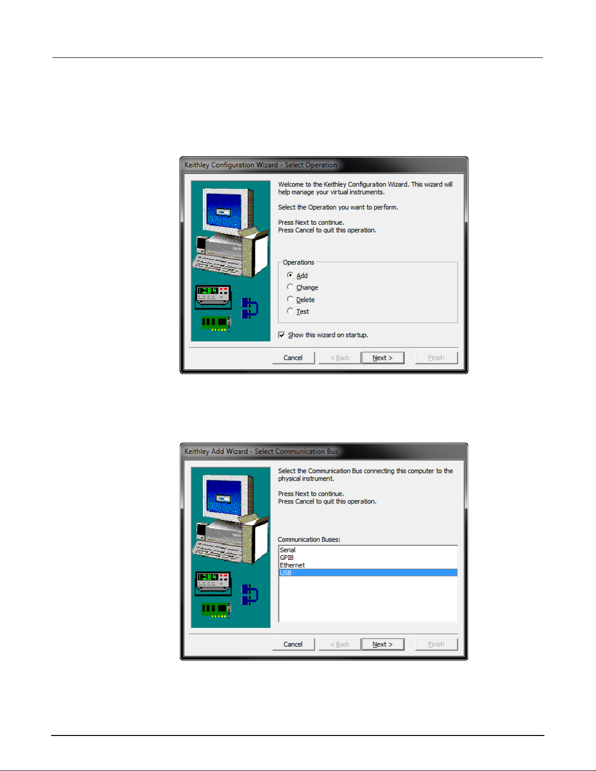
Section
Reference Manual
2: Installation Model 2470 High Voltage SourceMeter Ins trument
To use the Keithley Configuration Panel to determine the VISA resource string:
1. Select Start > Keithley Instruments > Keithley Configuration Panel. The Select Operation
dialog box is displayed.
Figure 18: Select Operation dialog box
2. Select Add.
3. Select Next. The Select Communication Bus dialog box is displayed.
Figure 19: Select Communication Bus dialog box
4. Select USB.
5. Select Next. The Select Instrument Driver dialog box is dis pl ayed.
2-24 2470-901-01 Rev. B / September 2019

Model 2470
Installation
High Voltage SourceMeter Instrument Reference Manual Section 2:
Figure 20: Select Instrument Driver dialog box
6. Select Auto-detect Instrument Driver - Model.
7. Select Next. The Configure USB Instrument dialog box i s displayed with the detected instrument
VISA resource string visible.
8. Select Next. The Name Virtual Instrument dialog box is displayed.
Figure 21: Name Virtual Instrument dialog box
9. In the Virtual Instrument Name box, enter a name that you want to use to refer to the instrument.
10. Select Finish.
11. Select Cancel to close the Wizard.
12. Save the configuration. From the Keithley Configuration Panel, select File > Save.
2470-901-01 Rev. B / September 2019 2-25
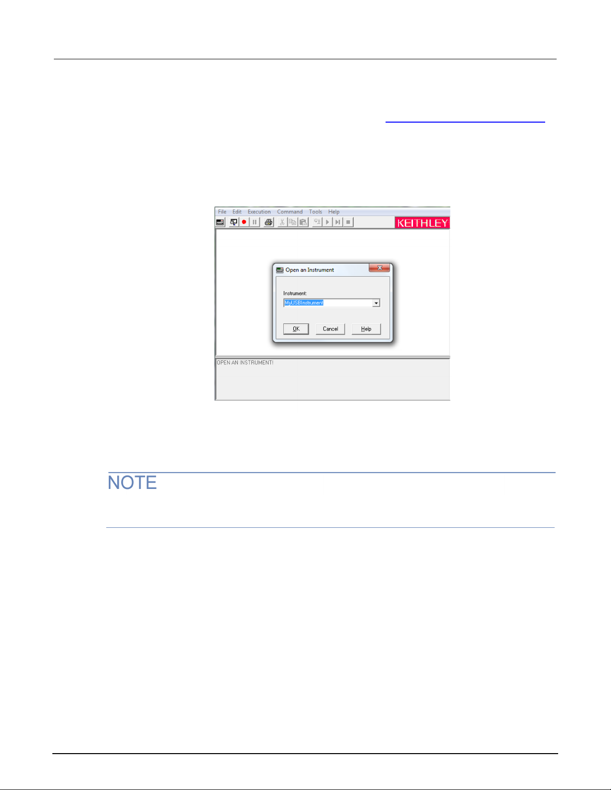
Section
Reference Manual
2: Installation Model 2470 High Voltage SourceMeter Ins trument
Verify the instrument through the Keithley Communicator:
1. Set the instrument to use the SCPI command set. Refer to How do I change the command set?
(on page 17-5) for instruction.
2. Select Start > Keithley Instruments > Keithley Communicator.
3. Select File > Open Instrument to open the instrument you just named.
Figure 22: Keithley Communicator Open an Instrument
4. Select OK.
5. Send a command to the instrument and see if it responds.
If you have a full version of NI-VISA on your system, you ca n run NI-MAX or the VISA Interactive
Control utility. See the National Instrume nt s documentation for information.
2-26 2470-901-01 Rev. B / September 2019

Model 2470
Installation
High Voltage SourceMeter Instrument Reference Manual Section 2:
2470 web interface
The 2470 web interface allows you to make settings and control your instrument through a web page.
The web page includes:
• Instrument status.
• The instrument model, serial number, firmware revision, and the last LXI message.
• An ID button to help you locate the instrument.
• A virtual front panel and command interface that you can use to control the instrument.
• Ability to download data from specific reading b uf fers into a CSV file.
• Administrative options and LXI information.
The instrument web page resides in the firmware of the instrument. Changes you make through the
web interface are immediately made in the inst rument.
When the LAN and instrument establish a connection, you can open the web page for the instrument.
To access the web interface:
1. Open a web browser on the host computer.
2. Enter the IP address of the instrument in the address box of the web browser. For example, if the
instrument IP address is 192.168.1.101, enter 192.168.1.101 in the browser address box.
3. Press Enter on the computer keyboard to open the instrument web page.
4. If prompted, enter a user name and password. The default is admin for both.
If the web page does not open in the browser, see LAN troubleshooting suggestions (on page 2-22).
To find the IP Address of the instrument, press the Comm unications indicator in the upper left corner
of the home screen.
2470-901-01 Rev. B / September 2019 2-27
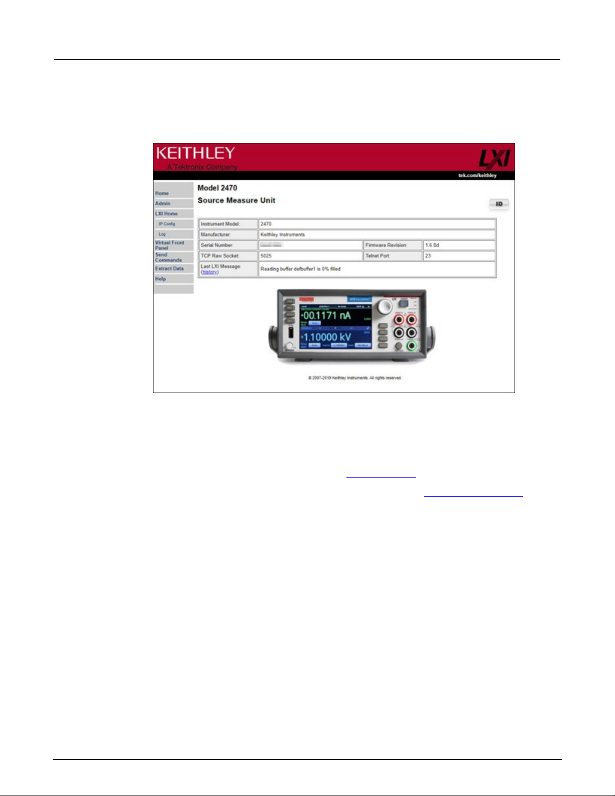
Section
Reference Manual
2: Installation Model 2470 High Voltage SourceMeter I nstrument
Web interface Home page
Figure 23: 2470 web interface Home page
The Home page of the instrument provides informati on about the instrument. It includes:
• The instrument model number, manufacturer, serial number, and firmware revision number.
• The TCP Raw Socket number and Telnet Port number.
• The last LXI message. The history link opens the LXI Home page (on page 2-29).
• The ID button, which allows you to identify the i nstrument. Refer to Identify the instrument (on
page 2-28).
Identify the instrument
If you have a bank of instruments, you can select the ID button to determine which one you are
communicating with.
To identify the instrument:
1. On the Home page, select the ID button. The button turns green and the LAN status indicator on
the front panel of the instrument blinks. On instruments with a front-panel interface, the System
Communications menu also opens and the LXI LAN indicator on the LAN tab blinks.
2. Select the ID button again to return the button to its original color and return the LAN status
indicators to steady on.
2-28 2470-901-01 Rev. B / September 2019

Model 2470
Installation
High Voltage SourceMeter Instrument Reference Manual Section 2:
LXI Home page
The LXI Home page displays instrument informati on, including the host name, MAC address, and
VISA resource string. You cannot change the information from this page.
You can use the host name instead of the IP address to connect to the instrument.
It also includes the ID button, which you can use to id entify the instrument. See
instrument (on page 2-28).
Change the IP configuration through the web interface
You can change the LAN settings, such as IP address, subnet mask, gateway, and DNS address,
through the web page of the instrument.
If you change the IP address through the web page, t he web page tries to redirect to the IP address
that is configured in the instrument. In some cases, this may fail. This generally happens if you switch
from IP address assignment that uses a static addr ess to IP address assignment that uses a DHCP
server. If this happens, you need to revert to either using the front panel to set the IP address or use
an automatic discovery tool to determine the new IP address.
You can also change the IP configuration through the front panel or with TSP and SCPI commands.
See Set up LAN communications on the instrument (on page 2-17
To change the IP configuration using the instrument web page:
1. Access the internal web page as described in
interface (on page 2-27).
Connecting to the instrument through the web
Identify the
) for information.
2. From the navigation bar on the left, in the LXI Home m enu, select IP Config.
3. Select Modify. The Modify IP Configuration page is displayed.
Figure 24: LXI - Modify IP Configuration page
2470-901-01 Rev. B / September 2019 2-29

Section
Reference Manual
2: Installation Model 2470 High Voltage SourceMeter Ins trument
4. Change the values.
5. Select Submit. The instrument reconfigures its settings, which may t ake a few moments.
You may lose your connection with the web interface after selecting Submit. This is normal and
does not indicate an error or failure of the operation. If this occurs, find the correct IP address and
reopen the web page of the instrument to continue.
Review events in the event log
Under LXI Home, the Log option opens the event log. T he event log records all LXI events that the
instrument generates and receives. The log include s t he following information:
• The EventID column, which shows the identifier of t he event that generated the event message.
• The System Timestamp column, which displays t he seconds and nanoseconds when the event
occurred.
• The Data column, which displays the text of the event message.
To clear the event log and update the information on the screen, select the Refresh button.
Using the 2470 virtual front panel
The Virtual Front Panel page allows you to control the instrument from a computer as if you were
using the front panel. You can operate the instrument using a mouse to select options.
The virtual front panel operates the same way as the actual front panel, with the following exceptions:
• The navigation control cannot be turned.
• You cannot switch the instrument on or off with the powe r switch.
• To scroll up or down on a screen, hold the left mouse button down and swipe up or down.
• To scroll right or left, hold the left mouse button down and swipe left or right. You can also select
the dots on the bar above the swipe screens to move f rom screen to screen.
• You cannot use pinch and zoom on the graph screen.
• You can improve communication speed with the instrument by right-clicking and clearing High
resolution. The default screen display resolution of 800 x 480 is reduced to 400 x 240 resolution
when high resolution is cleared.
• You can display the instrument display only with no other front-panel options by right-clicking and
selecting Screen only.
• You can download a screen capture by right-clicking and selecting Download screenshot.
2-30 2470-901-01 Rev. B / September 2019
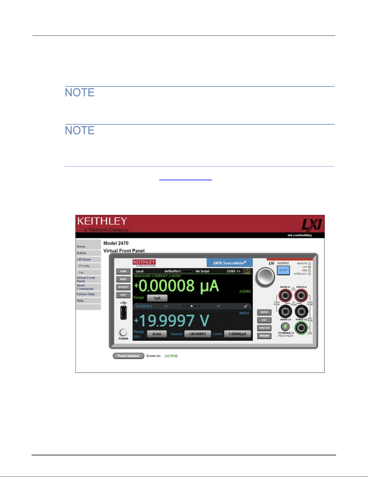
Model 2470
Installation
High Voltage SourceMeter Instrument Reference Manual Section 2:
To use the virtual front panel, you can use any of the standard web browsers. If you are using
Microsoft Internet Explorer, it must be versi on 9 or later. Earlier versions will not allow the swipe
motion to work.
Using graphing through the virtual front panel requires significant system resources and may slow
instrument operation.
The 2470 allows fewer than three clients to open the virtual front panel web page at the same time.
Only the first successfully connected client can operate the instrument. Other clients can view the
virtual front panel.
For information on the options, see Screen desc riptions (on page 3-9).
See the following figure for an example of the v irtual front panel.
Figure 25: Virtual front panel
2470-901-01 Rev. B / September 2019 2-31

Section
Reference Manual
2: Installation Model 2470 High Voltage SourceMeter Ins trument
Change the date and time through the web interface
You can change the instrument date and time through the web interface. This is the same as
changing the date and time through the front-panel S ystem Settings menu. The date and time is used
for the event log entries and data timestamps.
To change the date and time:
1. From the web interface page, select Admin.
2. In the Local time table, change the informati on as needed.
Change the password through the web i nterface
3. Select Submit.
You can change the instrument password from the web interface.
The default user name and password is admin. Note that you cannot change the user name; it
remains at admin even if the password has changed.
To change the password:
1. From the web interface Home page, select Admin.
2. In the Current password box, enter the presently used pass word.
3. In the New password and Confirm new password boxes, enter the new password.
4. Select Submit.
Send commands using the web inte rface
You can send individual commands using the web interface.
The active command set is listed above the Command box.
To send commands using the web page:
1. From the navigation bar on the left, select Send Commands.
2. If requested, log in.
3. In the Command box, enter the command.
4. Select Send Command to send the command to the instrument. The command is displayed in
the Command Output box. If there is a response to the command, it is displayed after the
command.
5. To view any events that have occurred, select Re turn Error.
6. To clear the Command Output list, select Clear Output.
2-32 2470-901-01 Rev. B / September 2019

Model 2470
nstallation
High Voltage SourceMeter Instrument Reference Manual Section 2: I
Extract buffer data using the web interface
The Extract Data page of the web interface allow s y ou to download reading buffer data from
the instrument.
To download buffer data:
1. From the web interface page, select Extract Data.
2. In the CSV File column, select the name of the file t hat you want to download.
3. Follow the instructions for your browser to open t he file. Typically, the file opens in
Microsoft Excel.
How to install the Keithley I/O Layer
Before installing, it is a good practice to chec k t he P roduct Support web page
(tek.com/product-support) to see if a later version of the Keithley I/O Layer is available. Search for
Keithley I/O Layer.
You can download the Keithley I/O Layer from the Keithley website.
The software installs the following components:
• Microsoft
TM
• NI
• NI-VISA
®
.NET Framework
IVI Compliance Package
TM
Run-Time Engine
• Keithley SCPI-based Instrument IVI-C driver
• Keithley I/O Layer
To install the Keithley I/O Layer from the Keit h ley website:
1. Download the Keithley I/O Layer Software from the P roduct Support web page
(tek.com/product-support), as described above. The software is a single compressed file and
should be downloaded to a temporary directory.
2. Run the downloaded file from the temporary directory.
3. Follow the instructions on the screen to install t he software.
4. Reboot your computer to complete the installation.
2470-901-01 Rev. B / September 2019 2-33

Section
Reference Manual
2: Installation Model 2470 High Voltage SourceMeter Ins trument
Modifying, repairing, or removing Keithley I/O Layer software
The Keithley I/O Layer interconnects many other installers.
To remove all the KIOL components, you need to uninstall the following applications using Control
Panel Add/Remove programs:
• National Instruments NI
• National Instruments NI-VISA
TM
IVI Compliance Package
TM
Run-Time Engine
• IVI Shared Components
• Visa Shared Components
• Keithley SCPI Driver
After uninstalling components, reboot the computer.
Interface access
You can specify that the control interfaces reque st access before taking control of the instrument.
There are several modes of access.
You can set one of the following levels of access to the inst rument:
• Full: Allows full access for all users from all interfaces
• Exclusive: Allows access by one remote interface at a time with logins required from
other interfaces
• Protected: Allows access by one remote interface at a t im e with passwords required on
all interfaces
• Lockout: Allows access by one interface (including t he front panel) at a time with passwords
required on all interfaces
The front panel is read-only when you are using a remote interface. You can view information and
swipe screens without being prompted to leave remote mode. If you attempt to make a change from
the front panel while the instrument is controlled from a remote interface, you will be prompted to
enter a password to gain access.
When you set access to full, the instrument accepts commands from any interface with no passwords
required. You can change interfaces as need ed.
When you set access to exclusive, you must log out of one remote interface before you can log in
with another interface. You do not need a password with this access.
Protected access is similar to exclusive access, except that you must enter a password when
logging in.
When you set access to locked out, a password is require d to change interfaces, including the
front-panel interface.
2-34 2470-901-01 Rev. B / September 2019

Model 2470
Installation
High Voltage SourceMeter Instrument Reference Manual Section 2:
Changing the interface access type
To change the type of interface access from the front panel:
1. Press the MENU key.
2. Under System, select Settings. The SYSTEM SETTINGS menu opens.
3. Select Interface Access.
Using SCPI commands
Send the command that is appropriate for the level of access you want to enable:
4. Select the level of password access control you w ant to enable.
SYSTem:ACCess FULL
SYSTem:ACCess EXCLusive
SYSTem:ACCess PROTected
SYSTem:ACCess LOCKout
Using TSP commands
Send the command that is appropriate for the level of access you want to enable:
localnode.access = localnode.ACCESS_FULL
localnode.access = localnode.ACCESS_EXCLUSIVE
localnode.access = localnode.ACCESS_PROTECTED
localnode.access = localnode.ACCESS_LOCKOUT
Changing the password
If interface access is set to Protected or Lockout , you must enter a password to change to a new
control interface. You can set the password, as desc ribed below.
The default password is admin.
To change the password from the front panel:
1. Press the MENU key.
2. Under System, select Settings.
3. Select Password. A keypad opens.
4. Enter the new password.
5. Select the OK button on the displayed keyboard. A verifi cation screen is displayed.
6. Enter the new password.
7. Select the OK button on the displayed keyboard. The password is reset.
You can reset the password by pressing the MENU key, selecti ng Info/Manage (under System), and
selecting Password Reset. When you do this, the password returns to the default setting.
2470-901-01 Rev. B / September 2019 2-35

Section
Reference Manual
2: Installation Model 2470 High Voltage SourceMeter Ins trument
To change the password using SCPI commands:
:SYSTem:PASSword:NEW "<password>"
Where <password> is the new password.
To change the password using TSP commands:
localnode.password = "password"
Where password is the new password.
Switching control interfaces
When the interface access is set to anything other t han Ful l , you need to log in to the instrument from
the new interface before you can change any setti ngs.
If you are changing to the front panel, when you att empt to make a selection, the Display Lockout Enter Password keypad is displayed. Enter t he password and select the OK button on the displayed
keyboard.
When you change the remote interface, you must send the following TSP or SCPI command before
sending commands:
login password
Replace password with the instrument password.
Determining the command set you will use
You can change the command set that you use with the 2470. The remote command sets that are
available include:
• SCPI: An instrument-specific language built on t he S CPI standard.
• TSP: A scripting programming language that contains i nst rument-specific control commands that
can be executed from a stand-alone instrument. You can use TSP to send individual commands
or use it to combine commands into scripts.
If you change the command set, reboot the instrument.
You cannot combine the command sets.
As delivered from Keithley Instruments, the 2470 is set to work with the SCPI command set.
2-36 2470-901-01 Rev. B / September 2019

Model 2470
Installation
High Voltage SourceMeter Instrument Reference Manual Section 2:
To set the command set from the front panel:
1. Press the MENU key.
2. Under System, select Settings.
3. Select the appropriate Command Set.
You are prompted to confirm the change to the command set and reboot.
To verify which command set is selected from a r emote interface, send the command:
*LANG?
To change to the SCPI command set from a remote interface, send the command:
*LANG SCPI
Reboot the instrument.
To change to the TSP command set from a remote interface, send the command:
*LANG TSP
Reboot the instrument.
System information
You can get the serial number, firmware build, det ected line frequency, calibration verify date,
calibration adjust date, and calibration adjust count information from the instrument.
To view the version and serial number information from the front panel:
1. Press the MENU key.
2. Under System, select Info/Manage.
The firmware version and serial number are displayed at the top of the screen.
To view the calibration information from the front panel:
1. Press the MENU key.
2. Under System, select Calibration.
The adjust date, adjust count, and calibration date are displayed.
To view the line frequency information from the front panel:
1. Press the MENU key.
2. Under System, select Settings.
3. Scroll down to display the line frequency.
2470-901-01 Rev. B / September 2019 2-37

Section
Reference Manual
2: Installation Model 2470 High Voltage SourceMeter Ins trument
To view system information using SCPI commands:
To retrieve the manufacturer, model number, serial number, and firmware version, send the
command:
*IDN?
To read the line frequency, send the command:
SYStem:LFRequency?
The firmware build, memory available, and facto ry calibration date are not available when using
SCPI commands.
To view system information using TSP commands:
To read the model number, send the command:
print(localnode.model)
To read the serial number, send the command:
print(localnode.serialno)
To read the firmware version, send the command:
print(localnode.version)
To read the line frequency, send the command:
print(localnode.linefreq)
The factory calibration date is not available with T SP commands.
You can also create user-defined strings to store c ustom, instrument-specific information in the
instrument, such as department number, asset nu m ber, or manufacturing plant location. See the
TSP
command reference (on page 14-1) for detail about t he userstring functions.
2-38 2470-901-01 Rev. B / September 2019
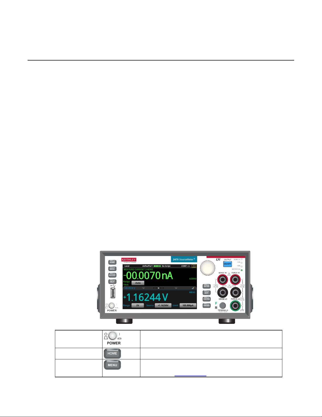
Saving front-panel settings into a macro script ....................... 3-52
Turns the instrument on or off. T o turn the instrument on, press
press the power switch so that it is in t he off position (O).
Returns the display to the home scr een.
Opens the main menu. Press the icons on t he main menu to open
details, refer to Menu overview (o n page 3-18).
Section 3
Instrument description
In this section:
Front-panel overview ................................................................ 3-1
Rear-panel overview ................................................................ 3-3
Turn the 2470 output on or off .................................................. 3-4
Touchscreen display ................................................................ 3-5
Screen descriptions .................................................................. 3-9
Menu overview ....................................................................... 3-18
APPS Manager ...................................................................... 3-39
Display features ..................................................................... 3-40
Instrument sounds .................................................................. 3-44
Saving setups ......................................................................... 3-45
Resets .................................................................................... 3-49
Using the event log ................................................................ 3-50
Front-panel overview
The front panel of the 2470 is shown below. Descriptions of the controls on the front panel follow
the figure.
POWER switch
HOME key
Figure 26: 2470 front panel
the power switch so that it is in the on pos i tion (|). To turn it off,
MENU key
source, measure, views, trigger, scripts, and system screens. For
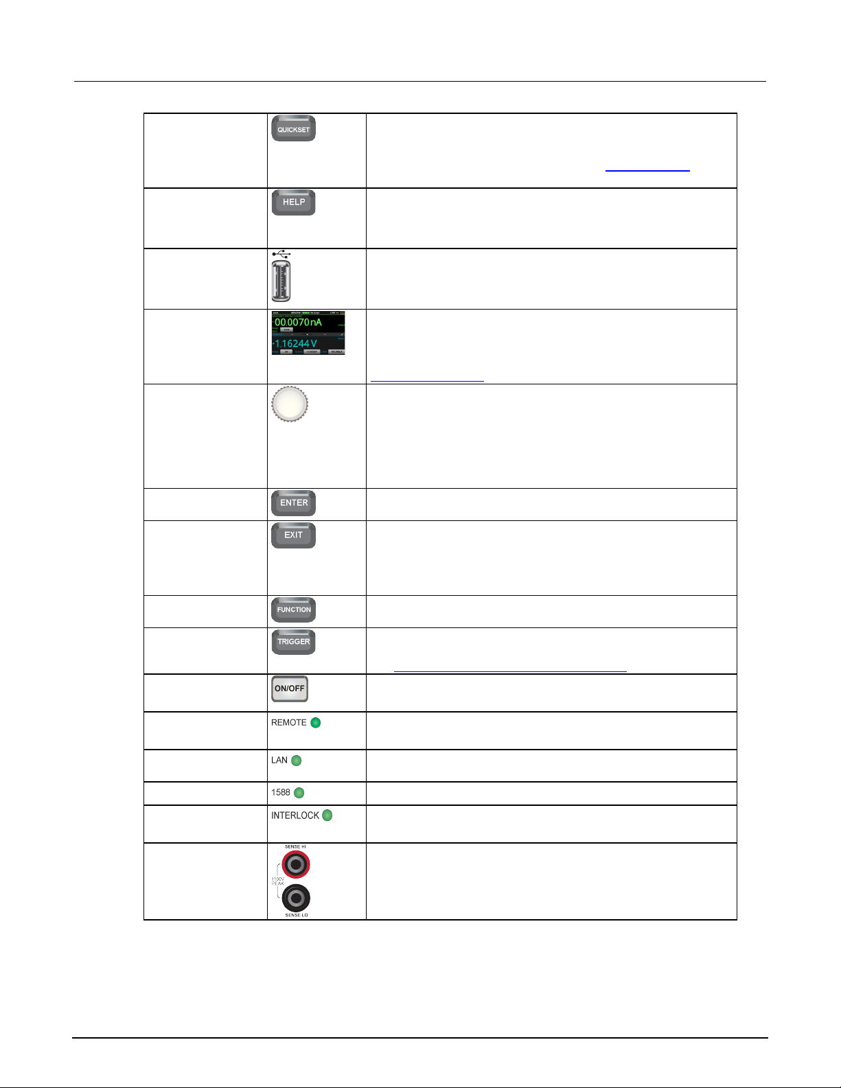
Section
Reference Manual
Opens a menu of preconfigured setups, including voltmeter,
page 3-18).
Opens help for the area or item that is selected on the display. If
help, hold the on-screen button while pressing the HELP key.
Saves reading buffer data and scr een snapshots to a USB flash
drive.
The 2470 has a high-resolution, fiv e -inch color touchscreen
Touchscreen display (on page 3-5) for details.
Moves the cursor and makes screen selections.
or allows you to edit the selected fiel d.
Selects the highlighted choice or allows you to edit the selected
field.
Returns to the previous screen or closes a dialog box. For
to the main menu screen.
Displays instrument functions. To select a function, touch the
function name on the screen.
Accesses trigger-related settings and operations. The action of
see Switching between measurement methods (on page 8-2).
Turns the output source on or off. The switch illuminates when the
Illuminates when the instrument is connected to a local area
network (LAN).
1588 functionality is not suppor ted at this time.
Use the SENSE HI and SENSE LO terminal connections to
3: Instrument description Model 2470 High Voltage SourceMeter Ins trument
QUICKSET key
HELP key
USB port
Touchscreen
Navigation control
ENTER key
ammeter, ohmmeter, and power sup ply. Also allows you to
choose source and measure functions and adjust performance for
better resolution or speed. For detail s , see QuickSet menu (on
there is no selection when you press the HELP key, it displays
overview information for the screen you are viewing. To display
drive. You can also store and retrieve scripts to and from a USB
flash drive. The flash drive must be formatted as a FAT or FAT32
display. The touchscreen accesses swipe screens and menu
options. You can access additional screens by pressing the
front-panel MENU, QUICKSET, and FUNCTION keys. Refer to
Turning the navigation control: Moves the cursor to highlight a
list value or menu item so that you can s elect it. Turning the
control when the cursor is in a value entry field increases or
decreases the value in the field.
Pressing the navigation control: Selects the highlighted choice
EXIT key
FUNCTION key
TRIGGER key
OUTPUT ON/OFF
switch
REMOTE LED
indicator
LAN LED indicator
1588 LED indicator
INTERLOCK LED
indicator
Sense terminals
example, press the EXIT key when the main m enu is displayed to
return to the home screen. When you ar e viewing a subscreen
(for example, the Event Log screen), press the EXIT key to return
the TRIGGER key depends on the instrument state. For details,
source output is on.
Illuminates when the instrument is controlled through a remote
interface.
Illuminates when the interlock is enabled.
measure voltage at the device under test (DUT). When you use
sense leads, measurement of the voltage drop across the force
leads is eliminated. This produc es more accurate voltage sourcing
and measurement at the DUT.
3-2 2470-901-01 Rev. B / September 2019
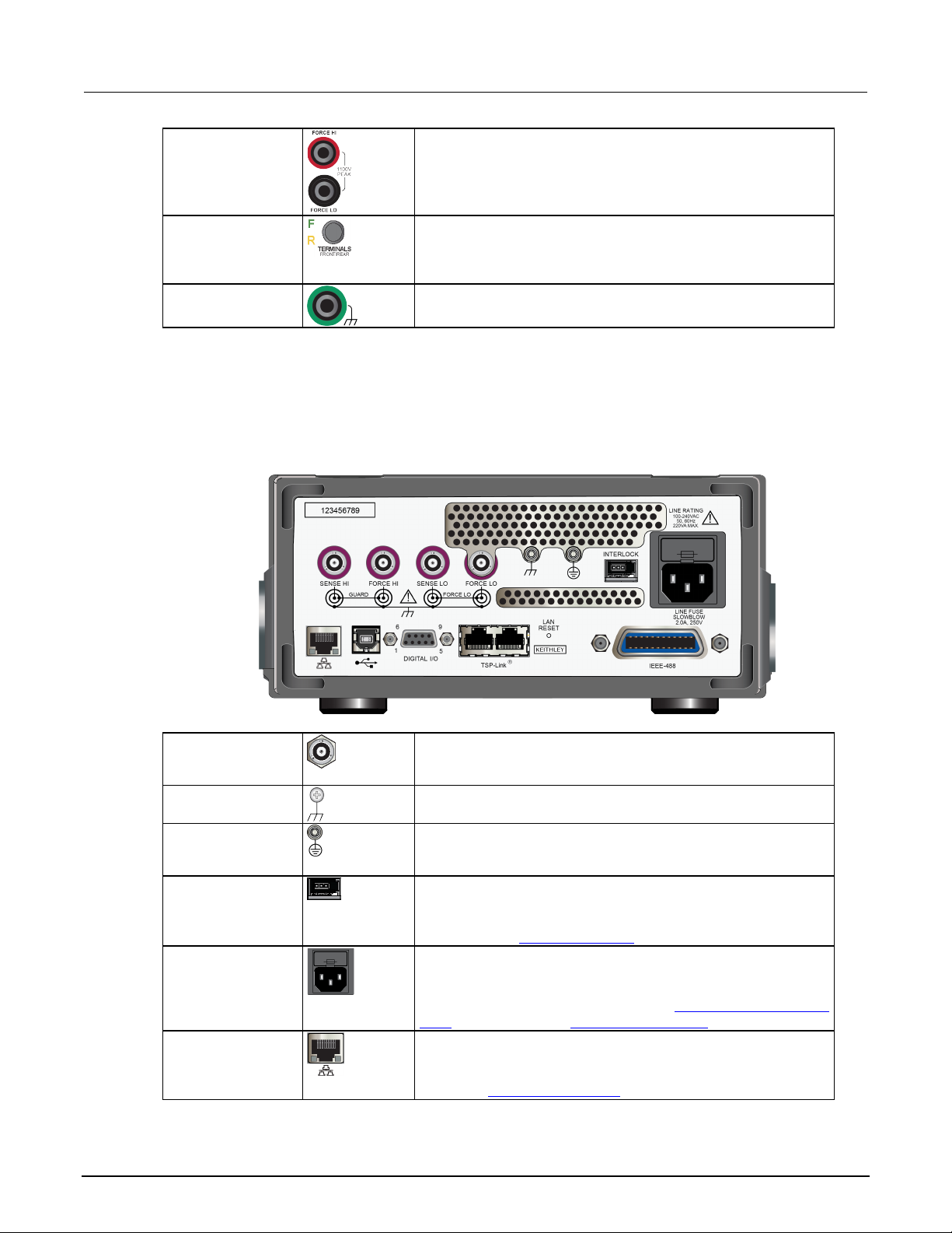
Model 2470
Instrument description
Use FORCE HI and FORCE LO terminal connections to source or
Activates the terminals on the front or rear panel. When the
active, a yellow “R” is visible to t he left of the switch.
These triaxial terminals provide connections for SENSE HI and
ground.
Ground screw for connections to chas s i s ground. This provides a
Ground screw for connection to protective earth (safety ground).
AWG or larger).
Interlock connection for use with an i nterlock switch, such as a
For details, see Using the interlock (on page 4-3).
Connect the line cord to the power receptacle and a grounded AC
or off (on page 2-7) and Line fuse replacement (on page 10-1).
Supports full connectivity on a 10 M bps or 100 Mbps network. The
LAN). See LAN communications (on page 2-14).
High Voltage SourceMeter Instrument Reference Manual Section 3:
Force terminals
FRONT/REAR
TERMINALS switch
Chassis
connection
Rear-panel overview
The rear panel of the 2470 is shown below. Descri pt i ons of the options follow the figure.
sink voltage or current to or from a device under test (DUT).
front-panel terminals are activ e, a green “F” is visible to the left of
the FRONT/REAR switch. When the rear-panel terminals are
Banana jack connector that provides a chassis connection.
Figure 27: 2470 rear panel
SENSE and FORCE
connectors
Chassis ground
Protective earth
(safety ground)
Interlock connector
Line fuse and
power receptacle
LAN port
2470-901-01 Rev. B / September 2019 3-3
SENSE LO, FORCE HI and FORCE LO, GUARD, and chassis
connection terminal to the equipm ent frame.
Connect to protective earth using recommended wire size (#16
test fixture. When properly connected, the safety interlock of the
2470 places the outputs of the instr ument in a safe state.
power outlet. The line fuse, located jus t above the power
receptacle, protects the power line input of the instrument. For
safety precautions and other details, see Power the instrument on
2470 is a version 1.5 LXI Device Specification 2016 instrument
that supports TCP/IP and complies with IEEE Std 802.3 (ethernet
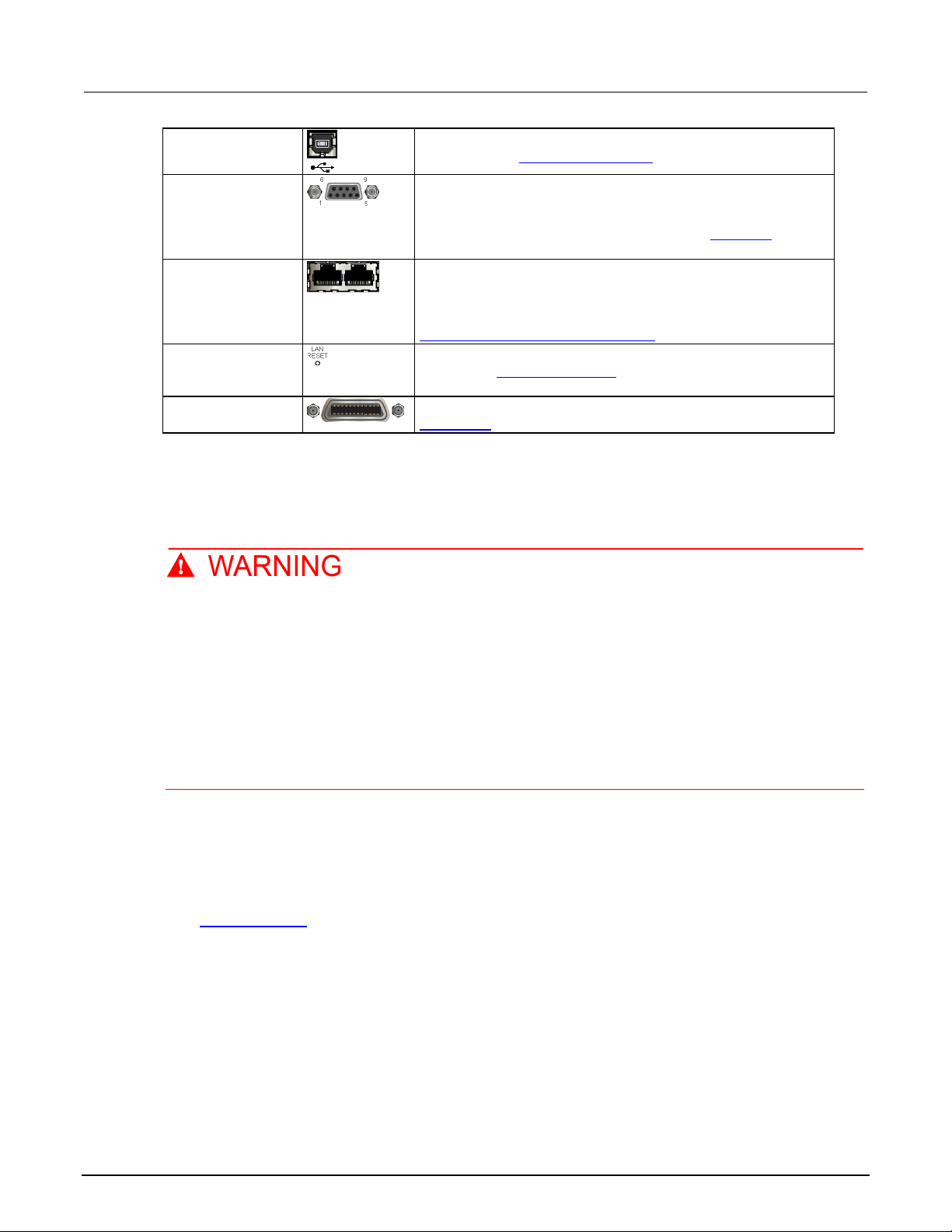
Section
Reference Manual
USB-B connection for communication, control, and data transfer.
A digital input/output port that detects and outputs digital signals.
page 8-12) for information.
TSP-Link® system expansion interface, which builders of test
TSP-Link System Expansion Interface (on page 9-1).
Reverts the LAN settings and the inst rument password to default
information.
GPIB connection; the default sett i ng for the 2470 is 18. Refer to
GPIB setup (on page 2-9) for details.
3: Instrument description Model 2470 High Voltage SourceMeter Ins trument
USB port
Digital I/O port
TSP-Link ports
LAN reset
IEEE-488 port
For details, see USB communications (on page 2-22).
The port provides six digital I/O li nes . Each output is set high
(+5 V) or low (0 V) and can read high or low logic levels. Each
digital I/O line is an open-drain signal. Refer to Digital I/O (on
systems can use to connect multiple instruments in a master and
subordinate configuration. T SP -Li nk i s a high-speed trigger
synchronization and communicat i on bus. For details, see
values. See Reset LAN settings (on page 2-21) for more
Turn the 2470 output on or off
You can turn the 2470 output on from the front panel or by sending remote commands.
Turning the 2470 output off does not place the instrument in a safe state (an interlock is
provided for this function).
Hazardous voltages may be present on all output and guard terminals. To prevent electrical
shock that could cause injury or death, never make or break connections to the 2470 while
the instrument is powered on. Turn off the equipment from the front panel or disconnect the
main power cord from the rear of the 2470 before handling cables. Putting the equipment into
an output-off state does not guarantee that the outputs are powered off if a hardware or
software fault occurs.
When the source of the instrument is turned off , it may not completely isolate the instrument from the
external circuit. You can use the Output Off setting to place the 2470 in a known, noninteractive state
during idle periods, such as when you are changing the device under test. The output-off states that
can be selected for a 2470 are normal, high-impe dance, zero, or guard.
See Output-off state (on page 4-16
) for additional details.
Using the front panel:
Press the OUTPUT ON/OFF switch. The instrument is in the output-on state when the switch is
illuminated. The instrument is in the output-off state when the switch is not illuminated.
3-4 2470-901-01 Rev. B / September 2019

Model 2470
Instrument description
High Voltage SourceMeter Instrument Reference Manual Section 3:
Using SCPI commands:
To turn the output on, send the command:
:OUTPut:STATe ON
To turn the output off, send the command:
:OUTPut:STATe OFF
Using TSP commands:
To turn the output on, send the command:
smu.source.output = smu.ON
To turn the output off, send the command:
smu.source.output = smu.OFF
Touchscreen display
The touchscreen display gives you quick front-panel access to source and measure settings, system
configuration, instrument and test status, reading buffer information, and other instrument functionality.
The display has multiple swipe screens that y ou can access by swiping the front panel. You can
access additional interactive screens by pres sing the front-panel MENU, QUICKSET, and
FUNCTION keys.
Do not use sharp metal objects, such as tweezers or screwdrivers, or pointed objects, such
as pens or pencils, to touch the touchscreen. It is strongly recommended that you use only
fingers to operate the instrument. Use of clean-room gloves to operate the touchscreen
is supported.
Select items on the touchscreen
To select an item on the displayed screen, do one of the following:
• Touch it with your finger
• Turn the navigation control to highlight the item, and then press the navigation control to select it
The following topics describe the 2470 touchscreen in more detail.
2470-901-01 Rev. B / September 2019 3-5
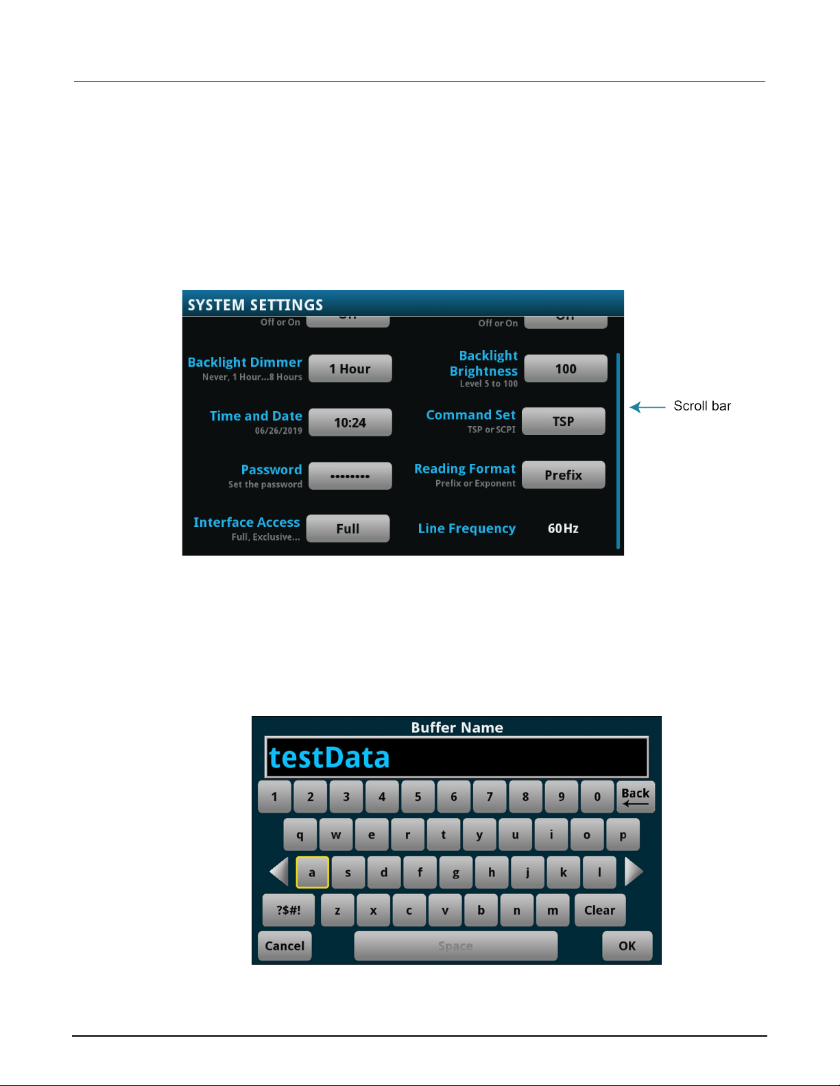
Section
Reference Manual
3: Instrument description Model 2470 High Voltage SourceMeter Instrument
Scroll bars
Some of the interactive screens have additional opti ons that are only visible when you scroll down the
screen. A scroll indicator on the right side of the touchscreen identifies these screens. Swipe t he
screen up or down to view the additional options.
The figure below shows a screen with a scroll bar.
Figure 28: Scroll bar
Enter information
Some of the menu options open a keypad or keybo ard that you can use to enter information. For
example, if you are setting the name of a buffer from the front panel, you see the keyboard shown in
the following figure.
Figure 29: 2470 front-panel keyboard
3-6 2470-901-01 Rev. B / September 2019

Model 2470
Instrument description
High Voltage SourceMeter Instrument Reference Manual Section 3:
You can enter information by touching the screen to select characters and options from the keypad or
keyboard. You can move the cursor in the entry box by touching the screen. The cursor is moved to
the spot in the entry box where you touched the sc reen.
Some numeric keypads include Min, Max, and Inf options. Min sets the lowest value for the setting.
Max sets the highest value. Inf sets the value to infinite. On number keypads, you can also use the
navigation control to move the cursor to a specific number.
On keyboards and keypads, you can use the navigation control to select characters.
To set values using the number keypad with the navigation control:
1. Turn the control to underline the character that you want to change.
2. Press the control to select the character for edit.
3. Turn the control to scroll through the options.
4. Press the control to set the character.
Adjust the backlight brightness and dimmer
You can adjust the brightness of the 2470 touchscreen display and buttons from the front panel or
over a remote interface. You can also set the backli ght to dim after a specified period has passed with
no front-panel activity (available from the f ront-panel display only). The backlight settings set through
the front-panel display are saved through a reset or power cycle.
Screen life is affected by how long the screen is on at full brightness. The higher the brightness
setting and the longer the screen is bright, the shorter the screen life.
To adjust the backlight brightness from the front panel:
1. Press the MENU key.
2. Under System, select Settings.
3. Select Backlight Brightness.
4. Drag the sliding adjustment to set the backlight .
5. Press the ENTER key to save the change.
5. Select OK to save your setting.
To set the backlight dimmer from the front panel:
1. Press the MENU key.
2. Under System, select Settings.
3. Select Backlight Dimmer. The Backlight Dimmer dialog box opens.
4. Select a dimmer setting.
2470-901-01 Rev. B / September 2019 3-7

Section
Reference Manual
3: Instrument description Model 2470 High Voltage SourceMeter Ins trument
To adjust the brightness using the SCPI remote interface, send the following command:
:DISPlay:LIGHt:STATe <brightness>
Where <brightness> is one of the following options:
• Full brightness: ON100
• 75% brightness: ON75
• 50% brightness: ON50
• 25% brightness: ON25
• Display off: OFF
• Display, key lights, and all indicators off: BLACkout
To adjust the backlight using TSP commands, send the following command:
display.lightstate = brightness
Where brightness is one of the following options:
• Full brightness: display.STATE_LCD_100
• 75% brightness: display.STATE_LCD_75
• 50% brightness: display.STATE_LCD_50
• 25% brightness: display.STATE_LCD_25
• Display off: display.STATE_LCD_OFF
• Display, key lights, and all indicators off: display.STATE_BLACKOUT
Event messages
During operation and programming, front-panel messages may be displayed. Messages are
information, warning, or error notifications. For i nf ormation on event messages, refer to
event log (on page 3-50).
Using the
Figure 30: Example front-panel error message
3-8 2470-901-01 Rev. B / September 2019
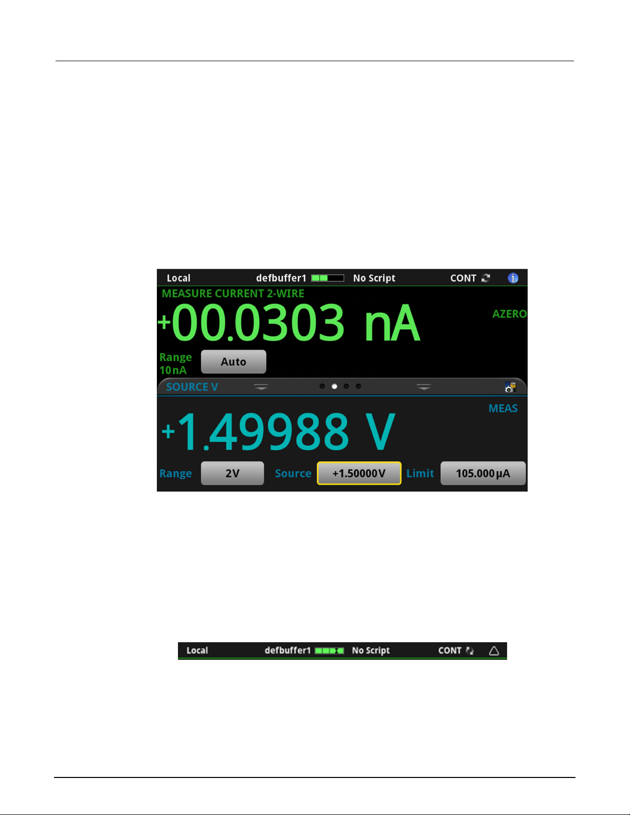
Model 2470
Instrument description
High Voltage SourceMeter Instrument Reference Manual Section 3:
Screen descriptions
The following topics describe the screens and options that you can view on the 2470
front-panel display.
Home screen
This is the default screen that you see whenever you turn the 2470 on or when you press the HOME
key. The options available on the home screen are described in the following topics.
Figure 31: 2470 home screen
Status and event indicators
The indicators at the top of the home screen contain information about instrument settings and states.
Some of the indicators also provide access to inst rument settings.
Select an indicator to get more information about the present state of the instrument. You can also
select the indicators by turning the navigation control to select an indicator and then pressing ENTER.
Figure 32: Home screen status bar
2470-901-01 Rev. B / September 2019 3-9

Section
Reference Manual
GPIB
Instrument is communicating through a GPIB interface
Local
Instrument is controlled from the front panel
Slave
Instrument is a subordinate in a T S P-Link system
TCPIP
Instrument is communicating through a LAN interface
Telnet
Instrument is communicating through Telnet
TSP-Link
Instrument is communicating through TSP-Link
USBTMC
Instrument is communicating through a USB interface
VXI-11
Instrument is communicating through an ethernet interface using the VXI-11 TCP/IP
instrument protocol
3: Instrument description Model 2470 High Voltage SourceMeter Ins trument
Communications indicator
The communications indicator displays the type of communications the instrument is using. Select the
indicator to display the present communications settings. Select Change Settings at the bottom of
the dialog box to open the System Communications screen, where you can change the settings.
Refer to Remote communications interfaces (on page 2-7
) for detail on the options that are available.
Figure 33: Communications indicator expanded
Indicator Instrument communication
Communications activity indicator
The activity indicator is located to the right of t he communi cations indicator. When the instrument is
communicating with a remote interface, the up and down arrows flash.
Figure 34: Communications indicator
3-10 2470-901-01 Rev. B / September 2019

Model 2470
Instrument description
High Voltage SourceMeter Instrument Reference Manual Section 3:
If a service request has been generated, SRQ is displayed to the right of the up and down arrows. You
can instruct the instrument to generate a service request (SRQ) when one or more events or
conditions occur. This indicator stays on until the serial poll byte is read or all the conditions that
caused SRQ are cleared.
Active buffer indicator
The Active Buffer indicator shows the name of the act ive reading buffer. Select the indicator to open a
menu of available buffers. Select a buffer name in the list to make it the active reading buffer. The
name of the new active reading buffer is updated in t he indi cator bar.
The green bar next to the buffer name indicates how f ul l t he buf fer is.
To create a new buffer, select Create New. The new buffer is automatically assigned to be the
active buffer.
Figure 35: Active buffer indicator menu
Active script indicator
This indicator shows script activity and allow s y ou to control script action from the home screen.
If there is no script activity, the indicator displays "No Script."
You can select the indicator to display a menu of av ai l abl e scripts. Select a script name to run that
script. You are prompted to confirm that you want to run the script .
If a script is running from the instrument or the USB flash d rive, the name of the script is displayed. If
a script from TSP is running, TSP_Script is displayed. I f you select the indicator, you are prompted
to abort the running script.
If the instrument is recording a macro script, "Recording" is displayed. You can select the indicator to
select an option to stop or cancel recording.
2470-901-01 Rev. B / September 2019 3-11

Section
Reference Manual
CONT
Continuous measurement: The instrument is making measurements
continuously.
IDLE
Trigger model measurement method. The trigger model is not running.
INACT
The trigger model is inactive. This occurs when the trigger model cannot run,
such as when the count is more than the reading buffer capacity.
MAN
Manual trigger mode: Press the front-panel TRIGGER key to initiate a single
measurement.
RUN
Trigger model measurement method. The instrument is running the pres ently
selected trigger model.
WAIT
Trigger model measurement method. The trigger model is waiting on an e v ent.
3: Instrument description Model 2470 High Voltage SourceMeter I nstrument
Measurement method indicator
Located to the right of the active script indicator, this indicator shows the active measurement method.
Select the indicator to open a menu. Select one of the buttons on the menu to change the
measurement method or initiate or abort the trigge r model. In the figure below, Continuous
Measurement is the present measurement m ethod.
Figure 36: 2470 active script indicator
Figure 37: Measurement method indicator
Indicator Meaning
3-12 2470-901-01 Rev. B / September 2019

Model 2470
Instrument description
An empty triangle means that no ne w event s were logged in the event log since the las t time you viewed
the event log.
A blue circle means that an informational event message was logged. T he m essage is for information
it also includes commands.
A yellow triangle means that a warni ng event message was logged. This messag e i ndicates that a
A red triangle means that an error event message was logged. When an error occurs , the requested
High Voltage SourceMeter Instrument Reference Manual Section 3:
System event indicator
On the right side of the instrument status indicator bar, this indicator changes based on the type of
event that has been logged.
Select the indicator to open a message screen with a brief description of the error, warning, or event.
Select the Event Log button to open the System Events tab of the event log, which you can use to
access detailed descriptions of the events. F or more information about the Event Log, see
event log (on page 3-50).
Using the
Figure 38: Error and message indicator
The following table describes the icons.
Icon Description
only. This indicates status changes or information that may be helpfu l. If the Log Command option is on,
change occurred that could affect operation.
change is not implemented.
2470-901-01 Rev. B / September 2019 3-13
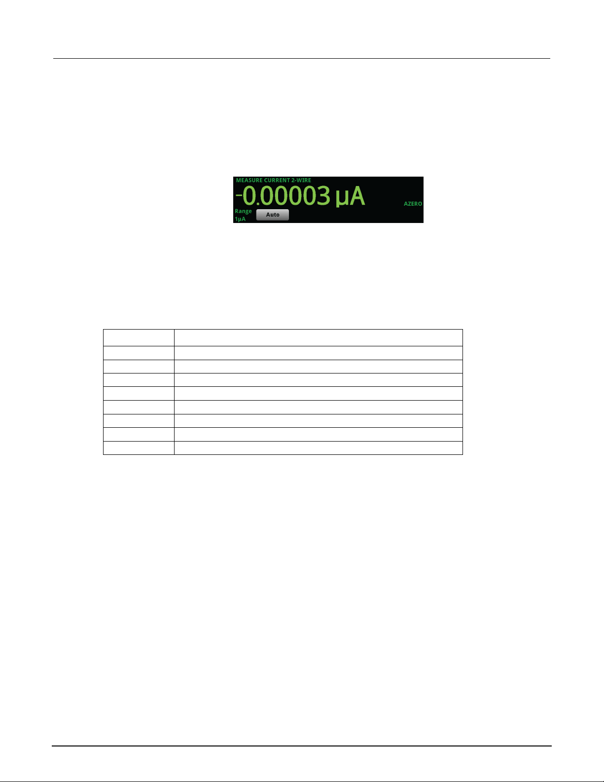
Section
Reference Manual
AZERO
Instrument automatically retrieves reference values
FILT
A filter is applied to the measurement
L1FAIL
Limit test one is enabled and measurem ent failed
L1PASS
Limit test one is enabled and measurem ent passed
L2FAIL
Limit test two is enabled and measurem ent failed
L2PASS
Limit test two is enabled and measurem ent passed
MATH
A percent, mx+b, or reciprocal calc ulation is applied
REL
Relative offset is applied
3: Instrument description Model 2470 High Voltage SourceMeter Ins trument
Measure view area
The Measure view area of the home screen displays the value of the present measurement and other
measurement information.
The Range button in the Measure area displays the presently selected measure range. Select the
button to change the range. If the Range label is yellow, the instrument is limiting the range.
The indicators on the right edge of the Measure vi ew area show any measure settings that affect the
displayed measurement value. The indicators and what they mean are defined in the following table.
Indicator Meaning
Figure 39: MEASURE area of the home screen
Swipe screens
The 2470 touchscreen display has multiple s cr eens that you can access by swiping left or right on the
lower half of the display. The options available in the swipe screens are described in the
following topics.
3-14 2470-901-01 Rev. B / September 2019
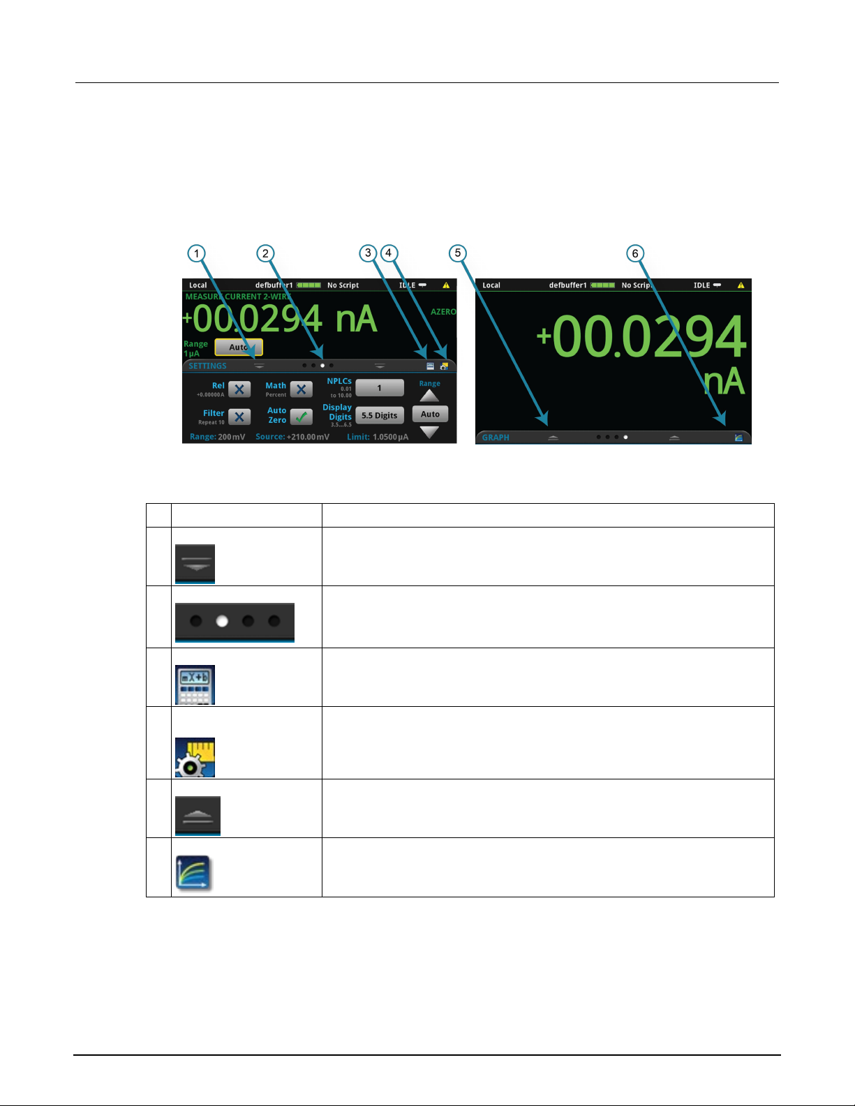
Model 2470
Instrument description
1
Minimize indicator
You can swipe down to minimize the swipe screens.
Each circle represents one swipe screen. As you swipe right or left, a different
3
Calculations shortcut
Select to open the CALCULATION SETTINGS menu.
4
Measure Settings
Select to open the MEASURE SETT INGS menu for the selected function.
5
Restore indicator
Indicates that you can swipe up to dis play the swipe screen.
6
Graph shortcut
Select to open the Graph screen.
High Voltage SourceMeter Instrument Reference Manual Section 3:
Swipe screen heading bar
The heading bar of the swipe screen contains the following options.
Figure 40: Swipe screens, maximized and mini mi zed
# Screen element Description
2 Swipe screen indicator
circle changes color, indicatin g where you are in the screen sequence. Select a
circle to move the swipe screen without swiping.
shortcut
2470-901-01 Rev. B / September 2019 3-15

Section
Reference Manual
3: Instrument description Model 2470 High Voltage SourceMeter Ins trument
SOURCE swipe screen
The SOURCE swipe screen shows the present value of the source and the set values for source,
source range, and source limit. You can change the set values from the front panel by selecting the
buttons on this screen.
Source function indicators on the right side of t he sc reen signify settings that affect the displayed
source value:
• MEAS: Source readback is on and the value shown is the measured value of the source.
• PROG: Source readback is off and the value shown is the programmed sou rce value. If the
output is off, the displayed source value is replaced with Output Off.
Figure 41: SOURCE swipe screen
When Limit label is shown in yellow, the instrument i s limiting the source.
The present value is updated continuously whe n the measurement method is set to Continuous.
When the measurement method is set to Manual T rigger Mode or Initiate Trigger Model, the value is
updated when the next measurement occurs. Ref er t o Source limits for more information.
The icon on the right side of the swipe screen headi ng bar is a shortcut to the full SOURCE
SETTINGS menu.
SETTINGS swipe screen
The SETTINGS swipe screen gives you front-panel access to some instrument settings. It shows you
the present settings and allows you to change, enable, or disable them quickly.
Figure 42: SETTINGS swipe screen
To disable or enable a setting, select the box next to the setting so that it shows an X (disabled) or a
check mark (enabled).
The icons on the right side of the swipe screen heading bar are shortcuts to the CALCULATIONS
SETTINGS and MEASURE SETTINGS menus.
For descriptions of the settings, use the navi gation control to select the button, then press the
HELP key.
3-16 2470-901-01 Rev. B / September 2019
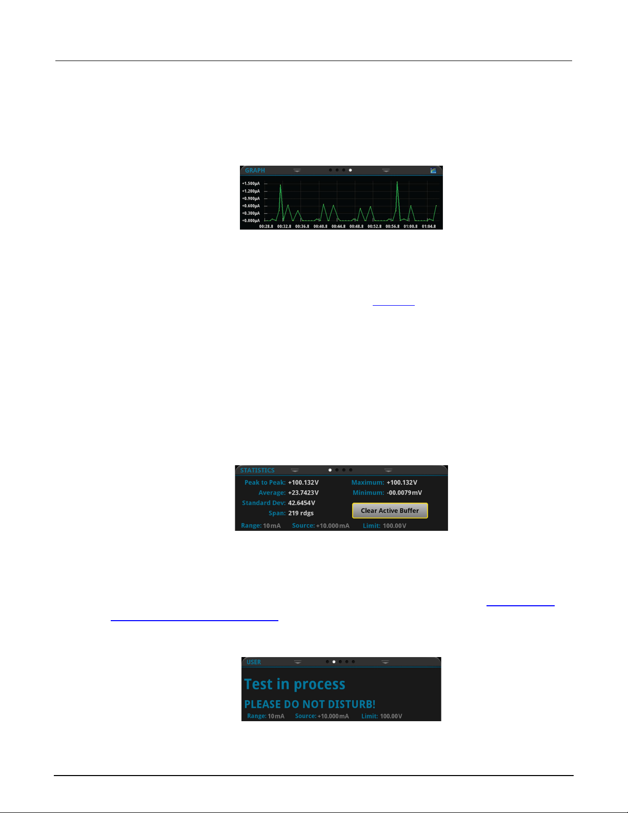
Model 2470
Instrument description
High Voltage SourceMeter Instrument Reference Manual Section 3:
GRAPH swipe screen
The GRAPH swipe screen shows a graphical representation of the readings in the presently selected
reading buffer.
To view the graph on the full screen and to access grap h set tings, select the graph icon on the right
side of the swipe screen header. You can also open the full-function Graph screen by pressing the
MENU key and selecting Graph under Views.
Figure 43: GRAPH swipe screen
For more information about graphing measurements, see Graphing (on page 7-1
).
STATISTICS swipe screen
The STATISTICS swipe screen contains informati on about the readings in the active reading buffer.
When the reading buffer is configured to fill cont i nuously and overwrite old data with new data, the
buffer statistics include the data that was overwrit ten. To get statistics that do not include data that
has been overwritten, define a large buffer size that will accommodate the number of readings you
will make. You can use the Clear Active Buffer butto n on this screen to clear the data from the active
reading buffer.
Figure 44: STATISTICS swipe screen
USER swipe screen
If you program custom text, it is displayed on the USE R swipe screen. For example, you can program
the 2470 to show that a test is in process. This swipe sc reen is only displayed if custom text has been
defined. For details about using remote command s t o program the display, refer to
message for the USER swipe screen (on page 3-42).
Customizing a
Figure 45: USER swipe screen
2470-901-01 Rev. B / September 2019 3-17
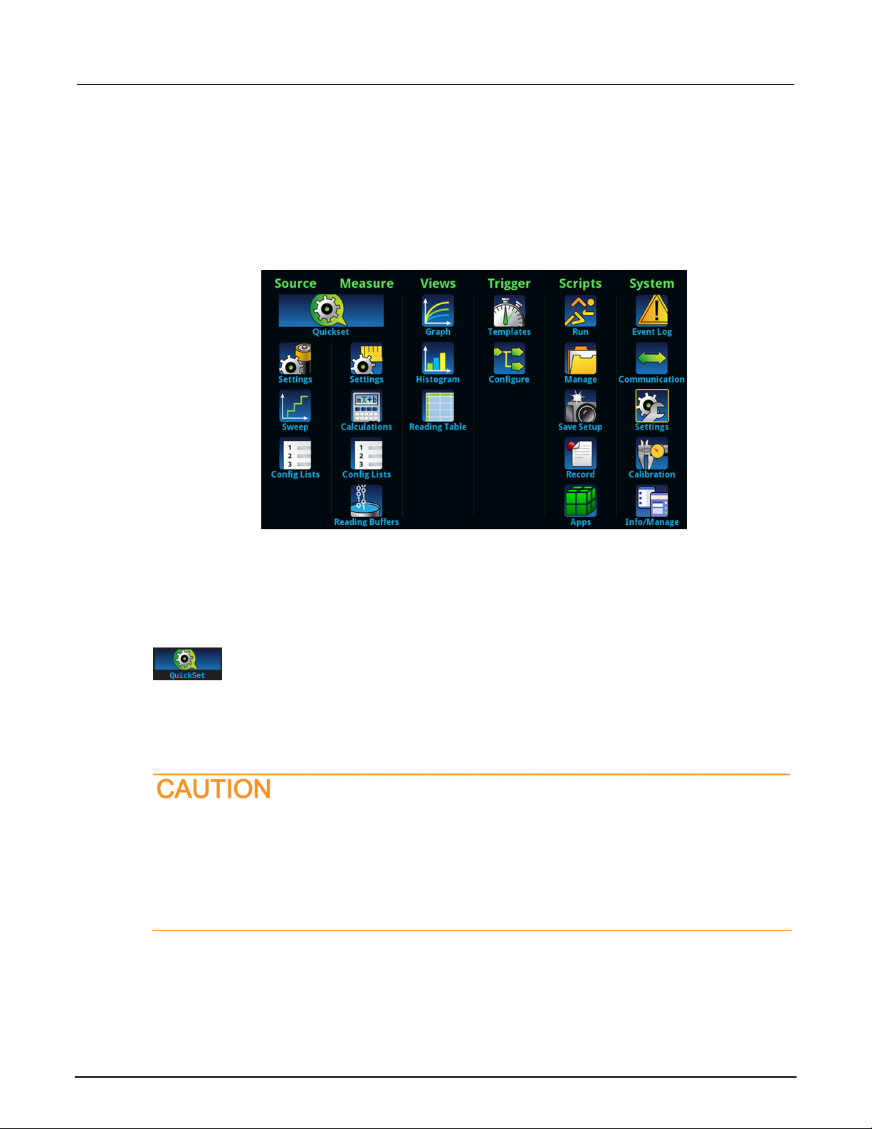
Section
Reference Manual
The QuickSet menu, which is centered u nder Source and Measure on the main
Select Quick Setups that provide ins trument-type emulation
3: Instrument description Model 2470 High Voltage SourceMeter Instrument
Menu overview
To access the main menu, press the MENU key on the 2470 front panel. The figure below shows the
organization of the main menu.
Figure 46: 2470 main menu
The main menu includes submenus that are labeled in green across the top of the display. Selecting
an option in a submenu opens an interactive screen.
QuickSet menu
menu, allows you to:
Select predefined setups for the sour ce and measure functions
Use the Performance slider to adjust for performance (resolution versus
When you select a Quick Setup, the instrument turns the output on. Carefully consider and
configure the appropriate output-off state, source, and limits before connecting the 2470 to a
device that can deliver energy, such as other vo ltage sources, batteries, capacitors, or solar
cells. Configure the settings that are recommended for the instrument before making
connections to the device. Failure to consider the output-off state, source, an d limits may
result in damage to the instrument or to the device under test (DUT).
speed)
3-18 2470-901-01 Rev. B / September 2019

Model 2470
Instrument description
You can change the following settings by pressing the MENU key and selecting S ource Settings.
Set the source range for the selected s our ce function. For more information, see
Source range (on page 4-39).
Select from Hi Impedance, Normal, Zero, and Guard output-off states. For more
information, see Output-off state (on page 4-16).
Set the overvoltage protection s etting of the source output to restrict the maximum
protection (on page 4-35).
more information, see Using the interlock (on page 4-3).
Turn on this setting to minimize overshoot, ringing, and instability whe n measuring low
operation (on page 5-23).
Turn on this setting to have the instrum ent record and display the actual value of the
readback (on page 4-45).
(on page 4-47).
High Voltage SourceMeter Instrument Reference Manual Section 3:
When you adjust the Performance slider, the i nstrument adjusts settings based on where you position
the slider. As you increase speed, you lower the amount of resolution. As you increase resolution, you
decrease the reading speed. The settings that the instrument adjusts include autozero, autodelay and
filter settings, display digits, NPLC, and source readback. These settings take effect the next time the
output is turned on and measurements are made.
When you select a Quick Setup, the home screen is di splay ed so you can see the readings
generated by the Quick Setup.
Source menu
The menus organized under Source in the main me nu allow you to select, configure, and perform
source and sweep operations from the front panel. The following topics describe the settings that are
available on these screens.
Source Settings menu
Setting Description
Range
Output Off
Overvoltage
Protection Limit
Interlock
High Capacitance
Source Readback
Source Delay
voltage level that the instrument can source. For more information, see Overvoltage
Determines if the output can be turned on when the interlock is not engaged. For
current while driving a capacitive load. For more information, see High-capacitance
source, instead of the programmed value. Using source readback result s in more
accurate measurements, at the cost of a reduction in measurement speed. Turn off
this setting to increase measurement speed. For more information, see Source
Set a delay for the selected source func tion. This delay is in addition to nor m al s ettling
times. Select Auto Delay to have the instrument autom atically set the delay or select
Specify Delay to enter a value. For more information, see Setting the sour c e delay
2470-901-01 Rev. B / September 2019 3-19
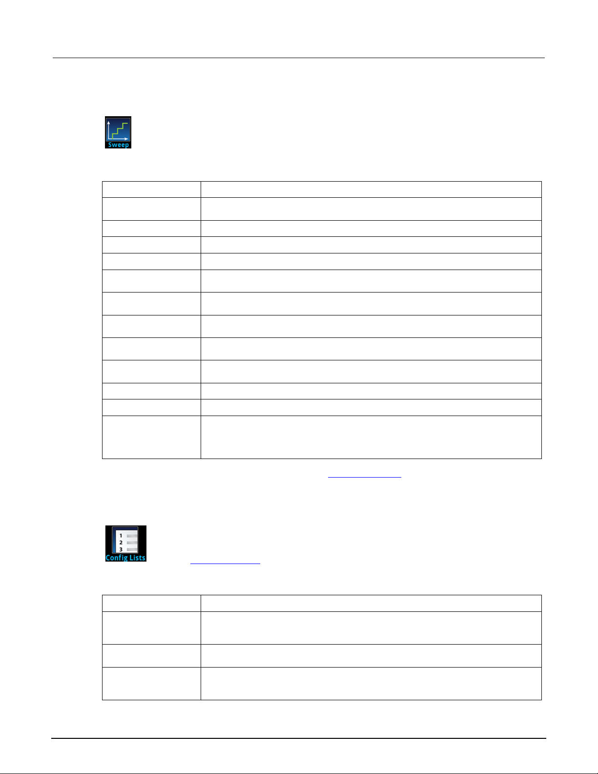
Section
Reference Manual
This menu allows you to set up a sweep and generate a source configuration list. It also builds a
Select to create a source configurat ion list and trigger model using the settings on this
menu.
Select the type of sweep: Linear, logarithmic, linear dual, or logarithmic dual.
Set the sweep voltage or current level at which the sweep starts.
Set the sweep voltage or current valu e at which the sweep stops.
Set this to Number of Points or Step Size. If you select Step Size, the instrum ent sets
the number of steps based on the step siz e.
When the Sweep Definition is set to Step Size, this sets the size of the steps that the
instrument uses to calculate the points for the sweep.
When the Sweep Definition is set to Number of Points, you can set the number of
points for the sweep.
set a specific delay from 0 to 9999.999 s.
Specifies the number of times to run the sweep; you can set it to run infinitely or a
specific number of times.
Specifies the source limit value for the sweep.
Enable or disable aborting a swee p when it reaches the programmed limi t.
Select Auto to automatically set the most sensitive source range f or each source level
the source remain on the range that is s et when the sweep is started.
This menu allows you to select an existing source configuration list, creat e a new list, load
lists, see Configuration lists (on page 4-82).
Saves the present instrument set tings to an index at the end of the selected
the end of the list or overwrite the set tings at the selected index.
Displayed if no source configuration lists have been created. Adds a s ource
configuration list.
Displays the details of the selected configuration index. Details inc lude settings such
displayed list to view additional settings.
3: Instrument description Model 2470 High Voltage SourceMeter Ins trument
Source Sweep menu
trigger model for the sweep.
Setting Description
Generate
Sweep Type
Start
Stop
Definition
Step
Points
Source Delay
Count
Source Limit
Abort on Limit
Source Ranging
For more information about setting up sweeps, see Sweep operation (on page 4-54).
Source Config Lists menu
configuration settings to and from the instrument, delete a configuration index, and view the
settings of a point in a source configuration list. For more information about using configuration
Setting Description
Add Settings
The delay time between measurement points. You can select an automatic del ay or
in the sweep. Select Best Fixed to have the instrument select a single fixed source
range that will accommodate all the source levels in the sweep. Select Fixed to have
configuration list. If an index is s el ec ted, you are prompted to append the settings to
Create New
Index Details
3-20 2470-901-01 Rev. B / September 2019
as function, level, protection limit, source readback, and dela y. You can scroll the

Model 2470
ent description
Opens a number pad that you can use to select an index.
Lists the last index in the selected c onfiguration list.
Restores the instrument to the settings stored in the selected configuration list index.
Displays a list of available source configuration lists from which you can c hoose.
This menu contains settings for t he presently selected measure function, which is identified by an
Set the Auto Range Low Limit to prevent the instrument from selecting a range that is
Determines if the instrument restores the measure range to match the lim it range after
making a measurement. Refer to Source limits for additional information.
Set Auto Zero to On to set the instrument s o that it periodically gets new
measurement accuracy but may slow measurement time.
Sets the number of readings that are processed when a measurement is requested.
Sets the number of digits that are disp l ayed for front-panel readings. It does not affect
accuracy or speed. Refer to Setting the number of displayed digits (on page 3-40).
Set the amount of time that the input sign al is measured. Lower NPLC settings result
reading noise, but slower reading rates.
The offset compensation setting is only available when the instrument is set to
low-resistance measurement accuracy.
Set the measure range for the presently selected measure function. You can select
sourcing one type of measurement and measuring another.
Select 2-wire (local) or 4-wire (remote) sense mode. Us e 2-wire sense if the error
measurement accuracy, use 4-wire sense.
High Voltage SourceMeter Instrument Reference Manual Section 3: Instrum
Setting Description
Jump to Index
Last Index
Recall Index
Remove Index
Select
Measure menu
The Measure menus allow you to select, configure, and perform measure operations from the front
panel. The following topics describe the settings that are available on these screens.
Measure Settings menu
indicator in the upper right corner of the menu. Select the function indicat or to change the source and
measure function.
Deletes a configuration list index f rom the selected configuration lis t.
Setting Description
Auto Range Low
Limit
Auto Range Rebound
Auto Zero
Count
Display Digits
NPLC
Offset Compensation
Range
Sense
lower than appropriate for your application.
measurements of its internal groun d and voltage reference. This set ting increases
in faster reading rates, but increased noise. Higher NPLC settings result in lower
measure resistance (SVMR(Ω) or SIMR(Ω)). Turn this setting on to improve
automatic or a specific range. You can only select a measure range if you ar e
contributed by test lead IR drop is acc eptable. For more accurate voltage source and
2470-901-01 Rev. B / September 2019 3-21

Section
Reference Manual
Use the relative offset feature to subtract a set value or a baseline reading from
and the relative offset value.
Sets the relative offset value to be applied to measurements.
This sets the number of measurements that are averaged when filtering is enabled.
Enables or disables the averaging filter for measurements of the selected function.
Selects the type of averaging filter that is used for the selected measure f unction
the data out of the stack before avera ging a new set of measurements.
Displays the settings that are available for the averaging filter.
This setting enables or disables math operations. When this is on, the math operation
specified by Math Format is applied to the measurement.
Defines the constant for the off set factor.
When Math is enabled, you can specify which math operation is performed on
applied).
Displays the settings that are available for the math functions.
When the Math State is set to On, this set ting specifies the reference used when t he
math operation is set to percent; the range is −1e12 to +1e12.
3: Instrument description Model 2470 High Voltage SourceMeter Ins trument
Measure Calculations menu
The Calculations menu contains settings that specify the way measurement information is
processed and returned.
Relative offset
Setting Description
Rel
Rel Value
measurement readings. When you enable relative offset, all subsequ ent
measurements are displayed as t he difference between the actual measured value
Filter
Setting Description
Count
Filter
Type
Settings
when the measurement filter is enabled.
Select the moving average filter to continuously add measurements to t he s tack on a
first-in, first-out basis, replacing the oldest measurement in the stack with a new
measurement.
Select the repeating average filter to average a set of measurements and then flush
Math
Math
Setting Description
b(Offset)
m(Scalar)
Math Format
Defines the constant for the scale factor.
measurements. You can choose one of t he following math operations:
mx+b: Manipulate normal display readings by adjus ting the m and b factors.
Percent: Specify a constant that is applied to the measurement and displ ay
readings as percentages.
Reciprocal: The reciprocal math operation displays measurement v al ues as
reciprocals. The displayed val ue is 1/X, where X is the measurement value (if
relative offset is being used, this i s the measured value with relative offs et
3-22 2470-901-01 Rev. B / September 2019
Settings
Zero Reference
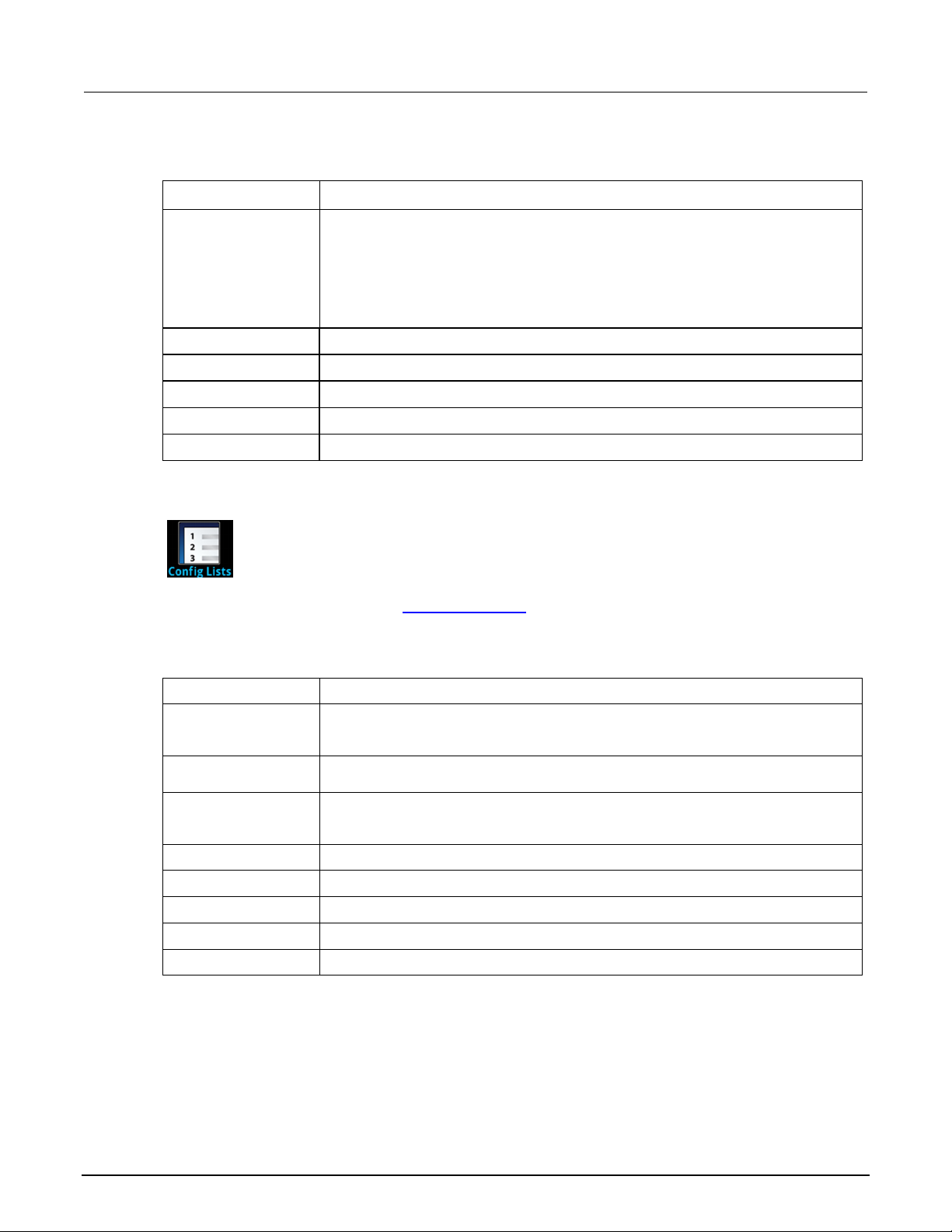
Model 2470
Instrument description
These settings enable or disable lim it testing. The Limit options allow you to do
outside these limits, the test fails. If a measurement is in the limits, it passes.
This determines if the instrument beeper sounds when a limit test passes or fails.
Specifies whether the high and low limits should be cleared automatical ly.
The Limit High Level specifies the upper limit for a limit test.
The Low Value specifies the lower limit for limit tests.
Displays the settings that are available for the limit functions.
If no index is selected, saves the present instrument settings to an ind ex at the end of
settings to the end of the list or overwrite the settings at the selected in dex.
This option is displayed if no measure configuration lists have been cre ated. When
select, it adds a measure configuration list.
Displays the details of the selected configuration index. Details inc lude settings such
view additional settings.
Opens a number pad that you can use to select an index.
Lists the last index in the selected configuration list.
Restores the instrument to the settings stored in the selected configuration list index.
Displays a list of available measure configuration lists from which yo u can choose.
High Voltage SourceMeter Instrument Reference Manual Section 3:
Limit
Setting Description
Limit 1 and Limit 2
Audible
Auto Clear
High Value
Low Value
Settings
Measure Config Lists menu
The Config Lists menu allows you t o select an existing measure configuration list,
create a new list, load configuration settings to and from the instrument, and view the
settings of an index in a configuration list. For m ore information about using
configuration lists, see Configuration lists (on page 4-82
pass-or-fail limit testing using the front panel of the instrument. When you do a limit
test, the home screen displays the pas s or fail result of the test.
Limit State enables or disables a l imit test for the selected measurem ent function.
When testing is enabled, limit test ing occurs on each measurement. Limit testing
compares the measurements to the high and low limit values. If a measurement is
).
Setting Description
Add Settings
the selected configuration list. If an index is selected, you are prom pted to append the
Create New
Index Details
as function, value, delay, calc ulations, and range. You can scroll the d isplayed list to
Jump to Index
Last Index
Recall Index
Remove Index
Select
Deletes a configuration list index f rom the selected configuration lis t.
2470-901-01 Rev. B / September 2019 3-23

Section
Manual
The percentage of data that is presently in the buffer.
Selects an existing buffer to config ure. Includes the Create New option, which allows
you to create a new buffer.
Sets the maximum number of readings that the buffer can store. Note that when you
change the capacity of a buffer, the r eadings in that buffer are cleared.
Clears data from the selected buffer . You can also press the MENU and EXIT keys
simultaneously to clear the acti v e buffer.
Deletes the selected buffer.
Continuous: Fills the buffer continuously and overwrites old data when the buffer
Once: Stops collecting data whe n the buffer is full (no data is overwritten).
Makes the selected buffer the active reading buffer.
Saves the data in the buffer to a CSV f i le, which can be opened by a spreadsheet
Defines the amount and type of data the buffer stores. Only available when creating a
Full: Store the same information as standard, plus additional information.
3: Instrument description Model 2470 High Voltage SourceMeter Ins trument Reference
Measure Reading Buffers menu
The Reading Buffers menu allows you to view the list of existing reading buffers and select
one to be the active buffer. You can also create, save, delete, resize, and clear buffers from
this screen.
To create a new reading buffer, select Buffer and select Create New. The new buffer is automatically
set to be the active buffer.
Setting Description
Amount Filled
Buffer
Capacity
Clear
Delete
Fill Mode
is full.
Make Active
Save to USB
Style
program. A USB flash drive must be present in the front-panel USB port before you
select Save to USB.
new buffer.
Standard: Store readings with full accurac y with formatting.
Compact: Store readings with reduc ed accuracy (6.5 digits) with no format ting
information, 1 μs accurate timestamp.
The maximum readings represent the highest possible limits and may vary depending on memory
usage, reading buffer style, or other reading buffers.
3-24 2470-901-01 Rev. B / September 2019
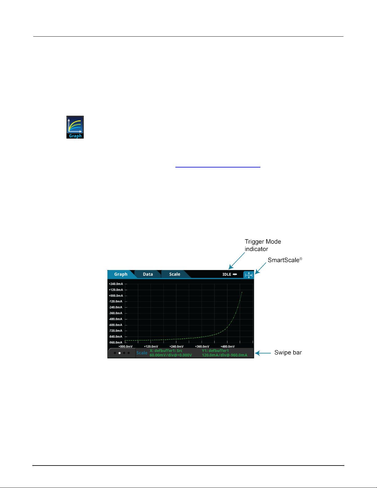
Model 2470
Instrument description
High Voltage SourceMeter Instrument Reference Manual Section 3:
Views menu
The menus under Views in the main menu allow you t o select, configure, and view data from measure
operations on the 2470. The following topics describe the settings that are available on
these screens.
Views Graph menu
The Graph menu opens a screen that displays a graph of the measurements as traces in
selected reading buffers. It also contains tabs t hat you use to customize the graph display.
You can also select the trigger mode and initiate the trigger model from this screen. Select
the measurement method indicator in the upper right corner of the screen and select the
measurement method. Refer to Measurement m ethod indicator (on page 3-12
Graph tab
The Graph tab graphs readings as they are made by t he i nstrument. Settings you make on the Data,
Scale, and Trigger tabs affect how readings appear on this screen. You can also select the number of
traces that are displayed.
) for details.
Figure 47: Graph tab
You can pinch to zoom in the graph view. You can also swipe the graph to the left or right. When you
adjust the view, the SmartScale
®
feature is turned off. To turn SmartScale bac k on, select the icon in
the upper right of the Graph tab. When SmartScale is on, the instrument determines the best way to
scale data based on the data and the instrument configuration (such as the measure count).
The values on the x and y axes show the values set in the Scale t ab. The information at the bottom of
the Graph tab contains a legend of the active axis and scale settings for the graph. You can swipe the
legend to view buffer statistics and readings at t he cursors. If the buffer type is set to full and contains
extra values the statistics are shown as Not Appli cable.
2470-901-01 Rev. B / September 2019 3-25

Section
Reference Manual
Selects the reading buffers that supply the data for the traces on the G raph tab. You
each. Colors are automatically ass i gned to the traces and cannot be changed.
Clears data from the selected buffer . To clear the active buffer, you can press the
MENU and EXIT keys simultaneously.
The drawing style determines how data is represented when there are many data
solid lines.
Sets the data to be plotted on the x-axis. You can select Scatter/IV or Time.
Removes the trace that is selected i n the Traces list. This removes the trace from
the display.
Displays the names of the reading buffers that contain the data for the tr aces that are
the active buffer to the list of traces, select Add and select the trace labeled Active.
3: Instrument description Model 2470 High Voltage SourceMeter Ins trument
Data tab
The Data tab allows you to select the reading buffe r t hat provides the data that is displayed on the
Graph tab. You can select up to four buffers. The data from each buffer is shown as a separate trace
on the Graph tab. You can also select the type of dra wing style that is used on the graph.
Setting Description
Add
can select up to 20 reading buffers and specify the buffer element for the y-axis for
Clear Buffer
Draw Style
points. You can select Line, Mark er , or Both.
When Line is selected, the data points ar e connected with solid lines. When Mar k er is
selected, the individual data point s are shown with no connecting lines. W hen both
are selected, the individual data points are shown and the points are connec ted with
Graph Type
Remove
Traces
displayed on the Graph tab. If no buffer i s selected, the active buffer is used.
You can select up to 20 buffers. The dat a from each buffer is displayed as a separat e
trace on the graph.
The active buffer contains the data that is displayed on the home screen and where
readings are stored when Continuous M easurement is selected or a manual trigger is
generated.
When an active buffer is selected on the Data tab, that trace tracks the active buff er
instead of a specific buffer. If the active buffer changes, the data that is displayed
changes to match the new active buffer .
To remove the active buffer from the list of traces, select it and select Remove Trace.
This does not affect the active buffer that is selected on the home screen. T o restore
3-26 2470-901-01 Rev. B / September 2019

Model 2470
Instrument description
When multiple traces are selected, toggles between the available tr aces. Information
specific to the trace is shown in the same c olor as the trace.
Sets the first value that is visible o n the graph for the selected trace.
The method determines how data is scal ed and tracked on the Graph tab. You
Position on the Scale tab.
The scale method determines how data is scaled on the Graph tab.
Off: No automatic scaling.
Sets the scale format that is used on t he graph. Select Linear to increase the step
High Voltage SourceMeter Instrument Reference Manual Section 3:
Scale tab
The Scale tab contains settings that allow you to fine-t une the output on the Graph tab.
Setting Description
Trace
X-Axis and Y-Axis
Minimum Position
X-Axis and Y-Axis
Scale
X-Axis Method
Sets the reading value scale for each division.
can select:
SmartScale
the graph automatically, determ i ning the best scaling and tracking meth od
based on the data, reading groups, number of traces, and instrument
configuration. The scale is set to show the most relevant portion of the data that
is in the selected reading buffer.
®
: When the SmartScale feature is selected, the instrument scales
Show New Readings: The graph always displays the latest data on a
fixed scale.
Show Group of Readings: The graph displays a group of readings. A group is
automatically created when the measure count is set to more than 1.
Show All Readings: All data in the buffer is displayed on the graph.
Off: The graph is not automatically adjust ed. You can adjust the data manually
by swiping, pinching, and zooming. You can also set the Scale and Minimum
Y-Axis Method
If you are graphing one trace, you can sel ect:
SmartScale
to fit all the data that is in the selected reading buffer onto the screen. The
instrument determines the best scale based on the data.
®
: The instrument scales the graph autom atically. The scale is set
Autoscale Always: Continuously scales the y-axis of the trace so it fits the
entire height of the screen.
Autoscale Once: Scales the y-ax is of the trace once.
Off: No automatic scaling.
If you are graphing multiple traces, you can select:
SmartScale
determines the best scale and trac k i ng method based on the data, reading
groups, number of traces, and instr ument configuration.
®
: The instrument scales the graph autom atically. The instrument
Independent Autoscale: Scales the y-axis of the trace so it fits the entire
height of the screen.
Swim Lanes: Scales the y-axis of the tr ac es in equal, non-overlapping port ions
of the height of the screen.
Shared Autoscale: Accommodates the minimum and the maximum of all
traces.
Y-Axis Scale Format
size in even increments. Select Log to increase the step size exponentially.
2470-901-01 Rev. B / September 2019 3-27

Section
Reference Manual
Determines the event that is used to trigger measurements. You can select:
None: No trigger event.
The position marks the location in the reading buffer where the trigger will occur. The
until 100 percent of the buffer is f il led.
Specifies whether previously det ec ted trigger events are cleared. You can select:
not cleared.
When the source is set to Digital, TSP-Link, or External, this sets the type of edge that
generates a trigger. You can set it to Rising, Falling, or Either.
When the source is set to Digital, this selects the digital input line that generates the
trigger (1 to 6).
When the source is set to TSP-Link, this selects the TSP-Link input line that
generates the trigger (1 to 3).
Trigger tab
3: Instrument description Model 2470 High Voltage SourceMeter Ins trument
The Views Graph Trigger tab contains settings t hat define the trigger mode.
Setting Description
Source Event
Display TRIGGER Key: The trigger occurs when you press the TRIGGER key.
Digital Input Line: The trigger occurs when a pulse is detected from the digital
input line.
TSP-Link Input: The trigger occurs when a pulse is detected from a TSP-Link
input line.
Source Limit: The trigger occurs when the source attempts to exceed the
source limit.
Delay
Position
Trigger Clear
Edge
Digital In Line
TSP-Link Line
Views Histogram menu
The Histogram menu allows you to graph the distribution of measurement data in t he
selected reading buffer. It also contains tabs that you use to customize the histogram.
The delay time before each measurement (167 ns to 10 ks); default is 0 for no delay.
position is set as a percentage of the buffer capacity. The buffer captures
measurements until a trigger occurs. When the trigger occurs, the buffer retains the
percentage of readings specified by the position, then captures remaining readings
Enter: Previously detected trigger events are cleared.
Never: Any previously detected triggers are acted on immediately and
Histogram tab
The Histogram tab graphs readings as a bar graph of the data distribution into bins. Settings you
make on the Data and Scale tabs affect which data a re used and how data distributions appear on
this screen. You can change the scale of either axis on t he sc reen by dragging or pinching
the screen.
3-28 2470-901-01 Rev. B / September 2019

Model
2470 High Voltage SourceMeter I nstrument Reference Manual Section 3:
Instrument description
Selects the reading buffers that supply the data for the traces on the D ata tab.
Clears data from the selected buffer . To clear data from the active buffer, you can
press the MENU and EXIT keys.
The highest value of the data that is bin ned in the histogram. Data that is above this
level is binned in the high outlier bin.
The method of autoscaling to use:
Off: Turn off autoscaling.
The lowest value of the data that is binned in the histogram. Data that is bel ow this
The number of bins in the histogram.
Figure 48: 2470 Histogram
Data tab
The Data tab allows you to select which reading buff er provides the data that is binned on the
Histogram tab. You can also clear the data from the selected buffer.
Setting Description
Add Trace
Clear Buffer
Scale tab
The Scale tab allows you to set up boundaries, numb er of bi ns, and type of scaling used for
the histogram.
Setting Description
Maximum Boundary
Method
Minimum Boundary
Number of Bins
SmartScale
®
: Automatically select the most appropriate scaling method.
Auto Bin: Redistribute the data evenly in the bins based o n the present
minimum and maximum boundaries.
Fit: Adjust the y-axis scale so that the tops of all bins are visible
level is binned in the low outlier bin.
The histogram will create two outlier bins in addition to the bins you define. These
bins are used to collect data that is bel ow or above the defined minimum and
maximum boundaries.
2470-901-01 Rev. B / September 2019 3-29
Section
Reference Manual
Selects the reading buffer that c ontains the data you want to view. If Act ive is
is displayed.
Select a data point to open the Reading Details window for the selected data point.
The details describe the instrument settings when the data point was read.
Shows a small graph view of the data in the reading table. Touch a data point in the
Displays the data in the selected reading buffer. You can select a data point to display
additional detail about that data point.
Creates a trigger model that loads a so ur ce and measure configuration list. The lists
Reading Buffer (default defbuffer1)
3: Instrument description Model 2470 High Voltage SourceMeter Ins trument
Views Reading Table menu
This menu allows you to view data in the selected reading buffer.
Setting Description
Buffer
Reading Details
selected, the data from the reading b uffer that is presently storing readi ngs
Reading Preview
Graph
Table
graph to jump to that data point in the table.
Trigger menu
The menus under Trigger in the main menu allow you t o conf igure triggering operations from the 2470
front panel. The following topics describe the set t i ngs that are available on these screens.
Trigger Templates menu
The Templates menu allows you to choose from one of several preprogrammed trigger
models. When you select a template, settings you can specify for that template are
shown in the lower part of the screen.
You can also customize the templates from the front panel using the Configure menu under Trigger
on the main menu screen. For details, see Trigger Configure menu (on page 3-32
The table below describes the trigger-model templates and available user-specified settings and t hei r
default settings.
).
Setting Description
ConfigList
are iterated until every index in the c onfiguration list with fewer indexes has been
loaded. For example, if the measur e l ist has seven indexes and the source
configuration list has 10, it will i terate through seven indexes of the source list and all
of the measure list. However, if the source list has three indexes and the measure list
has five, it will iterate through three indexes of measure list and all of the indexes in
the source list. At each index when the output is turned on, a measurement is made
and the output is turned off.
Settings that you can change before generating the trigger model:
Measure Config List
Source Config List
Delay (default 0.001 s)
3-30 2470-901-01 Rev. B / September 2019

Model 2470
Instrument description
Creates a trigger model that makes continuous measurements for a specified amount
defbuffer1
Clears the present trigger model.
Creates a trigger model that success i vely measures components and com pares their
Creates a trigger model that waits on an input line, delays, makes a meas urement,
defbuffer1
Creates a trigger model that makes continuous measurements until a spe cified event
Trigger Clear (default Enter)
Creates a trigger model that sets up a loop that sets a delay, makes a measurem ent,
defbuffer1
Creates a trigger model that success i vely measures components and com pares their
readings to high or low limits to sort components.
High Voltage SourceMeter Instrument Reference Manual Section 3:
Setting Description
DurationLoop
of time.
Settings that you can change before generating the trigger model:
Duration (default 1.00 s)
Delay (default 0.001 s)
Reading Buffer (default
Empty
GradeBinning
readings to high or low limits to grade components.
LogicTrigger
and sends out a trigger on the output lin e a specified number of times.
Settings that you can change before generating the trigger model:
)
Input Line (default 1)
Output Line (default 2)
Count (default 10)
Delay (default 0.001 s)
Trigger Clear (default Never)
Reading Buffer (default
LoopUntilEvent
occurs. Settings that you can chan ge before generating the trigger model :
)
Source Event (default Trigger Key)
Position (default 50%)
Delay (default 0.001 s)
Reading Buffer (default defbuffer1)
SimpleLoop
and then repeats the loop the number of times you define in the Count parameter.
Settings that you can change before generating the trigger model:
Count (default 10)
Delay (default 0.001 s)
Reading Buffer (default
SortBinning
)
2470-901-01 Rev. B / September 2019 3-31
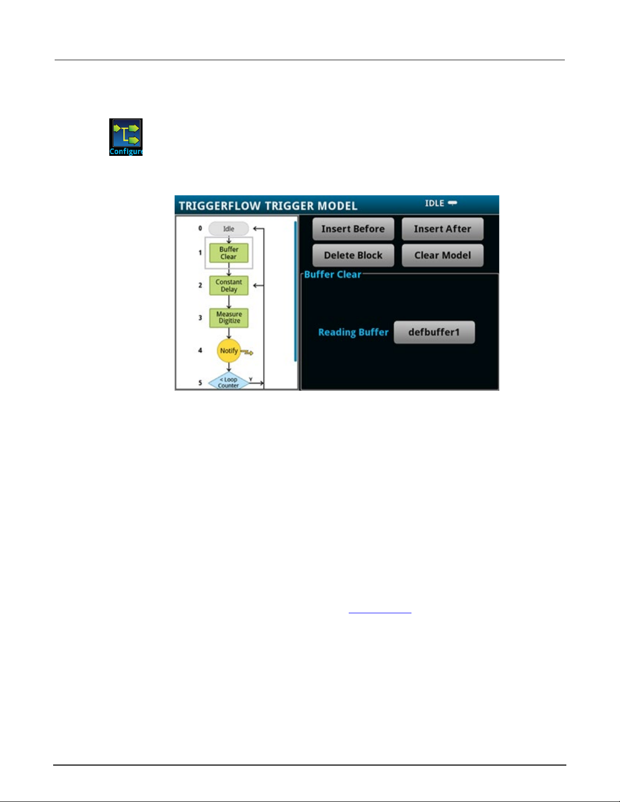
Section
Reference Manual
3: Instrument description Model 2470 High Voltage SourceMeter Ins trument
Trigger Configure menu
The Configure menu allows you to view and modify the structure and parameters of a
trigger model. You can also monitor trigger model operation.
Figure 49: TRIGGERFLOW TRIGGER MODEL screen
To see the parameters that you can change from the front panel, select a block in the trigger model
diagram. The available options change depending on the type of block you select.
From this screen, you can:
• Insert a new trigger block before or after the selected block
• Choose among several block types to add
• Edit an existing block
• Delete an existing block
• Remove all trigger blocks by selecting Clear Model
When you finish your changes to the trigger model, y ou can ini tiate the trigger model by pressing the
front-panel TRIGGER key.
For detailed information on the trigger model, ref er to Trigger model (on page 8-25
).
3-32 2470-901-01 Rev. B / September 2019
Model 2470
Instrument description
Displays a list of available script s that you can select. All scripts that are saved on the
2470 or are on a USB flash drive inserted into the instrument are listed.
Saves the selected script to a script that runs automatically when the inst rument is
autoexec
Runs the selected script immediately.
Copies a script from the instrument t o a U S B script. A USB flash drive must be
Copies a script from a USB flash drive to the instrument. A USB flash drive must be
inserted before you select this option.
Deletes the script that is selected.
High Voltage SourceMeter Instrument Reference Manual Section 3:
Scripts menu
The menus under Scripts in the main menu allow you to configure, run, and manage scripting
operations from the 2470 front panel. Scripts are blocks of commands that the instrument can run as
a group. The following topics describe the sett i ngs that are available on these screens.
Scripts are presented in alphabetic order. Scripts that are on a USB flash drive are presented after
scripts that are loaded on the instrument.
Scripts Run menu
The Run menu contains a list of scripts that you can select to run immediately. You can also
copy a script to a script that runs each time the instr ument power is turned on. You can
access scripts that are in the instrument or on a USB flash drive.
Setting Description
Available Scripts
Copy to Power Up
Run Selected
Scripts Manage menu
The Manage menu allows you to copy scripts t o and from the instrument and the USB
flash drive. You can also delete scripts from the instrument or USB flash drive.
Setting Description
>
<
Delete
For more information about using scripts with the 2470, see Fundamentals of scripting for TSP (on
page 13-4).
turned on. The script is saved with the sc ript name
inserted before you select this option.
.
2470-901-01 Rev. B / September 2019 3-33
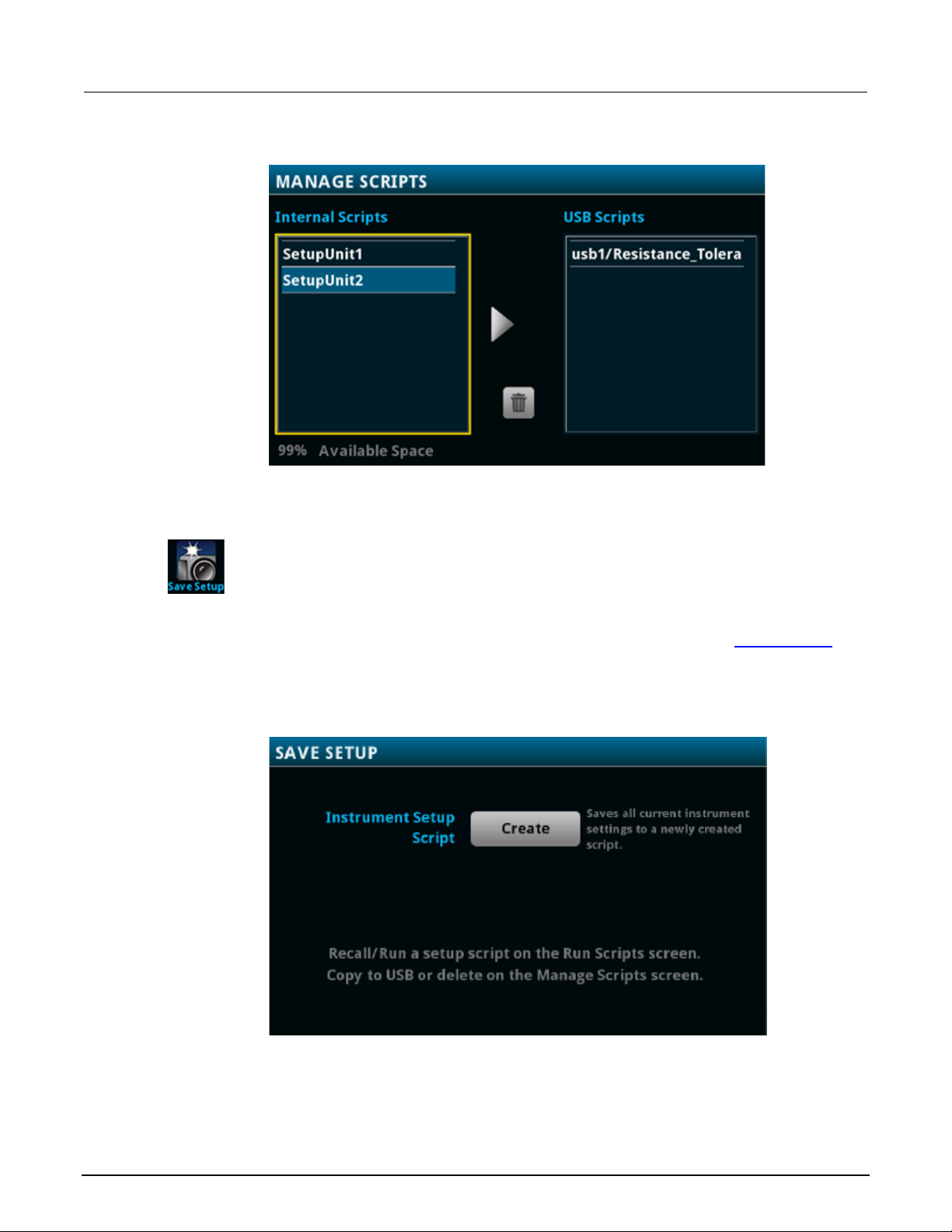
Section
Reference Manual
3: Instrument description Model 2470 High Voltage SourceMeter Ins trument
Scripts Save Setup menu
Figure 50: 2470 MANAGE SCRIPTS menu
The Save Setup menu allows you to save the present set tings and configuration lists of the
instrument into a configuration script. You can use this script to recall the settings. Graph
settings are not saved.
For more information about user configuration s cripts and setups, see Saving setups
page 3-45).
Figure 51: 2470 SAVE SETUP menu
(on
3-34 2470-901-01 Rev. B / September 2019
 Loading...