


Tektronyx
24XSAl2467
Option 10
Instrument Interfacing Guide
70-6282-00
0

-
.
<
. . .--..e
-m.-.. .
TEK . INTER-OFFICE COMlvllJNlCATlON
TO
Sohn Martin
94-540
.-
3:. ’ t
.
Juno 25, 1991
Frank Gray, SO-PAT
FWW
M3KC.T
GIDEP permit request
In response to
Government
Tektronix operator,
Tektronix, Inc. hereby grant6 such permission for distribution
of
such documents to any
in the Metrology Data Interchange Data Base
that
copyright notice and ownership statement exactly a-& it appears
in the original, together with the Legend "Reproduded with
pemieeion,a
aeon% 1[
all copies
This permission has been approved by the Intellectual
Industry
Committee of Tektronix
ded
to GIDEP to grovide’the requested permission.
the request
Exchange
service and
GTDEP
of the original work include the entire
to grant permission to
Pro
ram (GPDEP) to reproduce
nstruction manuals,
P
user that is a full participant
of
GIDEP provided
and
a
copy of this memo may
the
geG&dy
Group Pat&t Counsel Group Patent C&nsal v

Tektronjx
24XSAl2467
Option 10
Instrument Interfacing Guide
070-6282-00
Please check for change information at the rear
of this manual.
First Edition: September 1986
Last Revised: February 1988
_--... -. -- ------

Copyright 0 Tektronix, Inc. 1986. All rights reserved.
Tektronix products are covered by U.S. and foreign patents, issued and
pending. Information in this publication supercedes that in all previously
published material. Specifications and price change privileges reserved.
Printed in the U.S.A.
Tektronix, Inc., P.O. Box 1000, Wilsonville, OR 97070-1000
TEKTRONIX and TEK are registered trademarks of Tektronix, Inc.

.......................................................................................................... iv
Tables
Operators Safety Summary
Introduction
1
........................................................................
2 Measurement Capabilities and Ch8racteristics
Cursors..
Frequency and
Time Interval..
Repetitive Time intervals
Non-Repetitive Time Intervals..
Peak Amplitude.
Programming Techniques
3
4
Self-Contained Programs.. .....................................................................
Easy Programs
Full-Power Programs
System
Setting GPIB System Parameters.. .......................................................
Instrument Configuration
IBM PC/XT/AT Configuration
Program Considerations at Power-on.
................................................................................................. 2-l
..........................................................................
Period..
.........................................................................................
..................................................................................... 2-3
.......................................................................................
.......................................................................
.............................................................. 2-3
.............................................................................
Contigur8tion
.......................................................................
................................................................
.................................................. 4-5
Page
V
2-l
2-2
2-2
3-1
3-l
3-2
4-l
4-3
4-4
Communication Between Oscilloscope
5
Output Statements
Query Commands and Responses..
Input Statements.. ..................................................................................
Setup Transfers
Sending and Receiving ASCII Setups
Sending and Receiving Binary Setups.
SRQ and Event Codes
Interface Messages
Local Lockout
Remote Enable (REN). ...........................................................................
Go To Local (GTL)
My Listen Address and My Talk Addresses
Unlisten (UNL) and Untalk (UNT). ..........................................................
Interface Clear (IFC)
Device Clear (DCL).
24X5Al2467 Instrument Interfacing Guide
.................................................................................
.....................................................................................
.......................................................................... 5-5
................................................................................
(LLO)
..............................................................................
................................................................................. 5-7
............................................................................... 5-7
................................................................................
and
Controller
..................................................... 5-2
................................................... 5-4
.................................................
........................................ 5-7
5-1
5-3
5-3
5-5
56
5-6
5-7
5-7
5-8
i

Contwtta
Selected Device Clear (SDC). ................................................................ 5-8
Serial Poll Enable and Disable (SPE and SPD) .................................... 58
Command Handler ................................................................................. 5-8
Service-Request
GPIB Commands
Headers ..................................................................................................
Arguments.. ............................................................................................ 5-10
Command Separator.. ............................................................................ 5-l 1
Queries
Abbreviations ......................................................................................... 5-l 1
GPIB Commends
6
................................................................................................... 5-l 1
Message Terminator.. ............................................................................ 5-l 1
Numeric Arguments
Measurement Techniques
Introduction ............................................................................................ 7-1
Trigger Settings..
Measuring Time Intervals on Repetitive Signals.. ................................. 7-2
Measuring Single-Shot Time Intervals .................................................. 7-4
Measuring Peak Voltages.. .................................................................... 7-5
Measuring
Trigger Level
Programming
Rise and Fall Times ............................................................. 7-6
Pege
Handler ....................................................................... 5-S
................................................................................... 5-10
5-l 0
............................................................................... 5-l 2
.................................................................................... 7-1
Compensation..
Examples.. ....................................................................... 7-10
................................................................
7-10
ii 24X%/2467 Instrument Interfacing Guide

Page
A
Appendix
Programming Examples . . . . . . . . . . . . . . . . . . . . . . . . . . . . . .
A
Tektronix 4041 Program to Send Commands to the Oscilloscope
Tektronix 4041 Program to Calibrate Trigger Levels
for Transition
IBM PC/XT/AT Program to Calibrate Trigger Levels
for Transition Time . . . . . . . . . . . . . . . . . . . . . .,.............,.................................. .
HP 98Xx Program to Calibrate Trigger Levels
for Transition Time . . . . . . . . . . . . . . . . . . . . . . . .
Tektronix 4041 Subroutine to Measure
Frequency, Count, and Time
IBM PC/XT/AT Subroutine to Measure Frequency,
Count, and Time
Tektronix 4041 Subroutine to Measure Peak
Voltages . . . . . . . . . . . . . . . . . . . . . . . . . . . . . . . . . . . . . . . . . . . . . . . . . . . . . . . . . . . . . . . . . . . . . . . . . . . . . . . . . . . . . . . . . . . . . . .
IBM PC/XT/AT Subroutine to Measure Peak
Voltages. . . . . . . . . . . .
HP 98XX Subroutine to Measure Peak Voltages . . . . . . . . . . . . . . . . . . . . . . . . . . . . . .
B Appendix B
Status and Error Reporting _..........._........... . . . . . . . . . . . . . . . . . . . . . . . . . . . . . . . . . . . . . . . . . . . . . .
Appendix C
c
Message Command
Appendix D
D
Sweep Speed Command Considerations . .._._.............................................
. . . . . . . . . . . . . . . . . . . ..*..........................
Time . . . . . . . . . . . . . . . . . . . . . . . . . . . . . . . . . . . . . . . . . . . . . . . . . . . . . . . . . . . . . . . . . . . . . . . . . . . . . .
. . . . . . . . . . . . . . . . . . . . . . . . . . . . . . . . . . . . . . . . . . . . . .
. . . . . . . . , . . , , . . . . . . . . . . . . . . . . . . . . . . . . . . . . . . . . . . . . . .
. . . . . . . . . . . , . . . . . . . . . . . . . . . . . . . . . . . , . . . . . . . . . . . . . . . . . . . . . . . .
. . . . . . . . . . . . . . . . . . . . . . . . . . . . . . . . . . . . . . . . . . . . . . . . . . . . . . . . . . . . . . . . . . . .
. . . . . . . . . . . . . . . . . . . . . . . . . . . . . . . . . . . . . . . . . . . . . . . . . . . . . . . . . . . . . . . . . . . . . . . . . . . . . . . . . . . .
. . . . . . . . . . A-33
A-l
A-l
A-2
A-9
A-18
A-28
A-29
A32
A-85
B-l
C-l
D-l
E Appendix E
GPIB Command
Reference . . . . . . . . . . . . . . . . . . . . . . . . . . . . . . . . . . . . . . . . . . . . . . . . . . . . . . . . . . . . . . . . . . . . . . . . .
F Appendix F
LLMessage Command Character Translations ._........,............................... F-l
24X5A/2487 Instrument Interfacing Guide
E-l
iii

Tables
Table
Functional Enhancement Options .................................................................. l-l
l-1
5-l Command or Query Byte Counts..
Numeric Argument Format for GPfB Commands
5-2
6-l Vertical Commands
6-2 Horizontal Commands..
6-3 Trigger Commands..
Delay and Delta Commands.. ........................................................................
6-4
6-5 System Commands
GPIB Command Set for the TV Option.. ....................................................... 6-23
6-6
Counter/Timer/Trigger GPIB Commands ...................................................... 6-24
6-7
Word Recognizer GPIB Commands
6-6
GPIB Command Set for the DMM Option .................................................... 6-29
6-9
6-10 Calibration and Diagnostic Commands..
Delay Time and Delta-Delay Time ................................................................. 7-13
7-1
B-l Status Event and Error Categories
B-2 GPIB Status Codes ........................................................................................
C-l MESsage Command Character Translations..
Sweep Speecl Command Results.. ................................................................ D-2
D-l
GPIB Command Summary.. ........................................................................... E-l
E-l
F-l
LLMessage? Query Character Set (Code-Sequenced).
LLMessage Command Character Set .......................................................... F-l
F-2
........................................................................................ 6-1
..................................................................................
.......................................................................................
........................................................................................
................................................................
......................................... 5-l 2
..............................................................
....................................................... 6-33
............................................................... B-2
.............................................. c-2
................................ F-2
Page
5-4
z
6-11
6-13
6-28
B-3
0
24X5Al2467 Instrument Interfacing Guide

Operators Safety Summary
The general safety information in this part of the summary is for both operating
and servicing personnel. Specific warnings and cautions will be round
throughout the manual where
Terms
In This Manual
CAUTION statements identify conditions or practices that could result in
damage to the equipment or other property.
WARNING statements identify conditions or practices that could result in
personal injury or loss of life.
As Marked on Equipment
CAUTION indicates a personal injury hazard not immediately applicable as One
reads the markings, or a hazard to property, including the equipment itself.
DANGER indicates a personal injury hazard immediately applicable as one
reads the marking.
Symbols
In This Manual
they
apply and do
not
appear in this summary
A
As Marked on Equipment
A
24X5A/2467 Instrument interfacing Guide
information is to be found. For maximum input voltage see Table 6-l.
DANGER-High voltage.
Protective ground (earth) terminal.
!
ATTENTION-Refer to manual.
This symbol indicates where applicable cautionary or other
!
V

Operators Safety Summary
Power Source
This product is intended to operate from a power source that does not apply more
than 250 volts rms between the supply conductors or between either supply
conductor and ground. A protective ground connection by way of the grounding
conductor in the power cord is essential for safe operation.
Grounding the Product
This product is grounded through the grounding conductor of the power cord. To
avoid electrical shock, plug the power cord into a properly wired receptacle before
connecting to the product input or output terminals. A protective ground
connection by way of the grounding conductor in the power cord is essential for
safe operation.
Danger Arising From Loss of Ground
Upon loss of the protective-ground connection, all accessible conductive parts
(including knobs and controls that may appear to be insulating) can render an
electric shock.
Use the Proper Power Cord
Use only the power cord and connector specified for your product.
Use only a power cord that is in good condition.
For detailed information on power cords and connectors see Table 1-l.
Use the Proper Fuse
To avoid fire hazard, use only a fuse of the correct type, voltage rating and current
rating as specified in the parts list for your product.
Do Not Operate in Explosive Atmospheres
To avoid explosion, do not operate this product in an explosive atmosphere unless
it has been specifically certified for such operation.
Do Not Remove Covers or Panels
To avoid personal injury, do not remove the product covers or panels. Do not
operate the product without the covers and panels properly installed.
vi
24X5A/2467 Instrument Interfacing Guide

Introduction
The Tektronix 2445A, 2455A, 2465A, and 2467 Portable Oscilloscopes have raised
measurement capability and operator efficiency far above previous standards. These
qualities are enhanced by a family of Options. Options are available individually or in
Special Editions which combine them in synergistic packages.
Number
10
09/09
09
01
05
Functional Enhancement Options
Table l-l
Designation
IEEE-488 (GPIB)
Interface
Counter-Timer-Trigger
w-v
Word Recognizer (WR
Digital Multimeter
@MM)
TV/Video Analysis
System (TV)
Adapts the oscilloscope to measurement
systems. (Included in 2465A DV, 2465A
DM, 2465A CT.)
Measures frequency, period, or total;
enhances timing accuracy; delays trigger
by event count; triggers on signal
combinations. (Included in 2465A DV,
2465A Dfvl, 2465A CT.)
Triggers sweep or counter on 17-bit word.
(Included in 2465A DV. 2465A DM, 2465A
CT.)
Measures V,. V,,. A*, A,,, resistance,
continuity, temperature, dB. averages, and
changes, with 4 112 digits (included in
2465A DV, 2465A DM).
Triggers on selected video lines: clamps
‘back porch.” (Included in 2465A DV.)
Function
24X5A/2467 Instrument Interfacing Guide l-l

This Interfacing Guide shows how to use the 24X5A/2467 Oscilloscopes with
Option 10 in a GPIB system. It explains the instruments’ measurement capabilities,
how to set them up for GPIB operation, and how to communicate with the
oscilloscopes and their options with a system controller. Consult the instrument
operators manual for basic measurement techniques.
If your instrument is configured with at least the GPIB and CTT (Options 10 and 06
or Options 10 and 09), it can measure frequency, period, time interval, peak voltages,
rise and fall time, slew rate, duty factor, peak-to-peak voltage, frequency ratio, and
other signal parameters automatically. The DMM adds precise measurements of lowspeed signals to the possibilities for automation.
If your tests are not suited to automation, a measurement system can interact with
an operator through the instrument. The controller sets the scope to display a
waveform and the operator positions AV or At cursors to the points of interest. The
controller men logs the measurement or compares it to limits. In other applications.
the operator adjusts a circuit or device by looking at an automatically displayed
waveform. Cursors can indicate test limits or adjustment targets.
1-2
..x-_..- ..__ -..^.._ l.l-
24X5/\/2467 Instrument Interfacing Guide

Measurement Capabilities
and Characteris tics
cursors
For semiautomatic measurements, the cursors aid communication between the
system and the operator. An operator can align the cursors with specific waveform
features and the controller can assimilate the data. A controller can set the cursors
to nominal starting positions, close to the actual measurement or to limit positions
within which a waveform should fall.
The cursors give excellent accuracies. They eliminate graticule interpolation and
they eliminate CRT geometry errors. Time measurements spanning 4 divisions or
more are accurate within -+ 1.25% of reading with X10 MAG off or 2 1.75% with
Xl 0 MAG on. Low-frequency voltage measurements spanning 3.2 divisions or
more are accurate within + 2.25%. Always use the largest possible display of any
waveform for the best accuracy.
For intervals less than 4 ns, delta-time cursors are more accurate than the
55 ps basic accuracy of counter-based, delta-delay-time measurements.
Frequency and Period
An oscilloscope with the CTT option directly measures frequency or period of
the A-trigger signal, but accurate counting requires greater signal amplitudes than
stable sweep triggering requires. The highest frequency specified for counting is
150 MHz, even though sweep triggering is specified to much higher frequencies.
Two factors cause these differences.
the signal, even though the sweep will trigger on marginal or very-high-frequency
signals that the shaping comparator sometimes misses. Second, the shaping
circuits driving the sweep and the counter may have slightly different thresholds.
To count the frequency or period of a Channel 1 or Channel 2 signal, use DC
trigger coupling and at least 1.5 divisions peak-to-peak signal amplitude, from
0.5 Hz to 50 MHz; use at least 4 divisions up to 150 MHz. Counting from
Channel 3 or Channel 4 requires only half as much display amplitude.
24X5AI2467 Instrument Interfacing Guide 2-l
First, the counter must ‘see” every cycle of
--...- _.____ “,.
MesSUremen! c8p8bitities 8i?d ti8f8CteriStiCS
Time Interval
Automatic time interval measurements depend on the relationship between a
waveform and the sweep generators. This relationship is established by the
horizontal display, sweep delay, and trigger controls. Instruments equipped with
the Counter-Timer-Trigger (Cl-T) measure actual delay time, whether the B Sweep
runs immediately after delay or waits until receiving a trigger signal after delay. If
the B Sweep is triggered after delay, the measurement automatically tracks varying
intervals.
The counter operates with the delayed (B) sweep, in both delay-time and deltadelay-time modes. It counts time-base-clock pulses from the A-Sweep trigger event
to the start of the B Sweep. In the delta-delay-time mode the B Sweep displays a
pair of events that define the interval of interest and the counter determines the
difference between the pair of delay times.
The time resolution you select determines how long you must wait for the
instrument to complete a time interval measurement. AUTO resolution gives the
fastest measurement response, as short as 0.5 second. With 10 ps, 100 ps. or 1
ns resolution, response time depends on how long it takes to accumulate
1 ,OOO,OOO or 10,000 or 100 A Triggers, respectively. Higher signal frequencies give
higher A-Trigger rates, but the minimum trigger period is
the A SECiOlV setting. Increasing HOLDOFF increases the minimum trigger
period.
about
2 ps plus 12 times
Repetitive Time Intervals
The counter measures each of the two delay-times inherent in the deltadelaytime mode; then it determines the equivalent time between the B-Trigger events by
taking the difference between the pair of measured times.
Delta-delay-time mode yields the best possible accuracy for many time
measurements. The difference measurement cancels delay differences between the
A Trigger and the B Trigger. With delta-time, you can measure very short intervals,
down to the resolution limit. However, delta-time measurements require repetitive
signals.
For the best deltadelay-time accuracy, expanded displays of the beginning and
ending of an interval must be visually superimposed. You can disregard
superposition of the ends of the interval, with triggered delta-delay-time, if the
transition times of the signals are short compared to the accuracy you need.
2-2 24X5A/2467 Instrument Interfacing Guide

Meesurement Cepebilities end Cherecteristics
Non-Repetitive Time Intervals
The CTT also measures non-repetitive signals and isolated intervals, by
measuring delay-time. If the A Sweep triggers on one event and the B Sweep
triggers on another, the counter records the time between the events. The two
events could be the rising and falling edges of a single pulse. Using the delay
mode, you can measure pulse widths or propagation delays as short as 70 ns. You
can measure single-shot time intervals with lo-ns resolution.
Peak Amplitude
In response to a command from a GPIB system controller, the oscilloscope can
measure signal peaks. The A-Trigger circuit compares trigger levels to the peaks.
The trigger levels match the signal peaks within + [3% of peak +3% of peakto-peak +O.l division +(0.5 mV X probe attenuation)]. Peak voltage accuracy is
not specified for signals with transition times less than 20 ns. Fortunately, peak
voltages of similar signals can be compared more accurately than the specifications
indicate they can be measured. Differences between signals with similar waveforms
and repetition rates can be accurately determined, even if the signal transitions are
faster than 20 ns.
If the signal period exceeds 20 ms. set SEGiDlV slower than 0.25 times the
signal period. With SEC/DIV from 50 ms to 500 ms, the instrument will measure
the peaks of signals with periods up to 200 ms. If SEClDlV is 5 ms or faster, the
measurement should take no more than 2 seconds, and usually takes much less.
With slower sweeps, to accommodate slower signals, the measurement can take
up to 20 seconds.
24X5A/2467 Instrument Interfacing Guide
2-3

Programming Techniques
Self-Contained Programs
The oscilloscopes in this series can satisfy many repetitive test and
measurement requirements, without external controllers. They can store as many
as 30 setups, with seven-character names, which can be grouped into multiple
sequences. The setups in any of the sequences can be recalled by operating a
single button on the front panel or by operating an external switch, connected to
the instrument’s rear panel.
With the CTT (Option 09 or 06), these setups can measure frequency, period,
time intervals, and slew rate automatically. With some operator interaction you can
measure rise and fall time, duty factor, peak voltage, and other signal parameters.
With the GPIB (Qption lo), the 30 setups can be copied from one oscilloscope to
others, using only a GPIB cable, without a controller or other external device. See
EXER 13 and EXER 14 in Section 4. See the instrument Operators manual for
complete instructions.
Easy Programs
With minimal programming, a system controller can augment the oscilloscope
with conditional sequences, limit testing, data logging, and extended operator
prompting, beyond the seven-character setup names. Test program generators and
executors facilitate this level of programming and relieve the test developer of
writing and debugging code. The test developer sets the instrument manually and
chooses a set of test parameters for each step in a test procedure. The controller
‘learns” the setup and the set of test parameters for future use.
Test program development and execution software from Tektronix includes EZTEK-2400-PC, for the IBM AT/XT/PC and equivalents, and EZ-TEK-2400 and EZTEST, for the Tek 4041 controller. The Tektronix GURU interface package, which
adds GPIB controller capability to the IBM AT/XT/PC and equivalents, also
includes a test program generator.
If you use a test program generator, you can disregard the tables of commands
in this guide. Refer to ‘Setting GPIB System Parameters” to establish compatibility
with your controller.
24X5A/2467 Instrument Interfacing Guide 3-1

Progremming Techniquea
Full-PO wer Programs
If you need to automate voltage measurements and indirect time
measurements, you can take advantage of the versatility of the instrument
command language. Automatic measurements can include rise and fall time, duty
factor, peak voltage, and other signal parameters, by programming specific
instrument commands.
Even if you use the full power of the instrument command language and the
controller language, most tests and measurements can be set up by operating the
instrument manually, then transferring the setup information to the controller for
future use and possible modification. See the ‘LLSET’?” query and ‘LLSET’
directive described in Table 6-5, System Commands. Sample program segments
follow the command tables.
3-2
24X5Al2467 Instrument Interfacing Guide

System Configuration
Setting GPIB System Parameters
To use the oscilloscope with a GPIB controller, system compatibility must be
established by setting a few key parameters. Use the oscilloscope front panel
controls to select the primary address, message terminator, and talk/listen mode.
These selections are accessible through ‘exerciser” routines. GPIB exercisers also
can transfer the set of thirty saved setups from one instrument to one or more
other instruments, without a system controller.
GP EXER 11 Program GPIB Address
GP EXER 12 Program GPIB Message Terminator and Talk/Listen
GP EXER 13 Receive-Setups Mode
GP EXER 14 Send-Setups Mode
To operate these exercisers:
1. Enter the Diagnostic Monitor mode by pressing and holding both AV and
At, then pressing Trigger SLOPE while holding AV and At. The readout will
display ‘DIAGNSTIC. PUSH A/B TRIG TO EXIT,” indicating the Diagnostic
Monitor mode.
2. Repeatedly press the upper or lower Trigger MODE button to sequence
through the TEST and EXER routine labels and select the one you want to
run.
3. Press the upper Trigger COUPLING button to execute the selected
Exerciser.
4. To exit an exerciser, press the lower Trigger COUPLING button.
5. To return to normal instrument operation, press A/B/TRIG (or, with the
available C77, press A/B/MENU).
In the following descriptions, the lines marked with > show what is displayed in
the top row of the readout.
24X5A/2467 Instrument Interfacing Guide 4-l

System Conftgwation
QP EXER 11 Program GPIB Address for Talk and Listen
> GPIB ADDRESS nn
nn = a primary address within 0 to 31. Turn the A control to
select the appropriate address. With address 31, bus data has no
effect on the instrument and is unaffected by the instrument.
The instrument does not have secondary addressing.
GP EXER 12 Program GPIB Message Terminator and Talk/Listen
Press the upper MODE button to select EOI or LF as
message terminator.
Press the upper COUPLING button to select TALWLlSTEN
or LISTEN operation.
> TERMINATOR EOI MODE TALK LISTEN
The instrument accepts only the EOI bus message as the end
of a string of received bytes. The instrument asserts EOI at
the end of a string of transmitted bytes. The instrument can
be addressed either as a talker to send settings and readings
or as a listener to receive control information.
> TERMINATOR LF MODE TALK LISTEN
The instrument accepts either the EOI bus message or an LF
(line feed) character as the end of a string of received
bytes. The instrument asserts CR (carriage return) then LF
with EOI at the end of a string of transmitted bytes.
> TERMINATOR EOI MODE LISTEN ONLY
The instrument will not operate as a bus talker. It will
receive control information. The listen-only mode allows the
instrument to share a GPIB address with another instrument
that talks.
> TERMINATOR LF MODE LISTEN ONLY
4-2
24X5A12467 Instrument Interfacing Guide

System Configuration
GP EXER 13 Receive-Setups Mode
> READY TO RECEIVE SETUPS
1. Connect the instrument to another instrument of the same model and with the
same options by a GPlB cable. If the instrument is a different model in the
following list: 2445A, 2455A, 2465A, 2465ACT, 2465ADM. 2465ADV, and
2467, or one with a different set of options, most setups will be valid, but
some will give unpredictable results.
2. Select GP EXER 14 in the other instrument.
> RECEIVING SETUPS
When the transfer is complete, the instrument will exit EXER 13 automatically.
GP EXER 14 Send-Setups Mode
Before executing this exerciser, make sure the instrument is
connected to another by a GPIB cable and be sure the other
instrument is in the “READY TO RECEIVE SETUPS” state
initiated by GP EXER 13.
> SENDING SETUPS
When the transfer is complete, the instrument will exit
EXER 14 automatically.
Instrument Configuration
1. Select a primary address for the oscilloscope.
2. Set the scope address through the diagnostic exerciser.
NOTE
/f you are using an HP controller, the standard l/O port is 7. Add the value
of the scope address to 700 and use the result as the device identifier in all
calls to the scope.
24X5A/2467 Instrument Interfacing Guide REV SEP 1967 4-3

System Confh7uration
3. Select the message terminator. If you are using an HP controller, the
message terminator must be set to LF. For other controllers, use EOI.
4. Select TALK/LISTEN mode, not LISTEN ONLY.
IBM PC/XT/A T Configuration
For IBM computers, using the Tektronix GURU interface or the National
Instruments IEEE-488 interface, do the following.
1. Determine whether you have a PC2 or PCPA interface board. PC2A has a
clock. Be sure jumpers and switches are set correctly.
2. If you are using the National Instruments interface package, execute
IBSTART, which augments the CONFIG.SYS file on the root drive by
adding a line.
DEVICE=GPIB.COM
If you are using the Tektronix GURU package, be sure the GURU diskette
is in the root drive or else copy the CONFIGSYS file on the GURU diskette
to the root drive, after backing up the original file.
3. Execute the tBCONF program.
l
In the GPIBO menu, be sure the correct card is selected. DMA should be
1. Set any other configuration parameters as required.
l
Choose and enter a name for the oscilloscope. Use ‘02465” if you are
going to use the XTNLEV program.
l
Using the sub-menu of the device name you chose, set the primary
address to the value you selected in step 1 of Instrument Configuration.
l
Save any changes you made and exit IBCONF.
4.
Make sure a copy of the file GPIB.COM exists in the directory your
computer boots up from.
5.
“Boot” the system to initialize it for GPIB operation with the defined device
address(
6.
Be sure the logged drive contains a copy of the file BIB.M, part Of the
interface package.
7.
Execute
8.
Load and execute any valid application program. Each application program
BASICA.
must incorporate at least lines 1-6 of the file DECL.BAS, part of the
interface package.
4-4 24X5A/2467 Instrument Interfacing Guide

System Configurstion
Program Considerations at Power-on
If you are using the self-programming features or a test program generator, you
can disregard the information in this section. At power-on, the instrument restores
the setup in effect at power-off or saved setup number 1, depending on the
selection made by an extended-function exerciser, described in the Operators
manual. The GPIB interface enters the Local State (LOCS).
If service requests were enabled at power-off, the GPIB interface asserts
Service Request (SRQ) at power on. The normal response of a controller to SRQ
is a serial poll, but the instrument will communicate normally on the GPIB whether
or not the controller responds to an SRQ. If the controller performs a serial poll,
the oscilloscope responds with a status byte of 65 decimal, meaning that the
instrument has just powered up.
Some controllers, such as the Tektronix 4051 and 4052 without the 405XA14
GPIB ROM pack, require a program with an SRQ handler. The program should
begin by enabling this handler; otherwise, a power-on SRQ will cause the program
to halt and display the error message ‘NO SRQ ON UNIT.” Examples of SRQ
handler routines for both Tektronix 4041 and 405X series controllers are contained
in the ‘SRQ and EVENT Codes’ section.
24X5A/2467 Instrument Interfacing Guide 4-5

Communication Between
Oscilloscope and Controller
GPIB controllers use high-level languages such as Pascal, C, and BASIC to define
messages and transfer them to and from the oscilloscope. Statements in these
languages usually contain three parts: the input/output keyword (such as ‘PRINT” or
“read”), the GPIB logical unit designator (such as ‘08” or ‘scope”), and a character
string or string variable designator (such as ‘CHl COUPLING:DC”) that forms a
specific instrument command or response. The following statement in Tektronix 4041
BASIC sets CH 1 coupling to dc, if the instrument has been previously identified as
logical unit #8. All program examples are given in Tek 4041 BASIC unless otherwise
noted.
220 PRINT #6: "CHl COUPLINGIDC"
You may prefer to assign the oscilloscope GPIB address to a variable and use that
variable in I/O statements. This can make the code more understandable and reduce
effort and errors when changes are required.
320 Let scope=6
. . .
730 Print
24X5A12467 Instrument Interfacing Guide 5-l
#scope:
“CHl COUPLINGIDC"

Communicetion Between Oscilloscope 8nd Controller
Output Statements
The following examples show output statements in several controller languages.
Any instrument command can take the place of “string” in the examples. Each
statement assumes a prior configuration and declaration of the GPIB port and the
device (oscilloscope) on the bus.
Tek 4041 BASIC:
PRINT #lOI "string"
IBM AT/XT/PC, with Tek GURU GPIB Interface and Microsoft BASIC,
where WRT$ is an output string buffer:
IBM AT/XT/PC, with National GPIB/Pascal Interface and Turbo Pascal,
where wrl is an output string buffer and cnt is the number of bytes
to be sent:
HP 9826A BASIC:
OUTPUT
710: %tring"
Query Commands and Responses
The oscilloscope will transmit measurement or status information after a query
command has been sent to the scope. Query commands are formed by
immediately following a header with a question mark. The query and input
operations can be specified by separate statements. In some controllers, a
prompting input statement can perform both functions. For example, the following
Tek 4041 statement acquires the channel 1 settings, where set$ has previously
been declared an array of 100 characters.
160 Input #lO prompt %Hl? "I sets
The controller addresses the oscilloscope as a listener at primary address #lO
then sends ‘CHl?” over the bus. The controller then reassigns the instrument to
be a talker and inputs the characters into the target variable (set$). The set$
variable then contains the following information, for example:
CHl VOL:SO.OE-~,VARIO.O.POSIO.O,COU:FIF:
5-2 24X5At2467 Instrument Interfacing Guide
.-.... “_
Communication Between Oscilloscope and Controller
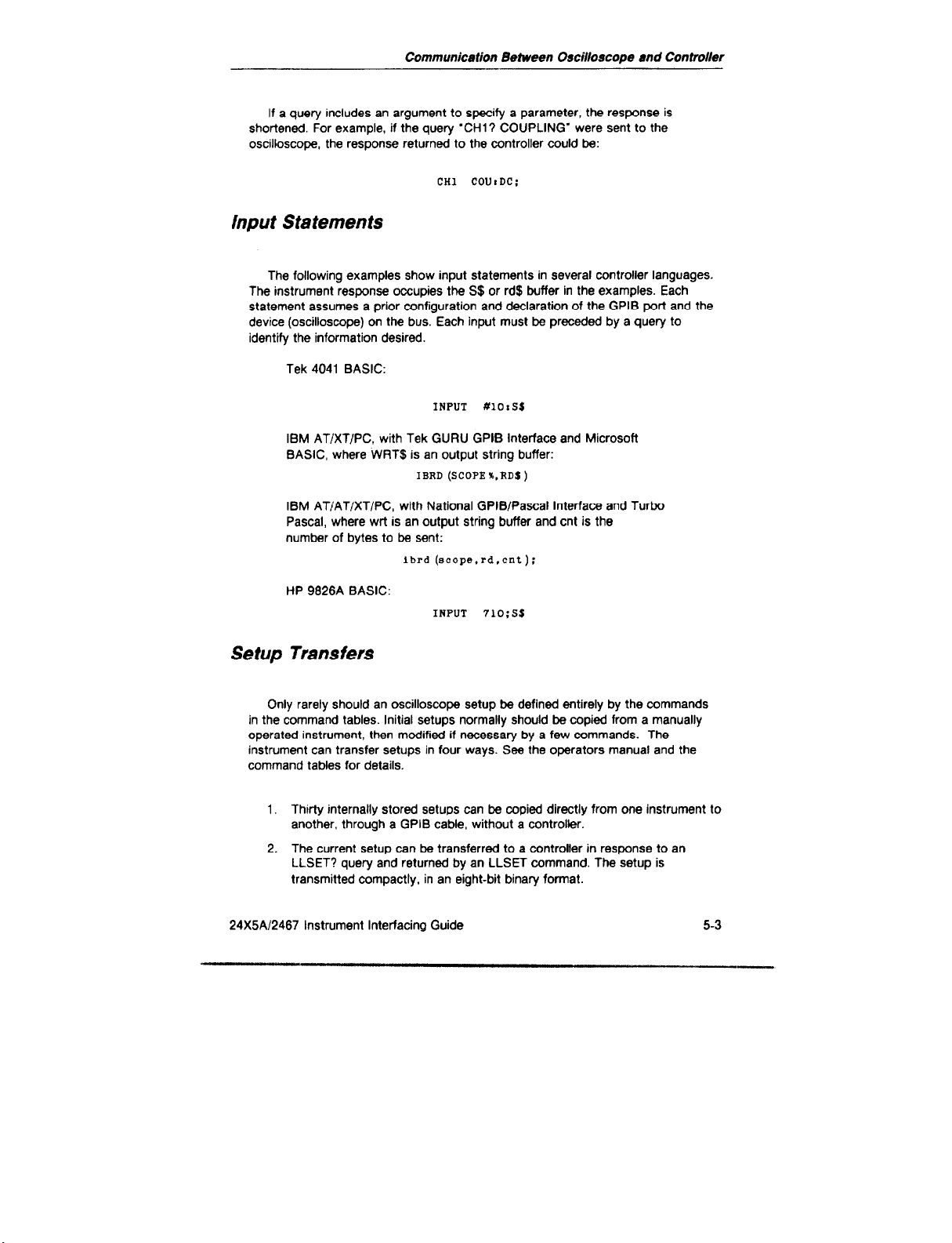
If a query includes an argument to specify a parameter, the response is
shortened. For example, if the query ‘CHl? COUPLING” were sent to the
oscilloscope, the response returned to the controller could be:
CHl COUrDC:
input Statements
The following examples show input statements in several controller languages.
The instrument response occupies the S$ or rd$ buffer in the examples. Each
statement assumes a prior configuration and declaration of the GPIB port and the
device (oscilloscope) on the bus. Each input must be preceded by a query to
identify the information desired.
Tek 4041 BASIC:
INPUT #lOrSS
IBM AT/XT/PC, with Tek GURU GPIB Interface and Microsoft
BASIC, where WRT$ is an output string buffer:
IBRD (SCOPE%.RDS)
IBM AT/AT/XT/PC, with National GPlBlPascal Interface and Turbo
Pascal, where wrt is an output string buffer and cnt is the
number of bytes to be sent:
lbrd(scope.rd,cnt):
HP 9826A BASIC:
INPUT 71033s
Setup Transfers
Only rarely should an oscilloscope setup be defined entirely by the commands
in the command tables. Initial setups normally should be copied from a manually
operated instrument, then modified if necessary by a few commands. The
instrument can transfer setups in tour ways. See the operators manual and the
command tables for details,
1. Thirty internally stored setups can be copied directly from one instrument to
another, through a GPIB cable, without a controller.
2. The current setup can be transferred to a controller in response to an
LLSET? query and returned by an LLSET command. The setup is
transmitted compactly, in an eight-bit binary format.
24X5A12467 Instrument Interfacing Guide
5-3

Communication Between Oscilloscope and Conlroller
3. The current setup can be transferred to a controller in response to a SET?
query and returned by a SET command. The setup is described fully in
ASCII characters, as defined in the command tables.
4. Thirty internally stored setups can be transferred to a GPIB controller, in
eight-bit binary format, using the LOADSEQ? query. The setups can be
sent to an oscilloscope with the LOADSEQ command.
Table 5-l
Command or Query Byte Counts
Command Maximum 6yte Count Maximum Byte Count
or Query with GPIB Only with All Options
LONGFORM Oif Ofl Off On
LLSET 90 92 154 156
SET
LOADSEQ
588 a45 a42
4043 4843 4043 4643
1303
Use LLSET? and LLSET to avoid wasting time and memory space, if your
controller can handle binary data.
Sending and Receiving ASCII Setups
To save a setup for future use, request a SET? string from the oscilloscope and
store it in a string variable. To set the instrument up with the stored parameters,
simply send the string back to the instrument.
400 Dim strS
410 Input #a prompt ‘%ETP”:s~~~! Input front
420 Dim atrs to len (strt)! M-dimension
. . .
450 Print m:atrs
5-4 24XW2467
to 1400
! Dimensloa variable
! panel setup into atrs
atr$ to actual
! string
Instrument Interfacing Guide

Communication Between Oscilloscope end Controller
Sending and Receiving Binary Setups
To obtain a Binary front-panel setup from the oscilloscope, send LLSET? and
store the response either in a string variable or in a numeric array according to the
capability of your controller. If the data is stored as an ASCII character string, the
controller must support E-bit ASCII characters or the data will be invalid. The
following 4041 example inputs the LLSET? response to a binary variable. To set
the instrument up with the stored parameters, simply send the array back to the
instrument.
. . .
400 Dim bind to 200 ! Dimension array variable
410 open #BI“GPIB (PRI=~,EOM=~O~)I”
420 Input #a prompt ‘fSET?“rbin$! Input front
! pane1 setup
450 Dim bin$ to len (binj)! Re-dimension bin$
! to actual array
. . .
460 Print #8rbin$
into bin$
SRQ and Event Codes
The most recent RQS ON or RQS OFF command (see Table 6-5, System
Commands) determines whether the instrument will generate the Service Request
(SRQ) message on the GPIB when either an error or a change in status occurs.
The enabling or disabling effect of the RQS command persists through power-off
and power-on, so the power-on SRQ also is controlled by the RQS command. The
SRQ indicator lights when the scope asserts the message on the bus.
If the controller is configured and programmed appropriately, the SRQ
interrupts the normal flow of the program. To service an interrupt, the controller
performs a Serial Poll. In response, the oscilloscope returns a Status Byte (STB),
which reveals the type of event that occurred. It also drops SRQ. If the instrument
has another event to report, it reasserts SRQ. The SRQ indicator extinguishes
when all events are reported. If the controller does not respond to the SRQ
message, the instrument continues to operate and communicate normally, even
though the condition that initiated the SRQ may invalidate a measurement.
The operator can generate SRQ and the user-request event (403). The SWRQS
ON; command enables or disables SRQ on closure of a switch connected to the
rear-panel STEP/AUTO EXT SWITCH connector, if RQS is on. The event is
included in the response to serial poll regardless of RQS. If a Tektronix probe with
an Identify button is connected to a vertical input, pressing the button with RQS on
also generates the SRQ and event 403.
24X5A/2467 Instrument Interfacing Guide
5-5

Communicetion Between Oscilloscope end Controller
To obtain more information about an event, the controller can send an EVENT?
query. The instrument responds with a number which indicates the specific event.
The various status bytes, events codes, and errors are defined in Appendix 6.
This program segment shows how to handle an SRQ, determine the instrument
status, and display the Status Byte and the associated event code on the
controller screen.
800????? ! Simple SRQ Handler
810 poll atb. dev ! poll bus. store status
820 input #dev prompt
830 print
stb; event ! print stb and event on SCI-*8ll
! byte in “stb”
“event?“:event
Interface Messages
This section describes the effects of GPli3 interface messages received by the
oscilloscope from a controller. See ANSI/IEEE Std 488-1978 for detailed
descriptions of interface messages and resultant interface states. These messages
are encoded as single bits or as single bytes. They may be explicitly generated by
the GPIB interface software in the controller or they can be composed in
hexadecimal format according to the IEEE Standard. They can NOT be sent as
character strings in the manner of instrument commands.
Local Lockout (LLO)
The Local Lockout message (LLO) may be received from the controller at any
time, whether the instrument is addressed or not. Once the LLO message has been
received, the My Listen Address (MIA) message locks out the front-panel
and the Go to Local (GTL) message enables them. The LLO message disables the
front-panel controls immediately if the instrument is addressed as a listener when
LLO is received. If the program sends the LLO message, it should also send the
GTL message to a listener-addressed device when the front panel should be active.
The LOCK indicator lights when front-panel operation is suspended.
If the controller sets the Remote Enable (REN) line false or if power is cycled off
and on, the effect of the LLO message is cancelled and the instrument controls
operate normally.
5-6 24X5Al2467 Instrument Interfacing Guide
controls

Communicetion Between Oscilloscope end Controller
Remote Enable (REN)
When the Remote Enable (REN) line is true and the instrument receives its
listen address (MLA), the oscilloscope can receive data from the bus and the
oscilloscope’s REM (remote) indicator lights.
If the REN line goes false, the instrument must receive MLA again before it can
receive commands. If a command is in process when REN goes false, it continues
to execute.
Go To Local (GTL)
If GTL is received, the instrument must receive MLA again before it can receive
commands. If a command is in process when GTL is received, it continues to
execute.
My Listen Address and My Talk Addresses (MLA and
MTA)
These messages condition the instrument to receive commands or respond to
queries and serial polls, respectively. They are received when the Attention (ATN)
line is true and the data on the GPIB is hexadecimal 20 or 40 plus the address
defined by GP EXER 11.
Unlisten (UNL) and Untalk (UN T)
These messages, equivalent to talk and listen address decimal 31, cancel the
MLA and MTA messages, respectively.
Interface Clear (IFC)
Receiving this message is equivalent to receiving both the UNL and the UNT
messages.
24X5A/2467 Instrument Interfacing Guide 5-7

Communication Between Oscilloscope and
Controller
Device Clear @CL)
The DCL message initializes communication between the instrument and the
controller. In response to DCL, the instrument clears any input and output
messages as well as any unexecuted control settings. Any errors and events
waiting to be reported are cleared except the power-on event. The SRO message
is cleared unless it is asserted for power-on.
Selected Device Clear (SDC)
This message performs the same function as DCL, only if the instrument has
been listen addressed.
Serial Poll Enable and Disable (SPE and SPD)
The Serial Poll Enable (SPE) message causes the instrument to transmit its
serial-poll status byte when it is talk-addressed. The Serial Poll Disable (SPD)
message returns the instrument to normal operation.
Command Handler
A command handler establishes communication between the controller and
oscilloscope, sends commands and queries to the oscilloscope, receives responses
from the oscilloscope, and processes the responses as required. The following
outline indicates a general sequence of command-handling functions.
1. Initialize the controller.
2. Disable the service-request handler until the program is ready to handle
them.
3. Get the GPIB address of the oscilloscope.
4. Enable the service-request handler.
5. Send a command to the oscilloscope.
6. Check for a response from the oscilloscope.
7. Process any response as desired.
6 Repeat steps 5 through 7 as desired.
5-8
24X5A/2467 Instrument Interfacing Guide

Communication Between Oscilloscope and Controller
Service-Request Handler
A service-request handler processes the interrupts generated by the SRQ
message on the GPIB. For example, when cursors have bean placed on points of
interest on a waveform, an operator can press a switch connected to the rear
panel which can cause the oscilloscope to assert SRQ. In response the controller
program can verify that the switch closure caused the interrupt, then query the
cursor measurement and compare the measured value to preset limits.
Events at which the oscilloscope asserts SRQ are identified in Appendix 8.
Some controllers can ignore service requests and others require a programmed
response to SRQ. Most controllers ignore service requests until SRQ interrupts are
explicitly enabled.
An SRQ handler needs an interrupt-enabling statement (eg. ON SRQ
statement-label) near the beginning of the program and a serial-poll subroutine with
that label. The ON SRQ statement directs program control to the serial-poll
subroutine whenever an SRQ interrupt occurs. The instrument maintains the
identity of an event that generates an SRQ until a serial poll is executed by the
interrupt-service subroutine.
The following general steps handle service requests from the oscilloscope:
1. Perform a serial poll to determine which device on the bus is requesting
service. The serial poll clears an SRQ generated by the oscilloscope, unless
more than one event has been identified.
2. Send an EVENT? query to the oscilloscope requesting service.
3. If the EVENT? query response is not zero, perform the appropriate
response to the event.
4. Return to the main program.
24X5A12467 Instrument Interfacing Guide 5-9

Communlcetion Between Oscilloscope end Controller
GPB Commands
The GPIB commands set instrument operating states, query the operating
states, and query the results of measurements. These commands are specified in
mnemonics that are related to function names or front-panel control names.
Commands follow the conventions established in the Tektronix Codes and Formats
Standard.
Command messages consist of headers, arguments, separators, and message
terminators.
A command contains at least a header. A few commands are fully specified by
a header. For example:
INIT
Arguments
Most commands require arguments after the headers. An argument must be
separated from its header by at least one space.
DELAY l.OE03
HMODE XY
Some arguments consist of primary and secondary arguments. Primary and
secondary arguments must be separated by a colon.
CHl VOLTS:6
ATRIGGER MODE:AUTOLEVEL
Some headers allow multiple arguments, which must be separated by commas.
A colon still separates primary and secondary arguments.
CHl VOLTS:5,COUPLING:DC,POSlTlON:1.2
VMODE CHl:OFF,CH2:ON,ADD:ON
5-10
_ ..” .“I_ _..._
24X5A/2467 Instrument Interfacing Guide

Communication Between Oscilloscope and Controller
Command Separator
Multiple commands can be combined in one message by separating the
individual commands with semicolons.
CHl VOLTS:5,COUPLING:DC;VMODE ADD:ON
Queries
In a query, the question mark must immediately follow the header, with no
space.
DVOLTS?
ATRIGGER? COUPLING
Message Terminator
Messages can be terminated with either EOt or LF, depending on the system
controller. The GPIB interface can be set to accept either terminator, using EXER
12, as previously explained. With EOI selected, a data byte received with EOI
asserted is recognized as the end of an input message. The instrument also
asserts EOI concurrently with the last byte of an output message. With the LF
setting, either an LF character or any data byte received with EOI asserted is
recognized as the end of an input message. With the LF selection, the instrument
transmits a Carriage Return character followed by Line Feed (LF) with EOI asserted
to terminate an output message.
Abbreviations
The defined words in headers and arguments can be entered at full length or
shortened to reduce typing and bus traffic. The command tables show the essential
characters of headers and arguments in upper-case characters and optional
characters in lowercase. The instrument accepts either upper case or lower case
characters. For example, any of the following commands are acceptable.
VMO?
vmadt
vmode invert
VMODE INVE
24X5A/2467 Instrument Interfacing Guide 5-11

Commuflk8tion Between Osciltoscope and Controlier
Numeric Arguments
The following table depicts the formats for numeric arguments in the GPIB
command set. Both signed and unsigned numbers
numbers are interpreted
as
positive.
are
accepted but unsigned
The symbol tnrx> indicates that
only one specific format is permitted, it is represented by nrl , nr2, or nr3.
any
of the three formats is allowed. When
fable 5-2
Numeric Argument Format for GPIB Commandr
Numeric
Argument
tnrx>
bol Number Format
SYl
<ml>
tnr2> Explicit decimal point
<nr3> Floating point in
Integers
scientific notation
+1,z
-3.2, +5.1, 1.2
+l.E-2, l.OE+2, l.E-2, O.O2E+3
Examples
-1, -10
5-12 24X5Al2467 Instrument Interfacing Guide

GPIB Commands
NOTE
Some commands are valid on/y with 2445A, 2455A, or 2467. These are indica ted by “(A) ” in the descriptions. The other commands are valid with the earlier
2445 and 2465
Table 6-1
Vertical Commands
CHl
CHl?
Header
Argument
Coupling:
POSition:
VARiable:
VOLls:
Coupling
POSition
VARiable
VOLts
Argument
AC
DC
FlFty
GND
tnrx>
tnrx>
tnrx>
Description
Selects Channel 1 vertical parameters.
Sets input coupling.
Sets position to tnrx> divisions from
center. Range extends -+ 11 divisions.
Sets VoltslDiv Var to the approximate
value of <nrx> in the range from 0 to
10. At tnrx> = 0, Vofts/Div is
calibrated.
Sets Volts/Div deflection factor to the
value of <nrx>. If tnrx> is not a
valid. calibrated VoltsiDiv for the
installed probe, the next higher
calibrated Volts/Div or the highest
VoltslDiv is used and an error event is
generated.
Query returns CHl VOL: tnr3>,
VAR:<nrl>. POS:tnr3>.
COU: <argument>;.
Response: CR1 COU:targument>;.
Response: CHl POS:tnR or nr3>;.
Response: CHl VAR: tnrl or nr2>;.
Response: CHl VOL:tnr2 or nr3>;.
PRObe
24X5A12467 instrument Interfacing Guide
CHl? PROBE must be queried
explicitly; it is not included in the CHl?
query response. The response string
indicates the probe attenuation coding:
Xl, X10, Xl00 or X1000.
6-1

GPIB Commands
Table 6-1 (cant)
Header
CH2
CH2?
CH3
CH3?
CH4
CH4?
VMOde
Argument
INVert:
INVert
BWLimit:
cl-lop:
CHI :
CH2:
Argument
ON
OFF
ON
OFF
ON
OFF
ON
OFF
ON
OFF
Description
Same as CHl plus INVert: argument.
Turns Channel 2 inversion on or off.
This command has the same effect as
VMOde INVert: <argument>.
Same as Cl-H, except query also
returns INV:<argument>. where
argument is either ON or OFF.
Same as CHl , except Coupling and
VARiable arguments are invalid and
POSition range is + 4 divisions.
Same as CH3.
Selects channels to be displayed, Chop
or Alternate channel-multiplexing mode,
limited or full vertical bandwidth, and
Channel 2 inversion. When all channels
are
off, Channel 1 is
Sets state of bandwidth limit.
Selects Chop or Alternate multiplexing.
Default is Chop (ON).
Turns Channel 1 on or off.
Turns Channel 2 on or off.
displayed.
CH3:
CH4:
ADD:
INVet-t:
6-2 REV OCT 1986 24X5A/2467 Instrument Interfacing Guide
ON
OFF
ON
OFF
ON
OFF
ON Selects normal or inverted Channel 2
OFF
Turns Channel 3 on or off.
Turns Channel 4 on or off.
Turns display of sum of Channel 1 plus
Channel 2 on or off.
display. Default is INV (ON).

Table 6-l (cant)
Header Argument Argument Description
GPl8 Commands
CHOp
CHl
CH2
CH3
CH4
ADD
INVert
BWLimit
Query returns current state of the
vertical display: VMO
CHl:targument>, CH2: <argument>.
CH3: <argument>, CH4: <argument>,
ADD:targument>,
BWL: <argument>, INV: <argument>,
CHO: <argument>.
24X5A/2467 Instrument Interfacing Guide
REV OCT 1986 6-3

GPIB Commands
Table 6-2
Horizontal Commands
Header
HORizontal
Argument
ASEcdiv:
BSEcdiv:
MAGnify:
POSition: <nrx>
Argument
tnrx>
tnrx>
ON
OFF
Description
Selects Horizontal display
parameters.
Selects A-Sweep speed in
seconds per division. Range for
the 2465A and 2467 is from 5E-9
to 1.5. Range for the 2445A and
2455A is from 1 OE-9 to 1.5. If the
selected speed is faster than the
current B Sweep, B-SeclDiv is set
equal to A-Sec/Div. The effects of
MAGnify: are independent of
ASEcdiv:.
Selects B-Sweep speed in
seconds per division. Range for
the 2465A and 2467 is from 5E-9
to 0.15. Range for the 2445A and
2455A is from lOE-9 to 0.15. B-
Sec/Div is updated whether B
Sweep is active or not. If the
selected B-Sec/Div is slower than
the current A-SeciDiv, A-SeclDiv is
set equal to B-SeciDiv. The effects
of MAGnify: are independent of
BSEcdiv:.
Turns Xl 0 sweep magnification on
or off.
Sets the starting position of the
sweep in divisions from the left
edge of the screen over the range
+ 5.46 divisions.
6-4
TRACEsep:
REV SEP 1987 24X5A/2467 Instrument Interfacing Guide
tnrxz
Offsets B Sweep from A Sweep or
b-B Sweep from the B Sweep
with the reference delay by the
indicated amount, in the
approximate range from 0 to -4
divisions.

Table 6-2 (cant)
GPIB Commnnds
Header
HORizontal?
HMOde
HMOde?
Argument
ASEcdiv
BSEcdiv
MAGnify
POSition
TRACEsep
ALTernate
ASWeep
BSWaep
XY
Argument
Description
Query returns the horizontal
selections: HOR ASE: tnrx>,
BSE:<nrS>, MAG:targument>.
POS:tnrS>, TRACE:tnr2>;.
String
is either ON or OFF.
Selects Horizontal display mode.
Choices are mutually exclusive.
Selects both A Sweep and B
Sweep for display. This is
equivalent to pulling the SEC/DIV
knob out.
Selects only the A Sweep for
display.
Selects only B Sweep for display.
If A-SeclDiv and B-SeclDiv are
equal, then a settings conflict error
is generated.
Selects XY mode, where Channel
1 drives the horizontal display.
Query returns HMO string;, where
the string represents one of the
possible Horizontal display modes.
24X5AI2467 Instrument Interfacing Guide
6-5

GPll3 Commends
Table 6-3
Trigger Commands
Header
ATRigger
MODe:
Source:
:
Coupling:
Argument
-EVeI:
Argument Description
Selects A-Trigger parameters.
AUTOBaseline
AUTOLevel
NORmal
SGLseq
Cl-f1
CH2
CH3
CH4
LlNe
VERtical
AC
DC
HFRej
LFRej
NOlserej
FLDl
CLD2
ALTernate
LINES
<nrx>
Selects Mode from the list of
arguments. (AUTOBaseline is
equivalent to AUTO.)
Selects Source from the argument
list.
Selects Coupling from the
argument list. (Use DC for most
applications.)
Only with the available TV option,
selects TV trigger mode.
Sets Trigger Level in volts with
rertical channel sources or in
dimensionless units with LINE
source. The numeric argument is
stored as a target value. Trigger
eve1 is set at the target value or at
I limit value defined by the trigger
;ource. The limits are + 18 times
he VoltslDiv setting for CH 1 and
:H 2, f 9 times the Volts/Div
jetting for CH 3 and CH 4. and
k 10 for LINE. A level query
eturns the value of the current
arqet
6-6 REV SEP 1967 24X5Al2467 Instrument Interfacing Guide

Table 6-3 (cant)
Header
ATRigger?
Argument
INIt
SLOpe:
BENdsa:
HOLdoff:
BENdsa
Coupling
HOLdoff
LEVel
MODe
SLOpe
SOUrce
Argumenr
MINUS
PLUS
ON
OFF
<nrx >
Description
Measures signal peaks at the ATrigger source and sets trigger
level at the midpoint between
peaks. (A)
Selects Slope 01 the A-Trigger
signal.
Sets the B ENDS A mode ON or
OFF.
Sets
Holdoff to the value of
tnrx> in the arbitrary range from
0 to 10, with 0 representing
minimum (normal) holdoff.
Query returns ATR BEN:string,
COU:string, HOL:string,
LEV:tnrP>, MOD:string,
SLO:string. SOU:string.
Arguments MAX, MINI, READY,
and TRIGD must be requested
explicitly, e.g. ATR? MINI,MAX.
MAXimum
24XSA/2467 Instrument Interfacing Guide
Query-only returns ATR
MAX:cnrx>;. The value of
<nrx> represents the most
positive peak voltage, measured in
volts, at the A-Trigger source at
the most recent operation of the
INlT@50% button with the A
Trigger or in response to the most
recent ATRigger INIt command
or the most recent Auto Level
acquisition or the most recant
ATRigger MODe AUTOLevel
command. Normally, the ATRigger
INlt50 command should be sent
just prior to
MAXimum auerv.
REV OCT 1966
an
ATRigger?
6-7

GPIB Commands
Header Argument
MINImum
READY
TRIGD
BTRigger
MODe:
Table 6-3
Argument
RUN
TRIGGERAble
DRTRigger
(cant)
Description
Query-only returns ATR
MINI:tnrx>;. The value of
<nrx> represents the most
negative peak voltage, measured
in volts, under the same conditions
as ATRigger? MAXimum.
Query-only returns ATR
READY:string;. String is ON if the
single-sequence READY indicator
is ON. Otherwise, string is OFF.
Query-only returns ATR
TRIGD:string;. String is ON if
TRIG’D indicator is illuminated.
Otherwise, string is OFF.
Selects B-Trigger parameters.
Selects B-Trigger Mode.
Only with the available CTT,
conditions the instrument to direct
front-panel Slope and Level
controls to the B-Trigger
associated with the A REF delay.
This command forces Delta
ModeTime on unless Delta
ModePertime or Delta
ModeCperfime is on. If Delta
MO& Cpertime is on, the
command forces a change to Delta
ModePertime. (A)
DTRlgger
6-6 24X5A12467 Instrument Interfacing Guide
Only with the available ClT,
conditions the instrument to direct
front-panel Slope and Level
controls to the B-Trigger
associated with the A delay. This
command forces Delta Mode:Time
on unless Delta Mode:Pertime or
Delta Mode:Cpertime is on. If
Delta Mode Cpertirne is on, the
command forces a change to Delta
Mode:Pertime. (A)
”

Table 6-3 (cant)
G/W Commands
Header Argument
SOUroe:
Coupling:
LEVel:
Argument
ALTSlope
CHl
CH2
CH3
CH4
VERtical
AC
DC
HFReJ
LFRej
NOlserej
<nrx>
Description
Only with the available C‘TT,
included only for compatibility with
earlier instruments, and not
recommended for new
applications; conditions the
instrument to direct front-panel
Slope and Level controls to the BTrigger associated with both A
delays, maintaining common levels
and opposite slopes. This
command forces Delta Mode:Time
on unless Delta Mode: Pertime or
Delta Mode:Cpertime is on. If
Delta Mode Cpertime is on, the
command forces a change to Delta
Mode:Pertime. (A)
Selects B-Trigger Source.
Selects B-Trigger Coupling. (Use
DC for most applications.)
Sets Trigger Level in volts. The
numeric argument is stored as a
target value. Trigger level is set at
the target value or at a limit value
defined by the trigger source. The
limits are _+ 18 times the Volts/Div
setting for CH 1 and CH 2 and +9
times the VoltslDiv setting for
CH 3 and CH 4. A level query
returns the value of the current
target.
24X5A12467 Instrument Interfacing Guide
Measures signal peaks at the B-
Trigger source and sets trigger
level at the midpoint between
peaks. (A)
8-9

GPIB Commends
Table 6-3 (cant)
Header
BTRigger?
SLOpe:
DLEVel:
DSLope:
Coupling
LEVel
MODe
SLOpe
SOUrce
DLEVel
I
DSLOpe
-
Argument
Argument
MINUS
PLUS
tnrx>
MINUS
PLUS
Description
Selects Slope of the B-Trigger
signal.
Only with the available ClT, sets
trigger level for the B Sweep
controlled by the A delay setting,
in the same manner as LEVel sets
trigger level for all other B-Trigger
functions. (A)
Only with the available ClT,
selects trigger slope for the B
Sweep controlled by the A delay
setting, in the same manner as
SLOpe sets slope for all other BTrigger functions. (A)
Query returns ETR MOD:string,
COU:string, SLO:string,
SOU:string, LEV:<nrx>;.
BTRigger? query response only
with the available CTT: BTR
MOD: string, DSL:string,
DLEV: <nrx>, COU: string,
SLO:string, SOU:string,
LEV:<nrx>;. (A)
610 24X5Al2467 Instrument Interfacing Guide

Table 6-4
Delay and Delia Commands
GPIB Commands
Header Argument
DELAY <nrx>
DELAY?
DELTa
MODe:
Argument
OFF
CPERTime
CTlMe
Description
Sets sweep delay to tnrx>
divisions in the range from -0.05
to 9.95. This command has the
same effect as DTIME REF:
tnrx>. The value of -0.05
assures that the A-Trigger event is
visible on the B Sweep.
Query returns the current delay
setting in divisions: DELA
tnr2>;. This response is not
included in a SET? query but the
DTIME REF: tnrx> response to
the query contains the equivalent
information.
Sets Delta-display parameters.
Selects or cancels a Delta mode.
Activates l/At cursors with ASweep or B-Sweep display. With
ALT horizontal display, the
command produces an error
response. (A)
Activates A.t cursors with A-Sweep
or B-Sweep display. With ALT
horizontal display, the command
produces an error response. (A)
PERtime
TlMe
24X5Al2467 lntrument Interfacing Guide 6-11
Activates l/At cursors with ASweep display; activates 1 /delta-
delay-time with Alternate or B-
Sweep horizontal display.
Activates At cursors with A-Sweep
display; activates delta-delay-time
with Alternate or B-Sweep
horizontal display.

GPI6 Commands
Table 6-4 (conl)
H88d8r
DELTa?
DTlme
DTlme?
Argument
TRACKing:
MODe
TRACKing
REFerence
DELTa:
REFerence
DELTa
Argument
vous
ON
OFF
tnrx>
tnrxb
D8aCriptiOn
Activates AV cursors.
Selects Tracking or Independent A
REF control mode. Default is
Tracking (ON).
Cluery returns DELT
MOD:string.TAACK:string;.
Sets reference delay, At cursor, or
l/At cursor tnrx> divisions from
A-Sweep start or left edge of the
display, in the range from - 0.05
to 9.95. If Tracking is on, the delta
delay or cursor moves as required
to maintain its distance from the
reference, within the -9.05 to
9.95 range.
Sets delta delay, At cursor, or l/At
cursor <nrx> divisions from the
reference delay or cursdr. The sum
of the reference setting plus the
delta setting must be within -0.05
to 9.95 divisions.
Query returns the Delta Time
settings in divisions: OTI
REF:tnr2>, OELT:tnr2>;.
TOELta?
6-12 24X5A/2467 lntrument Interfacing Guide
Query returns the delta time
setting in seconds, hertz, percent,
or degrees: < nr3> ;. No
‘TOELTA’ header is returned so
high-level input drivers can
process
the response. NOTE: if
the query follows a MESSAGE
command, a DELTA
MODE: <argument> ; command
nust be given again to restore the
delta reading. (A)

Table 6-4 (cant)
GPIB Commsnds
Header
DVOlts
DVOlts?
VDELta?
Argument
REFerence:
DELTa:
REFerence
DELTa
Argument
<nrx>
<nrx>
Description
Sets the reference cursor tnrx>
divisions from the center of the
display, within the +4.O range. If
Tracking is on, the delta delay or
cursor moves as required to
maintain its distance from the
reference, within the + 4.0 range.
Sets the delta cursor tnrx>
divisions from the reference
cursor. The sum of the reference
setting plus the delta setting must
be within
Query returns the delta volts
settings in divisions: DVO
REF:tnrP>,DELT:tnr2>;.
Query returns the delta volts
setting in volts, or percent:
tnrx>;. No ‘VDELTA” header is
returned so high-level input drivers
can process the response. NOTE:
If the query follows a MESSAGE
command. a DELTA
MODE:VOLTS; command must be
given again to restore the delta
reading. (A)
Table 6-5
System Commands
Header
BA Lance
ERRor?
24X5A/2467 Instrument Interfacing Guide
Argument Argument Description
Initiates the vertical DC Balance
procedure. The instrument
initializes after BALANCE (see
INIt).
Query returns ERR <nrl>;.
Response is equivalent to EVEnt?
query. Command is included for
compatibility with earlier
instruments.
6-13

GPIB Commands
Table 6-5 (cant)
Header
EVEnt?
ID?
Argument Argument
Description
Query returns EVE <nrl>;. The
value of tnrl> is the most
severe of the current errors. Errors
are prioritized into three levels, but
only the most
maintained for each level. If no
error is pending, 0 is returned.
Event codes are listed in Tables
B-l and B-2.
Query returns ID
TEK/model,VBl .l .SYS:FVx.
BB:FVy, [string:FVtnrl >,]
GPIB:,FVz;. The word model
stands in place of the strings
2445A, 2455A, 2465A,
The characters x, y, and z stand in
place of the firmware version
numbers of the oscilloscope.
Buffer board, and GPIB option,
respectively. The section in
brackets is repeated for each
installed option, including TV and
CTT. String V61 .l indicates that
the GPIB interface is compatibfe
with the VEtl .l version of the
Tektronix Codes and Formats
standard.
recent error
or 2467.
iS
INlt
6-14 24X5A:2467 InstrumeM Interfacing Guide
Sets the instrument and all options
except the GPIB to an initialized
state equivalent to cycling power
off and on. The GPIB system-
command states (OPC. RQS,
WARning, and LONgform) are not
nitialized. (RQS is not changed by
oower-downlpower-up.) This
:ommand should be the final or
3nly command in a message.
Mditional commands in the same
message give unpredictable
results.

Table 6-5 (cant)
dPlf3
Commends
Header Argument Argument
LLMessage %<byte>tbyte>...
LLMessage?
LLSet % <byte> <byte>...,
Description
Sends binary
of the CRT readout. The
displays the block of binary data
according to the codes in Tables
14 and 15. The first pair of bytes
represent the number of
characters. The last byte is the
two’s complement of the least
significant byte of the sum of the
character codes.
Query returns the contents of the
top line of the CRT readout in a
binary block of data, in the form:
LLM %<byte> <byte> . .
<byte>;. The first two bytes
followlng the % character are a
16-bit count of the bytes
follow.
according to Tables
not ASCII. The last byte of the
block is the two’s complement of
the least significant byte of the
sum of data bytes. (See
MESsage? for ASCII coding of the
readout.)
Returns a previously acquired
setup
Level binary Setup data
generated only by a LLSet? query.
data to the
top line
readout
that
The display is encoded
to the instrument. The Low
14 and 15,
can be
24X5A/2467 Instrument Interfacing Guide 6-l 5

GPIt9 Commands
Table 6-5 (cant)
Header
LLSet?
MESsage
Argument
‘string”
Argument
Description
I-
Query response is a block of
binary data representing the
instrument setup in the form:
LLSET %<byte><byte>.
%tbyte> <byte>;. The block of
data comprises a sub-block for
each installed option. Each sub-
block begins with a % character
followed by two bytes which are a
16-bil count of the bytes that
follow. The last two bytes of each
sub-block are the two’s
complement of the least significant
byte of the sum of data bytes,
followed by a comma, except that
the final block is followed by a
semicolon.
NOTE
The L LSET? query behaves
unpredictably if the controller
recognizes the LF character as the
end of a message.
Displays up lo 32 mostly-ASCIIcoded characters lo the top row of
the readout. The string must be
enclosed in quotes and may
exceed 32 characters because of
character translations. The display
is filled with blanks after the
specified characters. If the string
specifies more than 32 display
characters, the command is
ignored except for an error
*esponse. Table C-l lists the
:haracter set and codes.
6-16
24X5A12467 Instrument Interfacing Guide

Table 6-5 (cont)
OPll3 Commands
Header
MESsage?
OPC
Argument
ON
OFF
Argument
Description
NOTE
Before a TDEL TA ? or VDEL TA ?
query following a MESSAGE
command, a DELTA
MODE:targument>; command
must
be given
to
restore
the d&a
reading.
Query returns an ASCII
representation of the top line of
the display: MES ‘string”;. The
string may exceed 32 characters
due to character translations.
Enables the instrument to assert
SRQ as an * Operation Complets
indication after certain diagnostic
and option commands. OPC
initializes to OFF at power-up.
Only with the available CTT, OPC
enables Event 778 at CTT
measurement completion and, if
RQS is ON, OPC enables SRQ at
CTT measurement completion.
Reading the event code by an
EVENT? query clears the event
and the SRQ. The event and SRQ
remain clear until the CTT
measurement has been read by
the appropriate query and a new
measurement is complete.
OPC?
24X5Al2467 Instrument Interfacing Guide 6-l 7
Query returns either OPC ON; or
OPC OFF;.
-.---.

t?PlB Commends
Table 6-5 (cant)
Header
READOut
READOut?
RQS
RQS?
Argument
ON
OFF
ON
OFF
Argument
Description
Turns the CRT SCALE FACTORS
readout ON or OFF.
Query returns READ0 string;.
String is either ON or OFF,
indicating the state of the Scale
Factors readout.
Enables the instrument to assert
SRQ on detection of specific
events, including error conditions.
The power-on SRQ depends on
the most recent RQS ON/OFF
before power-off. (Note that this
command is distinct from the RQS
message on the GPIB. which is
one bit in the serial poll response.)
Query return either RQS ON; or
RQS OFF;.
6-16
.,----- .”
24X%/2467 Instrument Interfacing Guide

Table 6-5 (cant)
GPIB System Commands
Header
SETtings?
LONgform
LONgform?
WARning
Argument
ON
OFF
ON
OFF
Argument Description
Query returns an ASCII string of
commands
tables that represent the current
instrument setup. The string
contains all required headers and if
it is returned to the instrument, it
should not be preceded by
SETtings or any other header.
LLSet? and LLSet should be used
to acquire and restore complete
instrument settings to save time
and memory space.
The SETtings? query may give
inconsistent results with SEC/D/V
VARiable. If the variable is
manually set for an A Sweep
slower than the next slower speed
settable by the SEC/DIV switch,
the SETtings? query will attach the
variable to the B Sweep, and fhe
A Sweep will be shown at the next
slower speed selectable by the
switch.
Enables queries to respond with
the full length versions of
commands. When LONgform is
OFF, the shortest acceptable
version of commands are used in
query responses. Default
argument is OFF.
Query returns either LONGFORM
ON; or LONG OFF;.
as
defined in these
NOTE
WARning?
24X5Al2467 Instrument Interfacing Guide
Enables SRO assertion on
detection
Warning initializes to ON at
power-up.
Query returns either WARN ON;
or WARN OFF;.
of a
potential error.
6-19

System Commands
Table 6-5 (cant)
Header
SAVe <nrx>[:STEP][:‘string”]
SAVe tnrxr[:BEGIN][:‘string”]
SAVe tnrx>[:END][:‘string”]
RECall <nrx> [:SEQ]
Argument
Argument
Description
Saves the current setup as setup
tnrx>, in the range from 1
through 30. The optional STEP,
BEGIN, and END arguments
define attributes for sequential
recall operation. BEGIN and END
define sequence looping
boundaries. The STEP argument is
assumed if neither BEGIN nor
END are given. The optional
“string” with up to 7 characters
must be delimited by quotes. The
string defines a name for the
setup. If no name is given in the
command, the previous name of
the setup tnrx> is retained,
except that the name ‘NOTSET”
will change to ‘SET.” (A)
NOTE
The string can include any of the
characters, A..Z, 0. .9, and the
following punctuation marks.
. : , ? t - I < > %
Lower case letters are converted
to upper case. The space
character is converted to a pericd,
unless it is not the first character
in a name and no other non-space
characters follow it. The following
punctuation characters are
translated to lower case English
characters or to Greek characters.
& to k, to m, ( to n. ! to p, = to s,
] to t, # to lower case mu (micro),
[ to upper case omega (ohms)
Sets the instrument to saved
setup <nrx>, in the 1 to 30
‘ange. and initiates the Sequence
mode if the argument string
‘:SEQ” is included or cancels the
Sequence mode if the argument is
not included. In Sequence mode,
the front-panel STEP/AUTO
Jutton selects following setups. (A)
6-20 24X5A/2467 Instrument Interfacing Guide

Table 6-5 (cant)
System Commands
Header Argument
RECall NEXT
LOAdseq
LOAdseq?
AUTOSetup
SWRQS
% <binary data>, . . .
Argument
Description
In Sequence mode only, selects
the next higher numbered setup
saved in the instrument, or the
previous setup with the BEGIN
attribute if the current setup has
the END attribute. RECall NEXT is
invalid after RECall tnrx>
without the ‘:SEQ” colon and
argument. (A)
Loads 30 setups into instrument
memory which can then be
recalled as desired. The binary
data is defined only by the
LOAdseq? query. (A)
Query returns 4719 to 4723 bytes
of binary setup data which is valid
to send with a LOAdseq
command. (A)
NOTE
The LOADSEO? query behaves
unpredictably if the controller
recognizes the LF character as the
end of a message.
Initiates an automatic setup of
scale factors, trigger, and intensity.
IAl
Enables or disables a user-request
Went (403) on closure of a switch
connected to the rear-panel
STEP/AUTO EXT SWITCH
connector. An SRQ will be
generated if RQS is on (see RQS
command). The event is included
n the response to serial poll
,egardless of RQS. (A)
24X5A12467 Instrument Interfacing Guide
6-21
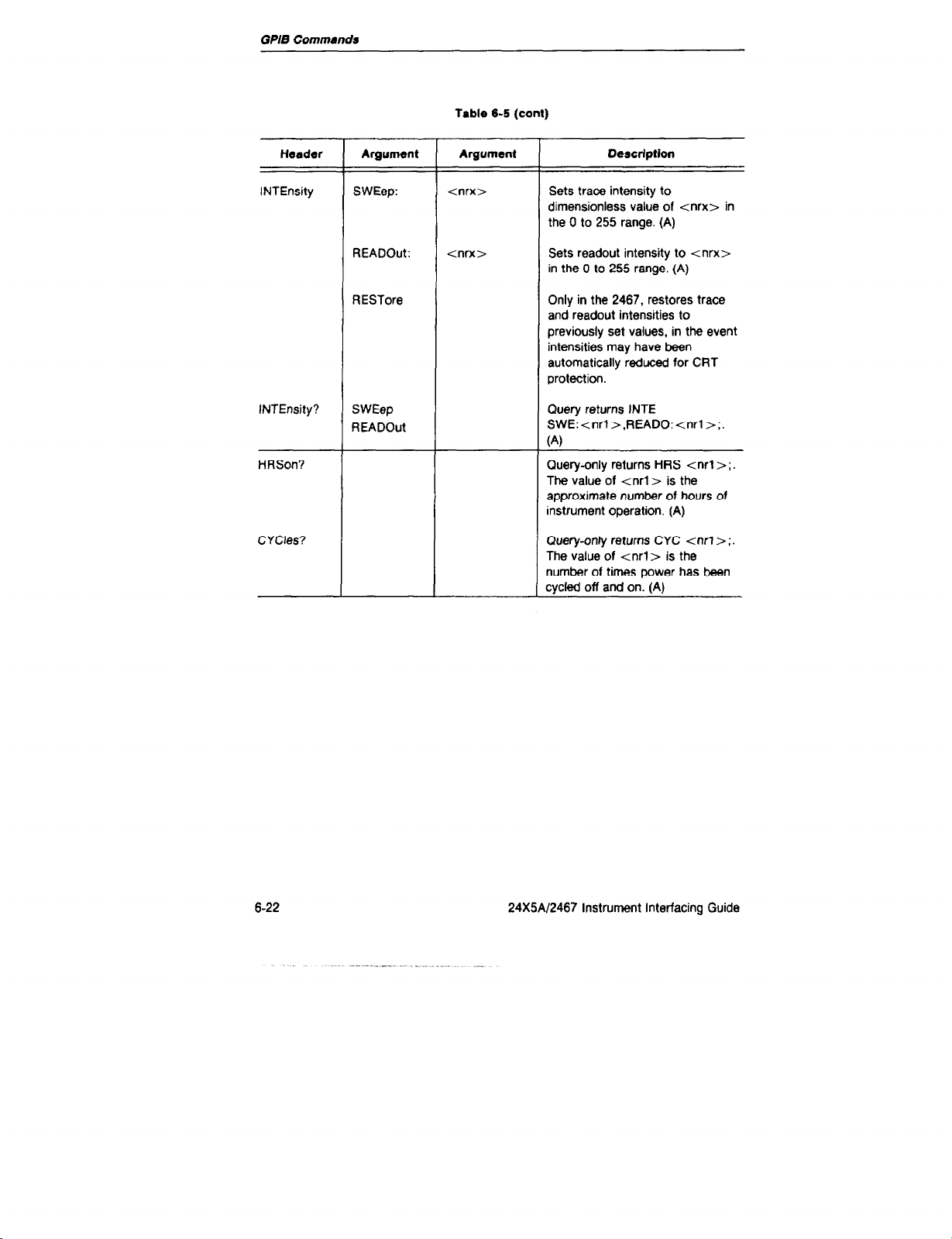
GPIB Commands
Table 6-5 (cant)
Header
INTEnsity
INTEnsity?
HRSon?
CYCles?
Argument
SWEep:
READOut:
RESTore
SWEep
READOut
Argument
<nrx>
tnrx>
Description
Sets trace intensity to
dimensionless value of tnrx> in
the 0 to 255 range. (A)
Sets readout intensity to tnrx>
in the 0 to 255 range. (A)
Only in the 2467, restores trace
and readout intensities to
previously set values, in the event
intensities may have been
automatically reduced for CRT
protection.
Query returns INTE
SWE:tnrl>,READO:<nrl>;.
(4
Guery-only returns HRS tnrl > ;.
The value of tnrl > is the
approximate number of hours of
Instrument operation. (A)
Query-onfy returns CYC tnrl r ;.
The value of <nrl> is the
number of times power has been
sycled off and on. (A)
6-22
24X5A/2467 Instrument Interfacing Guide

Table 6-6
GPIB Command get for the TV Option
GPIB Conmandr
Header
TVClamp ON
TVClamp?
TVLine tnrx>
TVLine?
LCNTStart PREfld
LCNTStart?
Argument
OFF
ATFld
Argument
Description
Selects AC and TV (back-porch)
Clamp input coupling for CH 2.
If the TV (back-porch) Clamp is
active, CH 2 input coupling
changes to AC and the N (backporch) clamp is turned off.
Otherwise, the CH 2 input coupling
does not change.
Query returns either NC ON or
TVC OFF.
Selects N line number <nrx> for
the A Trigger.
Query returns NL tnrl>;. The
value of tnoo is the selected
line number.
Selects line count beginning 3 lines
before field-sync pulse (Format 2).
Selects line count beginning at
field-sync pulse (Format 1).
Query returns tine 1 definition:
either LCNTS PRE; or LCNTS
ATF;.
LCNTReset FlOnly
BOTh
LCNTReset?
24MAl2467 Instrument Interfacing
Selects line count reset only on
tield 1 (Format 2).
Selects line count reset on both
field 1 and
Query returns Line count reset
status: either LCNTR FlO; or
LCNTR BOT;.
field 2
(Format 1).
Guide 623

GPlB Commnnds
NOTE
C77 measuremenk are requested with the CTSend? query command. DELAY?
and DTlme? 9ueries return delay and delta settings, not measurements.
Table 6-7
Counter/Timer/Trigger GPIB Commands
Header
CTRdy?
CTSend?
Argument
IMMediate
WAlt
Argument Description
Query returns CTR 1; if a CTT
measurement is available or CTR
0; if not. If no measurement
function is active, or if a
measurement function is
suspended because another option
is using the display, an optionnot-in-correct-mode error is
generated.
Command requests the result of
any of the following
measurements: frequency, period,
totalize. delay-time, deltadelaytime, or 1 /delta-delay-time. The
measurement is returned in format
tnr3>. The ‘?’ following CTSend
has no effect and is optional. If the
measurement is invalid, one of the
following error codes is returned in
place of the measurement:
1 .OE +99 for missing B trigger.
1 .OE + 98 for missing A trigger.
6-24
1 .OE +97 when the time interval in
l/At mode is less than 1% of full
scale.
1 .OE+96 for Totalize mode
Dverflow.
24X5Al2467 Instrument Interfacing Guide

Table 6-7 (cant)
GPlB Commands
Header
CTSend?
(cant)
COUNt
-I-
Argument Argument
CTT Setup Commands
EVEnt:
ATRigger
WREcognizer
Description
If no measurement function is
active, or if a measurement
function is suspended because
another option is using the display,
an option-not-in-correct-mode
error is generated.
A measurement is sent only once
then cleared. A new measurement
must be completed before another
value will be sent.
CTSend with no argument or the
WAlt argument conditions the
instrument to send no response
until the measurement is complete.
The IMMediate argument
conditions the instrument lo send
a null message (talked with
nothing to say) if the measurement
is not complete.
Configures the Count function.
MODe:
COU Nt?
Cl-f
24X5A/2467 Instrument Interfacing Guide REV OCT 1986 6-2.5
EVEnt
MODe
COUNt
DBEvents
LTRigger
OFF
FREquency
TOTal
PERlod
If the Word Reccgnizer Option is
not installed and If EVEnt:WRE is
received, an option-not-installed
error is generated.
Query returns COUN MOD:string,
EVE:string;. or COUN arg:string; if
an argument is given in the query.
Selects or cancels a CTT function.
Selecting any function cancels any
other selected function and sets
B-Trigger mode to Run AfI Dly.

GPIB Commands
Table 6-7 (cant)
Header
Cl-r?
DBEvents
DBEvents?
Argument
RESET
COUNt:
EVEnt:
STArt:
SWEep:
30UNt
EVEnt
STArt
SWEep
Argument
CTT RESET resets any count or
time measurement currently in
progress, including delay and delta
time.
Query returns ClT string;. The
‘string” names the current CTT
function.
<nrl>
BTRigger
WREwgnirer
ATRigger
WREcognizer
ASWeep Selecting SWEep:BSWeep sets
BSWeeo
Sets Delay-by-Events for tnrl >
events in the range 1 - 4194303,
indusive. If an out of range or
noninteger number is received a
numeric-argument error is
generated.
If the Word Recognizer Option is
not installed and if
EVEnt:WREcognizer or
STArkWREcognizer is received,
an option-not-installed SRQ error
is sent.
Selecting STArkWREcogniter
WREcognizer sets SWEep to
9sweep.
BSWeep STArt to ATRigger.
3uery returns DBE SWE:string,
STA:string, EVE:string,
30UN: <nrl>;, or DBE
wg:string; if an argument is given
n the query.
Description
626 24X5A/2467 Instrument Interfacing Guide

Table 6-7 (cant)
W/B Commands
Header
Argument
LTRigger ASWeep:
LTRigger?
RESolution
AUTO
RlNs
RlOOps
RIOPS
RESolution?
Argument
AANdb
AORb
WREcognizer
WREcognizer
Description
Configures the Logic Trigger
function. If the Word Recognizer
Option is not installed and if either
the ASW:WRE or BSW:WRE
command is received, then an
option-not-installed error is
generated.
Query returns LTR ASW:string; or
LTR BSW:WRE;.
Sets the resolution of delay and
delta-delay measurements.
Quetv returns RES strina:
24X5AI2467 Instrument Interfacing Guide 6-27

GPIS Commands
Table 6-8
Word Recognizer GPIB Commands
Header
WREcognizel
Argument
CLOck:
RADix:
WORd:
Argument
ASYnch
DNClock
UPClock
BlNary
HEX
OCTal
<ASCII binary
data>
Description
Configures the Word Recognizer.
The RADix: argument controls
only the format of the Word
Recognizer display and manual
settings.
The format of ASCII binary data is
#Y followed by 17 digits, where
each digit may be either 0, 1, or X
(don’t care). Spaces may bs used
anywhere to separate groups of
digits. The option will accept
ASCII binary data command
arguments without the #Y prefix.
The following are all valid and
equivalent:
WOR:#Yl 00X01X10
0x0x110x,
WOR:#Y100X01X100
x0x1 10x.
WOR: 100x0 1x10
oxox 110x.
WOA:#Yl 0 0x0 1x1
00x 0x1 10x
The digit order is qualifier bit, then
a 16-bit word in most-significant to
least-signifcant bit order. All 17
digits must be sent. If an error is
detected in the ASCII binary data
argument, a command-argument
error is generated.
6-28
REV OCT 1986 24X5Af2467 tnstrument interfacing Guide

Table 6-6 (cant)
GPIB Comnrands
Header Argument Argument
WREcognizer?
CLOck
RADix
WORd
GPIB Command Set for the DMM Option
1 OFbgument DMM Header
susp
Description
If the Word Recognizer Option is
not installed and any word
recognizer command or query is
received, an option-not-installed
error is generated.
Query returns WRE RAD:string,
CLO:string,WOR: <ASCII binary
data>;. For example, WRE?
WOR returns WOR:#Yl
00x01x10 0x0x110x;
Table 6-9
Description
Turns off the DMM. Any DMM function
command turns the DMM on. The DMM
SUSP; command suspends DMM operation
to permit another function to occupy the
readout space. The only difference between
DMM SUSP and DMM OFF is that the next
time a OMM function is selected, if it is the
same function previously suspended, the
reference value and the states of SMOOTH,
AUTO, etc. are maintained.
DMM?
DMMSend
DMMSend?
24X5A/2467 Instrument Interfacing Guide
Query returns DMM ON;, DMM SUSP;, or
DMM OFF;.
Command/query returns the displayed DMM
measurement in tnr3> format, adjusted to
basic units of volts, ohms, or amperes.
DMMSend and DMMSend? have identical
effects. No response will be given unless or
until a measured value is displayed. If the
value is out of measurement range, the value
1 .OE +99 is returned.
6-29

GPlB Option Commands
Table 6-9 (cant)
Header
DlSplay
DISplay?
MlNMaxres
RANge inrx>
RANge?
REFset
Argument
MINtmum
MAXimum
REF
NORmal
I
<nrx>
1
Description
Select the minimum or maximum
measurements made since the function was
selected or since MinlMax Reset.
Selects the present value of the reference.
Selects the most recent measurement.
To receive the present minimum value over
the GPIB, for example, send DIS MINI;
followed by DMMSEND;.
Query returns DIS MINI;, DIS MAX;, DIS
NOR; or DIS REF;.
Resets the minimum and maximum
accumulators to the next valid measurement
value.
Selects the range of the DMM function
suited to measuring the value <nrx>.
Query returns RANGE <nr3>;. The range
value will ba stated in basic units of volts,
amperes, or ohms.
Sets the reference to tnrx>. If the
argument is zero, the reference turns off.
Also, if the argument is a negative value and
the present function doesn’t allow negative
values, the reference turns off. The argument
is rounded up to the closest value
represented by the DMM (1 part in 40,000).
If the argument is too large for the function,
an error is generated and the reference
remains unchanged. If no argument follows
REFSET, the reference value is set to the
displayed value. The command is illegal with
the Continuity function.
I
6-30
24X!%/2467 Instrument interfacing Guide
. “_

GPlB Commends
Header
REFset?
HOLd ON
OFF
HOLd?
SMOoth
SMOoth?
AVGs?
DCV
ACV
DCA
ACA
HlOhms
LOOHms
DBV
DBM
DEGC
DEGF
CONt
ON
OFF
tnrx>
tnrx>
tnrx>
<nrx>
tnrxb
tnrx>
tnrx>
cnrx>
Argument
Table 9-9
(cant)
Description
Query returns REFSET tnr3>;. The
reference value will be sent in basic units
such as volts, ohms, or amps. The query is
illegal in Continuity.
Freezes the display with the present
measurement.
Query returns HOLD ON; or HOLD OFF;.
Turns smoothing on or off. SMOOTH ON
resets the number of measurements
averaged to zero.
Query returns SMOOTH ON; or SMOOTH
OFF;.
Query returns AVGS <nr3> ;. The value of
<nr2> reflects the number of
measurements
value presently displayed. If smoothing is off,
the query generates an error.
Select DMM measurement functions, with
the measurement range suited to measure
the value of tnoo with the best available
resolution. If the argument is omitted or
zero, the DMM will autorange. If the
argument is negative, the DMM will
autorange after initializing the range
according to <nrx>, except for the dBV
and dBm functions. If tnrx> exceeds the
highest range, an error is generated and the
command has no other effect.
averaged
in the smoothed
24X5A12467 Instrument Interfacing Guide 6-31

GPls Option Commands
Table 6-9 (cant)
Header
FUNCtion?
OVEr
OVEr?
TONE
TONE?
HIZ
ON
OFF
<nrx>
ON
Argument
Description
Query returns “function name” tnr3>;.
The value of tnr3> is the highest value in
the present range. The <nr3> value is
omitted for fixed-range functions, eg.
DEGC. If the DMM is autoranging, the
range value is preceded by a minus sign,
eg. DCV -2.E+ 1, except for the dBV and
dBm functions.
Turns the over range warning SRQ on or
Off.
Querv returns OVER ON; or OVER OFF;.
Selects the tone to be used by the
Continuity function according to tnrx> in
the 1 to 4 range. The default value is 1.
Query returns TONE <nr3>;. The value
of tnr3> is the selected tone
Selects the input impedance of the DCV
function in the 206 mV and 2 V ranges. No
argument or the ON argument selects an
input impedance > 100 GQ. while OFF
selects 10 MQ input resistance. During
calibration ‘Settable Input Impedance”
must have been selected or a Settings
Conflict error will be generated.
value.
HIZ?
BEEp
<t<:d>><,t:d>...
Guery returns HI2 ON; or HIZ OFF;.
Generates a series of tones <t> of
durations td>, where multiple tones are
specified by separating groups of
arguments by commas. The DMM must be
either off or suspended or a mode error
(254) is generated. The range of values for
tisOto13andfordisl to255.If
arguments are not specified, default values
of 6 for t and 3 for d are used. A value of 0
for t produces no sound, and each unit of
d is approximately a duration of 0.1
second.
24X5A/2467 Instrument Interfacing Guide

Table 6-10
Calibration and Diagnostic Commands
GPIB Commrrnds
Header
CALibrate
GO
LOOping
Argument
<nrl > :
ON
OFF
Argument
<ml>
Description
NOTE:
Calibration and
commands should be used only for
programmed maintenance
procedures. They have no
application for measurements.
Initiates Diagnostic mode and the
Calibration routine indicated by the
arguments, if the internal CAUNO
CAL jumper is in the CAL position.
The first digit of the first argument
represents an option. The second
digit of the first argument
represents the specific routine.
The second argument is a step
number within the routine. Refer to
the Service Manual for information
about the calibration routines. The
option numbers are the same as
described for the ID? ctuery.
Executes the currently selected
CALIBRATION or TEST routine.
This command has the same effect
as pressing the upper Trigger
COUPLING button when in
Diagnostic mode.
Enables or disables looping of
diagnostic tests in diagnostic
mode.
diagnostic
LOOping?
NORmal
24X5AI2467 Instrument Interfacing Guide 6-33
Query returns LOO ‘string” ;.
‘String” is either ON or OFF.
Exits Diagnostic mode. The
command has no effect in normal
mode. Commands following
NORmal in the same message
give unpredictable results.
NORmal should be the final or only
command in a message.

GPlB Commands
Table 8-10 (conl)
Header
STEp
STEP?
STOp
TESt
TESt?
Argument
tnrx>:
tnrx>:
Argument Description
Increments the currently executing
Diagnostic routine to its next step.
Query returns STEP
current step number is given by
<nrl>.
TERMINATES the currently
executing Diagnostic routine.
Control returns to the Diagnostic
monitor.
tnrx>
Selects Diagnostic mode test
sequences. The first argument
represents an option, and the
second is the routine number. See
CALibrate command for option
numbers.
<nrx >
Executes the selected test and
returns the test’s status value:
TES < nrl >. Zero Is returned for
a passed test.
tnrl >;. The
6-34 24X5N2467 Instrument
Interfacing
Guide

Measurement Techniques
Introduction
This section gives some important considerations, measurement procedures,
and brief program examples for semiautomatic and automatic measurements.
Examples in the Programming Examples section are shown in BASIC dialects for
the Tektronix 4041, IBM PC/XT/AT, and HP98XX. Many measurements. such as
frequency, period, and time interval and any operator-interactive measurements,
require only the capabilities available with the highly efficient test-program
generators d8SCrib8d earlier.
Trigger Settings
Select DC coupling for vertical inputs and triggers, unless unusual signal
characteristics require blocking dc, low-frequency, or high-frequency components.
NOISE REJ trigger coupling preserves full frequency response but increases the
slgnal amplitude requirement. Trigger level is calibrated and predictable only with
DC or NOISE REJ trigger coupling and DC vertical input coupling. Also, to have
calibrated trigger level, the V/DIV VAR of the trigger source must be at the
calibrated position and the source must be a single channel.
Set trigger level at the midpoint between the positive and negative peaks of the
signal, for most mea.surem8nts. With repetitive signals, set trigger level at the
signal midpoint by pressing the INIT@50% button or sending the ATRfGGER
INIT or BTRIGGER INIT command.
a
Use NORM trigger mode for most automatic measurements. With AUTO LVL
mode, the instrument attempts to trigger on static signals, which could result in
anomalous measurements. AUTO LVL also takes time to acquire the trigger level,
which is an unnecessary delay when the correct trigger level is known.
Frequency and period measurements are immune to trigger level errors, so long
as trigger level is near the signal midpoint and the signal amplitude is
24X5Ai2467 Instrument Interfacing Guide 7-l
adequate.

Me88W8l?l8nt TeChfIiqU8S
When measuring time with the B Sweep and B Trigger, trigger-level uncertainty
can interact with signal transition times to cause measurement errors. Consult the
trigger level specifications and consider the signal slew rate to determine how
much error to expect. The effective trigger level may change slightly with different
waveforms or with different instruments using the same trigger level data.
However, trigger-level for a given instrument, making a given measurement, is
accurately repeatable.
Minimize trigger-timing errors by programming trigger levels to exactly fit a
measurement, Use the B Sweep to expand the display and observe superposition
of the transitions defining a measurement. Set the B-Trigger level to superimpose
the points of interest and save the setup for future use.
Automatic deltadnlay-time measurements between two channels require a
single channel source for the A Trigger, VERT source for B Trigger, and ALT
vertical mode. B-Trigger levels for the pair of delays should be set independently,
using the TRIG A DLY and TRIG AFT DLY modes or using the following
commands:
BTRIGGER LEVEL: tnrx>;
for the delta-delay reference trigger, and
BTRIGGER DLEVel: <nrx>;
for the deltadelay trigger.
If the transition time of the signal is a big part of the allowable error, program
the instrument for an automatic measurement, then pause for operator intervention.
An operator should carefully set B-Trigger LEVEL as required for exact
superposition of the points of interest. If you use RUN AFT DLY B-Trigger Mode,
the operator should adjust the A REF and A controls for superposition.
Superposition avoids the effects of waveform changes and trigger level uncertainty.
Measuring lime Intervals on Repetitive Signals
First, manually set the instrument to measure delta-time, following this outline:
1. Select the desired measurement resolution, using the MENU. AUTO gives
the fastest response.
2. Trigger the A Sweep, using NORM mode, on a signal that occurs at least
70 ns before the interval of interest.
7-2
24X5AJ2467 Instrument Interfacing Guide

3. Set the A-Sweep SEC/DIV to display the interval of interest.
4. Use the B Sweep to expand the waveform and superimpose the points on
the waveform(s) that define the beginning and end of the interval. The delay
controls, A REFerence and A, determine two times at which the B Trigger
is enabled. The B Triggers, with independent slopes and levels set in TRIG
AFT DLY and TRIG A DLY modes, determine the exact point of
intersection of the superimposed B-Sweep displays.
5. In some cases, signal variations could cause the wrong transition to ba
recognized as the beginning or the end of an interval. Set A REF and A so
that the B Trigger is enabled for the events of interest over any expected
variation of the signal(s) under test. One way is to set each of the controls
in the moddle of the range over which it triggers on the desired transition.
6. Store these control settings by using the ‘learn” procedure given in the
‘Programming Examples” section.
7. To automatically measure delta-time with similar signals, send the recorded
settings back to the instrument and read the result. See the Programming
Examples section for the GETClTN subroutine.
100 Print#ecopetaetS
110 Call CLTCTTg(delta)
! Send previoua1y stored settings
IBM
Tek
340 CALL IBWRT(SCOPE%,SET$)'Send pr.9ViOUS setting
550 GOSIJB (Statement lOumber of Get CTT routine)
HP
450 OUTPUT D2465;SetS !Send
440 CALL Get-cttn(D2485,Intervel)
previously
stored
setting
If you require the best possible delta-delay-time accuracy, and if signal
transition time is a big part of the allowable measurement error, program the
instrument for an automatic measurement, except for a pause for an operator to
carefully set B-Trigger LEVEL for exact superpositiin of the points of interest. This
is the only way to completely avoid the effects of waveform changes and trigger
level uncertainty.
24X5A12467 Instrument Interfacing Guide
73
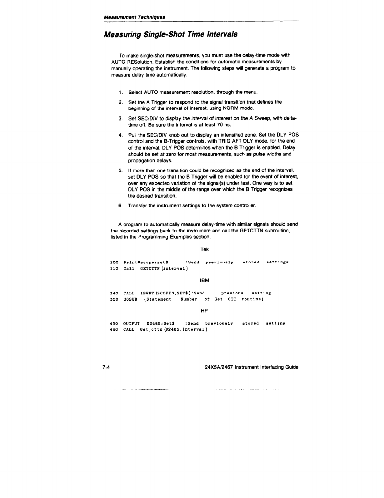
Measurement Techniques
Measuring Single-Shot Time Intervals
To make single-shot measurements, you must use the delay-time mode with
AUTO RESoWion. Establish the conditions for automatic measurements by
manually operating the instrument. The following steps will generate a program to
measure delay time automatically.
1. Select AUTO measurement resolution, through the menu.
2. Set the A Trigger to respond to the signal transition that defines the
beginning of the interval of interest, using NORM mode.
3. Set SEC/DtV to display the interval of interest on the A Sweep, with delta-
time off. Be sure the interval is at least 70 ns.
4. Pull the SECKIIV knob out to display an intensified zone. Set the DLY POS
control and the B-Trigger controls, with TRIG APT DLY mode, for the end
of the interval. DLY POS determines when the B Trigger is enabled. Delay
should be set at zero for most measurements, such as pulse widths and
propagation delays.
5. If more than one transition could be recognized as the end of the interval,
set DLY POS so that the B Trigger will be enabled for the event of interest,
over any expected variation of the signal(s) under test. One way is to set
DLY POS in the middle of the range over which the B Trigger recognizes
the desired transition.
6. Transfer the instrument settings to the system controller.
A program to automatically measure delay-time with similar signals should send
the recorded settings back to the instrument and call the GETCTTN subroutine,
listed in the Programming Examples section.
Tek
100 Print#scopelaett
110 Call CETCTTN(interva1)
!Send previously etored eett1ngs
IBM
540 CALL IBWRT(SCOPE%,SET$)'Send
350 GOSUB (Statement
Number or Get CTT routine)
preVlOllS setting
HP
430 OUTPUT
440 CALL Get-cttn(D2465,Interval)
7-4
DZ465;Setl ISend previously stored Betting
24X5A/2467 Instrument Interfacing Guide

Measurement Techntques
Measuring Peak Voltages
Trigger coupling should be set at DC and verttcai input coupling should be set
at DC. Always display the signal with at least three divisions of amplitude. Larger
amplitudes, up to twenty divisions, provided each peak of the signal Is within ten
divisions of ground, generally give more repeatable peak voltage measurements.
Set the A Sweep at any convenient speed faster than 10 msldivislon, for any slgnai
period less than 20 ms. For signal periods up to 200 ms, set SEClDiV slower than
0.25 times the period. SEC/DIV settings from 50 ms to 500 ms allow measuring
the peaks of signals having periods up to 200 ms.
Manually set the instrument for the measurement and store the settings in the
controller with an ‘iiset?” query. An automatic test routine should return the
settings to the scope and then call the GETPEAKS subroutine, listed in the
Programming Examples section.
Tek
100 Prlnt#seopelaetS I Send PreViOUBly stored settings
Call
110
GETPEAKS(hlSh.
120 pktopk=hiSh-low
1OlI)
IBM
220
CALL IEWRT (SCOPEX.SETS)'Send prOViOU0 setting
230
GOSIJB (Statement Wumber of Get Peaks routine)
PKTOPK- HIPEAK-LOPEAK
240
HP
120
OUTPUT D2465:SetS ISsad previously
130
CALL Get-peaks (D2485.Hipsak.Lopeak)
140
Pktopk = Hlpsak-Lopsak
stored setting
24X5A12467 instrument interfacing Guide 7-5

Measurement Techniques
Measuring Rise and Fall Times
A system comprising a controller and an oscilloscope with CTT and GPIB can
measure transition times automatically, on repetitive signals. The system measures
peak voltages and calculates the appropriate trigger levels for delay
measurements, The trigger levels define points on a signal transition from which
delay times are measured. Transition time is the difference between delay times
with the trigger level set at 10% and 90% of the transition amplitude.
Waveform variations and trigger system distorttins make transition time
measurements less accurate than other time measurements. Even so. these
measurements are adequate to characterlze or verify many devices and systems,
especially if the measurements are optimized by the techniques described here.
The best procedure for measuring rise trme or fall time depends on signal
characteristics. The oscilloscope requires 70 ns after the A Trigger before enabling
the B Trigger, with delay set at minimum using either the DLY POS controt or a
DELAY -0.05 command.
l
If a pulse is wider than 70 ns. the A Trigger and the 8 Trigger can operate on
opposite slopes of the pulse.
l
If the pulse is shorter than 70 ns, the 6 Trigger should be set for the same
slope as the A Trigger. The A-Sweep rate and delay should be set so that
the B Trigger operates on a later cycle of the signal.
l
If the high and low states of the pulse are at least 10 microseconds long, the
necessary signal delay to the B Trigger can be supplied by using HF AEJ
coupling. On such low-frequency signals, Using HF REJ and same-slope
triggering gives faster results and better resolution than opposite-slope
triggering with DC coupling.
Depending on signal characteristics, use one of the following procedures to
manually set the instrument for a delay measurement. Always display the signal
with at least three divisions of amplitude. Larger amplitudes, provided each peak of
the signal is within ten divisions of ground, generally give more repeatable
measurements. These measurements are made by the trigger and time-interval
counter systems and are independent of the display.
l
For pulses more than 70 ns wide:
1. Set A Sweep to display the rising and falling edges of the signal, wrth
the A Trigger set for the transition of interest, and delta-time off.
7-6 24X5A/2467 Instrument Interfacing Guide

Measurement Techniques
2. Pull the SEClDlV knob out to display an intensified zone and set DLY
POS for zero delay.
3. Select TRIG AFT DLY mode for the B Trigger. Set B-Trigger SLOPE
opposite from the A Trigger. Set B-Trigger SOURCE and LEVEL to
trigger the intensified zone at the pulse transition after the transition of
interest.
. For pulses shorter than 70 ns:
1. Set A Sweep to display one cycle of the signal, with A Trigger set for
the transition of interest, and delta-time off. SEC/DIV should be set at
10 nsldiv for any signal with a period less than 100 ns.
2. Pull the SEC/DIV knob out to display an intensified zone and set DLY
POS at minimum.
3. Select TRIG AFT DLY mode and DC coupling for the B Trigger. Set B-
Trigger SLOPE the same as the A Trigger. Set B-Trigger SOURCE and
LEVEL to trigger the intensified zone at a later pulse transition than the
transition of interest.
4. While holding the A/B/MENU button depressed to access the A-Trigger
controls, vary LEVEL. Verify that the B Trigger responds to the same
signal cycle with any A-Trigger LEVEL setting that could be used. If the
intensified zone jumps from one cycle to another, reset DLY POS to
enable B Trigger at a time such that the intensified zone tracks the
same transition for all usable settings of A-Trigger LEVEL. Set DLY
POS in the middle of the range that produces proper operation.
9 For pulses with both high and low states at least 10 microseconds long:
Set the oscilloscope controls to display the signal. Set the A Sweep at
1 microsecond/division. Set the A Trigger for the transition of interest.
Set delta-time off.
Pull the SEC/DIV knob out to display an intensified zone and set DLY
POS for zero delay.
Set the B Trigger to TRIG AFT DLY Mode, the same SLOPE and
SOURCE as the A Trigger, and HF REJ Coupling. Then press INIT@
to set the B-Trigger Level.
24X5Al2467 Instrument Interfacing Guide 7-7

Measurement Techniques
l
For pulses of any width and period, with an auxiliary pulse occurring at least
70 ns after the transition of interest:
1. Display the transition of interest on one vertical channel and the
auxiliary pulse on another channel. Set A-Trigger SOURCE and SLOPE
for the transition of interest. Set delta-time off.
2. Pull the SECJDIV knob out to display an intensified zone and set DLY
POS for zero delay.
3. Select TRIG AFT DLY mode and DC coupling for the B Trigger. Set BTrigger SOURCE and LEVEL for the auxiliary pulse. If necessary,
readjust DLY POS to position the intensified zone at the earliest
possible transltion of the auxiliary pulse and such that the intensified
zone remains on the same transltion for all settings of A-Trigger Level
(while holding A/B/MENU for access to the A Trigger).
Transfer the appropriate instrument settings to the system controller.
To automatically measure transition time:
1. Return the appropriate, recorded instrument settings and measure
positive and negative peaks of the signal, using a procedure such as the
followmg. See the Programming Examples section for the GETClTN
and GETPEAKS subroutines.
Tek
100 Print#scope:set$ ! Send previously stored settings
110 call CETPEAKS(hipeak. lopeak )
120 pktopk=hipeak-lopeak
IBM
220 CALL IBWRT (SCOPE %. SETS ) 1 send
previous setting
250 COSUB (Statement Number of Get Peaks routine)
240 PKTOPK= HIPEAK-LOPEAK
HP
120 OUTPUT D2465;SetS ! Send previously stored setting
130 CALL Get-peaks (D2465,Hipeak.Lopeak)
140 Pktopk = Hipeak-Lopeak
24X5Al2467 Instrument Interfacing Guide

Measurement Techniques
2. Set the B-Trigger level to the average of the positive and negative peak
values, using the BTRIGGER INIT command.
Set the A-Trigger level to the negative peak value plus 10 percent of the
3.
difference between the positive and negative peaks.
Tek
250
10r=O.l !Typically lO%,
260 Print#scope:'btr
level:"; lopeak+lor'pktopk
!Send 1OW level to the A Trigger
may
be changed
IBM
1100
1110
1120
L0a=0.1
ATRLEV$="ATR
CALL IBWRT (SCOPE%, ATRLEVS)
LEVr "+STR$ (LOPEAR+LOW*PKTOPK)
HP
1100
1110
270
Low=0.1
OUTPUT 02465: "atr
4
Read the delay time.
Call getcttn(delayl)!Get
levr
“k
VALS (Lopeak + Lo.*Pktopk)
first measurement
5. Set the A-Trigger level to the negative peak
value
plus 90 percent of the
difference between the positive and negative peaks.
280 high=O.B !Typically
Print#scope:“atr level: -:lopeak+high'pktopk
290
Read the delay time.
6.
300 Call
getcttn
(deleyZ)!Get
!Send 90% level to
90%.
may be
second measurement
7. Subtract the second reading from the first to obtain rise time.
changed)
A-trigger
310 Risetime=delayl-delayZ!Delay difference
If the A-Trigger SLOPE is negative. the result will be negative and the
measurement WIII be the negative of fall time.
24X5A12467 Instrument Interfacing Guide
7-9

Mt?ffsuremt?nt T8chniques
Trigger Level Compensation
Because of signal distortions in the trigger system, a transition time measured
with calculated 10% and 90% thresholds
of the waveform, especially with fast transitions. Any discrepancy can be treated
as an error in the measured peak voltages, which correspond approximately to the
0% and 100% values of the transition region. Even with this discrepancy, transition
times of similar signals with similar repetition rates can be compared to a reference
with enough accuracy for most applications. For good accuracy, use the CTT and
trigger system to measure transition times comparatively, and use the cursors to
determine actual values.
1. Carefully measure a transition time using the delta-time cursors.
2. Measure the same transition time by the appropriate procedure. above.
3. Estimate new values for the ‘low’ and “high” variables (initially 10% and
90%) as required to adjust the CT and trigger measurement to agree with
the cursor measurement. Adjust “high” if the transition is much slower at
the high end than at the low end, such as an exponential step. Adjust ‘low”
if the transition is much slower at the low end. If one peak has a large
overshoot, adjust the variable near that peak. If both peaks are severely
overshot, both “high’ and “low” should be adjusted. If the transition slew
rate is constant and pulse distortions are less than 5%, adjust onty ‘high”
for rise time or “low” for fall time. Repeat the measurement, estimation of
new values, and the trigger-level adjustment steps until the desired
accuracy is achieved.
may
not agree with a direct measurement
Programming Examples
Each of the examples assumes the following declaration statement or an
equivalent. For illustration, the GPIB address of the oscilloscope is assumed to
be 1.
7-10 24X5A12467 Instrument Interfacing Guide

Measurement Techniques
Tek
10 scope=1 ! Assuming GPIB adrs is 1
IBM
ior
for
Scope
10 SCOPE$="o2465" !String name Of scope
20 CALL IBFIND(SCOPE$.SCOPE%) !Returns with
30 IF IBSTA%<O
THEN (Statement Number of ERROR ROUTINE)
! GPIB driver must = name given
! in IBCONF.
! SCOPE% I/O address
! seen through CPIB driver.
! I/O statements use SCOPE%
HP
10 D2465 = 701 !I/0 pointer
!address
= 700
plus Scope
The system controller can “learn” the oscilloscope settings for a given test, using a
routine similar to the following.
Tek
20 Dim set$ to 180 !Array to store settings
. * .
. . .
110 Print#scopa:"llsetY"!Ask for settings
120 1nputffscope:set.T !Put setup into set$
IBM
query
Ior settings
binary setting
string once.
into SETS
20 SETS=SPACES (160)
30 SETQUER$='~lsetY
. . .
. . .
110 CALL
120 CALL IBRD(SCOPE%,SETS)'Put
IBWRT (SCOPE%,SETQUERS)*AS~
'String to store
'Define
set
setup
HP
20
Dim
. , .
SetSll801
. . .
110 OUTPUT D2465;‘11set?"!Ask for settings
110 ENTER D2465;Setf !Store in Sets
!Array to store settings
24X5A12467 Instrument Interfacing Guide
7-11

The ‘Ilset?” query transfers binary control data to save time. If your controller
will not support eight-bit binary data transfers, you can use an ASCII transfer. To
store instrument settings as ASCII data, dimension the set$ array, above, to 1200
bytes and replace ‘llset?” with ‘set?“.
The instruments, interacting with an operator, can measure time with cursors,
delay time, or delta-delay time. With the CTT, they also can measure delay time or
delta-delay time without an operator, using TRIG AFT DLY and TRIG A DLY STrigger modes.
7.12 24X5Al2467 Instrument Interfacing Guide

Table 7-l
Delay Time and Della-Delay Time
Measurement
Techniques
Mode Query
Cursor At or l/At
Delta-Delay Al
or
l/At
Delay
Delta-Delay At
l/At
or Delay, with
Cl-l
or
TDELTA?
TDELTA?
DELAY?
CTSEND?
Conditions and Results
Requires [l] A-Sweep or B-Sweep display
(not ALT or INTEN) [2] cursors on with
1lAt [3] operator to set DLY POS control.
Gives time or frequency in seconds, hertz,
percent, or degrees. If cursors are active,
DELTA? MODE query returns DELTA
MODE:CTIME or DELTA
MODE:CPERTIME. In the special case
where cursors are active with B-Sweep
delayed by events (with ClT) the last three
characters of a MESSAGE? query are BSW.
Requires [l] INTEN. ALT, or B-Sweep
display [2] RUN AFT DLY B-Trigger mode
[3] operator to set A REF and A controls.
Gives time or frequency in seconds, hertz,
percent, or degrees. (Invalid result is
returned with TRIG AFT DLY.) If
is active without cursors, a DELTA? MODE:
query returns DELTA MODE:TIME OT
DELTA MODE:PERTIME.
Requires [1] INTEN, ALT, or B-Sweep
display [2] RUN AFT DLY B-Trigger mode
[3] operator lo set DLY POS control. Gives
delay setting in divisions which must be
multiplied by A-SEC/DIV to determine delay
time. (Invalid result is returned with TRIG
AFT DLY.)
Requires [l] INTEN, ALT, or B-Sweep
display [2] TRIG AFT DLY or TRIG A display
[2] TRIG AFT DLY or TRIG
display (21 TRIG AFT DLY or TRIG A or
Delay, DLY B-Trigger mode [3] appropriate
with ClT settings to frame desired
measurement 14) selecting
INTEN or ALT mode or with DELTA
MODE:TIME or DELTA MODE:PERTIME
command. Alternative to requirement [2] is
RUN AFT DLY B-Trigger mode and operator
to set A REF and A controls. Gives time or
frequency in seconds or hertz.
At
or l/At
At
or l/At in
At
At or
or l/At
24X5A/2467 Instrument Interfacing Guide
REV OCT 1986
7-13
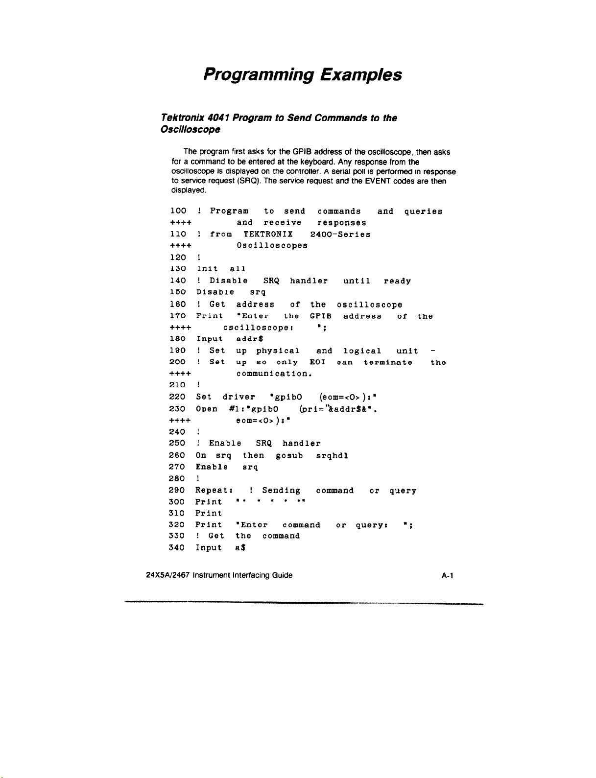
Programming Examples
Tektronix 4047 Program to Send Commends to the
Oscilloscope
The program first asks for the GPIB address of the oscilloscope, then asks
for a command to be entered at the keyboard. Any response from the
oscilloscope is displayed on the controller. A serial poll is performed in response
to service request (SRQ). The service request and the EVENT codes are then
displayed.
100 ! Program to send commands and queries
++++ and receive responses
110 ! from TEKTRONIX 2400-Series
++++ Oscilloscopes
120 !
150 Init all
140 ! Disable SRQ handler until ready
150 Disable
160
! Get address
170 Print ‘Enter the CPIB address of the
++++ oscilloscope:
180 Input addr$
190 ! Set up physical and logical unit 200
! Set
++++ communication.
210 !
220 Set driver “gpib0 (eom=<O>)r”
230 Open #lz’gpibO (pri=“&addr$C”,
++++ eom=<O>)r”
240 !
250 ! Enable SRQ handler
260 On srq
270 Enable
280 !
290 Repeat: ! Sending command
500 Print n *
310 Print
320 Print “Enter command or query:
330 ! Get the command
340 Input a$
srq
up so only
then
gosub
srq
l
* * *#
of the oscilloscope
“;
EOI can terminate
srqhdl
or query
“;
the
24X5A/2467 Instrument Interfacing Guide
A-l

Appendix A
! Send command or query
350
360
Print #lra$
370
! Get response
380
DIM resp$
390 Input
to
#1 rresp$
if there is any
2000
to scope
400 Print
410 ! If no response
++++ another
420
If len (resp$)=O
430
! If yes
then print the
440 Print ‘Response
then prompt for
command
then got0
repeat
response
from the oscilloscope
+-i-t+ iSI ”
450 Print
460
Goto
reap8
repeat
470 Srqhdlr ! routine to handle the
480 Poll stb,dev
490 Print #devr’event?”
500
! Get event
Input #devrevent
510
number
520 Print “Instrument #‘;dev;*status
++++ byte=n;stb;w
,event=w;event
530 Resume
Tektronix 4047 Program to Calibrate Trigger Levels for
Transition Time
!A Tektronix
10
-l-t++
20 ! for
30 ! 30
40 !
50
!Noter
to Adjust Trigger Thresholds
Transition
w++++* in place of line number
++++ indicates printed break
! in
60
t+++
70 !
80
long
without - ++++. or break.
Compress ! 4041 housekeeping
90 Scope=1 !Use actual GPIB adrs of
++++
100
True=1
Oscilloscope
110 False=0
120
Integer
count
4041
BASIC Program
Time Measurements
June 1986
line, which must be entered
sw
A-2
. “.*._ _.‘.,,,, x ..-, -.
ZiX5A12467 Instrument Interfacing Guide

Appendix A
130
140
150
160
++++
170
++++
Count=0
Risetime=O
Print
Print “Execute this procedure and
program to find the
Print “high and low thresholds for
transition time measurements.”
180 Print
190 Print “Repeat
the procedure to find
++-I-+ the opt imum thresholds
200
210
220
++++
230
240
+t++
250
++++
260
270
+++t
280
++++
290
tttt
300
t-l-++
310
320
++t+
330
++++
340
350
++++
360
370
++t+
360
+t++
390
Print “each dissimilar
Print
Print “1. Connect
oscilloscope to
controller IEEE-488 bus.”
Print
Print “2. Carefully
transition time
Print ” Use
10% and 90% or 20%
measure
with cursors.”
and 80% as appropriate.”
Print
Print “3. Manually set the scope to
measure the transition of”
Print ”
control settings
Print ” used
interest, with the same
that will be”
in the automatic test.
Review ““Measuring Rise”
Print ” and Fall
Times”” to
determine the best settings.”
Print
Print “4. Enter transition time,
measured in step
2,”
Print ” in exponent ial
5.43e-9.”
Print
Print ” Use minus time for fall
time, eg. -32.7e-6.”
Print
Input prompt “Transition
“#actual
Wbyte dcl ! Send Device
to GPIB
Highok=true
opt imum”
for”
signal. ”
form. eg.
Time :
CLear message
24X5A12467 Instrument Interfacing Guide
A-3

Appendix A
400 Lowok=true
410
++++ adjusted
420
Low=O.l !Typically 10%. may be
later.
High=0.9 !Typically 90%. may be
++++ adjusted later.
430 Print
440 Print "Enter
""y<RET!JRN>"'
for
ii++ ""yes,"" or '.n<RETURN>""
ii++
for
"lnO*"".
450 Print
460 Input prompt 'Are
++++ threshold other than
using a low
YOU
10%Pgransner$
470 If answer$<>"y' then got0 ask90
480 Input prompt "Enter
low threshold
++++ value as decimal fraction: "IlOW
490
500 If lOW>0.9 then
510 AskSO: input prompt 'Are
If 10w<0.02 then 1ow=O.l
low=O.l
YOU
++++ using a high threshold other than
ii++ 90%?'ranswer$
520 If answer$<>'y"
then got0 askx
530 Input prompt "Enter high threshold
++++ value as decimal
540 If high<O.l then
550
If highs0.98 then high=0.9
high=0.9
fraction8 "thigh
560 Askxr print -Initial low
++++ threshold=';lor;" Initial high
++++ threshold=.;high
570 Print "Is the transition OBVIOUSLY
++++ slower near the high than
++++ near the low?
580
Input ansrerS
590 If answer$="y" then
If
600
answer$="y" then got0 aberr
610 Print "IS the transition
";
highok=false
OBVIOUSLY
++++ slower near the low than
++++ near the high?
l :
620 Input ansrer$
630 If answer$="y. then lonok=false
640 Aberrr !
650 Print "Do both high and
low
levels
++++ have less than 5%'
4-4
24X5/\/2467 Instrument Interfacing Guide
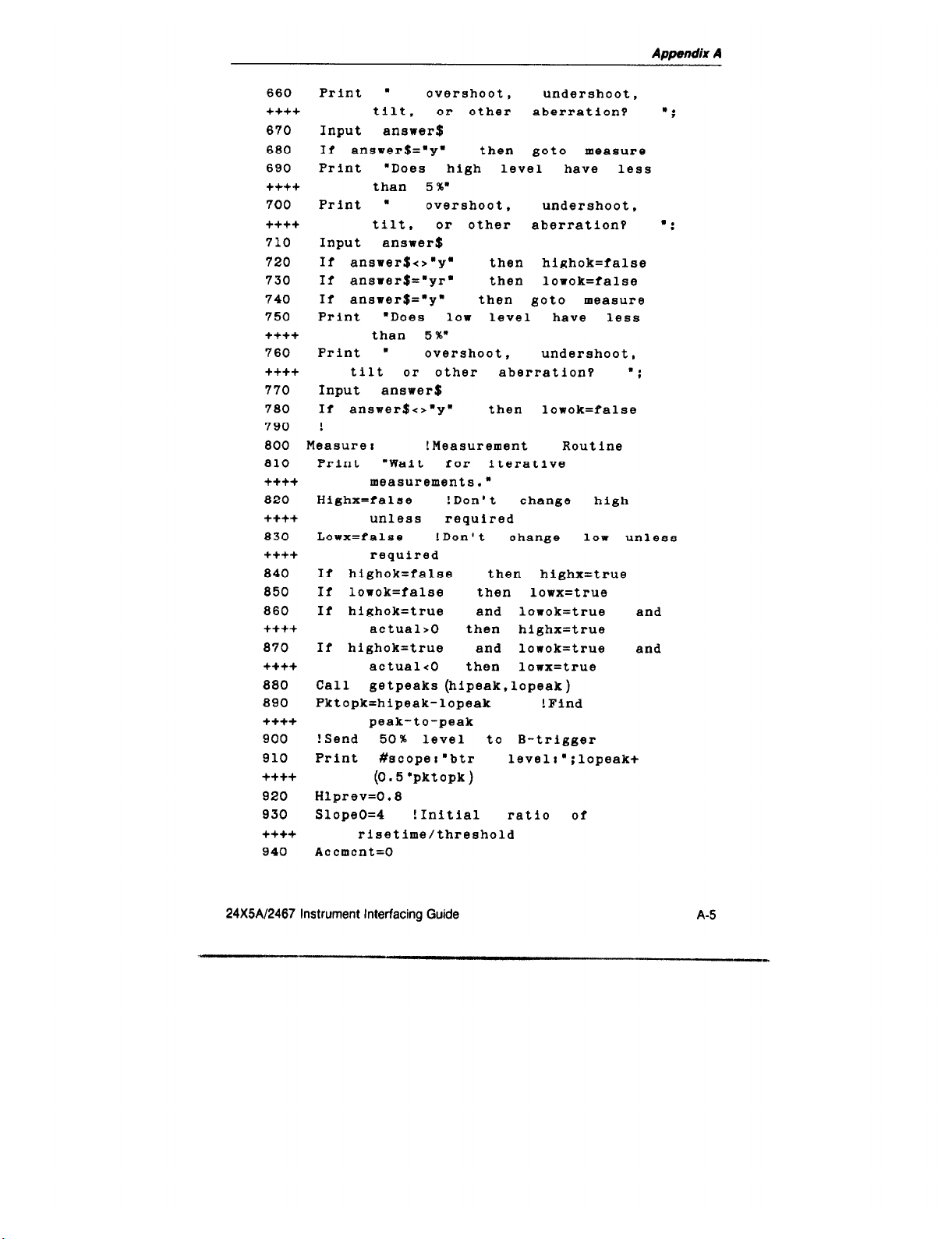
Appendix A
660
++++
670
680
690
++++
700
++++
710
720
730
740
750
it++
760
++++
770
780
790
800 Measure:
810 Print ‘Wait
++t+
a20
++++
830
++tt
840
850
860
Print .
tilt, or other
overshoot, undershoot,
aberration?
Input anawer$
If answer$=.y. then got0 measure
Print “Does high level have less
than 5%’
Print ” overshoot. undershoot,
tilt, or other
aberration?
Input answer$
If answer$<>“y” then highok=false
If answer$=.yr* then lorok=false
If answer$=“y* then got0 measure
Print *Does low level have less
than 5%”
Print W overshoot, undershoot,
tilt or
other aberration?
Input answer$
If answer$<>“y” then lowok=false
!
!Measurement Routine
iterative
for
q easurements.n
Highx=false !Don't change high
unless required
Lowx=false !Don't change low unless
required
If highok=false then highx=true
If lowok=false then lowx=true
If highok=true and
lonok=true and
++t+ actual*0 then highx=true
870
++++
880
890
t+++
900
910
If highok=true and lowok=true and
actual<0 then lonx=true
Call
Pktopk=hipeak-lopeak
getpeaks (hipeak,lopeak)
! Find
peak-to-peak
! Send
Print
50% level
#scoper’btr
to B-trigger
levelt”;lopeak+
t+++ (0.5 ‘pktopk)
920
930
Hlprev=O.8
SlopeO=4 ! Initial ratio of
+tt+ risetime/threshold
940 Accmcnt=O
l ;
“;
“:
24X5A/2467 Instrument Interfacing Guide
A-5

Appendix
A
950
Riseaccm=O
960 Hlaccm=O
970 !
980 Againr ! Iteration Loop
990
1000
+ttt
1010
1020
H-t+
1030
++++
1040
1050
+++t
1060
1070
t++t
1080
++tt
ttit
1090
+t++
1100
++++
++++
1110
++++
++++
1120
++t+
1130
1140
++++
1150
+tt+
1160
tttt
1170
1180
1190
1200
Count=count+l
Print
#scoper”atr
level:“;
lopeaktlow l pktopk
! Send low level
Call
getcttn (delayl)
to A-trigger
delay reading
Print #scoperaatr level : “;lopeak
+high ‘pktopk
! Send
high level
to A-trigger
Call getcttn (delay2) ! Get 2nd
delay reading
Riseprev=risetime
Risetime=delayl-delay2 ! Delay
difference
If risetime/actual>0.99 and
risetime/actualcl.Ol
got0 finish
If count>19 then got0 finish
!Can’t converge within 1%
If count>1
+abs ((risetime-
then
riseaccm=riseaccm
riseprev )
/risetime)
If c0unt>1 then hlaccm=hlaccm
+abs ( (high- low-hlprev)
I (high-low ) )
If hlaccm>0.02 then slopeO=
riseaccm/hlaccm
Slope=slopeO
If highx=true
lowx=true then
and
slope=slope ‘2
Change= (high-low) * (actual/risetime
-1) /slope
If hlprev>0.95 and high=0.96 and
10w=0.02
then got0 finish
Hlprev=high-low
If highx=true then high=high+change
If lowx=true then low=low-change
If highzO.96 then high=0.98
! Get 1st
then
A-6
24X5N2467 Instrument Interfacing Guide

Appendix A
1210 If 10w<0.02 then low=0.02
1220 If (low+O.l)>high then got0 finish
++++ !Invalid "actual"
1230 If high=0.98 then 1owx=true
1240 If low=0.02 then highx=true
1250 Goto again
1260
!
1270 Finish: !
1280
Print
1290 Print count;" iterations"
1300
Print "Use
these
new values for high
++++ and low with similar signals."
1310 Print " New value for high =
++++ ";high
1520
Print " New
value for
low =
++++ ";1ow
1330 Print "Measured Rise Time (Fall Time
++++ if
1340 If count>19 then
Negative)
= ";risetime
print
"Verify
++++ risetime measurement value.'
1350
1360 Print
Print
"Entered (target) Transition
++++ Time = ";actual
1370 Print
1380
++++
If (high-low)<0.2
. t..
ENTERED TRANSITION TIME
then print
++++ OUT OF RANGE. ***I
1390 If high=0.98 and 10w=0.02 then print
++++
++++
. ***
ENTERED
TRANSITION TIME OUT OF RANGE. I**"
1400 stop "-- Enter *"run"" to do another
++++
threshold optimization."
1410 End
1420
++++
Sub getpeaks (var
local timeref.resu1t.g
hipeak,lopeak)
1430 !Set A-trigger to INIT @ 50% for peak
++++
1440
Print
measurement cycle
#scope:"atr init50"
1450 timeref=ask ("time") !Starting time
1460 Waitpksc Input #scope prompt "atr?
ii++ trigd"rresult$ !Triggered?
24X5A12467 Instrument Interfacing Guide
A-7

Appendix A
1470
++++
1480
+t+t
+++t
1490
1500
++t+
1510
+ttt
1520
1530
1540
+t+t
1550
++++
1560
1570
it++
1580
1590
1600
1610
+++t
1620
1630
1640
1650
++++
1660
++++
1670
+t+t
1680
++t+
1690
tttt
1700
tttt
1710
If result$=‘ATR
found ! Peaks
If timeref+ZO*ask (‘time.)
waitpks
set
since start
TRIGDION;” then got0
found
then got0
! Loop
if < 20
!Else
Print n*** FAULTY PEAK VOLTAGE
MEASUREMENT
Print “Check oscilloscope
l l l
20
SECOND TIMEOUT”
settings
and signal source .w
stop
w-- Enter ‘Drun’a to try again.”
:
Found 8
Input #scope prompt “atr?
!
!Typical result string-- ATR MINI8
!Extract low peak from result string
Lopeak=val (results )
!Extract high peak from result string
Hipeak=valc (result$.pOS (results.
Return
End
Sub getcttn (var cttcount )
Long cttcount !To accept up to le99
Print #scoper’ctt reset” !Discard
Waiting8 input #scope
If cttcount=O then got0 waiting
Input #scope prompt “cts?“:cttcount
If cttcount<l.OE+S then return
! Else
! Ask instrument ror peaks by
A-trigger query
mini,
max.:resultS
-489E-3,MAXs496E-3;
“MAX’,l))
error code
stale measurements
prompt .ctr?”
lcttcount
! Hang
!Get
until ready
reading from scope
scope ready?
!Is
!>1ES count indicates error
A-8
24XiAl2467 Instrument Interfacing Guide

Appendix A
1720 Print 1*** FAULTY TIME OR COUNTING
+ttt MEASUREMENT *** Error
+t++ Code: ";cttcount
1730
t++t
Print 'Check of3cilloscope
signal
and
source:
settings
1740 stop '-- Enter narunn* to try again."
1750 End
IBM PC/X T/A T Program to Calibra tt
?
Trigger Levels for
Transition Time -
10 'XTNLEV.BAS-- a BASIC
tttt IBM PC/XT/AT
20 ' Tektronix GPIB User
+++t Utility (GURU
30 '
40 ' National Instruments
tttt
Instrumentation Interface
50 'To Adjust Trigger Thresholds for
+tt+ Transition Time Measurements
60 ' with the Tektronix 24X5A and 2467
+t++ Oscilloscopes with CTT
70 ' 30 June 1986
80 'NOTE: .++++a in place of a line number
tt+t
indicates that
90 ' separately printed
ii++ joined. The *ii++"
100 ' symbols must not be entered.
110 'INITIALIZE
120 KEY OFF I SCREEN 0 I LOCATE
t+++ : CLS
130 'The following 6 lines load the
tt+t utilities
140
+t++
'are
necessary
This should be done
for program operation.
150 'at the beginning of every application
it++ program.
160 CLEAR 10000,59665!
170 IBINITl = 59665!
program for the
with
8
Resource
)
01
IEEE-488
lines
into memory
must be
l.l,O
that
24X5Al2467 Instrument Interfacing Guide A-9

Appendix A
180
190
200
IBINIT2 = IBINITl + 3
BLOAD "bib.m" ,IBINITl
CALL IBINIT~ (IBFIND,IBTRG,IBCLR,
++++ IBPCT,IBSIC.IBLOC,IBPPC,IBBNA,
++++ IBONL,IBRSC,IIBSRE.IBRSV,IBPAD,
t+t+ BSAD,IBIST,IBDMA.IBEOS.IBTMOI
++++
210
IBEOT,IBRDF,IBWRTF)
CALL IBINITB(IBCTS,IBCAC,IB~~AIT,
++++ IBPOKE,IBWRT,IBWRTA,IBCllD,
tt+t IBCMDA,IBRD,IBRDA,IBSTOP.IBRPP,
t+++ IBRSP,IBDIAG,IBXTRC,IBRDI,
tttt IBWRTI.IBRDIA.IBWRTIA.IBSTA%,
++++ IBERR%,IBCNT%)
220 '
230 'Use this program
only
ior
system
ttt+ setup and calibration.
240 '
250 SCOPE$="o2465"
'The
same name must
+tt+ be assigned with IBCONF
260 '
270 TRUE = 1 : FALSE = 0
tttt 'Initialize logical values
280 PRINT
290 PRINT*Execute this procedure and
tt+t program to find the optimumg
300 PRINT 'high and low thresholds
for
++++ transition time measurements."
310 PRINT
320 PRINT"Repeat the procedure to find the
tt++ optimum thresholds'
330 PRINT-for
each
dissimilar
signal."
340 PRINT
350 PRINT"1. Connect oscilloscope
++++ IEEE-488 bus and
360 PRINT'
++t+ must
Primary
equal
the
configure
address
of the scope
to
system."
370 PRINT" address assigned to 02465
tttt with IBCONF."
380 PRINT
390 PRINT"2. Carefully measure transition
tt+t time
with
curs0rs.g
A-10 24X5A/2467 Instrument Interfacing Guide

Appendix A
400 PRINT'
Use
10% and 90% or 20% and
++++ 80% as appropriate."
410 PRINT
420 PRINT"3. Manually set the scope to
++++ measure
430 PRINT- interest, with
++++
control settings that will be"
the transition o?.
the
same
440 PRINT* used in the automatic test.
++++ Review '"Measuring Rise
450 PRINT" and Fall Times" to determine
++++
the best settings."
460 PRINT
470 PRINT"4Q. Enter transition time,
++++
480 PRINT"
ii++
490 PRINT' Use minus time
measured in step
in exponential
5.43e-9..
eg.
2,.
fOlYll.
for
fall time,
++++ eg. -29.6e-6."
500 PRINT
510 CALL ISFIND (SCOPE$.SCOPE%)
++++ 'Find scope specifier 'scope%'
520 IF IBSTA% < 0 THEN 2360
++++ 'Incorrect symbolic
530 IDTEST$='id?"
540
CALL IBwRT (SCOPE%,IDTEST$) 'First call
++++ to test scope address
550 IF IBSTAZ
++++
< 0 THEN 2360
'Incorrect address
560 CALL IBLOC (SCOPE%)
++++
'User
sets up
scope
570 INPUT'Transition Time: ".ACTUAL
580 CALL IBCLR (SCOPE%)
++++
'Send Device Clear message
++++ to GPIB
590 PRINT
600 PRINT"The LOW threshold is typically
++++
10% (0.1 as a decimal)"
610 PRINT" If this is your low
++++ threshold, just press <Enter>620 PRINT'
Otherwise,
type
in a new
++++ low threshold as a"
name
24X5A/2467 Instrument Interfacing Guide A-l 1

Appendix A
630 INPUT" decimal fraction and
++++
press
<Enter>: ..LOW
640 IF LOW < .02 OR LOW > .98
++++ THEN LOW = .l
650 PRINT
660 PRINT"The
HIGH threshold is typically
++++ 90% (0.9 as a decimal)*
670 PRINT" If this
++++ threshold,
just press <Enter>'
680 PRINT"
++++
high threshold as a9
new
690 INPUT'
++++
IF HIGH < .l OR HIGH > .98 THEN
700
press <Enter>: .,HICH
and
is your high
Otherwise,
decimal iraction
type
++++ HIGH = .S
710 PRINT
720 PRINT'Initial low threshold = ';LOW;
730 PRINT'Initial high threshold = ";HIGH
740 PRINT
750 PRINT"Enter
'Y' for a yea answer, or
++++ 'N' for a no answer.'
760 HIGHX = FALSE
++++ 'Don't change
unless required
770 LOWX = FALSE
++++ 'Don't change unless required
780 PRINT'Ia the transition CLEARLY
++++ slower near the high
++++ near the low?
":
than
790 GOSUB 1620 'Get response
800 IF ANSWR$ = 'Y" THEN HIGHX
= TRUE I
++++ GOT0 840 'Aberrations
810 PRINT'Is the
transition CLEARLY
++++ slower near the low than
++++ near the high?
":
820 GOSUB 1620
830 IF ANSWR$ = 'Y- THEN LOWX
= TRUE
840 'Aberrations
850 PRINT"Do both high and low levels
++++ have less than 5%'
860 PRINT' overshoot, undershoot,
++++
tilt
or other aberration?
l ;
in
a
A-12
24X5Al2467 Instrument Interfacing Guide

Appendix A
++tt
070 GOSUB
880
tilt
or
other aberration?
1620
IF
ANSWR$ = 'Y' THEN
":
t++t GOT0 990 'Measure
890 PRINT"Does the high level have lass
++tt
than 5%"
900 PRINT' overshoot, undershoot, tilt
t+tt or other aberration? ';
910 GOSUB 1620
920 IF ANSWR$ <> "Y" THEN HIGHX = TRUE
930 IF ANSWR$ = "Y' THEN LOWX = TRUE t
tt+t GOT0 990 'Measure
940 PRINT"Does the low level have less
+ttt
than 5%"
950 PRINT" overshoot, undershoot. tilt
t+tt or other aberration?
960
GOSUB
970
IF ANSWRS <> 'Y" THEN LOWX = TRUE
1620
";
980 '
990 'Measurement Routine
1000 PRINT" -- Wait ror
+ttt iterative measurements. --•
1010 IF HIGHX=FALSE AND LOWX=FALSE AND
it++ ACTUAL>0 THEN HIGHX=TRUE
1020 IF HIGHX=FALSE AND LOWX=FALSE AND
++++ ACTUAL<0 THEN LOWX= TRUE
1030
GOSUB
1680
'Get peaks
1040 PKTOPK = HIPEAK-LOPEAK
+tt+ 'Find peak to peak
1050 BTRLEV$="btr lev: "+ STR$ (LOPEAK
tt++ t.S*PKTOPK)'Find
50%
level
1060 CALL IBWRT(~~OPE%,BTRLEV$)
tttt 'Send
1070
IF IBSTA%
50%
level to B trigger
-z 0 THEN 2360
1080 HLPREV = .8
++++ 'Initialize loop variables
1090
SLOPE0 = .25
t-k++ 'Initial ratio of threshold/risetime
1100 RISEACCM = 0
1110 HLACCM = 0
1120 COUNT = 0
24X5A12467 Instrument Interfacing Guide A-13
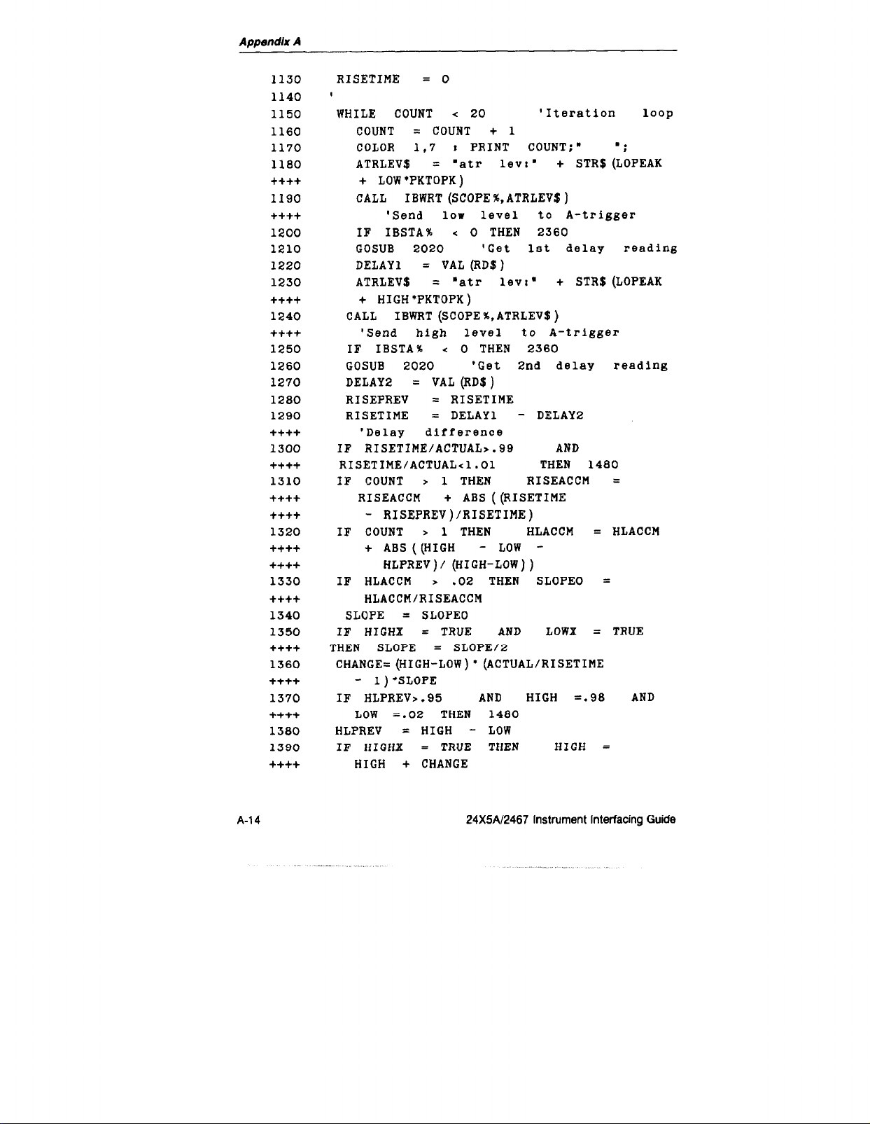
Appendix A
1130
1140
1150
1160
1170
1180
++++
1190
++++
1200
1210
1220
1230
++++
1240
++++
1250
1260
1270
1280
1290
++++
1300
++++
1310
++++
++++
1320
++++
++++
1330
++++
1340
1350
++++
1360
++++
1370
++++
1380
1390
++++
RISETIME = 0
I
WHILE COUNT
COUNT
COLOR 1.7 t PRINT COUNT:"
ATRLEV$ =
< 20 'Iteration loop
= COUNT + 1
‘atr lev:.
+ STR$ (LOPEAK
.:
+ LOW'PKTOPK)
CALL IBWRT(SC~PE%,ATRLEV$)
'Send lor level to A-trigger
IF IBSTA% < 0 THEN 2360
GOSUB 2020 'Get 1st delay reading
DELAY1
= VAL (RD$)
ATRLEV$ = "atr lev:. + STR$(L~PEAK
+ HIGH'PKTOPK)
CALL IBWRT (SCOPE%,ATRLEV$)
'Send high level to A-trigger
IF IBSTA% < 0 THEN 2360
GOSUB 2020 'Get 2nd delay reading
DELAY2 = VAL (RD$)
RISEPREV = RISETIME
RISETIME
= DELAY1 - DELAY2
'Delay difference
IF RISETIME/ACTUAL>.99 AND
RISETIME/ACTUAL<l.Ol THEN 1480
IF COUNT > 1 THEN RISEACCM =
RISEACCM + ABS ((RISETIME
- RISEPREV)/RISETIME)
IF COUNT > 1 THEN HLACCM
= HLACCM
+ AB~((HIGH - LOW -
HLPREV)/ (HIGH-LOW))
IF HLACCM > .02 THEN SLOPE0 =
HLACCM/RISEACCM
SLOPE = SLOPE0
IF HIGHX = TRUE AND LOWX = TRUE
THEN SLOPE = SLOPE/2
CHANGE=(HIGH-LOW)* (ACTUAL~RI~ETIME
- l)*SLOPE
IF HLPREV>.95 AND HIGH =.98 AND
=.02 THEN 1480
LOW
HLPREV = HIGH - LOW
IF HIGHX = TRUE THEN HIGH =
HIGH + CHANGE
A-l 4 24X5N2467 Instrument Interfacing Guide

Appendix A
1400
++++
1410
1420
1430
++++
1440
1450
1460
1470
1480
1490
++++
1500
++++
1510
1520
1530
++++
1540
++++
++++
1550
1560
++++
1570
1580
++++
++++
++++
++++
1590
+-I-++
1800
1610
1620
++++
1630
++++
1640
1650
++++
IF LOWX = TRUE THEN LOW =
LOW - CHANGE
IF HIGH > .98 THEN HIGH = .98
IF LOW
IF (LOW +'.;p2
THEN LOW = .02
> HIGH THEN 1480
'Finish Invalid "actual'
IF HIGH = .98 THEN LOWX = TRUE
IF LOW = .02 THEN HIGHX = TRUE
WEND
‘
'End
iteration
'Finish
COLOR 7,0 I PRINT I PRINT
COUNT:"
ITERATIONS"
PRINT"Use these new values for high
and low rith similar signals..
PRINT" New value for high = ':HIGH
PRINT'
PRINT"Measured
ir Negative)=
IF COUNT > 19 THEN
New
value
iOr
lor = ";LOW
Rise Time (Fall Time
";RISETIME
COLOR
15.4.0:
PRINT “Verify Risetime
measurement value." I COLOR 7.0
PRINT
PRINT "Entered (target)
Transition
Time = ':ACTUAL
PRINT
IF ((HIGH-LOW < .2) OR (HIGH = .98
AND LOW =
COLOR 15.4 I PRINT"
.02)) THEN
..#..
ENTERED
TRANSITION TIME OUT OF RANGE
**#y*r.
PRINT"-- Enter
I COLOR 7.0
'run' to do another
threshold optimization."
GOT0 2400'End Routine
1---------------------------------'Subroutine to Wait for, Receive
and Print Response
ANSWR$ = INKEY$ i IF ANSWR$ =
"' THEN
1630
IF ANSWR$ = lym THEN ANSWR$ = .Y.
IF ANSWR$ = 'Y" THEN PRINT .YES"
ELSE PRINT "NO"
loop
24X5A/2467 lnstrurnent Interfacing Guide A-15

Appendix A
1660
1670
1680
1690
1700
1710
1720
1730
++++
1740
1750
1760
1770
++++
1780
1790
1800
1810
1820
++++
1830
++++
1840
1850
++++
1660
1870
++++
1880
1890
1900
++++
1910
1920
1950
1940
1950
1970
1980
1990
++++
2000
++++
RETURN
1_____----,------------------------
'Subroutine Get peaks
ATRINITSOS = "atr init50.
ATRQUER$ = 'atr? trigd"
ATRPEKSS = 'atr?
max,mini.
I
'Set A-trigger
to INIT @ 50% for
peak measurement cycle
CALL IBwRT (SCOPE%,ATRINITSO$)
IF IBSTA%
< 0
THEN
2360
SENTLEV=TIMER 'START TIMER
CALL IBWRT (scoPE%,ATRQUER$)
'Ask if trigger found
IF IBSTA%
= SPACES (95)
RDO
< 0 THEN 2360
CALL IBRD(SCOPE%,RD$)
IF IBSTA% < 0 THEN 2360
IF MIDS (RD$,INSTR(~,RD$,":~)
+1,2)=“ON”
THEN 1890 'Found
IF SENTLEV +20>TIHER THEN 1770
'Under
20
seconds,
try
COLOR 15.4
PRINT"
PRINT"
**g.*
FAULTY
MEASUREMENT
20
SECOND TIMEOUT"
*I#**.
PEAK VOLTAGE
PRINT'Check settings and
‘run’
to try again."
GOT0 2400'End Routine
1
Found
' Ask instrument
peaks by A-trigger
query
CALL IBWRT (sc~PE%,ATRPEKS$)
IF IBSTA% < 0 THEN 2360
RD$=SPACE$ (95)
CALL IBRD(SCOPE%,RD$)
IF IBSTA%
< 0 THEN 2360
IF IBSTA% < 0 THEN 2360
'Extract high and low
HIPEAK
= VAL (MIDS (RDS,INSTR (1,~~s.
":.)+l,lO))
LOPEAK
= VAL(MID$ (RDS,INSTR(~O.RD$.
'r')+l))
tri3
again
for
peaks
A-16 24X5A12467 Instrument Interfacing Guide

Appendix A
2010
2020
2030
++++
2040
++++
2050
++++
2060
++++
2070
++++
2060
++++
2090
2100
++++
2110
2120
2130
2140
2150
++++
2160
2170
2180
2190
2200
++++
2210
++++
2220
2230
2240
2250
++++
2260
2270
++++
2280
2290
++++
RETURN
I-------------------------------------' Get count Subroutine (equivalent
to GETCTTN subroutine)
CTTRSET$ = 'ctt reset' 'These 4 lines
should appear early in
CTRQUERS = "ctr?' 'the main
program: they are shown
CTSQUERS = 'ots?'
'to indicate
here
the actual string values
EVENT$ = "event?'
'required by the scope.
CALL IBWRT (SCOPE%,CTTRSET$)
'Discard stale measurements
IF IBSTA% < 0 THEN 2360
CALL IBWRT (SCOPE%,CTRQUER$)
'Measurement
available?
IF IBSTA% < 0 THEN 2360
RD$=SPACE$ (95)
CALL IBRD (SCOPE%,RD$)
IF IBSTA% < 0 THEN 2360
CALL IBWRT (sCOPE%,EVENT$)
'Event
query
IF IBSTA% < 0 THEN 2360
EV$=SPACE$ (20)
CALL IBRD (SCOPE%,EV$)
IF IBSTAZ < 0 THEN 2360
IF VAL(MID$ (EV$.INSTR (~,Ev$."
m)+l))
<> 0 THEN 2280
IF VAL (RD$) = 0 THEN 2100
'No measurement
available
CALL IBWRT (SCOPE%,CTSQUER$)
IF IBSTA% < 0 THEN 2360
RD$=SPACE$ (95)
CALL IBRD (SC~PE%.RDS)
'Get reading from scope
IF IBSTA% < 0 THEN 2360
IF VAL (RD~) < lE+09 THEN RETURN
' >=
l.Oe+9 indicates error
COLOR 15.4 'Print error message
PRINT*
COUNTING MEASUREMENT
..#..
FAULTY TIME OR
**#**.
24X5A12467 Instrument Interfacing Guide A-l 7

Appendix A
2300
2310
ii++
2320
ii++
2330
2340
2350
2360
2370
ii++
2380
ii++
++++
++++
2390
2400
2410
2420
++++
2430
PRINT"Error
PRINT'
cod0
Check scope settings and
signal source .'
COLOR 7,0
I PRINT"-----
Enter 'run' to try again.
COT0 2400'End Routine
(___-__-__---------------_--------'Incorrect
= HEX$ (IBSTA%)
S$
symbolic name or address
PRINT ' IBSTA = l ;S$;IBCNT =
";IBCNT%;IBERR = ';IBERR%
IF S$="SOOO"
";SCOPE$;'
is not a valid name."
ELSE PRINT" l ;SCOPE$;" is not
correctly addressed."
)-_-----------------------------'End
Routine
V% = 0 t CALL IBONL (SCOPE%,V%)
COLOR 7.0 I KEY ON : CALL
IBLOC (SCOPE%)
END
':VAL (RDS);
I COLOR 15,4
THEN PRINT'
HP 98XX Program to Calibrate Trigger Levels for
Transition Time
10 ! A BASIC Program for the
-I-+++ Hewlett Packard 98XX
20 !to Adjust
++++ Transition Time Measurements
30 ! with the Tektronix
++++ 24X5A and 2467 Oscilloscopes.
40 ! 30 June 1686
50 GOSUB Setup
++++ !Initialfze and setup crt
60 !
70 !Use this program only for system
ii++ setup and calibration.
80 ! 'NOTE:
++++ number indicates that
90 !' separately printed
++++ must be joined. The
Trigger Thresholds for
" ++++. in place of a line
lines
l ++++.
--w-s"
A-18
24X5A/2467 Instrument Interfacing Guide

Appendix A
100
110
++++
120
++++
150
140
150
++++
160
170
++++
180
++++
190
++++
200
210
++++
220
++++
230
++++
240
++++
250
260
++++
270
++++
280
++++
290
++++
300
++++
310
320
++++
330
++++
! ’
PRINT 'Execute this
symbols must not be entered.
procedure
program to rind"
PRINT 'optimum high and low
thresholds for transition"
PRINT " time measurements.*
PRINT
PRINT "Repeat the procedure to
optimum thresholds"
PRINT " for each dissimilar signal."
PRINT "1. Connect oscilloscope
to controller IEEE-488 bus."
PRINT "2.
transition
Carefully
time
measure
with
cursors..
PRINT . Use 10% and 90% or
20% and 80% or other"
PRINT ' appropriate
PRINT "3. Manually set
to measure
the transi-"
levels.w
the
PRINT " tion of interest, with
the same control setting"
PRINT " that will be used in
the automatic test.
PRINT
l
gaMeasuring Rise and
Review"
Fall Times"' to determine'
PRINT " the best settings.a
PRINT "4. Enter the transition
time measured in step
PRINT " in exponential
ei3.
5.433-g <ENTER>."
2,”
form,
PRINT " fall time is minus,
-29.6E-6 <ENTER>."
w3.
CALL Check-communi(D2465)
!Check bus to scope
LOCAL
PRINT "Transition Time:
02465 !User sets
scope
UP
";
LINPUT Actual$ !E or e
accepted
Actual=VAL (UPCS (Actual$))
!Converts e to E
and
find
scope
24X5A/2467 instrument Interfacing Guide
A-19
 Loading...