

Page 1

Keithley Instruments
Model 2461 in a Seri es 2400 Applicati on
28775 Aurora Road
Cleveland, Ohio 44139
1-800-935-5595
tek.com/keithley
Emulation and Migration Guide
Introduction
This guide provides information about using the Model 2461 as a drop-in replacement in an existing Model
2420, 2425, 2430, or 2440 application. This document refers to these four models collectively as the Series
2400. This docum ent also provides inf ormation about converting existing Ser ies 2400 SC PI cod e to 2461 SC PI
code.
When you use a 2461 in an application designed for one of these instruments, you will not have access to the
extended ranges and other features that were introduced with the 2461. In addition, the options that you can
set from the front panel are more limited.
For example, the highest current range full scale on the Model 2425 is 3 A. The highest current on the 2461 is
10 A. However, when the 2461 is controlled using the SCPI 2425 command set, the maximum range is 3 A.
The 2461 options that are not available with the Series 2400 SCPI command sets include:
Some current and voltage ranges
New trigger model
Ability to run scripts
Front-panel features, including graphing, saving measurement data, and setting up tests
Quick Setups from the QuickSet menu
In addition, source memory can be used, but it is no longer backed up with a battery.
This section describes:
How to select a SCPI command set
Differences between the Series 2400 SCPI command sets in the 2461 and the SCPI command sets
available in the previous Series 2400 products
077162100 / September 2019 *P077162100* 1
Page 2

Model 2461 in a Series 2400 Application Emulation and Migration Guide
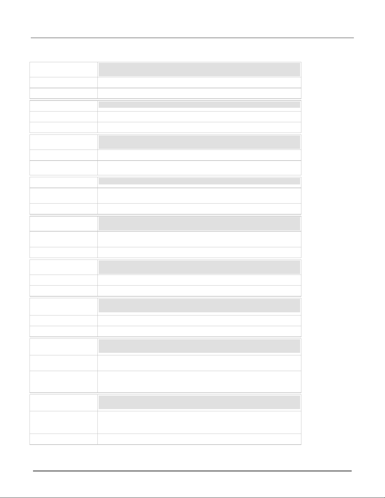
Selecting a comman d set
You can select a command set from the front panel or over the remote interface. After you change the
command set, you must reboot the instr ument.
Using the front panel:
1. Press the MENU key.
2. Under System, select Settings.
3. Select the button next to Command Set.
Figure 1: Selecting a command set
4. Select a command set. You will be prompted to reboot.
5. Select OK.
Using SCPI or TSP remote commands:
Send the command:
*lang SCPIxxxx
Where xxxx can be 2420, 2425, 2430, or 2440. Reb oot t he instr ument.
Front-panel operation with the Series 2400 SCPI command sets
When a Series 2400 command set is selected, the options available through the front panel are limited. For
example, you can observe measurements on the display, but you cannot control the source value using
front-panel displays.
The following topics describe the options that are available when a Series 2400 command set is selected.
2 077162100 / September 2019
Page 3

Model 2461 in a Series 2400 Application Emulation and Migration Guide
Mode Interactive SourceMeter® Instrument Reference Manual.
2
MEASURE view
Green part of the home screen; displays the value of the present
Swipe screen area
Blue part of the home screen. It displays the measured value of the source.
5
Source setting
Displays the current source value.
6
Local button
Cancels remote operation and changes to local operation.
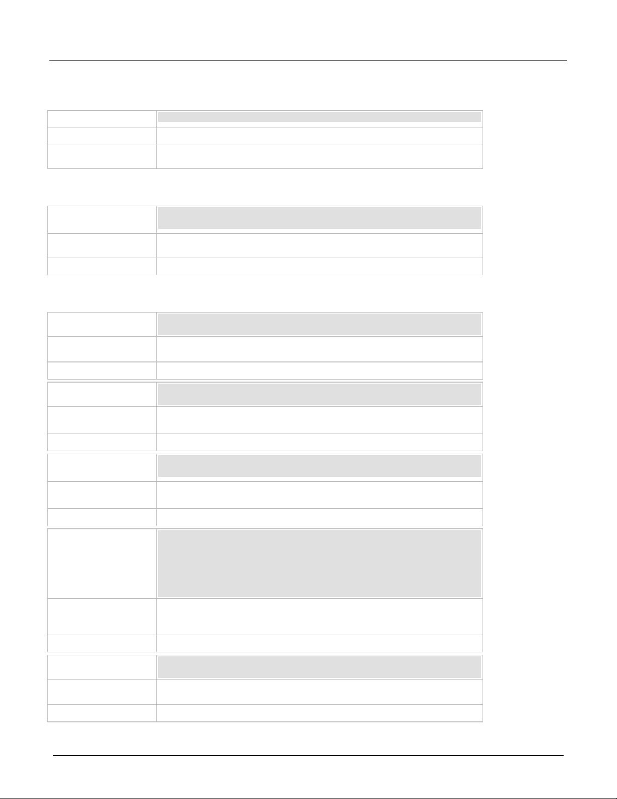
Home screen display
When a Series 2400 SCPI command set is selected, the home screen is the only screen available. There are
no swipe screens.
The options available on the home screen are described here.
Figure 2: Home screen when a Series 2400 SCPI command set is selected
# Screen element Description
1 System status and
event indicators
area
3 Range button Displays the current measure range. Select the button to change the range.
At the top of the home screen. These indicators provide information about the
present state of the instrument. Some of the indicators open up a dialog box
with more information or a settings menu when selected.
For details, see "Status and event indicator s" in the Model 2461 1 kW Pulse
measurement.
Status and error indicators when a command set is selected
The indicators at the top of the home screen contain information about instrument settings and states. Some of
the indicators also provide access to instrument settings.
Select an indicator to get more information about the present state of the instrument. You can also select the
indicators by turning the navigation control to select an indicator and then pressing ENTER.
077162100 / September 2019 3
Page 4

Model 2461 in a Series 2400 Application Emulation and Migration Guide
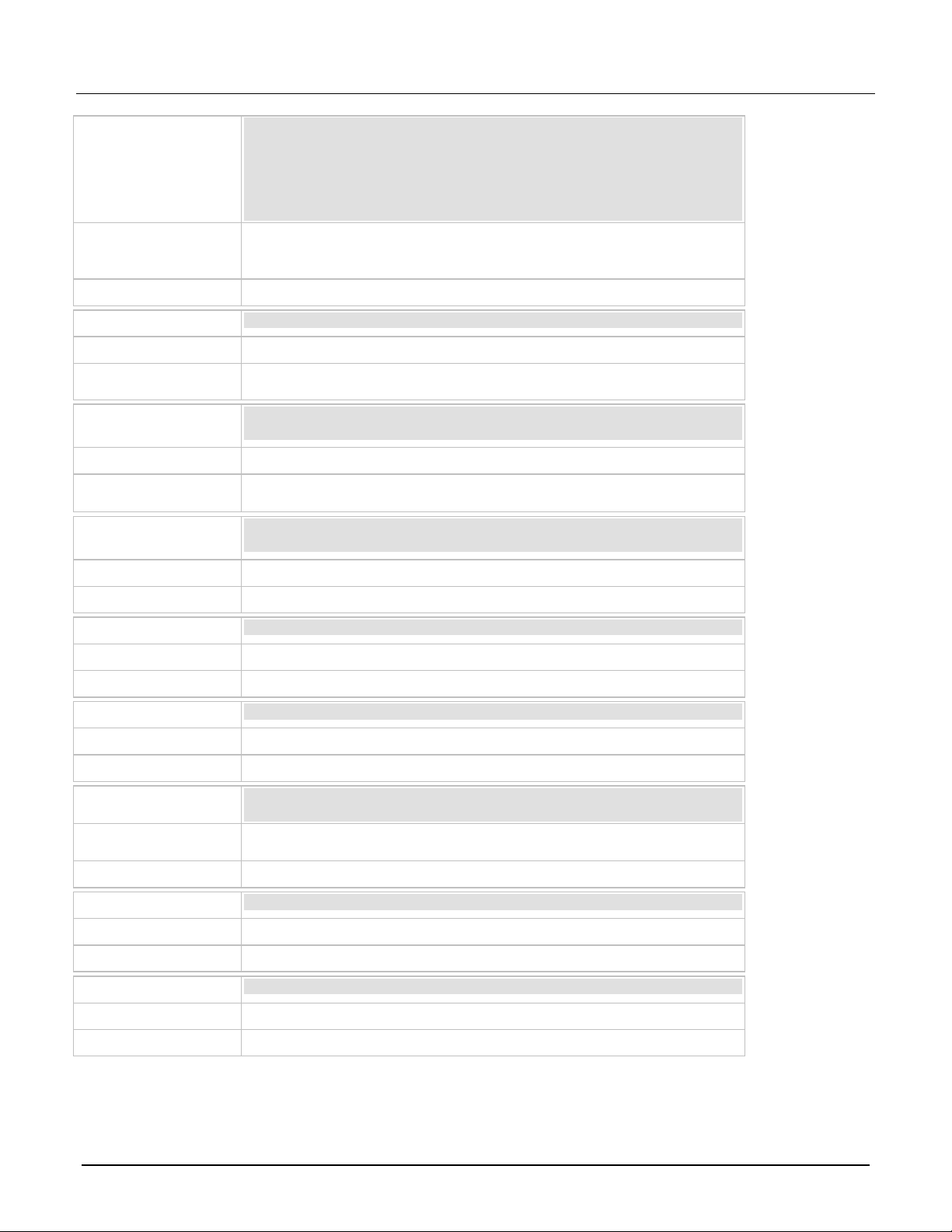
Local
Instrument is controlled from the front panel.
GPIB
Instrument is communicating through a GPIB interface.
TCPIP
Instrument is communicating through a LAN interface.
VXI-11
Instrum ent is commu nicating using VXI-11.
USBTMC
Instrument is communicating through a USB interface.
Telnet
Instrument is communicating through Telnet.
Figure 3: Status and error indicators
The communications indicator is at the left. The options you may see here are listed in the following table.
Indicator Meaning
The communications indicator displays the type of communications the instrument is using. Select the indicator
to display the present communications settings. Select Change Settings at the bottom of the dialog box to
open the System Communications screen, where you can change the settings.
There is an activity indicator next to the communications indicator. When the instrument is communicating with
a remote interface, the up and down arrows flash.
If a service request has been generated, SRQ is displayed to the right of the up and down arrows. You can
instruct the instrument to generate a service request (SRQ) when one or more errors or conditions occur. When
this indicator is on, a service request has been generated. This indicator stays on until the serial poll byte is
read or all the conditions that caused SRQ are cleared.
The measurement mode indicator is on the right. This indicator shows the active measurement method. Select
the indicator to open a menu. Select one of the buttons on the menu to change the measurement method or
initiate or abort the trigger m odel. You can select the foll o wing opt ions :
Continuous Measurement: The instrument is taking measurements continuously. CONT is displayed
when this option is selected.
Manual Trigger Mode: Press the front-panel TRIGGER key to initiate the current trigger model. MAN is
displayed when this option is selected.
The system event indicator is on the far right side of the instrument status indicator bar. This indicator changes
based on the type of event that occurred.
Press the indicator to open a message screen with a brief description of the error, warning, or event. Press the
Event Log button to see the System Events screen, which contains more detailed descriptions of the events
and options for controlling the types of error events that are displayed on the front panel.
4 077162100 / September 2019
Page 5

Model 2461 in a Series 2400 Application Emulation and Migration Guide
An empty triangle means that no new events were logged in the event log since the last time you viewed
A blue circle means that an informational event message was logged. The message is for information
A yellow triangle means that a warning event message was logged. This message indicates that a
The following table describes the different event indicators and what they mean.
Icon Description
the event log.
only. This indicates status changes or information that may be helpful. If the Log Command option is on,
it also includes commands.
change occurred that could affect operat ion.
A red triangle means that an error event message was logged. This may indicate that a command was
sent incorrectly.
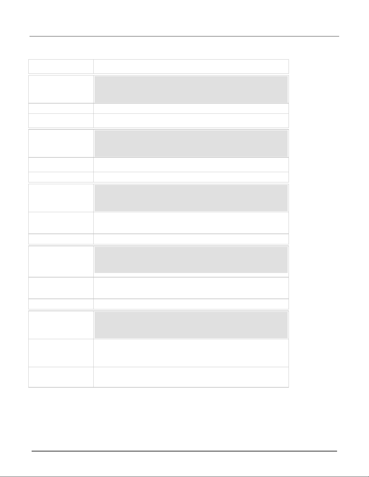
Event messages
During operation and programming, front-panel messages may be displayed. Messages are information,
warning, or error notifications. For information on event messages, refer to "Using the event log" in the Model
®
2461 1 kW Pulse Mode Interactive SourceMeter
Instrument Reference Manual.
Figure 4: Example front-panel error message
Menus when a Series 2400 command set is selected
When a Series 2400 SCPI command set is selected, the only menus available from the front panel are the
QuickSet menu and the System Settings menu. The QuickSet menu is only available through the QUICKSET
key and has limited options.
077162100 / September 2019 5
Page 6

Model 2461 in a Series 2400 Application Emulation and Migration Guide
QuickSet menu when a Series 2400 command set is selected
When a Series 2400 command set is selected, the QuickSet menu is only available through the QUICKSET key
and has limited options. You can set the following options:
Function: Predefined setups for the measurement and source functions
Use the Performance slider to adjust for performance (resolution versus speed)
The Function option allows you to select the same options that you can select by pressing the FUNCTION key.
To select one of the functions, press the function on the touchscreen. You can also select a function by turning
the navigation control to highlight a function, and then pressing the control to select the function.
The Performance slider allows you to adjust the speed and resolution of the instrument based on where you
position the slider. As you increase speed, you lower the amount of resolution. As you increase resolution, you
decrease the reading speed. The settings the performance slider adjusts include autozero, autodelay and filter
settings, display digits, NPLC, and source readback. These settings take effect the next time the output is
turned on and measurements are made.
System menu when a Series 2400 command set is selected
The System menu is available when a Series 2400 command set is selected. The options are the same as the
®
options when the other command sets are selected, except that the TSP-Link
options in the Communication
menu is not available.
Figure 5: Main menu when a Series 2400 SCPI command set is selected
6 077162100 / September 2019
Page 7

Model 2461 in a Series 2400 Application Emulation and Migration Guide
Series 2400 to 2461 command differences
You can use existing code from a Series 2400 application with a 2461; many of the commands are the same.
However, there are some significant differences, including the following exceptions:
Because the 2461 does not have an RS-232 communication port, any commands related to RS-232
communications are accepted and ignored
Because there is no contact check functionality when using a Series 2400 command set, any commands
related to contact-check functionality are accepted and ignored
Because of the change to the display, the DISPlay commands will act differently
Many of the commands in the CALCulate2 subsystem are no longer supported or operate differently
You cannot use the :ABORt command to abort a query that is waiting for a trigger
Details about these differences and other commands that operate differently are described in the following
sections.
If a command is not listed in this section, you can use the command in the same way that you did for the
previous Series 2400 products. The descriptions of the commands are provided in the Series 2400
SourceMeter User's Manual, (part number 2400S-900-01). You can download this manual from
tek.com/keithley
.
Commands that are sup por ted but ope ra te diff er ently
The command :DISPlay:CNDisplay is supported in the command sets of the Series 2400 instruments, but
will return the display to the home screen.
The commands :OUTPut:ENABle[:STATe] and :OUTPut:ENABle:TRIPped? are supported in the Series
2400 SCPI command sets, but they affect the 2461 rear panel INTERLOCK connection instead of the DIGITAL
I/O connection.
If you used :CALCulate2:LIMit<x>:PASS:SOURce2 and :CALCulate2:LIMit<x>:PASS:SOURce2? in
earlier code, replace them with :CALCulate2:LIMit<x>:LOWer:SOURce2 and
:CALCulate2:LIMit<x>:LOWer:SOURce2?
Commands that are not supported in the 2461
The 2461 introduced features and hardware changes that made some earlier commands obsolete. These
commands are documented in this section.
077162100 / September 2019 7
Page 8

Model 2461 in a Series 2400 Application Emulation and Migration Guide
RS-232 commands
The 2461 no longer supports the RS-232 interface, so commands related to RS-232 operation are not
supported even when you are using a Series 2400 SCPI command set.
If you have existing code that sets RS-232 parameters, the commands will be accepted and ignored.
Commands that are related to the RS-232 interface that are no longer available are listed below.
:SYSTem:LOCal
:SYSTem:RWLock
Contact check commands
The 2461 does not support contact check, so commands related to this feature are not supported even when
you are using a Series 2400 command set.
If you have existing code that sets contact check parameters, the commands are accepted and ignored or are
accepted and return a default value.
The Series 2400 SCPI commands related to this feature and the 2461 response to them are listed below.
Commands that are accepted and ignored
:CALCulate2:LIMit4:FAIL?
:CALCulate2:LIMit4:SOURce2
:CALCulate2:LIMit4:SOURce2?
:CALCulate2:LIMit4:STATe
:CALCulate2:LIMit4:STATe?
:SYSTem:CCHeck
:SYSTEM:CCHeck?
:SYSTem:CCHEck:RESistance
:SYSTem:CCHeck:RESistance?
:TRIGger:SEQuence2:TOUT
:TRIGger:SEQuence2:TOUT?
:TRIGger:SEQuence2:SOURce
:TRIGger:SEQuence2:SOURce?
Commands that are accepted and return a default value
*OPT? (0 is returned)
8 077162100 / September 2019
Page 9

Model 2461 in a Series 2400 Application Emulation and Migration Guide
Display commands
The 2461 display is significantly different than the display of earlier models, so some commands related to the
display no longer apply when you are using the Ser ies 2400 SCPI com mand set.
If you have existing code that sets display parameters, the commands will either be accepted and return
defaults, or be accepted and ignored.
The Series 2400 commands related to this display that are no longer available are listed below:
:DISPlay:ENABle
:DISPlay:ENABle?
:DISPlay:WINDow[1]:ATTRibutes?
:DISPlay:WINDow[1]:DATA?
:DISPlay:WINDow2:ATTRibutes?
:DISPlay:WINDow2:DATA?
Other commands
Some additional commands are no longer supported when you are using the Series 2400 SCPI command set.
The 2461 accepts the following command but ignores it:
:SYSTem:MEMory:INITialize
The 2461 accepts the following command but returns a default of 0:
*TST?
The 2461 accepts the following command but returns the last key that was remapped to the ENTER or EXIT
keys:
:SYSTem:KEY
Commands that were added to the SCPI command sets
To replace some features that are needed to use the 2461 in a Series 2400 application, the following
commands were added.
:SYSTem:GPIB:ADDRess: Assigns a GPIB address through a remote interface.
:SYSTem:TLINk: Sets the digital I/O port to digital I/O or Trigger Link. See below for detail.
077162100 / September 2019 9
Page 10

Model 2461 in a Series 2400 Application Emulation and Migration Guide
The :SYSTem:GPIB:ADDRess: usage format is:
:SYSTem:GPIB:ADDRess <n>
Where <n> is the GPIB address of the instrument (1 to 30), or
:SYSTem:GPIB:ADDRess?
Which is used to query the address of the instrument.
The address can be set to any address value from 1 to 30. However, the address must be unique in the
system. It cannot conflict with an address that is assigned to another instrument or to the GPIB controller. A
new GPIB address takes effect when the command to change it is processed. If there are response messages
in the output queue when this command is processed, they must be read at the new address.
If command messages are being queued (sent before this command has executed), the new settings may take
effect in the middle of a subsequent command message, so care should be exercised when setting this
attribute from the GPIB interface.
You should allow ample time for the command to be processed before attempting to communicate with the
instrument again. After sending this command, make sure to use the new address to communicate with the
instrument.
*RST does not affect the GPIB address.
The :SYSTem:TLINk usage format is:
:SYSTem:TLINk <n>
Where <n> is:
0: Digital I/O connections. The DIGITAL I/O port on the rear panel of the instrument is set for digital I/O
connections.
1: Trigger Link. The DIGITAL I/O port on the rear panel of the instrument is set for Trigger Link (TLINK)
connections.
10 077162100 / September 2019
Page 11

Model 2461 in a Series 2400 Application Emulation and Migration Guide
This command is stored in nonvolatile memory (the setting is retained through a power cycle). It is not saved as
part of the user-saved setup (*SAV and *RCL).
When the port is set for digital I/O, the following signals are available on the digital I/O connector:
Pin 1: Out 1
Pin 2: Out 2
Pin 3: Out 3
Pin 4: Out 4 (end-of-test (EOT) or BUSY)
Pin 6: Input (start-of-test (SOT))
When the port is set for Trigger Link, the following signals are available on the digital I/O connector:
Pin 1: Trigger Link 1
Pin 2: Trigger Link 2
Pin 3: Trigger Link 3
Pin 4: Trigger Link 4
Pin 6: Input (start-of-test (SOT))
You can use the Series 2400 commands that support digital I/O and Trigger Link with these settings. For
example, you can use the SOURce2:TTL command to set the I/O port bit pattern for the digital I/O state. The
:ARM[:SEQuence[1]][LAYer[1]]:SOURce TLINk command can be used when the state is TLINk.
Using Trigger Link or Digital I/O
The 2461 can support digital I/O or Trigger Link (TLINK) applications when a SCPI command set of the
emulated instrument is selected. However, it cannot support both digital I/O and TLINK connections at the
same time.
If you are using a 2461 in an application that used only the Series 2400 digital I/O, send the command:
:SYSTem:TLINk 0
This sets the digital I/O port lines of the 2461 to operate the lines with the same pinouts as those on the Series
2400.
If you are using a 2461 in an application that used only the Series 2400 Trigger Link (TLINK) connector, send
the command:
:SYSTem:TLINk 1
This sets the digital I/O port lines to operate with the same connections as a Series 2400 TLINK connection.
You can use the Model 2450-TLINK DB-9 to Trigger Link Connector Adapter to connect to the digital I/O
connector.
077162100 / September 2019 11
Page 12

Model 2461 in a Series 2400 Application Emulation and Migration Guide
If the connection to the digital I/O connector is always the same (either digital I/O or TLINK), you do not need to
send the :SYSTem:TLINk command again. It is saved through power cycles.
If you are using the 2461 in a Series 2400 application that used both digital I/O and TLINK, you need to make
changes to your application to accommodate the differences. One way to do this is to use the *SAV and *RCL
commands to save and recall the settings for each type of connection. Note that the :SYSTem:TLINk
command is not saved with the user-saved setup, so you must send that command for each change to digital
I/O or TLINK.
For example, you might save the settings as follows.
Set the digital I/O port as a Series 2400 digital I/O:
:SYSTem:TLINk 0
Make other settings for the digital I/O application.
Save the settings to memory location 1:
*SAV 1
Set the digital I/O port as a Series 2400 TLINK:
:SYSTem:TLINk 1
Make other settings for the TLINK application.
Save the settings to memory location 2:
*SAV 2
To change between the applications, attach the appropriate cable (digital I/O or TLINK) and send the :SYSTem
TLINk command followed by the *RCL command.
For example, to restore the settings for the digital I/O application, send the command:
:SYSTem:TLINk 0
*RCL 1
To restore the settings for the TLINK application, send the command:
:SYSTem:TLINk 1
*RCL 2
For more detail on the :SYSTem:TLINk command, see Commands that were added to the SCPI command
sets (on page 9).
12 077162100 / September 2019
Page 13

Model 2461 in a Series 2400 Application Emulation and Migration Guide
Converting Series 2400 code to 2461 code
This section provides information about converting existing Series 2400 SCPI code to 2461 SCPI code.
You must use the SCPI command set to use the new commands. See "Determining the command set you will
®
use" in the Model 2461 1 kW Pulse Mode Interactive SourceMeter
number 2461-901-01), which you can download from tek.com/keithley
This section also lists the SCPI commands that were available with the Series 2400 instruments. If there is an
equivalent command in the 2461, a cross-reference to that command is provided. Differences between the
commands are noted. If no differences are noted, the command should operate the same on the 2461 as it did
on the Series 2400.
"Series 2400" in this document refers to the Model 2420, 2425, 2430, and 2440 instruments.
Instrument Reference Manual, (part
.
Significant differences
This topic describes some of the more significant differences between the Series 2400 SCPI commands and
the 2461 commands.
Acquiring readings
The commands that you use to acquire readings have changed in the 2461.
When you make measurements, the 2461 allows you to select the buffer in which to store data and the buffer
elements that should be stored. This change affects the FETCh?, READ?, and MEASure? commands.
In the 2461, the :FORMat:ELEMents[:SENSe[1]] command is no longer available. Instead, you specify the
format elements as part of the READ?, FETCh?, MEASure?, and TRACe:DATA? commands. The format
elements are specified with each use of the command instead of using a global setting for all commands. The
elements can be unique for each command and can be unique each time the command is processed.
In the 2461, the READ? command does not initiate a trigger when it makes a measurement. It also makes only
one measurement at a time. The data is automatically stored in a buffer (defbuffer1 if the buffer is not
specified in the command).
In the 2461, use the TRACe:DATA? command to read a specified amount of data from the buffer instead of all
data. You can also define which data to return, such as the date, time, and units of measure.
077162100 / September 2019 13
Page 14

Model 2461 in a Series 2400 Application Emulation and Migration Guide
*RST
*RST
SOUR:FUNC VOLT
SOUR:FUNC VOLT
SOUR:DEL 0.1
SOUR:VOLT 5
SOUR:VOLT 5
SOUR:VOLT:ILIM 0.01
SENS:FUNC "CURR"
SENS:FUNC "CURR"
SENS:CURR:RANG:AUTO ON
SENS:CURR:RANG:AUTO ON
SENS:CURR:PROT 0.01
TRIG:LOAD "SimpleLoop", 10, 0.1
:FORM:ELEM VOLT, CURR, TIME
OUTP ON
:TRIG:COUNT 10
INIT
:SYST:TIME:RES:AUTO ON
*WAI
:OUTP ON
TRAC:DATA? 1, 10, "defbuffer1", SOUR, READ, REL
READ?
OUTP OFF
OUTP OFF
The :INITiate command starts the trigger model. To trigger measurements when you are not using the
trigger model, use the :TRACe:TRIGger command.
The command for the number of readings is also different. In the 2461, use the Simple Loop Trigger Template
command TRIG:LOAD "SimpleLoop".
An example of a data acquisition done for the Model 2425 compared with one done for the 2461 is shown in the
following table. In these exam ples , the SourceM eter
current readings with autorange ON. The instruments return the source value, current measurements, and
relative timestamps.
2425 2461
®
instruments are programmed to output 5 V and make 10
Making resistance measurements
The method for selecting manual or auto ohms and for making resistance measurements is different in the
2461 than it is in the Series 2400 instruments. For more information, see "Making resistance measurements" in
®
the "General operation" section of the Model 2461 1 kW Pulse Mode Interactive SourceMeter
Reference Manual, which you can do wnlo ad from tek.com/keithley
.
Instrument
14 077162100 / September 2019
Page 15

Model 2461 in a Series 2400 Application Emulation and Migration Guide
:CURR:PROT
:SOUR:VOLT:ILIM
:CURR:PROT?
:SOUR:VOLT:ILIM?
:CURR:PROT:TRIP?
:SOUR:VOLT:ILIM:TRIP?
:VOLT:PROT
:SOUR:CURR:VLIM
:VOLT:PROT?
:SOUR:CURR:VLIM?
:VOLT:PROT:TRIP?
:SOUR:CURR:VLIM:TRIP?
Compliance is now limit
The Series 2400 instruments used the term "compliance" to specify the maximum current or voltage that the
instrument can source. The 2461 uses the term "source limit" to specify the maximum current or voltage that
the instrument can source. For more information, see "Source limits" in the "General operation" section of the
®
Model 2461 1 kW Pulse Mode Interactive SourceMeter
This change affects the commands that you use to set and verify the source limit. The following table shows the
Series 2400 SCPI command from the command set of the emulated instruments and the 2461 command that
replaces it.
Series 2400 2461
Instrument Reference Manual.
For additional detail, see the following command descriptions in the Model 2461 1 kW Pulse Mode Interactive
®
SourceMeter
Instrument Reference Manual, which you can download from tek.com/keithley.
:SOURce[1]:<function>:<x>LIMit[:LEVel]
:SOURce[1]:<function>:<x>LIMit[:LEVel]:TRIPped?
Event log
The 2461 provides expanded system event logging. Events include errors, warnings, and information
messages. You can also log commands through the front panel.
In the 2461, event tracking is done as events are received by the instrument, not when they are executed.
®
Refer to "Using the event log" in the Model 2461 1 kW Pulse Mode Interactive SourceMeter
Instrument
Reference Manual. for information.
Buffers
The Series 2400 has two buffers. The 2461 has two default buffers and you can define additional buffers. Only
one buffer is active.
For information about using buffers, see "Reading buffers" in the Model 2461 1 kW Pulse Mode Interactive
®
SourceMeter
Instrument Reference Manual, which you can download from tek.com/keithley.
077162100 / September 2019 15
Page 16

Model 2461 in a Series 2400 Application Emulation and Migration Guide
*RST
*RST
SOUR:FUNC VOLT
SOUR:FUNC VOLT
SOUR:VOLT:MODE SWEEP
SOUR:SWE:VOLT:LIN 0, 0.55, 56, 0.1
SOUR:VOLT:START 0
SOUR:VOLT:STOP 0.55
SOUR:VOLT:STEP 0.01
TRIG:COUNT 56
SOUR:DEL 0.1
*RST
*RST
SOUR:FUNC VOLT
SOUR:FUNC VOLT
SOUR:DEL 0.2
SOUR:VOLT:ILIM 1
SOUR:VOLT:MODE LIST
SOUR:LIST:VOLT 10, 1, 4, 3, 4, 2
SOUR:LIST:VOLT 10, 1, 4, 3, 4, 2
SOUR:SWE:VOLT:LIST 1, 0.2
SENS:FUNC "CURR"
SENS:FUNC "CURR"
SENS:CURR:RANG:AUTO ON
SENS:CURR:RANG:AUTO ON
SENS:CURR:PROT 0.01
INIT
:FORM:ELEM VOLT, CURR
*WAI
TRIG:COUNT 6
TRAC:DATA? 1, 6, "defbuffer1", SOUR, READ
:SYST:TIME:RES:AUTO ON
OUTP OFF
OUTP ON
READ?
OUTP OFF
Sweeps
In the 2461, sweep commands include all the settings for the sweep in the sweep commands. An example of a
sweep set up for a Series 2400 instrument compared to a sweep set up for a 2461 is shown in the table below.
These examples configure the instrument to output a voltage sweep from 0 V to 0.55 V in 56 steps with a
100 ms delay.
Series 2400 2461
In the 2461, when you create a sweep, a trigger model for that sweep is automatically created. You can view
and create sweeps and the related trigger models using the front panel, but not when you use a Series 2400
SCPI command set.
The list sweep for a Series 2400 compared to the 2461 is similar. An example of a list sweep for the
Series 2400 compared with one done for the 2461 is shown in the following table. Note that for the 2461, the
trigger count and voltage source mode do not have to be specified in separate commands, and the output is
turned on and off automatically as part of the sweep.
Series 2400 2461
For additional information about how to set up sweeps, see "Sweep operation" in the Model 2461 1 kW Pulse
®
Mode Interactive SourceMeter
Instrument Reference Manual, which you can download from tek.com/keithley.
16 077162100 / September 2019
Page 17

Model 2461 in a Series 2400 Application Emulation and Migration Guide
Trigger model
The trigger model has changed significantly from the Series 2400 instruments to the 2461.
The ARM subsystem commands are no longer available. The commands for the trigger model are now in the
TRIGger subsystem.
The following templates are not available when you use a Series 2400 SCPI command set with the
2461.
The 2461 includes trigger model templates for common applications. You can use these templates without
changing them, or you can modify them to meet the needs of your application.
The trigger model templates include:
Empty: Clears the present trigger model.
ConfigList: Creates a trigger model that loads a source and measure configuration list. The lists are
iterated until every index in the configuration list with fewer indexes has been loaded. For example, if the
measure list has seven indexes and the source configuration list has 10, it will iterate through seven
indexes of the source list and all of the measure list. However, if the source list has three indexes and the
measure list has five, it will iterate through three indexes of measure list and all of the indexes in the
source list. At each index when the output is turned on, a measurement is made and the output is turned
off.
LogicTrigger: Creates a trigger model that waits on an input line, delays, makes a measurement, and
sends out a trigger on the output line a specified number of times.
SimpleLoop: Creates a trigger model that makes a specified number of readings. A count parameter
defines the number of readings.
DurationLoop: Creates a trigger model that makes continuous measurements for a specified amount of
time. When you start this trigger model, the output is turned on.
LoopUntilEvent: Creates a trigger model that makes continuous measurements until a specified event
occurs.
GradeBinning: Creates a trigger model that successively measures components and compares their
readings to high or low limits to grade components.
SortBinning: Creates a trigger model that successively measures components and compares their
readings to high or low limits to sort components.
For detail about the 2461 trigger model, see "Trigger model" in the Model 2461 1 kW Pulse Mode Interactive
®
SourceMeter
Instrument Reference Manual, which you can download from tek.com/keithley.
077162100 / September 2019 17
Page 18

Model 2461 in a Series 2400 Application Emulation and Migration Guide
:CALCulate[1]:DATA?
Not supported
Use the buffer to get user math data; see "TRACe subsystem" in the
Manual.
:CALCulate[1]:DATA:LATest?
Not supported
Use the buffer to get user math data; see "TRACe subsystem" in the
Manual.
Pulsing (Model 2430 feature)
If you are bringing code from a Model 2430 to a 2461, the pulsing features and commands have changed
significantly. Refer to "Pulse operation" in the Model 2461 1 kW Pulse Mode Interactive SourceMeter
Instrument Reference Manual for more information.
For specific commands, refer to the following command descriptions in the Model 2461 1 kW Pulse Mode
®
Interactive SourceMeter
:SOURce[1]:PULSe:<function>:<x>LIMit[:LEVel]
:SOURce[1]:PULSe:<function>[:LEVel][:IMMediate][:AMPLitude]
:SOURce[1]:PULSe:LIST:<function>
:SOURce[1]:PULSe:LIST:<function>:APPend
:SOURce[1]:PULSe:LIST:<function>:POINts?
:SOURce[1]:PULSe:SWEep:<function>:LINear
:SOURce[1]:PULSe:SWEep:<function>:LINear:STEP
:SOURce[1]:PULSe:SWEep:<function>:LIST
:SOURce[1]:PULSe:SWEep:<function>:LOG
:SOURce[1]:PULSe:TRain:<function>
Instrument Reference Manu a l, which you can download from tek.com/keithley.
®
Series 2400 to 2461 SCPI command cross-reference
This section provides information to help you convert existing Series 2400 code to 2461 SCPI code.
You must use the SCPI command set to use the new commands. See the Model 2461 1 kW Pulse Mode
®
Interactive SourceMeter
This section lists the SCPI commands that were available with the Series 2400 instruments, cross-referenced
to the equivalent commands in the 2461 where available. Differences between the commands are noted. If no
differences are noted, the command should operate the same way on the 2461 as it did on the Series 2400.
CALCulate[1] subsystem
Series 2400
2461
Notes
Series 2400
2461
Notes
Instrument Reference Manu a l, which you can downl oad from tek.com/keithley.
Model
Model
2461 1 kW Pulse Mode Interactive SourceMeter
2461 1 kW Pulse Mode Interactive SourceMeter
®
Instrument Reference
®
Instrument Reference
18 077162100 / September 2019
Page 19

Model 2461 in a Series 2400 Application Emulation and Migration Guide
:CALCulate[1]:MATH[:EXPression]:CATalog?
Not supported
:CALCulate[1]:MATH[:EXPRession][:DEFine]
2461
Not supported
:CALCulate[1]:MATH[:EXPRession]:DELete:ALL
Not supported
:CALCulate[1]:MATH[:EXPRession]:DELete[:SELected]
Not supported
:CALCulate[1]:MATH[:EXPression]:NAME
:CALCulate[1]:MATH[:EXPression]:NAME?
POWER:[SENSe[1]]:<function>:UNIT, where <function> is VOLTage
:CALCulate[1]:STATe
:CALCulate[1]:STATe?
, where
is
If you send :CALCulate[1]:STATe, it sets the math state for all functions. If
:CALCulate[1]:STATe?
:CALCulate[1]:MATH:UNITs
:CALCulate[1]:MATH:UNITs?
Not supported
:CALCulate2:CLIMits:BCONtrol
:CALCulate2:CLIMits:BCONtrol?
Not supported
:CALCulate2:CLIMits:CLEar:AUTO
:CALCulate2:CLIMits:CLEar:AUTO?
Not supported
Series 2400
2461
Notes
Series 2400
Notes
Series 2400
2461
Notes
Series 2400
2461
Notes
Series 2400
2461
or CURRent and the setting is WATT.
OFFCOMPOHM, VOLTCOEFF, and VARALPHA are not available.
Notes
Series 2400
2461
:CALCulate[1]:<function>:MATH:STATe
VOLTage[:DC], CURRent[:DC], or RESistance.
:CALCulate[1]:<function>:MATH:STATe?
Notes
you send
Series 2400
2461
Notes
CALCulate2 subsystem
Series 2400
2461
<function>
, a header error event occurs.
Notes
Series 2400
2461
Notes
077162100 / September 2019 19
Page 20

Model 2461 in a Series 2400 Application Emulation and Migration Guide
:CALCulate2:CLIMits:CLEar[:IMMediate]
Not supported
:CALCulate2:CLIMits:FAIL:SMLocation
:CALCulate2:CLIMits:FAIL:SMLocation?
Not supported
:CALCulate2:CLIMits:FAIL:SOURce2
:CALCulate2:CLIMits:FAIL:SOURce2?
Not supported
:CALCulate2:CLIMits:MODE
:CALCulate2:CLIMits:MODE?
Not supported
:CALCulate2:CLIMits:PASS:SMLocation
:CALCulate2:CLIMits:PASS:SMLocation?
Not supported
:CALCulate2:CLIMits:PASS:SOURce2
:CALCulate2:CLIMits:PASS:SOURce2?
Not supported
:CALCulate2:DATA?
Not supported
:CALCulate2:DATA:LATest?
Not supported
:CALCulate2:FEED
:CALCulate2:FEED?
Not supported
:CALCulate2:LIMit[1]:COMPliance:FAIL
:CALCulate2:LIMit[1]:COMPliance:FAIL?
Not supported
Series 2400
2461
Notes
Series 2400
2461
Notes
Series 2400
2461
Notes
Series 2400
2461
Notes
Series 2400
2461
Notes
Series 2400
2461
Notes
Series 2400
2461
Notes
Series 2400
2461
Notes
Series 2400
2461
Notes
Series 2400
2461
Notes
20 077162100 / September 2019
Page 21
Model 2461 in a Series 2400 Application Emulation and Migration Guide
:CALCulate2:LIMit[1]:COMPliance:SOURce2
:CALCulate2:LIMit[1]:COMPliance:SOURce2?
Not supported
:CALCulate2:LIMit[1]:FAIL?
Not supported
:CALCulate2:LIMit[1]:STATe
:CALCulate2:LIMit[1]:STATe?
Not supported
To disable source limits, set the limit value to the maximum allowed by the
instrument.
:CALCulate2:LIMit<x>:FAIL?
:CALCulate2:<function>:LIMit<Y>:FAIL?, where <function> is
VOLTage[:DC], CURRent[:DC]
RESistance
:CALCulate2:LIMit<x>:LOWer[:DATA]
:CALCulate2:LIMit<x>:LOWer[:DATA]?
:CALCulate2:<function>:LIMIT<Y>:LOWer[:DATA], where
<function>
VOLTage[:DC], CURRent[:DC]
RESistance
Note that this is only available for two limits in the 2461.
:CALCulate2:LIMit<x>:LOWer:SOURce2
:CALCulate2:LIMit<x>:LOWer:SOURce2?
Not supported
:CALCulate2:LIMit<x>:PASS:SOURce2
Not supported
:CALCulate2:LIMit<x>:STATe
:CALCulate2:LIMit<x>:STATe?
:CALCulate2:<function>:LIMit<Y>:STATe, where <function> is
VOLTage[:DC], CURRent[:DC], or RESistance and <Y> is 1 or 2.
Note that this is only available for two limits in the 2461.
instrument.
:CALCulate2:LIMit<x>:UPPer[:DATA]
:CALCulate2:LIMit<x>:UPPer[:DATA]?
:CALCulate2:<function>:LIMit<Y>:UPPer[:DATA], where
1
Note that this is only available for two limits in the 2461.
Series 2400
2461
Notes
Series 2400
2461
Notes
Series 2400
2461
Notes
Series 2400
2461
Notes
Series 2400
2461
Notes
Series 2400
2461
Notes
Series 2400
2461
Notes
Series 2400
2461
, or
is
:CALCulate2:LIMit<x>:PASS:SOURce2?
.
, or
.
Notes
To disable source limits, set the limit value to the maximum allowed by the
Series 2400
2461
<function> is VOLTage[:DC], CURRent[:DC], or RESistance and <Y> is
or 2.
Notes
077162100 / September 2019 21
Page 22

Model 2461 in a Series 2400 Application Emulation and Migration Guide
:CALCulate2:LIMit<x>:UPPer:SOURce2
:CALCulate2:LIMit<x>:UPPer:SOURce2?
:CALCulate2:NULL:ACQuire
[:SENSe[1]]:<function>:RELative:ACQuire, where <function> is
VOLTage[:DC], CURRent[:DC]
RESistance
:CALCulate2:NULL:OFFSet
:CALCulate2:NULL:OFFSet?
[:SENSe[1]]:<function>:RELative, where <function> is
[:SENSe[1]]:<function>:RELative?
:CALCulate2:NULL:STATe
:CALCulate2:NULL:STATe?
[:SENSe[1]]:<function>:RELative:STATe, where <function> is
VOLTage[:DC], CURRent[:DC]
RESistance
:CALCulate3:DATA?
Not supported
Use reading buffers; see "TRACe subsystem" in the Model 2461 1 kW Pulse
Mode Interactive SourceMeter® Instrument Reference Manual.
:CALCulate3:FORMat
:CALCulate3:FORMat?
Use reading buffers; see "TRACe subsystem" in the Model 2461 1 kW Pulse
Mode Interactive SourceMeter® Instrument Reference Manual.
:CONFigure
:CONFigure?
Not supported
Series 2400
2461
Notes
Not supported
Series 2400
2461
Notes
Series 2400
2461
VOLTage[:DC], CURRent[:DC], or RESistance.
Notes
Series 2400
2461
Notes
CALCulate3 subsystem
Series 2400
, or
, or
.
.
2461
Notes
Series 2400
2461
Notes
CONFigure
Series 2400
2461
Notes
Not supported
22 077162100 / September 2019
Page 23

Model 2461 in a Series 2400 Application Emulation and Migration Guide
:DISPlay:CNDisplay
:DISPlay:SCReen
:DISPlay:DIGits
:DISPlay:DIGits?
, where
is
,
:DISPlay:<function>:DIGits?
Settings are 3 to 6 instead of 4 to 7.
:DISPlay:ENABle
:DISPlay:ENABle?
:DISPlay:LIGHt:STATe
:DISPlay:LIGHt:STATe?
The Series 2400 uses the :DISPlay:ENABle to stop display updates for
performance reasons . The 2461 does not.
:DISPlay[:WINDow[1]]:ATTRibutes?
Not supported
:DISPlay[:WINDow[1]]:DATA?
:DISPlay:WINDow<n>:TEXT:DATA
:DISPlay:WINDow<n>:TEXT:DATA?
:DISPlay:USER<n>:TEXT[:DATA]
:DISPlay:USER<n>:TEXT[:DATA]?
:DISPlay:WINDow<n>:TEXT:STATe
:DISPlay:WINDow<n>:TEXT:STATe?
:DISPlay:USER<n>:TEXT[:DATA]
:DISPlay:USER<n>:TEXT[:DATA]?
:DISPlay:WINDow2:ATTRibutes?
Not supported
:DISPlay:WINDow2:DATA?
Not supported
DISPlay subsystem
Series 2400
2461
Notes
Series 2400
2461
Notes
Series 2400
2461
Notes
Series 2400
2461
Notes
Series 2400
2461
Notes
Series 2400
2461
Notes
Series 2400
:DISPlay:<function>:DIGits
CURRent[:DC], or RESistance.
Not supported
<function>
VOLTage[:DC]
2461
Notes
Series 2400
2461
Notes
Series 2400
2461
Notes
077162100 / September 2019 23
Page 24

Model 2461 in a Series 2400 Application Emulation and Migration Guide
:FETCh?
:FETCh?
You can choose different buffers and which buffer elements to access from the
buffer for 2461.
:FORMat:BORDer
:FORMat:BORDer?
:FORMat:BORDer
:FORMat:BORDer?
:FORMat[:DATA]
:FORMat[:DATA]?
:FORMat[:DATA]
:FORMat[:DATA]?
:FORMat:ELEMents[:SENSe[1]]
:FORMat:ELEMents[:SENSe[1]]?
Not supported
In the 2461, format elements are specified as part of the READ?, FETCh?,
processed.
:FORMat:ELEMents:CALCulate
:FORMat:ELEMents:CALCulate?
Not supported
:FORMat:SOURce2
:FORMat:SOURce2?
Not supported
:FORMat:SREGister
:FORMat:SREGister?
FETCh?
Series 2400
2461
Notes
FORMat subsystem
Series 2400
2461
Notes
Series 2400
2461
Notes
Series 2400
2461
Notes
Series 2400
2461
Notes
Series 2400
MEASure?, and TRACe:DATA? commands with each use of the command
instead of using a global setting for all commands. The elements may be
unique for each command and are unique each time the command is
2461
Notes
Series 2400
2461
Notes
Not supported
24 077162100 / September 2019
Page 25

Model 2461 in a Series 2400 Application Emulation and Migration Guide
:MEASure:CURRent[:DC]?
:MEASure:VOLTage[:DC]?
:MEASure:<function>?, where <function> is VOLTage[:DC],
CURRent[:DC]
RESistance
You can specify a buffer in the 2461 and which buffer elements to access from
CONFigure, READ?
FETCh?
:OUTPut[1]:ENABle[:STATe]
:OUTPut[1]:ENABle[:STATe]?
Not supported
:OUTPut[1]:ENABle:TRIPped?
Not supported
:OUTPut[1]:INTerlock:TRIPped?
:OUTPut[1]:INTerlock:TRIPped?
:OUTPut[1]:SMODe
:OUTPut[1]:SMODe?
, where
is
:OUTPut[1]:<function>:SMODe?
:OUTPut[1][:STATe]
:OUTPut[1][:STATe]?
:OUTPut[1][:STATe]
:OUTPut[1][:STATe]?
MEASure:<function>?
Series 2400
:MEASure:RESistance?
2461
Notes
the buffer when you specify the command. In the 2461, this command changes
the measurement function to the function in the command if it is not already
active, makes readings, and stores them in a reading buffer, which you can
specify. When it changes to that function, it recalls the settings as they were the
last time that function was active. It does not go to factory default settings for
the function, as in the Series 2400 instruments. Also, in the 2461, this
command does not map to
OUTPut subsystem
Series 2400
2461
Notes
Series 2400
2461
Notes
Series 2400
2461
, or
.
, and
.
Notes
Series 2400
2461
:OUTPut[1]:<function>:SMODe
or CURRent[:DC].
Notes
Series 2400
2461
Notes
077162100 / September 2019 25
<function>
VOLTage[:DC]
Page 26
Model 2461 in a Series 2400 Application Emulation and Migration Guide
:READ?
:READ?
The 2461 allows you to choose different buffers and which buffer elements to
access from the buffers when you send the command.
:ROUTe:TERMinals
:ROUTe:TERMinals
:ROUTe:TERMinals?
[:SENSe[1]]:AVERage:COUNt
[:SENSe[1]]:AVERage:COUNt?
[:SENSe[1]]:<function>:AVERage:COUNt, where <function> is
VOLTage[:DC], CURRent[:DC]
RESistance
This is now set for each measurement function.
[:SENSe[1]]:AVERage[:STATe]
[:SENSe[1]]:AVERage[:STATe]?
[:SENse[1]]:<function>:AVERage[:STATe], where <function> is
VOLTage[:DC], CURRent[:DC]
RESistance
This is now set for each measurement function.
[:SENSe[1]]:AVERage:TCONtrol
, where
is
VOLTage[:DC], CURRent[:DC]
RESistance
[:SENSe[1]]:CURRent[:DC]:NPLCycles
[:SENSe[1]]:VOLTage[:DC]:NPLCycles?
where
is
[:SENSe[1]]:<function>:NPLCycles?
If you send [:SENSe[1]]:NPLCycles, it sets NPLCs for all functions.
[:SENSe[1]]:CURRent[:DC]:PROTection[:LEVel]
[:SENSe[1]]:CURRent[:DC]:PROTection[:LEVel]?
:SOURce[1]:<function>:<x>LIMit[:LEVel], where <function> is
VOLTage[:DC], CURRent[:DC]
RESistance
READ?
Series 2400
2461
Notes
ROUTe subsystem
Series 2400
:ROUTe:TERMinals?
2461
Notes
SENSe subsystem
Series 2400
2461
Notes
Series 2400
2461 command
Notes
Series 2400
2461
Notes
Series 2400
, or
, or
[:SENSe[1]]:AVERage:TCONtrol?
[:SENSe[1]]:<function>:AVERage:TCONtrol
, or
This is now set for each measurement function.
[:SENSe[1]]:CURRent[:DC]:NPLCycles?
[:SENSe[1]]:RESistance:NPLCycles
[:SENSe[1]]:RESistance:NPLCycles?
[:SENSe[1]]:VOLTage[:DC]:NPLCycles
.
.
<function>
.
2461
[:SENSe[1]]:<function>:NPLCycles,
VOLTage[:DC], CURRent[:DC], or RESistance.
Notes
Series 2400
2461
, or
Notes
26 077162100 / September 2019
<function>
.
Page 27

Model 2461 in a Series 2400 Application Emulation and Migration Guide
[:SENSe[1]]:CURRent[:DC]:PROTection:RSYNchronize
[:SENSe[1]]:VOLTage[:DC]:PROTection:RSYNchronize?
Not supported
Range synchronization is always turned on in 2461.
[:SENSe[1]]:CURRent[:DC]:PROTection:TRIPped?
:SOURce[1]:<function>:<x>LIMit[:LEVel]:TRIPped?, where
<function>
VOLTAGE [:DC]
CURRent [:DC]
<x>
[:SENSe[1]]:CURRent[:DC]:RANGe:AUTO
[:SENSe[1]]:VOLTage[:DC]:RANGe:AUTO?
, where
is
[:SENSe[1]]:<function>:RANGe:AUTO?
[:SENSe[1]]:CURRent[:DC]:RANGe:AUTO:LLIMit
[:SENSe[1]]:VOLTage[:DC]:RANGe:AUTO:LLIMit?
[:SENSe[1]]:<function>:RANGe:AUTO:LLIMit, where <function> is
[:SENSe[1]]:<function>:RANGe:AUTO:LLIMit?
[:SENSe[1]]:CURRent[:DC]:RANGe:AUTO:ULIMit?
[:SENSe[1]]:VOLTage[:DC]:RANGe:AUTO:ULIMit?
, where
is
VOLTage[:DC], CURRent[:DC]
RESistance
Upper limit is not available for voltage or current for the 2461. For voltage and
current, you can query the upper limit for voltage, but not set i t .
[:SENSe[1]]:CURRent[:DC]:RANGe:HOLDoff
[:SENSe[1]]:CURRent[:DC]:RANGe:HOLDoff?
Not supported
[:SENSe[1]]:CURRent[:DC]:RANGe:HOLDoff:DELay
[:SENSe[1]]:CURRent[:DC]:RANGe:HOLDoff:DELay?
Not supported
Series 2400
2461
Notes
Series 2400
[:SENSe[1]]:CURRent[:DC]:PROTection:RSYNchronize?
[:SENSe[1]]:VOLTage[:DC]:PROTection:RSYNchronize
2461
Notes
Series 2400
2461
Notes
Series 2400
2461
Notes
Series 2400
is
or
and
[:SENSe[1]]:CURRent[:DC]:RANGe:AUTO?
[:SENSe[1]]:RESistance:RANGe:AUTO
[:SENSe[1]]:RESistance:RANGe:AUTO?
[:SENSe[1]]:VOLTage[:DC]:RANGe:AUTO
[:SENSe[1]]:<function>:RANGe:AUTO
<function>
VOLTage[:DC], CURRent[:DC], or RESistance.
[:SENSe[1]]:CURRent[:DC]:RANGe:AUTO:LLIMit?
[:SENSe[1]]:RESistance:RANGe:AUTO:LLIMit
[:SENSe[1]]:RESistance:RANGe:AUTO:LLIMit?
[:SENSe[1]]:VOLTage[:DC]:RANGe:AUTO:LLIMit
VOLTage[:DC], CURRent[:DC], or RESistance.
[:SENSe[1]]:RESistance:RANGe:AUTO:ULIMit
[:SENSe[1]]:RESistance:RANGe:AUTO:ULIMit?
is I or V.
2461
[:SENSe[1]]:<function>:RANGe:AUTO:ULIMit
, or
Notes
Series 2400
2461
Notes
Series 2400
2461
Notes
077162100 / September 2019 27
<function>
.
Page 28
Model 2461 in a Series 2400 Application Emulation and Migration Guide
[:SENSe[1]]:CURRent[:DC]:RANGe[:UPPer]
[:SENSe[1]]:VOLTage[:DC]:RANGe[:UPPer]?
[:SENSe[1]]:<function>:RANGe[:UPPer], where <function> is
[:SENSe[1]]:<function>:RANGe[:UPPer]?
[:SENSe[1]]:DATA[:LATest]?
Retrieve buffers instead; see "TRACe subsystem" in the Model 2461 1 kW
Pulse Mode Interactive SourceMeter® Instrument Reference M anual.
[:SENSe[1]]:FUNCtion:CONCurrent
Not supported
To do a similar action, set :SOURce[1]:<function>:READ:BACK and store
both a source and measure value in the reading buffer.
[:SENSe[1]]:FUNCtion:OFF
Not supported
Only one measurement function is active at a time.
[:SENSe[1]]:FUNCtion:OFF:ALL
Not supported
Only one measurement function is active at a time.
[:SENSe[1]]:FUNCtion:OFF:COUNt?
Not supported
[:SENSe[1]]:FUNCtion[:ON]
[:SENSe[1]]:FUNCtion[:ON]?
[:SENSe[1]]:FUNCtion[:ON]
[:SENSe[1]]:FUNCtion[:ON]?
Does not support a list parameter in the 2461.
[:SENSe[1]]:FUNCtion[:ON]:ALL
Not supported
Only one measurement function is active at a time.
[:SENSe[1]]:FUNCtion[:ON]:COUNt?
Not supported
Only one measurement function is active at a time.
Series 2400
[:SENSe[1]]:CURRent[:DC]:RANGe[:UPPer]?
[:SENSe[1]]:RESistance:RANGe[:UPPer]
[:SENSe[1]]:RESistance:RANGe[:UPPer]?
[:SENSe[1]]:VOLTage[:DC]:RANGe[:UPPer]
2461
Notes
Series 2400
2461
Notes
Series 2400
2461
Notes
Series 2400
2461
Notes
Series 2400
2461
Notes
Series 2400
VOLTage[:DC], CURRent[:DC], or RESistance.
Not supported
[:SENSe[1]]:FUNCtion:CONCurrent?
[:SENSe[1]]:FUNCtion:OFF?
2461
Notes
Only one measurement function is active at a time.
Series 2400
2461
Notes
Series 2400
2461
Notes
Series 2400
2461
Notes
28 077162100 / September 2019
Page 29

Model 2461 in a Series 2400 Application Emulation and Migration Guide
[:SENSe[1]]:FUNCtion:STATe?
[:SENSe[1]]:FUNCtion[:ON]?
Only one measurement function is active at a time.
[:SENSe[1]]:FUNCtion[:ON]? queries the active measurement function.
[:SENSe[1]]:RESistance:HOLDoff
[:SENSe[1]]:RESistance:HOLDoff?
Not supported
[:SENSe[1]]:RESistance:HOLDoff:DELay
[:SENSe[1]]:RESistance:HOLDoff:DELay?
[:SENSe[1]]:RESistance:MODE
(set to
)
[:SENSe[1]]:<function>:MODE
<function>
RESistance
SourceMeter® Instrument Reference Manual.
[:SENSe[1]]:RESistance:OCOMpensated
[:SENSe[1]]:RESistance:OCOMpensated?
[:SENSe[1]]:<function>:OCOMpensated, where <function> is
[:SENSe[1]]:<function>:OCOMpensated?
[:SENSe[1]]:VOLTage[:DC]:PROTection[:LEVel]
[:SENSe[1]]:VOLTage[:DC]:PROTection[:LEVel]?
:SOURce[1]:<function>:<x>LIMit[:LEVel], where <function> is
:SOURce[1]:<function>:<x>LIMit[:LEVel]?
[:SENSe[1]]:VOLTage[:DC]:PROTection:TRIPped?
:SOURce[1]:<function>:<x>LIMit[:LEVel]:TRIPped?, where
<function>
VOLTage[:DC]
CURRent[:DC]
<x>
Series 2400
2461
Notes
Series 2400
2461
Notes
Series 2400
2461
Notes
Series 2400
2461
Notes
Series 2400
2461
Notes
Series 2400
2461
Notes
Series 2400
Not supported
[:SENSe[1]]:RESistance:MODE?
[:SENSe[1]]:<function>:UNIT
OHM
[:SENSe[1]]:FUNCtion[:ON] (set to RESistance)
, where
is
.
For detail about the options that are available with these settings, see "Making
resistance measurements" in the
Model 2461 1 kW Pulse Mode Interactive
RESistance.
VOLTage[:DC] or CURRent[:DC] and <x> is I or V.
2461
is
Notes
077162100 / September 2019 29
or
and
is I or V.
Page 30

Model 2461 in a Series 2400 Application Emulation and Migration Guide
:SOURce[1]:CLEar:AUTO
:SOURce[1]:CLEar:AUTO?
Not supported
Use the trigger model. See the Model 2461 1 kW Pulse Mode Interactive
:SOURce[1]:CLEar:AUTO:MODE
:SOURce[1]:CLEar:AUTO:MODE?
Not supported
Use the trigger model. See the Model 2461 1 kW Pulse Mode Interactive
SourceMeter® Instrument Reference Manual for information.
:SOURce[1]:CLEar[:IMMediate]
SourceMeter® Instrument Reference Manual for information.
:SOURce[1]:CURRent:CENTer
:SOURCe[1]:SWEep:<function>:LINear
:SOURCe[1]:SWEep:<function>:LOG
Sweep parameters are built into the sweep command path. See "Sweep
Instrument Reference Manual for information.
:SOURce[1]:CURRent[:LEVel][:IMMediate][:AMPLitude]
:SOURce[1]:VOLTage[:LEVel][:IMMediate][:AMPLitude]?
:SOURce[1]:<function>[:LEVel][:IMMediate][:AMPLitude], where
:SOURce[1]:VOLTage[:LEVel][:IMMediate][:AMPLitude]?
:SOURce[1]:CURRent[:LEVel]:TRIGgered[:AMPLitude]
:SOURce[1]:VOLTage[:LEVel]:TRIGgered[:AMPLitude]?
Not supported
Use the trigger model. See the
SourceMeter® Instrument Reference Manual for information.
:SOURce[1]:CURRent[:LEVel]:TRIGgered:SFACtor
:SOURce[1]:VOLTage[:LEVel]:TRIGgered:SFACtor?
Not supported
SOURce[1] subsystem
Series 2400
2461
Notes
Series 2400
2461
Notes
Series 2400
2461
Notes
Series 2400
2461
Notes
Series 2400
SourceMeter® Instrument Reference Manual for information.
Not supported
Use the trigger model. See the
Model 2461 1 kW Pulse Mode Interactive
:SOURce[1]:CURRent:CENTer?
:SOURce[1]:VOLTage:CENTer
:SOURce[1]:VOLTage:CENTer?
:SOURCe[1]:SWEep:<function>:LINear:STEP
:SOURCe[1]:SWEep:<function>:LIST
operation" in the Model 2461 1 kW Pulse Mode Interactive SourceMeter®
:SOURce[1]:CURRent[:LEVel][:IMMediate][:AMPLitude]?
:SOURce[1]:VOLTage[:LEVel][:IMMediate][:AMPLitude]
2461
<function> is CURRent or VOLTage.
Notes
Series 2400
:SOURce[1]:CURRent[:LEVel]:TRIGgered[:AMPLitude]?
:SOURce[1]:VOLTage[:LEVel]:TRIGgered[:AMPLitude]
2461
Notes
Model 2461 1 kW Pulse Mode Interactive
Series 2400
:SOURce[1]:CURRent[:LEVel]:TRIGgered:SFACtor?
:SOURce[1]:VOLTage[:LEVel]:TRIGgered:SFACtor
2461
30 077162100 / September 2019
Page 31
Model 2461 in a Series 2400 Application Emulation and Migration Guide
Use the trigger model. See the Model 2461 1 kW Pulse Mode Interactive
SourceMeter® Instrument Reference Manual for information.
:SOURce[1]:CURRent[:LEVel]:TRIGgered:SFACtor:STATe
:SOURce[1]:VOLTage[:LEVel]:TRIGgered:SFACtor:STATe?
Not supported
Use the trigger model. See the Model 2461 1 kW Pulse Mode Interactive
SourceMeter® Instrument Reference Manual for information.
:SOURce[1]:CURRent:MODE
:SOURce[1]:VOLTage:MODE?
:SOURce[1]:FUNCtion[:MODE]
:SOURce[1]:FUNCtion[:MODE]?
:SOURce[1]:CURRent:RANGe
:SOURce[1]:VOLTage:RANGe?
:SOURce[1]:<function>:RANGe, where <function> is CURRent or
:SOURce[1]:<function>:RANGe?
:SOURce[1]:CURRent:RANGe:AUTO
:SOURce[1]:<function>:RANGe:AUTO, where <function> is CURRent
:SOURce[1]:<function>:RANGe:AUTO?
:SOURce[1]:CURRent:SPAN
:SOURce[1]:VOLTage:SPAN?
:SOURCe[1]:SWEep:<function>:LINear
:SOURCe[1]:SWEep:<function>:LOG
Sweep parameters are built into the sweep command path. See "Sweep
Instrument Reference Manual for information.
Notes
Series 2400
2461
Notes
Series 2400
:SOURce[1]:CURRent[:LEVel]:TRIGgered:SFACtor:STATe?
:SOURce[1]:VOLTage[:LEVel]:TRIGgered:SFACtor:STATe
:SOURce[1]:CURRent:MODE?
:SOURce[1]:VOLTage:MODE
2461
Notes
Series 2400
2461
Notes
Series 2400
2461
Notes
Series 2400
:SOURce[1]:CURRent:RANGe?
:SOURce[1]:VOLTage:RANGe
VOLTage.
:SOURce[1]:CURRent:RANGe:AUTO?
:SOURce[1]:VOLTage:RANGe:AUTO
:SOURce[1]:VOLTage:RANGe:AUTO?
or VOLTage.
:SOURce[1]:CURRent:SPAN?
:SOURce[1]:VOLTage:SPAN
2461
:SOURCe[1]:SWEep:<function>:LINear:STEP
:SOURCe[1]:SWEep:<function>:LIST
Notes
operation" in the Model 2461 1 kW Pulse Mode Interactive SourceMeter®
077162100 / September 2019 31
Page 32
Model 2461 in a Series 2400 Application Emulation and Migration Guide
:SOURce[1]:CURRent:STARt
:SOURce[1]:VOLTage:STARt?
:SOURCe[1]:SWEep:<function>:LINear
:SOURCe[1]:SWEep:<function>:LOG
Sweep parameters are built into the sweep command path. See "Sweep
Instrument Reference Manual for information.
:SOURce[1]:CURRent:STEP
:SOURce[1]:VOLTage:STEP?
:SOURCe[1]:SWEep:<function>:LINear
:SOURCe[1]:SWEep:<function>:LOG
Sweep parameters are built into the sweep command path. See "Sweep
Instrument Reference Manual for information.
:SOURce[1]:CURRent:STOP
:SOURce[1]:VOLTage:STOP?
:SOURCe[1]:SWEep:<function>:LINear
:SOURCe[1]:SWEep:<function>:LOG
Sweep parameters are built into the sweep command path. See "Sweep
Instrument Reference Manual for information.
:SOURce[1]:DELay
:SOURce[1]:<function>:DELay, where <function> is CURRent or
:SOURce[1]:<function>:DELay?
When a delay is set, source autodelay is turned off.
:SOURce[1]:DELay:AUTO
:SOURce[1]:DELay:AUTO?
:SOURce[1]:<function>:DELay:AUTO
:SOURce[1]:<function>:DELay:AUTO?
:SOURce[1]:FUNCtion:SHAPe
:SOURce[1]:FUNCtion:SHAPe?
Not available.
Pulse parameters are built into the sweep and train command paths. See
Interactive SourceMeter® Instrument Reference Manual for more information.
Series 2400
:SOURce[1]:CURRent:STARt?
:SOURce[1]:VOLTage:STARt
2461
Notes
Series 2400
2461
Notes
Series 2400
2461
Notes
Series 2400
:SOURCe[1]:SWEep:<function>:LINear:STEP
:SOURCe[1]:SWEep:<function>:LIST
operation" in the Model 2461 1 kW Pulse Mode Interactive SourceMeter®
:SOURce[1]:CURRent:STEP?
:SOURce[1]:VOLTage:STEP
:SOURCe[1]:SWEep:<function>:LINear:STEP
:SOURCe[1]:SWEep:<function>:LIST
operation" in the Model 2461 1 kW Pulse Mode Interactive SourceMeter®
:SOURce[1]:CURRent:STOP?
:SOURce[1]:VOLTage:STOP
:SOURCe[1]:SWEep:<function>:LINear:STEP
:SOURCe[1]:SWEep:<function>:LIST
operation" in the Model 2461 1 kW Pulse Mode Interactive SourceMeter®
:SOURce[1]:DELay?
2461
VOLTage.
Notes
Series 2400
2461
Notes
2430
2461
Notes
"Pulse operation" and "Pulse commands" in the Model 2461 1 kW Pulse Mode
32 077162100 / September 2019
Page 33

Model 2461 in a Series 2400 Application Emulation and Migration Guide
:SOURce[1]:FUNCtion[:MODE]
:SOURce[1]:FUNCtion[:MODE]?
:SOURce[1]:FUNCtion[:MODE]
:SOURce[1]:FUNCtion[:MODE]?
:SOURce[1]:LIST:CURRent
:SOURce[1]:LIST:CURRent?
:SOURce[1]:SWEep:CURRent:LIST
In the 2461, this sets up a list of user-specified values for a sweep.
:SOURce[1]:LIST:CURRent:APPend
:SOURce[1]:SWEep:CURRent:LIST
In the 2461, this setting is set as part of the configuration list that is created by
the sweep command.
:SOURce[1]:LIST:CURRent:POINts?
:SOURce[1]:SWEep:CURRent:LIST
In the 2461, this setting is set as part of the configuration list that is created by
the sweep command.
:SOURce[1]:LIST:CURRent:STARt
:SOURce[1]:LIST:CURRent:STARt?
:SOURce[1]:SWEep:CURRent:LIST
the sweep command.
:SOURce[1]:LIST:VOLTage
:SOURce[1]:LIST:VOLTage?
:SOURce[1]:SWEep:VOLTage:LIST
In the 2461, this sets up a list of user-specified values for a sweep.
:SOURce[1]:LIST:VOLTage:APPend
:SOURce[1]:SWEep:VOLTage:LIST
the sweep command.
:SOURce[1]:LIST:VOLTage:POINts?
Not supported
In the 2461, this setting is set as part of the configu rati on list t hat is creat ed by
the sweep command.
:SOURce[1]:LIST:VOLTage:STARt
:SOURce[1]:LIST:VOLTage:STARt?
:SOURce[1]:SWEep:VOLTage:LIST
In the 2461, this setting is set as part of the configuration list that is created by
the sweep command.
Series 2400
2461
Notes
Series 2400
2461
Notes
Series 2400
2461
Notes
Series 2400
2461
Notes
Series 2400
2461
Notes
Series 2400
In the 2461, this setting is set as part of the configuration list that is created by
2461
Notes
Series 2400
2461
Notes
Series 2400
2461
Notes
Series 2400
2461
Notes
In the 2461, this setting is set as part of the configuration list that is created by
077162100 / September 2019 33
Page 34

Model 2461 in a Series 2400 Application Emulation and Migration Guide
:SOURCe[1]:MEMory:POINts
:SOURCe[1]:MEMory:POINts?
You can achieve functionality that is close to source memory with the 2461
Mode Interactive SourceMeter® Instrument Reference Manual for information.
:SOURCe[1]:MEMory:RECall
Not supported
You can achieve functionality that is close to source memory with the 2461
Mode Interactive SourceMeter® Instrument Reference Manual for information.
:SOURce[1]:MEMory:SAVE
Not supported
You can achieve functionality that is close to source memory with the 2461
Mode Interactive SourceMeter® Instrument Reference Manual for information.
:SOURCe[1]:MEMory:STARt
:SOURCe[1]:MEMory:STARt?
Not supported
You can achieve functionality that is close to source memory with the 2461
Mode Interactive SourceMeter® Instrument Reference Manual for information.
:SOURCe[1]:PULSe:WIDTh
:SOURCe[1]:PULSe:WIDTh?
:SOURCe[1]:PULSe:SWEep:<function>:LINear
:SOURCe[1]:PULSe:TRain:<function>
Pulse parameters are built into the sweep and train command paths. See
Interactive SourceMeter® Instrument Reference Manual for more information.
:SOURCe[1]:PULSe:DELay
:SOURCe[1]:PULSe:DELay?
:SOURCe[1]:PULSe:SWEep:<function>:LINear
:SOURCe[1]:PULSe:TRain:<function>
Pulse parameters are built into the sweep and train command paths. See
Interactive SourceMeter® Instrument Reference Manual for more information.
:SOURce[1]:SOAK
:SOURce[1]:SOAK?
Not supported
Series 2400
2461
Notes
Series 2400
2461
Notes
Series 2400
2461
Notes
Series 2400
2461
Notes
2430
Not supported
configuration lists. See "Configuration lists" in the Model 2461 1 kW Pulse
configuration lists. See "Configuration lists" in the Model 2461 1 kW Pulse
configuration lists. See "Configuration lists" in the Model 2461 1 kW Pulse
configuration lists. See "Configuration lists" in the Model 2461 1 kW Pulse
2461
Notes
2430
2461
Notes
Series 2400
2461
Notes
:SOURCe[1]:PULSe:SWEep:<function>:LINear:STEP
:SOURCe[1]:PULSe:SWEep:<function>:LIST
:SOURCe[1]:PULSe:SWEep:<function>:LOG
"Pulse operation" and "Pulse commands" in the Model 2461 1 kW Pulse Mode
:SOURCe[1]:PULSe:SWEep:<function>:LINear:STEP
:SOURCe[1]:PULSe:SWEep:<function>:LIST
:SOURCe[1]:PULSe:SWEep:<function>:LOG
"Pulse operation" and "Pulse commands" in the Model 2461 1 kW Pulse Mode
34 077162100 / September 2019
Page 35

Model 2461 in a Series 2400 Application Emulation and Migration Guide
:SOURce[1]:SWEep:CABort
:SOURce[1]:SWEep:CABort?
:SOURCe[1]:SWEep:<function>:LINear
:SOURCe[1]:SWEep:<function>:LOG
Sweep parameters are built into the sweep command path. See "Sweep
Instrument Reference Manual for information.
:SOURce[1]:SWEep:DIRection
:SOURce[1]:SWEep:DIRection?
:SOURCe[1]:SWEep:<function>:LINear
:SOURCe[1]:SWEep:<function>:LOG
Sweep parameters are built into the sweep command path. See "Sweep
Instrument Reference Manual for information.
:SOURce[1]:SWEep:POINts
:SOURce[1]:SWEep:POINts?
:SOURCe[1]:SWEep:<function>:LINear
:SOURCe[1]:SWEep:<function>:LOG
Sweep parameters are built into the sweep command path. See "Sweep
Instrument Reference Manual for information.
:SOURce[1]:SWEep:RANGing
:SOURce[1]:SWEep:RANGing?
:SOURCe[1]:SWEep:<function>:LINear
Sweep parameters are built into the sweep command path. See "Sweep
Instrument Reference Manual for information.
:SOURce[1]:SWEep:SPACing
:SOURce[1]:SWEep:SPACing?
:SOURCe[1]:SWEep:<function>:LINear
:SOURCe[1]:SWEep:<function>:LOG
Sweep parameters are built into the sweep command path. See "Sweep
Instrument Reference Manual for information.
:SOURce[1]:VOLTage:PROTection[:LEVel]
:SOURce[1]:VOLTage:PROTection[:LEVel]
Series 2400
2461
Notes
Series 2400
2461
Notes
Series 2400
2461
Notes
Series 2400
:SOURCe[1]:SWEep:<function>:LINear:STEP
:SOURCe[1]:SWEep:<function>:LIST
operation" in the Model 2461 1 kW Pulse Mode Interactive SourceMeter®
:SOURCe[1]:SWEep:<function>:LINear:STEP
:SOURCe[1]:SWEep:<function>:LIST
operation" in the Model 2461 1 kW Pulse Mode Interactive SourceMeter®
:SOURCe[1]:SWEep:<function>:LINear:STEP
:SOURCe[1]:SWEep:<function>:LIST
operation" in the Model 2461 1 kW Pulse Mode Interactive SourceMeter®
2461
:SOURCe[1]:SWEep:<function>:LINear:STEP
:SOURCe[1]:SWEep:<function>:LIST
:SOURCe[1]:SWEep:<function>:LOG
Notes
operation" in the Model 2461 1 kW Pulse Mode Interactive SourceMeter®
Series 2400
2461
:SOURCe[1]:SWEep:<function>:LINear:STEP
:SOURCe[1]:SWEep:<function>:LIST
Notes
operation" in the Model 2461 1 kW Pulse Mode Interactive SourceMeter®
Series 2400
:SOURce[1]:VOLTage:PROTection[:LEVel]?
2461
Notes
077162100 / September 2019 35
Page 36

Model 2461 in a Series 2400 Application Emulation and Migration Guide
:SOURce[1]:VOLTage:PROTection[:LEVEL]:TRIPped?
:SOURce[1]:VOLTage:PROTection[:LEVel]:TRIPped?
:SOURce2:BSIZe
:SOURce2:BSIZe?
Not supported
All digital inputs and outputs on the 2461 are general; you can choose as
SourceMeter® Instrument Reference Manual for information.
:SOURce2:CLEar:AUTO
:SOURce2:CLEar:AUTO?
Not supported
:SOURce2:CLEar:AUTO:DELay
:SOURce2:CLEar:AUTO:DELay?
Not supported
:SOURce2:CLEar[:IMMediate]
Not supported
:SOURce2:TTL[:LEVel][:DEFault]
:SOURce2:TTL[:LEVel][:DEFault]?
Instrument Reference Manual for information.
:SOURce2:TTL[:LEVel]:ACTual?
Not supported
All inputs and outputs on the 2461 are general; you can choose as appropriate.
Instrument Reference Manual for information.
:SOURce2:TTL4:BSTate
:SOURce2:TTL4:BSTate?
Not supported
All inputs and outputs on the 2461 are general; you can choose as appropriate.
Instrument Reference Manual for information.
Series 2400
2461
Notes
SOURce2 subsystem
Series 2400
2461
Notes
Series 2400
2461
Notes
Series 2400
2461
Notes
Series 2400
2461
Notes
Series 2400
2461
Notes
Series 2400
appropriate. See "Digital I/O" in the Model 2461 1 kW Pulse Mode Interactive
Not supported
All inputs and outputs on the 2461 are general; you can choose as appropriate.
See "Digital I/O" in the Model 2461 1 kW Pulse Mode Interactive SourceMeter
®
2461
Notes
See "Digital I/O" in the Model 2461 1 kW Pulse Mode Interactive SourceMeter®
Series 2400
2461
Notes
See "Digital I/O" in the Model 2461 1 kW Pulse Mode Interactive SourceMeter®
36 077162100 / September 2019
Page 37

Model 2461 in a Series 2400 Application Emulation and Migration Guide
:SOURce2:TTL4:MODE
:SOURce2:TTL4:MODE?
Not supported
All inputs and outputs on the 2461 are general; you can choose as appropriate.
Instrument Reference Manual for information.
:STATus:MEASurement:CONDition?
Not supported
Use the Questionable Register to emulate this register; see "STATus
Instrument Reference Manual for information.
:STATus:MEASurement:ENABle
:STATus:MEASurement:ENABle?
Not supported
Use the Questionable Register to emulate this register; see "STATus
Instrument Reference Manual for information.
:STATus:MEASurement[:EVENt]?
NNot supported
Use the questionable register to emulate this register; see "STATus subsystem"
Reference Manual for information.
:STATus:OPERation:CONDition?
:STATus:OPERation:CONDition?
In the 2461, you need to map events into the register (there are no set bits).
SourceMeter® Instrument Reference Manual for information.
:STATus:OPERation:ENABle
:STATus:OPERation:ENABle?
:STATus:OPERation:ENABle
:STATus:OPERation:ENABle?
In the 2461, you need to map events into the register (there are no set bits).
SourceMeter® Instrument Reference Manual for information.
:STATus:OPERation[:EVENt]?
:STATus:OPERation[:EVENt]?
In the 2461, you need to map events into the register (there are no set bits).
SourceMeter® Instrument Reference Manual for information.
:STATus:PRESet
:STATus:PRESet
Series 2400
2461
Notes
See "Digital I/O" in the Model 2461 1 kW Pulse Mode Interactive SourceMeter®
STATus subsystem
Series 2400
2461
Notes
Series 2400
2461
Notes
Series 2400
2461
Notes
Series 2400
subsystem" in the Model 2461 1 kW Pulse Mode Interactive SourceMeter®
subsystem" in the Model 2461 1 kW Pulse Mode Interactive SourceMeter®
in the Model 2461 1 kW Pulse Mode Interactive SourceMeter® Instrument
2461
Notes
Series 2400
2461
Notes
Series 2400
2461
Notes
Series 2400
2461
Notes
See "STATus subsystem" in the Model 2461 1 kW Pulse Mode Interactive
See "Status model" in the Model 2461 1 kW Pulse Mode Interactive
See "Status model" in the Model 2461 1 kW Pulse Mode Interactive
077162100 / September 2019 37
Page 38

Model 2461 in a Series 2400 Application Emulation and Migration Guide
:STATus:QUEStionable:CONDition?
:STATus:QUEStionable:CONDition?
In the 2461, you need to map events into the register (there are no set bits).
SourceMeter® Instrument Reference Manual for information.
:STATus:QUEStionable:ENABle
:STATus:QUEStionable:ENABle?
:STATus:QUEStionable:ENABle
:STATus:QUEStionable:ENABle?
In the 2461, you need to map events into the register (there are no set bits).
SourceMeter® Instrument Reference Manual for information.
:STATus:QUEStionable[:EVENt]?
:STATus:QUEStionable[:EVENt]?
In the 2461, you need to map events into the register (there are no set bits).
SourceMeter® Instrument Reference Manual for information.
:STATus:QUEue:CLEar
Not supported
Use the event log. See "Using the event log" in the
Mode Interactive SourceMeter® Instrument Reference Manual for information.
:STATus:QUEue:DISable
:STATus:QUEue:DISable?
Not supported
Use the event log. See "Using the event log" in the Model 2461 1 kW Pulse
Mode Interactive SourceMeter® Instrument Reference Manual for information.
:STATus:QUEue:ENABle
:STATus:QUEue:ENABle?
Not supported
Use the event log. See "Using the event log" in the
Mode Interactive SourceMeter® Instrument Reference Manual for information.
:STATus:QUEue[:NEXT]?
Not supported
Use the event log. See "Using the event log" in the Model 2461 1 kW Pulse
Mode Interactive SourceMeter® Instrument Reference Manual for information.
:SYSTem:AZERo:CACHing:NPLCycles?
Not supported
Caching is disabled on the 2461.
:SYSTem:AZERo:CACHing:REFResh
Not supported
Caching is disabled on the 2461.
Series 2400
2461
Notes
Series 2400
2461
Notes
Series 2400
2461
Notes
Series 2400
2461
Notes
Series 2400
2461
See "Status model" in the Model 2461 1 kW Pulse Mode Interactive
See "Status model" in the Model 2461 1 kW Pulse Mode Interactive
See "Status model" in the Model 2461 1 kW Pulse Mode Interactive
Model 2461 1 kW Pulse
Notes
Series 2400
2461
Notes
Series 2400
2461
Notes
SYStem subsystem
Series 2400
2461
Notes
Series 2400
2461
Notes
Model 2461 1 kW Pulse
38 077162100 / September 2019
Page 39

Model 2461 in a Series 2400 Application Emulation and Migration Guide
:SYSTem:AZERo:CACHing:RESet
Not supported
Caching is disabled on the 2461.
:SYSTem:AZERo:CACHing[:STATe]
:SYSTem:AZERo:CACHing[:STATe]?
Not supported
Caching is disabled on the 2461.
:SYSTem:AZERo:STATe
:SYSTem:AZERo:STATe?
[:SENSe[1]]:<function>:AZERo[:STATe], where <function> is
[:SENSe[1]]:<function>:AZERo[:STATe]?
:SYSTem:BEEPer[:IMMediate]
:SYSTem:BEEPer[:IMMediate]
:SYSTem:BEEPer:STATe
:SYSTem:BEEPer:STATe?
Not supported
:SYSTem:CCHeck
:SYSTem:CCHeck?
:SYSTem:CCHeck:STATe
:SYSTem:CCHeck:STATe?
Refer to "Contact check" in the Model 2461 1 kW Pulse Mode Interactive
SourceMeter® Instrument Reference Manual
:SYSTem:CCHeck:RESistance
:SYSTem:CCHeck:RESistance?
:SYSTem:CCHeck:THReshold
Refer to "Contact check" in the Model 2461 1 kW Pulse Mode Interactive
SourceMeter® Instrument Reference Manual.
:SYSTem:CLEar
:SYSTem:CLEar
:SYSTem:ERRor:ALL?
Not supported
Returns only errors from the event log. See "Using the event log" in the
for changes to error reporting.
Series 2400
2461
Notes
Series 2400
2461
Notes
Series 2400
2461
Notes
Series 2400
2461
Notes
Series 2400
2461
Notes
Series 2400
2461
Notes
Series 2400
2461
CURRent[:DC], RESistance, or VOLTage[:DC].
:SYSTem:CCHeck:THReshold?
Notes
Series 2400
2461
Notes
Series 2400
2461
Notes
2461 1 kW Pulse Mode Interactive SourceMeter
077162100 / September 2019 39
®
Instrument Reference Manual
Model
Page 40

Model 2461 in a Series 2400 Application Emulation and Migration Guide
:SYSTem:ERRor:CODE:ALL?
Not supported
See "Using the event log" in the
SourceMeter® Instrument Reference Manual for changes to error reporting.
:SYSTem:ERRor:CODE[:NEXT]?
:SYSTem:ERRor:CODE[:NEXT]?
Returns only errors from the event log. See "Using the event log" in the Model
for changes to error reporting.
:SYSTem:ERRor:COUNt?
:SYSTem:ERRor:COUNt?
Returns only errors from the event log. See "Using the event log" in the Model
for changes to error reporting.
:SYSTem:ERRor[:NEXT]?
:SYSTem:ERRor[:NEXT]?
Returns only errors from the event log. See "Using the event log" in the Model
for changes to error reporting.
:SYSTem:GUARd
:SYSTem:GUARd?
Not supported
Cable guard is the only option available on 2461.
:SYSTem:KEY
:SYSTem:KEY?
Not supported
:SYSTem:LFRequency
:SYSTem:LFRequency?
:SYSTem:LFRequency?
Line frequency is always automatically detected in the 2461.
:SYSTem:LFRequency:AUTO
:SYSTem:LFRequency:AUTO?
Not supported
Line frequency is always automatically detected in the 2461.
:SYSTem:LOCal
Not supported
No RS-232 communications available in the 2461.
:SYSTem:MEMory:INITialize
Not supported
No battery-backed RAM in the 2461.
Series 2400
2461
Notes
Series 2400
2461
Model 2461 1 kW Pulse Mode Interactive
Notes
Series 2400
2461
Notes
Series 2400
2461
Notes
Series 2400
2461
Notes
Series 2400
2461
Notes
Series 2400
2461 1 kW Pulse Mode Interactive SourceMeter® Instrument Reference Manual
2461 1 kW Pulse Mode Interactive SourceMeter® Instrument Reference Manual
2461 1 kW Pulse Mode Interactive SourceMeter® Instrument Reference Manual
2461
Notes
Series 2400
2461
Notes
Series 2400
2461
Notes
Series 2400
2461
Notes
40 077162100 / September 2019
Page 41

Model 2461 in a Series 2400 Application Emulation and Migration Guide
:SYSTem:MEP:HOLDoff
Not supported
:SYSTem:MEP[:STATe]?
Not supported
:SYSTem:POSetup
:SYSTem:POSetup?
:SYSTem:POSetup
:SYSTem:PRESet
Not supported
:SYSTem:RCMode
:SYSTem:RCMode?
Not supported
:SYSTem:RSENse
:SYSTem:RSENse?
[:SENSe[1]]:<function>:RSENse, where <function> is
[:SENSe[1]]:<function>:RSENse?
:SYSTem:RWLock
:SYSTem:RWLock?
Not supported
No RS-232 communications available in the 2461.
:SYSTem:TIME?
:SYSTem:TIME
:SYSTem:TIME?
2461 uses absolute time.
:SYSTem:TIME:RESet
Not supported
2461 uses absolute time.
:SYSTem:TIME:RESet:AUTO
Not supported
Series 2400
2461
Notes
Series 2400
2461
Notes
Series 2400
2461
Notes
Series 2400
2461
Notes
Series 2400
2461
Notes
Series 2400
2461
Notes
Series 2400
2461
Notes
Series 2400
:SYSTem:POSetup?
VOLTage[:DC] or RESistance.
2461
Notes
Series 2400
2461
Notes
Series 2400
2461
Notes
077162100 / September 2019 41
2461 uses absolute time.
Page 42

Model 2461 in a Series 2400 Application Emulation and Migration Guide
:SYSTem:VERSion?
:SYSTem:VERSion?
:TRACe:CLEar
:TRACe:CLEar
Allows selection of the buffer to clear.
:TRACe:DATA?
:TRACe:DATA?
In the 2461, this command allows you to dynamically specify the buffer
elements to retrieve from the reading buffer.
:TRACe:FEED
:TRACe:FEED?
:TRACe:FEED:CONTrol
:TRACe:FEED:CONTrol?
Not supported
:TRACe:FREE?
Not supported
:TRACe:POINts
:TRACe:POINts
:TRACe:POINts?
capacity of the buffer.
:TRACe:POINts:ACTual?
:TRACe:ACTual
In the 2461, you can specify the buffer. See "TRACe subsystem" in the
for information.
:TRACe:TSTamp:FORMat
:TRACe:TSTamp:FORMat?
Not supported
In the 2461, you can specify a timestamp element using :TRACe:DATA?.
Series 2400
2461
Notes
TRACe subsystem
Series 2400
2461
Notes
Series 2400
2461
Notes
Series 2400
2461
Notes
Series 2400
2461
Notes
Series 2400
2461
Notes
Series 2400
2461
Notes
Series 2400
2461
Notes
Series 2400
Not supported
:TRACe:POINts?
The command allows you to resize the buffer. The query returns the maximum
:TRACe:ACTual?
Model
2461 1 kW Pulse Mode Interactive SourceMeter
®
Instrument Reference Manual
2461
Notes
42 077162100 / September 2019
Page 43

Model 2461 in a Series 2400 Application Emulation and Migration Guide
ABORt
ABORt
:ARM[:SEQuence[1]][:LAYer[1]]:COUNt
:ARM[:SEQuence[1]][:LAYer[1]]:COUNt?
Not supported
Use
.
:ARM[:SEQuence[1]][:LAYer[1]]:SOURce
Not supported
Similar functionality available with :TRIGger:BLOCk:WAIT.
:ARM[:SEQuence[1]][:LAYer[1]][:TCONfigure]:DIRection
:ARM[:SEQuence[1]][:LAYer[1]][:TCONfigure]:DIRection?
Not supported
For similar functionality, see the following commands:
:TRIGger:BLOCk:BRANch:ONCE:EXCLuded
:ARM[:SEQuence[1]][:LAYer[1]][:TCONfigure]:ILINe
:ARM[:SEQuence[1]][:LAYer[1]][:TCONfigure]:ILINe?
Not supported
For similar functionality, use a digital I/O line with the trigger model.
:TRIGger:DIGital<n>:OUT:STIMulus
:ARM[:SEQuence[1]][:LAYer[1]][:TCONfigure]:OLINe
:ARM[:SEQuence[1]][:LAYer[1]][:TCONfigure]:OLINe?
Not supported
For similar functionality, use a digital I/O line with the trigger model.
:TRIGger:DIGital<n>:OUT:STIMulus
TRIGger subsystem
Series 2400
2461
Notes
Series 2400
2461
Notes
Series 2400
2461
Notes
Series 2400
:TRIGger:BLOCk:BRANch:COUNter
:ARM[:SEQuence[1]][:LAYer[1]]:SOURce?
2461
Notes
Series 2400
2461
Notes
Series 2400
2461
Notes
:TRIGger:BLOCk:BRANch:ALWays
:TRIGger:BLOCk:BRANch:ONCE
Generate a notify event in the trigger model that feeds the sti mulu s sett ing to a
digital I/O line to pulse as needed in the trigger model.
See:
:TRIGger:BLOCk:NOTify
Generate a notify event in the trigger model that feeds the sti mulu s sett ing to a
digital I/O line to pulse as needed in the trigger model.
See:
:TRIGger:BLOCk:NOTify
077162100 / September 2019 43
Page 44

Model 2461 in a Series 2400 Application Emulation and Migration Guide
:ARM[:SEQuence[1]][:LAYer[1]][:TCONfigure]:OUTPut
:ARM[:SEQuence[1]][:LAYer[1]][:TCONfigure]:OUTPut?
Similar functionality available with :TRIGger:BLOCk:NOTify set to a digital
I/O line.
:ARM[:SEQuence[1]][:LAYer[1]]:TIMer
:ARM[:SEQuence[1]][:LAYer[1]]:TIMer?
Not supported
For similar functionality, use :TRIGger:TIMer<n>:COUNt and
:TRIGger:BLOCk:WAIT
:INITiate[:IMMediate]
:INITiate[:IMMediate]
:TRIGger:CLEar
Not supported
:TRIGger[:SEQuence[1]]:COUNt
:TRIGger[:SEQuence[1]]:COUNt?
For similar functionality, use
. You can
SourceMeter® Instrument Reference Manual..
:TRIGger[:SEQuence[1]]:DELay
:TRIGger[:SEQuence[1]]:DELay?
For similar functionality, use :TRIGger:BLOCk:DELay:CONStant.
:TRIGger[:SEQuence[1]]:SOURce
:TRIGger[:SEQuence[1]]:SOURce?
Not supported
:TRIGger[:SEQuence[1]][:TCONfigure][:ASYNchronous]:INPut
:TRIGger[:SEQuence[1]][:TCONfigure][:ASYNchronous]:INPut?
Not supported
:TRIGger[:SEQuence[1]][:TCONfigure]:DIRection
:TRIGger[:SEQuence[1]][:TCONfigure]:DIRection?
Not supported
Similar functionality available with
.
Series 2400
2461
Notes
Series 2400
2461
Notes
Series 2400
2461
Notes
Series 2400
2461
Notes
Series 2400
2461
Notes
Series 2400
Not supported
.
Not supported
:TRIGger:BLOCk:BRANch:COUNter
also use the Simple Loop trigger mode with the 2461; for information, refer to
"Trigger model templates" in the Model 2461 1 kW Pulse Mode Interactive
2461
Notes
Series 2400
2461
Notes
Series 2400
2461
Notes
Series 2400
2461
Notes
Not supported
:TRIGger:BLOCk:WAIT
44 077162100 / September 2019
Page 45

Model 2461 in a Series 2400 Application Emulation and Migration Guide
:TRIGger[:SEQuence[1]][:TCONfigure]:ILINe
:TRIGger[:SEQuence[1]][:TCONfigure]:ILINe?
Not supported
For similar functionality, use a digital I/O line with the trigger model.
:TRIGger:DIGital<n>:OUT:STIMulus
:TRIGger[:SEQuence[1]][:TCONfigure]:OLINe
:TRIGger[:SEQuence[1]][:TCONfigure]:OLINe?
Not supported
For similar functionality, use a digital I/O line with the trigger model.
:TRIGger:DIGital<n>:OUT:STIMulus
:TRIGger[:SEQuence[1]][:TCONfigure]:OUTPut
Not supported
Similar functionality available with :TRIGger:BLOCk:NOTify set to a digital
I/O line.
:TRIGger:SEQuence2:SOURce
:TRIGger:SEQuence2:SOURce?
Not supported
:TRIGger:SEQuence2:TOUT
:TRIGger:SEQuence2:TOUT?
Not supported
Series 2400
2461
Notes
Series 2400
2461
Notes
Series 2400
2461
Notes
Series 2400
Generate a notify event in the trigger model that feeds the stimulus setting to a
digital I/O line to pulse as needed in the trigger model.
See:
:TRIGger:BLOCk:NOTify
Generate a notify event in the trigger model that feeds the sti mulu s sett ing to a
digital I/O line to pulse as needed in the trigger model.
See:
:TRIGger:BLOCk:NOTify
:TRIGger[:SEQuence[1]][:TCONfigure]:OUTPut?
2461
Notes
Series 2400
2461
Notes
077162100 / September 2019 45
Page 46

Model 2461 in a Series 2400 Application Emulation and Migration Guide
*CLS
*CLS
2461 has fewer registers
*ESE
*ESE?
*ESE
*ESE?
2461 has changes to registers
*ESR?
*ESR?
*IDN?
*IDN?
*OPC
*OPC?
*OPC
*OPC?
*OPT?
See "Contact check" in the
*RCL
*RCL
*RST
*RST
*SAV
*SAV
*SRE
*SRE
*STB?
*STB?
*TRG
*TRG
*TST?
*TST?
Command accepted and returns 0
*WAI
*WAI
Common commands
Series 2400 2461 command Notes
Model
2461 1 kW Pulse Mode Interactive
SourceMeter
Reference Manual.
®
Instrument
46 077162100 / September 2019
 Loading...