

Page 1

Model 2460
www.tek.com/keithley
Interactive SourceMeter
®
Instrument
Calibration and Adjustment Manual
2460-905-01 Rev. A / January 2016
*P2460-905-01A*
2460-905-01
A Greater Measure of Condence
A Tektr onix Company
Page 2

Model 2460
Calibration and Adjustment Manual
© 2016, Keithley Instruments
Cleveland, Ohio, U.S.A.
All rights reserved.
Any unauthorized reproduction, photocopy, or use of the information herein, in whole or in part,
without the prior written approval of Keithley Instruments is strictly prohibited.
®
TSP
, TSP-Link®, and TSP-Net® are trademarks of Keithley Instruments. All Keithley Instruments
product names are trademarks or registered trademarks of Keithley Instruments. Other brand
names are trademarks or registered trademarks of their respective holders.
The Lua 5.0 software and associated documentation files are copyright © 1994 - 2015, Lua.org,
PUC-Rio. You can access terms of license for the Lua software and associated documentation at
the Lua licensing site (http://www.lua.org/license.ht ml) .
Document number: 2460-905-01 Rev. A / January 2016
Page 3

Safety precaut ions
The following safety precautions should be observed before using this product and any associated instrumentation. Although
some instruments and accessories would normally be used with nonhazardous voltages, there are situations where hazardous
conditions may be present.
This product is intended for use by qualified personnel who recognize shock hazards and are familiar with the safety precautions
required to avoid possible injury. Read and follow all installation, operation, and maintenance information carefully before using
the product. Refer to the user documentation for complete product specifications.
If the product is used in a manner not specified, the protection provided by the product warranty may be impaired.
The types of product users are:
Responsible body is the individual or group responsible for the use and maintenance of equipment, for ensuring that the
equipment is operated within its specifications and operating limits, and for ensuring that operators are adequately trained.
Operators use the product for its intended function. They must be trained in electrical safety procedures and proper use of the
instrument. They must be protected from electric shock and contact with hazardous live circuits.
Maintenance personnel perform routine procedures on the product to keep it operating properly, for example, setting the line
voltage or replacing consumable materials. Maintenance procedures are described in the user documentation. The procedures
explicitly state if the operator may perform them. Otherwise, they should be performed only by service personnel.
Service personnel are trained to work on live circuits, perform safe installations, and repair products. Only properly trained
service personnel may perform installation and service procedures.
Keithley Instruments products are designed for use with electrical signals that are measurement, control, and data I/O
connections, with low transient overvoltages, and must not be directly connected to mains voltage or to voltage sources with high
transient overvoltages. Measurement Category II (as referenced in IEC 60664) connections require protection for high transient
overvoltages often associated with local AC mains connections. Certain Keithley measuring instruments may be connected to
mains. These instruments will be marked as category II or higher.
Unless explicitly allowed in the specifications, operating manual, and instrument labels, do not connect any instrument to mains.
Exercise extreme caution when a shock hazard is present. Lethal voltage may be present on cable connector jacks or test
fixtures. The American National Standards Institute (ANSI) states that a shock hazard exists when voltage levels greater than
30 V RMS, 42.4 V peak, or 60 VDC are present. A good safety practice is to expect that hazardous voltage is present in any
unknown circuit before measuring.
Operators of this product must be protected from electric shock at all times. The responsible body must ensure that operators
are prevented access and/or insulated from every connection point. In some cases, connections must be exposed to potential
human contact. Product operators in these circumstances must be trained to protect themselves from the risk of electric shock. If
the circuit is capable of operating at or above 1000 V, no conductive part of the circuit may be exposed.
Do not connect switching cards directly to unlimited power circuits. They are intended to be used with impedance-limited
sources. NEVER connect switching cards directly to AC mains. When connecting sources to switching cards, install protective
devices to limit fault current and voltage to the card.
Before operating an instrument, ensure that the line cord is connected to a properly-grounded power receptacle. Inspect the
connecting cables, test leads, and jumpers for possible wear, cracks, or breaks before each use.
When installing equipment where access to the main power cord is restricted, such as rack mounting, a separate main input
power disconnect device must be provided in close proximity to the equipment and within easy reach of the operator.
For maximum safety, do not touch the product, test cables, or any other instruments while power is applied to the circuit under
test. ALWAYS remove power from the entire test system and discharge any capacitors before: connecting or disconnecting
cables or jumpers, installing or removing switching cards, or making internal changes, such as installing or removing jumpers.
Do not touch any object that could provide a current path to the common side of the circuit under test or power line (earth)
ground. Always make measurements with dry hands while standing on a dry, insulated surface capable of withstanding the
voltage being measured.
Page 4

For safety, instruments and accessories must be used in accordance with the operating instructions. If the instruments or
accessories are used in a manner not specified in the operating instructions, the protection provided by the equipment may be
impaired.
Do not exceed the maximum signal levels of the instruments and accessories, as defined in the specifications and operating
information, and as shown on the instrument or test fixture panels, or switching card.
When fuses are used in a product, replace with the same type and rating for continued protection against fire hazard.
Chassis connections must only be used as shield connections for measuring circuits, NOT as protective earth (safety ground)
connections.
If you are using a test fixture, keep the lid closed while power is applied to the device under test. Safe operation requires the use
of a lid interlock.
If a screw is present, connect it to protective earth (safety ground) using the wire recommended in the user documentation.
The
user documentation in all cases where the symbol is mark ed on the instr u ment .
The
contact with these voltages.
The
The
If this
properly disposed of according to federal, state, and local laws.
The WARNING heading in the user documentation explains dangers that might result in personal injury or death. Always read
the associated information very carefully before performing the indicated procedure.
The CAUTION heading in the user documentation explains h az ards that coul d dama ge the instrument. Such damage may
invalidate the warranty.
Instrumentation and accessories shall not be connected to humans.
Before performing any maintenance, disconnect the line cord and all test cables.
To maintain protection from electric shock and fire, replacement components in mai ns cir cu its — inc lud ing the power
transformer, test leads, and input jacks — must be purchased from Keithley Instruments. Standard fuses with applicable national
safety approvals may be used if the rating and type are the same. Other components that are not safety-related may be
purchased from other suppliers as long as they are equivalent to the original component (note that selected parts should be
purchased only through Keithley Instruments to maintain accuracy and functionality of the product). If you are unsure about the
applicability of a replacement component, call a Keithley Instruments office for information.
symbol on an instrument means caution, risk of danger. The user must refer to the operating instructions located in the
symbol on an instrument means caution, risk of electric shock. Use standard safety precautions to avoid personal
symbol on an instrument shows that the surface may be hot. Avoid personal contact to prevent burns.
symbol indicates a connection terminal to the equipment frame.
symbol is on a product, it indicates that mercury is present in the display lamp. Please note that the lamp must be
To clean an instrument, use a damp cloth or mild, water-based cleaner. Clean the exterior of the instrument only. Do not apply
cleaner directly to the instrument or allow liquids to enter or spill on the instrument. Products that consist of a circuit board with
no case or chassis (e.g., a data acquisition board for installation into a computer) should never require cleaning if handled
according to instructions. If the board becomes contaminated and operation is affected, the board should be returned to the
factory for proper cleaning/servicing.
Safety precaution revision as of January 2013.
Page 5

Table of Contents
Introduction ............................................................................................................... 1-1
Welcome .............................................................................................................................. 1-1
Introduction to this manual ................................................................................................... 1-1
Extended warranty ............................................................................................................... 1-2
Contact information .............................................................................................................. 1-2
Factory service ..................................................................................................................... 1-2
Preparing for calibration verification and adjustment ........................................... 2-1
Calibration verification and adjustment test requirements ................................................... 2-1
Environmental conditions .......................................................................................................... 2-1
Recommended test equipment ................................................................................................. 2-2
Calibration and adjustment connections .............................................................................. 2-3
Connections for the 200 mV to 100 V ranges............................................................................ 2-4
Connections for the 1 µA to 1 A ranges .................................................................................... 2-5
Connections for the 4 A to 7 A ranges ...................................................................................... 2-5
Connections for resistance cali brat io n verifi cat ion and adj ustment ........................................... 2-6
Remote communications connections ....................................................................................... 2-7
Calibration verification and adjustment considerations ........................................................ 2-7
Calibration ................................................................................................................. 3-1
Introduction .......................................................................................................................... 3-1
Calibration verification limits ................................................................................................ 3-2
Example source limits calculati on ............................................................................................. 3-2
Example measure limits calculation .......................................................................................... 3-2
Setting the measurement range ........................................................................................... 3-3
Taking the Model 2460 out of a limit overflow state ............................................................. 3-3
Remote calibration verificat ion pr ocedure............................................................................ 3-3
Step 1. Prepare the Model 2460 for calibration verification ....................................................... 3-3
Step 2. Voltage calibration verification ...................................................................................... 3-3
Step 3. Current calibration verification ...................................................................................... 3-5
Step 4. Resistance measurement calibration ............................................................................ 3-8
Adjustment ................................................................................................................ 4-1
Introduction .......................................................................................................................... 4-1
Unlocking calibration for adjustment .................................................................................... 4-1
Changing the password ....................................................................................................... 4-2
Resetting the calibration password ...................................................................................... 4-3
Querying calibration and adjustment dates and count ......................................................... 4-3
Adjustment errors ................................................................................................................. 4-3
Front-panel error reporting ........................................................................................................ 4-3
Remote error reporting .............................................................................................................. 4-3
Page 6

Table of Contents
justment Manual
Model 2460 Calibration and Ad
Remote adjustment .............................................................................................................. 4-4
Calibration and adjustment commands summary ..................................................................... 4-7
Remote adjustment procedure ............................................................................................. 4-7
Step 1. Prepare the Model 2460 for adjustment ........................................................................ 4-7
Step 2. Voltage adjustment ....................................................................................................... 4-8
Step 3. Current adjustment ..................................................................................................... 4-10
Step 4. Program calibration verification and adjustment dates................................................ 4-16
Step 5. Save calibration constants .......................................................................................... 4-16
Step 6. Lock-out adjustment.................................................................................................... 4-16
Single-range adjustment .................................................................................................... 4-16
Command reference ................................................................................................. 5-1
Introduction .......................................................................................................................... 5-1
Model 2460 calibration verification and adjustment commands .......................................... 5-1
:CALibration:ADJust:COUNt? ................................................................................................... 5-1
:CALibration:ADJust:DATE ....................................................................................................... 5-2
:CALibration:ADJust:SENSe ..................................................................................................... 5-3
:CALibration:ADJust:SENSe:DATA? ......................................................................................... 5-4
:CALibration:ADJust:SOURce ................................................................................................... 5-5
:CALibration:ADJust:SOURCe:DATA? ..................................................................................... 5-6
:CALibration:LOCK .................................................................................................................... 5-6
:CALibration:PASSword ............................................................................................................ 5-7
:CALibration:SAVE .................................................................................................................... 5-8
:CALibration:UNLock ................................................................................................................. 5-9
:CALibration:VERify:DATE ........................................................................................................ 5-9
Routine maintenance ................................................................................................ 6-1
Introduction .......................................................................................................................... 6-1
Line fuse replacement .......................................................................................................... 6-1
Page 7

Factory service ......................................................................... 1-2
Welcome
Section 1
Introduction
In this section:
Welcome .................................................................................. 1-1
Introduction to this manual ....................................................... 1-1
Extended warranty ................................................................... 1-2
Contact information .................................................................. 1-2
Thank you for choosing a Keithley Instruments product. The Model 2460 High-Current Interactive
®
SourceMeter
Instrument is a precise, low-noise instrument that combines a stable DC power supply,
high-current source, electronic load, and a high-impedance multimeter. The design of this instrument
features intuitive setup and control, enhanced signal quality and range, and better resistivity and
resistance capabilities than similar products on the market.
The Model 2460 can source up to 7 A, and features 1 A, 4 A, 5 A, and 7 A ranges. With 0.012 percent
basic accuracy at 6½-digit resolution, the Model 2460 is a good solution for testing a wide variety of
materials and devices in applications such as power semiconductors, solar energy, high brightness
LEDs, power conversion, electrochemistry, batteries, and more.
Introduction to this manual
This manual provides instructions to help you calibrate and adjust your Keithley Instruments Model
2460. In this manual, the term "calibration" refers to the process of verifying that the accuracy of the
instrument is within its one-year accuracy specifications. The term "adjustment" refers to the process
of changing the calibration constants so that the accuracy of the instrument is within its one-year
accuracy specifications.
This manual presents calibration information, adjustment information, and command descriptions for
the calibration and adjustment commands.
For additional command descriptions, refer to the Model 2460 Reference Manual, which is available
on the Downloads, Manuals, and Documentation web page at http://www.tek.com/downloads
(http://www.tek.com/downloads).
Page 8

Section
Calibration and Adjustment Manual
1: Introduction Model 2460
Extended warranty
Additional years of warranty coverage are available on many products. These valuable contracts
protect you from unbudgeted service expenses and provide additional years of protection at a fraction
of the price of a repair. Extended warranties are available on new and existing products. Contact your
local Keithley Instruments office, sales partner, or distributor for details.
Contact information
If you have any questions after you revie w the infor mation in this documentation, please contact your
local Keithley Instruments office, sales partner, or distributor. You can also call the corporate
headquarters of Keithley Instruments (toll-free inside the U.S. and Canada only) at 1-800-935-5595,
or from outside the U.S. at +1-440-248-0400. For worldwide contact numbers, visit the
Instruments website (http://www.tek.com/keithley).
Factory service
To return the instrument to Keithley Instruments for repair:
Keithley
• Call the Repair Department at 1-800-833-9200 or send an email to
RMAREQUEST@tektronix.com for a Return Material Authorization (RMA) number.
• Carefully pack the instrument in the original packing carton.
• Write ATTENTION REPAIR DEPARTMENT and the RMA number on the shipping label.
1-2 2460-905-01 Rev. A / January 2016
Page 9

Calibration verification and adj ustm ent con si derat ions ............ 2-7
Section 2
Preparing for calibration verification and adjustment
In this section:
Calibration verification and adj ustm ent test requir e ment s ........ 2-1
Calibration and adjustment connections .................................. 2-3
Calibration verification and adjustment test requirements
The following topics describe what you must do to prepare the Model 2460 for calibration verification
and adjustment.
Environmental conditions
To ensure accurate results, the calibration verification and adjustment environment must meet the
following conditions.
Temperature and relative humidity
Conduct the calibration verification and adjustment procedures in a test environment with:
• An ambient temperature of 18 °C to 28 °C (65 °F to 82 °F).
• A relative humidity of less than 70 percent, unless otherwise noted.
Warm up period
Allow the Model 2460 to warm up for at least one hour before conducting the calibration verification or
adjustment procedures.
If the instrument has been subjected to temperatures outside of the ranges stated above, allow
additional time for the internal temperature of the instrument to stabilize. Typically, allow one extra
hour to stabilize an instrument that is 10 °C (18 °F) outside the specified temperature range.
Also, allow the test equipment to warm up for the minimum time specified by the manufacturer.
Line power
The Model 2460 requires a line voltage of 100 V to 240 V and a line frequency of 50 Hz or 60 Hz.
Calibration verification and adjustment should be done within this range.
The instrument automatically senses the line frequency at power up.
Page 10

Section
Calibration and Adjustment Manual
Keithley Instruments Model 2002 Digital Multimeter
200 mV
100 V
Digital multimeter
DC current
1 A
For better accuracy on the 4 A, 5 A, and 7 A ranges, you can use shunt
on the Model 2460 one-year accuracy specifications.
4 A
Resistance calibrator
Resistance
Fluke 5730A High-Performance Multifunction Calibrator
20 Ω
20 MΩ
2: Preparing for calibration verification and adjustment Model 2460
Recommended test equi pm e nt
The following table summarizes recommended calibration verification and adjustment equipment.
Test equipment uncertainty adds to the uncertainty of each measurement. Generally, test equipment
uncertainty should be at least four times smaller than the corresponding Model 2460 specifications.
Refer to the test equipment manufacturer's specifications to calculate the uncertainty, which varies
for each function and range test point.
Description Ranges
Digital multimeter DC voltage
2 V
7 V
10 V
20 V
Any digital multimeter with a test uncertainty ratio (TUR) of 4:1 or better 1 µA
10 µA
100 µA
1 mA
10 mA
100 mA
resistors if the combined uncertaint ies for the test set up stil l meet the
required test uncertainty ratio of 4:1 or better. This ratio should be based
5 A
7 A
200 Ω
2 KΩ
20 KΩ
200 KΩ
2 MΩ
2-2 2460-905-01 Rev. A / January 2016
Page 11

Model 2460
ion and adjustment
Calibration and Adjustment Manual Section 2: Preparing for calibration verificat
Calibration and adjus tment connections
Connections for Model 2460 calibration verification and adjustment are the same. The following topics
describe the connections you should use for the different ranges and functions.
Hazardous voltages may be present on all output and guard terminals. To prevent electrical
shock that could cause injury or death, never make or break connections to the Model 2460
while the instrument is powered on. Turn off the equipment from the front panel or
disconnect the main power cord from the rear of the Model 2460 before handling cables.
Putting the equipment into standby does not guarantee that the outputs are powered off if a
hardware or software fault occurs.
The maximum common-mode voltage (voltage between LO and chassis ground) is 250 V
peak
.
Exceeding this value may cause a breakdown in insulation, creating a shock hazard.
The front and rear terminals of the Model 2460 are rated for connection to circuits rated
Installation Category I only. Do not connect the Model 2460 terminals to CAT II, CAT III, or
CAT IV circuits. Connection of the SourceMeter® instrument input/output terminals to
circuits higher than CAT I can cause damage to the equipment or expose the operator to
hazardous voltage.
The maximum voltage between input/output HI and LO or 4-wire sense HI and LO is 210 V
peak
. The
maximum voltage between input/o utput HI and 4-wire sense HI or between input/output LO and 4wire sense LO is 5 V. Exceeding these voltages may result in instrument damage.
2460-905-01 Rev. A / January 2016 2-3
Page 12

Section
Calibration and Adjustment Manual
2: Preparing for calibration verification and adjustment Model 2460
Connections for the 200 mV to 10 0 V range s
For calibration verification or adjustment on the 200 mV to 100 V ranges, use either the front-panel or
rear-panel connections shown in the following figures.
The default voltage source protection value is 40 V. Before testing the 100 V range, be sure to assert
the interlock. Without the interlock asserted and the green interlock light on, the Model 2460 is
limited to 40 V. For more information on the Model 2460 interlock, see the “Using the Interlock”
section in the Model 246 0 Refer ence Manual.
Figure 1: Front-panel connections for the 200 mV to 100 V ranges
Figure 2: Rear-panel connections for the 200 mV to 100 V ranges
2-4 2460-905-01 Rev. A / January 2016
Page 13
Model 2460
Preparing for calibration verification and adjustment
Calibration and Adjustment Manual Section 2:
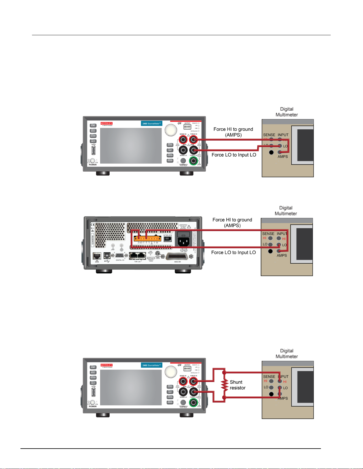
Connections for the 1 µA to 1 A ranges
For calibration verification or adjustment on the 1 µA to 1 A ranges, use either the front-panel or
rear-panel connections shown in the following figures.
Figure 3: Front-panel connections for the 1 µA to 1 A ranges
Figure 4: Rear-panel connections for the 1 µA to 1 A ranges
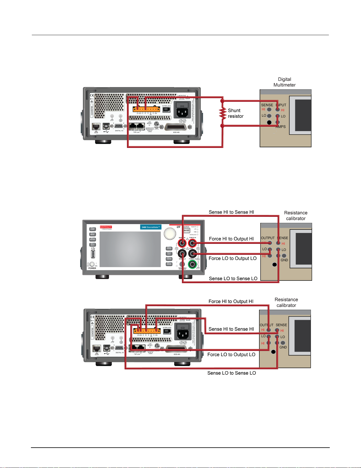
Connections for the 4 A to 7 A ranges
For calibration verification or adjustment on the 4 A to 7 A ranges, use either the front-panel or
rear-panel connections shown in the following figures.
Figure 5: Front-panel connections for the 4 A to 7 A ranges
2460-905-01 Rev. A / January 2016 2-5
Page 14
Section
Calibration and Adjustment Manual
2: Preparing for calibration verification and adjustment Model 2460
Figure 6: Rear-panel connections for the 4 A to 7 A ranges
Connections for resistance calibration verification and adjustment
For resistance calibration verification or adjustment, use either the front-panel or rear-panel
connections shown in the following figures.
Figure 7: Front-panel resistance connections
Figure 8: Rear-panel resistance connections
2-6 2460-905-01 Rev. A / January 2016
Page 15

Model 2460
paring for calibration verification and adjustment
Calibration and Adjustment Manual Section 2: Pre
Remote communications c onne c t ions
The procedures in this manual use SCPI commands sent to the Model 2460 from a remote interface.
Select one of the remote interface connections shown below. The instrument automatically detects
the connection. For more detailed information about the remote communications connections, see
"Remote communications interfaces" in the Model 2460 Reference Manual.
Figure 9: Remote communications interfaces
If you are using the IEEE-488 interface, make sure the primary address of the Model 2460 is the
same as the address specified in the program you will be using to send commands.
Calibration verification and adjustment considerations
When performing the calibration verification or adjustment procedures:
• Make sure that the test equipment is properly warmed up and connected to the Model 2460 input
and output jacks. Ensure that either the front-panel or rear-panel terminals are selected
(depending on your connections) with the TERMINALS FRONT/REAR button or using the
:ROUTe:TERMinals <FRONt or REAR> SCPI command.
• Make sure the Model 2460 is set to the correct source range.
• Make sure the Model 2460 output is turned on before making measurements.
• Make sure the test equipment is set up for the proper function and range.
• Allow the Model 2460 output signal to settle before making a measurement or adjusting each
point.
• When using a shunt resistor for current calibration verification and adjustment, make sure the
shunt is properly rated for the current and power being measured. Also, consider temperature
coefficient and other resistance uncertainty contributors in the overall measurement uncertainty
calculation.
• Do not connect test equipment to the Model 2460 through a scanner, multiplexer, or other
switching equipment.
2460-905-01 Rev. A / January 2016 2-7
Page 16

Remote calibration verification procedure ................................ 3-3
In this section:
Introduction .............................................................................. 3-1
Calibration verification limits ..................................................... 3-2
Setting the measurement range ............................................... 3-3
Taking the Model 2460 out of a limit overflow state ................. 3-3
Introduction
Use the procedures in this section to verify that Model 2460 accuracy is within the limits stated in the
instrument’s one-year accuracy specifications. Specifications and characteristics are subject to
change without notice; refer to the Downloads, Manuals, and Documentation web page
(http://www.tek.com/downloads
Section 3
Calibration
(http://www.tek.com/downloads)) for the most recent specifications.
You can use these calibration verification procedures to:
• Make sure that the instrument was not damaged during shipment
• Verify that the instrument meets factory specifications
• Determine if adjustment is required
• Verify that adjustment was done properly
The information in this section is intended for qualified service personnel only. Do not
attempt these procedures unless you are qualified to do so. Some of these procedures may
expose you to hazardous voltages, which could cause personal injury or death if contacted.
Use appropriate safety precautions when working with hazardous voltages.
If the instrument is still under warranty and its performance is outside specified limits, please contact
your local Keithley Instruments office, sales partner, or distributor. You can also call the corporate
headquarters of Keithley Instruments (toll-free inside the U.S. and Canada only) at 1-800-935-5595,
or from outside the U.S. at +1-440-248-0400. For worldwide contact numbers, visit the Keithley
Instruments website (http://www.tek.com/keithley).
Page 17

Section
Calibration and Adjustment Manual
3: Calibration Model 2460
Calibration verification limits
Before performing the calibration verification test procedures, you must calculate the calibration
verification limits using the Model 2460 specifications. The most recent version of the specifications is
on the Downloads, Manuals, and Documentation web page at http://www.tek.com/downloads
(http://www.tek.com/downloads).
In the Model 2460 Specifications document, source specifications are expressed as a percent of
setting plus voltage, current, or ohms offset. Measure specifications are expressed as a percent of
reading plus voltage, current, or ohms offset.
The calculation for calibration verification limits is:
Specification toleranc e = ± [(setting × percent of setting specification) + offset specification
To calculate the calibration verification limits for a range:
1. Select the test setting to verify.
2. Multiply the setting by the percent of setting (for source verification) or percent of reading (for
measure verification) value listed in the specification for that range.
3. Add the absolute value of that calculation to the offset specification for the range.
4. Calculate the low limit by subtracting the result of step 3 from the setting value.
5. Calculate the high limit by adding the result of step 3 to the setting value.
Example source limits calc ulation
As an example of how source limits are calculated, assume you are testing the 20 V DC range using
a 95 percent of scale signal value, and the Model 2460 one-year accuracy specification.
Use ±(0.015 % of setting + 2.4 mV offset) to get the calculated output limits:
Output limits = 19 V ± [(19 V × 0.015 %) + 2.4 mV]
Output limits = 19 V ± (0.00285 + 0.0024)
Output limits = 19 V ± 0.00525 V
Output limits = 18.99475 V to 19.00525 V
Example measure limits calculation
When you verify the measure functions (voltage, current, and resistance), calculate the upper and
lower test limits relative to the reference nominal value determined by the reference instrument. For
voltage and current, the reference nominal value is generally a reading from a reference digital
multimeter (DMM). For resistance, the reference value is the characterized value of the resistance
source.
The calculation of upper and lower test limits is identical to the source limit calculation, except the
reference value is used instead of the nominal setting.
As an example, assume that you are testing the 20 kΩ range, and the actual value of the nominal
19 kΩ calibrator resistor is 19.025 kΩ. Using a one-year normal accuracy specification of ±(0.063 %
of reading + 3 Ω), the recalculated reading limits are:
Specification tolerence = [(19.025 kΩ × 0.063 %) + 3 Ω]
Reading limits = 19.025 kΩ ±(11.99 kΩ + 3 Ω)
Reading limits = 19.025 kΩ ±14.99 Ω
Reading limits = 19.01001 kΩ to 19.03999 kΩ
3-2 2460-905-01 Rev. A / January 2016
Page 18

Model 2460
Calibration
Calibration and Adjustment Manual Section 3:
Setting the measurement range
When simultaneously sourcing and measuring either voltage or current, the measure range is
coupled to the source range, and you cannot independently control the measure range. As a result,
you do not set the range when testing voltage or current measurement accuracy.
When selecting the source range, be sure that the limit is set to the appropriate maximum value for
that range.
Taking the Model 2460 out of a limit overflow state
Calibration verification measurements should not be made when the Model 2460 is in a limit overflow
state. For purposes of the calibration verification tests, the Model 2460 can be taken out of an
overflow state by raising the limit value.
Do not take the instrument out of an overflow state by decreasing the source value or changing the
range. Always use the recommended range and source settings when verifying the instrument.
Remote calibration verification procedure
Use the following procedure to verify instrument calibration by sending SCPI commands over the
IEEE-488, USB, or LAN connections.
Step 1. Prepare the Model 2460 for calibration verification
Verify that the calibration verification environment, instrument, and test equipment are set up as
described in Preparing for calibration verification and adjustment (on page 2-1
Step 2. Voltage calibration verification
Follow the steps below to verify that Model 2460 voltage source-measure accuracy is within specified
limits. This test involves setting the output voltage to each full-range value and measuring the
voltages with a precision digital multimeter (DMM).
1. With the source output off, connect the Keithley Model 2460 to the DMM as shown in
Connections for the 200 mV to 100 V ranges (on page 2-4
Hazardous voltages may be present on all output and guard terminals. To prevent electrical
shock that could cause injury or death, never make or break connections to the Model 2460
while the instrument is powered on. Turn off the equipment from the front panel or
disconnect the main power cord from the rear of the Model 2460 before handling cables.
Putting the equipment into standby does not guarantee that the outputs are powered off if a
hardware or software fault occurs.
).
).
2460-905-01 Rev. A / January 2016 3-3
Page 19

Section
Calibration and Adjustment Manual
1
*RST
Restore default settings.
2
:SOUR:FUNC VOLT
Select the source function.
3
:FUNC "VOLT"
Select the measure function.*
4
:SOUR:VOLT:RANG <Range>
Set the source range.**
5
:SYST:RSEN OFF
Disable remote sensing.***
6
Select the front-panel or rear-panel terminals to
match your test setup.
7
:SOUR:VOLT <Level>
Program the source value.
8
:OUTP:STAT ON
Turn on the source output.
9
Make DMM reading.
Read the actual output of the Model 2460 using
the external DMM.
:READ?
source output.
11
:OUTP:STAT OFF
Turn off the source output.
step 9.
13
Calculate the measure error.
Calculate the difference between step 9 and
step 10.
14
Validate source accuracy.** **
Compare the result of step 12 to the source
specification.
specification.
* The measure range is coupled to the source range when simultaneously sourcing and measuring voltage,
Model 2460 (not the programmed value).
3: Calibration Model 2460
2. Turn on the source output.
If the Model 2460 is not already warmed up, allow it to warm up for at least one hour before
continuing to the next step.
Complete the range calibration verification steps listed in the following table for each voltage range.
For each voltage range, perform the complete procedure at 95 percent of the range's positive
full-scale value, then at 0 V, then at 95 percent of the range's negative full scale value, and then again
at 0 V. For example, for the 200 mV range, complete the procedure four times using each of the
following values, in this order: +190 mV, 0 V, −190 mV, 0 V.
Voltage calibration verification procedure
Step Command or procedure Description
:ROUT:TERM <FRONT or REAR>
10
Have the Model 2460 measure and return its
12 Calculate the source error. Calculate the difference between step 7 and
15 Validate measure accuracy.** ** * Compare the result of step 13 to the measure
so you do not neet to set the measure range.
** Where <Range> = 0.2, 2, 7, 10, 20, and 100.
*** With remote sense off, you may need to add a relative offset to compensate for cable noise.
**** The source limits are calculated based on the programmed source value of the Model 2460 for each range
(not the actual value).
***** The measure limits are calculated based on a precise measurement of the programmed value of the
3-4 2460-905-01 Rev. A / January 2016
Page 20

Model 2460
Calibration
Calibration and Adjustment Manual Section 3:
Step 3. Current calibra t ion verification
Keithley Instruments recommends two different connection configurations for current calibration
verification:
For the 1 µA to 1 A ranges, use the connection diagrams in Connections for the 1 µA to 1 A
ranges (on page 2-5).
For the 4 A to 7 A ranges, use the connection diagrams in Connections for the 4 A to 7 A ranges
(on page 2-5).
The following topics describe how to do current calibration verification for each of these
configurations.
Current calibration verification for the 1 µA to 1 A ranges
Follow the steps below to verify that Model 2460 current source-measure accuracy is within specified
limits. In this test, you set the output current to each full-range value and measure the current with a
precision digital multimeter (DMM).
To calibrate the 1 µA to 1 A ranges:
1. With the source output off, connect the Model 2460 to the DMM using the connection
configuration in Connections for the 1 µA to 1 A ranges (on page 2-5
).
Hazardous voltages may be present on all output and guard terminals. To prevent electrical
shock that could cause injury or death, never make or break connections to the Model 2460
while the instrument is powered on. Turn off the equipment from the front panel or
disconnect the main power cord from the rear of the Model 2460 before handling cables.
Putting the equipment into standby does not guarantee that the outputs are powered off if a
hardware or software fault occurs.
2. Turn on the Model 2460 source output.
If the Model 2460 is not already warmed up, allow it to warm up for at least one hour before
continuing to the next step.
3. Complete the range calibration steps listed in the following table for each current range. For each
current range, perform the complete procedure at 95 percent of the range's positive full-scale
value, then at 0 A, then at 95 percent of the range's negative full scale value, and then again at
0 A. For example, for the 1 mA range, complete the procedure four times using each of the
following values, in this order: +0.95 mA, 0 A, -0.95 mA, 0 A.
2460-905-01 Rev. A / January 2016 3-5
Page 21

Section
Calibration and Adjustment Manual
1
*RST
Restore default settings.
:SOUR:FUNC CURR
3
:FUNC "CURR"
Select the measure function.*
4
:SOUR:CURR:RANG <Range>
Set the source range.**
5
:SYST:RSEN OFF
Disable 4-wire remote sensing.
6
:ROUT:TERM <FRONT or REAR>
Select the front-panel or rear-panel terminals to
match your test setup.
7
:SOUR:CURR <Level>
Program the source value.
8
:OUTP:STAT ON
Turn on the source output.
9
Make DMM reading.
Read the actual output of the Model 2460 using
the external DMM.
10
:READ?
Have the Model 2460 measure and return its
11
:OUTP:STAT OFF
Turn off the source output.
12
Calculate the source error.
Calculate the difference between step 7 and
step 9.
13
Calculate the measure error.
Calculate the difference between step 9 and
step 10.
specification.
15
Validate measure accuracy.** **
Compare the result of step 13 to the measure
specification.
* The measure range is coupled to the source range when simultaneously sourcing and measuring current,
Model 2460 (not the programmed value).
3: Calibration Model 2460
Current calibration verification procedure for the 1 µA to 1 A ranges
Step Command or procedure Description
2
Select the source function.
source output.
14 Validate source accuracy.** * Compare the result of step 12 to the source
so you do not need to set the measure range.
** Where <Range> = 1e-6, 10e-6, 100e-6, 1e-3, 10e-3, 100e-3, and 1.
*** The source limits are calculated based on the programmed source value of the Model 2460 for each range
(not the actual value).
**** The measure limits are calculated based on a precise measurement of the programmed value of the
3-6 2460-905-01 Rev. A / January 2016
Page 22

Model 2460
Calibration
Calibration and Adjustment Manual Section 3:
Current calibration verification for the 4 A to 7 A ranges
Follow the steps below to verify that Model 2460 current source-measure accuracy is within specified
limits. In this test, you set the output current to each full-range value and measure the voltage drop
across a shunt resistor with a precision digital multimeter (DMM) and then calculate the current.
When verifying the 4 A to 7 A ranges using a shunt resistor, use the following formula to calculate
the current:
Current (I) = Voltage (V) / Resistance (R)
Where:
Resistance is either the value stated by the specifications for the shunt resistor, or for greater
measurement accuracy, resistance is the measured resistance value of the shunt resistor.
1. With the source output off, connect the Model 2460 to the DMM using the connection
configuration in Connections for the 4 A to 7 A ranges (on page 2-5
).
Hazardous voltages may be present on all output and guard terminals. To prevent electrical
shock that could cause injury or death, never make or break connections to the Model 2460
while the instrument is powered on. Turn off the equipment from the front panel or
disconnect the main power cord from the rear of the Model 2460 before handling cables.
Putting the equipment into standby does not guarantee that the outputs are powered off if a
hardware or software fault occurs.
2. Turn on the Model 2460 source output.
If the Model 2460 is not already warmed up, allow it to warm up for at least one hour before
continuing to the next step.
3. Complete the range calibration verification steps listed in the following table for each current
range. For each current range, perform the complete procedure at 95 percent of the range's
positive full-scale value, then at 0 A, then at 95 percent of the range's negative full scale value,
and then again at 0 A. For example, for the 5 A range, complete the procedure four times using
each of the following values, in this order: +4.75 A, 0 A, -4.75 A, 0 A.
2460-905-01 Rev. A / January 2016 3-7
Page 23

Section
Calibration and Adjustment Manual
1
*RST
Restore default settings.
2
:SOUR:FUNC CURR
Select the source function.
3
:FUNC "CURR"
Select the measure function.*
4
:SOUR:CURR:RANG <Range>
Set the source range.**
5
:SYST:RSEN OFF
Disable 4-wire remote sensing.
6
Select the front-panel or rear-panel terminals to
match your test setup.
7
:SOUR:CURR <Level>
Program the source value.
8
:OUTP:STAT ON
Turn on the source output.
9
Make DMM reading.
Read the actual output of the Model 2460 using
the external DMM.
11
:READ?
Have the Model 2460 measure and return its
source output.
12
:OUTP:STAT OFF
Turn off the source output.
13
Calculate the source error.
Calculate the difference between step 7 and
step 10.
step 11.
15
Validate source accuracy.** *
Compare the result of step 13 to the source
specification.
16
Validate measure accuracy.** **
Compare the result of step 14 to the measure
specification.
* The measure range is coupled to the source range when simultaneously sourcing and measuring current.
Model 2460 (not the programmed value).
3: Calibration Model 2460
Current calibration verification procedure for the 4 A to 7 A ranges
Step Command or procedure Description
:ROUT:TERM <FRONT or REAR>
10 (calculated I) = (DMM V reading) / R Calculate the shunt current.
14 Calculate the measure error. Calculate the difference between step 10 and
*** Where <Range> = 4, 5, and 7.
**** The source limits are calculated based on the programmed source value of the Model 2460 for each range
(not the actual source value).
***** The measure limits are calculated based on a precise measurement of the programmed value of the
Step 4. Resistance measurement calibration
Follow the steps below to verify that Model 2460 resistance measurement accuracy is within specified
limits. In this procedure, you apply accurate resistances from a resistance calibrator and then verify
that Model 2460 resistance measurements are within required limits.
1. With the source output off, connect the Model 2460 to the resistance calibrator using the
connection configuration in Connections for resistance calibration verification and adjustment
page 2-6).
Hazardous voltages may be present on all output and guard terminals. To prevent electrical
shock that could cause injury or death, never make or break connections to the Model 2460
while the instrument is powered on. Turn off the equipment from the front panel or
disconnect the main power cord from the rear of the Model 2460 before handling cables.
Putting the equipment into standby does not guarantee that the outputs are powered off if a
hardware or software fault occurs.
(on
3-8 2460-905-01 Rev. A / January 2016
Page 24

Model 2460
Calibration
1
*RST
Restore default settings.
2
:FUNC "RES"
Select the resistance function.
3
:RES:RANG:AUTO OFF
Disable autoranging.
4
:RES:RANG <Range>
Set the resistance range.
5
:RES:RSEN ON
Enable 4-wire remote sensing.
match your test setup.
7
Program calibrator value.
Set the resistance calibrator value.
8
:OUTP:STAT ON
Turn on the source output.
9
:READ?
Have the Model 2460 measure and return its
source output.
10
:OUTP:STAT OFF
Turn off the source output.
11
Calculate the measure error.
Calculate the difference between step 7 and
step 9.
12
Validate measure accuracy.
Compare the result of step 11 to the calibrator
* Perform the complete procedure for each range, where <Range> = 20, 200, 2K, 20K, 200K, 2M, 20M, and 200M.
Calibration and Adjustment Manual Section 3:
2. Turn on the Model 2460 source output.
If the Model 2460 is not already warmed up, allow it to warm up for at least one hour before
continuing to the next step.
3. On the resistance calibrator, select the external sense mode.
4. Send the commands summarized in the following table in the order listed to verify resistance
measurement accuracy.
Resistance calibration verification procedure using a resistance calibrator*
Step Command or procedure Description
6
:ROUT:TERM <FRONT or REAR>
Select the front-panel or rear-panel terminals to
specification.
It may not be possible to set the resistance calibrator to the specified value. Use the closest possible
setting and modify reading limits accordingly.
2460-905-01 Rev. A / January 2016 3-9
Page 25

Section
Calibration and Adjustment Manual
20 Ω
19 Ω
200 Ω
190 Ω
2 kΩ
1.9 kΩ
20 kΩ
19 kΩ
200 kΩ
190 kΩ
2 MΩ
1.9 MΩ
20 MΩ
19 MΩ
200 MΩ
100 MΩ
3: Calibration Model 2460
5. Verify that the Model 2460 resistance reading is within the limits in the following table.
Ohms measurement accuracy limits
Model 2460 range Calibrator resistance*
* Nominal resistance value.
3-10 2460-905-01 Rev. A / January 2016
Page 26
Single-range adjustment ........................................................ 4-16
In this section:
Introduction .............................................................................. 4-1
Unlocking calibration for adjustment ........................................ 4-1
Changing the password ........................................................... 4-2
Resetting the calibration password .......................................... 4-3
Querying calibration and adjustment dates and count ............. 4-3
Adjustment errors ..................................................................... 4-3
Remote adjustment .................................................................. 4-4
Remote adjustment procedure ................................................. 4-7
Introduction
Section 4
Adjustment
Use the procedures in this section to adjust the Model 2460. These procedures require accurate test
equipment to measure precise DC voltages and currents. Adjustment can be completed either from
the front panel or by sending SCPI calibration and adjustment commands over the IEEE-488, USB, or
LAN port using a computer. This manual describes using SCPI commands from a remote interface to
adjust the instrument.
The information in this section is intended for qualified service personnel only. Do not
attempt these procedures unless you are qualified to do so. Some of these procedures may
expose you to hazardous voltages, which could cause personal injury or death if contacted.
Use appropriate safety precautions when working with hazardous voltages.
Unlocking calibration for adjustment
Before adjusting the Model 2460, you must unlock the calibration constants by entering or sending a
password using the following command (KI002400 is the default pass wor d; if you have cha nge d
your password, use it instead):
CALibration:UNLock "KI002400"
When calibration constants are unlocked, the instrument is in the state shown in the following table. If
you try to change any of these settings with calibration unlocked, error +510, “Not permitted with cal
unlocked” is returned.
Page 27
Section
Calibration and Adjustment Manual
Concurrent functions
Off
:SENSe:FUNCtion:CONCurrent Off
Sense function sense
Source
:SENSe:FUNCtion <source_function>
:SENSe:VOLTage:NPLC 1.0
:SENSe:VOLTage:RANGe <source_v_range>
Current NPLC sense
1.0
:SENSe:CURRent:NPLC 1.0
Current measure range
Same as
range value
:SENSe:CURRent:RANGe <source_i_range>
Count
10
:SENSe:AVERage:COUNt 10
Filter control
Repeat
:SENSe:AVERage:TCONtrol Repeat
Filter averaging
On
:SENSe:AVERage:STATe On
Source V mode
Fixed
:SOURce:VOLTage:MODE Fixed
Volts autorange
Off
:SOURce:VOLTage:RANGe:AUTO Off
Source I mode
Fixed
:SOURce:CURRent:MODE Fixed
Current autorange
Off
:SOURce:CURRent:RANGe:AUTO Off
Autozero
On
:SYSTem:AZERo On
4: Adjustment Model 2460
With calibration unlocked, the sense function and the source function and range are the same. For
example, when :SOURce:FUNCtion is set to VOLTage, the :SENSe:FUNCtion setting is
"VOLTage:DC". When :SOURce:FUNCtion is set to CURRent, the :SENSe:FUNCtion setting is
"CURR:DC". This also applies to the range settings (for example,
:SOURce:VOLTage:RANGe and :SENSe:VOLTage:RANGe;
SOURce:CURRent:RANGe and :SENSe:CURRent:RANGe).
Calibration unlocked states
Mode State Equivalent remote command
Volts NPLC sense 1.0
Volts measure range Same as
source V
range value
Changing the password
You can change the default password from the front panel or using a remote interface.
To change the calibration password using SCPI commands, first send the present password, and
then send the new password.
For example, the following command sequence changes the password from the "KI002400" default
password to "KI_CAL":
CALibration:PASSword "KI002400"
CALibration:PASSword "KI_CAL"
source I
You can use any combination of letters and numbers up to a maximum of eight characters.
4-2 2460-905-01 Rev. A / January 2016
Page 28

M
odel 2460 Calibration and Adjustment Manual Section 4:
Adjustment
Resetting the calibration password
If you change the Model 2460 calibration password and forget it, you must return the Model 2460 to
the local Keithley Worldwide Service Center to be reset. There is no user-serviceable procedure to
restore the default calibration password on the Model 2460.
Querying calibration and adjustment dates and count
To query the adjustment date, send the following SCPI command:
CALibration:ADJust:DATE?
To query the number of times the Model 2460 has been adjusted, send the following SCPI command:
CALibration:ADJust:COUNt?
To query the calibration verification date, send the following SCPI command:
CALibration:VERify:DATE?
You can also view the calibration verification and adjustment dates and adjustment count on the front
panel by pressing the MENU key and selecting System Information.
Adjustment errors
The Model 2460 checks for errors after each adjustment step, minimizing improper adjustment due to
operator error.
Front-panel error rep orting
If an error is detected during adjustment, the instrument displays an appropriate error message. Once
the error is displayed, you can dismiss the error message and repeat the adjustment step that caused
the error with the corrected parameter or corrected command syntax.
Remote error reporti ng
You can detect errors while using a remote interface by testing the state of the Error Available Bit
(EAV) (bit 2) in the status byte (use the *STB? query to request the status byte). Query the
instrument for the type of error by using the appropriate :SYSTem:ERRor? query. The Model 2460
will respond with the error number and a text message describing the the error.
2460-905-01 Rev. A / January 2016 4-3
Page 29
Section
Calibration and Adjustment Manual
0.2 V
+200.00 mV
____________________________ mV
+000.00 mV
____________________________ mV
____________________________ mV
2 V
+2.0000 V
____________________________ V
+0.0000 V
____________________________ V
____________________________ V
7 V
+7.000 V
____________________________ V
+0.000 V
____________________________ V
____________________________ V
10 V
+10.00 V
____________________________ V
+0.000 V
____________________________ V
____________________________ V
____________________________ V
20 V
+20.000 V
____________________________ V
____________________________ V
____________________________ V
100 V
+100.00 V
____________________________ V
____________________________ V
____________________________ V
* DMM reading used in corresponding adjustment step. See procedure.
4: Adjustment Model 2460
Remote adjustment
Use the following procedure to perform remote adjustment by sending SCPI commands over the
IEEE-488, USB, or LAN connection. The remote commands and appropriate parameters are
separately summarized for each step.
You can use the following tables to document each calibration adjustment value as the calibration
adjustment procedure is executed.
Voltage calibration adjustment data table
Source range Source voltage Digital multimeter (DMM) voltage reading*
+00.000 V ____________________________ V
−200.00 mV
−000.00 mV
−2.0000 V
−0.0000 V
−7.000 V
−0.000 V
−10.00 V
−0.000 V
−20.000 V
−00.000 V
____________________________ mV
____________________________ V
____________________________ V
+000.00 V ____________________________ V
−100.00 V
−000.00 V
4-4 2460-905-01 Rev. A / January 2016
Page 30
Model 2460
Adjustment
+0.0000 μA
____________________________ μA
____________________________ μA
+00.000 μA
____________________________ μA
____________________________ μA
100 μA
+100.00 μA
____________________________ μA
+000.00 μA
____________________________ μA
____________________________ μA
1 mA
+1.0000 mA
____________________________ mA
____________________________ mA
____________________________ mA
10 mA
+10.000 mA
____________________________ mA
____________________________ mA
____________________________ mA
100 mA
+100.00 mA
____________________________ mA
____________________________ mA
____________________________ mA
1 A
+100.00 mA
____________________________ A
+000.00 mA
____________________________ A
____________________________ A
Calibration and Adjustment Manual Section 4:
Current calibration adjustment data table
Source range Source current DMM current reading*
1 μA +1.0000 μA ____________________________ μA
−1.0000 μA
−0.0000 μA
____________________________ μA
10 μA +10.000 μA ____________________________ μA
−10.000 μA
−00.000 μA
____________________________ μA
−100.00 μA
−000.00 μA
____________________________ μA
+0.0000 mA ____________________________ mA
−1.0000 mA
−0.0000 mA
+00.000 mA ____________________________ mA
−10.000 mA
+00.000 mA ____________________________ mA
2460-905-01 Rev. A / January 2016 4-5
−00.000 mA
−10.000 mA
−00.000 mA
−100.00 mA
−000.00 mA
____________________________ A
Page 31
Section
Calibration and Adjustment Manual
4 A
+4.0000 A
____________________________ A
+000.00 A
____________________________ A
____________________________ A
5 A
+5.0000 A
____________________________ A
+000.00 A
____________________________ A
____________________________ A
+000.00 A
____________________________ A
____________________________ A
* DMM reading used in corresponding adjustment step. See the adjustment procedure in Remote adjustment
4: Adjustment Model 2460
−4.0000 A
____________________________ A
−000.00 A
−5.0000 A
−000.00 A
____________________________ A
7 A +7.0000 A ____________________________ A
−7.0000 A
procedure (on page 4-7).
−000.00 A
____________________________ A
4-6 2460-905-01 Rev. A / January 2016
Page 32

Model 2460
Adjustment
:CALibration:PASSword
Unlock calibration:
default password is KI002400.
:CALibration:ADJust:COUNt?
Query the number of times the Model 2460
at the Keithley Instruments factory.
:CALibration:ADJust:DATE
:CALibration:ADJust:DATE?
Set or query the date the Model 2460 calibration
constants were last adjusted (year, month, day).
:CALibration:VERify:DATE
:CALibration:VERify:DATE?
Set or query the date the Model 2460 calibration
constants were last verified (year, month, day).
:CALibration:LOCK
:CALibration:LOCK?
Set or query whether or not the Model 2460
:CALibration:UNLock <password>
Unlock the Model 2460 calibration constants.
:CALibration:SAVE
Save the updated calibration constants to
nonvolatile memory.*
:CALibration:ADJust:SENSe
Set the new adjusted sense data value.
:CALibration:ADJust:SENSe:DATA?
:CALibration:ADJust:SOURce
Set the new adjusted source data value.
:CALibration:ADJust:SOURce:DATA?
Query the new adjusted source data.
* Adjustment data is not saved if calibration constants were not unlocked with the
:CALibration:UNLock <password>
Calibration and Adjustment Manual Section 4:
Calibration and adjust m e nt comm a nds summ a ry
The following table summarizes the Model 2460 calibration and adjustment commands. For more
detailed descriptions of the commands, see the Command reference (on page 5-1
SCPI command Description
* Changes the password if
<change code to unlock>
calibration constants are already unlocked. The
calibration constants have bee n adjust ed.
Note: The adjust count is incremented
automatically each time a customer adjustment
is completed. The adjust count can only be reset
calibration constants are locked or unlocked.
) section.
command.
If you change the default calibration password and you forget the new password, you must return the
Model 2460 to the Keithley Worldwide Service Center to reset the calibration password. This
password is unique to calibration and is not the same as the instrument password that is described in
the Model 2460 Reference Manual.
Remote adjustment procedure
Use the following procedure to adjust the Model 2460.
Step 1. Prepare the Model 2460 for adjustment
Verify that the adjustment environment, instrument, and test equipment are set up as described in
Preparing for calibration verification and adjustment (on page 2-1
Query the new adjusted sense data.
).
2460-905-01 Rev. A / January 2016 4-7
Page 33

Section
Calibration and Adjustment Manual
*RST
Restore instrument defaults.
:SOUR:FUNC VOLT
Activate the voltage source.
:SENS:CURR:RANG 0.1
Make sure the 1 A range is not active.
:SOUR:VOLT:PROT:LEV NONE
:SYST:RSEN OFF
Disable remote sensing.*
:CAL:UNL "KI002400"
Unlock the calibration constants.
match your test setup.
:OUTP:STAT ON
Turn the source output on.
4: Adjustment Model 2460
Step 2. Voltage adjustment
1. With the source output off, connect the Keithley Model 2460 to the digital multimeter (DMM) as
shown in Connections for the 200 mV to 100 V ranges (on page 2-4
Hazardous voltages may be present on all output and guard terminals. To prevent electrical
shock that could cause injury or death, never make or break connections to the Model 2460
while the instrument is powered on. Turn off the equipment from the front panel or
disconnect the main power cord from the rear of the Model 2460 before handling cables.
Putting the equipment into standby does not guarantee that the outputs are powered off if a
hardware or software fault occurs.
2. Turn on the Model 2460 source output.
If the Model 2460 is not already warmed up, allow it to warm up for at least one hour before
continuing to the next step.
3. On the DMM, select the DC volts function.
4. Initialize voltage adjustment by sending the commands summarized in the following table in the
order listed.
).
When the :CALibrate:UNLock command is sent, the instrument assumes the operating states
listed in the "Calibration unlocked states" table in Unlocking calibration for adjustment (on page 4-1).
Voltage adjustment initialization commands
Command Description
Allow maximum source voltage.
:ROUT:TERM <FRONT or REAR>
* Remote sensing may be used if desired, but is not essential when using recommended digital multimeter.
Select the front-panel or rear-panel terminals to
4-8 2460-905-01 Rev. A / January 2016
Page 34

Model 2460
Adjustment
Calibration and Adjustment Manual Section 4:
5. Complete the range adjustment steps listed in the following table for each range. Do the following
for each range:
Send the :SOURce:VOLTage:RANGe command to select the source and sense range to
adjust. For example, for the 2 V range, send the following command:
:SOUR:VOLT:RANG 2
Program the source to output the negative full-range value using the :SOURce:VOLTage
command. For example, send the following command:
:SOUR:VOLT -2
Record the DMM reading in the "Voltage calibration adjustment data" table in Remote
adjustment (on page 4-4).
Use the DMM reading as the parameter for the :CALibration:ADJust:SOURce and
:CALibration:ADJust:SENSe commands. For example, typical values for the 2 V range
would be:
:CAL:ADJ:SOUR -1.998
:CAL:ADJ:SENS -1.998
Set the voltage source to 0 V output using the :SOURce:VOLTage command:
:SOUR:VOLT 0.0
Record the DMM reading in the "Voltage calibration adjustment data" table in Remote
adjustment (on page 4-4).
Send the source and sense calibration adjustment commands using the DMM reading for the
parameter. For example:
:CAL:ADJ:SOUR 0.001
:CAL:ADJ:SENS 0.001
Set the source to the positive full-range value using the :SOURce:VOLTage command. For
example:
:SOUR:VOLT 2
Record the DMM reading in the "Voltage calibration adjustment data" table in Remote
adjustment (on page 4-4).
Send the source and sense commands using the DMM reading as the parameter. For
example:
:CAL:ADJ:SOUR 1.997
:CAL:ADJ:SENS 1.997
Send the :SOURce:VOLTage command to set the source voltage to 0 V:
:SOUR:VOLT 0.0
Record the DMM reading in the "Voltage calibration adjustment data" table in Remote
adjustment (on page 4-4).
Send the :CALibration:ADJust:SOURce command using the DMM reading as the
command parameter. For example:
:CAL:ADJ:SOUR -1.02e-3
2460-905-01 Rev. A / January 2016 4-9
Page 35

Section
Calibration and Adjustment Manual
1
:SOUR:VOLT:RANG <Range>
Select the source range.
2
:SOUR:VOLT -<Range>
Establish negative polarity.
3
DMM reading 1.**
Read the actual output value on the DMM.
4
:CAL:ADJ:SOUR <DMM_Reading1>
Adjust the source function negative full scale.
5
:SYST:ERR?
Check Model 2460 for errors.
6
:CAL:ADJ:SENS <DMM_Reading1>
Adjust the sense function negative full scale.
7
:SYST:ERR?
Check Model 2460 for errors.
8
:SOUR:VOLT 0.0
Set the output to 0 V.
9
DMM reading 2.**
Read the actual output value on the DMM.
10
:CAL:ADJ:SOUR <DMM_Reading2>
Adjust the source function negative zero.
11
:SYST:ERR?
Check Model 2460 for errors.
12
:CAL:ADJ:SENS <DMM_Reading2>
Adjust the sense function negative zero.
13
:SYST:ERR?
Check Model 2460 for errors.
14
:SOUR:VOLT +<Range>
Establish positive polarity.
15
DMM reading 3.**
Read the actual output value on the DMM.
16
CAL:ADJ:SOUR <DMM_Reading3>
Adjust the sense function positive full scale.
17
:SYST:ERR?
Check Model 2460 for errors.
18
CAL:ADJ:SENS <DMM_Reading3>
Adjust the source function positive full scale.
19
:SYST:ERR?
Check Model 2460 for errors.
20
:SOUR:VOLT 0.0
Set the output to 0 V.
21
DMM reading 4.**
Read the actual output value on the DMM.
22
:CAL:ADJ:SOUR <DMM_Reading4>
Adjust the source positive zero.
23
:SYST:ERR?
Check Model 2460 for errors.
<DMM_Readingn>
4: Adjustment Model 2460
Voltage range calibration and adjustment commands
Step Command Description
* Perform the complete procedure for each range, where <Range> = 0.2, 2, 7, 10, 20, and 100.
** The
parameter is the DMM reading from the previous step.
Each range requires:
Four CAL:ADJ:SOURce commands (full scale and zero for each polarity)
Three CAL:ADJ:SENSe commands (full scale for each polarity, and zero)
Step 3. Current adjustme nt
Keithley Instruments recommends two different connection configurations for current adjustment:
For the 1 µA to 1 A ranges, use the connection diagrams in Connections for the 1 µA to 1 A
ranges (on page 2-5).
For the 4 A to 7 A ranges, use the connection diagrams in Connections for the 4 A to 7 A ranges
(on page 2-5).
The following topics describe how to do current adjustment for each of these configurations.
4-10 2460-905-01 Rev. A / January 2016
Page 36

Model 2460
Adjustment
*RST
Restore instrument defaults.
:SOUR:FUNC CURR
Select the source current mode.
:FUNC "CURR"
Select the measure function.*
:CAL:UNL "KI002400"
Unlock the calibration constants.
your test setup.
:OUTP:STAT ON
Turn source output on.
* The measure range is coupled to the source range when simultaneously sourcing and measuring current,
Calibration and Adjustment Manual Section 4:
Current adjustment for the 1 µA to 1 A ranges
1. With the source output off, connect the Model 2460 to the digital multimeter (DMM) using the
connection configuration in Connections for the 1 µA to 1 A ranges (on page 2-5
Hazardous voltages may be present on all output and guard terminals. To prevent electrical
shock that could cause injury or death, never make or break connections to the Model 2460
while the instrument is powered on. Turn off the equipment from the front panel or
disconnect the main power cord from the rear of the Model 2460 before handling cables.
Putting the equipment into standby does not guarantee that the outputs are powered off if a
hardware or software fault occurs.
2. Turn on the Model 2460 source output.
If the Model 2460 is not already warmed up, allow it to warm up for at least one hour before
continuing to the next step.
3. On the DMM, select the DC current function.
4. Send the commands summarized in the following table in the order listed to initialize current
adjustment.
Current adjustment initialization commands
).
Command Description
:ROUT:TERM <FRONT or REAR>
so you do not need to set the measure range.
Select the front-panel or rear-panel terminals that match
2460-905-01 Rev. A / January 2016 4-11
Page 37

Section
Calibration and Adjustment Manual
4: Adjustment Model 2460
5. Adjust each current range using the procedure summarized in the following table. Do the
following for each range:
Send the :SOURce:CURRent:RANGe command to select the source and sense range to
adjust. For example, for the 1 mA range, the command is:
:SOUR:CURR:RANG 1e-3
Program the source to output the negative full-range value using the :SOURce:CURRent
command. For example:
:SOUR:CURR -1e-3
Record the DMM reading in the "Current calibration adjustment data" table in Remote
adjustment (on page 4-4).
Use the DMM reading as the parameter for the :CALibration:ADJ:SOURce and
:CALibration:ADJ:SENSe commands. For example, a typical value for the 1 mA range
would be:
:CAL:ADJ:SOUR -1.025e-3
:CAL:ADJ:SENS -1.025e-3
Set the current source to 0 A output using the :SOURce:CURRent 0.0 command.
Record the DMM reading in the "Current calibration adjustment data" table in
adjustment (on page 4-4).
Remote
Send the source and sense adjustment commands using the DMM reading for the parameter.
For example:
:CAL:ADJ:SOUR 1e-6
:CAL:ADJ:SENS 1e-6
Set the source to the positive full-range value using the :SOURce:CURRent command. For
example, for the 1 mA range:
:SOUR:CURR 1e-3
Record the DMM reading in the "Current calibration adjustment data" table in Remote
adjustment (on page 4-4).
Send the source and sense commands using the DMM reading as the parameter. For
example:
:CAL:ADJ:SOUR 1.03e-3
:CAL:ADJ:SENS 1.03e-3
Send the :SOURce:CURRent command to set the source current to 0 A:
:SOURce:CURRent 0.0
Record the DMM reading in the "Current calibration adjustment data" table in Remote
adjustment (on page 4-4).
Send the :CALibration:ADJ:SOURce command using the DMM reading as the command
parameter. For example:
:CAL:ADJ:SOUR -1.02e-3
4-12 2460-905-01 Rev. A / January 2016
Page 38

Model 2460
Adjustment
1
:SOUR:CURR:RANG <Range>
Select the source range.
:SOUR:CURR -<Range>
3
DMM reading 1.**
Read the actual output value on the DMM.
4
CAL:ADJ:SOUR <DMM_Reading>
Adjust the source function negative full scale.
5
:SYSTem:ERRor?
Check Model 2460 for errors.
6
CAL:ADJ:SENS <DMM_Reading>
Adjust the sense function negative full scale.
7
:SYSTem:ERRor?
Check Model 2460 for errors.
8
:SOUR:CURR 0.0
Set the output to 0 A.
9
DMM reading 2.**
Read the actual output value on the DMM.
10
:CAL:ADJ:SOUR <DMM_Reading>
Adjust the source function negative zero.
11
:SYSTem:ERRor?
Check Model 2460 for errors.
12
:CAL:ADJ:SENS <DMM_Reading>
Adjust the sense function negative zero.
13
:SYSTem:ERRor?
Check Model 2460 for errors.
14
:SOUR:CURR +<Range>
Establish positive polarity.
15
DMM reading 3.**
Read the actual output value on the DMM.
16
:CAL:ADJ:SOUR <DMM_Reading>
Adjust the sense function positive full scale.
17
:SYSTem:ERRor?
Check Model 2460 for errors.
18
:CAL:ADJ:SENS <DMM_Reading>
Adjust the source function positive full scale.
19
:SYSTem:ERRor?
Check Model 2460 for errors.
20
:SOUR:CURR 0.0
Set the output to 0 A.
21
DMM reading 4.**
Read the actual output value on the DMM.
22
:CAL:ADJ:SOUR <DMM_Reading>
Adjust the source positive zero.
23
:SYSTem:ERRor?
Check Model 2460 for errors.
* Perform the complete procedure for each range, where <Range> = 1e-6, 10e-6, 100e-6, 1e-3, 10e-3, 100e-3, and 1.
Calibration and Adjustment Manual Section 4:
Current range calibration and adjustment commands
Step Command/procedure* Description
2
** The <DMM_Readingn> parameter is the DMM reading from the previous step.
Establish negative polarity.
Current adjustment for the 4 A to 7 A ranges
When adjusting the 4 A to 7 A ranges using a shunt resistor, use the following formula to calculate
the current:
Current = Voltage / Resistance
Be sure to include shunt resistance uncertainty in the measurement uncertainty calculation when
using a current shunt.
1. With the source output off, connect the Model 2460 to the digital multimeter (DMM) using the
connection configuration in Connections for the 4 A to 7 A ranges (on page 2-5
2. Turn on the Model 2460 source output.
If the Model 2460 is not already warmed up, allow it to warm up for at least one hour before
continuing to the next step.
3. On the DMM, select the DC current function.
).
2460-905-01 Rev. A / January 2016 4-13
Page 39

Section
Calibration and Adjustment Manual
*RST
Restore instrument defaults.
:SOUR:FUNC CURR
Select the source current mode.
:FUNC "CURR"
Select the measure function.*
:CAL:UNL "KI002400"
Unlock the calibration constants.
setup.
:OUTP:STAT ON
Turn source output on.
* The measure range is coupled to the source range when simultaneously sourcing and measuring current,
so you do not need to set the measure range.
4: Adjustment Model 2460
4. Send the commands summarized in the following table in the order listed to initialize current
adjustment.
Current adjustment initialization commands
Command Description
:ROUT:TERM <FRONT or REAR>
Select the front or rear-panel terminals that match your test
5. Adjust each current range using the procedure summarized in the following table. Do the
following for each range:
Send the :SOURce:CURRent:RANGe command to select the source and sense range to
adjust. For example, for the 4 A range, the command is:
:SOUR:CURR:RANG 4
Program the source to output the negative full-range value using the :SOURce:CURRent
command. For example:
:SOUR:CURR -4
Measure the voltage across the shunt resistor, and then calculate the current.
Record the calculated current reading in the "Current calibration adjustment data" table in
Remote adjustment (on page 4-4
).
Use the calculated current value as the parameter for the
:CALibration:ADJustment:SOURce and :CALibration:ADJustment:SENSe
commands. For example, a typical value for the 4 A range would be:
:CAL:ADJ:SOUR -4.025
:CAL:ADJ:SENS -4.025
Set the current source to 0 A output using the :SOURce:CURRent command:
:SOURce:CURRent 0.0
• Measure the voltage across the shunt resistor, and then calculate the current.
Record the calculated current reading in the "Current calibration adjustment data" table in
Remote adjustment (on page 4-4
).
Send the source and sense adjustment commands using the calculated current reading for
the parameter. For example:
:CAL:ADJ:SOUR 1e-6
:CAL:ADJ:SENS 1e-6
Set the source to the positive full-range value using the :SOURce:CURRent command. For
example, for the 4 A range:
:SOUR:CURR 4
Measure the voltage across the shunt resistor, and then calculate the current.
Record the calculated current reading in the "Current calibration adjustment data" table in
Remote adjustment (on page 4-4
).
Send the source and sense commands using the DMM reading as the parameter. For
example:
4-14 2460-905-01 Rev. A / January 2016
Page 40

Model 2460
Adjustment
1
:SOUR:CURR:RANG <Range>
Select the source range.
2
:SOUR:CURR -<Range>
Establish negative polarity.
3
DMM reading 1.**
Using the DMM, measure voltage across the shunt
resistor.
4
(calculated I) = V (DMM reading 1) / R
Calculate the shunt resistor current.* **
5
:CAL:ADJ:SOUR <calculated I>
Adjust the source function negative full scale.
6
:SYSTem:ERRor?
Check Model 2460 for errors.
7
:CAL:ADJ:SENS <calculated I>
Adjust the sense function negative full scale.
8
:SYSTem:ERRor?
Check Model 2460 for errors.
9
:SOUR:CURR 0.0
Set the output to 0 A.
10
DMM reading 2.**
Using the DMM, measure the voltage across the
shunt resistor.
11
(calculated I) = V (DMM reading 2) / R
Calculate the shunt resistor current.
12
:CAL:ADJ:SOUR <calculated I>
Adjust the source function negative zero.
13
:SYSTem:ERRor?
Check Model 2460 for errors.
14
:CAL:ADJ:SENS <calculated I>
Adjust the sense function negative zero.
15
:SYSTem:ERRor?
Check Model 2460 for errors.
16
:SOUR:CURR +<Range>
Establish positive polarity.
17
DMM reading 3.**
Using the DMM, measure voltage across the shunt
18
(calculated I) = V (DMM reading 3) / R
Calculate the shunt resistor current.
19
:CAL:ADJ:SOUR <calculated I>
Adjust the sense function positive full scale.
20
:SYSTem:ERRor?
Check Model 2460 for errors.
21
:CAL:ADJ:SENS <calculated I>
Adjust the source function positive full scale.
22
:SYSTem:ERRor?
Check Model 2460 for errors.
23
:SOUR:CURR 0.0
Set the output to 0 A.
24
DMM reading 4.**
Using the DMM, measure the voltage across the
shunt resistor.
25
(calculated I) = V (DMM reading 4) / R
Calculate the shunt resistor current.
26
:CAL:ADJ:SOUR <calculated I>
Adjust the source positive zero.
27
:SYSTem:ERRor?
Check Model 2460 for errors.
* Perform the complete procedure for each range, where <Range> = 4, 5, and 7.
than using manufacturer specifications) and use that value in the shunt resistor current calculation.
Calibration and Adjustment Manual Section 4:
:CAL:ADJ:SOUR 4.03
:CAL:ADJ:SENS 4.03
Send the :SOURce:CURRent command to set the source current to 0 A:
:SOUR:CURR 0.0
Measure the voltage across the shunt resistor, and then calculate the current.
Record the calculated current reading in the "Current calibration adjustment data" table in
Remote adjustment (on page 4-4
).
Send the :CALibration:ADJustment:SOURce command using the calculated current
value as the command parameter. For example:
:CAL:ADJ:SOUR -1.02e-3
Current range calibration adjustment commands
Step Command/procedure* Description
resistor.
** The <DMM_Readingn> parameter is the DMM reading from the previous step.
*** To get more accurate readings when using a shunt resistor, measure the resistance of the shunt resistor (rather
2460-905-01 Rev. A / January 2016 4-15
Page 41

Section
tment Manual
4: Adjustment Model 2460 Calibration and Adjus
Step 4. Program calibration verification and adjustment dates
Use the following commands to set the calibration verification and adjustment dates.
:CALibration:VERification:DATE <year>, <month>, <day> (calibration date)
:CALibration:ADJust:DATE <year>, <month>, <day> (adjust date)
Note that the year, month, and day must be separated by commas. The allowable range for the year
is from 1995 to 2094, the month is from 1 to 12, and the day is from 1 to 31. The calibration date is
the same as a calibration without adjustment, otherwise known as verification.
The adjustment count is automatically incremented each time a customer calibration adjustment is
executed and the adjustment date is set with the commands above. Calling the
CALibration:ADJust:DATE and CALibration:SAVE commands in sequence automatically
increments the adjustment count. The Model 2460 may need to be power cycled before the new
dates will show on the front-panel display.
Step 5. Save calibrati on const a nt s
Adjustment is now complete, so you can store the calibration constants in nonvolatile memory by
sending the following command:
CALibration:SAVE
Adjustment is temporary unless you send the :SAVE command. Also, adjustment data is not saved if
calibration is locked, invalid data exists, or all steps were not completed.
Step 6. Lock-out adjustment
To lock out further adjustment, send the following command after completing the adjustment
procedure:
CALibration:LOCK
Single-range adjustment
Normally, the complete adjustment procedure should be performed to ensure that the entire
instrument is properly adjusted. In some instances, however, you may want to adjust only certain
ranges.
To adjust only some of the ranges, complete the entire unlock, adjust, save, and lock procedure for
the range or ranges to be adjusted. Note that you must complete all four source adjustment steps and
all three sense adjustment steps for each range to be adjusted. Also, be sure to set calibration
verification and adjustment dates and save calibration constants after adjusting the ranges.
4-16 2460-905-01 Rev. A / January 2016
Page 42
Model 2460 calibration verifica tion and adju st ment comm and s 5-1
Query only
Not applicable
Not applicable
Not applicable
:CAL:ADJ:COUN?
two times.
In this section:
Introduction .............................................................................. 5-1
Introduction
This section contains detailed information about the Model 2460 remote calibration verification and
adjustment commands, error messages, and methods to detect the end of each adjustment step.
Section 5
Command reference
See Adjustment (on page 4-1
) for detailed calibration adjustment procedures.
Model 2460 calibration verification and adjustment commands
Model 2460 calibration verification and adjustment commands are used to save calibration constants,
lock out calibration, and program date parameters.
:CALibration:ADJust:COUNt?
This command queries the number of times the Model 2460 has been adjusted.
Type Affected by Where saved Default value
Usage
CALibration:ADJust:COUNt?
Details
Use this command to determine the total number of times the instrument has been adjusted.
Example
Request the calibration adjustment count.
Output:
2
Indicates that the instrument has been adjusted
Also see
:CALibration:ADJust:DATE (on page 5-2)
Page 43
Section
Calibration and Adjustment Manual
<year>
1995
2094
<month>
<day>
:CAL:ADJ:DATE 2015, 11, 18
Set the adjustment date to November 18, 2015.
2015,11,18
5: Command reference Model 2460
:CALibration:ADJust:DATE
This command stores the user-specified adjustment date.
Type Affected by Where saved Default value
Command and query Not applicable Nonvolatile memory Not applicable
Usage
:CALibration:ADJust:DATE <year>, <month>, <day>
:CALibration:ADJust:DATE?
The year the instrument was adjusted;
The month the instrument was adjusted; 1 to 12
The day the instrument was adjusted; 1 to 31
Details
Use this command to store the adjustment date in the instrument nonvolatile memory. Calibration
constants must be unlocked with the :CALibration:UNLock command before sending this
command.
to
Example
Also see
You must send the :CALibration:SAVE command after making changes, or your changes will not
be saved through a power cycle.
The year, month, and day parameters must be delimited by commas.
You can use the query form of this command to get the last saved adjustment date.
:CAL:SAVE
:CAL:ADJ:DATE?
Save the adjustment date.
Query the adjustment date.
Output:
:CALibration:PASSword (on page 5-7)
:CALibration:SAVE (on page 5-8)
:CALibration:UNLock (on page 5-9)
5-2 2460-905-01 Rev. A / January 2016
Page 44

Model 2460
and reference
<range>
The sense range to adjust
<negZero>
The negative zero value of the selected range (from digital multimeter reading)
<negFullScale>
The negative full-scale value of the selected range (from digital multimeter reading)
<posZero>
<posFullScale>
The positive full-scale value of the selected range (from digital multimeter reading)
Calibration and Adjustment Manual Section 5: Comm
:CALibration:ADJust:SENSe
This command adjusts the sense function.
Type Affected by Where saved Default value
Command only Not applicable Nonvolatile memory Not applicable
Usage
CALibration:ADJust:SENSe <range>
CALibration:ADJust:SENSe <negZero>
CALibration:ADJust:SENSe <negFullScale>
CALibration:ADJust:SENSe <posZero>
CALibration:ADJust:SENSe <posFullScale>
The positive zero value of the selected range (from digital multimeter reading)
Details
Calibration constants must be unlocked with the :CALibration:UNLock command before sending
this command.
To use this command:
1. Set the source output value.
2. Select the range to adjust.
3. Send the CALibration:ADJust:SENSe command with each of the parameters in the usage
table above.
4. Repeat this procedure for each of the ranges.
If the specified parameters do not fit within the allowed ranges for the parameter, error -222,
"Parameter data out of range" is generated. Once the Model 2460 has successfully selected the
appropriate parameter range, it checks to see if autorange for the active sense function is enabled. If
it is enabled, error -221, "Settings conflict" is generated. If no error occurs, that active sense function
range point is adjusted using the corresponding parameter.
You must send the :CALibration:SAVE command after making changes, or your changes will not
be saved through a power cycle.
Parameters for a given sense function and range may be sent in any order. However, once one
CALibration:ADJust:SENSe command executes, the other parameters must also be executed or
an error -200, “Execution error” is generated when the CALibration:SAVE command is processed
at the end of the adjustment procedure.
2460-905-01 Rev. A / January 2016 5-3
Page 45
Section
Calibration and Adjustment Manual
CAL:ADJ:SENS +2.00003
Adjust the 2 V sense range.
Query only
Not applicable
Not applicable
Not applicable
:SENS:FUNC "CURR:DC"
Select the DC current sense function.
7.058321E-06,+0.000000E+00
5: Command reference Model 2460
Example
Also see
:CALibration:ADJust:SENSe:DATA? (on page 5-4)
:CALibration:SAVE (on page 5-8)
:CALibration:UNLock (on page 5-9)
:CALibration:ADJust:SENSe:DATA?
This command queries the calibration constants for the active sense range.
Type Affected by Where saved Default value
Usage
CALibration:ADJust:SENSe:DATA?
Details
This command requests the calibration constants for the active range of the sense function.
Constants returned are the positive full-scale value, the positive zero value, the negative full-scale
value, and negative zero value.
Example
Also see
The returned constants are in comma-delimited ASCII floating-point format.
:SENS:VOLT:DC:RANG 0.2
:CAL:ADJ:SENS:DATA?
Select the 200 mV range.
Request the calibration constants.
Example output:
-7.058334E-06,-1.790742E-10,-
:CALibration:ADJust:SENSe (on page 5-3)
5-4 2460-905-01 Rev. A / January 2016
Page 46
Model 2460
Command reference
<range>
The source range to adjust
<negZero>
The negative zero value of the selected range (from digital multimeter reading)
<negFullScale>
The negative full-scale value of the selected range (from digital multimeter reading)
<posZero>
The positive zero value of the selected range (from digital multimeter reading)
<posFullScale>
CAL:ADJ:SOUR +2.00003
Adjust the 2 V source range.
Calibration and Adjustment Manual Section 5:
:CALibration:ADJust:SOURce
This command adjusts the source function.
Type Affected by Where saved Default value
Command only Not applicable Nonvolatile memory Not applicable
Usage
CALibration:ADJust:SOURce <range>
CALibration:ADJust:SOURce <negZero>
CALibration:ADJust:SOURce <negFullScale>
CALibration:ADJust:SOURce <posZero>
CALibration:ADJust:SOURce <posFullScale>
The positive full-scale value of the selected range (from digital multimeter reading)
Details
Example
Also see
Calibration constants must be unlocked with the :CALibration:UNLock command before sending
this command.
If the specified parameters do not fit within the allowed ranges for the parameter, error -222,
"Parameter data out of range" is generated. Once the Model 2460 has successfully selected the
appropriate parameter range, it checks to see if autorange for the active source function is enabled
and that the output state is set to ON. If autorange is enabled or the output is set to OFF, error -221,
"Settings conflict" is generated. If no error occurs, the specified range point for the active source
function is adjusted using the corresponding param eter .
You must send the :CALibration:SAVE command after making changes, or your changes will not
be saved through a power cycle.
Because the source is adjusted for both positive and negative values, two zero adjustment points are
required. The Model 2460 automatically uses the appropriate zero parameter based on whether the
source polarity is positive or negative.
:CALibration:ADJust:SOURCe:DATA? (on page 5-6)
:CALibration:SAVE (on page 5-8)
:CALibration:UNLock (on page 5-9)
2460-905-01 Rev. A / January 2016 5-5
Page 47
Section
Calibration and Adjustment Manual
:SENS:FUNC CURR
Select the current source function.
-3.018662E+05,+1.248219E+03
Command and query
Not applicable
Nonvolatile memory
0
Query returns
0
1 = Calibration locked
5: Command reference Model 2460
:CALibration:ADJust:SOURCe:DATA?
This command queries the calibration constants for the active source range.
Type Affected by Where saved Default value
Query only Not applicabl e Not applicable Not applicable
Usage
CALibration:ADJust:SOURce:DATA?
Details
This command requests the calibration constants for the active range of the source function.
Constants returned are the positive full-scale value, the positive zero value, the negative full-scale
value, and negative zero value.
The returned constants are in comma-delimited ASCII floating-point format.
Example
:SENS:VOLT:RANG 1
:CAL:ADJ:SOUR:DATA?
Select the 1 A range.
Request the calibration constants.
Example output:
+3.018486E+05,+1.297160E+03,
Also see
:CALibration:ADJust:SOURce (on page 5-5)
:CALibration:LOCK
This command locks calibration constants.
Type Affected by Where saved Default value
Usage
CALibration:LOCK
CALibration:LOCK?
= Calibration unlocked
Details
Use this command to prevent comprehensive adjustment.
Send the CALibration:LOCK? query to determine if the calibration constants are locked.
Calibration constants are locked if 1 is returned; calibration constants are unlocked if 0 is returned.
If you change the Model 2460 calibration password and forget it, you must return the Model 2460 to
the local Keithley Worldwide Service Center to be reset. There is no user-serviceable procedure to
restore the default calibration password on the Model 2460.
5-6 2460-905-01 Rev. A / January 2016
Page 48

Model 2460
Command reference
:CAL:LOCK
Lock the calibration constants.
<password>
KI2400
:CAL:PASS "KI002400"
Send the existing password.
Cal123
Calibration and Adjustment Manual Section 5:
Example
Also see
:CALibration:PASSword (on page 5-7)
:CALibration:UNLock (on page 5-9)
:CALibration:PASSword
This command changes the calibration password.
Type Affected by Where saved Default value
Command only Not applicable Nonvolatile memory KI002400
Usage
CALibration:PASSword "<password>"
The calibration password; can contain up to 8 character s; default is
Details
Example
Also see
Use this command to change the calibration password, which is used to lock the calibration
constants.
To change the password, you must first send the existing password, and then send the command
again with the new password.
The password parameter must be enclosed in quotation marks.
:CAL:PASS "Cal123"
Send the command again with the new
password; password is changed to
.
:CALibration:LOCK (on page 5-6)
:CALibration:UNLock (on page 5-9)
2460-905-01 Rev. A / January 2016 5-7
Page 49

Section
Calibration and Adjustment Manual
:CAL:SAVE
Save the calibration constants.
5: Command reference Model 2460
:CALibration:SAVE
This command saves calibration constants to nonvolatile memory after completing the adjustment procedure.
Type Affected by Where saved Default value
Command and query Not applicable Nonvolatile memory Not applicable
Usage
:CALibration:SAVE
:CALibration:SAVE?
Details
Use this command to store internally calculated calibration constants that were derived during the
comprehensive adjustment procedure to nonvolatile memory. Calibration constants are retained
indefinitely once saved.
The :CALibration:SAVE command is usually sent after all other adjustment steps have been
completed, but before sending the :CALibration:LOCK command.
Adjustment is only temporary until the :CALibration:SAVE command is sent to permanently store
the calibration constants.
Example
Also see
Adjustment data will not be saved if one of the following conditions occurs:
• Calibration was not unlocked by sending the :CALibration:UNLock command before
adjustment
• Invalid data exists (for example, an adjustment step failed or was aborted)
• An incomplete number of adjustment steps were performed (for example, if a negative full-scale
step was omitted)
:CALibration:LOCK (on page 5-6)
:CALibration:UNLock (on page 5-9)
5-8 2460-905-01 Rev. A / January 2016
Page 50

Model 2460
Command reference
<password>
KI002400
:CAL:UNL "KI002400"
Unlock the calibration constants.
Command and query
Not applicable
Nonvolatile memory
Not applicable
<year>
The year the instrument was verified; 1995 to 2094
<month>
The month the instrument was verified; 1 to 12
<day>
The day the instrument was verified; 1 to 31
Calibration and Adjustment Manual Section 5:
:CALibration:UNLock
This command unlocks the calibration constants.
Type Affected by Where saved Default value
Command only Not applicable Nonvolatile memory Not applicable
Usage
:CALibration:UNLock "<password>"
The calibration password; the default password is
Details
Use this command to unlock the calibration constants so that comprehensive adjustment can be
done.
Send the CALibration:LOCK? query to determine if the calibration constants are locked.
Calibration constants are locked if 1 is returned; calibration constants are unlocked if 0 is returned.
The password parameter must be enclosed in quotation marks.
Example
Also see
:CALibration:LOCK (on page 5-6)
:CALibration:PASSword (on page 5-7)
:CALibration:VERify:DATE
This command stores the user-specified calibration verification date.
Type Affected by Where saved Default value
Usage
:CALibration:VERify:DATE <year>, <month>, <day>
:CALibration:VERify:DATE?
Details
Use this command to store the calibration verification date in the instrument nonvolatile memory.
Calibration constants must be unlocked with the :CALibration:UNLock command before sending
this command.
You must send the :CALibration:SAVE command after making changes, or your changes will not
be saved through a power cycle.
The year, month, and day parameters must be delimited by commas.
2460-905-01 Rev. A / January 2016 5-9
Page 51

Section
Calibration and Adjustment Manual
:CAL:VER:DATE 2015, 11, 18
Set the calibration verification date to November
2015,11,18
5: Command reference Model 2460
Example
You can use the query form of this command to get the last saved calibration verification date.
Also see
:CAL:SAVE
:CAL:VER:DATE?
:CALibration:PASSword (on page 5-7)
:CALibration:SAVE (on page 5-8)
:CALibration:UNLock (on page 5-9)
18, 2015.
Save the calibration verification date.
Query the calibration verification date.
Output:
5-10 2460-905-01 Rev. A / January 2016
Page 52

Line fuse replacement .............................................................. 6-1
In this section:
Introduction .............................................................................. 6-1
Introduction
Section 6
Routine maintenance
The information in this section describes routine maintenance that can be done by the operator.
Line fuse replacement
A fuse located on the Model 2460 rear panel protects the power line input of the instrument.
Disconnect the line cord at the rear panel and remove all test leads connected to the
instrument before replacing the line fuse. Failure to do so could expose the operator to
hazardous voltages that could result in personal injury or death.
Use only the correct fuse type. Failure to do so could result in injury, death, or instrument
damage.
Use a 5 x 20 mm slow-blow fuse rated at 250 V at 4 A.
To replace the fuse, you will need a small flat-bladed screwdriver.
Complete the following steps to replace the line fuse:
1. Power off the instrument.
2. Remove all test leads connected to the instrument.
3. Remove the line cord.
4. Locate the fuse drawer, which is above the AC receptacle, as shown in the figure below.
Figure 10: Model 2460 line fuse
Page 53

Section
n and Adjustment Manual
6: Routine maintenance Model 2460 Calibratio
5. Use the screwdriver to lift the tab from the fuse drawer.
6. Slide the fuse drawer out. The fuse drawer does not pull completely out of the power module.
7. Snap the fuse out of the drawer.
8. Replace the fuse.
9. Push the fuse drawer back into the module.
If the fuse continues to become damaged, a circuit malfunction exists and must be corrected. Return
the instrument to Keithley Instruments for repair.
6-2 2460-905-01 Rev. A / January 2016
Page 54

All Keithley trademarks and trade names are the property of Keithley Instruments.
All other trademarks and trade names are the property of their respective companies.
Specifications are subject to change without notice.
Corporate Headquarters • 28775 Aurora Road • Cleveland, Ohio 44139 • 440-248-0400 • Fax: 440-248-6168 • 1-800-935-5595 • www.tek.com/keithley
Keithley Instruments
A Greater Measure of Confidence
12/15
 Loading...