

Page 1
Tektronix
'*■ *
x^^#^;r^>:^:?r
/v^rT;
2445B/2455B/2465B
Oscilloscope and Options
Operator Manual
070-6860-00
-
r«
.-Tpta-S^i f *
"i -
j*.'<}<*'
Page 2
Tektronix
/
2445B/2455B/2465B
Oscilloscope and Options
Operator Manual
070-6860-00
Please check for change information at the rear
of
this
manual.
First Printing: May 1988
Revised Printing: October 1990
Page 3
Instrument Serial Numbers
Each instrument manufactured by Tektronix has a serial number on a panel
insert or tag, or stamped on the chassis. The first letter in the serial number
designates the country of manufacture. The last five digits of the serial number
are assigned sequentially and are unique to each instrument. Those
manufactured in the United States have six unique digits. The country of
manufacture is identified as follows:
B010000 Tektronix, Inc., Beaverton, Oregon, USA
E200000 Tektronix United Kingdom, Ltd., London
J300000 Sony/Tektronix, Japan
H700000 Tektronix Holland, NV, Heerenveen, The Netherlands
Instruments manufactured for Tektronix by external vendors outside the United
States are assigned a two digit alpha code to identify the country of manufacture
(e.g.,
JP for Japan, HK for Hong Kong, IL for Israel, etc.).
Tektronix, Inc., P.O. Box 500, Beaverton, OR 97077
Printed in
U.S.A.
Copyright
■!■
Tektronix, Inc., 1988
Page 4
WARRANTY
Tektronix warrants that this product will be free from defects in materials and
workmanship for a period of
three
(3) years from the date of shipment. If any such
product proves defective during this warranty
period,
Tektronix, at its
option,
either
will repair the defective product without charge for parts and
labor,
or
wiii
provide a
replacement in exchange for the defective product.
In order
to
obtain service under this warranty, Customer must notify Tektronix of the
defect before the expiration of the warranty period and make suitable
arrangements for the performance of service. Customer shall be responsible for
packaging and shipping the defective product to the service center designated by
Tektronix, with shipping charges prepaid. Tektronix shall pay for the return of the
product to Customer if
the
shipment
is
to a location within the country in which the
Tektronix service center is located. Customer shall be responsible for paying all
shipping charges, duties, taxes, and any other charges for products returned to
any other locations.
This warranty shall not apply to any defect, failure or damage caused by improper
use or improper or inadequate maintenance and care. Tektronix shall not be
obligated to furnish service under this warranty
a)
to repair damage resulting from
attempts by personnel other than Tektronix representatives to install, repair or
service the product; b) to repair damage resulting from improper use or connection
to incompatible equipment; or c) to service a product that has been modified or
integrated with other products when the effect of such modification or integration
increases the time or difficulty of servicing the product.
THIS WARRANTY IS GIVEN BY TEKTRONIX WITH RESPECT TO THIS
PRODUCT IN LIEU OF ANY OTHER WARRANTIES, EXPRESSED OR
IMPLIED. TEKTRONIX AND ITS VENDORS DISCLAIM ANY IMPLIED
WARRANTIES OF MERCHANTABILITY OR FITNESS FOR A PARTICULAR
PURPOSE. TEKTRONIX' RESPONSIBILITY TO REPAIR OR REPLACE
DEFECTIVEPRODUCTSISTHESOLEANDEXCLUSIVEREMEDYPROVIDED
TO THE CUSTOMER FOR BREACH OF THIS WARRANTY TEKTRONIX AND
ITS VENDORS WILL NOT BE LIABLE FOR ANY INDIRECT, SPECIAL,
INCIDENTAL, OR CONSEQUENTIAL DAMAGES IRRESPECTIVE OF
WHETHER TEKTRONIX OR THE VENDOR HAS ADVANCE NOTICE OF THE
POSSIBILITY
OF
SUCH DAMAGES.
Page 5
Certificate of the Manufacturer^lmporter
We hereby certify that the .
2465B/2455B/2445B OSCILLOSCOPE AND ALL INSTALLED OPTIONS
complies with the RF Interference Suppression requirements of
Amtsbl.-Vfg 1046/1984.
The German Postal Service was notified that the equipment is being
marketed.
The German Postal Service has the right to re-test the series and to
verify that it complies.
TEKTRONIX
Bescheinigung des Herstellers/lmporteurs
Hiermit wird bescheinigt, da# der/die/das
2465B/2455B/2445B OSCILLOSCOPE AND ALL INSTALLED OPTIONS
in Ubereinstimmung mit den Bestimmungen der Amtsblatt-Verfugung
1046/1984 funkentstoYt ist.
Der Deutschen Bundespost wurde das Inverkehrbringen dieses Gerates
angezeigt und die Berechtigung zur Uberprufung der Serie auf Einhalten
der Bestimmungen eingeraumt.
TEKTRONIX
Page 6
NOTICE to the user/operator:
The German Postal Service requires that Systems assembled by the
operator/user of this instrument must also comply with Postal
Regulation, Vfg. 1046/1984, Par. 2, Sect. 1.
HINWEIS fur den Benutzer/Betreiber:
Die vom Betreiber zusammengestellte Anlage, innerhalb derer dies
Gerat eingesetzt
wird,
mu/3
ebenfalls den Voraussetzungen nach Par. 2,
Ziff. 1 der Vfg. 1046/1984 genugen.
NOTICE to the user/operator:
The German Postal Service requires that this equipment, when used in a
test setup, may only be operated if the requirements of Postal
Regulation, Vfg. 1046/1984, Par. 2, Sect. 1.7.1 are complied
with.
HINWEIS fur den Benutzer/Betreiber:
Dies Gerat darf in Meflaufbauten nur betrieben werden, wenn die
Voraussetzungen des Par. 2,
Ziff.
1.7.1 der Vfg. 1046/1984 eingehalten
werden.
Page 7
The
2465B, 2455B,
and 2445B
TheTEKTRONIX 2465B, 2455B, and 2445B portable oscilloscopes have four vertical
channels with DC to 400 MHz, 250 MHz, and 150 MHz bandwidths. Deflection factors
run from 2 mV to 5 V per division, in a 1-2-5 sequence, with either 1 MH or 50 Cl input
resistance, in channels 1 and 2. Either AC or DC input coupling is available at 1 MfL
Channels 3 and 4 give 0.1 V or 0.5 V per division, with 1 MH input resistance, and DC
coupling.
With the standard 10X probes, channels 1 and 2 display 20 mV to 50
V/division and channels 3 and 4 display 1 V or 5 V/division.
The trigger system works automatically for most signals. They operate in various
modes, from any channel, with optimum couplings for a wide range of signals. The
2445B triggers from DC to 250 MHz. The 2455B and 2465B trigger from DC to
500 MHz.
Sweep speeds range from 1.5 s to 1 ns per division on the 2445B and 2455B and to
500 ps per division on the 2465B, including the effects of the X10 magnifier and the
calibrated variable between 1-2-5 steps. Horizontal displays include A-Sweep,
B-Sweep (delayed), A alternated with B, and CH 1 (for X/Y displays).
The SETUP features. AUTO, SAVE, and RECALL, save time and prevent errors.
whether you are a novice operator or a master. AUTO Setup works with almost any
signal.
For repeating measurements, the Save and Recall functions record and restore
as many as 30 instrument setups, including the extended-function options. Setups can
be recalled either immediately or sequentially.
Digital readouts of time, voltage, scale factors, trigger levels, and auxiliary information
also save time and reduce errors.
With Parametric Measurements, common measurements such as frequency, period,
amplitude, pulse width, duty factor, rise time, fall time, and propagation delay can be
made automatically. Each measurement activation displays the results in the CRT
readout. Measurement results remain on-screen until any other button is pressed.
For instruments with serial numbers B049999 and below with firmware Version
11 and above or for instruments serial numbers B050000 and above with firmware
Version 2 and above the following function is available. The RECALL button resets
the instrument into the mode of operation it was in prior to performing the parametric
measurement or AUTO Setup.
With the available Counter/Timer/Trigger (CTT), Option 06 or Option 09,
measurements require even less effort and give better accuracy. The CTT increases
trigger selectivity, especially in digital systems. Option 09 includes the CTTand a 17-bit
Word Recognizer
{WR).
The available TelevisionA/ideo (TV) enhancement, Option 05, can
trigger at any desired point in a frame and it can reduce the effects of ac coupling and
hum in a video signal. The available Digital Multimeter (DMM) measures dc voltage, dc
current, ac rms current, resistance, and temperature with floating inputs.
2465B/2455B/2445B Operators
Page 8
The 2465B, 2455B, and 2445B
The
WR
adds a Word Recognizer Probe connector on the rear panel. The
TV
enhancement adds LINES, FLD1, and FLD2 Trigger Coupling.
The available GPIB interface accesses all controls and digital readings. The interface
adds GPIB status indicators, just above the CRT. See the 24X5B/2467B GPIB (Option 10)
Instrument Interfacing Guide for information on integrating the instrument into a GPIB
system.
The 2465B CT includes C7Tand WR (Option9) and GPIB (Option 10). The
2465B DM adds DMM (Option 01) and also includes CTT and WR (Option 9) and GPIB
(Option 10). The 2465B DV adds TV (Option 05) to the features of the 2465B DM.
Illustrations at the back of the manual show the instrument front and rear panels.
2465B/2455B/2445B Operators
Page 9

Page
Preface i
Illustrations vi
Tables vii
Operators Safety Summary viii
"j Genera! Information
Preparation for Use 1-1
Safety 1-1
Line Voltage Selection 1-1
Line Fuse 1-1
Power Cord 1-3
Instrument Cooling 1-4
Start-up 1-4
Repackaging For Shipment 1-5
2 Operation
Fundamentals 2-1
Parametric Measurements 2-1
Getting a Display 2-2
Assigning Parametric Measurements to Auto Setup 2-3
Vertical 2-4
Horizontal 2-6
Trigger Controls 2-6
Video Triggering 2-9
Readout 2-10
Measurements with Cursors 2-13
Voltage Measurements 2-15
Display Operation 2-15
Signal Connections 2-16
Magnify Waveform Details with Delayed-Sweep 2-17
B-Trigger
Operation 2-18
Delta-Delay-Time 2-19
Single-Delay-Time Measurements 2-20
Time Interval Measurement 2-21
Precision Timing 2-22
Triggered Delta-Delay-Time Measurements 2-23
Time Interval Resolution 2-25
Measurement Updating 2-25
Frequency, Period, and Totalize Counting 2-27
Frequency Measurement with External Reference (Option 1E) 2-28
Delay Sweeps by Event Counts 2-28
Logic Triggering 2-32
Word Recognizer Operation 2-34
The Word Out Signal 2-35
Frequency Limit for Auto Level or Parametric Measurements 2-35
DMM \ 2-35
Save and Recall Operation 2-36
2465B/2455B/2445B Operators iii
Page 10
Contents
3 Applications
Peak-to-Peak Voltage 3-1
Absolute Voltages Using Cursors 3-1
Noise Immunity 3-2
DC Voltage Measurement 3-3
Amplitude Modulation 3-3
Frequency Modulation 3-4
Measuring Video Signals in IRE Units 3-5
Avoiding False Displays with Multi-Mode Signals 3-5
Algebraic Addition to Detect Coincidence or Cancel Interference 3-5
Observing Coincidence of Digital Signals 3-6
Measuring Off-Ground Signals And Cancelling Interference 3-6
Period and Frequency 3-8
Rise Time and Fall Time 3-9
Propagation Delay 3-11
Setup and Hold Times 3-12
Slew Rate 3-13
Time Ratio (Duty Factor) 3-13
Phase Difference Between Two Signals 3-15
Measuring Millivolt Signals 3-17
4 Checks and Adjustments
Introduction 4-1
Initial Setup 4-1
Trace Rotation and Adjustment 4-2
Astigmatism Adjustment 4-2
Auto DC Balance Routine 4-3
Probe Compensation 4-4
Matching Channel 2 Delay 4-5
Amplitude Check 4-6
Timing Check 4-7
Q Controls, Connectors, and Indicators
Introduction 5-1
Power And Display 5-1
Setup and Vertical 5-4
Horizontal 5-12
Delay and Delta Controls 5-15
Rear Panel 5-27
DMM 5-29
DMM Displays 5-33
Display-Mode Interactions 5-33
iv 2465B/2455B/2445B Operators
Page 11
Q
Performance Characteristics
Performance Conditions 6-1
"J Options and Accessories
Introduction 7-1
Option 11 7-1
Option 1R 7-1
Power Cord Options 7-2
Standard Accessories 7-3
Optional Accessories 7-5
f^
Appendix A
Extended Functions with Diagnostic Exercisers A-1
3
Appendix B
Sequence Programming and Operation B-1
Executing Sequences B-3
Q
Appendix C
Power Up Tests C-1
Kernel Test C-1
Confidence Tests C-1
Q
Appendix D
Delta-Time and Delta-Delay-Time Accuracy under Noted
Conditions for theC/T/T Option D-1
Delay-Time Accuracy under Noted Conditions for the
C/T/T Option D-2
2465B/2455B/24-45B Operators
Page 12
Contents
Illustrations
Figure Page
1-1 Line selector switch, line fuse, and detachable power cord 1-3
2-1 Readout display locations 2-11
3-1 Instantaneous voltages 3-2
3-2 Eliminating common-mode signals 3-7
3-3 Measuring rise times 3-10
3-4 Time between two pulses (cursor method) 3-12
3-5 Time ratio (duty factor) 3-14
3-6 Phase difference between two signals 3-16
3-7 Small-angle phase difference 3-16
4-1 Probe low-frequency compensation 4-4
5-1 Power and display controls 5-3
5-2 SETUP and MODE buttons, and CH 1 and CH 2 POSITION controls 5-7
5-3 Channel 1 and Channel 2 controls and connectors 5-8
5-4 CH 3 and CH 4 controls and connectors and CALIBRATOR output 5-11
5-5 Horizontal and delta measurement controls 5-19
5-6 Trigger controls and indicators 5-26
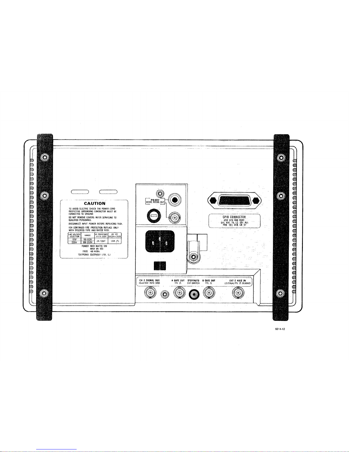
5-7 Rear panel controls and connectors 5-28
5-8 DMM controls and connectors 5-32
6-1 Dimensional drawing 6-39
VI
2465B/2455B/2445B Operators
Page 13
Contents
Tables
Table Page
1-1 Power Cord and Voltage Data 1-2
2-1 Resolution Selections 2-26
2-2 Auto Resolution 2-26
2-3 Delay-by-Events Combinations 2-29
2-4 Sweep Triggering 2-33
6-1 2465A/2455A/2445A Electrical Characteristics 6-2
6-2 Option 01 (DMM) Electrical Characteristics 6-19
6-3 Option 05 (TV) Electrical Characteristics 6-26
6-4 Option 06 (C/T/T) Electrical Characteristics 6-29
6-5 Option 09 (WR) Electrical Characteristics 6-35
6-6 Option 10 (GPIB) Electrical Characteristics 6-37
6-7 Mechanical Characteristics 6-38
6-8 Environmental Requirements 6-40
C-1 Confidence Test Numbers and Affected Functions C-2
2465B/2455B/2445B Operators vii
Page 14

Operators Safety Summary
Operators Safety
Summary
The general
safety
information
in this part of
the summary
is for both
operating
and servicing personnel. Specific warnings and cautions will be found
throughout the manual where they apply
and do not
appear
in this
summary.
Terms
In This Manual
CAUTION statements identify conditions or practices that could result in
damage to the equipment or other property.
WARNING statements identify conditions or practices that could result in
personal injury or loss of life.
As Marked on Equipment
CAUTION indicates a personal injury hazard not immediately accessible as one
reads the markings, or a hazard to property, including the equipment
itself.
DANGER indicates a personal injury hazard immediately accessible as one
reads the marking.
Symbols
In This Manual
A
This symbol indicates where applicable cautionary or other
information is to be found. For maximum input voltage see Table 6-1.
As Marked on Equipment
ff DANGER—High voltage.
A
Protective ground (earth) terminal.
ATTENTION—Refer to manual.
vin
2465B/2455B/2445B Operators
Page 15
Operators Safety Summary
Power Source
This product is intended to operate from a power source that does not apply more
than 250 volts rms between the supply conductors or between either supply
conductor and ground. A protective ground connection by way of the grounding
conductor in the power cord is essential for safe operation.
Grounding
the
Product
This product is grounded through the grounding conductor of the power
cord.
To
avoid electrical shock, plug the power cord into a properly wired receptacle before
connecting to the product input or output terminals. A protective ground
connection by way of the grounding conductor in the power cord is essential for
safe operation.
Danger Arising From Loss
of
Ground
Upon loss of the protective-ground connection, all accessible conductive parts
(including knobs and controls that may appear to be insulating) can render an
electric shock.
Use the
Proper Power Cord
Use only the power cord and connector specified for your product.
Use only a power cord that is in good condition.
For detailed information on power cords and connectors see Table 1-1.
Use the
Proper Fuse
To avoid fire hazard, use only a fuse of the correct type, voltage rating and current
rating as specified in the parts list for your product.
Do Not
Operate
in
Explosive Atmospheres
To avoid explosion, do not operate this product in an explosive atmosphere unless
it has been specifically certified for such operation.
Do Not
Remove Covers
or
Panels
To avoid personal injury, do not remove the product covers or panels. Do not
operate the product without the covers and panels properly installed.
2465B/2455B/2445B Operators
IX
Page 16

HIGH
,jji*;'
,
FtAhGC
41HQ'"' UJ>" tfflWS
DCV
ACV
IIBV
com Hin
WIN.MAX REF
HOU)
mspiAY nisi'LAY
;
/d/'p
'□
.
D a a a a a a ana
>!
" OCA ACA
dllm lOfi
"I
SMOQ1H
MIN MAX
flEF
/,----■.
r% Mn
A
rh
Tektronix 2465B4OOMHZ *?0Z»ltl%»
j-
INTENSITY FOCUS READOUT INTENSITY SCALI: ILLUM
i'iS
POWER*■■■'■■;
MAM IflACf
QFf | flN \
(IND
,,
FK11AIK1N
, ,, v ASIir,
_ i __^ fa \
\t--~r
x^-
-^y
SCALI
\i-^y
btnu — \I-JS t \^LS
rife
*
^■"^
-v-*- mr.rnns ^^ lAtinR.s "^ ? ^~ kw :
SETUP
VERTICAL
TRIGGER
t-'
J
a
ice
7*fK\
STEP/
^..POSITION ^.POSITION | ^POSITION..' XIO iHOLDOFF
„.-;.,„
LEVEL
WHO !H
,tfLV
A
/dfx
- /fK MAG
a ii
o o *
SAVF 4 MODE ~" ^ |
□
if
CM I CH } Cll J CH 4 i| AV At
IRAtK/
*
I
^ 3 4 '!. I/At
imufp
j A/B
IRIG iJIMPr INIlfalEM
-5i;i.
a a u a
!- "a
a' n ii a a D
a
i ■ A111!
I t V i vtlU
III
KE1 p :} . ADD mum-
I:IIIII'/ . IIMM.
] f , AHFF(llini.V
PUS
A
MEASURE.'.
All
HWIIM
I ' *': ,„„ ^^_ » ^
LINE
/i^tt if .
"
UIIM
iH
' ■■ "'
......
' l\ yi * : ~'M '■'<!
t-H j >t
IIEIP
i, ... e ; a
Ql
a a a a
;; f
»c
s pini
INIIIN IUHN
AII
IMISH
B
VOLTS/DIV VOLTS/DIVf A«r SfcC/DIV
hUN/,n
UNI
IINIS
HI) i mr
iv
inn,
AUIV
fin i
""
MODE SOURCE COUPLING
|FASI
|
Q
O
ni;,|i liUHI YALANU rvUAMl":
.- lo V
■ • (fflAi: i i.rtJOiv
O
S
. AC -. . I
RACE
f;Nn
( \ .
J..SEP j ,-..POSITION VOLTS/DIV -^POSITION
«„v <
IMfi
111". -&f ' /F\\ />' IIV\ I 1 i I 1
f.'\V-\
&)
»>
f-1 O < t J
□ : □ t J
ID,.0,0
VOLTS/DIV
, i'f
IW/.IV bV/.IV
j\
o
CH
1onQ
IM.fi l5pF<it(IOV|ik
CH
2
IM!1
l!)|il
5'intlV|ik
CH
3
CA|il
b
^,
AMT
H
?R CH
4
IMfi lf.|)f 54(IOV|ik COMPPnOHKallmi
IMS"! IS||F
54nf>V|ik
iini
(czn)
INH
1
:IWI>
'ifl!;
6860-11
Page 17
CAUTION
TO AVOID ELECTRIC SHOCk
THE
POWER CORD
PROTECTIVE GROUNDING CONDUCTOR MUST
8E
CONNECTED
TO
GROUND
00
NOT
REMOVE COVERS. RtfER SERVICING
TO
QUALIFIED PERSONNEL.
DISCONNECT INPUT POWER DtfORE REPLACING fUSfc.
KIR CONTINUED TIRi PROTECTION REPLACE, ONLY
WITH SPECIFIED TYPE
ANO
RAT
Ell FUSE.
UNE VOUAGE
SELECTION
1ISV
230V
RAN6E
90132V
180 250V
dl I98.GI3AC)
.i X Hi 25UV
■2A fASl
IECI2>
5X?(Jmn1?50V
I.6A (T)
POWER
MAX
WATTS
120
MAX VA
180
FREO.
46
440H;
TEKTRONIX GUERNSEY
LID, L,l
W_-
GP1B CONNECTOR
4EEE
STD 468
PORT
SHV.
AH1.
T6, 13. SRI. RL1.
PPf).'
OGl.
DTjl,
C0. El
^^^
CH Z SIGNAL
OUT
lOmV/OIV INTO 5Qfi
A GATE
OUT
STEP/AUTO 8 GATE
OUT
TtL
Jt {XT
SWITCH
TTL TV.
EXT Z AXIS
.IN
15-25'Vpkl TTL
Jl
BLANKS
~\£
Page 18
||Ejifri~f~li~|ry ilkiiuiwn inrvnmni ivrri
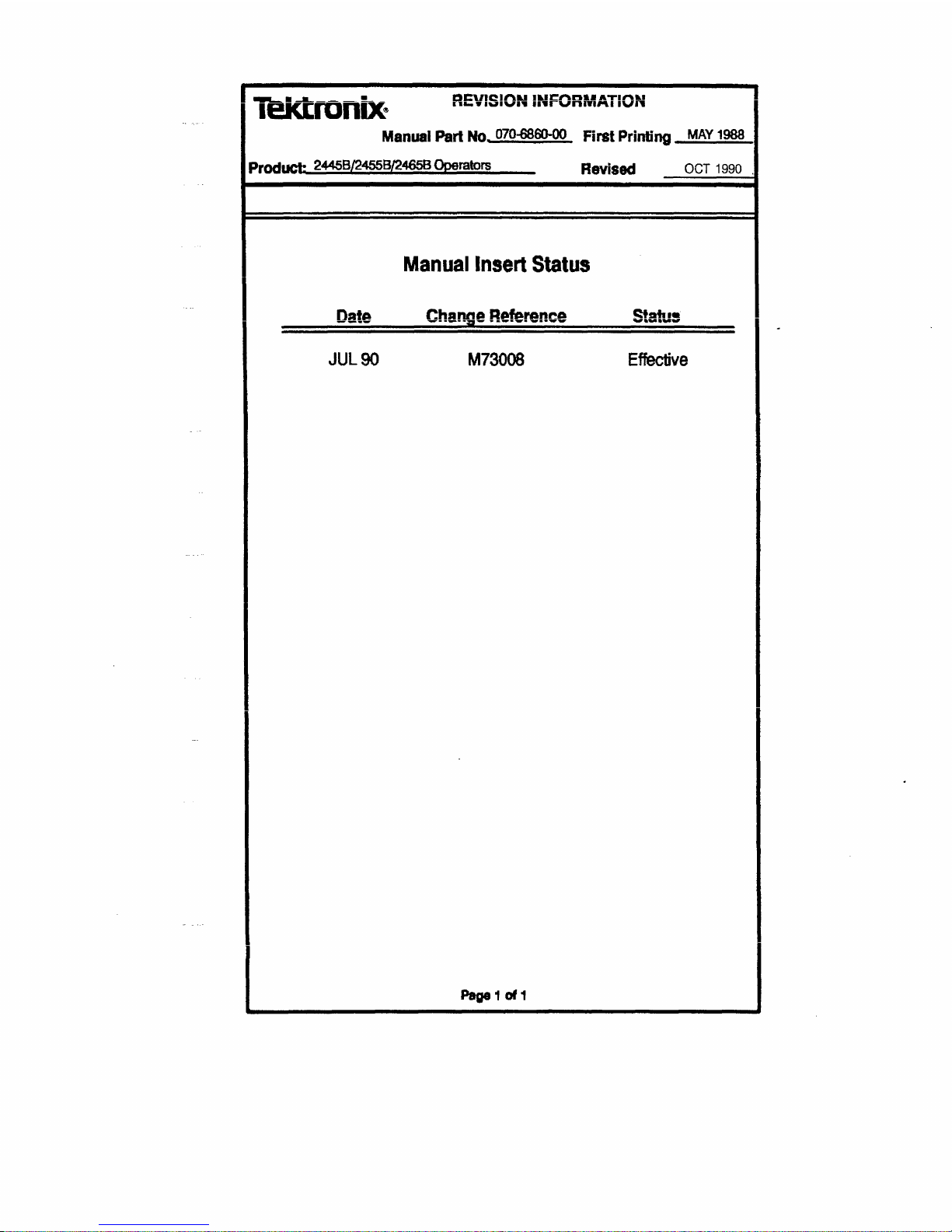
Manual Part No. 070-6860-00 First Printing MAY 1988
Prnrinct- 2445B/2455B/2465B Operators Revised OCT 1990
Manual Insert Status
Date Change Refersnc© Ststu
JUL90 M73008 Effective
r «M »%• W
Pagel of 1
Page 19
•
* * K •■ ■ « »
MANUAL UMANUt INhUHMAI
IUN
COLMTTED
TO
BCH1EN3E
leKtronix
Date:
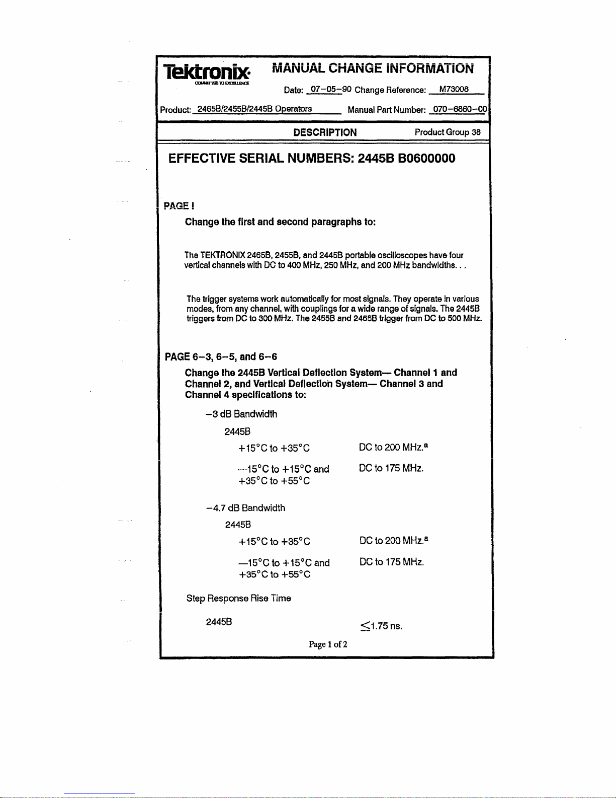
07-05-90 Change Reference: M73006
Product: 2465B/2455B/2445B Operators Manual Part Number: 070-6860-00
DESCRIPTION Product Group 38
EFFECTIVE SERIAL NUMBERS: 2445B B0600000
PAGE!
Change the first and second paragraphs to:
The TEKTRONIX
2465B, 2455B,
and 2445B portable oscilloscopes have four
vertical channels with DC to 400
MHz,
250
MHz,
and 200 MHz bandwldths...
The trigger systems work automatically for most
signals.
They operate
In
various
modes,
from any
channel,
with couplings for a wide range of
signals.
The 2445B
triggers from
DC
to 300
MHz.
The 2455B and 2465B trigger
from
DC to 500 MHz.
PAGE
6-3,6-5,
and 6-6
Change the 2445B Vertical Deflection System— Channel 1 and
Channel 2, and Vertical Deflection System— Channel 3 and
Channel 4 specifications to:
-3 dB Bandwidth
2445B
+ 15°Cto+35°C DC to 200 MHz.
a
—15°C to +15°C and DC to 175 MHz.
+35°Cto+55°C
-4.7 dB Bandwidth
2445B
+15°Cto+35°C DC to 200 MHz.
a
—15°C to +15°C and DC to 175 MHz.
+35°C to +55°C
Step Response Rise Time
2445B
Page 1 of
2
<1.75ns.
Page 20
Product: 2465B/2455B/2445B Oper Date: JJZ=G5=:9Ghange
Reference:
M73QQ9
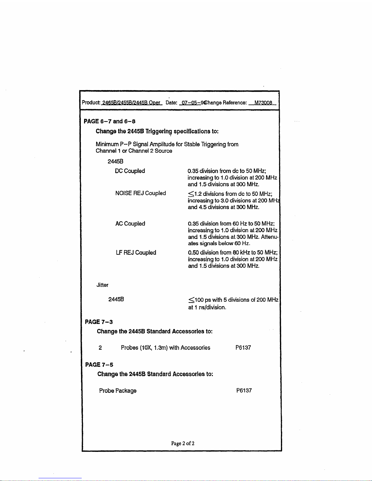
PAGE 6-7 and 6-8
Change the 2445B Triggering specifications to:
Minimum P-P Signal Amplitude for Stable Triggering from
Channel 1 or
Channel
2 Source
2445B
DC
Coupled
NOISE REJ Coupled
AC
Coupled
LF REJ
Coupled
Jitter
2445B
0.35 division from dc to 50 MHz;
increasing to 1.0 division at 200 MHz
and 1.5 divisions at 300 MHz.
<1.2 divisions from dc to
50
MHz;
increasing to 3.0 divisions at 200 MHz
and 4.5 divisions at
300
MHz.
0.35 division from 60 Hz to
50
MHz;
increasing to 1.0 division
at 200
MHz
and 1.5 divisions at
300
MHz.
Attenu-
ates signals below
60
Hz.
0.50 division from 80 kHz to
50
MHz;
increasing to 1.0 division at 200 MHz
and 1.5 divisions at 300 MHz.
<100 ps with 5 divisions of 200 MHz
at 1 ns/division.
PAGE 7-3
Change the 2445B Standard Accessories to:
2 Probes (1 OX, 1,3m) with Accessories
PAGE 7-5
Change the 2445B Standard Accessories to:
Probe Package
P6137
P6137
Page 2 of
2
Page 21

1
General Information
Page 22
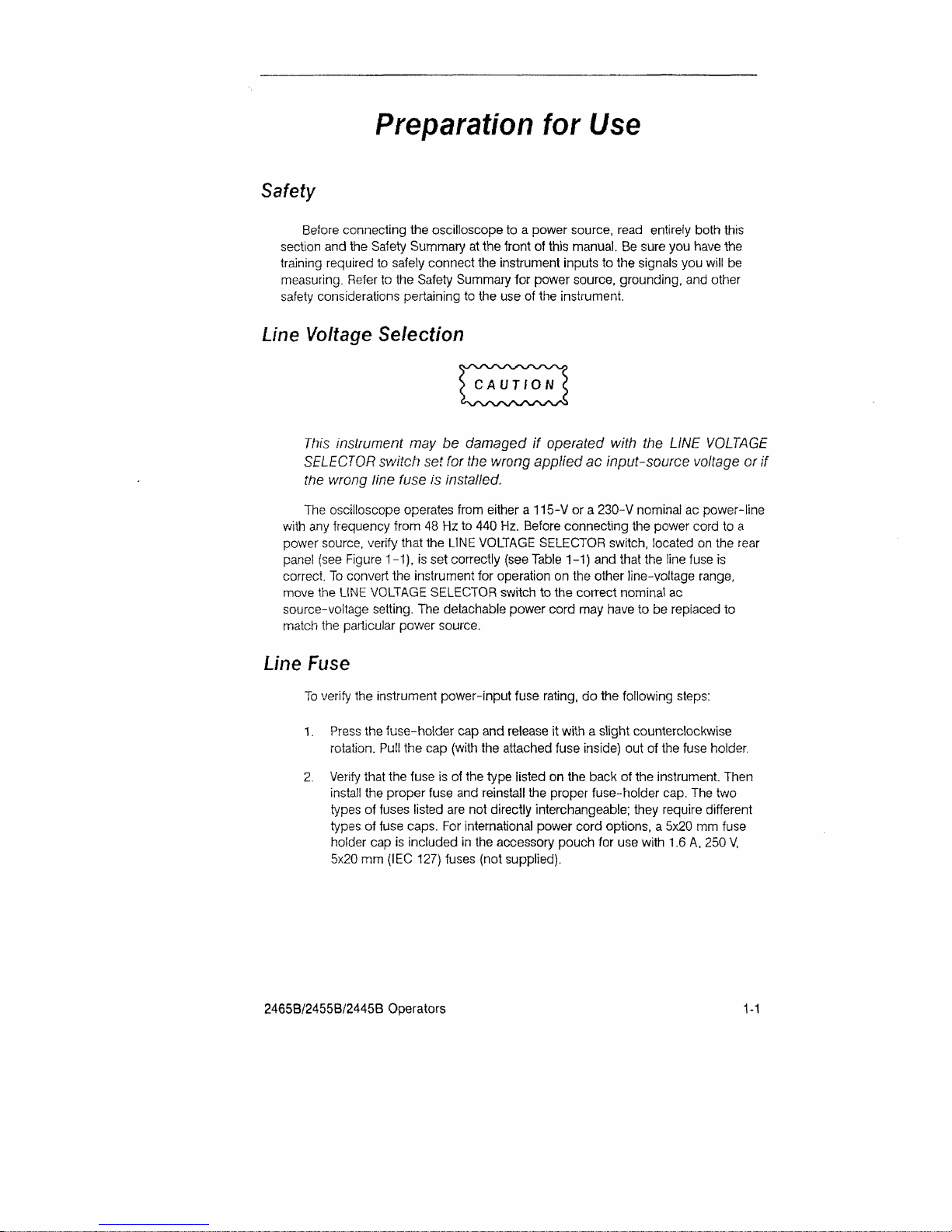
Preparation
for
Use
Safety
Before connecting the oscilloscope to a power source, read entirely both this
section and the Safety Summary at the front of this manual. Be sure you have the
training required to safely connect the instrument inputs to the signals you will be
measuring. Refer to the Safety Summary for power source, grounding, and other
safety considerations pertaining to the use of the instrument.
Line
Voltage
Selection
This instrument may be damaged if operated with the LINE VOLTAGE
SELECTOR switch set for the wrong applied ac input-source voltage or if
the vsrong tine fuse is installed.
The oscilloscope operates from either a 115-V or a 230-V nominal ac power-line
with any frequency from 48 Hz to 440 Hz. Before connecting the power cord to a
power source, verify that the LINE VOLTAGE SELECTOR switch, located on the rear
panel (see Figure 1 -1), is set correctly (see Table 1-1) and that the line fuse is
correct. To convert the instrument for operation on the other line-voltage range,
move the LINE VOLTAGE SELECTOR switch to the correct nominal ac
source-voltage setting. The detachable power cord may have to be replaced to
match the particular power source.
Line Fuse
To verify the instrument power-input fuse rating, do the following steps:
1.
Press the fuse-holder cap and release it with a slight counterclockwise
rotation.
Pull the cap (with the attached fuse inside) out of the fuse holder.
2.
Verify that the fuse is of the type listed on the back of the instrument. Then
install the proper fuse and reinstall the proper fuse-holder cap. The two
types of fuses listed are not directly interchangeable; they require different
types of fuse caps. For international power cord options, a 5x20 mm fuse
holder cap is included in the accessory pouch for use with 1.6 A, 250 V,
5x20 mm (IEC 127) fuses (not supplied).
2465B/2455B/2445B Operators
1-1
Page 23
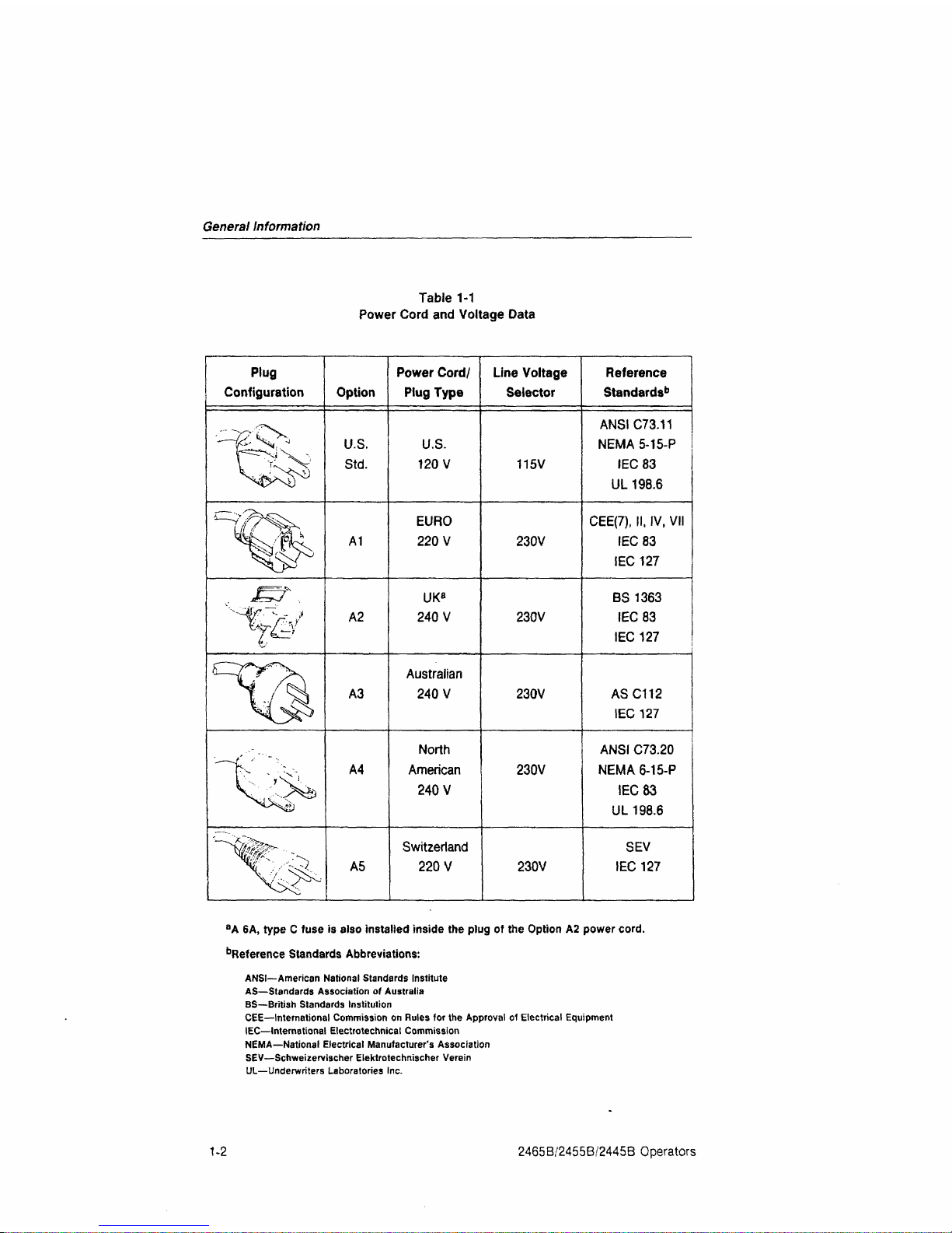
General Information
Table 1-1
Power Cord and Voltage Data
Plug
Configuration
t&
"%
"^
Option
U.S.
Std.
A1
A2
A3
A4
A5
Power Cord/
Plug Type
U.S.
120 V
EURO
220 V
UK
a
240 V
Australian
240 V
North
American
240 V
Switzerland
220 V
Line Voltage
Selector
115V
230V
230V
230V
230V
230V
Reference
Standards'
1
ANSIC73.11
NEMA
5-15-P
IEC83
UL 198.6
CEE(7), II, IV, VII
IEC83
IEC 127
BS 1363
IEC 83
IEC 127
ASC112
IEC 127
ANSI C73.20
NEMA
6-15-P
IEC 83
UL 198.6
SEV
IEC 127
a
A 6A, type C fuse is also installed inside the plug of the Option A2 power
cord.
Reference Standards Abbreviations:
ANSI—American National Standards Institute
AS—Standards Association of Australia
BS—British Standards Institution
CEE—International Commission on Rules for the Approval of Electrical Equipment
IEC—International Electrotechnical Commission
NEMA—National Electrical Manufacturer's Association
SEV—Schweiiervischer Elektrotecfmischer Verein
UL—Underwriters Laboratories Inc.
1-2 2465B/2455B/2445B Operators
Page 24
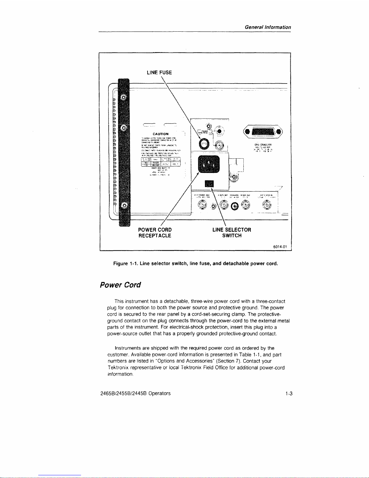
General Information
Figure 1-1. Line selector switch, line fuse, and detachable power cord.
Power
Cord
This instrument has a detachable, three-wire power cord with a three-contact
plug for connection to both the power source and protective ground. The power
cord is secured to the rear panel by a cord-set-securing clamp. The protective-
ground contact on the plug connects through the power-cord to the external metal
parts of the instrument. For electrical-shock protection, insert this plug into a
power-source outlet that has a properly grounded protective-ground contact.
Instruments are shipped with the required power cord as ordered by the
customer. Available power-cord information is presented in Table 1-1, and part
numbers are listed in "Options and Accessories" (Section 7). Contact your
Tektronix representative or iocai Tektronix Fieid Office for additional power-cord
information.
2465B/2455B/2445B Operators
1-3
Page 25
General Information
Instrument Cooling
To prevent instrument damage from internally generated heat, adequate air flow
must be maintained. Before turning on the power, verify that the spaces around the
air-intake holes on the bottom of the cabinet and the fan-exhaust holes in the rear
panel are free of any obstruction to airflow.
Start-up
The oscilloscope automatically performs a set of diagnostic tests each time the
instrument is turned on. These tests warn the user of any available indication that
the instrument may not be fully functional. The tests run for several seconds after
power is applied. If no faults are encountered, the instrument operates normally. A
failure of any of the power-up tests will be indicated by either a flashing TRIG'D
indicator on the instrument front panel or a bottom-line readout on the CRT in the
form:
TEST XX FAIL YY (where XX is the test number and YY is the failure code
of the failed test).
If a failure of any power-up test occurs, the instrument may still be usable for
some applications. To operate the instrument after a power-up test failure, press
the A/B TRIG button. Even if the instrument then functions for your particular
measurement requirement, it should be repaired by a qualified service technician at
the earliest convenience. Additional information on the power-up tests may be
found in Appendix C at the rear of this manual. Consult your service department,
your local Tektronix Service Center, or nearest Tektronix representative if
additional assistance is needed.
1-4
2465B/2455B/2445B Operators
Page 26
General Information
Repackaging
For
Shipment
If this instrument is to be shipped by commercial transportation, it should be
packaged in the original manner. The carton and packaging material in which your
instrument was shipped to you should be retained for this purpose.
If the original packaging is unfit for use or is not available, repackage the
instrument as follows:
1.
Obtain a corrugated cardboard shipping carton having inside dimensions at
least six inches greater than the instrument dimensions and having a carton
test strength of at least 275 pounds.
2.
If the instrument is to be shipped to a Tektronix Service Center for service or
repair, attach a tag to the instrument showing the following: owner of the
instrument (with address), the name of a person at your firm who can be
contacted,
complete instrument type and serial number, and a description of
the service required.
3. Wrap the instrument with polyethylene sheeting or equivalent to protect the
outside finish and prevent entry of packing materials into the instrument.
4.
Cushion the instrument on all sides by tightly packing dunnage or urethane
foam between the carton and the instrument, allowing three inches on each
side.
5. Seal the carton with shipping tape or with an industrial stapler.
6. Mark the address of the Tektronix Service Center and your return address on
the carton in one or more prominent locations.
2465B/2455B/2445B Operators
1-5
Page 27

2
Operation
Page 28
Operation
Operation
Fundamentals
Like any oscilloscope, this instrument draws a graph of voltage as a function of
time.
The VERTICAL controls, marked off by a heavy gray line, define the voltage axis
of the display. SEC/DIV, XI0 MAG, and horizontal POSITION control the time axis of
the display. The TRIGGER controls, marked off by a green box, define the signals
required to initiate sweeps across the time axis. The controls under the CRT affect the
display but not the waveform.
Parametric Measurements
The Parametric Measurement function provided in the instrument gives quick
access to the parameters of your input signal.
To obtain a parametric measurement, simply press the MEASURE button and
select the desired function from the displayed menu. The function is selected by
pressing the button in the VERTICAL MODE area that occupies the same relative
position as the desired menu selection. The measurement function will
automatically scale the input signal before making the measurement.
Parametric measurements require repetitive signals for reliable results.
Measurements on non-repetitive signals will produce unpredictable results.
Repetitive signals that have periodic bursts of signal transitions will also produce
unpredictable results.
Parametric measurements can only be performed on signals in CH 1 or CH 2.
An error message will be displayed if CH 3, CH 4, or ADD are selected for
parametric measurements.
2465B/2455B/2445B Operators
REV NOV 1988
2-1
Page 29
Operation
Getting a Display
1.
Connect a probe from the input of a Vertical channel to a signal.
2.
Select the channel using the Vertical MODE buttons. You may select any
combination of vertical channels. (If you are using the standard accessory
probes, make sure the CH 1 and CH 2 input are not set at 50 IX)
3. Press AUTO Setup to initialize vertical, horizontal, trigger, and display intensity
for a usable display. (If STEP is illuminated, first push RECALL to extinguish it.)
4.
If the resulting display isn't exactly what you want, adjust the appropriate
VOLTS/DIV, SEC/DIV, POSITION, or Trigger controls.
Characteristics of AUTO Setup
With one channel. Auto Setup centers the 0-volt level and makes the vertical
display as large as possible, within the graticule. With more than one channel, the
0-volt levels of CH 1. CH 2, CH 3. and CH 4 are set at +2. 0. -2, and -3 divisions
from center, respectively. When ADD is displayed, the 0-volt level of CH 2 is set at
-2 divisions.
AUTO sets Sec/Div within the range from 20 ns to 2 ms, to show two to five
cycles of most signals. With narrow, low repetition-rate pulses, the sweep runs faster
to stretch out the display, with the appropriate trigger slope.
AUTO Setup sets the trigger for Auto Lvl Mode, Vert Source, DC Coupling, and
Min Holdoff, with level at the midpoint between signal peaks.
The STEP/AUTO EXT SWITCH connector on the rear panel produces the same
functions as the STEP/AUTO button, in response to a switch closure or TTL-low
signal.
The following function is available for instruments with serial numbers
B049999 and below with firmware version 11 and above or for instruments with
serial numbers B050000 and above with firmware version 2 and above (see
Appendix A - EXER04 to determine firmware version). AUTO Setup can also be
activated by pressing any probe ID button if configured to perform an AUTO Setup
using the PROBE Configure menu. The operator can configure the probe ID to
perform one of four possible outcomes (IDENT, AUTO Setup. INIT@50%, or STEP).
Once configured, the instrument will maintain the selection until modified again by
the operator.
The following function is available for instruments with serial numbers
B049999 and below with firmware version 10 and below or for instruments with
serial numbers B050000 and above with firmware version 1 and below (see
Appendix A - EXER04 to determine firmware version). AUTO Setup can also be
activated by pressing any probe ID button twice in 0.5 second.
See "Save and Recall Operation" for the sequence function of Step/Auto.
2-2 2465B/2455B/2445B Operators
Page 30
Operation
Assigning Parametric Measurements to the Auto Setup Function
Any of the Parametric Measurements can be assigned to the Auto Setup
function.
When Auto Setup is activated, the assigned function is performed as
well as the Auto Setup.
To assign a function to Auto Setup:
i. Push MEASURE.
2.
If the CTT is present, select MORE from the menu. Otherwise go to
Step 3.
NOTE
To
select items from a menu, simply press the vertical mode button that
has the same position as the desired item in the menu.
3. Select CONFIGURE from the menu.
4.
Select
AUTO
from the menu.
5. Select the function to be performed with each Auto Setup by pushing
the appropriate MODE button.
Activating AUTO Setup from the Probe
The following function is available for instruments with serial numbers
B049999 and below with firmware version 11 and above or for instruments
with serial numbers B050000 and above with firmware version 2 and above
(see Appendix A - EXER04 to determine firmware version). Pressing the probe
identification button on any Tektronix, Inc. probe will shift the associated trace and
replace the associated scale factor with ID, if IDENT has been selected from the
PROBE CONFIGURE menu.
AUTO Setup, INIT@50% or STEP can also be assigned to the probe ID
function.
To assign a function to probe ID:
1.
Push MEASURE
2.
If CTT is present, select MORE from the menu. Otherwise, go to
Step 3.
2465B/2455B/2445B Operators
2-3
Page 31

Operation
NOTE
To select items from a
menu,
simply
press the vertical mode button that
has the same position
as
the
desired
item
in the menu.
3. Select CONFIGURE from the menu.
4.
Select PROBE from the menu.
5. Finally, select the function to be performed with each probe ID by
pressing the appropriate MODE button. If
AUTO
Setup function is
selected,
any measurement assigned to the AUTO Setup is also
performed.
The following function is available for instruments with serial numbers
B049999 and below with firmware version 10 and below or for instruments
with serial numbers B050000 and above with firmware version 1 and below
(see Appendix A - EXER04 to determine firmware version). Pressing the probe
identification button on any Tek probe will shift the associated trace and replace
the associated scale factor with ID. If the probe identification is pressed twice in
0.5 second, the Auto Setup function is activated. Any measurement assigned to
the Auto Setup function is also performed.
Vertical
For voltage measurements, set VOLTS/DIV
VAR
fully clockwise. For best accuracy,
set VOLTS/DIV for the largest display possible.
Input Coupling
Use 1 MH DC input mode for most applications. This mode is compatible
with the standard accessory, high-impedance probes and it displays logic levels
and dc levels of static signals. Use the pair of buttons near the CH 1 and CH 2
inputs to select input coupling. CH 3 and CH 4 inputs are fixed at 1 MH DC.
GND input mode shows where the
0-volt
level will be displayed with
DC coupling.
Use AC coupling for the special cases where you need to see small signals
on large dc voltages.
Use the 50 Q DC input mode for the best possible vertical performance with
active probes,
50-D,
signal sources, and low-impedance passive probes. A
low-impedance probe can present less than 2 pF load to the signal-source, in
parallel with 500 Cl or 5000 fi with 10X or 100X attenuation.
2-4
2465B/2455B/2445B Operators
Page 32

Operation
Input Conditioning for Video Signals
Video signals can be distorted by ac coupling or by low-frequency
interference. The available Television/Video
(TV)
enhancement adds a TV CLAMP
to the CH 2 input to eliminate such distortion.
To use the TV clamp:
1.
Apply a composite video signal to CH 2.
2.
Select CH 2 Trigger Source and set SLOPE to the displayed polarity of
ihe sync pulses.
3. Set the CH 2 input to TV CLAMP by pressing the upper
input-coupiing button for CH 2 until the readout shows "TVC". The
"back porch" of the video signal will be locked to a fixed level.
Keep the TV Clamp turned off when the trigger source is not composite video
or composite sync, to preserve normal operation of Channel 2. Leave the
rear-panel CH 2 SIGNAL OUT unloaded to avoid a minor distortion in the video
signal when TV Clamp is on.
Channel Selection
Using the Vertical MODE buttons, you can display any combination of the four
vertical channels. To manually switch between CH 1 and another channel, with
minimum button pushing, deselect CH 1 and press the button for the other
channel to turn it on and off; CH 1 is displayed when all other verticals are off.
ADD and
INVERT
Press ADD to display the algebraic sum of CH 1 and CH 2. Select INVERT to
change the sense of the CH 2 waveform or to see the difference between CH 1
and CH 2 on the ADD trace. If you use ADD, the CH 1 and CH 2 VOLTS/DIV
settings should be equal. Parametric measurements will not work if ADD
is selected.
Choosing CHOP or
ALT
With two or more channels, the display is time-shared. Chop mode displays
each channel for a short time and multiplexes during the sweep to give the
appearance of displaying all channels at once. Chop works better than Alt for
sweeps slower than 1 ms/division and for low repetition-rate signals that make the
display flicker, up to 2 jus/division.
Alt mode displays each channel for the duration of a complete sweep. Alt
gives a "cleaner" display of multiple channels than Chop does and is usually
preferred at moderate to high sweep speeds.
20 MHz BW Limit
This mode can give you a sharper trace by eliminating high-frequency
interference. Before using it, check to make sure it doesn't distort the waveform.
2465B/2455B/2445B Operators
2-5
Page 33

Operation
Horizontal
The A Sweep is the only horizontal function you need for most applications. The
A SWP indicator is on when the A-Sweep is displayed. To make sure the A-Sweep is
displayed,
press AUTO Setup and push SEC/DIV in. You can also restore the
A-Sweep display by pushing the SEC/DIV knob in and turning it counterclockwise until
the A SWP indicator lights. If both A SWP and B SWP indicators are off, push
SEC/DIV in and turn it clockwise to escape the X/Y display mode.
The X10 MAGnifier expands the center of the unmagnified waveform.
For best measurement accuracy, set SEC/DIV for the fastest sweep that will
display the interval of interest and set VAR fully clockwise.
See "Delayed Sweep Operation" for more information about B Sweep, B Trigger,
and trace separation.
Trigger Controls
For "hands-off triggering with most signals, select Auto Lvl Mode, Vert Source,
DC Coupling, and MINimum Holdoff.
Auto Lvl mode, with LEVEL in the center half of its range, sets the trigger point
near the midpoint between signal peaks. When LEVEL is set to the - or
■+
end of its
range,
this mode initiates triggering near the 10% or 90% point between signal peaks.
You can select a level anywhere in about the middle 80% of the signal amplitude.
Once set, the level doesn't change unless the signal ceases to trigger the sweep. The
sweep free-runs without a trigger
signal.
With signals below 50 Hz, AUTO LVL may
not find the correct level. If the signal is below 50 Hz but greater than 10 Hz, you can
change the minimum frequency at which Auto Level will work by using the MINFREQ
entry under the measurement CONFIGURE menu. See "Frequency Limit for Auto
Level or Parametric Measurements" for more information.
With Auto Lvl mode and Vert Source, the displayed channel or the first one of a
multichannel display supplies the trigger signal.
Auto mode maintains the trigger level setting and the sweep free-runs if the signal
doesn't meet the triggering requirements.
2-6
2465B/2455B/2445B Operators
Page 34

Operation
Use Auto for monitoring logic signals. Set the LEVEL control to the mean threshold
of the logic system, +1.4 V for TTL. The sweep then triggers on valid transitions and
free-runs to show static highs and lows.
Normal mode produces a sweep only when the trigger signal meets the Level and
Slope criteria.
Use Normal mode for infrequent events and erratic signals.
Sgl Seq mode accepts one trigger for each sweep in the display. Press the lower
Mode button to arm the trigger and illuminate the READY indicator for each sequence.
With a multi-trace display, a sequence comprises up to sixteen sweeps.
Use Sgl Seq to detect a rare event or to eliminate all but the first one of a chaotic
burst of pulses. Set the trigger for the signal of interest in Normal mode. Then press
the lower Mode button to select Sgl Seq and illuminate the READY indicator. To
detect the occurrence of a rare event, display a single trace and arm Sgl Seq with the
trigger set for the event. Periodically check to see if READY is on. If a burst of trigger
events occurs, the sweep runs once for each trace displayed and READY
extinguishes.
Trigger Source
Choose a single trigger source to correctly display the timing relationships
among multiple channels. Choose the channel with the lowest-frequency signal
to avoid ambiguous displays.
With Vert trigger source. Auto Lvl trigger mode or Chop vertical mode
automatically selects a single trigger source, the first one of the displayed
channels.
Use a composite A-Trigger source to compare asynchronous signals. To
generate a composite trigger, select Vert trigger source, a trigger mode other
than Auto Lvl, and Alt vertical mode.
Trigger Coupling
For noisy signals or signals with strongly interfering components, Noise
Reject, HF Reject, and LF Reject coupling give added selectivity. AC coupling
continues triggering when the dc level of the signal changes.
2465B/2455B/2445B Operators
2-7
Page 35

Operation
Trigger Slope
Press SLOPE to select the rising ( + ) or falling (-) edge of the signal to
trigger the sweep.
Trigger Level
INIT@50% sets the trigger level near the midpoint between signal peaks, in
any mode. Some signals below 50 Hz may not produce the correct level setting.
LEVEL gives you complete freedom to choose the most appropriate
threshold voltage on a signal to initiate sweeps, in case neither the Auto Lvl
mode nor INIT@50% provides a suitable threshold.
Trigger Holdoff
With irregular signals such as bursts, the Trigger HOLDOFF setting can
improve display stability. Also, if the signal has a fixed pattern of variation from
cycle to cycle, some modes of the signal may be omitted from the display.
Changing the Holdoff setting can force the instrument to display all the modes
of the signal. Normally, HOLDOFF should be set at MIN. If you must use
HOLDOFF to achieve a stable display, parametric measurements will not
function correctly.
2-8
2465B/2455B/2445B Operators
Page 36

Operation
Video Triggering
The available Television/Video
(TV)
enhancement adds TV LINES. FLD1, and FLD2
Coupling to the A-Trigger. See Appendix A to change the line-number format and the
sync polarity automatically selected when you select TV triggering.
To trigger at the video line rate:
1.
Select a composite video signal as the trigger source.
2.
Select LINES coupling.
3. Set SLOPE to the polarity of the sync.
To trigger at a specific video line:
1.
Select a composite video signal as the trigger source.
2.
Select
FLD1.
FLD2, or ALT coupling.
3. Set SLOPE to the polarity of the sync.
4.
Turn FLD LINE # (A) to the desired line number.
When you increment or decrement the line number outside the range of the
selected
field,
the other field is automatically selected.
With ALT field coupling, the line number is referred to the beginning of both fields.
The trigger level can be adjusted to vary the actual sync trigger point. This can be
useful when triggering on noisy video signals. INIT@50% resets the trigger point to
mid-range.
To compare two video signals with the same format that are not perfectly
synchronized, such as from a camera and a VCR or from the input and output of a time
base corrector:
1.
Display the signals on CH 1 and CH 2, with Alt Vertical mode.
2.
Select VERT Trigger Source, and ALT field trigger coupling.
3. The CH 1 display triggers on field 1 and the CH 2 display triggers on field 2.
TV Lines trigger coupling with multiple vertical channels, Alt Vertical mode, and Vert
Trigger source produce unpredictable results.
A "A" symbol with the line number display shows when the A/FLD LINE # control
can change the line number. If AV, At. or 1/At is on, press a trigger Coupling button to
redirect the control to line number selection. Press AV or At to redirect the control to
cursor or delay adjustment. The first push redirects the control. A second push will
change the A function or trigger coupling.
2465B/2455B/2445B Operators
2-9
Page 37

Operation
If you magnify the vertical display beyond the graticule, the trigger may be
degraded.
To avoid trigger overload, use one channel for display and another channel
with an appropriate video signal as the trigger source. A composite sync signal can be
used for the trigger source as well as composite video.
Readout
To aid waveform interpretation, the readout shows scale factors, delta
measurements, delay times, trigger settings, and other information. To display all readout
information, set the READOUT INTENSITY control clockwise from OFF (SCALE
FACTORS ON). See Figure 2-1.
Trigger Readout
The trigger readout shows which trigger (A or B) is affected by the controls
(Mode, Source, Coupling, Slope, Level, and INIT@50%), which channel (1-4) is
supplying the trigger signal, and the voltage at which triggering takes place, with
the following settings:
Trigger Coupling DC or Noise Reject
Trigger Source Any Single Channel
Vertical Input DC or GND
VOLTS/DIV VAR Fully Clockwise.
If the trigger comes from the word recognizer, which is available with the CTT,
the readout shows the defined word.
For instruments with serial numbers B049999 and below with firmware
version 11 and above or for instruments with serial numbers B050000 and
above with firmware version 2 and above (see Appendix A - EXER04 to
determine firmware version), then all AC trigger couplings (HF Reject, LF
Reject, and AC or AC input coupling provide an indication of the trigger level
setting.
The readout in these modes indicates a reference level (not absolute
value) XXXX and is followed by a "V?" to indicate the relative nature of the
readout.
For instruments with serial numbers B049999 and below with firmware
version 10 and below or for instruments with serial numbers B050000 and
above with firmware version 1 and below (see Appendix A - EXER04 to
determine firmware version), the trigger readout works only when trigger
coupling is DC or Noise Reject, when the trigger source is one, dc-coupled,
vertical channel with VOLTS/DIV VAR in its calibrated position.
Readout Intensity
To display nothing but measurements, set the READOUT INTENSITY control
counterclockwise from OFF (SCALE FACTORS OFF). Rotate the control toward
OFF to decrease readout brightness. When the sweep is faster than
50 jis/division, random 2-jis segments of the waveform may be missing. Set the
control near the center of the word "OFF" to eliminate this interference between
the waveform and the readout.
2-10
2465B/2455B/2445B Operators
Page 38

Operation
Scale
Factors
CH 1 and CH 2 scale factors include "mV" or "V" units indicators. A tilde (~)
over the V indicates AC input coupling. A ground symbol in front of the number
indicates Gnd input coupling. A greater-than symbol (>) indicates the
VOLTS/DIV VAR control is not at its clockwise, calibrated position. A plus sign
{ + )
shows that Add, the algebraic sum of CH 1 and CH 2, is displayed. A down
arrow shows that CH 2 is inverted.
TRIGGER TRIGGER
SOURCE LEVEL
[i,
2.
3 OR
4) INDICATOR
TRIGGER
CURRENTLY
UNDER CONTROL
(A
or B)
INVERT
INDICATOR
W
SWEEP
DELAY TIKE
DELTA VOLTAGE
DELTA TIME
i/DELTA
TIME
PARAMETRIC
MEASUREMENTS
{MENUS
AND
HELP
USE
ALL
FOUR
READOUT LINES)
6860-01
Figure
2-1.
Readout display locations.
CH 3 and CH 4 scale factors assume volts/division units.
The A-Sweep and
B-Sweep
time-scale readouts are always calibrated,
combining the effects of SEC/'DIV, VAR, and X10 MAG. If SEC/DIV VAR is not
at its clockwise setting, the time scale factor includes a decimal point.
2465B/2455B/2445B Operators
2-11
Page 39

Operation
Holdoff Indicator
The holdoff indicator, "HO," is displayed when the HOLDOFF control is not
at minimum.
Parametric Measurements
Parametric measurements (rise time, fall time, frequency, etc.) are displayed
on the second and third lines of the readout. Help and menu information can
use all four lines of the readout.
Probe Effects
Probe attenuation effects are included in scale factors, trigger levels, and
delta volts readouts, if you use the standard accessory probes or other
compatible probes. Pressing the identification button on Tektronix probes
replaces the scale factor for the channel with "ID" and shifts the trace.
2-12
2465B/2455B/2445B Operators
Page 40

Operation
Measurements with
Cursors
The controls in the gray box (AV, At, TRACK/INDEP, A REF OR DLY POS, and A)
operate cursors and sweep delays. With the cursors, you can measure voltage, time,
frequency, ratios, and phase. We often refer to the A REF OR DLY POS control as
"A REF" for convenience.
Cursors are more accurate and easier to use than the graticule. They eliminate the
inconvenience and errors of counting and interpolating graticule markings and they
avoid CRT linearity errors.
For best AV accuracy, display the signal on either CH 1 or CH 2 with VOLTS/DIV
set for three to eight divisions of waveform amplitude. For best At and 1/At accuracy,
use the fastest sweep that will include the interval of interest.
Measure
Voltage
1.
Turn on the AV cursors and readout with the AV button.
2.
Align the cursors with points of interest, such as waveform peaks, using
the A REF and A knobs.
3. The readout shows the voltage between the points marked by the
cursors.
4.
Press AV to turn off the AV cursors and readout.
Measure
Time,
with
A-Sweep
or
B-Sweep
Alone (SEC/DIV
in)
1.
Turn on the At cursors and readout with the At button.
2.
Align the cursors with points of interest, such as waveform zero-
crossings, using the A REF and A knobs.
3. The readout shows the time between the points marked by the cursors.
4.
Press At to turn off the At cursors and readout.
2465B/2455B/2445B Operators
2-13
Page 41

Operation
Measure Frequency with Cursors
1.
Turn on the 1/At cursors and readout by pressing the AV and At
buttons together.
2.
Align the cursors with identical points, such as zero crossings, on
adjacent cycles
of the waveform, using the A REF and A knobs.
3. The readout shows the frequency of the signal.
4.
Press AV and At together or press either A button twice to turn off the
1/At cursors and readout.
Measure
Voltage
Ratio,
Time Ratio (such
as
Duty
Factor),
or
Phase
1.
Set VOLTS/DIV or SEC/DIV so a feature of the waveform which you
consider the 100% reference covers more than five divisions of the
graticule.
2.
Turn the VOLTS/DIV VAR or SEC/DIV VAR counterclockwise from the
detent until the 100% reference feature covers exactly five divisions.
You can use one signal as a reference and compare others to it. For
phase,
set one cycle, which is the 360 degree reference, to five
divisions.
3. Press AV to measure voltage ratio, At for time ratio, or AV and At
together for phase. The VAR must be counterclockwise from the detent
position to turn on the RATIO or PHASE readout.
4.
Turn A REF and A to align the cursors with the portion of the waveform
to be compared to the reference portion. Phase is usually a two-channel
measurement between zero crossings. (Be sure zero crossings for
phase measurements are positioned at the graticule center.)
5. The readout shows the ratio or phase shift.
6. Press the same AV or At button, or
both,
to turn off the cursors and
readout.
Choosing Tracking
or
Independent Delta
Mode
Use the INDEP mode for most measurements, with each cursor
independently adjustable. Use TRACK mode, where the A REF knob moves
both cursors as a pair, to compare waveform features. The A control moves
only the A cursor.
2-14
2465B/2455B/2445B Operators
Page 42

Operation
Voltage Measurements
Automatic voltage measurements can be made through the measurement menus.
Set the oscilloscope up for automatic voltage measurement by:
1.
Pressing the MEASURE button.
2.
Selecting VOLTS from the menu by pressing button number 2.
The +
peak,
-peak, average, and peak-to-peak volts are measured and displayed
in the readout.
If the voltage measured has an extremely small peak-to-peak value, only the
average volts will be displayed.
If the input signal is AC coupled, only the peak-to-peak value will be displayed.
The voltage measurement is sensitive to input frequency. Signal frequencies above
1 MHz will have measurement errors greater than 5%.
For accurate voltage measurements using VOLTS, it is important that a DC
balance has been done at a temperature within 5°C of the operating environment
temperature. See "Auto DC Balance Routine" in the "Checks and Adjustments"
section for more information.
Display
Operation
Set both INTENSITY and READOUT INTENSITY controls for comfortable viewing,
but no brighter than you need. Use high intensity settings to observe low repetitionrate signals, narrow pulses in long time intervals, or occasional variations in
fast signals.
2465B/2455B/2445B Operators
2-15
Page 43

Operation
Signal
Connections
A probe is usually the most convenient way to connect an input signal to the
instrument. Shielded to prevent pickup of electromagnetic interference, the standard
10X probes supplied with the instrument present a high impedance to a circuit under
test. While the 10
U9,
and 11 pF of the probe are a negligible load on most circuits,
very fast circuits or very high impedance circuits may be seriously affected.
Waveform Fidelity
and
Probe Grounds
A probe ground must be used for accurate measurements and observations.
Use the shortest ground connection possible if you want good waveform
fidelity.
The standard-accessory probe is a compensated 10X voltage divider. It
appears resistive at low frequencies and capacitive for high-frequency signal
components. The probe input capacitance can interact with the inductance of
either a long signal lead or a long ground lead to form a series-resonant circuit.
This circuit can affect system bandwidth and can ring if driven by a fast step.
Always keep both the ground lead and the probe signal-input connections as
short as possible to maintain the best waveform fidelity.
In some cases, a separate ground from the unit under test to the ground
receptacle on the oscilloscope front panel can reduce interference from lowfrequency hum and noise. For rough checks of larger signals, such as
5-volt
logic, a ground lead separate from the probe or even the safety ground
connection which is shared with the unit under test may work for a signal
ground.
Fast signal transitions will be highly distorted and extraneous noise will
be induced without the probe ground connection.
Probe Compensation
Misadjustment of probe compensation is a common source of measurement
error. Due to variations in oscilloscope input characteristics, probe
compensation should be checked whenever the probe is moved from one
oscilloscope to another or between channels of a multichannel oscilloscope.
See the procedure in the "Checks and Adjustments" section of the manual.
2-16
2465B/2455B/2445B Operators
Page 44

Operation
Probe Handling
Both the probe and the probe accessories should be handled carefully to
prevent damage. Striking a hard surface can damage both the probe body and
the probe tip. Exercise care to prevent the cable from being crushed, kinked, or
excessively strained.
Coaxial Cables
To maintain good waveform fidelity and accuracy, only high-quality, low-loss
coaxial cables should be used. The instrument is optimized for 50 0 sources,
driving the 50
9.
dc input through 50 U cable. If you use another signal source
impedance, such as 75 ft, use the appropriate coaxial cable and an external
terminator to match, with the input set at 1 MQ. Some high frequency response
will be lost with external termination.
Magnify
Waveform
Details
with
Delayed-Sweep
1.
Display a waveform with the A Sweep, then pull SEC/DIV out to activate B
Sweep and light both the A SWP and B SWP indicators (INTEN mode).
2.
If a B-Trigger Mode indicator is on, select RUN AFT DLY. (If an A-Trigger
Mode indicator is on, the B Trigger has been set previously to RUN AFT DLY.)
3. Set A REF OR DLY POS to place the small intensified zone at a point of
interest. (This zone may be more apparent with a lower Intensity setting.) If the
A Sweep terminates just after the intensified zone, you can move the
HOLDOFF control and set it at MIN. (Two intensified zones appear if you have
selected At or 1/At. See " Delta-Delay-Time.")
4.
Turn SEC/DIV clockwise, with the knob pulled out, to expand the point of
interest on the B Sweep, while observing its relationship to everything else on
the A Sweep (ALT mode). Use TRACE SEP to separate the A-Sweep and
B-Sweep traces.
5. If you want to simplify the display and obtain the best possible view of the
magnified details, push the SEC/DIV knob in to display only the B Sweep. If
you want the brightest trace possible, set HOLDOFF to B ENDS A, which
makes the sweep repetition rate as high as possible.
6. Select AV, At, or 1/At when the SEC/DIV knob is pushed in to measure
waveform details with cursors. The A REF and A controls have no effect on
sweep delay while cursors are displayed.
2465B/2455B/2445B Operators
2-17
Page 45

Operation
B-Trigger
Operation
Use the B Trigger to eliminate jitter in B-Sweep displays. With the available
Counter/Timer/Trigger
(CTT),
the B Trigger locks a delay-time or delta-delay-time
measurement to the signal, so any variations are tracked automatically. However,
without the
CTT,
the B Trigger obscures delay or delta-delay measurements and the
readout includes a question mark.
Distinguishing RUN
AFT
DL Y
and
TRIG
AFT
DL Y
With RUN AFT DLY mode, the A REF OR DLY POS and ^ controls adjust
the delay-time or delta-delay-time. The intensified zones on the A-Sweep trace
move continuously as the controls are adjusted. If the B-Trigger mode is TRIG
AFT DLY and a signal triggers the B Sweep, the delay times and intensified
zones jump to successive B-Trigger points as delay time is adjusted. With TRIG
AFT DLY, the actual delay time is controlled by the signal, as enabled by the
A Sweep and the A REF and A settings.
Setting
the B
Trigger
1.
When the B SWP indicator is on, press A/B TRIG to illuminate a
B-Trigger Mode indicator. (If B-Trigger mode is not RUN AFT DLY, a
B-Trigger Mode indicator will be on when the B SWP indicator is on.)
2.
Select TRIG AFT DLY Mode.
3. Set SOURCE, COUPLING, SLOPE, INIT@50%, and LEVEL controls
as required.
Changing
the A
Trigger while B Trigger is
Active
1.
Press and hold A/B TRIG while adjusting SOURCE, COUPLING,
SLOPE,
INIT@50%, and LEVEL controls for the A Trigger.
2.
Alternatively, choose RUN AFT DLY B-Trigger mode and momentarily
press A/B TRIG, then adjust A Trigger. With RUN AFT DLY B-Trigger
mode or SGL SEQ A-Trigger mode (or an active
CTT function
that uses
the B Trigger), the trigger controls alternate between A Trigger and
B Trigger each time A/B TRIG is momentarily pressed.
2-18
2465B/2455B/2445B Operators
Page 46

Operation
Delta-Delay- Time
Use the delayed (B) sweep to magnify both ends of a time interval for the best
measurement accuracy available. Appendix D gives relative accuracies of the various
time-measurement techniques.
Measure
Time
or
Frequency with Delta-Delay-Time
1.
Display the time interval or signal period with the A Sweep running as
fast as possible, unmagnified, up to one speed slower than the fastest
SEC/DIV setting. If the interval is a propagation delay or other twosignal measurement, display the signals on CH 1 and CH 2 and trigger
A Sweep on the earlier of the two.
2.
Pull SEC/DIV out to activate B Sweep and light the A SWP and B SWP
indicators (INTEN mode). (If you inadvertently chose the fastest
A-Sweep speed, the CH2 Delay Match function will be active. See the
"Operator Checks and Adjustments" section.)
3. If a B-Trigger Mode indicator is on, select RUN AFT DLY. (If an
A-Trigger Mode indicator is on, the B-Trigger has been set previously to
RUN AFT DLY.)
4.
Select At or 1/At while the SEC/DIV knob is out.
5. Adjust A REF OR DLY POS and A to place the pair of intensified zones
at the beginning and end of the interval of interest. If the A Sweep
terminates just after the intensified zones, you can move the HOLDOFF
control and set it at MIN.
6. Turn SEC/DIV clockwise with the knob pulled out to magnify the ends
of the interval on the B Sweep while observing the entire interval on the
A Sweep (ALT mode). Use TRACE SEP to separate the A-Sweep and
B-Sweep traces as desired.
7. Set A REF and A to superimpose the magnified displays of the
beginning and end of the interval. The readout shows the interval.
Without the
CTT,
make delta-delay-time measurements only in the RUN AFT
DLY trigger mode, where the B Sweep runs immediately after the set delays. If
the B Sweep is triggered (TRIG AFT DLY), it waits for a trigger after the set
delay, so the actual delay time may differ from the delay or At readout by as
much as twice the signal period.
2465B/2455B/2445B Operators
2-19
Page 47

Operation
Delta-Delay-Time Measurement Characteristics
A delta-delay-time measurement is valid between a pair of points
superimposed on the pair of B Sweeps, regardless of display positions, Trace
Sep setting, and CRT-distortion errors. In other words, the only points that can
be superimposed are those points that are separated by the delta-time value.
(Good accuracy for short intervals does depend on correct CH 2 DLY
adjustment. See "Operator Checks and Adjustments" section.)
The main sweep trigger event begins the interval of interest for many
measurements. The delta-delay-time measurement can include the A-Sweep
trigger event with A SEC/DIV set faster than 50
us.
If an interval begins less
than 0.05 division from the beginning of A Sweep, the readout shows a
question mark. Move A REF clockwise and change the A-Trigger controls as
required to eliminate the question mark and still see a suitable waveform feature
for the beginning of the interval.
Single-Delay-Time
Measurements
For intervals longer than 10
MS
or for low repetition rate signals that make the
display flicker, you may prefer to use the B Sweep without At. Without At, the display
repetition rate is higher and the Dly readout shows the time from the start of A Sweep
to the start of B Sweep. Compared to delta-delay-time measurements, some accuracy
will be lost, unless you can take the difference between one delay time and another.
1.
Display the time interval with the A Sweep running as fast as possible,
unmagnified. If the interval is a propagation delay or other two-signal
measurement, apply the signals to CH 1 and CH 2. For maximum display
repetition rate, display only the channel with the end of the interval. Trigger
the A Sweep at the beginning of the interval. Turn off At or 1/At.
2.
Pull SEC/DIV out to activate B Sweep and light both the A SWP and B SWP
indicators (INTEN mode).
3. If a B-Trigger Mode indicator is on, select RUN AFT DLY. (If an A-Trigger
Mode indicator is on, the B-Trigger has been set previously to RUN AFT DLY.)
4.
Set A REF OR DLY POS to place the intensified zone at the end of the
interval.
5. Turn SEC/DIV clockwise with the knob pulled out to magnify the end of the
interval on the B Sweep while observing its relationship to the beginning of the
interval on the A Sweep (ALT mode). Use TRACE SEP to separate the
A-Sweep and B-Sweep traces.
6. Set A REF OR DLY POS to align the end of the interval with the left end of the
B Sweep. The DLY reading is the length of the interval.
7. If you want to simplify the display and obtain the best possible view of the end
of the interval, push the SEC/DIV knob in when A and B SEC/DIV settings are
unequal to display only the B Sweep.
2-20 2465B/2455B/2445B Operators
Page 48

Operation
Time
Interval
Measurement
The Parametric Measurement feature automatically makes time interval
measurements between any two selected points. To make a time interval
measurement:
1.
Push the MEASURE button.
2.
Select TIME from the displayed menu by pushing button 6 in the Vertical
mode area.
Before making the first measurement using the Time Function, configure the
measurement by:
1.
Pushing the MEASURE button.
2.
If the Crroption is present, select MORE from the menu. Then, select
CONFIGURE from the displayed menu. Otherwise, select CONFIGURE from
the menu.
3. Select TIME from the menu
4.
Using the A REF OR DLY POS and the A controls select the channel, slope.
and level of the start and stop events that define the time interval.
The A REF OR DLY POS control moves the underlining cursor among the various
items.
When an item is underlined, turning the A control will change its value.
Pressing any one of the VERT mode buttons will exit from this menu, leaving the
time-measurement configuration you have defined.
Pressing MEASURE with a measurement menu displayed will display additional
help messages, if available.
To make-a measurement with these configuration values, press MEASURE, then
select TIME from the menu. The configuration values will remain the same until
changed using the above procedure.
2465B/2455B/2445B Operators
2-21
Page 49

Operation
Precision Timing
The available Counter/Timer/Trigger
(CTT)
directly and precisely measures any
interval defined by the delayed (B) Sweep and the
B-Trigger.
The
CTT also
reduces
the effort required for repetitive measurements or measurements on changing signals.
Direct
and
Indirect Measurements
As the counter completes each
direct
measurement, the last character of the
units symbol blinks. If the readout includes the word "SET," it indicates an
indirect
measurement of delay-time, including delta-delay-time or
1/delta-delay-
time.
Indirect measurements are inferred from the A Sweep and control
settings.
Indirect delay-time measurements are displayed when any Count. Delay-by-
Events, or Logic-Trigger function of the C7Tis active, except B Sweep
triggered by the Word Recognizer. Indirect measurements are also displayed for
a few seconds when A REF or A are adjusted. Moving any control that affects
direct measurements produces an indirect reading until a new, direct
measurement is complete.
Direct, counted measurements may be different from indirect {"SET-')
measurements for any of the following reasons:
1.
Direct measurements are more accurate and show more digits of
resolution;
2.
When B Sweep is triggered, both the waveform display and the direct
measurement respond to the signal. Indirect measurements respond
only to control settings, regardless of the signal, and they include a
question mark when B Sweep is triggered;
3. Both direct and indirect measurements in RUN AFT DLY Mode suffer
from offset errors. Direct delay measurements, without At or 1/At, are
accurately calibrated in TRIG AFT DLY Mode, from the A-Trigger event
to the
B-Trigger
event.
Condition Messages
One of the following messages, indicating the described condition, may
appear instead of a measurement:
AVERAGING The selected resolution requires more sweeps.
NO A TRIGGER The A-Trigger event has not occurred.
MISSING B TRIG At least one A Sweep occurred without a
B-Trigger
event during the A Sweep.
NO ATRG VERT SRC Multiple A-Trigger sources are selected.
2-22
2465B/2455B/2445B Operators
Page 50

Operation
Triggered Delta-Delay-Time
Measurements
The available Counter/Timer/Trigger (CTT) directly measures intervals defined by
the B-Sweep delays and B Trigger. B Trigger with At and 1/At can have different
sources, levels, and slopes for the pair of B-sweeps. Repeatedly pressing the lower
Mode button selects the following sequence of B-Trigger modes with the noted
characteristics:
With or without At or 1/At:
RUN AFT DLY
B Sweep runs immediately after the set delay.
Without At or 1/At:
TRIG AFT DLY
B Sweep runs at the first trigger after the set delay.
With At or 1/At:
TRIG AFT DLY and TRIG A DLY {both indicators on)
SLOPE and LEVEL settings for triggering at A REF delay and A delay
are common.
TRIG A DLY
SLOPE and LEVEL for A delay can be set independent of the setting for
A REF deiay.
TRIG AFT DLY
SLOPE and LEVEL for A REF can be set independent of the setting for
A delay.
TRIG A DLY
Repeated operation of the lower Mode button toggles between TRIG
AFT DLY and TRIG A DLY.
With At or 1/At and TRIG AFT DLY or TRIG A DLY, the upper Mode button selects
the TRIG AFT DLY and TRIG A DLY mode, where Siope and Levei are common for
both delays.
2465B/2455B/2445B Operators
2-23
Page 51

Operation
Measure a Time Interval Defined
by the
B-Trigger
1.
Follow the first five steps of the procedure in "Measure Time or
Frequency with Delta-Delay-Time/ earlier in this section.
2.
If the interval is a propagation delay or other two-signal measurement,
select ALT Vertical Mode and be sure A-Trigger Source is a single
channel.
Note that A REF controls the intensified zone on the CH 1
trace.
3. Select TRIG A DLY B-Trigger Mode. For the special case of a
measurement on one signal where the beginning and end of the interval
have the same slope and threshold, select TRIG AFT DLY and TRIG
A DLY (both indicators on).
4.
Set B-Trigger Source to VERT. If the measurement is limited to one
signal and more than one signal is displayed, either deselect the other
signals or set Source to the appropriate channel. If two channels are
used,
only those two channels should be displayed.
5. Set B-Trigger Coupling to DC. For unusual applications, other couplings
may be preferred.
6. Press INIT@50%. If necessary, adjust LEVEL for the desired trigger
threshold.
7. Select TRIG AFT DLY Mode and repeat Step 6. (For the special case
noted in Step 3, skip this step.)
8. If required, readjust A REF and A to intensify the transitions that mark
the beginning and end of the interval. In some cases, A-Trigger or
B-Trigger settings may need to change in order to trigger on the
beginning of the interval.
9. Turn SEC/DIV clockwise to magnify the ends of the interval and
readjust LEVEL as required to superimpose them. (Skip this step if
signal transition times are much shorter than the required accuracy.)
10.
Read the measurement from the readout when "SET" disappears.
2-24
2465B/2455B/2445B Operators
Page 52

Operation
Time
Interval
Resolution
The available Counter/Timer/Trigger
(CTT)
measures Delay-Time, Delta-Delay-Time,
and 1/Delta-Delay-Time, with the delayed sweep. You can choose the optimum time-
interval resolution for these measurements.
1.
Press the MEASURE button.
2.
Select MORE from the menu.
3. Select CONFIGURE from the menu.
4.
Select RESOLUTION from the menu. The presently selected resolution is
indicated by an underline cursor.
5. Select the desired resolution by pushing the appropriate menu (VERTICAL
MODE) button.
Measurement
Updating
AUTO updates the measurement either every 1/2 second or when a measurement
is available, whichever is longer. With 1 ns, 100 ps, and 10 ps resolution, the
measurement is updated after enough sweeps have occurred for a valid average, as
indicated under "N for Average" in Table 2-1.
2465B/2455B/2445B Operators
2-25
Page 53

Operation
Table 2-1
Resolution Selections
A SEC/DIV
10 ns to 500 ms
10 ns to 5 us
10
MS
to 50
n$
100 ^s to 500 ps
1 ms to 5 ms
10 ms to 50 ms
100 ms to 500 ms
Selection
AUTO
10 ps
100 ps
1 ns
10 ps or 100 ps
1 ns
10 ps to 1 ns
Any
Any
Any
Least Digit
See Table 2-2
10 ps
100 ps
1 ns
100 ps
1 ns
1 ns
10 ns
100 ns
1 vS
N for Average
See Table 2-2
> 10
6
> 10
4
> 100
> 10
4
> 100
> 100
> 1
> 1
> 1
Table 2-2
Auto Resolution
A SEC/DIV
10 ns to 2 jus
10 ns to 2 us
5 MS to 200 MS
10 ns to200/iS
500 jiS to 5 ms
10 ms to 50 ms
100 ms to 500 ms
Trigger Rate
> 20 kHz
200 Hz to 20 kHz
> 200 Hz
< 200 Hz
Any
Any
Any
Least Digit
100 ps
1 ns
1 ns
10 ns
10 ns
100 ns
1 MS
N for Average
> 10
4
> 100
> 100
> 1
> 1
> 1
> 1
2-26
2465B/2455B/2445B Operators
Page 54

Operation
Frequency,
Period,
and Totalize
Counting
With Parametric Measurements, the Frequency and Period of the signal on the
lowest numbered channel that is displayed can be measured by:
1.
Pushing the MEASURE button.
2.
Selecting FREQ from the menu.
Frequency and period measurements appear in the second and third lines of
the display.
The source of the A trigger that is counted is shown on the far left of the
second line of the display as CHn: where n can be either 1 or 2.
If the C77
is
present:
1.
Press the MEASURE button.
2.
Select COUNTER from the menu.
3. Select FREQUENCY or PERIOD from the menu.
4.
Frequency or period measurements will be displayed in the upper right
hand corner of the display. Measurements will be updated 3 times per
second or once per period whichever is slower. The input frequency must
be 150 MHz or less.
Totalize Random
or
Low Repetition
Rate
Events
1.
Press the MEASURE button.
2.
Select COUNTER from the menu.
3. Select TOTAL from the menu.
4.
Move any front panel switch to reset the displayed count.
Canceling Menu Functions
To exit from any MEASURE menu, select OFF from the menu or press any
other front panel switch except VERTICAL MODE or MEASURE.
Pressing MEASURE while in a menu cycles HELP text iines through the
bottom line of the readout.
2465B/2455B/2445B Operators
2-27
Page 55

Operation
Frequency Measurement
with
External Reference
(Option
1E)
1.
Connect a precision frequency standard signal (must have an accuracy better
than 10 ppm) to BNC connector EXT REF IN, located on rear panel. The
reference signal must be greater than 2 V peak-to-peak into a 50 Q or 75
Q
load with frequency of 1 MHz, 3.579545 MHz, 4.4336188 MHz, 5 MHz, or
10 MHz.
2.
Select FREQUENCY as described above.
3. After 100 measurements (approximately 1 minute), the frequency readout will
display the applied input signal frequency in 8 digits.
Delay Sweeps by Event
Counts
The Counter/Timer/Trigger (Option 09 or 06) includes delay-by-events for either the
A Sweep or the B Sweep. Event counting begins at a starting event on a vertical
input, defined by the A Trigger. Delay-counting events are defined by the B Trigger. In
addition,
the available Word Recognizer
(WR) can
define either start or delay-counting
events. The combinations available are shown in Table 2-3.
Which
Sweep to
Delay
When the A Sweep is delayed by events, the event count can accumulate
for unlimited time. Then the B Sweep can be delayed by time to magnify
waveform details.
When the B Sweep is delayed by events, the event count must accumulate
during the A Sweep. Then the intensified A Sweep can show the timing
between the start event and the delay count.
2-28 2465B/2455B/2445B Operators
Page 56

Operation
Table 2-3
Delay-by-Events Combinations
Sweep to
Delay
A
B
Start
Ml
A Trigger
A Trigger
Event to
Delay by
B Trigger
B Trigger
Explanation
Delay begins at the A-Trigger event;
then A Sweep runs after the
selected number of
B-Trigger
events.
Delay begins when the A Sweep is
triggered by the A-trigger event;
then B Sweep runs after the
selected number of
B-Trigger
events, if the A Sweep has not
terminated.
Table 2-3 (cont)
Added Delay-by-Events Combinations with the Word Recognizer
A
B
A
A
A Trigger
A Trigger
Word
Recognizer
Word
Recognizer
Word
Recognizer
Word
Recognizer
B Trigger
Word
Recognizer
Delay begins at the A Trigger; then
A Sweep runs after the selected
number of words are recognized.
Dplav hpnin<: whon thp A £u«apn ic
triggered by the A-Trigger event;
then B Sweep runs after the
selected number of words are
recognized, if the A Sweep has not
terminated.
Delay begins when a word is
recognized; then A Sweep runs
after the selected number of BTrigger events.
The A Sweep runs after the selected
number of words are recognized.
2465B/2455B/2445B Operators
2-29
Page 57

Operation
Initiate
a Sweep by an
Event Count (Delay-by-Events)
1.
Press the MEASURE button.
2.
Select MORE from the menu.
3. Select DELAY-BY-EVENTS from the menu. The presently selected delay by
event options are indicated by underline cursors.
4.
The sweep that you wish to delay, either A Sweep (A SWP) or B Sweep (B
SWP), is selected by pressing either VERT MODE button 1 or 5.
The starting event, either the A Trigger (ATR-START) or the Word
Recognizer (WR-START), is selected by pressing VERT MODE button
2 or 6.
The event that is counted for the delay, either the B Trigger events (DLY-
BY-B) or the Word Recognizer event (DLY-BY-WR), is selected by pressing
VERT MODE button 3 or 7.
5. Press VERT MODE button 8 to exit the menu after making your selections.
VERT MODE button 4 (OFF) will turn off the delay-by-events function.
If B Sweep is delayed by events, the message "PULL SEC/DIV" appears until
the B Sweep is activated.
The display shows "A" or "B" to identify the sweep delayed, "DBE" to indicate
the Delay-by-Events function, and the number of events required to initiate the
sweep, for example:
A DBE 1234567
Change
the
Number
of
Events
1.
Turn off any competing function, such as At, so the Delay-by-Events
display appears on the right-hand side of the CRT.
2.
Turn the A REF OR DLY POS knob to underline a digit.
3. Turn the A knob to change the value of the digit.
Reset
the Number
of
Events
to One
1.
Turn the A REF OR DLY POS knob to underline the most significant
digit of the number.
2.
Turn the A knob counterclockwise until all digits are 0 except the
rightmost digit. The smallest value of the rightmost digit is 1.
Decrementing the most significant digit when it is 0 or incrementing a
digit when it and higher order digits are at maximum moves the underline
cursor to the right.
2-30
2465B/2455B/2445B Operators
Page 58

Operation
Avoid Ambiguous Event Counts
With slow signal transitions, the start event detected by the A Trigger may
also be detected as a delaying event by the B Trigger, depending on SLOPE
and LEVEL settings of the two triggers.
When the time between the start event and the first delaying event is less
than 4 ns. the first delaying event may or may not be counted. In most cases,
the ambiguity can be resolved by choosing appropriate trigger slopes for the
start and delaying events.
To see exactly which event is counted as the first event, select
B-Sweep
Delayed-by-Events, pull SEC/DIV out to display the intensified A Sweep, and
set the event count to 1. The intensified zone will show which event is
counted first.
Canceling Menu Functions
To exit from any MEASURE menu, select OFF from the menu or press any
other front panel switch except VERTICAL MODE or MEASURE.
Pressing MEASURE while in a menu cycles HELP text lines through the
bottom line of the readout.
2465B/2455B/2445B Operators
2-31
Page 59

Operation
Logic
Triggering
The available Counter/Timer/Trigger (CTT) enhances trigger selectivity. Sweeps can
be initiated by combinations of two vertical signals, defined by A Trigger and
B Trigger. The available Word Recognizer (WR) expands logic triggering to 17-bit
patterns, either synchronous or asynchronous.
Initiate
a Sweep
with
the
Logic Trigger
1.
Press the MEASURE button.
2.
Select MORE from the menu.
3. Select LOGIC-TRIGGER from the menu.
4.
Select the desired triggering function by pushing the appropriate menu
{VERTICAL MODE) button:
a. A-AND-B — Triggers the A sweep only on the coincidence of the
A trigger event and the B trigger event.
The A and B trigger events are considered to be logically true if the
trigger input signal is more positive than the trigger level and + slope is
selected.
If - slope is selected, a true state exists only when the input
signal is more negative than the trigger level.
b. A-OR-B — Triggers the A sweep on the occurrence of either the
A trigger event or the B trigger event.
The same rules for logic conversion of the trigger signal apply here as
they do for A-AND-B.
c. A:WR — Triggers the A sweep upon recognition of the specified digital
word for the Word Recognizer.
d.
B:WR — Triggers the B sweep upon recognition of the specified
digital word.
5. Set the A-Trigger and B-Trigger controls or the WR pattern for the
desired trigger.
When the B Sweep is triggered by the WR, delay-time or delta-delay-time time is
measured by the crystal-controlled timer. With any other logic-trigger function, delaytime and delta-delay-time measurements are derived from delay settings or cursors.
2-32
2465B/2455B/2445B Operators
Page 60

Operation
Table 2-4
Sweep Triggering
Selection
A-AND-B
A-OR-B
A:WR
B:WR
Triggers
A Sweep
A Sweep
A Sweep
B Sweep
When
AND of A and B Triggers A:A- B changes from
FALSE to TRUE.
OR of A and B Triggers A:A-i-B changes from
FALSE to TRUE.
Word Recognizer detects the selected word.
Word Recognizer detects the selected word.
Canceling Menu Functions
To exit from any MEASURE menu, select OFF from the menu or press any
other front panel switch except VERTICAL MODE or MEASURE.
Pressing MEASURE while in a menu cycles HELP text lines through the
bottom line of the readout.
When a logic trigger is active, selecting AUTO LVL Trigger Mode cancels the
function.
2465B/2455B/2445B Operators 2-33
Page 61

Operation
Word Recognizer Operation
Count functions, Delay-by-Events, and Logic Trigger functions can invoke the
available Word Recognizer (WR), if it is included in the instrument. The WR requires a
data radix, clock parameters, and a data pattern.
To change the WR display radix:
1.
Press MEASURE.
2.
Select MORE from the menu.
3. Select CONFIGURE from the menu.
4.
Select WR-RADIX from the menu.
5. Select desired display radix from the menu by pushing the appropriate menu
(VERTICAL MODE) button.
6. Connect the WR probe to the system under test. Note that bits 0 to 7 and the
clock appear on one side of the probe and bits 8 to 15 and the qualifier appear
on the other. Be sure to connect at least one of the GND terminals to a good
signal ground in the system, as close to the signal test points as possible.
If a word is defined in one radix then displayed in another, some but not all bits of
a hexadecimal or octal digit may be X (irrelevant), rendering the digit ambiguous.
Ambiguous digits are displayed as question marks.
AI011XX XXXO ATO 17X077 AlO ??3F
BIN OCT HEX
When the WR defines the starting event or the counting event for Delay-by-
Events, the display shows both the WR status and the delay count.
7. During operation of the function driven by the WR, the WR status is displayed
in this format:
scq word
where the "s" character indicates the affected sweep (A or B); "c" is the clock
mode (T, i, or X); "q" is the qualifier bit (0, 1, or X); and "word" is a 16-bit
pattern in the selected radix.
a. Turn the A REF OR DLY POS control to the clock mode character, the
qualifier bit, or a digit of the word.
b. Turn the A control to define the underlined character. Digits of the word
can be set to 0, 1, or X with BIN radix, 0 to 7 or X with OCT, and 0 to
F or X with HEX, Note that the clocking edge can be redefined here.
2-34
2465B/2455B/2445B Operators
Page 62

Operation
The
Word
Out
Signal
The available Word Recognizer
(WR)
generates a WORD OUT signal at a BNC
connector on the rear panel. The output is TTL-high when the selected word is
recognized. The most recent word definition controls the signal, whether or not the
function that invoked the
WR
is active. The timing of the word occurrence, relative to
other signals, can be observed by connecting the WORD OUT signal to one vertical
channel and using the remaining vertical channels for the other signals.
Propagation delay of word recognition prevents the oscilloscope from displaying
the signal transition that generates the trigger, when triggered by the
WR
or the
WORD OUT signal.
Frequency
Limit for
Auto
Level
or
Parametric Measurements
The minimum frequency of operation for parametric measurements is selectable.
The minimum limits are 50 Hz and 10 Hz. Selecting 10 Hz causes all measurements
to be significantly slower. These can be selected by the following steps:
1.
Press the MEASURE button.
2.
If the
CTT is
present, select MORE from the menu. Otherwise, go to Step 3.
3. Select CONFIG from the menu.
4.
Select MINFREQ from the menu.
5. Push the appropriate mode button to select the desired minimum frequency
limit. This selection will be reset to 50 Hz whenever power is turned off.
DMM
The available Digital Multimeter
(DMM)
adds a powerful set of floating-input
measurements. Seethe last few pages of the "Controls, Connectors, and Indicators'"
section for operating information.
2465B/2455B/2445B Operators
2-35
Page 63

Operation
Save and Recall
Operation
You can easily record any instrument setup for unlimited future use. Eight setups
are directly accessible by using SAVE and RECALL as prefixes to the setup number
buttons, 1 through 8, which are also the Vertical MODE buttons. Twenty-two more
setups are accessible using the A control to scroll through the list. You can arrange
setups in sequence and recall them in order by pressing STEP/AUTO. Sequences
automatically restart when they are completed.
Save and
Recall Help
Any time you need more information to proceed with a SAVE or RECALL
operation,
press SAVE/HELP or RECALL/HELP again. Each time you press
SAVE/HELP or RECALL/HELP, the readout shows another message. The
messages appear in a repeating sequence.
Save a
Setup (Direct Save setups
1-8)
1.
Set the instrument to make a particular measurement or observation.
2.
Press SAVE. The readout will indicate the Direct Save mode.
Top Row -- SAVE 1-8 DIRECTLY. NAME:xxxxxxx
Cursor
Bottom Rows -- PUSH ANY OF 1-8 TO SAVE SETUP.
PUSH SAVE FOR HELP.
(If the Direct-Save mode displays "SAVE FUNCTIONS DISABLED," refer to
EXER 07, described in Appendix A.)
3. If you want a new name for the setup, turn A to define the first
character, then turn A REF to select and A to define each additional
character, up to seven. A small cursor marks the character selected
for definition.
If you wish to save a measurement, simply push the MEASURE button.
2-36 2465B/2455B/2445B Operators
Page 64

Operation
The NAME area will change to MEAS: °FREQ with FREQ underlined by
the cursor.
To select among the various measurements, turn the A control until the
desired measurement is displayed.
The TIME measurement is unique in that you may define unique
measurements by adding a suffix to the °TIME.... label. To change the suffix,
turn the & REF OR DLY POS control untii the cursor underlines the first space
with a " ." in it. Then rotate the A control to obtain the character you want.
This allows you to define multiple TIME measurements which have different
configurations. (For information on configuring the TIME measurement, see
"Time Interval Measurement" in this Section.)
Pressing the MEASURE button toggles back to the NAME: format which
allows saving instrument setups. Subsequent presses of the MEASURE button
toggle between the measurement saving mode and the setup saving mode.
4.
Press one of the setup number buttons. In the upper left corner of the
CRT, the readout will show the number of the button you pushed and
either the new name you defined or the name of the setup previously
associated with that setup number.
Save a
Setup (Extended
Save
setups
9-30)
You can also save more than 8 setups by pressing STEP/AUTO (after
pressing SAVE to enter Save mode), and turning A to the desired extended
setup location. To name the selected setup, follow Step 3 of Save a Setup
(Direct Save setups 1-8), pressing STEP/AUTO when finished. If the name for
the setup is to remain the same, then just press STEP/AUTO.
Save a
Sequence
See Appendix B for sequence programming instructions.
Recall a Setup (Direct Recall setups
1-8)
1.
Press RECALL. The readout will indicate the Direct Recall mode by
showing the names of the four setups numbered 1 through 4 in the top
row and the names of the four setups numbered 5 through 8 in the
second row. For example:
Top Row -- SKEW ADJ.PLLTP-2467 CLOCK
Second Row -- ACE KING QUEEN JACK
2465B/2455B/2445B Operators 2-37
Page 65

Operation
2. Press the setup number button (1 through 8) that occupies the same
position among the buttons as the name of the desired setup occupies
among the names display. The readout will show, in the upper left corner,
the number of the button you pushed and the name of the setup
associated with that setup number.
Recall a Setup (Extended Recall setups
9-30)
You can also recall any of the setups beyond 8, while in Recall mode, by
turning A to the desired step number, then pressing STEP/AUTO. This does not
establish the Step mode.
RECALL a Sequence
1.
Press RECALL. The readout will indicate the Direct Recall mode by
showing the user-defined menu of the first eight setups.
2.
Press STEP The readout will show the name of the beginning step of the
first sequence and the names of additional sequences, up to four.
3. Press the setup number button, 1 through 4, that occupies the same
position among the buttons as the name of the desired sequence
occupies among the names display. The readout will show, in the upper
left corner, the number and the name of the first setup in the selected
sequence. If more than four sequences have been saved and you want
to run a sequence other than the first four, turn A to the number and
name of the first step in the desired sequence.
4.
Press STEP to recall each setup in the sequence, in
turn.
When the last
setup in the sequence has been recalled, the next operation of STEP
recalls the first step in the sequence.
5. Press RECALL to cancel the sequence mode.
The STEP Indicator
If the STEP indicator is off, AUTO/STEP automatically establishes a waveform
display, as described earlier. If the indicator is on, AUTO/STEP sequentially recalls
setups. If the STEP indicator is on, press SAVE or RECALL to extinguish it. A
switch closure or TTL-low signal connected to the STEP/AUTO EXT SWITCH
connector on the rear panel has the same effect as pushing the STEP/AUTO
button.
The following function is available for instruments with serial numbers
B049999 and below with firmware version 11 and above or for instruments
with serial numbers B050000 and above with firmware version 2 and above
(see Appendix A - EXER 04 to determine firmware version). If the STEP
indicator is on, the STEP function can be activated by pressing any probe ID
button if configured to perform a STEP using the PROBE configure menu. The
operator can configure the probe ID to perform one of four possible outcomes
(IDENT, AUTO Setup, !NIT@50%. or STEP). Once configured, the instrument wi!!
maintain the selection until modified again by the operator.
2-38 2465B/2455B/2445B Operators
Page 66

3
Applications
Page 67

Applications
Peak~to-Peak
Voltage
Using Cursors
With AV turned on and VOLTS/DIV VAR fully clockwise, align the A REF
cursor with the bottom of a waveform and align the A cursor with the top. The
readout shows the equivalent voltage between the cursors anywhere on a
waveform. Accuracy is degraded at frequencies approaching the instrument
bandwidth.
Using Parametric Measurements
With the Parametric Measurement feature, -t peak, -peak, average, and
peak-to-peak voltage can be measured by:
1.
Pushing the MEASURE button.
2.
Selecting VOLTS from the menu.
Overshoot and undershoot on fast transitions will often be only partially
detected by the VOLTS measurement. If your measurements require accurate
representation of overshoot or undershoot, cursors will provide a better result.
Absolute
Voltages Using Cursors
1.
Position the waveform as desired for convenient viewing, with VOLTS/DIV
VAR fully clockwise and with VOLTS/DIV set for the largest usable display
amplitude.
2.
Momentarily switch Input Coupling to GND and align the A REF cursor with
the trace.
3. Switch Input Coupling to DC and set the A cursor to the point of interest.
(See Figure 3-1.)
2465B/2455B/2445B Operators
3-1
Page 68

Applications
DELTA CURSOR
A1 I 0.0 V j
K
—f'i-'-ir
INSTANTANEOUS
VOLTAGE LEVEL
/
VOLTAGE LEVEL
OF INTEREST
.^jQ.J,,,],,,
2 V
T
20 MS
REFERENCE CURSOR
_L_J
GROUND REFERENCE
(3832-13) 5854-11
Figure 3-1. Instantaneous voltages.
Noise
Immunity
Set the AV cursors to the upper and lower threshold limits of a digital circuit.
For example, with TTL:
1.
Superimpose the A REF cursor on the trace with input coupling at GND.
2.
Set the A cursor for a 2.0 V readout.
3. Set the A REF cursor for 1.2 V readout, the difference between the 0.8 V
lower-threshold limit and the 2.0 V upper-threshold limit.
4.
Set Input Coupling to DC and observe the relationship between the signal
and the cursors. The signal is faulty if it changes direction between cursors
or if either the high level or the low level appears between cursors.
3-2
2465B/2455B/2445B Operators
Page 69

Applications
DC
Voltage Measurement
Sometimes a 5% estimate of a dc voltage is good enough to verify the
operation of a power supply, trace power supply distribution, or verify the state of
a control system.
1.
Display either CH 1 or CH 2, and connect it to the voltage.
2.
Push AUTO Setup and read the voltage in the trigger level readout. For
voltages in the same range, simply touch the probe to the voltage. For best
accuracy, set VOLTS/DIV so the measured voltage is five to fifteen
divisions.
OR
1.
Push MEASURE.
2.
Select VOLTS from the menu.
The AVERAGE VOLTS readout is a good measure of the DC voltage present.
Amplitude Modulation
1.
Set VOLTS/DIV and VAR for five divisions of carrier amplitude. Carrier
amplitude is the difference between positive peaks of the modulated signal
and negative peaks of the minimum-amplitude part of the envelope.
2.
Align the reference AV cursor with the positive peaks of the minimum-
amplitude part of the envelope and the A cursor with the positive peaks of
the signal envelope.
3. The RATIO readout shows the modulation index in percent.
2465B/2455B/2445B Operators
3-3
Page 70

Applications
Frequency Modulation
For a modulation index of more than 1%:
1.
Set SEC/DIV and VAR so the average signal period covers five divisions.
2.
If deviation is less than 1 division in one cycle (20%), turn on X10 MAG.
3. Align .At cursors with the extremes of the deviation.
4.
The readout shows the peak-to-peak deviation in percent. If X10 MAG is
on,
divide the reading by 10.
For modulation indexes from
0.1%
to 2%:
1.
Measure the carrier period.
2.
Display the A Sweep with SEC/DIV between 1 and 2.5 times the period.
3. Turn off .At, pull SEC/DIV, and turn A REF for a DLY reading 10 times the
carrier period. If a B-Trigger mode indicator is on, select RUN AFT DLY.
4.
Turn and push SEC/DIV to display the B Sweep and set SEC/DIV at 0.2
times the period, using the switch and VAR. (The display will show one
cycle in five horizontal divisions.) If the DLY setting is less than 200 ns, turn
A REF to zero DLY, then turn A REF to move ten cycles past a point in
the display.
5. Align At cursors with the deviation extremes.
6. Divide the reading by 10 to determine the peak-to-peak deviation
in percent.
For modulation indexes from 0.01% to 0.2%, proceed as above for
0.1%
to
2%
except:
« at Step 2 set SEC/DIV between 10 and 25 times the period;
• at Step 3 set A REF for 100 times the carrier period; and
• at Step 6 divide the reading by 100.
The instrument adds about 0.01% spurious modulation to the display. This error
can be minimized by measuring the apparent frequency modulation of an
unmodulated carrier, at the same frequency and with the same control settings,
and subtracting that value from very low modulation-index readings.
3-4
2465B/2455B/2445B Operators
Page 71

Applications
Measuring
Video Signals
in IRE
Units
1.
Display a video signal with VOLTS/DIV VAR adjusted out of detent for five
divisions amplitude from the white level to the blanking level. (The blanking
level is defined by the front and back "porches.")
2.
Measure the features of interest with AV cursors. The RATIO readings in
percent are equivalent to IRE units.
Avoiding
False
Displays with Multi-Mode Signals
A signal that has two characteristic forms on alternate cycles can produce
incomplete displays. With Alt Vertical mode and two displayed channels, the
oscilloscope could show the same one of the two forms every time a particular
channel is shown. Also, if a signal's period is less than the total duration of the
sweep plus the trigger holdoff, the display could show only one of several
signal modes.
1.
You can display all the modes of a multi-mode waveform by changing the
setting of Trigger HOLDOFF, so the modes are superimposed in
the display.
2.
CHOP Vertical Mode often will superimpose the multiple modes of
waveforms in multi-channel displays. Signals with these characteristics
should not be measured with the parametric functions since results are
unpredictable.
Algebraic Addition
to Detect
Coincidence
or
Cancel
Interference
With the Add Vertical mode, the waveform is the algebraic sum of the signals
applied to Channel 1 and Channel 2. If Channel 2 is Inverted, the Add waveform is
the difference between the signals applied to Channel 1 and Channel 2. The
deflection factor of the Add trace is the same as CH 1 and CH 2 VOLTS/DIV when
they are equal.
The following general precautions should be observed when using Add mode:
1.
Signal peaks should not exceed ±8 times the VOLTS/DIV setting.
2.
Position both Channel 1 and Channel 2 waveforms near center screen,
when viewed separately. This ensures the greatest dynamic range for the
Add trace.
3. To obtain similar responses from each channel, set Channel 1 and
Channel 2 input couplings the same.
2465B/2455B/2445B Operators
REV FEB 1989 3-5
Page 72

Applications
Observing Coincidence
of
Digital Signals
With digital signals applied to CH 1 and CH 2, the Add waveform is high when
both signals are
high,
low when both are low, and at an intermediate level when
one signal is high and the other is low. By inverting CH 2, you can observe the
coincidence of one signal and NOT the other. To observe coincidence of
TTL signals:
1.
Connect the signals of interest to CH 1 and CH 2. If the coincidence of
interest has one signal high and the other one low, invert CH 2.
2.
Display CH 1, CH 2, and Add. Set both VOLTS/DIV to 2 V and both inputs
to GND. Position both channels on screen and the Add trace one division
above the bottom of the graticule. Then deselect CH 1 and CH 2.
3. Set both inputs to DC. Set Trigger mode to Auto and Source to Vert. If the
coincidence of interest is high-high, set trigger SLOPE to -t-. If the
coincidence is low-low, set SLOPE to -. (If CH 2 is inverted, consider the
inverse of the CH 2 signal in the high-high or low-low combination.) Press
INIT@50%, then carefully adjust the trigger level to respond to the
highhigh or iow-low state combination. (Trigger level readout doesn't operate
with Add Source.)
4.
Now you can observe and measure coincidence durations and other time
intervals. Channels 3 and 4 can show relationships to other signals.
Measuring Off-Ground Signals
And
Canceling
Interference
The Add mode can measure voltage between a pair of points where neither
point is ground. The technique can cancel interfering signals or uninteresting
components of a signal through common-mode rejection.
1.
Display the signal on CH 2 at the point you consider low, common, or
inverse and display on CH 1 the high or active signal.
2.
Set both VOLTS/DIV equally and for three to eight divisions of amplitude
on the larger of the pair of signals.
3. Select the Add display, Invert CH 2, connect the CH 1 probe temporarily to
the CH 2 point, and adjust either the CH 1 or CH 2 VAR control, if
necessary, to minimize the amplitude of the Add display.
4.
Move the CH 1 probe back to the active signal and observe the desired,
differential signal.
You may be able to increase vertical sensitivity by one Volts/Div step, keeping
CH 1 and CH 2 equal, without serious distortion. If the common mode signal has
the same repetition rate as the signal of interest, CH 1 or CH 2 may be usable as
the trigger source. Vert Trigger Source is often more desirable because it responds
only to the differential signal. Figure 3-2 shows an example.
3-6 2465B/2455B/2445B Operators
Page 73

Applications
CH 1 SIGNAL
WITH UNWANTED
LINE FREQUENCY
COMPONENT
CH 2 SIGNAL
FROM LINE
FRFQUENCY
SOURCE
SIGNAL WITH
LINE FREQUENCY
COMPONENT
CANCELED
OUT
{A! CH 1 AND CH 2 SIGNALS
r
: ; : : i
18) RESULTANT SIGNAL
(3832-15) 5854-13
Figure 3-2. Eliminating common-mode signals.
2465B/2455B/2445B Operators
3-7
Page 74

Applications
Period
and
Frequency
Using Parametric Measurements
To measure Period and Frequency using the Parametric
Measurement feature:
1.
Push the MEASURE button.
2.
Select FREQUENCY from the menu.
The oscilloscope automatically scales the amplitude and timing for the
best measurement. Parametric measurements can only be done on repetitive
signals. Signals with multiple valid trigger points will give erroneous results if
measured with parametric measurements.
Using
the
Counter/Timer/Trigger
(CTT)
1.
Push the MEASURE button.
2.
Select COUNTER from the menu.
3. Select FREQuency from the menu.
Without Parametric Measurements
or CTT
1.
Set SEC/DIV and, if necessary, X10 MAG to spread one cycle over as
wide a span as possible.
2.
Turn on At or 1 /At and align the cursors with identical, fast-slewing
points on consecutive cycles, such as zero-crossings.
3-8
2465B/2455B/2445B Operators
Page 75

Applications
Rise
Time
and Fall
Time
Using Parametric Measurements
To measure rise or fail times with the Parametric Measurements feature:
1.
Push the MEASURE button.
2.
Select from the menu either RISE-t for rise times or FALL-t for
faii times.
The oscilloscope will automatically scale the amplitude and timing for the
best measurement. The measurement results will be displayed once each time
the measurement is selected.
If rise or fall time measurements are desired between points other than the
10%
and 90% points, use the TIME measurement as described in Section 2.
Signals that have relatively slow transitions at the 10% or 90% points with a
fast transition between the 10% and 90% points can give erratic measurement
results using RISE-t or FALL-t.
Without Parametric Measurements
or for
Maximum Accuracy
1.
Set VOLTS/DIV, VAR, and POSITION to align the bottom of the
waveform with the 0% graticule line and the top with the 100% line.
2.
Set Trigger SLOPE to + for rise time or to — for fall time.
3. Set SEC/DIV and. if necessary, X10 MAG to spread the transition over
as wide a span as possible.
4.
Turn on At and align the cursors with the points where the transition
intersects the 10% and 90% graticule lines.
For best accuracy, observe the considerations given in the Signal
Connection parts of the "Operation" section and be sure TRACE ROTATION is
set correctly, as described in the "Checks and Adjustments" section.
2465B/2455B/2445B Operators
3-9
Page 76

Applications
A1 ! 0.0 V
10%POINT<
REFERENCE
CURSOR
l^\ SI.OSJJS
RISE TIME
90%
POINT
DELTA
CURSOR
(3632-16) 5854-14
Figure 3-3. Measuring rise times.
3-10
2465B/2455B/2445B Operators
Page 77

Applications
Propagation
Delay
Using Parametric Measurements
With the Parametric measurements feature, you can measure propagation
delay by:
1.
Displaying the input on CH 1 and the output on CH 2, trigger the
oscilloscope on the input signal.
2.
Pushing the MEASURE button.
3. Selecting TIME from the menu.
Prior to using this measurement, the time interval measurement must be
configured to measure from the 50% point of the input event to the 50% point
of the output event, see "Time Interval Measurement" in Section 2.
Without Parametric Measurements
or
for Maximum Accuracy
1.
Display the input to the device under test on one channel and the output
on another, with the largest practical vertical amplitude while keeping
the zero-volt level on screen.
2.
Trigger the sweep on the input signal.
3. Vertically position each waveform so the appropriate threshold voltage
or the 50% point on transitions is aligned with a horizontal graticule line.
You can use the same or different graticule lines for each waveform.
a. Turn on AV and adjust A for the desired threshold voltage.
b. Press TRACK/INDEP to select TRACK.
c. Adjust A REF to align the A cursor, the one with dashes, with the
graticule line you want the signal to cross.
d.
Select GND vertical input coupling and adjust POSITION to align the
trace with the A REF cursor, the one with dots.
e. Select DC vertical input coupling.
4.
Set SEC/DIV as fast as possible while containing the measured time on
screen.
Use X10 MAG if needed.
5. Turn on At and align the cursors with the intersections of the
waveforms with the chosen graticule lines. (See Figure 3-4.)
2465B/2455B/2445B Operators 3-11
Page 78

Applications
TIME DIFFERENCE
/
1
A1
i !
00
I
r
!
REFERENCE
SIGNAL !'"
X
I
T
j
!
■"
■
■ .
At
j 91
: = !
! •=
■■:"{■
2 V / IV
l
1
I
J
/
REFERENCE CURSOR
'—
.80/ys
'
j
1
i
COMPARISON
"'"r'"'"*
SIGNAL
; i/
i
u
: ! ! I
\
i
20
ps
\
DELTA CURSOR
(3832-17) 5854-15
Figure 3-4. Time between two pulses (cursor method).
For best accuracy, observe the considerations in the Signal Connection
parts of the "Operation" section and make sure the vertical delays are matched
by connecting both probes to one signal. If the delays are not precisely
matched,
see "Matching Channel 2 Delay" in "Checks and Adjustments."
Setup and
Hold Times
Proceed as if measuring propagation delay, treating the clock as an input and
the data signal as an output. Use high settings of INTENSITY to observe
variations. If setup time exceeds 30 or 40 ns, you may prefer to treat the data as
input and the clock as output.
If the data pattern is not repetitive giving a single valued display, do not use the
parametric measurements for measuring setup or hold time.
3-12
2465B/2455B/2445B Operators
Page 79

Applications
Slew Rate
Slew rate is the slope of a signal in volts/second.
1.
Display the siope of the signai over the largest practical span of horizontal
deflection and vertical deflection.
2.
Activate 1/At and set the cursors to intersect the signal slope at points that
are separated by one volt or by a power-of-ten multiple or fraction of
one volt.
3. Interpret the frequency (Hz) readout as volts/second instead of
cycles/second (Hz). Multiply the result by the power-of-ten multiple of one
volt between the cursors. For example, if the cursors intersect the
waveform at points separated by one volt and the readout shows 173 kHz,
the slew rate is 173 V/ms. With 10 mV between cursors and 55.3 MHz
readout, the slew rate is 0.553 V/jus or 553 kV/s, etc.
Time Ratio (Duty
Factor)
With Parametric Measurements
With the Parametric Measurements feature, duty factor can be measured by:
1.
Displaying the signal on CH 1 or CH 2 and selecting only that channel
for display.
2.
Pushing the MEASURE button.
3. Selecting WIDTH from the menu.
The oscilloscope will automatically scale amplitude and timing for the best
measurement. The pulse width and duty factor will both be measured and
displayed.
2465B/2455B/2445B Operators
3-13
Page 80

Applications
Without Parametric Measurements
The Delta Time (At) function also can measure the percent ratio between
two different time intervals, such as the period and width of a pulse, which
define duty factor.
1.
Display the signal with SEC/DIV and VAR set for one cycle over exactly
five horizontal divisions.
2.
Activate At and align the two vertical cursors with the beginning and
end of the high portion of the pulse. Measure the low portion of the
pulse if you want to measure the portion of the cycle that is low (see
Figure 3-5).
If the portion of the pulse you are measuring is less than 1 division wide (20%),
you can improve the accuracy of the measurement. Activate the X10 MAG, without
changing SEC/DIV or VAR, and align the cursors with the magnified pulse. The
RATIO reading will be 10 times the actual ratio.
The CRT readout displays the ratio, in percent, between the separation of the
two cursors and the five-division reference interval. When the two cursors are
separated by five divisions, the readout indicates 100%.
A1
0.0
V
REFERENCE
CURSOR
2 V
TIME RATIO
X
RATIO 32.9%
■i-T-
-DELTA
CURSOR
i
'I
__.!_.
20.1 us
TEST
SIGNAL
REFERENCE
-INTERVAL (5 DIVISIONS)
(3832-18) 5854-16
Figure 3-5. Time ratio (duty factor).
3-14
2465B/2455B/2445B Operators
Page 81

Applications
Phase
Difference
Between
Two Signals
1.
Using either probes or cables with equal time delays, display the reference
signal on CH 1 and the comparison signal on CH 2. For higher frequencies,
signal delay matching is more critical. The procedure for matching delays is
found under "Matching Channel 2 Delay" in Section 4.
2.
Set CH 1 and CH 2 VOLTS/DIV and VAR controls to obtain equal
amplitudes of the reference and the comparison signals. Set the amplitudes
as large as is practical.
3. Set Vertical POSiTiON controls to center both displays vertically. Phase
measurement accuracy depends on the accuracy of vertical centering.
4.
Set SEC/DiV and VAR to display one cycle of the reference signal over five
horizontal divisions.
5. Activate 1/At by pressing both the At and AV buttons together.
6. Align the Reference cursor with a zero-crossing of the reference signal.
Align the Delta cursor with the nearest zero-crossing of the comparison
signal,
on the same slope as the reference signal zero-crossing (see Figure
3-6). Use the center horizontal graticule line as the reference for aligning the
zero-crossings.
7. Read phase shift in degrees from the CRT readout.
If the phase shift is less than 1 horizontal division (72 degrees), you can
improve the accuracy of the measurement. Use the X10 MAGnifier, without
changing SEC/DIV or VAR, to expand the display; align the cursors with the zero
crossings; and divide the PHASE readout by 10 (see Figure 3-7).
2465B/2455B/2445B Operators 3-15
Page 82

Applications
REFERENCE
CURSOR
ZERO
CROSSING
REFERENCE
SIGNAL
ZERO CROSSING
COMPARISON
SIGNAL
(3832-19) 5854-17
Figure 3-6. Phase difference between two signals.
DIVIDE
BY 10
REFERENCE
CURSOR~
ZERO CROSSING
REFERENCE
-^
SIGNAL
ZERO CROSSING
COMPARISON
SIGNAL
10.4 ns
j
DELTA CURSOR
(3832-20) 5854-18
Figure 3-7. Small-angle phase difference.
3-16
2465B/2455B/2445B Operators
Page 83

Phase Shift Measurements Using XY Mode
XY mode lets you display an input signal rather than the time
base on the horizontal axis. This mode lets you make phase shift
measurements. Phase shift describes the difference in timing
between two otherwise identical signals.
XY mode puts one signal into the vertical system as usual and
then another signal into the horizontal system. This set up is called
an XY measurement because both the X and Y axis are tracing
voltages. The waveform resulting from this arrangement is called
a
Lissajous pattern. From the shape of the Ussajous pattern, you can
tell the phase difference between the two signals. You can also tell
their frequency ratio. Figure 1 shows Lissajous patterns for various
frequency ratios and phase shifts.
Phase Shift
XY Ratio
Frequency
1:1
/c?o\o/
0° 45° 90° 180° 270° 360°
-
Daflnoovoo
1:3
1:4
(T iriSv 22v30" 45" 67"3<T 90
Figure 1: Lissajous Patterns
2465B/2455B/2445B Operators
REV
DEC
1992
3 -17A
Page 84

Applications
Measuring Millivolt Signals
With the standard, 10X-attenuation probes, deflection factors range down to
20 mV/division. To increase the vertical sensitivity by a factor of ten, either use a
1X probe or cascade CH 2 with CH 1. To obtain 200 juV/division, use a 1X probe
or coaxial cable to connect the signal to CH 2 and cascade CH 2 with CH 1. To
cascade CH 2 with CH 1:
1.
Connect the CH 2 output on the rear panel, through a 50-12 cable, to the
CH 1 input on the front panel.
2.
Set the CH 1 input at 1 Mfi DC or AC.
3. Set 20 MHz BW LIMIT on. This will reduce the trace "thickening" caused
by wide-band noise and avoid oscillation of the vertical system. If you
trigger from CH 1 source, you probably need to use HF REJ coupling.
4.
Set CH 2 VOLTS/DIV at 2 mV (20 mV with 10X probe) and set CH 1 at
5 mV or 2 mV/division.
5. Note that the CH 1 scale factor and delta-volts readings agree with the
signal at the CH 2 probe-tip with a 10X probe. With a 1X probe, the scale
factor and delta-volts readings should be divided by ten.
2465B/2455B/2445B Operators
3-17
Page 85

Applications
To measure phase shift using XY Mode:
Note
CH 2, CH 3, or CH 4 can provide the vertical
deflection
in
XY
mode. This example shows using CH 2.
1.
Connect the signal that you want to provide vertical deflection
to the CH 2 input connector. Set the Vertical Mode to CH 2.
2.
Connect the signal that you want to provide horizontal
deflection to the CH 1 or X input connector.
a. Rotate the A SEC/DIV control fully counterclockwise to select
XY mode.
A.
From the shape of the displayed Lissajous pattern, read the
phase shift between the two signals.
3-18
REV
DEC
1082
2465B/2455B/2445B Operators
Page 86

4
Checks
and
Adjustments
Page 87

Checks and Adjustments
Introduction
The checks and adjustments in this section eliminate some significant sources
of measurement error and improve measurement confidence. If adjustments are
required beyond the scope of this section, refer the instrument to a qualified
service technician.
Initial Setup
1.
Press in the POWER switch button (ON) and allow the instrument to warm
up (20 minutes is recommended for maximum accuracy).
2.
Set instrument controls to obtain a display:
READOUT INTENSITY Midrange between "OFF" and fully clockwise
INTENSITY Midrange
FOCUS Midrange
VERTICAL MODE CH 1
CH 1 Input Coupling 1 M" DC
Connect the Calibrator output to the CH 1 input with a standard accessory
probe and ground the probe near the Calibrator output.
Press the AUTO Setup button to obtain a display. (If the STEP indicator is
illuminated,
press RECALL to cancel the Step mode, then press AUTO to
obtain a display.) Adjust the INTENSITY and READOUT INTENSITY
controls as desired. Set the FOCUS control for the best trace definition.
2465B/2455B/2445B Operators
4-1
Page 88

Checks and Adjustments
Trace Rotation
and
Adjustment
1.
Preset instrument controls and obtain a display as described in
"Initial Setup."
2.
Set CH 1 Input Coupling to GND, 20 MHz BW LIMIT on, and adjust the
CH 1 POSITION control to position the trace on the center horizontal
graticule line.
3. If the trace is not parallel to the center horizontal graticule line, use a
small-bladed screwdriver to adjust the TRACE ROTATION control and align
the trace with the center horizontal graticule line.
Astigmatism Adjustment
1.
Obtain a display as described in "Initial Setup."
2.
Set 20 MHz BW LIMIT on and adjust the CH 1 POSITION control to center
the display on the screen.
3. Select AV and position the cursors near the top and bottom of the screen.
4.
Set SEC/DIV to 1 ^s.
5. Slowly adjust the FOCUS control to its optimum setting (best defined
display of cursor dots).
6. Use a small-bladed screwdriver to adjust the ASTIG control for best defined
display of cursor dots. The waveform and the entire readout should be
well-defined.
7. Since the ASTIG and FOCUS adjustments interact, repeat steps 5 and 6
until the best-defined display over the entire graticule area is obtained.
NOTE
Once set, the ASTIG adjustment should be correct for any display.
How-
ever,
it may be necessary to reset the FOCUS control slightly when the
INTENSITY control setting is changed.
4-2
2465B/2455B'2445B Operators
Page 89

Checks
and
Adjustments
Auto DC
Balance Routine
The oscilloscope can automatically dc-balance Channel 1 and Channel 2. This
routine minimizes trace shifts when adjusting the VOLTS/DIV and VOLTS/DIV VAR
controls, and when switching Channel 2 between noninverted and inverted. This dc
balance remains valid as long as the instrument is operating within 5°C of the
ambient temperature at which the routine was performed, provided the instrument
has had a 20-minute warm-up period.
NOTE
This DC balance is required for
accurate measurements
with Parametric
Measurements.
To initiate the adjustment, press the upper, input-coupling buttons for both
Channel 1 and Channel 2 at the same time. When the Auto DC Balance cycle is
complete, the instrument will return to normal operation.
NOTE
If a circuit
defect prevents accurate
dc
balance,
the
routine
halts and
LIMIT
is displayed. Press the upper Trigger COUPLING button to continue
balancing the remainder
of
the
circuitry.
If power to the instrument is interrupted before the balancing cycle is complete,
a DC balance error may be apparent in subsequent operation. When power is
restored,
restart the DC balance routine, after the instrument has warmed up.
2465B/2455B/2445B Operators
4-3
Page 90

Checks and Adjustments
Probe Compensation
Accurate measurements require accurate probe compensation. To ensure
optimum measurement accuracy, check probe compensation any time a probe is
attached to the instrument or any other time you are not certain of correct
compensation. Because of minor differences between channels, CH 1 and CH 2
probes should be compensated on their respective channels. CH 3 and CH 4
probes should be compensated on CH 1 or CH 2. Check and adjust probe lowfrequency compensation as follows:
1.
Obtain a display as described in "Initial Setup."
2.
Set the SEC/DIV control to 1 ms and 20 MHz BW LIMIT
on.
If the probe to
be compensated is connected to CH 2, enable the Channel 2 display. Set
the appropriate VOLTS/DIV control to 100 mV.
3. Connect the probe to the CALIBRATOR output.
4.
Check the waveform for overshoot and rolloff (see Figure 4-1). If necessary,
adjust the probe for a square front corner on the waveform, using the small
adjustment tool supplied in the probe accessory package. Insert the tool
through the small hole in the side of the box attached to the vertical input
connector.
100 mV
(3832-12) 5854-19
Figure
4-1.
Probe low-frequency compensation.
4-4
2465B/2455B/2445B Operators
Page 91

Checks and Adjustments
Matching Channel 2 Delay
The apparent signal delay in Channel 2 may be adjusted up to ±
500
ps to
match the apparent delay present in any of the other three channels. This
adjustment is most commonly used to eliminate delay differences between Channel
1 and Channel 2 that may be introduced by the probes. It has no effect on
common-mode rejection when ADD Vertical Mode is selected. It also has no effect
on time interval measurements with either the CTT or Parametric Measurements.
Match Channel 1 and Channel 2 as follows:
1.
Connect two 10X probes supplied with the instrument to the CH 1 OR X
and CH 2 inputs.
2.
Check and adjust, if necessary, the probe's low-frequency compensation.
Refer to "Probe Compensation" in this section.
3. Connect both probes via hook tips to the same fast-rise pulse generator
output.
4.
Select both CH 1 and CH 2 Vertical mode displays.
5. Press AUTO Setup to obtain a display.
6. Set the CH 1 and CH 2 VOLTS/DIV and POSITION controls for 3 to
6 divisions of amplitude and superimposed displays.
7. Set SEC/DIV to 5 ns.
8. Pull the SEC/DIV knob and observe the message CH 2 DELAY—TURN A
in the upper right-hand corner of the screen.
NOTE
If
the message CH
2 DLY DISABLED
appears
in
the
readout,
the instrument
has been set to
disable
the
delay-offset adjusting
feature.
If
adjustment
of
the delay
matching
is
disabled,
refer the
adjustment
to a qualified
service
technician.
9. Set X10 MAG On and adjust the A control until the two fast edges are
superimposed horizontally.
NOTE
The J REF OR DL Y POS
control
can
also be
used
to
make
the
adjustment.
10.
Push in the SEC/DIV switch. The adjustment is then permanently stored for
future operation, even when power is interrupted.
2465B/2455B/2445B Operators
4-5
Page 92

Checks and Adjustments
To reduce channel-to-channel signal delay errors with Parametric
Measurements:
1.
Follow Steps 1-3, above.
2.
Measure the time interval from
CH1
to CH2 using the TIME function
from the MEASURE menu.
3. Use this number as a reference and subtract its value from all
subsequent time interval measurements.
Amplitude
Check
1.
Obtain a display as described in "Initial Setup.*
2.
Set the VOLTS/DIV switch to 100 mV, the SEC/DIV switch to 1 ms, and
20 MHz BW LIMIT on.
3. Adjust the CH 1 POSITION control to center the display on the screen.
4.
CHECK—Amplitude of the CALIBRATOR signal is between 3.88 and
4.12 divisions as measured on the center vertical graticule line.
5. Select AV and carefully superimpose the cursors on the high and low levels
of the waveform. CHECK—AV readout is between 392 mV and 408 mV.
6. Repeat this procedure using the Channel 2 connector and controls.
4-6
2465B/2455B/2445B Operators
Page 93

Checks and Adjustments
Timing
Check
The period of the CALIBRATOR signal automatically tracks the A SEC/DIV
setting within the range of 100 ms to 100
AJS.
Within that SEC/DIV range, the
CALIBRATOR period is 200 ms to 200 ns, 5 cycles per 10 divisions of the
A Sweep. To quickly check the operation and calibration of the oscilloscope timing,
use the following procedure:
NOTE
Auto Setup and Parametric Measurements will not work using the Calibrator
signal.
1.
Obtain a display as described in "Initial Setup."
2.
CHECK—Timing accuracy by confirming that five complete cycles of the
square-wave signal are displayed over 10 major divisions (±0.1 division)
along the center horizontal graticule line for all A SEC/DIV settings from
100 ms to 100 ns. Confirm that 2 cycles of the Calibrator signal cover
8 divisions at 50 ns/div and that 1 cycle covers 10 divisions at 20 ns/div.
Observe that the displayed transition time of the signal remains
approximately the same when A SEC/DIV is changed to 10 ns and 5 ns.
(The number of horizontal divisions covered by the transition time at 10 ns
per division should be two times the number covered at 20 ns, and the
number of divisions at 5 ns should be four times the number at 20 ns.)
Return A SEC/DIV to 1 ms, switch the X10 MAG on, and CHECK—that
1/2 cycle covers 9.8 to 10.2 divisions.
3. Set X10 MAG Off and carefully align the it cursors with the falling edges of
the first and fifth cycles. CHECK—At reading is within 7.93 ms to 8.07 ms.
Repeat the test at any A-Sweep speed in the 100 ms to 100 ns range.
4.
If desired, delay timing can be checked by using Alt horizontal display
mode,
RUN AFT DLY B-Trigger mode, and At. Set the A REF AND DLY
POS and A controls to align the intensified zones with the falling edges of
the first and fifth cycles and superimpose the expanded display of the
edges on the B Sweep, running at least 10 times faster than the A Sweep.
CHECK—At reading is 8 times the A SEC/DIV setting, ±0.5%.
2465B/2455B/2445B Operators
4-7
Page 94

5
Controls, Connectors,
and Indicators
Page 95

Controls,
Connectors,
and
Indicators
Introduction
The following descriptions are intended to familiarize the operator with the
location and function of the instrument's controls, connectors, and indicators.
All continuously variable controls, except FOCUS, TRACE ROTATION,
ASTIGMATISM, and SCALE ILLUMINATION have fine resolution for a portion of
their rotation after each reversal. Continued rotation in the same direction gives
progressively coarser resolution.
Power
And
Display
Refer to Figure
5-1
for the location of items 1 through 10.
( 1J INTENSITY Adjusts the brightness of the waveform.
©
0
©
Control
(2J BEAM FIND Limits the CRT deflection both vertically and horizontally
Button to within the graticule. Display intensity is not affected
by the BEAM FIND button.
FOCUS Adjusts the CRT writing beam for optimum display
Control definition.
TRACE Aligns the no-signal trace with the horizontal graticule
ROTATION lines. Relocating the instrument to a different magnetic
Control ambient may result in slight misalignment of the trace
and graticule, indicating a need to readjust the TRACE
ROTATION control, using a screwdriver.
READOUT This control adjusts the intensity of the CRT readout
INTENSITY display and will either enable or disable the display of
Control scale factors. Digital measurements, Save/Recall
readouts, the "50 fl OVERLOAD" message, the
available Counter/Timer/Trigger
(CTT)
menu,
and the
available Television/Video
(TV)
function indicators are
always enabled.
2465B/2455B/2445B Operators
5-1
Page 96

Controls,
Connectors,
and
Indicators
Various functions generate displays in the upper row.
The most recently selected function displaces any
previous readout. If delta or delay readouts displace
displays generated by the available
TV
enhancement
or
CTT,
the 7Vor
CTT
displays shift to the upper
left corner, in lieu of the trigger level readout.
Minimum intensity occurs at the control's midrange,
OFF position. Clockwise rotation from midrange
increases the intensity and enables all displays.
Counterclockwise rotation from midrange increases
the intensity and disables the scale-factor and
control-status displays.
ASTIG Control Adjusts the CRT beam shape to obtain a well-defined
display over the entire graticule area, in conjunction with
the FOCUS control. Once adjusted with a screwdriver, it
normally does not require readjustment.
7 ) SCALE ILLUM Adjusts the level of graticule illumination.
Turns instrument power on and off. Press in for ON;
press again for OFF. An indicator in the switch shows
green when the switch is on and black when it is off.
Front-panel settings are returned when power is
reapplied to the instrument, unless saved setup number
1 is selected by EXER 06, described in Appendix A.
Has an 80-mm vertical by 100-mm horizontal display
area.
Internal graticule lines eliminate parallax-viewing
error between the trace and the graticule iines. The
graticule includes 0%, 10%, 90%, and 100% marks for
rise-time measurements.
©
Control
8) POWER
Switch
©
CRT
5-2
2465B/2455B/2445B Operators
Page 97

Controls,
Connectors,
and
Indicators
GPIB STATUS Included only with the available IEEE-Standard-488
Indicators interface
(GPIB);
show key interactions with a GPIB
system.
LOCK lights when the instrument controls are
disabled by a local lockout message from the system
controller. SRQ lights when the instrument requests
a
service response from the system controller. REM lights
when the system controller assumes control
of
the
instrument. See
24X5B/2467B Option 10 Instrument
Interfacing Guide
for detailed information on using the
instrument in a GPIB system.
"^
Z_
REAOOUT INTENSITY SCALE ILLUM *.*'' POWER
#*$&
i V^-^y V^SWH Si--i/SC4U
^—^
V— i>
•
D
0 G
6860-02
Figure
5-1.
Power and display controls.
2465B/2455B/2445B Operators
5-3
Page 98

Controls, Connectors, and Indicators
Setup
and
Vertical
Refer to Figure 5-2 for the location of items 11 through 18.
©
©
STEP/AUTO
Button
SAVE/HELP
Button
©
RECALL/HELP
Button
Recalls the next step in a stored sequence of setups, if the
STEP indicator is illuminated. If the STEP indicator is not
illuminated,
the oscilloscope automatically establishes
triggering and scales the waveform display vertically and
horizontally (AUTO).
Saves the current oscilloscope control settings in a
numbered setup when followed by one of the
setup-number buttons, 1 through 8, which are also the
Vertical MODE burtons. Pushing the SAVE/HELP button
replaces the top and bottom rows of the normal readout
display with prompting and help messages. These help
messages may be cycled through by repeatedly pushing
the SAVE/HELP button. Additional setups are accessible
by using A and STEP For operational information, see the
"Operation"
section and Appendix B.
Restores previous oscilloscope control settings saved in a
numbered setup when followed by one of the
setup-number buttons. Pushing the RECALL/HELP button
replaces the top and bottom rows of the normal readout
with the user defined menu. Repeated operation of the
HELP button produces a cycle of help messages.
Additional setups are accessible by using A and STEP
For operational information, see the "Operation" section
and Appendix B.
Each setup carries a name with one to seven characters.
The name of a setup can be defined when it is saved or
redefined at any time. The names of setups one through
eight appear on the screen as a user-defined menu when
RECALL is pressed. The names appear on the screen in
the same relative positions as the corresponding setup
number buttons, also used as a Vertical MODE button.
When a steup is recalled, the setup number and name
appear in the upper left of the readout until a control is
moved or a measurement changes the readout.
For instruments with serial numbers B049999 and below
with firmware version 11 and above or for instruments with
serial numbers B050000 and above with firmware version
2 and above, pressing the RECALL/HELP button following
an auto setup or parameteric measurement will restore the
instrument to the mode of operation prior to the
parametric measurement.
5-4
2465B/2455B/2445B Operators
Page 99

Controls, Connectors, and Indicators
Activates the Parametric Measurements menu.
Selections from the menu are made using the
VERTICAL MODE buttons. Repeated activation of the
MEASURE button will cycle through a series of
explanatory text in the lower CRT readout.
Set vertical position of the Channel 1 and Channel 2
signal displays. Clockwise rotation of a control moves
the associated trace upward. When the X-Y display
feature is in use, Channel 1 POSITION control moves
the display horizontally; clockwise moves it to the right.
The Channel 2, Channel 3, and Channel 4 vertical
POSITION controls move the associated X-Y display
vertically.
Select the indicated channel(s) for display. Any
combination of the five possible signal selections can be
displayed by pressing the appropriate buttons. The
Channel 1 signal will be displayed if none of the displays
are selected. Each button has an associated indicator to
show when the respective display or characteristic is
active.
Pressing a button toggles the display or
characteristic on or off. When pressed after pressing
SAVE or RECALL, these buttons select setup memories
(1) through (8).
These buttons also select the various entries in the
displayed menu when the buttons are pressed after
pressing the MEASURE button.
When multiple channels are selected, they are displayed
sequentially in order of priority. The established priority
order is: CH 1, CH 2, ADD, CH 3, then CH 4.
The algebraic sum of Channel 1 and Channel 2 is
displayed when the Add display is selected. When
both Add and Invert displays are selected, the
waveform displayed is the difference between the
Channel 1 and Channel 2 signals. The INVERT
button also inverts the polarity of the signal output at
the CH 2 SIG OUT connector on the rear panel. At
the same time, the Channel 2 trigger-signal polarity is
inverted so that if CH 2 is selected as the TRIGGER
SOURCE, the displayed slope will agree with the
TRIGGER SLOPE setting.
2465B/2455B/2445B Operators 5-5
14) MEASURE
Button
15} POSITION
Controls
16) MODE
Buttons
Page 100

Connectors, and Indicators
CHOP/ALT Selects the vertical display mode for multiple-channel
Button displays.
CHOP/ALT has no effect on the switching rate of X-Y
function displays. If more than one vertical display is
selected for X-Y, the display switches at 2.5 MHz.
CHOP When more than one channel is selected, the vertical
display switches sequentially through the selected
channels at the chop-switching rate.
When more than one channel is selected, if the
SEC/DIV setting for the displayed sweep is in the
range of 20 ^s/div to 2 /;s/div, each channel is
displayed for 400 ns. Otherwise, each channel is
displayed for 1 ^s. The chop switching rate is
desynchronized from sweep repetitions to minimize
waveform breaks when viewing repetitive signals.
ALT When more than one channel is selected, the vertical
display switches sequentially through the selected
channels. Alternate switching occurs during sweepretrace times. If both A and B Sweeps are displayed,
in Alt horizontal mode, vertical switching occurs at
the completion of the B Sweep.
The Alt vertical mode enables a slaved delta-time
mode for measuring time intervals between two
channels. In the slaved delta-time mode, the first
selected display in the sequence is displayed with the
delta reference delay and the second selected display
in the sequence is displayed with the delta delay.
Any additional channels are displayed with both
delays. The slaved delta-time mode also requires the
following control conditions: either At or 1/At
selected,
fnten, Alt, or B horizontal display with the
dual delays and not cursors, multiple vertical
displays, and a single A-Sweep trigger source.
20 MHz BW Limits the bandwidth of the vertical deflection system to
LIMIT Button 20 MHz. Full vertical bandwidth is available when the
bandwidth limit function is off. Neither the trigger
signals nor the output from the CH 2 SIG OUT
connector is affected by the 20 MHz BW LIMIT.
2465B/2455B/2445B Operators
 Loading...