

Page 1
Tektronix
COMMITTED TO EXCELLENCE
Tektronix, Inc.
P.O. Box 500
Beaverton, Oregon
PLEASE CHECK FOR CHANGE INFORMATION
AT THE REAR OF THIS MANUAL.
2445/2465
OPTION 06 and OPTION 09
COUNTER/TIMER/TRIGGER
and
WORD RECOGNIZER
OPERATORS
INSTRUCTION MA NU A L
97077 Serial Number
070-463 1 -0 0
Product Group 38
First Printing AUG 1984
Revised MAR 198 5
Page 2
Copyright © 1984 Tektronix, Inc. A ll rights reserved.
Contents of this publication may not be reproduced in any
form without the written permission of Tektronix, Inc.
Products of Tektronix, Inc. and its subsidiaries are covered
by U.S. and foreign patents and/or pending patents.
TEKTRONIX, TEK, SCOPE-MOBILE, and are
registered trademarks of Tektronix, Inc. TELEQUIPMENT
is a registered trademark of Tektronix U.K. Limited.
Printed in U.S.A. Specification and price change privileges
are reserved.
&
INSTRUMENT SERIAL NUMBERS
Each instrument has a serial number on a panel insert, tag,
or stamped on the chassis. The first number or letter
designates the country of manufacture. The last five digits
of the serial number are assigned sequentially and are
unique to each instrument. Those manufactured in the
United States have six unique digits. The country of
manufacture is identified as follows:
BOOOOOO Tektronix, Inc., Beaverton, Oregon, USA
100000 Tektronix Guernsey, Ltd., Channel Islands
200000 Tektronix United Kingdom, Ltd., London
300000 Sony/Tektronix, Japan
700000 Tektronix Holland, NV, Heerenveen,
The Netherlands
Page 3
2445/24 65 Option 06 and Option 09 Operators
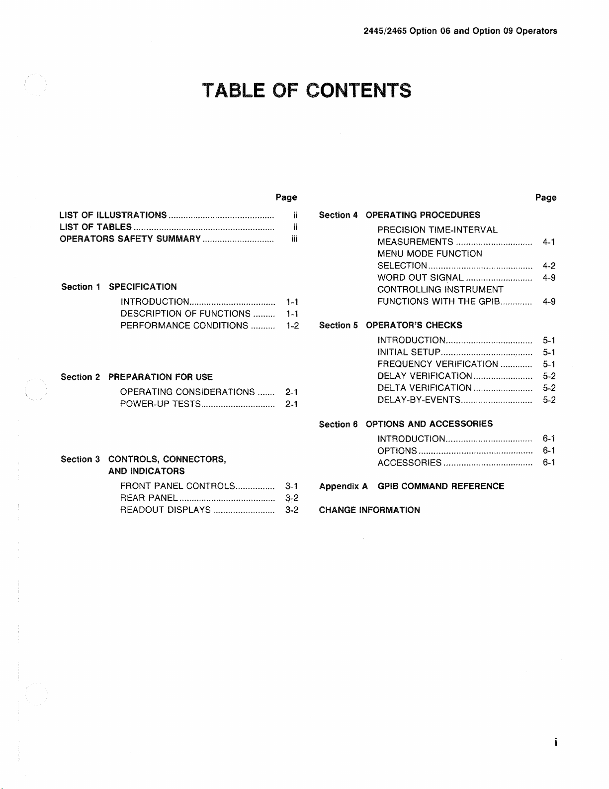
TABLE OF CONTENTS
Page
LIST OF ILLUSTRATIONS............................................. ii
LIST OF TABLES
OPERATORS SAFETY SUMMARY.............................. iii
Section 1 SPECIFICATION
Section 2 PREPARATION FOR USE
Section 3 CONTROLS, CONNECTORS,
...........................................................
INTRODUCTION....................................
DESCRIPTION OF FUNCTIONS
PERFORMANCE CONDITIONS
OPERATING CONSIDERATIONS
POWER-UP TESTS............................... 2-1
AND INDICATORS
FRONT PANEL CONTROLS
REAR PANEL
READOUT DISPLAYS
........................................ 3-2
.........................
........
.........
......
................ 3-1
ii
...
1-1
...
1 -1
...
1-2
2-1
3-2
Section 4 OPERATING PROCEDURES
PRECISION TIME-INTERVAL
MEASUREMENTS................................
MENU MODE FUNCTION
SELECTION............................................
WORD OUT SIGNAL
CONTROLLING INSTRUMENT
FUNCTIONS WITH THE GPIB
Section 5 OPERATOR’S CHECKS
INTRODUCTION
INITIAL SETUP
FREQUENCY VERIFICATION.............
DELAY VERIFICATION
DELTA VERIFICATION
DELAY-BY-EVENTS..............................
Section 6 OPTIONS AND ACCESSORIES
INTRODUCTION
OPTIONS................................................
ACCESSORIES
Appendix A GPIB COMMAND REFERENCE
CHANGE INFORMATION
...........................
....................................
...............................
........................
........................
....................................
.....................................
............
.......
Page
...
4-1
...
4-2
.. .
4-9
....4-9
.. .
5-1
.. .
5-1
.. .
5-1
.. .
5-2
.. .
5-2
...
5-2
.. .
6- 1
...
8- 1
.. .
6-1
Page 4
24 45/2465 Option 06 an d Option 09 Operators
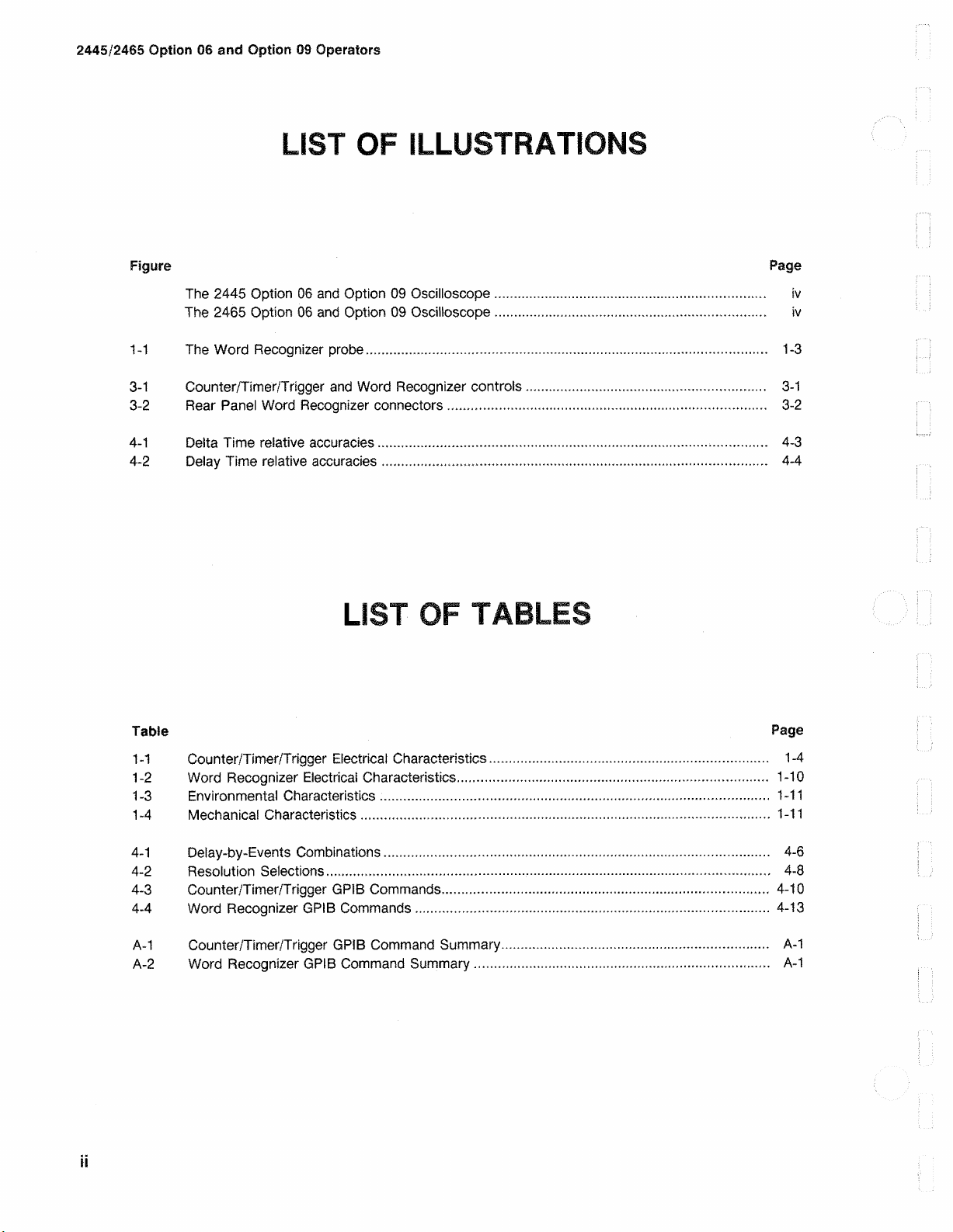
LIST OF ILLUSTRATIONS
Figure Page
The 2445 Option 06 and Option 09 Oscilloscope
The 2465 Option 06 and Option 09 Oscilloscope..................................................................
1 -1 The Word Reco g n iz e r probe................................................................................................... 1-3
3 -1 Counter/Timer/Trigger and Word Recog niz e r controls........................................................... 3-1
3-2 Re a r Pan e l Word Recognizer connectors
4 - 1 Del ta Time relativ e accuracies.................................................................................>
4-2 D elay Time relative accuracies
.............................................................................................. 4-4
.............................................................................. 3-2
.................................................................. iv
tv
.............
4-3
LIST OF TABLES
Table Page
1-1 C ounter/Timer/Trigger Electric a l Characteristics
1-2 Word Recognizer Elect r i c a l Characteristics.....
1-3 Environmental Characteristics
1-4 Mechani cal Characteristics
4-1 Delay-by-E ve nts Combinations............................................................................................... 4-6
4-2 Resolution Selections
4-3 Counter/Timer/Trtgger GPIB Commands................................................................................ 4-10
4-4 Word Recogniz er GP!B Commands....................................................................................... 4-13
A-1 Counter/Timer/Trigger GPIB Command Summary
A-2 Word Recogn izer GPIB Command Summary
ii
............................................................................................................ 4-8
.
............................................................................................... 1-11
.................................................................................................... 1-11
.................................................................... 1-4
....................................................................... 1-10
................................................................ A-1
........................................................................ A-1
Page 5
2445/2465 Option 06 and Option 09 Operators
OPERATORS SAFETY SUMMARY
The general safety information in this part of the summary is for both operating and servicing personnel.
Specific warnings and cautions will be found throughout the manual where they apply and do not appear in this
summary.
Terms in This Manual
CAUTION statements identify conditions or practices
that could result in damage to the equipment or
other property.
WARNING statements identify conditions or prac
tices that could result in personal injury or loss of
life.
Terms as Marked on Equipment
CAU T ION indicates a perso nal injury haz a r d not immedi
ately accessible as one rea ds the markin g s, or a ha zar d to
property, including the equip ment itself.
DANGER indicates a pers o n al injury haza r d immediately
acce s sible as one read s the mark in g .
Symbols in This Manual
This symbol indic a te s where applicable cau
tionary or other informatio n is to be found. For
maximum and mi n i mum input voltage s ee
Table 1-2 .
Symbols as Marked on Equipment
^ D A NGER — High voltage.
Grounding the Product
Th is product is ground e d through the grounding condu c to r
of the power cord. To avoid electrical shock, plug the
power cord into a properly wired rec ep ta c le be f o r e con
necti ng to the product input or output termin a ls . A protec
tive ground connectio n by way of the grounding conducto r
in the power cord is essential for safe operation.
Danger Arising from Loss of Ground
Up on loss of the protective-ground conne cti o n, all acces s i
ble conductive parts (including knobs and controls that
may appear to be insulating) can render an electric shock.
Use the Proper Power Cord
U se only the power cord and connector spec ifi e d for you r
product.
U se only a power cord that is in good condition.
Use the Proper Fuse
To avoid fire haza r d , use only a fuse of the correct type,
voltage rating an d current rating as spec ified in the parts
list for your product.
(? ) Protective go u n d (ear th ) termina l.
/ \ ATTENTIO N — Re fer to ma nual .
Power Source
This product is intende d to operate from a power sourc e
that does not apply mor e than 250 volts rms between the
supply conductors or between either supply conductor and
ground. A protective grou n d connection by way of the
grounding conductor in the power cord is essential for safe
operation.
Do Not Operate in Explosive Atmospheres
To avoid explosion, do not operate this product in an
explosi ve atm o s p he re unless it has been spe c i fi c a ll y
certified for such operation.
Do Not Remove Covers or Panels
To avoid perso n a l injury, do not remove the product cov
ers or pan e ls. Do not operate the product without the cov
ers and panels properly installed .
Page 6
2445/2465 Option 06 and Option 09 Operators
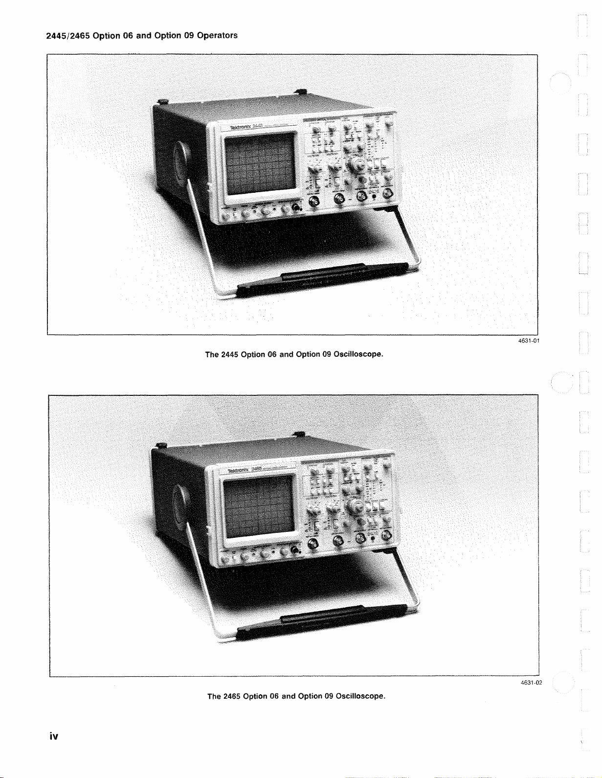
The 2445 Option 06 and Option 09 Oscilloscope.
4631-01
The 2465 Option 06 and Option 09 Oscilloscope.
4631-02
Page 7
2445/ 2465 Option 06 and Option 09 Operators
SPECIFICATION
Section 1
INTRODUC TION
The Counter/Tim er /T rigg e r (Optio n 06) and Counter/
Timer/Trigger with Word Recogniz e r (Optio n 09) add the
following four cap a bi l iti e s to the TEKT R O N IX 2445 an d
2465 Oscillo s c o p e s :
1 . P recisi o n time-in te rv a l me a s u r e ment.
2. Event and frequen c y counting.
3. Dei a y - b y -events triggering.
4. Log ic trigger ing.
The 17-bit W ord R e c ogniz e r pro b e of Option 09
extends the capa b ilit ie s of these functions. The function s
describ ed in this man ual wh ic h use the Word Recog n iz er
require the Word Rec o g nizer Optio n 09 and the 17-b i t
Word Recogn iz e r probe.
The Counter/Timer /T rigg e r and Counter/Timer/Trigger
with Word Recog nizer options use the 2445 an d 2465
alphan um er ic crt readou t to displa y configuration me nus
and function resu lt s.
1 244 5/2 4 6 5 Option 06 and O p ti on 09 Counte r /
Timer/Trigger and Wor d Reco g n izer Ref erence Guide
Each instrument containing the Word Rec o g n iz e r is pro
vid ed with the following standard access o r ie s in additi o n to
those mention e d for the Counter/Tim er /T rigg e r:
1 P64 07 Word Recogniz e r Probe packa g e .
The following optional acces so r y is also av aila b l e for
these options:
1 244 5 /2 46 5 Option 06 and Option 09 Counte r/
Timer/Trigger and Wor d Rec o g n i z e r Ser v i c e Manual
DESCRIPTION O F FU NCTBON S
Precision Time-interval Measurements
Prec i s i o n delay and preci s i o n delta -tim e mea s urement s
are ma d e possible by a precisio n timer which directly
me a s ures the time interval betwee n the start of the A
Swe e p an d the start of the B Sweep. Direct meas urement
capability operates when the B Swe e p is triggera ble after
dela y as well as in RUN AFT D LY. Direc t m easuremen t
incr e ases resolution and acc u r a c y.
The oscilloscope operators m a nual sho u ld be consulted
for operating information regar d ing the 2445 and 2465
instruments. The ope r ati o n an d specification s of functions
not des c ri b e d in this manual rema in uncha n g ed.
in addition to the standa rd instrument’s stand a rd
accesso r ie s, the follo w in g stand a rd accessories are pro
vided with each instrument containing the 2445/ 24 6 5
Option 06 Counter/T im e r/T r ig ge r:
1 2445/246 5 Op t ion 06 an d Option 09 Counter/
Timer/Trigger an d Word Recogn iz e r Operators
Man u a l .
1 2445/2465 Opti o n 06 an d Option 09 Counter/
Timer/Trig ger and Wor d Rec ogniz er Reference Ca rd
Only one of the four functions provid e d by th e
Counter/Timer/ Tri gge r Optio n (Precis io n Tim e - in te r v al
Mea s u re ment, Even t Counti n g , Dela y - by - E v e n ts Trigger
ing, and Logic Triggering) can be active at a gi ven time
with the exception that preci s ion time measurement s are
avai lable with the Logic Trigger functio n whe n the B
Swe e p is triggered by the Word Recognizer .
W hen ti m in g m e a s u r e m e n t s are reques te d whil e a
conflicting Counter/Timer/Trigger (C/T /T ) function is
opera tin g , the timin g mea s u re ment is dis p la y e d with the
accu ra c y and res olution associ a te d with a 2445/24 6 5
instrume nt not equipped with the Counter/ Timer/Trigg er
Optio n. The word SET following the time meas u r e ment
indicates this condition.
Ί-1
Page 8
Specific ation
2445/2465 Option 06 and Option 09 Op erators
Pulse-width m e a s urement is m ade easier by Alternate
Slope (ALT SLP) mode. W hen this mode is selected, the
delay e d sweep controlle d by the Δ REF O R DLY POS con
trol triggers on the slope indicated by the SLOPE indicator,
and the delayed swe ep controlled by the Δ control triggers
on the opposite slop e .
Event Counting (COUNT)
The Event- C o u n ti n g function has three modes: Fre
quency, Pe ri o d, and Tota liz e . Either the A Trigger events
or the 17-bit Word Recog ni z e r (WR ) events (if the Option
09 Word Reco g n iz e r is present) can be counted.
Delay-by-Events (DLY/EVTS)
The De l ay - b y -Even ts function adds the ability to delay a
sweep by a numb e r of events , rather than by an absolute
time interval. Either the A or the B Swee p can be delayed;
the dela y pe ri o d begin s whe n a “ Start” event occurs, and
the duration of the delay is determ i n e d by a number of
occurrences of a “ D el a y ing” event. The sweep to b e
dela y e d , the “ Start” ev ent, the “Delay in g ” event, and the
number of occu rrences of the “ Delaying” event are all
operator sele c ted.
The B swee p can trigger on the word rec o gniz e d by the
Word Recogni z er.
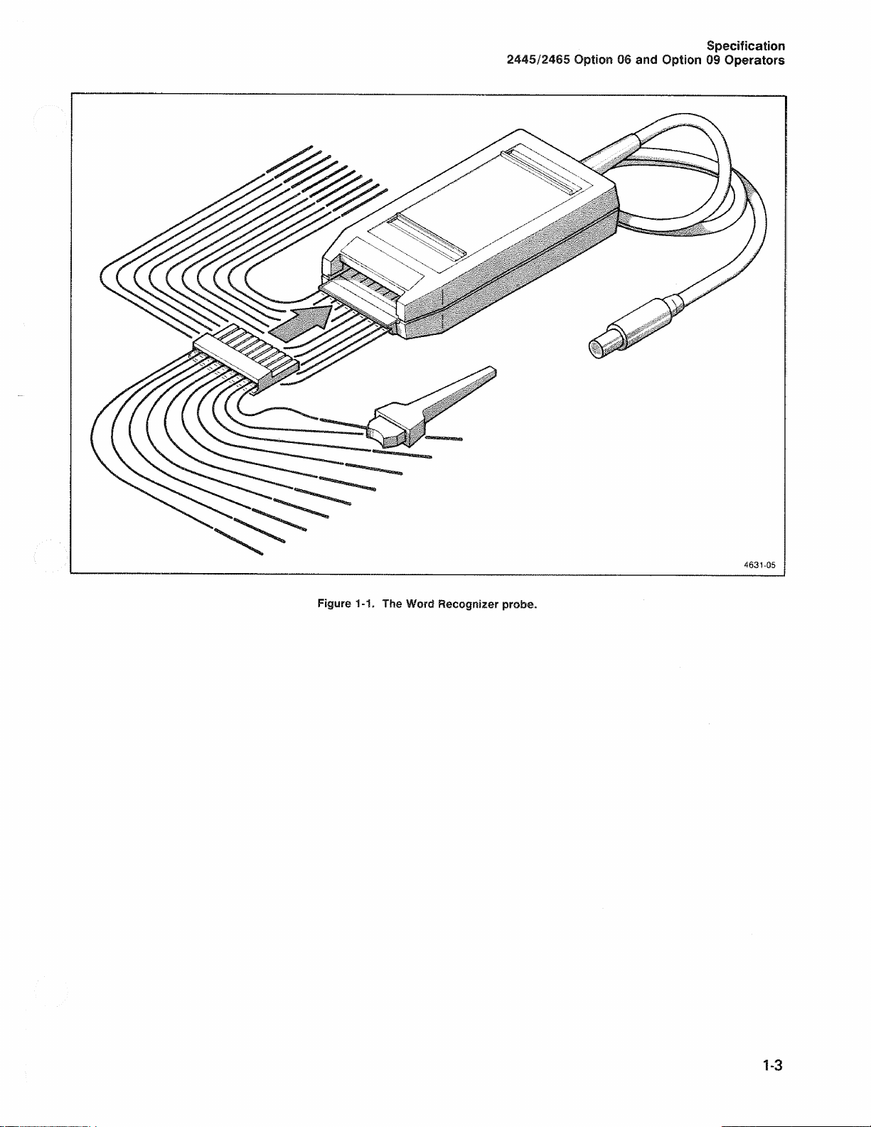
Word Recognizer
The 17-b it Word Recognizer detects any 17-bit digital
word, either synchronously with an external clock or asyn
chronous^. Word occurrences may be counted for fre
que n c y , period, or totalize mea s urement s . A word can
trigger either the A or B Sweep, or the word can be a
delay in g eve n t in the Delay-b y- E v e nts function. The Wo rd
Reco gn iz e r probe is shown in Figure 1-1.
PERFORMANCE CONDITIONS
Excep t as noted in Tables 1-1 through 1-4 of this
manual , the electrical, enviro n menta l, and me c hanic al
characteristics of Option 06 and 09 instruments are identi
ca l to those specified in the respe c ti ve 2445 and 2465
Oscillos c op e Operators man uals.
Logic Trigger (LOGIC-TRIG)
This function add s logic-triggering capabilities. The A
Sweep can trigger on any of the following:
1 . The logical AND of the A a nd the B triggers going
TRU E .
2. The logica l O R of the A and the B triggers going
TRUE .
3. The occ u rr e n c e of a word recog n iz e d by the Word
Rec o g n iz e r.
The electrical characteristics are val i d when th e instru
ment has bee n adjusted at an ambien t te m p er a tu re
betwe e n +20 and +30°C, has had a warm-up perio d of
at least 20 minu te s, an d is operated at a n ambient tem
peratu re betw e en —15 and +55°C (unles s otherw is e
not e d).
Items listed in the “ Perform a n c e Req uir e m e nts ” colum n
are verif ia b le qualitative or quantitative limits that de fi n e
the meas u r ement capabilities of the instrum e n t.
1-2
Page 9
2445/2465 Option 06 and Option 09 Operators
Specification
Figure 1-1. The Word Recognizer probe.
1-3
Page 10
Specification
2445/2465 Option 06 and Option 09 Operators
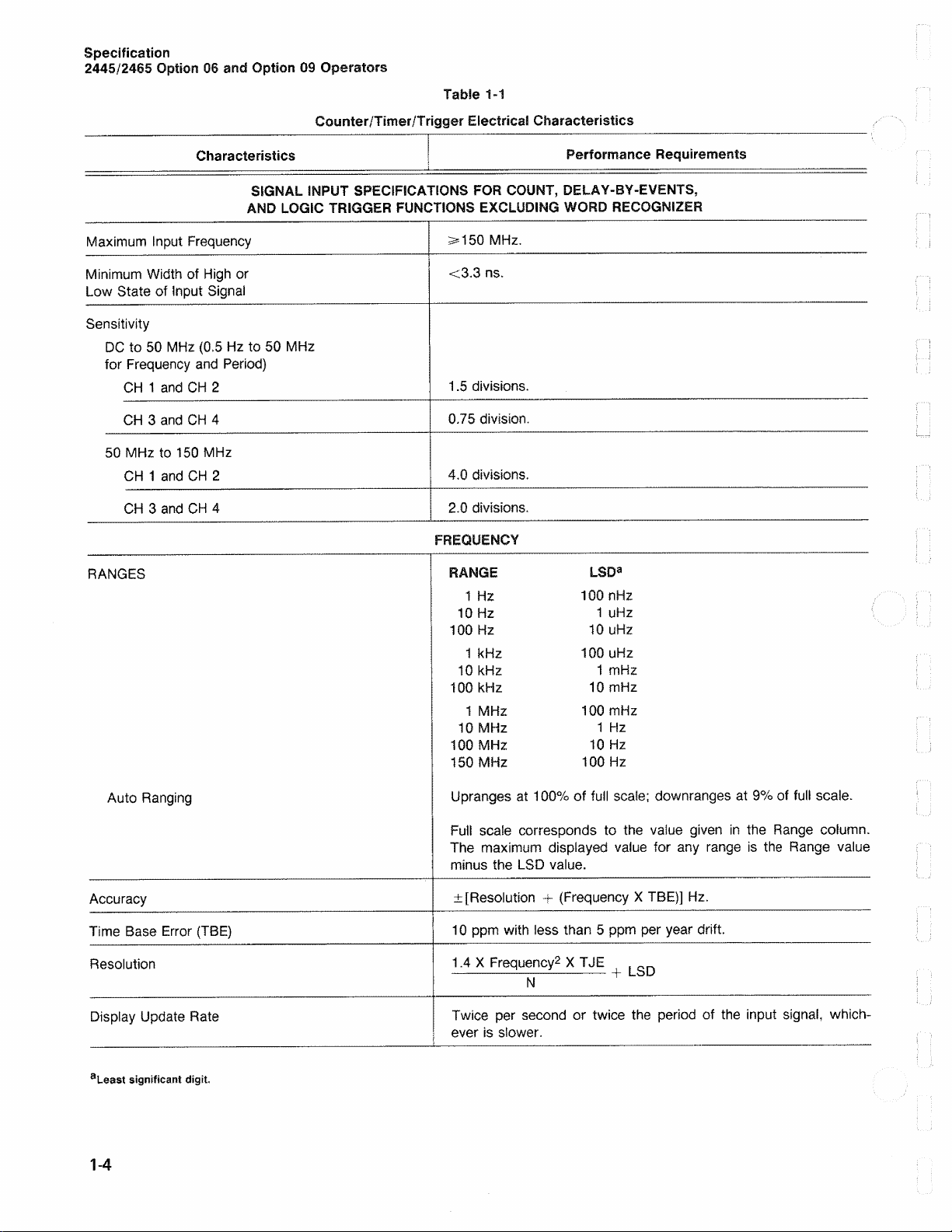
Counte r/Timer/Trigger Electrical Charact eristics
Characteristics | Performance Requirements
SIGNAL INPUT SPECIFICATIONS FOR COUNT, DELAY-BY-EVENTS,
AND LOGIC TRIGGER FUNCTIONS EXCLUDING WORD RECOGNIZER
Table 1-1
Max imum Input Frequency
Min imum W id t h of H i gh or
Low State of Input Signai
Sensitivity
D C to 50 MHz (0.5 H z to 50 MHz
for Fr equ e n cy an d Pe r i od)
C H 1 a nd CH 2
C H 3 and CH 4
50 MH z to 150 MHz
C H 1 and CH 2
C H 3 and CH 4
RA NGE S
33= 150 MH z.
<3.3 ns .
1. 5 divisio n s .
0.75 divisio n.
4.0 division s .
2.0 division s .
FREQUENCY
RANGE LSDa
1 Hz 100 nHz
10 Hz 1 uHz
10 0 Hz 10 uHz
1 kHz 100 uHz
10 kHz 1 mHz
10 0 kHz 10 mHz
1 MHz 10 0 mHz
10 MHz 1 Hz
10 0 MHz 1 0 Hz
150 MHz 100 Hz
Auto Ranging
Accura cy
Time Bas e Err o r (TB E)
Reso lu tio n
Disp la y Upda te Rate
aLeast significant digit
1-4
Upran g es at 100% of full scale; downrang e s at 9% of full scale.
Fu ll scale corresponds to the vaiu e given in the R ang e column.
The maxim u m displayed valu e for an y ra nge is the Rang e value
minus the LS D valu e.
± [Resolutio n + (Fre q u e n c y X TBE)] Hz .
10 ppm with less than 5 ppm per year drift.
1.4 X Freque n c y 2 X TJE ^
N +
Twice per sec o n d or twice the period of the input signai , which
ever is slower.
Page 11
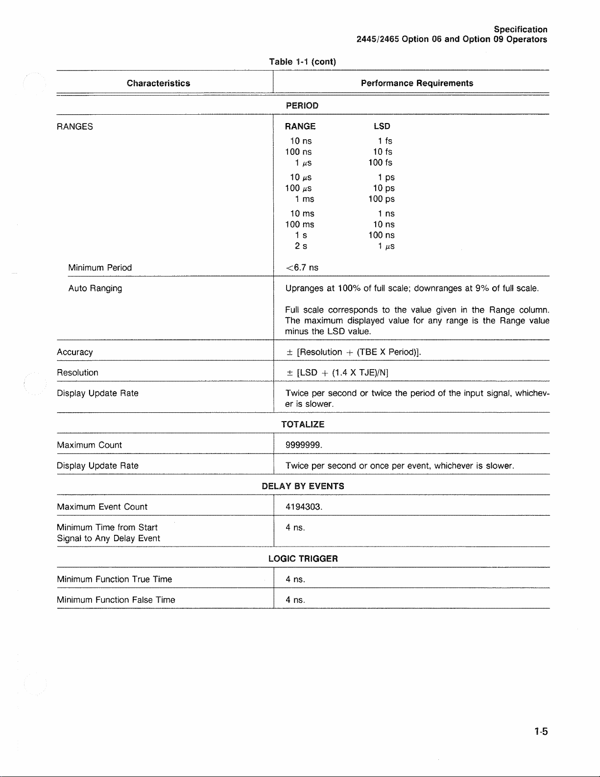
Table 1-1 (cont)
2445/2 465 Option 06 and Option 09 Ope rators
Specification
Performance Requirements
LSD
1 fs
RANGES
Characteristics
PERIOD
RANGE
10 ns
10 0 ns 10 fs
1 με 100 fs
10 μβ
1 ps
10 0 ms 10 ps
1 ms 100 ps
10 ms
1 ns
100 ms 10 ns
1 s 1 00 ns
Mini mum Period
2 s
<6.7 ns
1
Auto Rang i n g Upra n g e s at 100% of full scal e ; downrang e s at 9% of full scal e.
Fu l l scale corresponds to the value given in the Range colum n .
The maximum displaye d value for any range is the Range valu e
min u s the LSD value.
Accura cy ± [Resolution + (TBE X Per iod)].
Res o lu ti o n ± [LSD + (1.4 X TJEJ/N]
Display Update Rate Twice per second or twice the perio d of the input signa l, whichev
er is slower.
TOTALIZE
Max imum Cou nt
9999 9 99 .
Disp la y Upda te Rat e Twice per second or onc e per eve n t, which e v e r is slow e r .
DELAY BY EVENTS
Maximum Eve nt Coun t
Minimum Time from Start
4194 3 03 .
4 ns.
Sig n a i to Any Del ay Ev ent
LOGIC TRIGGER
Min imum Fu n c ti o n Tru e Time 4 ns.
Minimum Fun c ti o n Fal se Time
4 ns.
1 -5
Page 12
Specification
2445/2465 Option 06 and Option 09 Operators
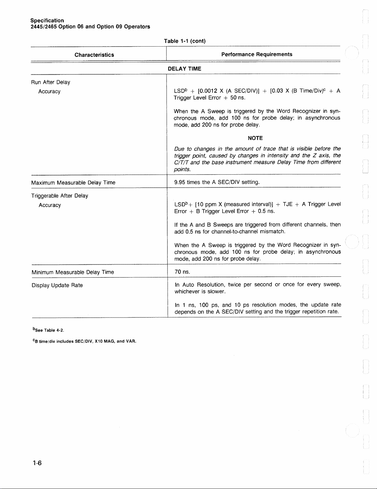
Table 1-1 (cont)
Characteristics
R un After Deia y
Acc u r a c y
Ma x imum Mea s u ra b le Del ay Time
Trig g e rable After Dela y
Acc u r a c y
Performance Requirements
DELAY TIME
LSDb + [0.0012 X (A SE C/DIV)] + [0.03 X {B Time/Div)c + A
Trigger Leve l Error + 50 ns .
Wh e n the A Sweep is triggere d by the Word Recogn iz er in syn
chronous mode , add 100 ns for probe delay ; in asynchronous
mo d e, add 200 ns for probe de lay.
NOTE
Due to changes in the amount of trace that is visible before the
trigger point, caused by changes in intensity and the Z axis, the
CfT/T and the base instrument measure Delay Time from different
points.
9.95 times the A SEC/DIV setting.
LSDb+ [10 ppm X {mea s u r e d interval)] + TJ E + A Trigger Le vel
Error + B Trigger Level Erro r + 0.5 ns.
If the A and B Swee ps are triggered from different channels , then
add 0.5 ns for channel-to -c h an n e l mismatc h .
Minim um Measu ra b le Delay Time
Disp l a y Update Ra te
bSee Table 4-2.
CB time/div includes SEC/DIV, X10 MAG, and VAR.
When the A Sweep is triggered by the Word Recogniz e r in syn
chronous mode, add 100 ns for probe deiay; in asynchronous
mo d e, add 200 ns for probe dela y .
70 ns.
In Auto Resolution, twice per second or once for every swe ep,
whichever is slower.
In 1 ns , 100 ps, an d 10 ps resolution modes, the update rate
depen d s on the A SEC/DI V setting an d the trigger repetition rate.
1-6
Page 13
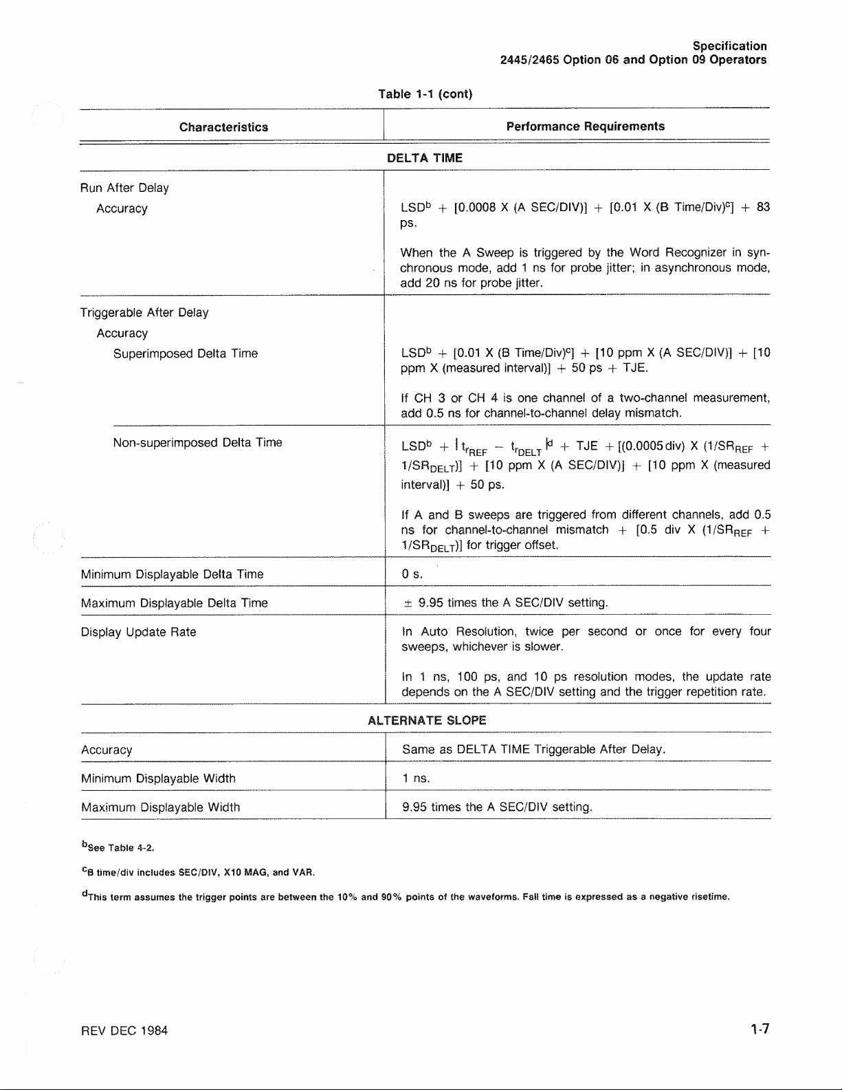
Table 1-1 (cont)
Specification
2445 /2465 Option 06 and Option 09 Operators
Characteristics
Run After De l a y
Accuracy
Triggera bl e After Delay
Accuracy
Super im p o s ed Delta Tim e
Non-sup e rimposed Delta Tim e
Performance Requirements
DELTA TIME
LSDb + [0.0008 X {A SE C / D I V ) ] + [0. 0 1 X (B Tsme /D i v)c ] + 83
ps.
Whe n the A Sweep is trigge re d by the Word Recog n i z e r in syn
chronous m ode, add 1 ns for prob e jitter; in asynchron o u s mode,
add 20 ns for prob e jitter.
LSDb + [0.01 X (B Ttme/Div)c] + [10 ppm X (A SEC / DIV)] + [10
ppm X (meas ured interv al) ] + 50 ps + TJE.
if C H 3 or CH 4 is one ch a nne l of a two-channel m easure ment,
add 0.5 ns for channe l - to - c h anne ! dela y misma tc h .
LSDb ~j “ I tj-p^p — Vq £| _"t ^ [(0.0005 div) X (1/SRp^p 4-
1 /SRDElt)] + [10 pp m X (A SE C /D I V ) ] + [10 ppm X (measu r ed
interval)] + 50 ps.
If A and B sweeps ar e triggered from different ch a nne ls , ad d 0. 5
ns for channel- t o -c h a n n e l mism a tc h + [0.5 div X (1/SRref +
1/SRqelt)] ior trigger offset.
Minimum Disp la y a b le Delta Time
Maxim um Display a b ie Delta Time
Disp la y Update Rat e
0 s.
± 9.95 times the A SEC / D I V settin g .
In Auto Reso lu ti o n , twice per sec o n d or once for ever y four
sweeps, whichever is slower.
In 1 n s , 100 ps, and 10 ps resolution mode s, the updat e ra t e
depends on the A SEC/ D I V setting and the trigger repetition rate .
ALTERNATE SLOPE
Accuracy
Minim u m Dis p la y a b le Width
Maximum Displaya b le Width
^See Table 4-2.
CB time/div includes SEC/DIV, X10 MAG, and VAR.
. . . . . . . . . . ..
dThis term assumes the trigger points are between the 10% and 90% points of the waveforms. Fait time is expressed as a negative risetime.
__
Same as DEL T A TIM E Triggerable After Delay.
1 ns.
9.95 times the A SEC/ DIV setting ,
REV DEC 1984
1 -7
Page 14

Specification
244 5/24 65 Option 06 and Option 09 Operators
Tabl e 1-1 (c ont)
Characteristics
DEFINITIONS
Performance Requirements
A Trigger Level Error = (A Trigger L evel Readout Error)/SR A.
B Trigger Level Error = (B Trigger Le vel Readout Error)/SRB .
trREF = risetim e , referen c e trigger sign a l .
trDELT = riseti me, delta trigger signal .
SRA = slew rate at trigger point, A sweep trigger signai in div/sec.
SR g — slew rate at trigger point, B sweep trigger signa i in div/sec.
SRr ef = sle w rate at trigger point, referen c e trigger signai in div/sec.
S R De lt = s,ew rate at trigger point, delta trigger signal in div/sec.
TJE = trigger jitter error.
= (Trigger Jitter)/ \/N .
Fo r de ia y or delta time, dis reg ar di ng no is e in the sign a i, this term contributes <1 LSD if the slew rate is greater than
0.03 vertical div/ns or if the slew rate is greater than 30000 vertical div/horizontai div.
Trigger Jitter = yfReference Trigger Signa l Jitter)2 + (Delt a Trigger Signal Jitter}2 + (A Sweep Trigger Sig n a l Jitter)2'.
Refe r e nce Trigger Signai Jitter = (ens + e nREF )/SRref-
= 0 for Freq uency mo de.
en s = sco p e noise in div .
= 0.0 5 div for HF R EJ trigger couplin g.
= 0.1 div for DC trigger coup l in g , 5 m V to 5 V sensitivity.
= 0.1 5 div for DC trigger coupling, 2 mV sensitivity.
enREF = reference signai rms nois e in div.
Del t a Trigger Signal Jitter = (ens + e nDELT ) /S R d e l t -
= 0 for Frequen c y or Delay mode.
0nDELT ^ C*e**a S'9 nai rmS n0ise *η ^ ν ·
A Trigger Sig nal Sweep Jitter = (eng + en A)/SRA.
enA = A sweep trigger signai rm s nois e in div .
1-8
Page 15

Table 1-1 (cont)
2445/2465 Option 06 and Option 09 Operators
Specification
Characteristics
Performance Requirements
Whe n the Word Re c o g n iz e r supplies a trigger in synchronous mode, the trigger jitter of the associated trigger sig n a i
is <1 ns; in asynchron o u s mode, the associated trigger signal jitter is <20 ns.
N ===== number of ave r a g es during measu re ment interval,
=== see Table 4-2 for Del ay or Delt a Tim e.
= (measu re d frequen c y ) X (Measureme nt Interval) for Fre que n c y or Pe r iod.
Measurement Inte r v a l = 0. 5 s or two periods of meas u re d signal, whichever is greater.
aLeast significant digit.
^See Table 4-2.
CB time/div includes SEC/DIV, X10 MAG, and VAR.
^This term assumes the trigger points are between the 10% and 90% points of the waveforms. Fat! time is expressed as a negative risetime.
1-9
Page 16
Specific ation
2445/2465 Option 06 and Option 09 Operators
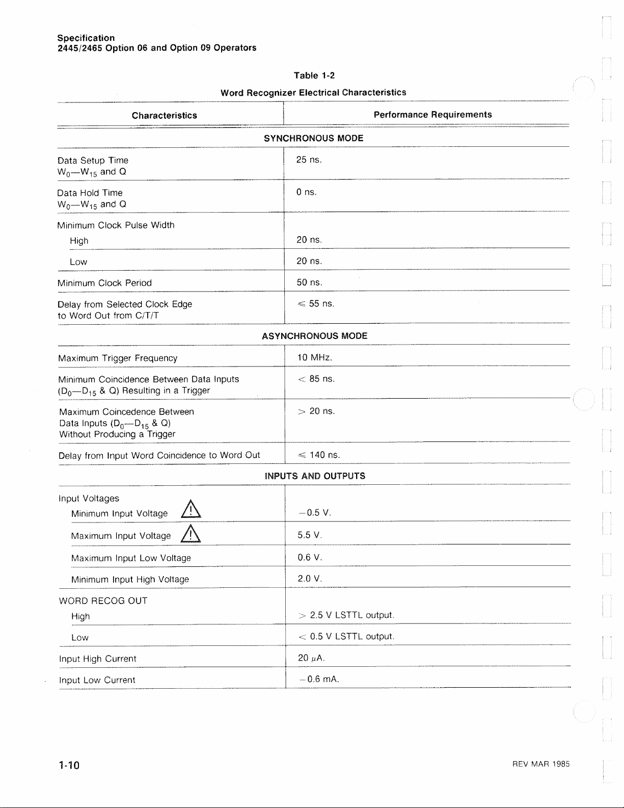
Word Reco gnize r Electrical Characteristics
Tab le 1-2
Characteristics
Data Setup Time
W0 —W15 and Q
Data Hol d Time
W0 —W15 and Q
Minim u m Clock Pulse Width
Hi gh
Low
Minim u m Clock Perio d
Del a y from Selected Clock Ed ge
to Wo r d Out from C/T/T
Maxim um Trigger Fre q u ency
Mini mum Coincidence Betwe en Data Inputs
(D0—D15 & Q) Resultin g in a Trig g e r
Performance Requirements
SYNCHRONOUS MODE
25 ns.
0 ns.
20 ns.
20 ns.
50 ns.
*£ 55 ns.
ASYNCHRONOUS MODE
1 0 MHz.
< 85 ns .
Maximum Coin c ed e n ce Be tween
Data Inputs (D0—D15 & Q)
Without Producing a Trigger
De l a y from Input Word Coinci dence to Wo r d Out
Input Voltages *
Min imum input Voltage / - \
Maximum Input Voltage / t \
Maxim u m Input Low Volta g e
Min imum Inpu t High Volta g e
WO RD RECOG OUT
Hi gh
Low
Input Hi gh Current
Input Low Current
> 20 ns.
140 ns.
INPUTS AND OUTPUTS
-0.5 V.
5.5 V.
0.6 V.
2.0 V.
> 2.5 V LSTTL output.
< 0. 5 V LS T T L output.
20 μΑ.
0.6 mA.
1- 10
REV MAR 1985
Page 17
2445/2465 Option 06 and Option 09 Operators
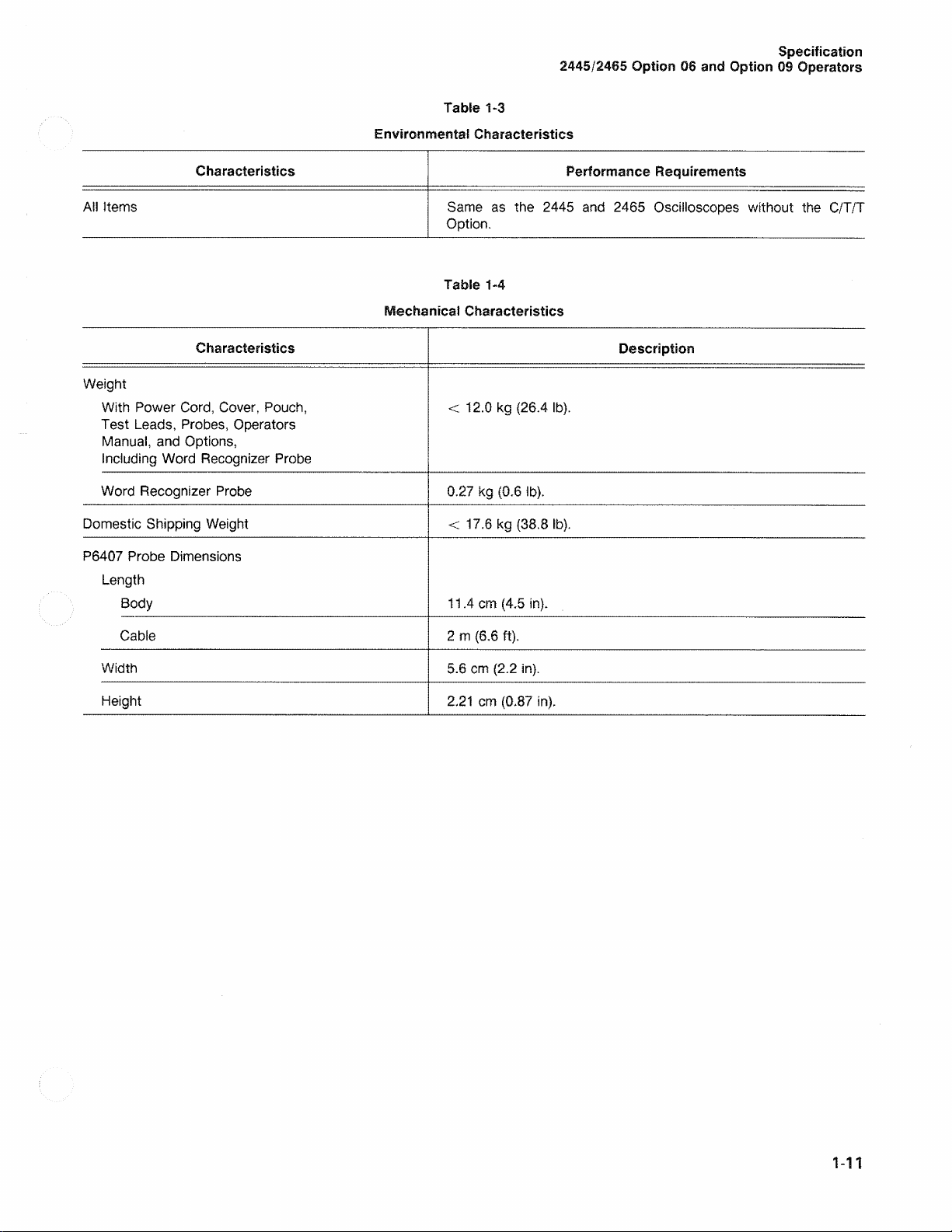
Table 1-3
Environmental Characteristics
Specification
Characteristics
All Items
Same as the 2445 an d 2465 Oscillosco p e s without the C/T/T
Option .
Table 1-4
Mechanical Characteristics
Characteristics Description
Weig h t
With Power Cord , Cov e r , Pouch,
< 12.0 kg (26.4 lb ).
Test Le a d s , Prob e s , Opera to rs
Ma n u a l , and Options ,
Inclu d i n g Word Recognizer Probe
Word Recognizer Pr obe
Dome stic Shipping Weig h t
0.27 kg (0. 6 lb) .
< 17.6 kg (38.8 lb ).
P64 07 Probe Dimensions
Length
Body 11 . 4 cm (4.5 in).
Performance Requirements
Cable
Width
Heig h t
2 m (6.6 ft).
5.6 cm (2.2 in).
2. 21 cm (0.87 in).
1-11
Page 18

Page 19

2445/2465 Option 06 and Option 09 Operators
PREPARATION FOR U S E
Section 2
OPERATING CONSIDERATIONS
A GATE OUT Termination
To prevent mea su r e ment errors, of a s m uch as
±2.0 n s in Preci s ion Delay an d ±0.5 n s in Precisio n Deit a
Time, the A G ATE OUT signai must not be termin a ted in
less than 10 kfi.
POWER-UP TESTS
Befo re initia lly turning on power to the instrument, read
Section 2, “Preparati o n for Use, ” in the osc illo s c o pe
operators man ual an d follow the safety and pre c aut io na ry
information des c r ibed there.
The power-up tests, automatically per f or med ea c h time
the oscilloscope is turn e d on, verify both the oscilloscope
circuitry an d the option circuitry. Tests , specific a lly applica
bl e to Option 06 a n d Option 09, are integrated into the
power-u p tests of the host oscilloscope, an d the tests con
sist of two mai n parts: K ernel tests and Confide nce tests.
A power-up test failure will either flash the A SWP
TRIG’D indicator or display a diagnostic mess age in the
crt reado u t. Pressing in the A/8/MENU switc h (A/B TRIG
in the crt read ou t) m ay pla ce the instrument into a usable
mode. Even if the instrume nt then functions ade q u ately for
your particular requirement, it shou ld be refe rr e d to a
qualifi ed service tec h n ic i a n for repair of the problem as
soon as possible.
2 -1
Page 20

Page 21
2445/2 465 Option 06 and Option 09 Operators
CONTROLS, CONNECTORS,
AND INDICATORS
Section 3
The controls, connecto rs , and Indicators used in the
opera tio n of the Option 06 Counter/Timer/Trigger and
Opti o n 09 Counter/Timer/Trigger with Word Recognizer
are describ e d in this section, alon g with any controls
whos e function is affecte d by these options. For details
about the controls use d to operate the standard oscillo
scope , re fer to the respective instrument operato rs
manua l . There are no controls added to the front pane l to
acco m modate thes e options, but the B TRIG GER MO DE
indicato r group has two extra positions, MENU and ALT
SL P,
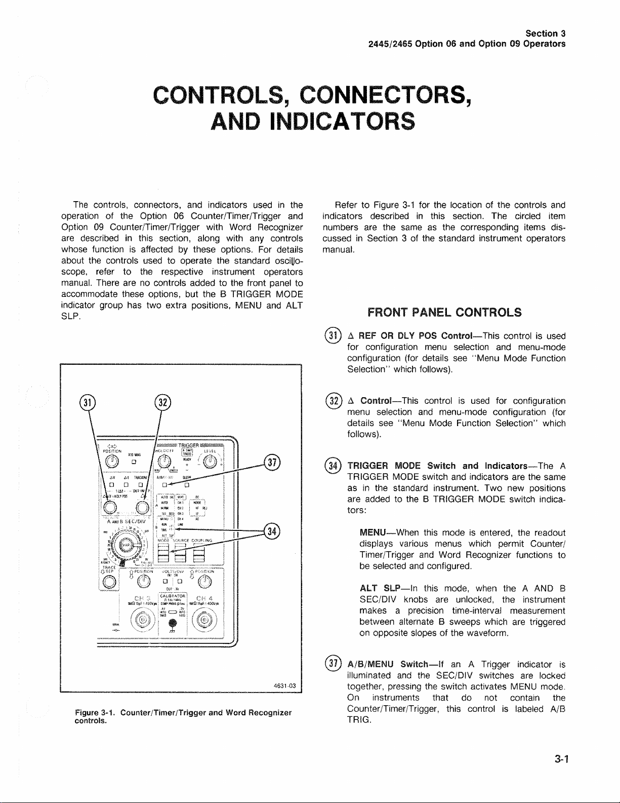
Refe r to Figure 3- 1 for the location of the controls a nd
indicators describ e d in this section. The circle d ite m
number s are the same a s the corresponding item s dis
cusse d in Section 3 of the standard instrument operators
man u a l .
FRONT PANEL CONTROLS
(3?) Δ REF OR DLY POS Control^This control is us ed
for confi gu ra tio n me nu se l e c ti o n and men u-mode
configuration (for details se e “ Menu Mod e Fun c ti o n
Selection” which follows).
(32) A Control—Thi s control is us ed for configuration
men u selec ti o n and men u - m ode configuration (for
details see “ Men u Mode Funct ion Selection” whi c h
follows).
(3?) TRIGGER MODE Sw itch and Indicators—The A
TRIG G E R M ODE switch and indicators are the same
as in the standa rd instrument. Two new positions
are adde d to the B TRIGGER MODE switch indica
tors:
4631-03
Figur e 3-1. Counter/Timer/Trigger and Word Recognizer
controls.
MENU—W hen this mod e is entered, the read ou t
displays vario u s menus whic h permit Counter/
Timer/Trigger and Word Recogniz e r functions to
be selected and configured.
ALT SLP—In this mode, when the A AND B
SEC/DIV knobs a r e unloc k e d , the instrum ent
make s a precisi o n time-interval measu re m e nt
betwee n alterna te B sweeps whi c h are triggered
on opposite slopes of the waveform .
(37) A/B/MENU S witch—If an A Trigger indicator is
illuminat ed an d the SEC/DIV switches are locked
together, pressi n g the switch activates ME NU mo d e.
On instruments that do not contain th e
Counter/Timer/ Tr igge r, this control is labe l e d A/B
TRIG .
3-1
Page 22
Controls, Connectors, and Indicators
2445/2465 Option 06 and Option 09 Operators
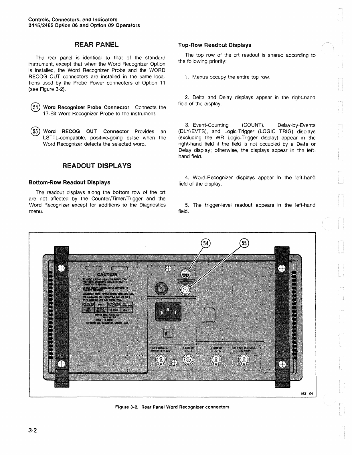
REAR PANEL
The rear pa ne! is identica l to that of the stand ard
instrum ent , except that when the Word Reco g n i z e r Optio n
is inst ailed , the Word Recognizer Pro b e an d th e W ORD
RECOG OU T connectors are installed in the same loca
tions used by the Pr obe Power connectors of Option 11
(see Figure 3-2).
(54) Word Recognizer Probe Connector—Connects the
17-Bit Word Recog n iz e r Probe to the instrument.
(55) Word RECOQ OUT Connector—Pro v ides an
LSTTL- co m p aii b le , posi tive-going pulse whe n the
Wor d Recogn i z er detects the selected word.
READOUT DISPLAYS
Bottom-Row Readout Displays
The reado u t displays along the bottom row of the crt
are not affecte d by the Counter/Timer/Trigger and the
Word Rec ognizer except for additions to the Di a gnostic s
me nu.
Top-Row Readout Displays
The top row of the crt readout is sha red according to
the following priority:
1 . Menus occupy the entire top row.
2. De l ta an d De i ay displays appea r in the right-hand
field of the display.
3. Event-Countin g (COUNT), Delay-by-Events
(DLY/EVTS), a nd Logic-Tri g g er (LO G I C TRIG) displays
(exclu d ing the WR Logic-Trigge r disp lay) appear in the
right-han d field if the field is not occupie d b y a Delta or
Delay display; otherwise, the displays appe a r in the left-
ha nd field.
4. Word-Recognizer displays appear in the left-hand
field of the display.
5. The trigger-level readout appea r s in the left-hand
field.
3-2
Figure 3-2. Rear Panel Word Recognizer connectors.
Page 23

2445/246 5 Option 06 and Option 09 Operators
OPERATING PRO CE DU RE S
Section 4
Cons ult the 2445 and 2465 Operato rs manuals for
basic operating information and techniq u e s that should be
cons id er e d befor e attempting to make any measure m e nts
with your instrument.
PRECISION TIME-INTERVAL
MEASUREMENTS
Time-interval Measurements
Th e Counter/Timer/Trigger Option has n o effect on cur
sor mea s u r ements except that At and 1/At measu re m e nts
with cursors are available when the B Sweep is delaye d by
even ts .
Precision Delay-Time and Precision Delta-Time
Operation
Opera ti n g procedu re s for precisio n delay-time and
delta-time function s are the same as the operating pro
cedu re s for delay-time and delta-time functions in a 2445
or 2465 instrument without the C/T/T Option.
Wh e n e v e r the display for prec is io n time-interv al meas
ureme n ts is upd a t e d , the last letter of the units symb o l
blink s. The displaye d resolution is se le c table (see “Resolu
tion Selection” in this section).
Wh en a conflicting Counter/Timer/Trigger function
(Delay -b y -E v e n ts or Even t Coun tin g ) is active, the preci
sion time- inte rv al measuremen t function is not avai la b l e ,
but it is re p l a c e d by a time measure m e n t having the reso
lution and accurac y of a 2445 or 24 6 5 without th e
Counter/Timer/Trigge r Option. In this ca s e, the word SET
appe a r s following the time-measurement displa y .
if the measu r e ment is not avai la b l e , one of the followin g
messages is displa ye d to ind ic ate why:
AVERAGING
NO A TRIGGER
MISSING B TRIG At least one A Swe e p
B Triggered After Delay Mode
The C/T/T Option allows precisi on time me a s u r e m e n t s
even while in the B TRI G AFT DLY m o de. Th e B Trigger
controls operate in the same manner with the C/T/T
Option as in a 2445 or 2465 not equipped with the option.
An instrument with a C/T/T mea s u r e s the time from the
start of the A Sweep to the start of the B Swee p , whether
the B Trigger MODE is R UN AF T DLY or TRIG AF T D LY.
The m e a s u r e ment give s dela y times directly when B
Sweep is operated without delta time.
Whe n B Sweep is used with delta time or 1/del ta time,
the instrument measur e s the inte rv a l from the start of A
Sweep to the start of B Sw e ep. A measure m ent is m ade
for ea ch of the two delay s controlled by the A RE F OR
DLY POS an d A controls. The difference between these
measur em e n ts gives the delta-time result.
If the transition time s of the sig nals being mea s ured are
not negligib le relative to the measu re m e nt , rotate the B
SEC/DIV switch to provide a magn if ie d view of the signal s .
More sw ee ps ar e requir e d
for the select e d
meas ur e m e nt resoluti on .
No A Trigger even t w as
rece i v ed.
occurre d without a B Trigger
even t during the A Swee p.
Th e SET disp la y also occurs during precis io n time
meas ur e m e nt s any time a control switch or delta control is
operated. The SET display rema in s for two seconds, and
then the precisi on time measure m en t is disp la ye d if it’s
avai la b l e ; e.g.:
starting display: DLY 213.3693ms
delta control rotated: DLY 198.1ms SET
fina l displa y : DLY 197.8849ms
This magni fi e d view shows the intersection points of
the two delay e d sweep s . The time interval measu r e d is the
time between these points. Adjusting the B TRIGGER
LEVEL and the VERTICAL POSITION selects various
intersection poin ts . Wh en mak ing a dual-chan n el delta-time
meas u r ement, if the points of interest can not be ma de to
intersect by the LEVEL and PO SITION controls, the poin ts
can be forced to intersect by redu c i n g the displayed ampl i
tude of the sig nal that appear s later in the display and
then read ju sting the LE VEL and POSITION controls.
4-1
Page 24
Operatin g Procedures
244 5/24 65 Option 06 and Option 09 Operators
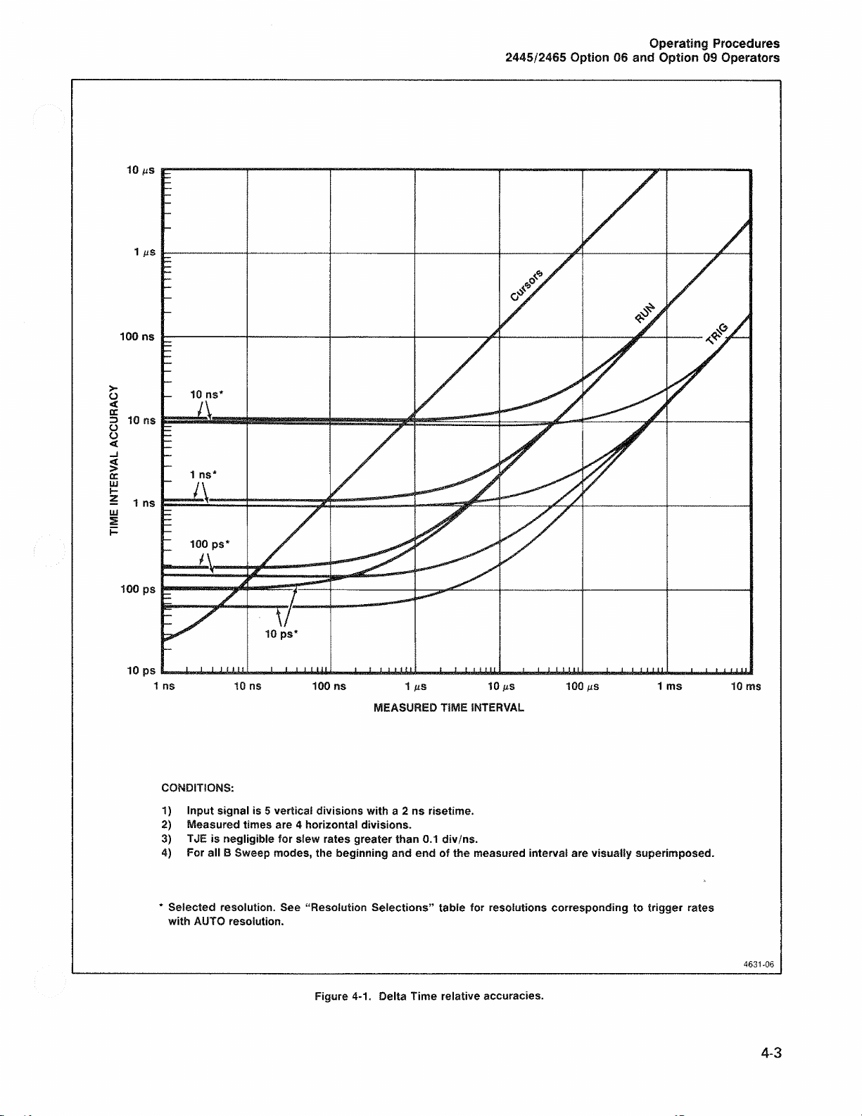
The relative acc u ra c i e s of delta-time an d delay-time
measu r ements using cursors (delta tim e only), RUN AFT
DLY, and TR IG AFT DLY varies as th e mea s ured time
interv a l varies. Fig u r e 4-1 shows the relativ e accu ra c ie s for
delta-time meas u r e m e n t s . Relativ e accurac i e s for delay-
time measurem en t s are shown in Figure 4-2.
Th e B Trigger-After-Delay mo d e is de s e l e c t ed when the
Ch annel 2 Delay-Ad ju st function is selec t e d.
Alternate Slope Mode Selection
Alternate S lo pe mod e mea s u re s the tim e interval
betw een two points on opposite slop es of a waveform.
Th e delay e d swee p controlled by the Δ REF OR DLY PO S
control triggers on the slope indicated by the SL OPE indi
cator, while the delay e d sweep controlled by the Δ control
triggers on the opposite slope.
To select the Alternate Slope m o d e of Preci s ion Delta
Time:
1. Unlock the SEC /DIV knobs.
MENU MODE FUNCTION SELECTION
Eve n t- C o u n ti n g , Delay - by - E ve n ts , Logic-Trigger func
tions, an d Res o lu ti o n selection are selected from a menu.
To select one of these functions:
1 . E n te r ME NU mo d e by one of the two following
methods :
a. If an A TR IGGER MODE indicator is illumin a te d :
(1 ) Press the A/B/MENU select switch to
illum ina te a B TRIGGER MODE indicator.
(2 ) If the MENU indicator is not illuminate d, push
the TR I GGE R MOD E switch up to select MENU.
b. If a B TRI G GER MODE indicator is illuminated,
push the TRIGGER MODE switch up until MENU is
selec te d .
2. The Main Menu is displayed on the crt:
COUNT DLY/EVTS LOGIC-TRIG RES
2 . If an A TRIGGER MODE indicator is illuminate d ,
pu sh the A/B/M EN U switch.
3. Repeate d ly pres s the B TR IGGER MODE switch
dow n and releas e it until the ALT SLP MO DE indicator is
illu minated.
4. Select the desire d B Trigger Source and Co u p l in g.
5. Adjust the B TRIGG ER LEVE L to the desire d trigger
poin t.
6 . Rotate the Δ controls until intensified zones appea r
on the desired slopes.
7. if the transition times of the signa l bei n g me a sure d
ar e not n e g l ig i b l e to the measu r ement, rotate the B
SEC/DIV control to a faster sweep speed to magnify the
vie w of the sig n a l . The time interval is measur ed betw e e n
the points where the two delaye d sweeps intersect.
Adjus ti ng the B TRIGGER LEVEL moves the are a of inter
sec t ion.
3. Turn either the Δ or the Δ REF OR DLY POS con
trol to move the dotted-line cursor under the desire d func
tion.
4. P ush the TRIG GER MODE switch up to display the
Configuration M enu for the selected function.
5. S ee approp ria te function descriptions whic h follow
for further Menu inform a tion .
To remo v e the Menu display without activating a func
tion, press any one of the following controls:
1 . TRIGGER M ODE switch down.
2. A/B/ME N U switch.
3. At switch.
4. AV switch.
Th e Alternate Slope function is desele c ted when the
Chan nel 2 Delay-Ad ju s t function is selec t e d.
4- 2
Any M ENU function (Ev en t-C o un tin g, Dela y- b y- E v e nts ,
or Log ic -T ri g g er ) is desele cted whe n the Channel 2 Dela y-
Adjust function is activated.
Page 25
Operating Procedures
2445/2465 Option 06 and Option 09 Operators
MEASURED TIME INTERVAL
CO NDITIONS:
1) Input signal is 5 vertical divisions with a 2 ns risetime.
2) Measured times are 4 horizontal divisions.
3) TJE is negligible for slew rates greater than 0 . 1 div/ns.
4) For all B Sweep modes, the beginning and end of the measured interval are visually superimposed.
* Selected resolution. See “Resolution Selections” table for resolutions corresponding to trigger rates
with AUT O resolution.
Figure 4-1. Delta Time relative accuracies.
4631-06
4-3
Page 26

Operating Procedu res
2445/2465 Option 06 and Option 09 Operators
4-4
ME ASURE D TIME INTERVAL
CONDITIONS:
1 ) Input signal is 5 vertical divisions with a 2 ns risetime.
2) Measured times are 4 horizontal divisions.
3) TJE is negligible for slew rates greater than 0. 1 div/ns.
* Selected resolution. Se e “Resolution Selections” table for resolutions corresponding to trigger rates
with AUTO resolution.
46 31 - 0 7A
Figure 4-2. Delay Time relative accuracies.
REV OCT 1984
Page 27

2445 /2465 Option 06 and Option 09 Operators
Operating Procedures
Event Counting (COUNT)
To activate Event Counting from the Main menu:
1. After using a delta control to und erlin e COUNT in
the ma i n menu and pus hing the TRIGGER MODE switch
up, the Count Configur e me nu is displa ye d. If the
instrument contains the Word Recogn iz e r Option, th e
Count Configure menu is :
MODE<FREQ PERIOD TO T> EVT<A W R>
The MODE field allow s sele c tio n of either FREQ u e n c y ,
PERI O D , or TOT a iiz e . The EV T field allows selection of
the event that the sele c t e d mo d e opera te s on. Either the A
Trigger events (A ) or the Word Recogniz e r events (WR)
can be selec te d . Whi le counting Word Recogn iz e r even ts,
the A Swee p is triggered by the Word Recogniz e r event.
If the instrument does not contain the Word Recognizer
Option, the Count Configu re menu is:
MODE < FREQ PERIOD TOT> E V T-A TRIG
2. Turn the Δ RE F OR DLY POS control to underline
the field to be config ur e d (i.e., MODE or E VT). Then turn
the Δ control to unde r li n e the selectio n for that field. If only
one underlin e is shown, either control may be turned.
Any of the following actions will also deselect an activ e
Count mode:
a . Se lecting an A Trigger Sourc e of LINE.
b. Se ie c ti n g an A Trigger Mo d e of SGL SEQ.
c. If th e Count event i s the Word Rec o gniz e r ,
seie c tin g AUT O LVL for the A Trigger Mo d e (th e M ain
menu will be dispiay ed ) .
d. If the Totalize m o de is ac t iv e, selecting AUTO or
AU TO LVL for the A Trigger Mode (the Main men u will
be display e d ) .
Delay-by-Events (DLY/EVTS)
Th e Delay-by-E ve n ts function allows the selection of
the swee p to be delayed, the starting event, and the delay
ing ev ent. The combinations ava i lable are shown in Table
4-1.
To activate the Delay-by-Events function from the
Main menu:
1„ After usin g a delta control to unde r li n e DLY/EVTS in
the Main menu an d pushing the TRI GGER M ODE switch
up , the Delay-by- E ve n ts Configu re menu will be displa y e d ,
if the instrument contains the Wo rd Recognize r Option,
the Delay -b y -E v e nts Configure m enu is:
SWP<A B> START< A WR> DLY BY<B WR>
3. When the configuration is correct, push the
TRIGG E R MODE swit ch up. If Word Reco g n iz e r has been
selected as the even t, the Wor d Recogniz e r Configure
Menu is displayed (see ‘‘Word Recogn iz er” in this sec
tion); otherwise, the function is activated .
NOTE
When counting high-frequency signals, readjustment
of the Trigger Level may be required to eliminate
jitter of the dispiayed waveform.
4. If Totalize mode is active, the display ed count is
reset by moving any front pa nel switch.
5. To deselect any function and exit MENU mode :
a. if the MENU indicator is not illum in a ted, push the
A/B/MENU switch.
b . Push the TR I GGER MODE switch down.
if the instrument does not contain the Word Rec ognizer
(WR), the Delay-by-Eve n ts Configu re menu is:
SWP<A B> START-A DLY BY B
Th e sweep to be delayed, either A or B, is se l e cted
from the SW P field If the B Sweep is selecte d to be
del a yed , the START field is iim ited to only the A Trigger
event. The event which will start the delay is selecte d fro m
the START field. Either the A Trigger event (A) or the
Word Rec o g n iz e r event (WR ) can be sele c te d . If the W o rd
Rec o g n iz e r is selected as the STA R T event, SWP defaults
to A. The event counted to giv e the desired de l ay is
sele c ted from the EVT field. Either the B Trigger event (B)
or the Word Recogn ize r event (WR ) can be selec ted.
2. Turn the Δ REF OR DL Y PO S control to unde r li n e
the field to b e configure d (i.e., SWP, START or EVT) . Then
turn the Δ control to underline the selecti o n for that field.
4-5
Page 28
Operating Procedures
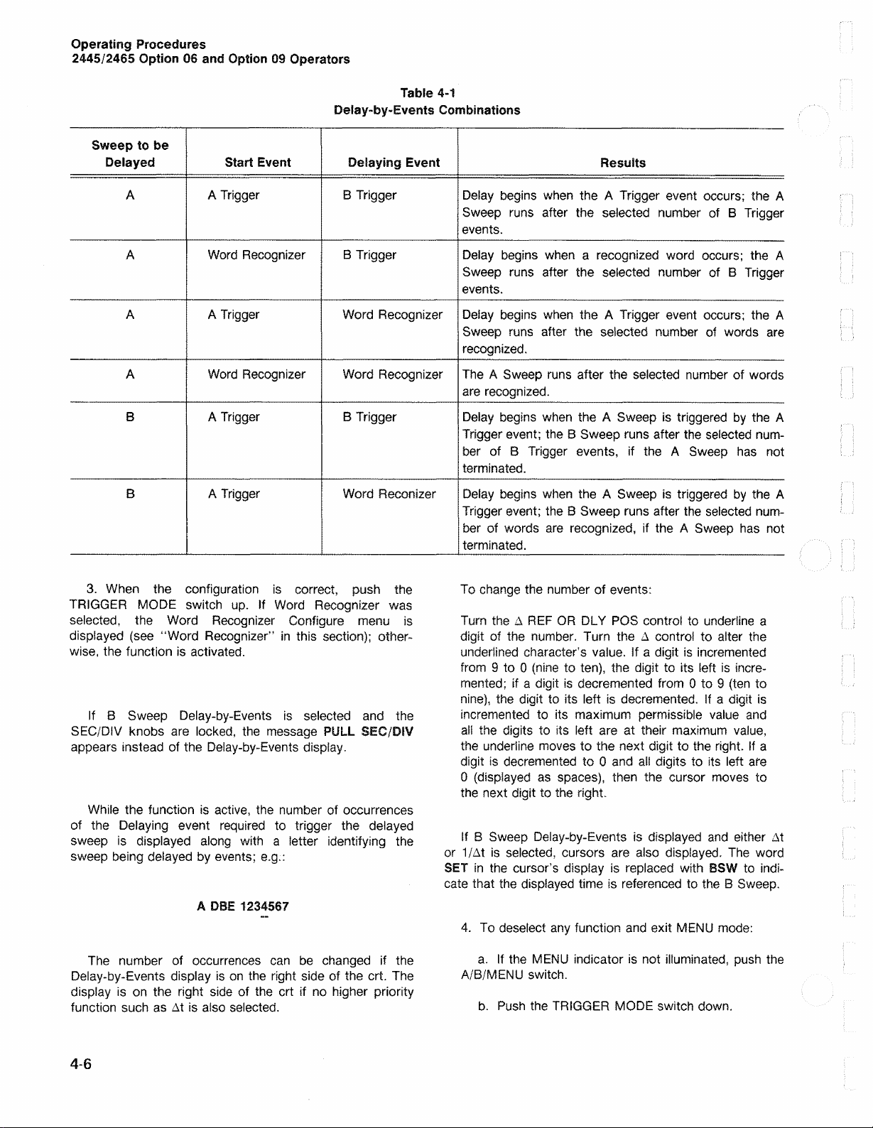
2445 /2465 Option 06 and Option 09 Operators
Delay-by-Events Combinations
Sweep to be
Delayed Start Event Delaying Event
Table 4-1
Results
A
A Trigge r
A Wo r d Recogniz e r
B Trigger
B Trigger
A A Trigge r Word Recognizer
A Wo r d Recognize r Word Recogniz er
B A Trigge r
B
A Trigg er
B Trigger
Word Reconize r
3. Wh e n the configuration is correct, push the
TRIG GER MODE switch up. If Word Recognizer was
selec te d , the Word Recog n izer Configure menu is
dispiayed (se e “Word Recognize r” in this section); other
wise, the function is activa te d .
If B Swe e p Delay-b y -E v e n ts is sele c ted and the
SEC/DIV knobs are loc k e d, the messa ge PUL L SEC/DIV
appear s instead of the Delay- b y -Events display .
Wh i le the function is activ e , the num b e r of occurrences
of the Delaying event req uired to trigger the delayed
sweep is displayed alo n g with a letter identifying th e
sweep bein g delayed by events; e.g.:
A DBE 1234567
Delay begin s whe n the A Trigger event occurs; the A
Swee p runs after the selected num b e r of B Trigger
even ts.
De lay begins when a recog niz e d word occurs; the A
Swee p runs after the selected number of B Trigge r
even ts .
De lay beg i n s when the A Trigger event occurs; the A
Swee p runs after the selected numbe r of words are
reco g n iz e d .
The A Sweep runs after the selec ted numb e r of words
are recogni z e d .
Delay beg in s when the A Swee p is triggered by the A
Trigger eve n t; the B Sweep runs after the selected num
ber of B Trigger events, if the A Sweep has not
termin a te d .
Delay beg in s when the A Swee p is triggere d by the A
Trigger event; the B Sweep runs after the select e d num
ber of words are rec og nize d , if the A Sw ee p ha s not
termina te d.
To chan g e the numbe r of events:
Tur n the Δ REF OR DL Y POS control to u n derline a
digit of the number. Turn the Δ control to alte r the
und e rl in ed character’s value. If a digit is inc r e mente d
from 9 to 0 (n i ne to ten ) , the digit to its left is incre
men t e d ; if a digit is decremente d from 0 to 9 (ten to
ni ne), the digit to its left is decrem e nted. If a digit is
incre mente d to its maximum perm is s ib le va l u e and
all the digits to its left are at their maxim u m val ue,
the unde r l ine move s to the next digit to the right. If a
digit is decremented to 0 an d al! digits to its left ar e
0 (dispia y e d as sp a c e s), then the cursor moves to
the next digit to the right.
If B Swe ep Delay-b y- Ev e nts is display e d an d either At
or 1/At is sele c t e d , cursors are also displa y ed . Th e word
SE T in the cursor’s display is repla c e d with BSW to ind i
cate that the displaye d time is refer e n c e d to the B Sweep.
4. To deselec t any function and exit MENU mod e:
The number of occurrence s can be chang ed if the
Delay-by-Ev ent s display is on the right side of the crt. The
display is on the right side of the crt if no higher priority
function such as At is also selec ted.
4-6
a. If the MENU indicator is not illu m inated, pus h the
A/B/MEN U switch.
b. Pu sh the TRIGG ER MODE switch down.
Page 29

2445/2465 Option 06 and Option 09 Operators
Operating Pr ocedures
If the A Sweep is delayed by events, selecting AUTO or
AUT O LVL Trig ge r Mode for the A Trigger will deselec t
Delay-by -E ve nt s and display the Mai n me nu.
NOTE
When the time between the start event and the
delaying event is less than 4 ns, whether or not the
delaying event will be counted is ambiguous. In
most cases, the ambiguity can be resolved by
choosing appropriate trigger slopes for the start and
delaying events.
Logic Trigger
To activate the Logic Trigger function from the Main
menu:
1. After using a delta control to underline LOGIC-TRIG
in the M a i n m enu an d pus h ing the TRIG GER M ODE
switch up, the Logi c-T rig ger -C o nfig ur e menu will be
displaye d . If the instrume n t contains the Word Recog n iz er
Option, the Logi c -T rig g er-C o nfig ur e menu is:
SWP:TRIG <A:A*B A:A+B A:WR B:WR>
The sweep (SWP) to b e trigge re d and the sou rc e
(TR IG) of the trigger are both selec te d from this menu . The
selections are:
are limite d to the capabilities of the 2445 or 24 6 5 without
the C/T/T Option.
If the instrument does not contain the Word Recognizer
Option, the Logic-Trigger-Configu re men u is:
TRIG A SWEEP BY <A B A + B>
2. Tu r n either delta control to move the unde r li n e cur
sor to the desire d selectio n .
3. W hen the configuration is correct, push the
TRIGGER MOD E switch up. If Wor d Reco g n iz e r has been
sele c te d , the Word-Recog nize r- Con fig ur at ion menu is
displayed (s ee “Word Recognizer” in this section); other
wise, the function is activate d .
If the Word Recogniz e r is selected in Logic-Trigger
mo d e, th e Word Recogniz e r dispiay takes the pla ce of the
respectiv e trigger-level display.
Whi le a Logic-Trigger function other than WR is active,
one of the following Logic-T rig g er displays is normally
displaye d on the right half of the crt re adou t. It is
displayed on the left half of the crt readout if a delta or
delay function is also active:
A SWP A’B and A SWP A + B
A:A*B = Th e A Sweep is triggered when the lo gical
AN D of the A and B Triggers becomes
TR UE.
A:A+B = The A Swee p is triggered wh e n the logical
O R of the A and B Triggers be c ome s
TR UE.
A:WR = The A Sweep is triggered when the Word
Rec ognizer detects the selecte d word,
B:WR = The B Sweep is triggered when the Word
Rec o g n iz e r detects the selected word.
NOTE
The trigger is TRUE if + SLOPE is selected and the
trigger-source voltage is more positive than the
trigger level, or if — SLOPE is selected and the
trigger-source voltage is more negative than the
trigger level·
When the B Swee p is triggere d by the Wor d Re c og
niz e r , delay time and delta time are measu re d by the
crystal-controlled time r , but w h en any other Logic-Trigg e r
function is active, delay -ti m e and delta-time measure ments
4. To deselect any function an d exit MEN U mo de:
a . If the MENU indicator is not illumina ted, push the
A/B/MENU switch.
b. Push the TRIGGER MODE switch down.
Seie c ti n g AUTO LVL A Trigger Mode while any Logic
Trigger function other than B Sweep triggered by the
Word Recognizer (B:WR) is active results in the function
bei n g deselecte d and the M ain menu b eing disp layed.
Resolution Selection
Fou r resolutions are availa b l e for Delay Tim e, D ei ta
Tim e, and 1/Delta Tim e p re c i s io n me a s u r e ments. In
AUTO , the display update rate is either eve r y 1/2 second
or every time a mea su r ement sample is availa b l e, which
ever is greater. For 1 ns, 10 0 ps , and 10 ps resolution,
the display is updated only whe n en o u g h swe e ps have
occurred to display the indicated resoluti on . For low sweep
repetition rates, the time interval betwe e n updates is
noticeably long. Table 4-2 lists the dispiayed resolutio n for
each resolutio n selectio n and the numbe r of swe e ps (N)
requir e d for eac h mea s u r e m e n t .
4-7
Page 30

Operating Procedures
24 45/2465 Option 06 and Option 09 Operators
Table 4-2
Resolution Selections
A SEC/DIV8 Selected Resolution
1 0 ns to 1 s
AU TO See AUTO RESOL U T ION
10 ns to 5 μ ε 10 ps
100 ps
1 ns
10 μ ε to 50 με
10 ps or 100 ps 10 0 ps
1 ns
10 0 MS to 50 0 μ5
1 ms to 5 ms
1 0 ps to 1 ns
1 0 ps to 1 ns
10 ms to 50 m s 10 ps to 1 ns
10 0 ms to 500 ms 10 ps to 1 ns
1 s
A SEC/DIV8 Trigger Repetition Rate
10 ns to 2 μ8
10 ns to 2 ^s
5 ms to 200 ms
10 ns to 200 ms
500 ms to 5 m s
1 0 ps to 1 ns
>20kHz
20 0 Hz to 20 kHz
>200 Hz
<200 Hz
An y
10 ms to 50 m s Any
10 0 ms to 500 m s
1 s
Any
Any
AUTO RESOLUTION
LSD
N
See AUTO RES OLUTION
10 ps >106
10 0 ps
1 ns
>104
>100
>104
1 ns
1 n s
>100
>100
10 n s >1
10 0 ns
>1
1 μ8 >1
10 μ 5 >1
LSD
N
10 0 ps >104
1 ns >100
1 ns
>100
10 ns >1
10 ns >1
10 0 ns
1 M$
>1
>1
10 MS >1
a2445 A SEC /D IV settings range from 20 ns to 1 s, 2465 A SEC/DI V settings range from 10 ns to 500 ms .
To activate the Resolution Selection function from
the Main menu:
menu function and the TR I GGER MOD E switch is pus h ed
up to exit the Function-Configurat ion me n u, the Word-
Recognizer-C onfigur atio n menu is display ed :
1. After usi ng either delta control to underline RES in
the Main men u and push in g the TR I GGER MODE switch
up , the Resolution Selec ti o n menu is displa ye d :
RESOLUTION <AUTO 1ns 100ps 10ps>
RADIX<BIN OCT HEX> CLOCK< t i X>
The Wor d Recognizer’s configuration is display e d in the
radix selecte d from the RADIX field. The cho i c e s are
2. Tur n either delta control to under li n e the des ir e d
binary (BIN ), octal (OCT), an d hexa d ecimal (H EX).
resolutio n.
The clock edg e, u s ed to acq u i r e data in the Word
3. P ush the TRIGGER MODE switch up when the
configuration is correct.
Word Recognizer Configuration
The Word-Recogniz er -C on fig urat io n menu is used to
Recognize r , is selected from the clock field. The cho ic e s
are:
τ = rising edge of clock,
i = fall i n g edg e of clock.
set the Word Recogniz er ’s radix and clock paramet ers .
Wh e n Word Reco g n iz e r (W R) is selecte d for use by a
X = n o clock used (asynchron o u s mode).
4-8
Page 31

2445/2465 Option 06 and Option 09 Operators
Operating Procedures
To set the Word Recogn izer ’s parameters:
1 . S e lect the Word Recognizer in a Func tio n -
Configuration me nu.
2. Exit the function’s men u by pushing up on the
TRIGGER M ODE switc h . The Word-Recog ni zer -
Configuration me nu is then disp la ye d .
3. Turn the Δ REF OR DL Y POS control to un d erline
the field to be configured (i.e., RADIX or CLOCK). Tu r n the
Δ control to unde r l in e the selectio n for that fiel d .
4. Wh en the configuration is correct, push the
TRIGGER MODE switch up to activate the function.
Wh en a m enu function uses the Word Recogniz er, the
status of the Wor d Recogniz e r is displayed in the following
format:
tcq word
The t is the trigger sele c te d (A or B); the c is the clock
mo d e, risin g (t) or fallin g (!) edg e , or asynchr on ou s (X);
the q is the qualifier bit; and ‘word’ is a value display e d in
the selected radix.
been defined usin g the C/T /T m e nu. The sign a l remains
valid ev e n if the men u function is not in use. The relation
of the word coin c idence relative to other signals can be
observe d by connec tin g the WORD OUT signal to one
vertical chann el and us ing the remaining vertical channels
for the other signa ls .
The WORD OUT signa l is delaye d after the clock tran
sition in synchronou s mode or after the recogniz e d coin
cide n c e in asynch ro nou s mo d e. Bec a use of this delay, the
sign a l transition which generate s the trigger cannot be
displaye d by the oscillosc ope when the oscilloscope is trig
gered by the Word Recogn i z e r or when the oscilloscope is
triggered by the WOR D OU T sign a l .
CONTROLLING INSTRUMENT FUNCTIONS
WITH THE GPIB
This information pertains to controlling the 2445 an d
246 5 Oscilloscopes containing Counter/Timer/Trigge r
(Option 06 ) , or the Counter/Timer/Trigger with the Wor d
Recogn iz e r (Option 09) via the IEEE - 4 8 8 - 1 9 78 digital inter
face (commonly referr e d to as the G enera l Purpose Inter
face Bus, or GPIB ) . Th is informati on applie s only if the
instrument also contains the GPIB (Option 10) interface.
The Δ REF OR DL Y P OS control is turned to unde r l in e
the clock mo de, qualifier, or a digit of the word. The Δ con
trol cha nge s the selection for the underli n ed field .
If some bits of a hexadecima l or octal digit are
irreleva n t (don’t care or ‘X’) the digit is ambiguous. Ambig
uous digits are displaye d as question marks; e.g.:
ATQ11XXXXX1 ATO 1?X077 A TO ??3F
... 001 1 1111
BIN O CT H EX
When the status of the Word Recognizer and the even t
count for De l a y -b y - E v e n ts a r e both dispiayed, the Δ REF
OR DLY P OS control will move the selection cursor acro ss
both fields.
WORD OUT SIGNAL
Th e WORD OUT signal, at a BNC connector on the
rear pa nel, is high when th e selecte d word is reco gnize d.
This signa l is vali d after the Word Recogn ize r word ha s
NOTE
If either the Counter/Timer/Trigger or Word Recog
nizer option is not contained in the instrument, refer
ence to it in a GPIB command will cause an SRQ
error,
The 2445/2465 Optio n 10 GPI B Operators Manual
should be consulted for a comple te description of remote
control of oscilloscope functions by way of the GPIB.
A complete description of additional command s for con
trolling the Counter/Timer/T rigge r Option an d the
Counter/Timer/Trigger with the Wor d Rec o g n i z e r Option is
listed in Table 4-3 and Table 4-4 respec ti v ely .
NOTE
C/T/T measurements are requested with the CTSend
command. DELAy? and DTIme? queries, which are
common to the 2445/2465 without the C/T/T Option,
return settings, not measurements.
4-9
Page 32

Operating Procedures
244 5/24 65 Option 06 and Option 09 Operato rs
Counter/Timer/Trigger GPIB Commands
C/T/T Measurement Commands
Table 4-3
Header
CTR d y ?
CTSend?
Argument
IM Mediate
WA tt
Argument Comments
Quer y response is 1 if a C/T/T measur e m e n t is available, 0 if
not. This flag is always vali d rega rd le s s of the OPC state. If no
meas u re m e n t function is active, or a measu r e m e n t function is
susp e n d e d due to another option using the display , an option-
not-in-correct-mode SRQ error is sent.
This command is us ed to request any one of the following
measure m en ts ; FREQ u e ncy, PER sod , TGTaiize, De l ay, Delta
Time , or 1/Delta Time. The meas u r e m e n t returne d is that
genera te d by the currently operating function. The format of
the returned measurment is <nr3>. The “?” following CTSend
is optional and does not affect the operation of the command .
If the currently available meas u r ement is inv alid, an error co d e
is returned in place of the norm al mea s u r e ment. The error
code s are:
I.OE+99 for a miss ing B trigge r.
I.OE+98 for a miss ing A trigger.
I.OE+97 when the time being me asur ed in a MM
mode is less than 1 % of full sca l e.
t.OE+96 for Totalize mode overflow.
Sf no measurem en t function (count, precis io n delta, or delay) is
active, or a measurem en t fu nc tio n is suspend e d due to another
option using the display, an option-is-not-in-correct-mode SRQ
error is sent.
Any given measurement is onl y sent once. Th e current
meas ur e m e nt is always sent immedia tely if it has not already
be en sen t once.
The argument following CTSe nd controls the manne r in which
the instrument responds when a mea s u r e m e n t is in progress
and no current measu r e m en t is availab l e to sen d. CTSend with
no argument defaults to WAI t for a mea s u r e ment. If a
meas ur e m e nt is not ava i la ble an d the IMMed ia te argument is
rece iv ed, a null messag e (talke d with nothing to say) is sent. If
a measuremen t is not availab l e and the IMMediate argument is
not rece iv e d, the instrument will not respon d until a new
meas ur e m e nt has bee n acqu i red.
4-10
Page 33
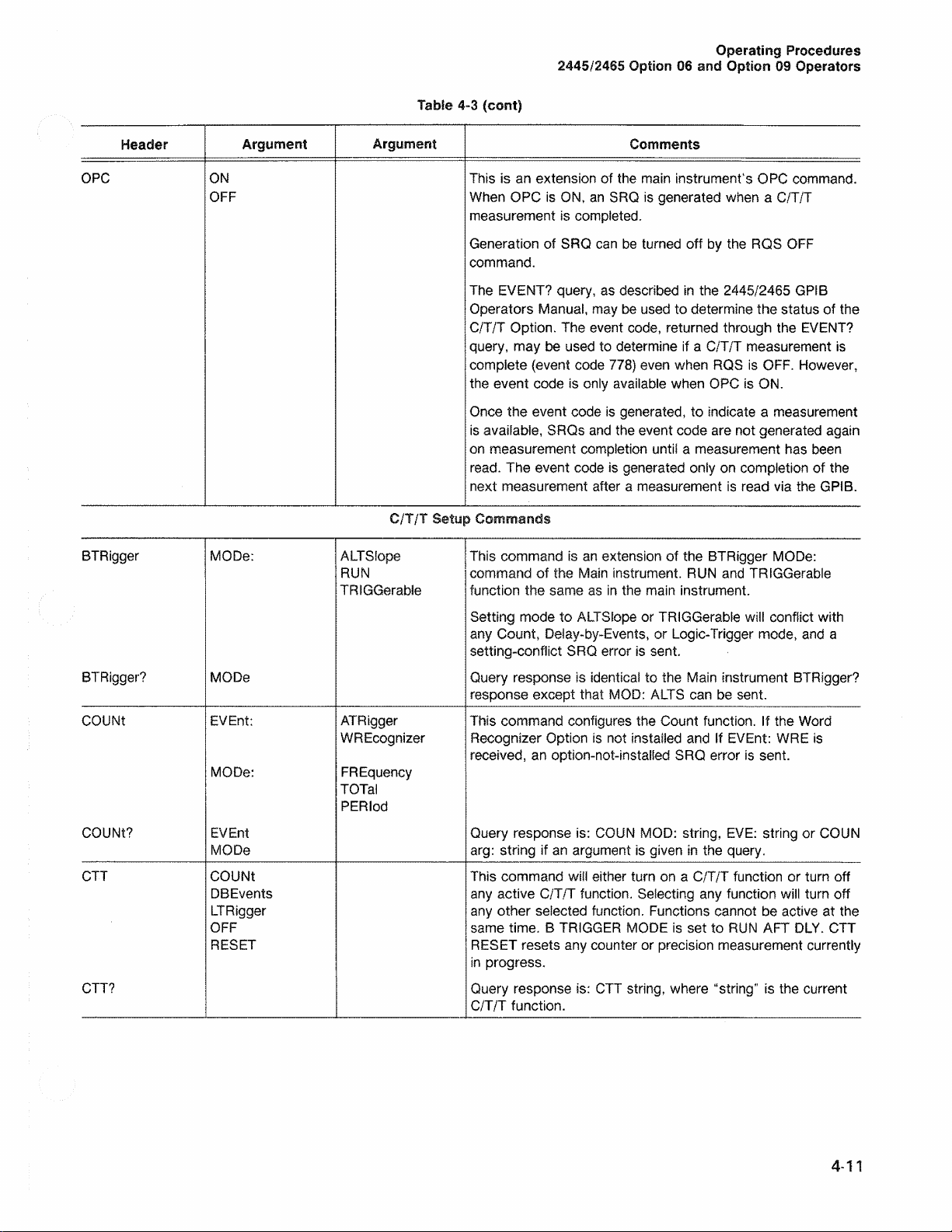
Table 4-3 (co nt)
2445/2465 Option 06 and Option 09 Ope rators
Operati ng Procedures
Header Argument
O PC
O N
O FF
BTRigger
MODe: AL T Sfope
BT Rigger? MODe
CO UNt EVEn t :
MODe:
COUNt ? EVEnt
MODe
CTT C O UNt
DBEv e n ts
LTRigger
OFF
RE SET
CTT?
Argument
C/T/T Setup Commands
R UN
TRIG Gerabie
ATR i g g e r
WREco g n iz er
FR Equenc y
TOTal
PERiod
Comments
This is an extension of the main instrument’s OPC command.
Wh en OPC is ON, a n SRQ is generated when a C/T/T
measurem en t is com p le ted.
Generatio n of SRQ ca n be turned off by the RQ S OF F
comm a n d.
The EVE NT? query, as descri b e d in the 2445/2465 GPIB
Operators Ma n u a l, may be used to determine the status of the
C/T/T Option. The event code, returne d through the EVENT?
query , may be used to determin e if a C/T/T measu re m e n t is
complete (event cod e 778 ) even when RQS is OFF . Howe v er,
the event code is onl y availa b le when OPC is ON.
Once the event code is generated , to indicate a meas u r e m e n t
is availabl e, SRQ s an d the event code are not generate d agai n
on measurement completio n until a measu re m e n t has been
read. The event code is generated only on completion of the
next measuremen t after a measu re m e n t is read via the GPIB.
This command is an extension of the BTRigger MO De:
comman d of the Mai n instrument . RU N and TRIGGera b i e
function the sam e as in the mai n instrument.
Setting mo de to ALTS I ope or TRIG G e rabie will conflict with
any Count, Delay-b y - E v e n ts , or Logic- T rigg er mode, and a
setting-conflict SR Q error is sent.
Quer y response is identi c a l to the Main instrument BTRigger?
response except that MO D: ALTS can be sent.
This command configu re s the Count functio n . If the Word
Recognizer Option is not installed and If EVEnt: WRE is
receiv e d , an option-not-installed SRQ error is sent.
Query response is: COUN MOD: string, EV E: string or COUN
arg: string if an argume n t is given in the que r y .
This command will either turn on a C/T/T function or turn off
any active C/T/T function. Selec ti ng any function will turn off
any other sele cted func tio n. Functions cannot be active at the
sam e time. B TRIGGER MODE is set to RUN AFT DL Y. CT T
RES E T resets any counte r or precision measurement currently
in progress.
Que ry response is: CTT string, where “string” is the current
C/T/T function.
4-11
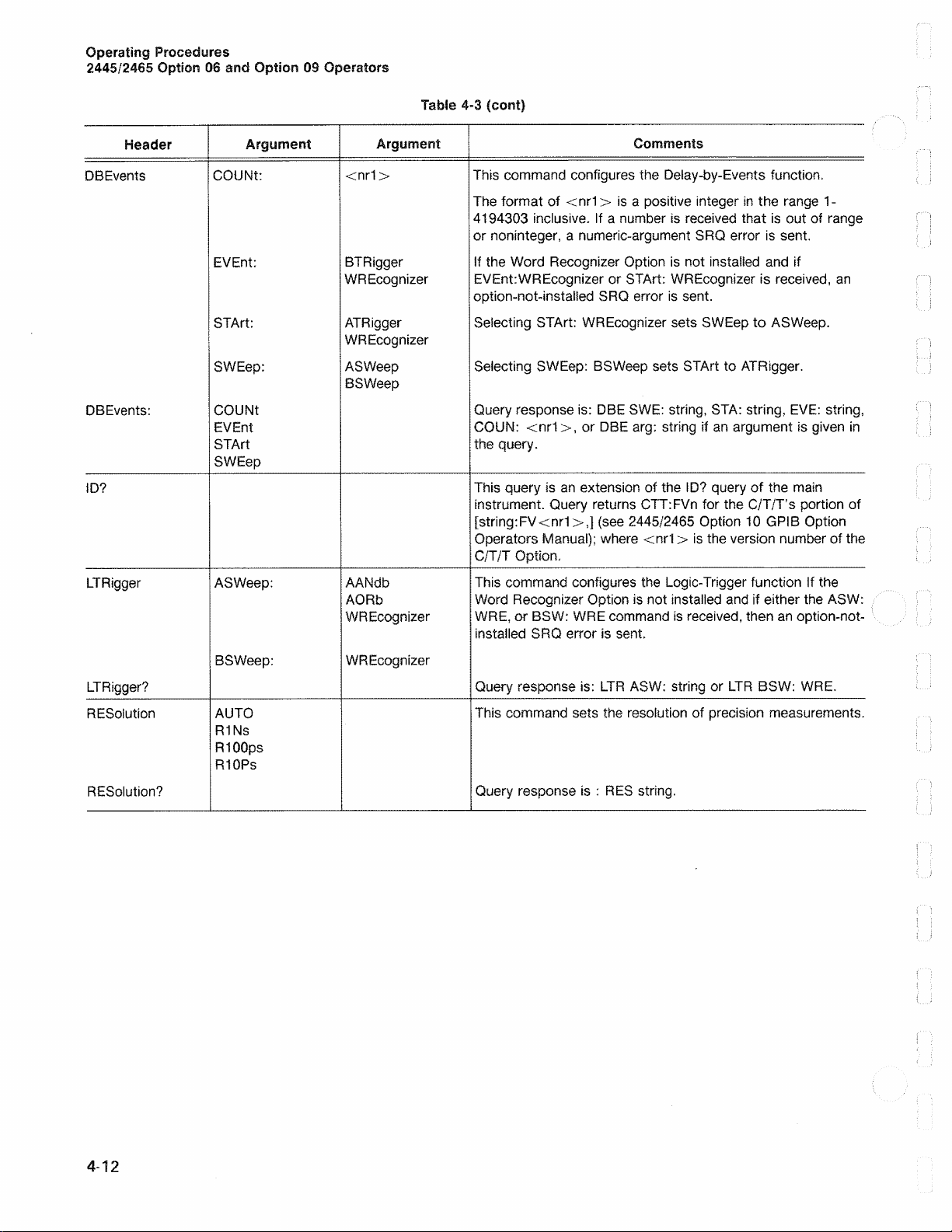
Page 34
Operating Procedures
244 5/24 65 Option 06 and Option 09 Operators
Table 4-3 (cont)
Header
DBEvents
Argument
COUN t:
EV E n t:
STAr t: ATRi g ger
SWEe p :
DB E v ents:
COUN t
EVE n t
STA r t
SW Eep
ID?
LT Rigge r AS Weep:
BS Weep:
LTRigger?
RE S olution
AU T O
R1 Ns
R100p s
R1 0 Ps
RE Solu ti o n ?
Argument
Comments
<nr1> This command configure s the Delay-by -E v e n ts function.
The format of <nr1> is a positive integer in the rang e 1-
4194303 inclusiv e . If a num b e r is receiv e d that is out of range
or noninteger, a nume r ic -a rg u m e n t SRQ error is sent.
BTR igger
WRE c o gn iz e r
If the Word Reco g n iz e r Option is not installe d and if
EVEnt:WREcogniz er or STArt: WRE co g n iz er is receive d , an
option-not-instalied SRQ error is sent.
Seiecting STArt: WREc o g nizer sets SWE e p to AS W eep.
WREcognizer
AS Weep
Selecting SWEep : BSWeep sets STArt to ATRig g e r .
BS Weep
Quer y response is: DB E SWE: string, STA : string, EV E: strin g ,
COUN: <nr1>, or DBE arg: string if an argument is give n in
the query.
This query is an extension of the ID ? quer y of the m ain
instrument. Query returns CTT:FV n for the C/T/T’s portion of
[string:FV<nr1>,] (see 2445/24 65 Option 10 GPIB Option
Operators Man u a l) ; where <nr1 > is the version number of th e
C/T/T Option,
AANd b
AORb
WRE c o gn iz e r
This command configures the Logic - Tri g ge r function If the
Word Recognizer Option is not insta l le d and if either the ASW:
WR E , or BSW: WR E command is received, then an option-not-
installe d SRQ error is sent.
WRE c o g n i z e r
Quer y response is: L TR ASW : string or LTR BSW: WR E.
This command sets the resolution of pre cis ion measur e m e n t s .
Quer y response is : RES string.
4-12
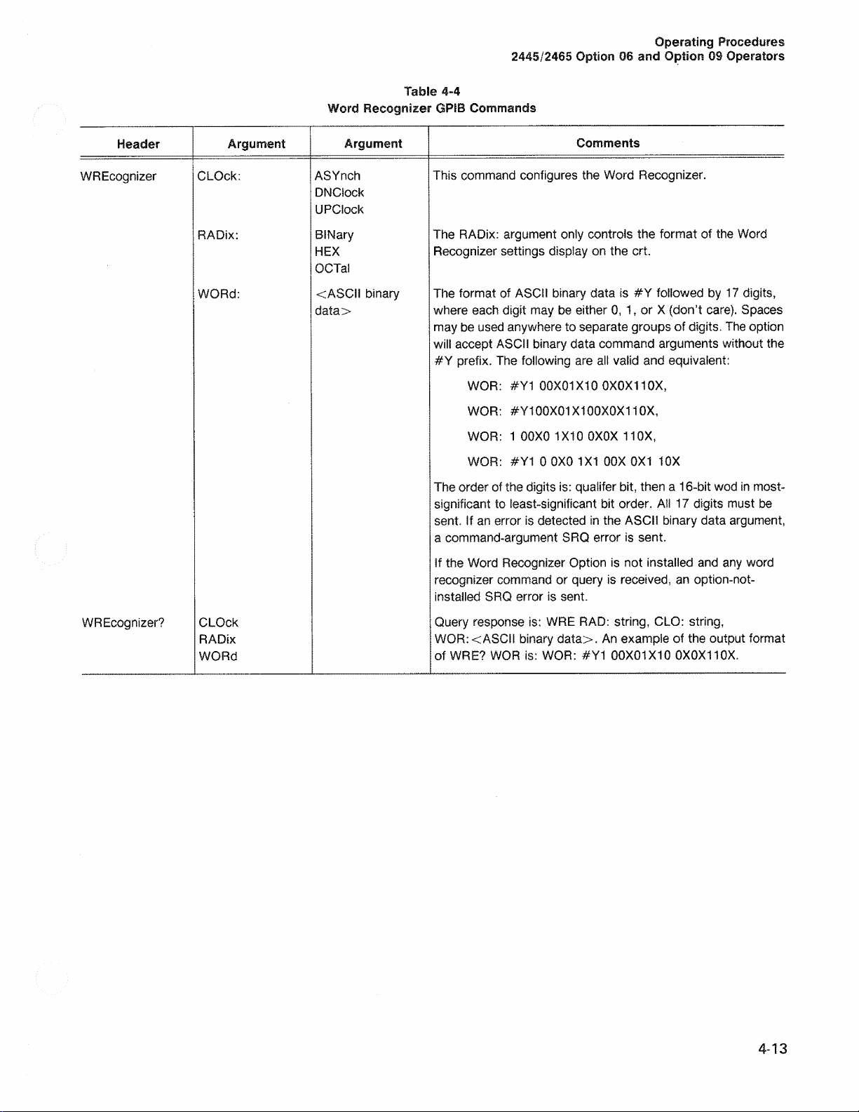
Page 35
244 5/24 65 Option 06 and Option 09 Operators
Ta foSe 4-4
Word Recognizer GPIB Commands
Operating Procedures
Header
WREco g n iz er
Argument
CLOck:
RADix:
WOR d:
Argument
ASYn c h
DNCSock
UPC io c k
BiNary
HEX
OCTal
<ASCii binar y
data>
Comments
This comman d configur es the Word Recogniz e r.
The RADix: argument only controls the format of the Word
Recog n ize r settings displa y on the crt.
The format of ASCI I bina r y data is #Y followed by 17 digits,
where each digit may be either 0, 1, or X (don’t care). Spa c es
ma y b e u sed anywhere to sepa r ate groups of digits. The option
will accept ASC I I binary data comman d arguments without the
#Y prefix. The following are all valid and equivalent:
WOR: #Y1 00X 0 1X10 0X0X110X,
WOR: #Y100X01X100X0X110X,
WO R : 1 00X0 1X 1 0 0 Χ0 Χ 11 O X,
WO R : #Y1 0 0X0 1X1 00X 0X 1 10X
The order of the digits is: qualifer bit, then a 16-bit wod in most-
significant to least-significant bit order. Al l 17 digits must be
sent. If an error is detect e d in the ASCII binary data argument,
a command-a rg u m e nt SRQ error is sent.
WREcognizer?
CLOck
RADix
WORd
If the Word Reco g n iz e r Option is not installed and any word
recognizer com mand or query is receive d, an option-not-
instalie d SRQ error is sent.
Que ry respons e is: WRE RA D: string, CLO: string,
WOR : < AS C I I bina r y data>. An example of the output format
of WRE? WOR is: W O R: #Y1 00X01X10 0X0X110X.
4-13
Page 36

Page 37
2445/2465 Option 06 and Option 09 Operators
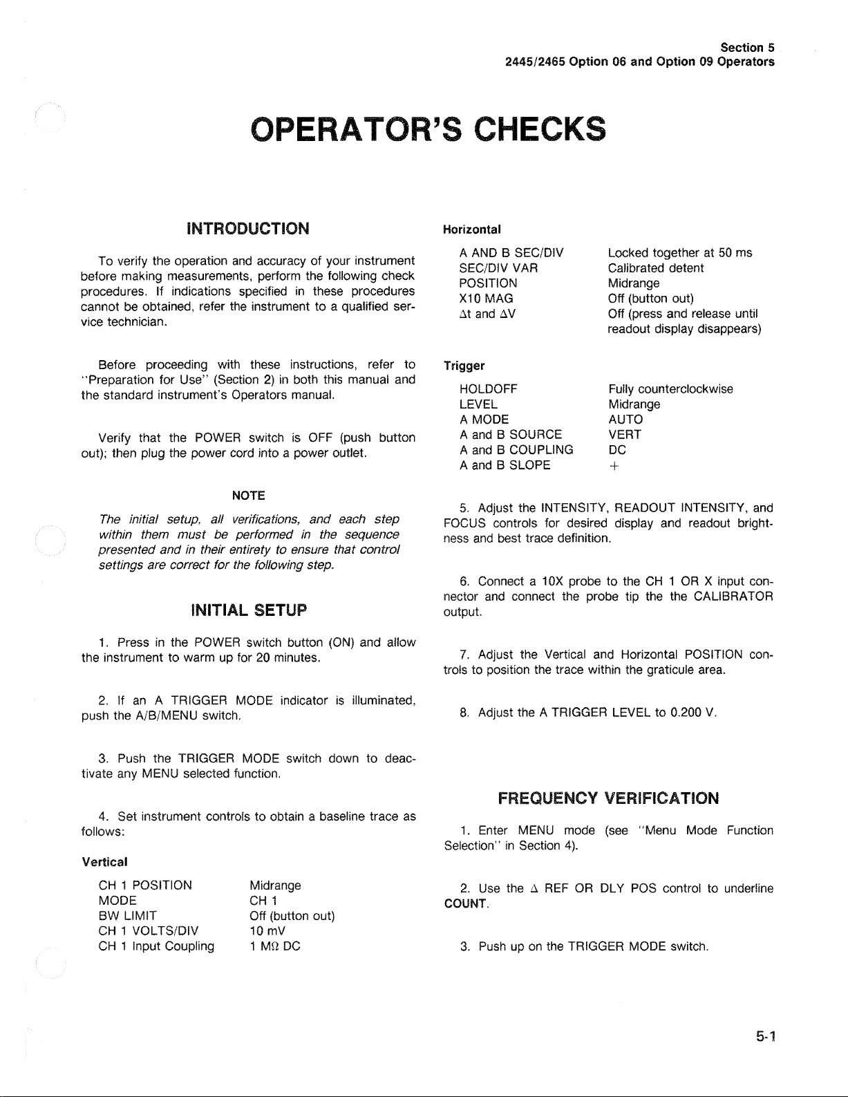
OPERATOR’S CHECKS
Section 5
INTRODUCTION
To verify the operation and accu racy of your instrument
before making meas ur e m e nt s , perform the following check
procedures. If indications speci fi e d in these procedures
cannot be obtained, refer the instrum ent to a qualified ser
vice technician.
Before proceeding with thes e instructions, refer to
“ Preparation for Use” (Sect io n 2) in both this manu al and
the standard instrument’s Operators man ual.
Verify that the POWER switch is OFF (push button
out); then plug the power cor d into a power outlet.
NOTE
The initial setup, all verifications, and each step
within them must be performed in the sequence
presented and in their entirety to ensure that control
settings are correct for the following step.
INITIAL SETUP
Horizontal
A AND B SEC/ D iV
SEC/DIV VAR
PO SITION
X10 M AG
At and AV
Trigger
HO L DOFF
LEVEL
A MOD E
A and B SOURCE
A and B CO UPLING
A and B SLO P E
5. Adjust the INTENSITY , READ O UT INTENSITY , and
FOCUS controls for desired display an d reado u t bright
ne ss and best trace definition.
6 . Connect a 10X probe to the CH 1 OR X input con
nector and connect the probe tip the the CALIBR A T O R
output.
Lock e d together at 50 ms
Calibra te d detent
Midra n g e
Off (button out)
Off (pres s and release until
readout display disappe a r s )
Fu l l y counterclockw ise
Midr an g e
AU TO
VERT
D C
+
1 . Pre s s in the POWER switch button (O N) and allow
the instrument to warm up for 20 minute s .
2. If an A TRIGGER MODE indicator is illuminated,
push the A/B/MENU switch.
3. Pu sh the TRIGGE R MODE switch down to deac
tivate any MENU selected function.
4. Set instrument controls to obtain a base li n e trace as
follows:
Vertical
CH 1 POSIT IO N
MOD E
BW LIMIT
CH 1 VOLTS/DIV
CH 1 Input Coupling
Mid ra n g e
C H 1
Off (button out)
10 m V
1 Μ Ω DC
7. Adjust the Vertic al and Horizonta l POSITION con
trols to position the trace within the graticule area .
8 . Adjust the A TRIGGER LE V EL to 0.200 V.
FREQUENCY VERIFICATION
1. Enter MENU mod e (see “ Menu Mode F u nction
Selection” in Section 4 ).
2 . Use the A REF OR DLY P OS control to underlin e
COUNT.
3 . Pus h up on the TRIGGER MODE switch.
5-1
Page 38

Operator’s Checks
2445/2465 Option 06 and Option 09 Operators
4. Use the Δ REF OR DLY PO S control to unde r lin e
MODE.
5. Use the Δ control to underlin e FREQ .
6. If the instrument co nta in s the Word Reco gn iz er
Option:
a . Us e the Δ RE F OR DLY POS control to underline
EVT.
b. Use the Δ control to und e r l in e A.
7. Pus h up on the TRIGGER MOD E switch.
8. Verify the displayed frequenc y is between 9.99 Hz
an d 10 . 01 H z.
9. Exit Menu mode (see “Men u Mode Func ti o n Selec
tion” in Section 4).
DELTA VERIFICATION
1 . Select the delta time mode using the At switch.
2. Move the intensified zone as far left as pos s i b le
usin g the Δ REF OR DLY POS control.
3. Move the secon d intensified zone two divisio n s to
the right of the first intensifie d zone usin g the Δ control.
4. Verify the displa ye d delta time is betwe en 999 . 0 ns
and 1001. 0 ns.
5. Des elec t the delta time mode using the At switc h .
6. Lock together the A AND B SEC/D I V switch.
DELAY-BY-EVENTS
1 . Set the A TRIG GER SLO PE to
DELAY VERIFICATION
1 . Selec t AUTO Reso lu tio n (se e “ Resolution Selection”
in Section 4).
2. Set the A AND B SEC / D I V switches to 0.5 m S.
3. Puil out the B SEC/D IV switch.
4. Set the B TRIGG E R MODE to TRIG AFT DLY.
5. Adjust the B TRIGGER LE VEL to 0.200 V.
6. Move the intensified zone as far left as possible
usi n g the Δ REF OR DL Y POS control.
7. Verify the display ed deiay is between 989.5 ns and
101 0 .5 ns.
2. Ente r Menu mod e.
3. U se the A REF OR DL Y POS control to underline
DLY/EVTS.
4. Pu s h up on the TRIGG E R MODE switch.
5. Use the A REF OR DLY POS and A controls to
selec t SWP B, START A, DLY BY B (see “ Dela y - by-
Events” in Section 4 ).
6 . P ush up on the TRIGG ER MO DE switch.
7. Pu l l out the B SEC/DIV switch.
8. Use the A REF OR DL Y POS and the A controls to
set the nu m b e r of delaying events to 1.
9. Verify that the intensified zone moves to each
succ e e ding risin g edge as the delaying event count is
chan g e d to 2, 3, 4, and 5.
5-2
Page 39
2445/2465 Option 06 and Option 09 Operators
OPTIO NS AND ACCESSORIES
Section 6
INTROD UC TION
This section contains a ge n e r al description of instru
ment options available at the time of publication of this
manu a l. Also included is a com p le te list (with Tektronix
part num b e rs ) of standard acce s s o r ie s included with each
instrument. Addition a l information about instrument
options, option avai la bility , and other access ories can be
obtained either by con s ult in g the current Tektronix Product
Catalog or by contacting your local Tektronix Field Off ice
or representative.
OPTIONS
There are currently no options available for the C/T/T
and WR. Also , Option 11 (rear panel probe-power connec
tors) describ ed in th e 2465 manua l s and Option 09 (Word
Recogn iz e r) des c r ibed in this man ual are not availab le in
the same instru ment.
Description Part Number
2445/2 4 65 Option 06 an d Optio n 09 0 7 0 -4 6 3 1 - 0 0
Counter/Timer/Trigger an d
Word Recognizer Operators Manual
2445/246 5 Option 06 and Opt io n 09 0 7 0 -4 181-0 0
Counter/Timer/Trigger an d
Word Recogn iz er Reference Card
2445/2 46 5 Option 06 and Optio n 09 070-53 6 6 - 00
Counter/Timer/ T rigger and
Word Recogn iz e r Referen c e Guid e
Ea ch instrument containing the Word Reco gnize r is pro
vide d with the following standa rd acce ss o ries in additi o n to
those ment io n e d for the Counter/Tim er /T rigg e r:
1 P6407 Word Recognize r Probe 010-6407- 0 1
multi- le a d , with the
following accesso rie s :
2 10-wide comb, 10-i nch 012- 0 7 4 7 -0 0
lead s (without grabbe r s )
20 Grabber Tips 206- 0 2 2 2 -0 0
ACCESSORIES
In addition to the bas e instrument’s standard acces
sories, one e ach of the following stand a rd accessories is
provided with ea ch instrum e nt con tain ing the 2445/2465
Option 06 Counter/T im e r/T r ig ge r:
In addition to the base instrument’s optional acces
sories, the following optional access o r y is available for the
Counter/Timer/Trigger or the Count er /Timer/Trigge r and
Word Recogn iz e r options:
2445/2465 Option 06 and Opt i o n 09 0 70-4632-0 0
Counter/Timer/Trigger an d
Word Recognize r Servic e Ma nual
6-1
Page 40

Page 41

2445/2465 Option 06 and Option 09 Operators
APPENDIX A
GPIB COMMAND REFERENCE
Appendix A
Table A-1
Counter/Timer/Trigger GPIB Command Summary
C/T/T Measurement Commands
Header
CTR dy ?
CTS e n d ?
OPC
BTRigger
BTRigg e r?
COUNt EVe nt:
COUNt?
CT T CO U Nt
CT T ?
DBEve n ts COUNt: <nr1>
DBEv en ts ?
Argument Argument
IM Mediate
WAIt
O N
O FF
C/T/T Setup Commands
MODe: ALTS lope
RU N
TRIG G e ra b ie
MODe
ATRigger
WREcogn iz er
MODe: FREq u e n c y
TOTal
PERio d
EVEn t
MODe
DBE v e n ts
LTRigger
OFF
RE SET
EV Ent:
STArt: ATRigg e r
SW Eep: ASWeep
COUNt
EVEnt
STA rt
SW E ep
BTRigger
WREcognizer
WREcognizer
BSWe e p
Table A-1 (cont)
Header Argument Argument
LTR i g ger ASWeep: AANdb
AOR b
WRE c o gn iz e r
BSWeep:
LT Rigg er?
RESo lu tio n AUto
R1 Ns
R10 0 p s
R1 0Ps
RES olu ti o n ?
Table A-2
Word Recognizer GPIB Command Summary
Header
WREco g n iz er CLOck: ASY n c h
WRE c o g n iz e r?
Argument Argument
RADix : BIN a r y
WO R d : <ASCII binary
CLOck
RADix
WO Rd
WRE c o gn iz e r
DN CIock
UP CIock
HEX
OCTal
data>
A- 1
Page 42

Page 43

MANUAL CHANGE INFORMATION
At Tektronix, we continuaily strive to keep up with latest electronic developments
by adding circuit and component improvements to our instruments as soon as they
are developed and tested.
Sometimes, due to printing and shipping requirements, we can’t get these
changes immediately into printed manuals. Hence, your manual may contain new
change information on following pages.
A single change may affect several sections. Since the change information sheets
are carried in the manual until all changes are permanently entered, some
duplication may occur. If no such change pages appear following this page, your
manual is correct a s printed.
Page 44

 Loading...