

Page 1
070-6602-00
Product Group 37
2440
GPIB
POCKET GUIDE
Page 2

-
.
<
. . .--..e
-m.-.. .
TEK . INTER-OFFICE COMlvllJNlCATlON
TO
Sohn Martin
94-540
.-
3:. ’ t
.
Juno 25, 1991
Frank Gray, SO-PAT
FWW
M3KC.T
GIDEP permit request
In response to
Government
Tektronix operator,
Tektronix, Inc. hereby grant6 such permission for distribution
of
such documents to any
in the Metrology Data Interchange Data Base
that
copyright notice and ownership statement exactly a-& it appears
in the original, together with the Legend "Reproduded with
pemieeion,a
aeon% 1[
all copies
This permission has been approved by the Intellectual
Industry
Committee of Tektronix
ded
to GIDEP to grovide’the requested permission.
the request
Exchange
service and
GTDEP
of the original work include the entire
to grant permission to
Pro
ram (GPDEP) to reproduce
nstruction manuals,
P
user that is a full participant
of
GIDEP provided
and
a
copy of this memo may
the
geG&dy
Group Pat&t Counsel Group Patent C&nsal v
Page 3

Copyright ’
Contents of this publication may not be reproduced in an’
form without the written permission of Tektronix, Inc.
Products of Tektronix, Inc. and its subsidiaries are coverer
by U.S. and foreign patents and/or pending patents.
TEKTRONIX. TEK, SCOPE-MOBILE, and an
registered trademarks of Tektronix, Inc. TELEQUIPMENT i!
a registered trademark of Tektronix U.K. Limited.
Printed in U.S.A. Specification and price change priviledgel
are reserved.
1988
Tektronix, Inc. All rights reservec
INSTRUMENT SERIAL NUMBERS
Each instrument has a serial number on a panel insert, tag
or stamped on the chassis. The first number or letter
designates the country of manufacture. The last five digits
of the serial number are assigned sequentially and arc
unique to each instrument. Those manufactured in the
United states have six unique digits. The country o
manufacture is identified as follows:
BOO0000 Tektronix, Inc., Beaverton. Oregon, USA
100000
200000
300000
700000
Tektronix Guernsey, Ltd., Channel Islands
Tektronix United Kingdom, Ltd., London
Sony/Tektronix, Japan
Tektronix Holland, NV, Heerenveen,
The Netherlands
First Printing-March 1988
Page 4

CONTENTS
GPIB Command Reference
.....................
Page
l-l
Alphabetical GPIB Command Reference
Event Tables ................................
Character Charts
............................
..........
2-l
3-1
4-l
Page 5

INTRODUCTION
This guide contains two references of the GPIB
ommands listed in Appendix A of the Programmers
deference Guide included with the 2440. The first reference,
GPIB Command Reference,” sorts the commands
ccording to type: Vertical Commands, Horizontal
:ommands, etc.; the second reference, “Alphabetical GPIB
Fommand Reference,” according to the alphabetical order
f the commands. Both lists omit the descriptions for the
ommands-consult Appendix A of the Programmers
leference Guide for those descriptions.
Also included in this guide are the Event Codes and their
escriptions. These are codes which the 2440 issues over
ie GPIB that represent errors, warnings, and other
iessages of interest to System Programmers.
At the end of the guide are two charts. The first chart
hows the character set the 2440 displays. The second
hart shows ASCII symbols and their GPIB equivalents.
,ee the Programmers Reference Guide for information on
ow to use these charts.
,~” ..- .-- .___ -.--_L--_Il_
Page 6
GPIB Command Reference
GPIB Command
Reference
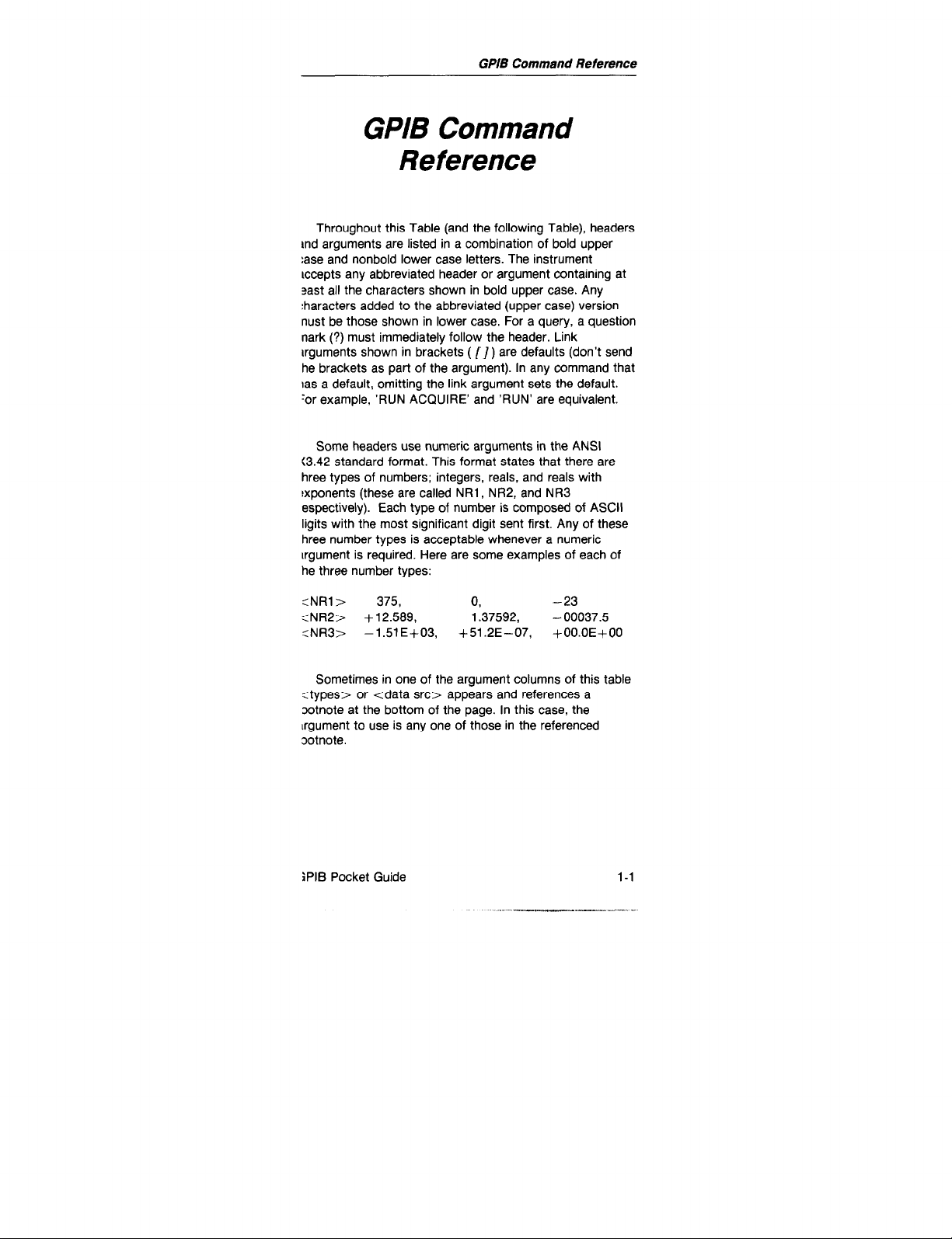
Throughout this Table (and the following Table), headers
md arguments are listed in a combination of bold upper
:ase and nonbold lower case letters. The instrument
accepts any abbreviated header or argument containing at
sast all the characters shown in bold upper case. Any
:haracters added to the abbreviated (upper case) version
nust be those shown in lower case. For a query, a question
nark (?) must immediately follow the header. Link
arguments shown in brackets ( [I) are defaults (don’t send
he brackets as part of the argument). In any command that
ras a default, omitting the link argument sets the default.
‘or example, ‘RUN ACQUIRE’ and ‘RUN’ are equivalent.
Some headers use numeric arguments in the ANSI
(3.42 standard format. This format states that there are
hree types of numbers; integers, reals, and reals with
exponents (these are called NRl, NR2, and NR3
espectively). Each type of number is composed of ASCII
ligits with the most significant digit sent first. Any of these
hree number types is acceptable whenever a numeric
argument is required. Here are some examples of each of
he three number types:
:NRl> 375,
:NR2> +12.589, 1.37592, - 00037.5
:NR3>
Sometimes in one of the argument columns of this table
<types> or <data src> appears and references a
ootnote at the bottom of the page. In this case, the
lrgument to use is any one of those in the referenced
ootnote.
jPlB Pocket Guide l-l
- 1.51 E+03, +51.2E-07, +OO.OE+OO
0,
-23
Page 7

GP/B Commend Reference
Vertical Commands
Header
CHl(or CH2)
PROBe?
BWLimit
VMOde
Argument
VoLts
VARiable
POSition
Coupling
FlFty
INVert
CHl
CH2
EXTl
EXTP
TWEnty
HUNdred
FULI
CHl
Argument
<NR3>
<NR3>
<NR3>
AC
DC
GND
WI
OFF
WI
OFF
WI
OFF
Argument
l-2
CH2
ADD
MULt
DlSPlay
WI
OFF
[ONI
OFF
WI
OFF
XY
YT
GPIB Pocket Guide
Page 8

Trigger Commands
Header
ATRigger
Argument
MODe
SOUrce
LOGsrc
Coupling
LEVel
Argument
AUTOLevel
AUTO
NORmal
SGLseq
CHl
CH2
LlNe
VERtical
EXTI
EXT2
WORd
A.B
OFF
AC
DC
LFRej
HFRej
NOlserej
TV
<NR3>
Argument
SLOpe
POSition
HOLdoff
ABSElect
MINImum
3PlB Pocket Guide
PLUS
MINUS
<NRl>
<NR3>
A
B
l-3
Page 9

GPIB Command Reference
Trigger Commands (cant)
Header
ATRigger
(cant)
INITAt50
Argument
MAXimum
STATe
CLRstate
MODe
EXTCLk
SOUrce
Coupling
Argument
RUNSaft
TRIgaft
WI
OFF
CHl
CH2
WORd
VERtical
EXTl
EXT2
AC
DC
LFRej
HFRej
NOlserej
Argument
l-4
LEVel
SLOpe
POSition
<NR3>
PLUS
MINUS
<NRl>
Page 10

GPh9 Command Reference
Trigger Commands (cant)
Header
ETTV
ETWord
ANtrig
<TGain
Argument
ICOupling
NlCoupling
INTERlaced
TVClamp
TVLine
LCNTReset
LCNTStart
SYNC
RADix
CLOck
PROBe
EXTl
EXT2
Argument
FLDl
FLD2
ALT
TVLine
FLDl
TVLine
WI
OFF
<NRl>
FlOnly
BOTh
PREfld
ATFld
PLUS
MINUS
OCT
HEX
ASYnc
FALI
RlSe
tascii
binary
data>
DlVl
DIV5
DlVl
DIV5
Argument
l-5
Page 11
GPIB Command Reference
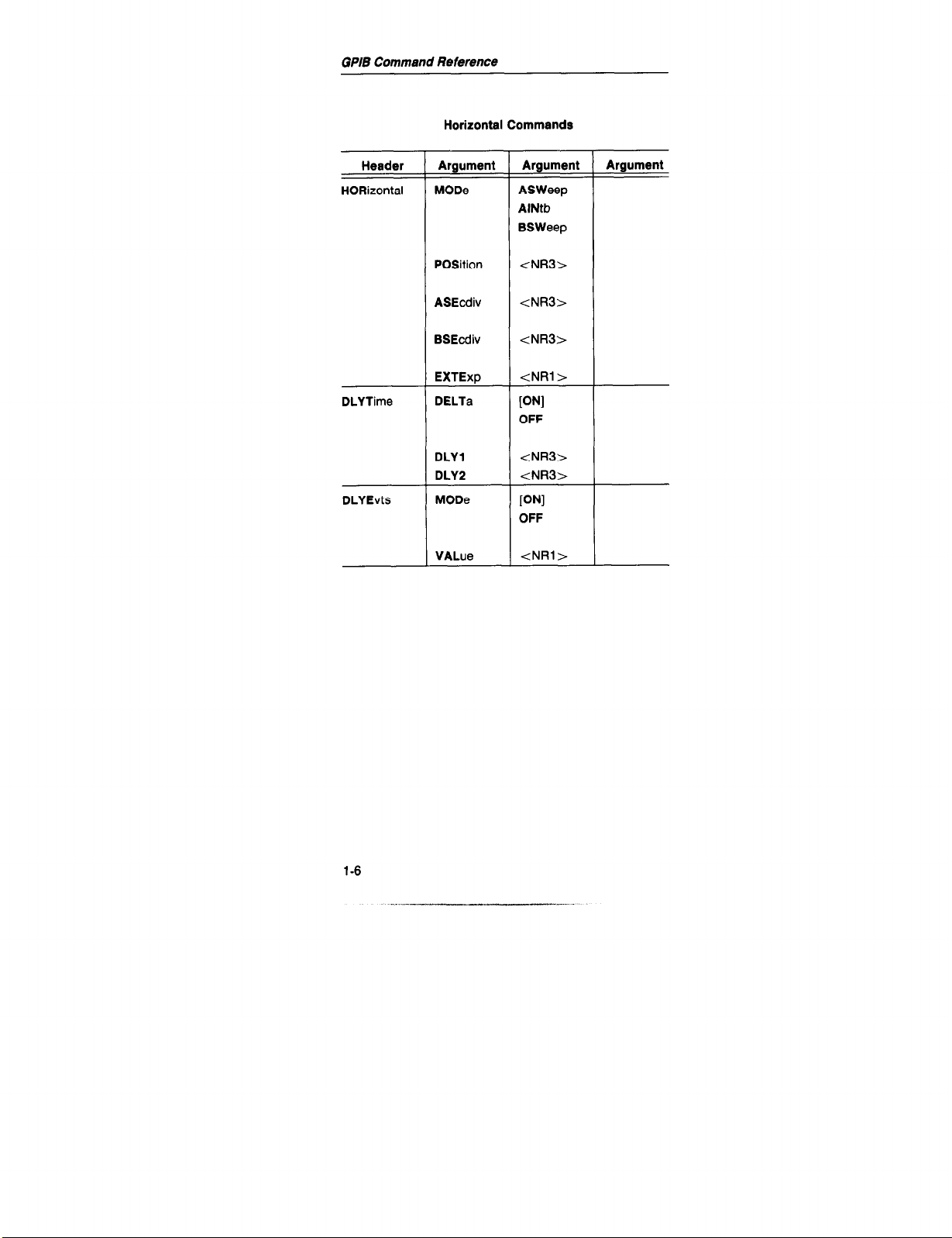
Horizontal Commands
Header
HORizontal
DLYTime
DLYEvts
Argument
MODe
POSition
ASEcdiv
BSEcdiv
EXTExp
DELTa
DLYl
DLY2
MODe
VALue
Argument
ASWeep
AlNtb
BSWeep
<NR3>
<NR3>
<NR3>
<NRl>
WI
OFF
<NR3>
<NR3>
WI
OFF
<NRi>
Argument
1-6
Page 12
GPIB Command Reference
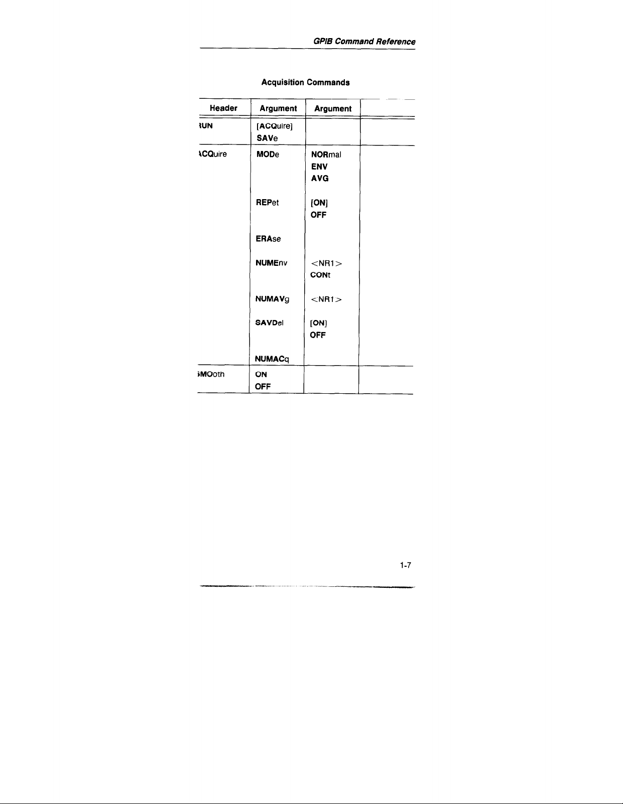
Acquisition Commands
Header
IUN
\CQuire
iMOoth
Argument
[ACQuireI
SAVe
REPet
ERAse
NUMEnv
NUMAVg
SAVDel
NUMACq
ON
OFF
Argument
NORmal
ENV
AVG
IONI
3FF
<NRl>
CONt
<NRl>
PJI
OFF
Page 13
GPIB Pocket Guide
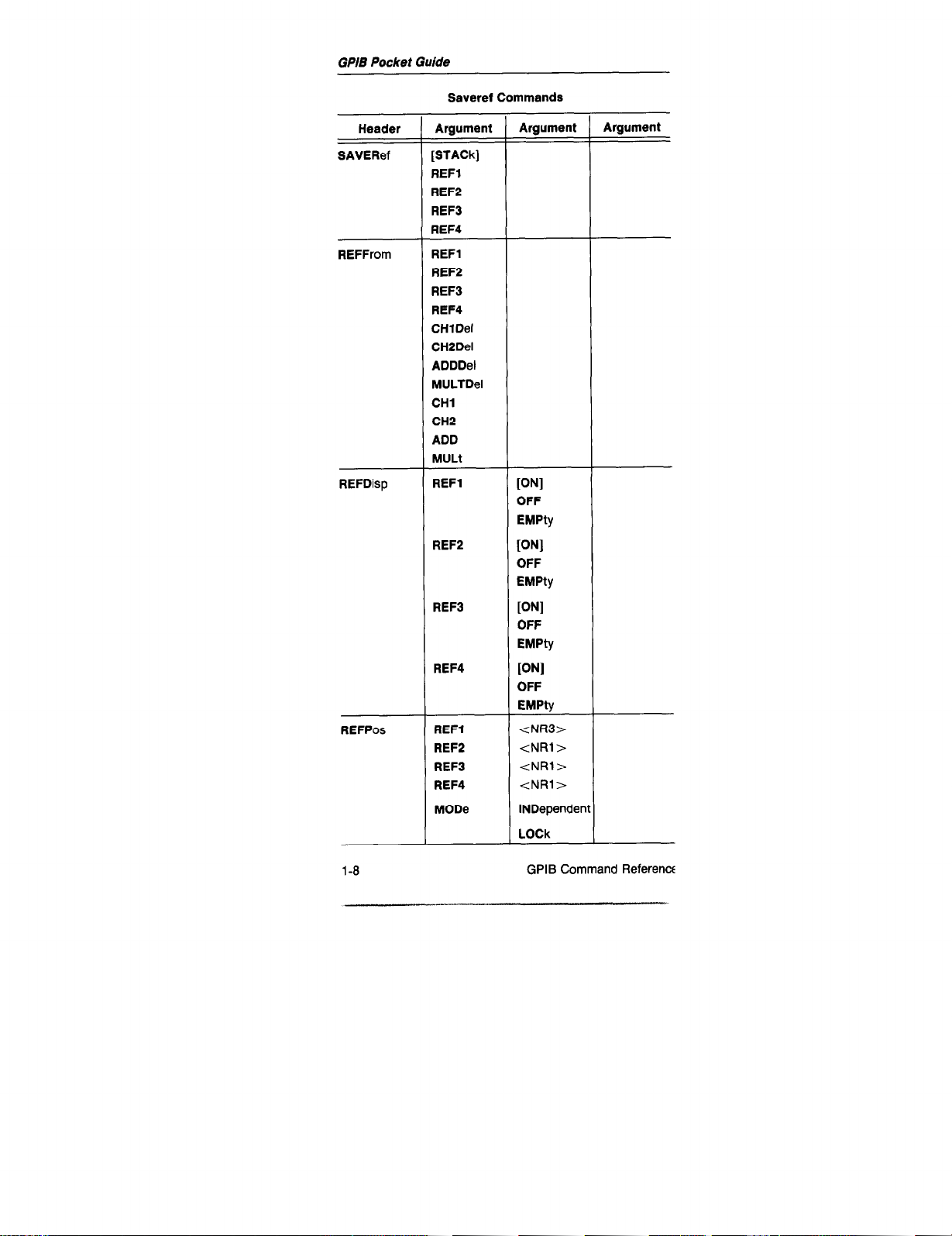
Saveref Commands
Header
SAVERef
REFFrom
REFDisp
REFPos
Argument
[STACk]
REFl
REF2
REFB
REF4
REFl
REF2
REF3
REF4
CHlDel
CH2Del
ADDDel
MULTDel
CHl
CH2
ADD
MULt
REFl
REF2
REF3
REF4
REFl
REF2
REF3
REF4
MODe
Argument
WI
OFF
EMPty
PJI
OFF
EMPty
[ONI
OFF
EMPty
[ONI
OFF
EMPty
<NR3>
tNRl>
tNRl>
tNRl>
LOCk
Argument
l-8
GPIB Command Reference
Page 14

Display Commands
GPIB Pocket Guide
Header
INTENSlty
REAdout
MENuoff
MESSage
Argument
DlSPlay <NR3>
REAdout tNR3>
GRAt <NR3>
INTENS
VECtors
Argument
<NR3>
WI
OFF
WI
OFF
<NRl>
CLRstate
“string”
L
Argument
GPIB Command Reference
_
l-9
-.-..~
Page 15
GPlB Command Reference
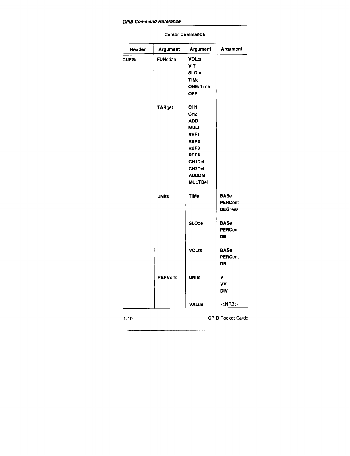
Cursor Commands
Header
CURSor
Argument
FUNction
TARget
UNlts
Argument
WOLts
V.T
SLOpe
Wle
ONE/Time
OFF
CHl
CH2
ADD
MULt
REFl
REFP
REF3
REF4
CHlDel
CH2Del
ADDDel
MULTDel
TlMe
Argument
BASe
PERCent
DEGrees
l-10
REFVolts
SLOpe
VOLts
UNlts
VALue
BASe
PERCent
DB
BASe
PERCent
DB
V
vv
DIV
<NR3>
GPIB Pocket Guide
Page 16

GPIB Command Reference
Cursor Commands (cant)
Header
:URSor
con0
Argument
FIEFSlope
REFTime
NE Wref
XPOS
YPOS
Argument
XUNit
YUNit
VALue
UNlts
VALue
ONE
TWO
ONE
TWO
Argument
SEC
CLKs
V
vv
DIV
V
vv
DIV
<NR3>
SEC
CLKs
tNR3>
<NR3>
<NR3>
<NR3>
<NR3>
rpos
MODe
DlSPlay
SELect
iPlB Pocket Guide
ONE
TWO
DELTa
ABSOlute
VALue
UNlts
ONE
TWO
<NR3>
<NR3>
1-11
Page 17

GPIB Command Reference
Automatic Feature Commands
Header
AUTOSetup
VALue?
UNlts?
MEASuremen
Argument
MODe
EXEcute
RESolution
<types9
<tVDeS>s
t
DlSPlay
MARk
WlNdow
METhod
TWO
Argument
VIEW
PERlod
RlSe
FALI
PULS@
HI
LO
K’NI
OFF
PJI
OFF
[ONI
OFF
CURSor
HlStogram
MlNMax
TYPe
SOUrce
DSOurce
TYPe
SOUrce
DSOurce
Argument
<types9
<data src>I
<data src>I
<types>a
<data src>I
<data src>I
‘DISTal, PROXimal, MESlal, MINImum, MAXimum. MID, TOP,
BASe. MEAN, PKZpk, OVErshoot, UNDershoot, WIDth, PERlod,
FREquency. DUTY, RISe. FALI, RMS. AREa, DELAY, DMEsial
bCH1, CH2, ADD, MULL REFl, REFZ, REF3, REF4, CHlDel,
CH2Del. ADDDel. MULTDel
l-12
Page 18

GPIB Command Reference
Automatic Feature Commands (cant)
Header
lEASuremen
cant)
Argument
t
THRee
FOUr
DlSTal
MESlal
PROXimal
DMEsial
Argument
TYPe
SOUrce
DSOurce
TYPe
SOUrce
DSOurce
UNlts
PLEvel
VLEvel
UNlts
PLEvel
VLEvel
UNlts
PLEvel
VLEvel
UNlts
PLEvel
VLEvel
Argument
<types>a
tdata src>b
<data src>b
ctypes>a
<data src>b
<data srcBb
PERCent
VOLts
<NR3>
tNR3>
PERCent
VOLts
<NR3>
tNR3>
PERCent
VoLts
<NA3>
<NR3>
PERCent
VOLts
<NR3>
<NR3>
‘CHl, CH2, ADD, MUU, REFl, REFP, REFI, REF4, CHlDel,
:H2Del, ADDDel, MULTDel
DISTal. PROXimal, MESlal. MINImum, MAXimum, MID. TOP,
3ASe. MEAN, PKPpk, OVErshoot, UNDershoot, WIDth. PERlod,
‘REquency, DUTY, RISe, FALI, RMS, AREa, DELAY, DMEsial
l-13
Page 19

Header
Sequencer Commands
T
-r
Argument
Argument Argument
SETUp
LLPrgm
PRGm?
SAVe
RECall
ACTion
FORCe
DELEte
MEMoty
NAMes
CLEar
“ascii string”
“ascii string”
ONE
TWO
THRee
FOUr
FlVe
“ascii string”
ONE
TWO
THRee
FOUr
FlVe
‘ascii string”
tNRl>
where:
1 = Repeat
2 = Selfcal
4 = Selftest
8 = Auto Setup:
16= Print/Plot
32=Bell
64=SRQ
126=Pause
256= Protect
[ONI
OFF
‘ascii string”
OFF
1
1-14
GPIB Pocket Guide
-
l_l.-...
Page 20

GPIW Commend Reference
Output Commands
Header
DEVlce
PRlnt
Argument
TYPe
SETTlngs
GRAt
TEXt
WAVfrm
PAGesize
Argument
THInkjet
HPGI
[ONI
OFF
WI
OFF
K’NI
OFF
WI
OFF
us
A4
GPIB Pocket Guide
1-15
Page 21

GPIB Command Reference
Miscellaneous Commands
Header
ID?
DEBug
HELD?
INIT
LONg
SET?
LLSet
PATh
BELI
REM
TIMe?
DT
Argument
WI
OFF
PANel
GPlb
SRQ
[BOTh]
[ONI
OFF
<binary
block>
[ONI
OFF
“ascii strina”
OFF
Argument Argument
1-16
RUN
SODRUN
STEp
‘ascii string”
GPIB Pocket Guide
Page 22

GPIB Command Reference
Waveform Commands
Header
Argument Argument
Argument
IAVfrm?
URVe
<wfm
data>
ATa
ENCdg
ASCii
RPBinary
RlBinary
RlPartial
RPPartial
TARget
REFl
REF2
REF3
REF4
SOUrce
DSOUrce
:Hl, CH2, ADD, MULt, REF1, REF2, REFB, REF4, CHlDel.
H2Del, ADDDel, MULTDel
<types9
<tVDeS>a
PIB Pocket Guide 1-17
Page 23

GPJB Command Reference
Waveform Commands (cant)
Header
WFMpre
FAStxmit
Argument
WFld
NR.Pt
PT.Fmt
XUNit
XlNcr
PT.Off
YUNit
Yrvlult
ENCdg
YOFf
BN.Fmt
<NRl>
DELTa
NORmal
OFF
ENCdg
Argument
‘ascii string”
Y
ENV
SEC
<NR3>
<NRl>
V
vv
DIV
<NR3>
ASCii
BlNary
<NR3>
RI
RP
CHl
CH2
BOTh
CHl
CH2
BOTh
RlBinaty
RPBinary
RlPartial
RPPartial
Argument
l-18
GPIB Pocket Guid
Page 24

IAXimum?
GPIB Command Reference
Waveform Data Commands
IAVg?
iYSteresis
MRection
I I I
<NRl>
PLUS
MINUS
3PlB Pocket Guide 1-19
Page 25

GPIB Command Reference
Service Request Commands
l-20 GPIB Pocket Guide
Page 26
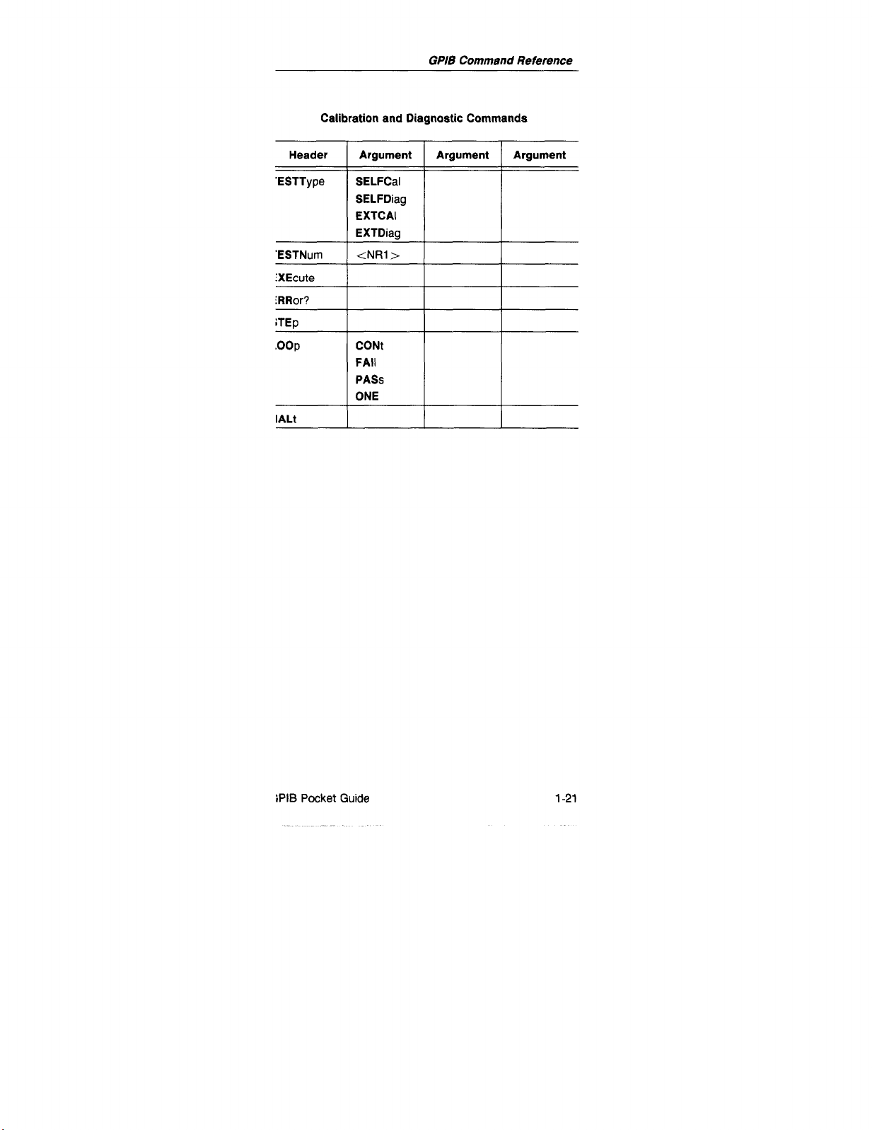
GPIS Command Reference
Calibration and Diagnostic Commands
iPIB Pocket Guide
l-21
Page 27

Alphabetical GPIB Command Reference
Alphabetical GPl5
Command Reference
Header Argument
rCQuire MODe
REPet
ERAse
NUMEnv
NUMAVg
SAVDel
NUMACq
Argument
NORmal
ENV
AVG
[ONI
OFF
<NRl>
CONt
<NRl>
WI
OFF
Argument
;PlB Pocket Guide
2-l
_- .--._. I_
Page 28

Alphabetical GPIB Command Reference (cant)
Header
ATRigger
Argument
MODe
SOUrce
LOGsrc WORd
Coupling
LEVel tNR3>
Argument
AUTOLevel
AUTO
NORmal
SGLseq
CHl
CH2
LlNe
VERtical
EXTl
EXT2
A.6
OFF
AC
DC
LFRej
HFRej
NOlserej
TV
Argument
2-2
SLOpe PLUS
MINUS
GPIB Pocket Guide
Page 29

Alphabetical G/JIB Command Reference
Alphabetical GPIB Command Reference (cant)
Header
ATRigger
;cont)
AUTOSetup
AVG?
BELI
Argument
POSition
HOLdoff
ABSElect
MINImum
MAXimum
STATe
CLRstate
MODe
EXEcute
RESolution
Argument
<NRl>
<NR3>
A
B
VIEW
PERlod
RlSe
FALI
PULse
HI
LO
Argument
GPIB Pocket Guide
2-3
Page 30

Alphabetical GPIB Command Reference
Alphabetical GPIB Command Reference (cant)
Header
BTRigger
Argument
UlODe
IXTCLk
SOUrce
Coupling
LEVel
SLOpe
Argument
1
IUNSaft
F
‘Rlgaft
1
u
ONI
C
)FF
(
:Hl
(
:H2
\
NORd
\
ilERtical
I
ZXTl
FXT2
I
1
AC
I
DC
I
LFRej
I
HFRej
I
NOlserej
<NR3>
PLUS
MINUS
Argument
BUSv?
BWLimit
CER
2-4
POSition <NRl>
TWEnty
HUNdred
FULI
[ONI
OFF
GPIB Pocket Guide
-.- . ..--.
Page 31

Alphabetical GPIB Command Reference
Alphabetical GPIB Command Reference (cant)
Header
Hl (or CH2)
‘URSor
Argument
VOLts
VARiable
POSition
Coupling
FlFty
INVert
FUNction
TARget
UNlts
Argument
<NR3>
<NR3>
<NR3>
AC
DC
GND
[ONI
OFF
WI
OFF
VOLts
V.T
SLOpe
TlMe
ONE/Time
OFF
CHl
CH2
ADD
MULt
REFl
REF2
REF3
REF4
CHl Del
CH2Del
ADDDel
MULTDel
TlMe
SLOpe
Argument
BASe
PERCent
DEGrees
BASe
PERCent
DB
iPlB Pocket Guide
2-5
-
Page 32
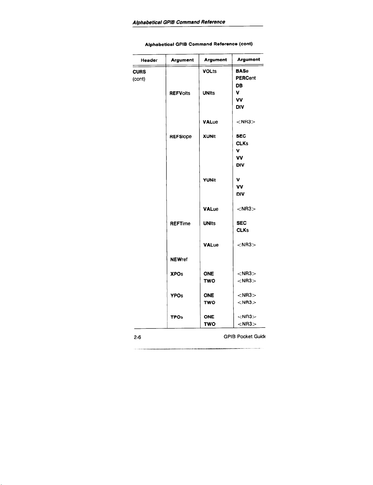
Alphabetical GPIB Command Reference
Alphabetical GPIB Command Reference (cant)
Header
CURS
(cant)
Argument
REFVolts
REFSlope
REFTime
Argument
VOLb
UNlts
VALue
XUNit
YUNit
VALue
UNlts
Argument
BASe
PERCent
DB
V
vv
DIV
<NR3>
SEC
CLKs
V
vv
DIV
V
vv
DIV
<NR3>
SEC
CLKs
2-6
NEWref
XPOS
YPOS
rpos
VALue
ONE
TWO
ONE
TWO
ONE
TWO
<NR3>
<NR3>
<NR3>
<NR3>
<NR3>
<NR3>
<NR3>
GPIB Pocket Guide
Page 33

Alph8betiGal GPIB Commend Reference
Alphabetical GPIS Command Reference (cant)
Header
ms
:ont)
:URVe
IATa
Argument
MODe
DlSPlay
SELect
twfm
data>
ENCdg
TARget
SOUrce
Argument
DELTa
ABSOlute
WALue
UNlts
ONE
TWO
ASCii
RPBinary
RlBinary
RlPartial
RPPartial
REFl
REF2
REF3
REF4
<data src>’
<data src>b
Argument
J
CHl, CH2, ADD, MULt, REFl, REFZ, REF3, REF4, CHlDel,
:H2Del, ADDDel, MlJLTDel
iPlB Pocket Guide
-___-... ---___
2-7
Page 34

Alphabetical GPIB Command Reference
Alphabetical GPIB Command Reference (cant)
Header
DEVlce
DIRection
DLYEvts
DLYTime
Argument
TYPe
SETTlngs
GRAt
TEXt
WAVfrm
PAGesize
PLUS
MINUS
MODe
VALue
DELTa
Argument
THinkjet
HPGI
WI
OFF
PNI
OFF
WI
OFF
[ONI
OFF
us
A4
WI
OFF
<NRl>
WI
OFF
Argument
DLYl <NR3>
DLYP <NR3>
2-8 GPIB Pocket Guide
_,_ _. .- ,.-
..- _
Page 35

Alphabetical OF/B Command Reference
Alphabetical GPIB Command Reference (cant)
STEp
“ascii string”
IRRor?
FVEnt?
IXEcute
ZXR
EXTGain EXTl
WI
OFF
NORmal
Argument
DlVl
DIV5
DlVl
DIV5
CHl
CH2
BOTh
CHl
CH2
BOTh
T
Argument
OFF
ENCdg
1
3PlB Pocket Guide
RlBinary
RPBinary
RlPartial
RPPartial
2-9
Page 36

Alphabetical GPIB Command Reference
Alphabetical GPIB Command Reference (cant)
Header
FORMat
HALt
HELP?
HORizontal
Hysteresis
ID?
INIT
Argument
Argument
PI
OFF
MODe
POSition
ASEcdiv <NR3>
BSEcdiv <NR3>
EXTExp
<NRl>
PANel
ASWeep
AlNtb
BSWeep
<NR3>
<NRl>
Argument
INITAt50
2-10
SRQ
[BOTh]
GPIB Pocket Guide
Page 37

Alphabetical GPIB Command Reference
Alphabetical GPIB Command Reference (cant)
Header
ITRigger
Argument
MODe
EXTCLk
SOUrce
Coupling
LEVel
SLOpe
Argument
RUNSaft
TRIgaft
WI
OFF
CHl
CH2
WORd
VERtical
EXTl
EXT2
AC
DC
LFRej
HFRej
NOlserej
<NR3>
PLUS
MINUS
Argument
POSition
UR
UTENSlty
iPIE Pocket Guide
PNI
OFF
DlSPlay
REAdout
GRAt
INTENS
VECtors
<NRl>
<NR3>
<NR3>
<NA3>
<NR3>
PI
OFF
I
2-11
Page 38

Alphabetical GPIB Command Reference
Alphabetical GPIB Command Reference (cant)
Header
LEVel
LLPrgm
LLSet
LOCk
LONg
LOOP
MANtrig
MAXimum?
MEASuremer
Argument
<NRl>
“ascii string’
<binary
block>
ON
OFF
LLO
WI
OFF
CONt
FAII
PASS
ONE
It
DlSPlay
MARk
Argument
WI
OFF
PI
OFF
Argument
WlNdow
METhod
2-12 GPIB Pocket Guide
[ONI
OFF
CURSor
HlStogram
MlNMax
Page 39

Alphabetical GPIB Command Reference
Alphabetical GPIB Command Reference (cant)
Header
MEASuremer
(COW)
Argument
ONE
Argument
TYPe
SOUrce
DSOurce
TWO TYPe
SOUrce
DSOurce
THRee TYPe
SOUrca
DSOurce
FOUr
rYPe
SOUrce
DSOurce
DlSTal
UNlts
JLEvel
VLEvel
MESlal UNlts
PLEvel
VLEvel
Argument
<types9
<data src>b
<data src>b
<types9
<data src9
<data src9
ctypes>a
<data src9
<data src9
<type59
<data srwb
<data src>b
PERCent
VOLts
<NR3>
<NR3>
PERCent
VOLts
tNR3>
tNR3>
PROXimal
UNlts
PERCent
VOLts
PLEvel
-
‘DISTal, PROXimal, MESlal, MINImum, MAXimum, MID, TOP,
%ASe, MEAN. PKZpk, OVErshoot, UNDershoot, WIDth, PERlocI,
:REquency, DUTY, RISe, FALL RMS, AREa, DELAY, DMEsial
‘CHl, CH2, ADD, MULt, REFl, REF?, REFB, REF4, CHlDel,
:H2Del, ADDDel, MULTDel
VLEvel
<NR3>
<NR3>
iPlB Pocket Guide 2-13
Page 40

Alphabetical GPIB Command Reference
Alphabetical GPIB Command Reference (cant)
Header Argument Argument Argument
MEASurement DMEsial UNlts PERCent
MESSage tNRl> ) “string” 1
CLRstate
MINimum?
NCRoss?
OPC
PATh
PCRoss?
PID
PRGm?
PRlint
PROSe?
REAdout
[ONI
OFF
[ONI
OFF
WI
OFF
“ascii string” OFF
CHl
CH2
EXTl
EXT2
WI
( OFF
2-14 GPIB Pocket Guide
Page 41

AQhabetical GPB Command Reference
Alphabetical GPIB Command Reference (cant)
Header
:EFDisp
!EFFrom
:EFPos
Argument
REFi
REF2
REF3
REF4
REFi
REF2
REF3
REF4
CHl Del
CH2Del
ADDDel
MULTDel
CHl
CH2
ADD
MULt
REFl <NR3>
REFP <NW >
REF3 <NRl>
REF4
MODe
WI
OFF
EMPty
WI
OFF
EMPty
WI
OFF
EMPty
WI
OFF
EMPtv
<NFil>
INDependeni
LOCk
Argument
iPIB Pocket Guide 2-15
Page 42
Alphabetical GPIB Command Reference
Alphabetical GPIB Command Reference (cant)
Header
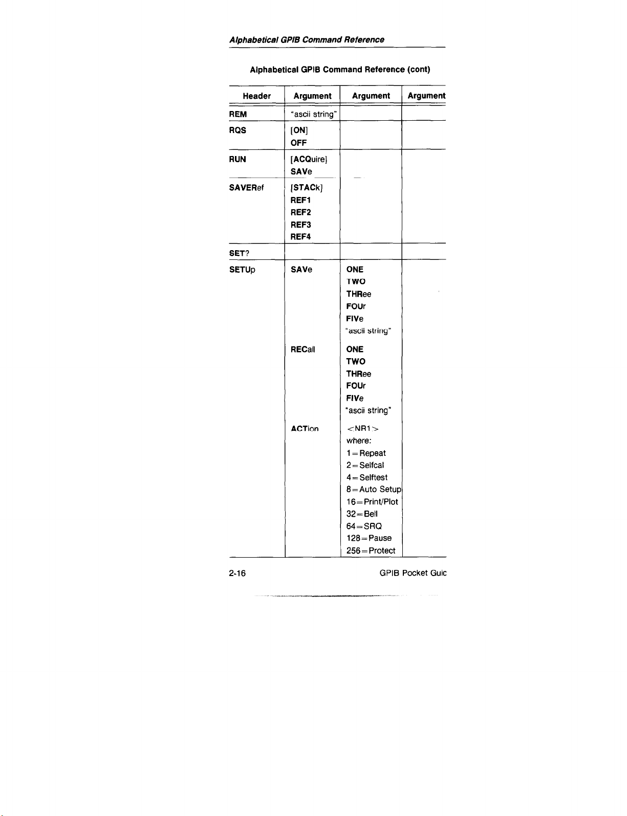
REM
RQS
RUN
SAVERef
SET?
SETUp
Argument
“ascii string”
VI
OFF
[ACQuireI
SAVe
[STACk]
REFl
REF2
REF3
REF4
SAVe
RECall
Argument
ONE
TWO
THRee
FOUr
FlVe
“ascii string”
ONE
TWO
THRee
FOUr
FlVe
‘ascii string”
Argument
2-16
ACTion
<NRl>
where:
1 = Repeat
2 = Selfcal
4= Selftest
8 = Auto Setup
16= Print/Plot
32=Bell
64=SRQ
128= Pause
256= Protect
GPIB Pocket Guic
Page 43

Atphabeticar GPIB Commend Reference
Alphabeticet GPIB Command Reference (cant)
Header
iETUp
cant)
ZETTV
Argument
FORCe
DELEte
MEMory
NAMes
CLEar
ICOupling
INTERlaced
TVClamp
TVLine
Argument
PNI
OFF
‘ascii string”
FLDl
‘LD2
ALT
TVLine
FLDl
TVLine
WI
OFF
<NRi>
Argument
LCNTReset
LCNTStart
SYNC
SPIB Pocket Guide 2-17
FlOnly
BOTh
PREfld
ATFld
PLUS
MINUS
.-.. _ ~- .._ ..- ..-.__ _I
Page 44

Alphabetical GPO3 Command Reference
Alphabetical GPIB Command Reference (cant)
Header
SETWord
SMOoth
SNAp
STARt
STEp
STOp
TESTNum
TESTType
TIMe?
Argument
Argument
i=
RADix
CLOck ASYnc
WORd
PROBe
ON
OFF
<NRl>
<NRl>
tNRl>
SELFCal
SELFDiag
EXTCAI
EXTDiag
OCT
HEX
FALI
RlSe
tascii
binary
data>
Argument
2-18 GPIB Pocket Guidl
Page 45

AIphabeficel
GPls
Commend
Reference
Alphabetical GPIB Command Reference (cant)
IMAximum? 1
i C”, ::Mldum?
CH2
ADD
MULt
DlSPlay
Argument
WI
OFF
P’JI
OFF
WI
OFF
WI
OFF
XY
YT
Argument
DISTal, PROXimal,
ASe, MEAN, PKlpk, OVErshoot, UNDershoot. WIDth. PERlod,
REquency. DUTY, RI% FALI, RMS, AREa, DELAY, DMEsial
IPIB Pocket Guide 2-19
MESlal, MINImum, MAXimum. MID,
TOP,
Page 46
Alphabetical GPIB Command Reference
Alphabetical GPIB Command Reference (cant)
Header Argument
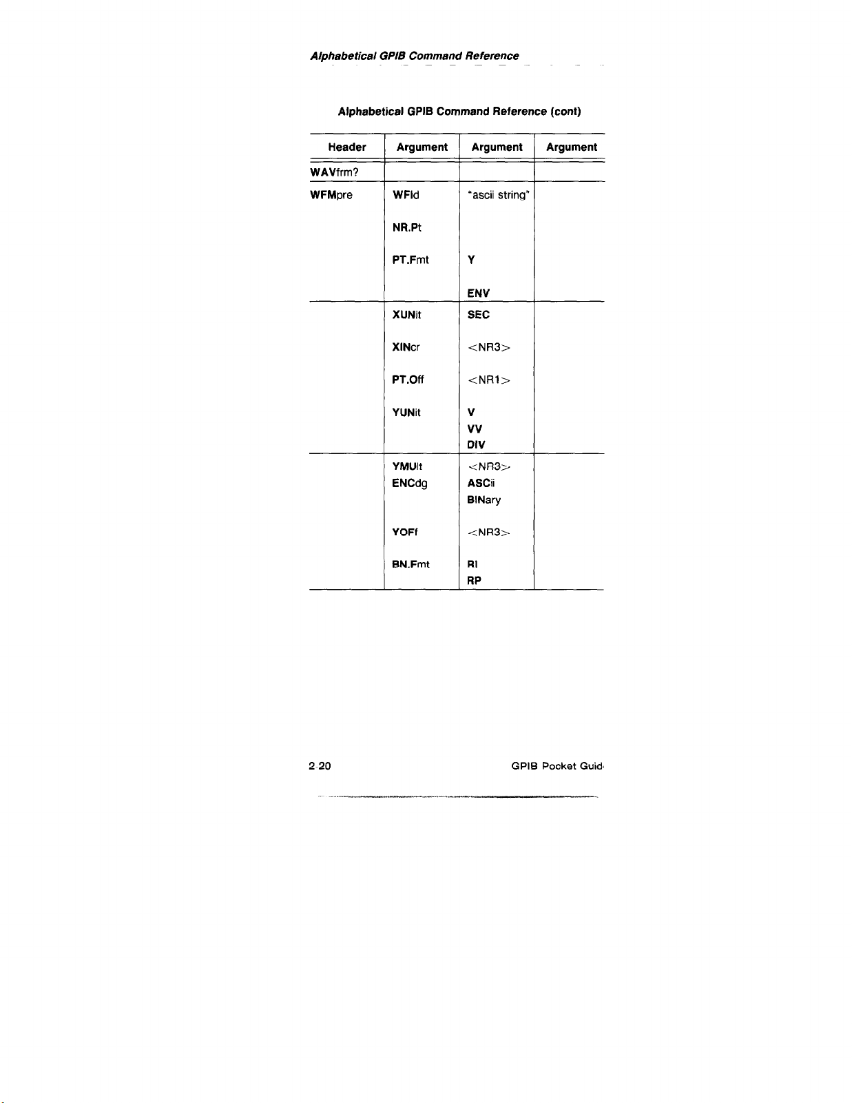
WAVfrm?
WFMpre WFld
NR.Pt
PT.Fmt
XUNit
XlNcr
PT.Off
YUNit
YMUlt
ENCdg
YOFf
Argument
“ascii string”
Y
ENV
SEC
<NR3>
<NRl>
V
vv
DIV
<NR3>
ASCii
BlNary
<NR3>
Argument
BN.Fmt
2-20 GPIB Pocket Guidl
Page 47
Event Tables
Event Tables
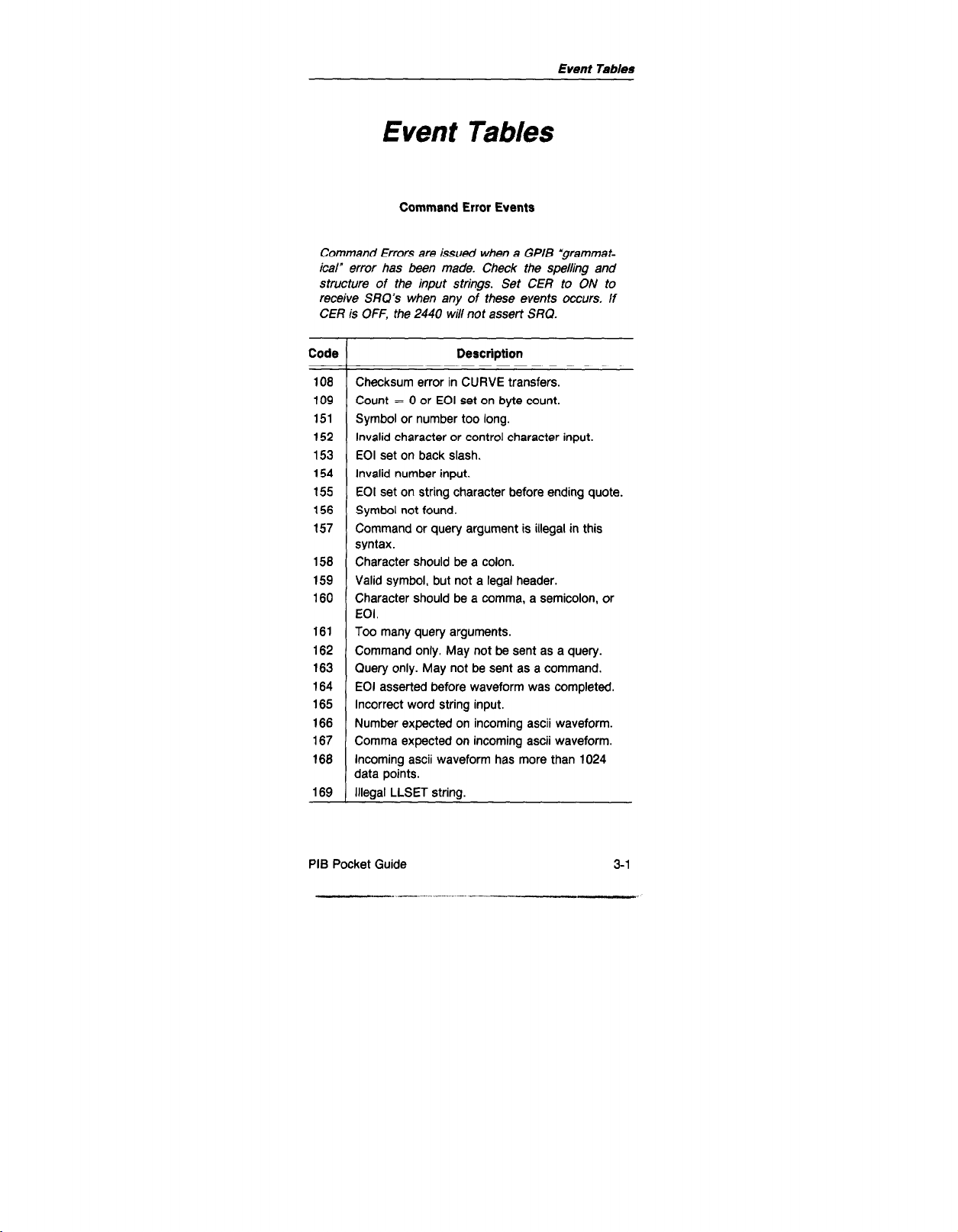
Command Error Events
Command Errors are issued when a GPIB *grammatical” error has been made. Check the spelling and
structure of the input strings. Set CER to ON to
receive SRQ’s when any of these events occurs. If
CER is OFF, the 2440 will not assert SRQ.
Code
108
109
151
152
153
154
155
156
157
158
159
160
161
162
163
164
165
166
167
168
169
Description
Checksum error in CURVE transfers.
Count = 0 or EOI set on byte count.
Symbol or number too long.
Invalid character or control character input.
EOI set on back slash.
Invalid number input.
EOI set on string character before ending quote.
Symbol not found.
Command or query argument is illegal in this
syntax.
Character should be a colon.
Valid symbol, but not a legal header.
Character should be a comma, a semicolon, or
EOI.
Too many query arguments.
Command only. May not be sent as a query.
Query only. May not be sent as a command.
EOI asserted before waveform was completed.
Incorrect word string input.
Number expected on incoming ascii waveform.
Comma expected on incoming ascii waveform.
Incoming ascii waveform has more than 1024
data points.
Illegal LLSET string.
PIB Pocket Guide 3-l
___. ..^_
-. ---
Page 48

Event Tables
Execution Error Events
Execution errors are issued when a particular scope
setting doesn’t allow the current command to be exe-
cuted the way the user would like. Set EXR to ON
to receive SRQ’s when any of these events
occurs.
EXR is OFF, the 2440 will not assert SRQ.
If
Code
203
250
251
252
253
254
255
256
257
259
260
261
262
263
264
265
266
267
268
269
Description
I/O buffers full, output dumped.
Selected recall memory is unset.
Measurement requested on an empty reference
memory.
Waveform requested via GPIB is not valid or
available.
Too many numbers were sent in (stack overflow’
No Video Option installed when SETTV
commands issued.
Target selected for cursors not displayed.
Clear overload condition before changing to 50 S
coupling.
Waveform selected for reference source is not
valid.
No ADD or MULT on previously SAVEd
waveforms; ENVELOPE waveform invalid.
No cal commands allowed while front panel is
doing cal.
No sequence by that name to delete.
Can’t save sequence-out of memory.
Can’t send a partial waveform to an empty ref.
Not enough edges to extract the parameter.
Asked for rise time but no rising edge.
Asked for fall time but no falling edge.
Delay Measurement targets must have matching
Sec/Div settings.
One or more of the following conditions are not
satisfied:
BASE<PROXIMAL<MESIAL=zDlSTALsTOP,
BASE<MESIALP<TOP,
PROXIMAL>MIN and DISTALtMAX,
MIN<MESIAL2<MAX
Repet waveform not filled when measurement
requested.
3-2 GPIB Pocket Guic
Page 49

Execution Error Events (cant)
Event Tables
Code
270 No measurements during live Roll-enter Save
mode first.
271 Measurement requested on a Delta Delay target
but B Horizontal and Delta Delay modes are not
on.
272 RMS measurement invalid due to 2440 internal
overflow.
275 Sequencer currently active-new sequence
commands not accepted.
Internal Errors are issued when something has hap-
pened to the hardware of the 2440 that the controller
might like to know about. Set INR to ON to receive
SRQ’s when any of these events occurs. tf INR is
OFF, the 2440 will not assert SRQ.
Cal execute command returns with FAIL.
A 50-R overload occurred. Input coupling
Description
Internal Errors
System Messages
System Messages are issued to inform the controller
of bus system management events. There is no way
to mask these events except by setting RQS to OFF.
The event 459 indicates that the 2440 is currently
asserting SRQ on the bus and the controller must
read the status byte out before reading the
event code.
Code Description
401 2440 was just powered on.
There is an SRQ pending.
459
iPlB Pocket Guide 3-3
Page 50

Event Tables
User Request Events
User Request events are issued when any of the
bezel buttons on the 2440 front panel are pushed.
The MENUOFF command needs to be issued before
these events will be reported. This command allows
the user to monitor front panel responses (as well as
to clear the menu for writing custom text to the
screen when desired). Set USER to ON to receive
SRQ’s when any of these events occurs. If USER is
OFF, the 2440 will not assert SRQ.
Code Description
450 Menu key #l was pushed (leftmost)
451 Menu key #2 was pushed.
452 Menu key #3 was pushed.
453 Menu key #4 was pushed.
454 Menu key #5 was pushed (rightmost).
Probe Identify Events
Probe ldentifv events are reported by the 2440 when
the probe identify feature found on certain probes is
actuated. (You can replicate this action by grounding
the outer code ring to the inner shell on the front
panel input BNC.) Set PID to ON to receive SRQ’S
when any of these events occurs. If P/D is OFF, the
2440 will not assert SRQ.
Code
455 CHl probe identify was used.
456 CH2 probe identify was used.
457 EXTl probe identify was used.
458 EXT2 probe identify was used.
3-4 GPIB Pocket Guide
Description
Page 51

Event Tables
Operation Complete Events
Operation Complete events are issued when the con-
troller needs to know when the 2440 has completed
a task. Set OPC to ON to receive SRQ’s when any
of these events occurs. If OPC is OFF, the 2440 will
not assert SRQ.
Code
461
Single Sequence has completed.
462
Save-On-Delta has detected a difference and
gone to Save.
463
A print or plot is complete.
464
Current cal command started with an EXECUTE
is done.
465 Step command is done.
Complete sequence is done.
466
467 Autoset search is complete.
Execution Warnings are issued when the command
received has been done, but the result might not be
what the user expected to see. Set EXW to ON to
receive SRQ’s when any of these events occurs, If
EXW is OFF, the 2440 will not assert SRQ.
Code Description
539 50 MHz bandwidth limit not available in 2440.
Bandwidth limit set to 100 MHz.
540 RMS measurements need at least 1 period.
541 Amplitude too small to do an accurate timing
measurement.
542 Measurement crossing points on Envelope may
be misplaced.Turn on Marks to see where
measurement was taken.
543 Too few points acquired to guarantee Histogram
accuracv for this measurement.
Description
Execution Warning
GPIB Pocket Guide 3-5
Page 52
Event Tables
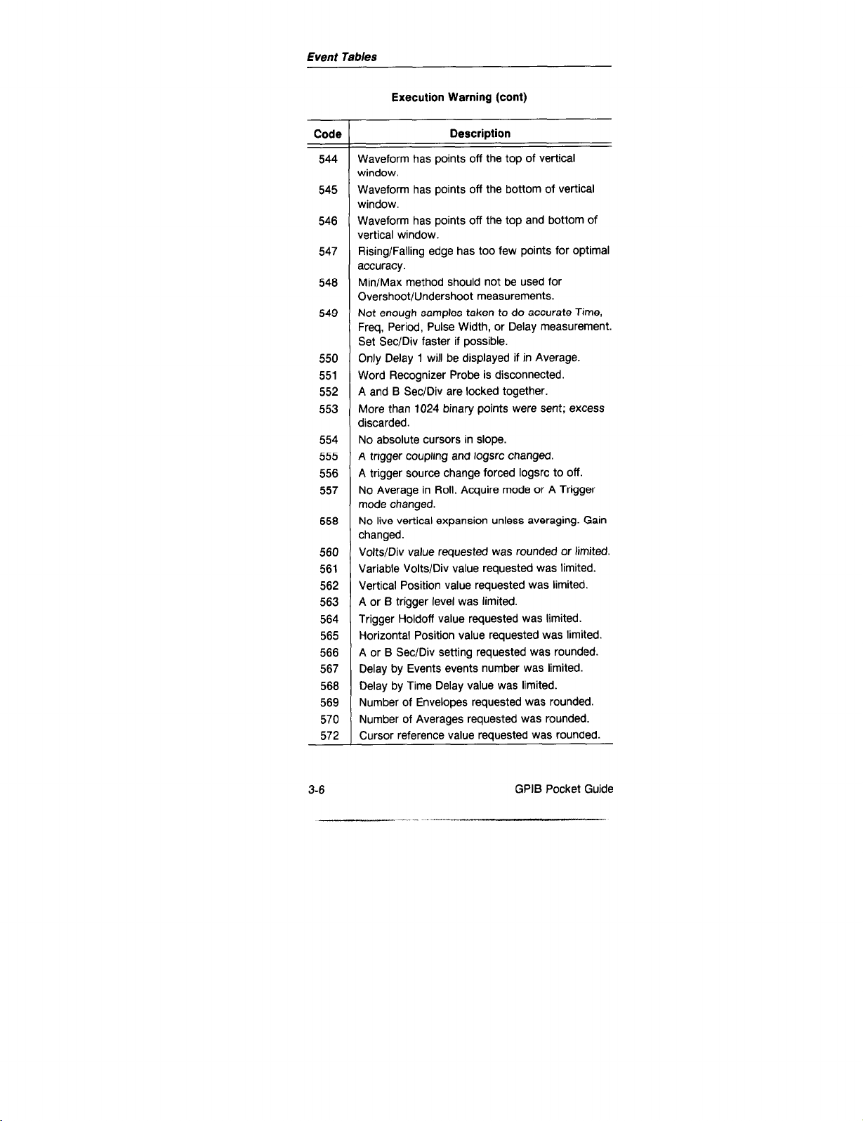
Execution Warning (cant)
Code
Waveform has points off the top of vertical
544
window.
Waveform has points off the bottom of vertical
545
window.
Waveform has points off the top and bottom of
546
vertical window.
Rising/Falling edge has too few points for optimal
547
accuracy.
Min/Max method should not be used for
548
Overshoot/Undershoot measurements.
549
Not enough samples taken to do accurate Time,
Freq, Period, Pulse Width, or Delay measurement.
Set Sec/Div faster if possible.
Only Delay 1 will be displayed if in Average.
550
Word Recognizer Probe is disconnected.
551
552
A and B Sec/Div are locked together.
More than 1024 binary points were sent; excess
553
discarded.
554
No absolute cursors in slope.
555
A trigger coupling and logsrc changed.
A trigger source change forced logsrc to off.
556
No Average in Roll. Acquire mode or A Trigger
557
mode changed.
No live vertical expansion unless averaging. Gain
558
changed.
560 Volts/Div value requested was rounded or limited.
561 Variable Volts/Div value requested was limited.
Vertical Position value requested was limited.
562
A or B trigger level was limited.
563
Trigger Holdoff value requested was limited.
564
Horizontal Position value requested was limited.
565
A or B Sec/Div setting requested was rounded.
566
Delay by Events events number was limited.
567
568 Delay by Time Delay value was limited.
Number of Envelopes requested was rounded.
569
Number of Averages requested was rounded.
570
572 Cursor reference value requested was rounded.
Description
3-6
GPIB Pocket Guide
Page 53

Command Error Events
Event Tables
Code
Horizontal position value (XPOS) for cursors was
573
limited.
Vertical position value (YPOS) for cursors was
574
limited.
Intensity value requested was limited.
575
Line number of screen text message was limited.
576
578
The XINCR value was rounded or limited.
579
The PTOFF value was rounded or limited.
580
The YMULT value was rounded or limited.
Trigger position number requested was limited.
582
An ascii data point was rounded to fit into 127 to
583
-128.
Waveform data level value requested
584
Start or Stop number was changed.
585
588 The YOFF value was limited.
587 Extexp value requested was limited.
Hysteresis number requested was rounded.
588
Attribute number requested was rounded.
589
Description
was
Device Dependent Message
Device Dependent messages are issued when the
front panel user of the 2440 has done something that
the controller
might
want to know
about.
DEVDEP to ON to receive SRQ’s when any of these
events occurs. If DEVDEP is OFF, the 2440 will not
assert SRQ.
limited.
Set
Code Description
650 Waveform was requested from front panel.
Waveform transmission was aborted from front
MENUOFF command was executed or front panel
I” 1 Lz pushed.
iPlB Pocket Guide 3-7
Page 54

Event Tables
Fatal Error
A Fatal Error is issued when something completely
unexpected happens inside the 2440. This normally
is caused by a hardware failure.
prevent this error from being reported except by
turning RQS to OFF.
Code Description
750 Fatal error.
There is no way to
3-8
GPIB Pocket Guid
_..-...- . ._.._ -, .---_- “”
Page 55

Event Tables
2440
On the following two pages is the 2440 Status Byte
able. It lists each status byte code, along with the
istrument status indicated by each code, that can be
eturned when the EVEnts query is sent by the controller.
Status bytes
iPlB Pocket Guide 3-9
Page 56

2440 Status Bytes
Title
Binarya
RQS Off
Idle
No Status To Report 000x 0000 0
Power On 010x 0001
Operation Complete
OROX
0010 2
User Request OROX 0011 3
Command Error OR1 x 0001 33
Execution Error ORlX 0010 34
internal Error OR1 x 0011 35
Execution Warning
ORlX 0101 37
Decimal
RQS On
Priority
3QS
Off
I
L
xx3
On
Idle
16
1
17
18
19
49
50
51
53
65
66
67
97
98
99
101
0
16
81
82
83
113
114
115
117
Page 57

Transmit Request 1 ROX 0011 131 147
195 211 2 8
Transmit Aborted 1 ROX 0100 132 148 196 212 2 8
Menuoff Pushed 1 ROX 0101 133 149 197 213 2 8
Fatal Error 1 Rl X 0011 --- --- 227 243 -- 10
Device Dependent Bit
RQS Bit
Error Bit
Busy Bit
a“R” is set to 1 if the GPIB and RQS are on; otherwise; it is 0.
“X” is the Busy Bit and will be set if the 2440 is busy at the time the status byte is read. Any
time the 2440 is doing something for which the OPC SRQ can be sent (calibration or self test,
single sequence, Save-On-Delta, or plotting) the bit will be sent true (1); otherwise, it
will be a 0.
Page 58

Character Charts
ASCII and 2440 Character Charts
3B Pocket Guide
4-1
Page 59
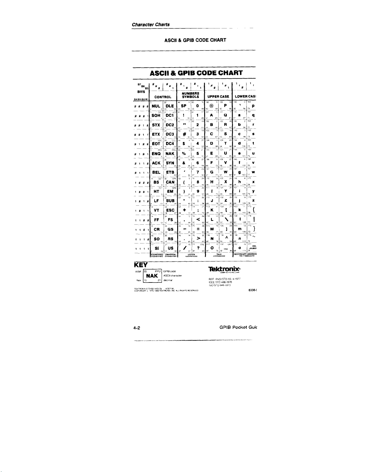
ASCII & GPIB CODE CHART
ASCII 81 GPIB CODE CHART
4-2
GPIB Pocket Guic
 Loading...