

Page 1

Series 2400 SourceMeter®
Quick Start Guide
2400S-903-01 Rev. E / September 2011
moc.yelhtiek.www
ECNEDIFNOC FO ERUSAEM RETAERG A
Page 2

Series 2400 SourceMeter
Quick S tart Guide
®
©2011, Keithley Instruments, Inc.
Document Number:
All rights reserved.
Cleveland, Ohio, U.S.A.
2400S-903-01 Rev. E / September 2011
Page 3

Page 4

The following safety precautions should be observed before using this product an d any associated instrumentation. Although some
instruments and accessories would normally be used with non-hazardous voltages, there are situations where hazardous conditions may
be present.
n
This product is intended for use by qualified personnel who recog
to avoid possible injury. Read and follow all installation, operation, and maintenance information carefully before using the product. Refer
to the user documentation for complete product specifications.
ize shock hazards and are familiar with the safety precautions required
Safety Precautions
If the product is used in a manner not sp
The types of product users are:
Responsible body is the
operated within its specifications and operating limits, and for ensuring that operators are adequately trained.
Operators use
They must be protected from electric shock and contact with hazardous live circuits.
Maintenance personnel perform routin
replacing consumable materials. Maintenance procedures are described in the user documentation. The procedures explicitly state if the
operator may perform them. Otherwise, they should be performed only by service personnel.
Service personnel are trained to
personnel may perform installation and service procedures.
Keithley Instruments products are designed for use with electrical signals that
Category II, as described in the International Electrotechnical Commission (IEC) Standard IEC 60664. Most measurement, control, and
data I/O signals are Measurement Category I and must not be directly connected to mains voltage or to voltage sources with high transient
over-voltages. Measurement Category II connections require protection for high transient over-voltages often associated with local AC
mains connections. Assume all measurement, control, and data I/O connections are for connection to Category I sources unless otherwise
marked or described in the user documentation.
Exercise extreme caution when a shock hazard is prese
American National Standards Institute (ANSI) states that a shock hazard exists when voltage levels greater than 30V RMS, 42.4V peak,
or 60VDC are present. A good safety practice is to expect that hazardous voltage is present in any unknown circuit before measuring.
the
individual or group responsible for the use and maintenance of equipment, for ensuring that the equipment is
product for its intended function. They must be trained in electrical safety procedures and proper use of the instrument.
ecified, the protection provided by the product warranty may be impaired.
e procedures on the product to keep it operating properly, for example, setting the line voltage or
work on live circuits, perform safe installations, and repair products. Only properly trained service
are rated Measurement Category I and Measurement
n
t. Lethal voltage may be present on cable connector jacks or test fixtures. The
c
Operators of this product must be protected from ele
prevented access and/or insulated from every connection point. In some cases, connections must be exposed to potential human contact.
Product operators in these circumstances must be trained to protect themselves from the risk of electric shock. If the circuit is capable of
operating at or above 1000V, no conductive part of the circuit may be exposed.
Do not connect switching cards directly to unlimited power circuits
connect switching cards directly to AC mains. When connecting sources to switching cards, install protective devices to limit fault current
and voltage to the card.
Before operating an instrument, ensure that the line cord is con
cables, test leads, and jumpers for possible wear, cracks, or breaks before each use.
tric shock at all times. The responsible body must ensure that operators are
. They are intended to be used with impedance-limited sources. NEVER
nected
to a properly-grounded power receptacle. Inspect the connecting
04/09
Page 5

When installing equipment where access to the main power cord is restricted, such as rack mounting, a separate main input power
!
disconnect device must be provided in close proximity to the equipment and within easy reach of the operator.
For maximum safety, do not touch the product, test cables, or any other instruments
AL W AYS remove power from the entire test system and discharge any capacitors before: connecting or disconnecting cables or jumpers,
installing or removing switching cards, or making internal changes, such as installing or removing jumpers.
Do not touch any object that could provide a current path to the common
make measurements with dry hands while standing on a dry, insulated surface capable of withstanding the voltage being measured.
The instrument and accessories must be used in a
equipment may be impaired.
Do not exceed the maximum signal levels of the instrument
and as shown on the instrument or test fixture panels, or switching card.
When fuses are used in a product, replace with the same type and rati
Chassis connections must only be used as shield connections for measuring
If you are using a test fixture, keep the lid closed while power is applied to the device under test. Safe operation requires the u
interlock.
If a screw is present, connect it to safety earth ground u
The symbol on an instrument means caution, risk of danger. The user should refer to the operating instructions located in the user
documentation in all cases where the symbo
The symbol on an instrument means caution, risk of danger. Use standard safety precautions to avoid personal contact with these
voltages.
ccordance with its specifications and operating instruct ions, or the safety of the
s and accessories, as defined in the specifications and operating information,
sing the wire recommended in the user documentation.
l is marked on the instrument.
side of the circuit under test or power line (earth) ground. Always
ng for continued protection against fire hazard.
circuits, NOT as safety earth ground connections.
while power is applied to the circuit under test.
se of a lid
The symbol on an instrument shows that the
The symbol indicates a connection terminal to the equipment frame.
If this symbol is on a product, it indicates that mercury is present in
disposed of according to federal, st
The WARNING he
associated information very carefully before performing the indicated procedure.
The CAUTION head
warranty.
Instrumentation and accessories shall not be connected to humans.
Before performing any maintenance, disconnect the line cord and all test cables.
T o maintain protection from electric shock and fire, replacement compon
and input jacks - must be purchased from Keithley Instruments. Standard fuses with applicable national safety approvals may be used if
the rating and type are the same. Other components that are not safety-related may be purchased from other suppliers as long as they
are equivalent to the original component (note that selected parts should be purchased only through Keithley Instruments to maintain
accuracy and functionality of the product). If you are unsure about the applicability of a replacement component, call a Keithley Instruments
office for information.
To clean an instrument, use a damp cloth or mild, water-based clea
directly to the instrument or allow liquids to enter or spill on the instrument. Products that consist of a circuit board with no case or chassis
(e.g., a data acquisition board for installation into a computer) should never require cleaning if handled according to instructions. If the
board becomes contaminated and operation is affected, the board should be returned to the factory for proper cleaning/servicing.
ading in the user documentation explains dangers that might result in personal injury or death. Always read the
ing in the user documentation explains hazards that could damage the instrument. Such damage may invalidate the
ate, and local laws.
surface may be hot. Avoid personal contact to prevent burns.
the display lamp. Please note that the lamp must be properly
ents in mains circuits - including the power transformer, test leads,
ner
. Clean the exterior of the instrument only. Do not apply cleaner
Page 6

Table of Contents
Section T opic Page
Introduction................................................................................................. 1-2
Source-measure ca
Front and rear panels......
Navigating menus and entering numeric data.....
Menu navigation.....
Numeric data entry (EDIT keys).......
Editing source and compliance values......
Editing keys......
Editing procedure......
Toggling the source and measure display fields .................................. 1-5
Basic connections......
Front/rear terminals se
2-wire connections ....
4-wire connections ............................................................................... 1-7
Cable guard......
Ohms guard .....
Remote command programming........................................................ 1-10
Basic SourceMeter operations......
Source-measure.....
Measure only (V or I)....
Measure ohms ................................................................................... 1-12
Remote command programming......
Settings to optimize performance....
Range................................................................................................. 1-
Speed................................................................................................. 1-18
Digits.................................................................................................. 1-
Filter................................................................................................... 1-
Rel (nulling offsets)....
Remote command programming......
Features to enhance DUT testing.......
Data store.....
Sweep operation....
Performing sweeps....
Limit testing......
Math functions.....
Pulse mode (Model 2430 only) .....
pabilities ...................................................................... 1-2
........................................................................... 1-3
....................................... 1-4
.............................................................................. 1-4
.................................................... 1-4
................................................. 1-4
.................................................................................... 1-4
........................................................................... 1-5
................................................................................. 1-6
lection............................................................... 1-6
........................................................................... 1-6
.................................................................................... 1-8
.................................................................................... 1-9
............................................................ 1-10
............................................................................ 1-10
...................................................................... 1-11
.................................................. 1-14
......................................................... 1-17
17
18
18
......................................................................... 1-19
.................................................. 1-20
..................................................... 1-20
...................................................................................... 1-20
............................................................................ 1-22
......................................................................... 1-26
.................................................................................. 1-30
............................................................................... 1-33
..................................................... 1-36
Page 7

Table of Contents Series 2400 SourceMeter® Quick Start Guide
2 2400S-903-01 Rev. E / September 2011
Page 8

Quick start topics
Topic Page
Introduction ....................................................................................1-1
Source-measure capabilities..........................................................1-2
Front and rear panels............................................................... ... ...1-3
Navigating menus and entering numeric data................................ 1-4
Editing source and compliance values...........................................1-4
Basic connections..........................................................................1-6
Basic SourceMeter operations.....................................................1-10
Section 1
Introduction
Settings to optimize performance............................... ..................1-17
Features to enhance DUT testing................................................1-20
Page 9

Section 1: Introduction Series 2400 SourceMeter® Quick Start Guide
Introduction
This guide is designed to familiarize users with fundamental operation (front panel and remote) of
the Keithley 2400 Series SourceMeters. For comprehensive information on all aspects of
SourceMeter operation, refer to the 2400 Series SourceMeter User’s Manual.
Operation information in this guide is divided into fo
operations, (2) Settings to optimize performance, (3) Features to enhance DUT testing and (4)
More testing techniques. This format allows a new user to easily progress from basic simple
operation to more complex procedures.
Remote command programming - For
guide, the related SCPI commands for remote operation are summarized in tables. Most
commands have a query form. For example, :OUTPut ON turns the output on, while :OUTPut?
requests the present state of the output. Note that the SourceMeter must be addressed to talk after
sending a query command.
For operations where command sequence is impor tant, prog ramming examples are provided. The
ac
t programming syntax will depend on the test program language.
ex
Source-measure capabilities
Model 2400:
• Source voltage from 5µV to 210V; measure voltage from 1µV to 211V.
• Source current from 50pA to 1.05A; measure current from 10pA to 1.055A.
• Measure resistance from 100µΩ (<10
• Maximum source power is 22W.
Model 2400-LV and 2401:
• Source voltage from 5µV to 21V; measure voltage from 1µV to 21V.
• Source current from 50pA to 1.05A; measure current from 10pA to 1.055A.
• Measure resistance from 100µΩ (<10
• Maximum source power is 22W.
ur parts; (1) Fundamental source-measure
the various SourceMeter operating modes covere d in this
0µΩ
in manual ohms) to 211MΩ.
in manual ohms) to 211MΩ.
0µΩ
NOTE The Model 2401 does not use the digital output lines of the Digital I/O
port. Therefore, it cannot be used with a component handler to
perform binning operations.
Model 2410:
• Source voltage from 5µV to 1100V; measure voltage from 1µV to 1100V.
• Source current from 50pA to 1.05A; measure current from 10pA to 1.055A.
0µΩ
• Measure resistance from 100µΩ (<10
• Maximum source power is 22W.
Model 2420:
• Source voltage from 5µV to 63V; measure voltage from 1µV to 63.3V.
• Source current from 500pA to 3.15A; measure current from 100pA to 3.165A.
10µΩ in manual ohms) to 21.1MΩ.
• Measure resistance from 10µΩ (
• Maximum source power is 66W.
1-2 Return to Section Topics 2400S-903-01 Rev. E / September 2011
<
in manual ohms) to 211MΩ.
Page 10

Series 2400 SourceMeter® Quick Start Guide Section 1: Introduction
2400 SourceMeter
250V
PEAK
5V
PEAK
HI
LO
OUTPUT
250V
PEAK
250V
PEAK
EDIT
TOGGLE
POWER
RANGE
INPUT/
OUTPUT
4-WIRE
SENSE
DISPLAY
ON/OFF
TERMINALS
FRONT/
REAR
AUTO
RANGE
EXIT ENTER
CONFIG MENU
SWEEP
TRIG
REL
LOCAL
FILTER
LIMIT
DIGITS SPEED
V
Ω
MEAS
I
FCTN
V
I
SOURCE
230
1
67
89
4
+/-
5
STORE
RECALL
EDIT
Model 2425:
• Source voltage from 5µV to 105V; measure voltage from 1µV to 105.5V.
• Source current from 500pA to 3.15A; measure current from 100pA to 3.165A.
<
• Measure resistance from 10µΩ (
10µΩ in manual ohms) to 21.1MΩ.
• Maximum source power is 110W.
Model 2430:
• Source DC or pulse voltage from 5µV to 105V; measure voltage from 1µV to 105.5V.
• Source DC current from 500pA to 3.15A; measure DC current from 100pA to 3.165A.
• Source pulse current from 500pA to 10.5A; measure pulse current from 100 pA to 10.55A.
<
• Measure resistance from 10µΩ (
10µΩ in manual ohms) to 21.1MΩ.
• Maximum DC source power is 110W.
• Maximum pulse source power is 1.1kW.
Model 2440:
• Source voltage from 5µV to 42V; measure voltage from 1µV to 42V.
• Source current from 500pA to 5.25A; measure current from 100pA to 5.25A.
<
• Measure resistance from 10µΩ (
1 0 µΩ in manual ohms) to 21.1 M¾.
• Maximum source power is 55W.
Front and rear panels
The front and rear panels of the Mode l 2400 So urceMeter are shown in Fig ures 1 a nd 2. The fro nt
and rear panels of the other SourceMeter models are similar. The use of the various instrument
controls and connectors will be explained throughout this guide.
Figure 1-1
Front Panel
2400S-903-01 Rev. E / September 2011 Return to Section T o pics 1-3
Page 11

Section 1: Introduction Series 2400 SourceMeter® Quick Start Guide
WARNING: NO INTERNAL OPERATOR SERVICABLE PARTS, SERVICE BY QUALIFIED PERSONNEL ONLY.
CAUTION: FOR CONTINUED PROTECTION AGAINST FIRE HAZARD, REPLACE FUSE WITH SAME TYPE AND RATING.
MADE IN
U.S.A.
INPUT/
OUTPUT
250V
PEAK
250V
PEAK
TRIGGER
LINK
4-WIRE
SENSE
HI
LO
LINE RATING
100-240VAC
50, 60, Hz
190VA MAX.
RS-232
IEEE-488
(ENTER IEEE ADDRESS
WITH FRONT PANEL MENU)
250V
PEAK
5V
PEAK
5V
PEAK
5V
PK
V, Ω,
GUARD
GUARD
SENSE
LINE FUSE
SLOWBLOW
2.5A, 250V
OUTPUT
ENABLE
FUSE DRAWER
L
U
CUS
LISTED
SourceMeter
4ZA4
CAT I
!
Figure 1-2
Rear Panel
Navigating menus and entering numeric data
Menu navigation
Many operating modes for the SourceMeter are configured using front panel menus. Throughout
this guide, menu navigation will be presented as a sequence of key presses and menu item
selections. For example, the following sequence selects the auto ohms source mode:
Press CONFIG > press MEAS Ω > select SOURCE > select AUTO
The above sequence is explained as follows:
1. Press the CONFIG key.
2. Press the MEAS Ω key
.
3. Select the SOURCE menu item.
4. Select the AUTO ohms source mode.
A menu item is selected by placing the cursor
The left and right arrow keys control cursor position.
Numeric data entry (EDIT keys)
Numeric values must to be entered for some menu items. Numeric entry is also used to set source
and compliance values. The edit keys for numeric entry include the EDIT arrow keys to control
cursor position, EDIT arrow keys to increment or decrement the digit value, and the number keys.
After a value is keyed in, press ENTER to select it. No
number to its minimum value.
o
n it and pressing the ENTER key.
te that pressing MENU resets a displayed
Editing source and compliance values
Editing keys
Use the following keys to edit source and compliance values:
1-4 Return to Section Topics 2400S-903-01 Rev. E / September 2011
Page 12

Series 2400 SourceMeter® Quick Start Guide Section 1: Introduction
• DISPLAY EDIT — Selects the source or compliance display field for editing. A blinking
cursor will appear in the field to be edited. If no key is pressed within a few seconds, the edit
mode will be cancelled automatically.
• EDIT arrow keys — Places the display cursor on the display digit to be changed.
• SOURCE arrow keys
that pressing either of these keys will automatically enable the source edit mode.
•RANGE arrow keys
• Numeric keys (0-9) — Allow you to directly enter source or compliance values.
• EXIT — Exits the edit mode without waiting for the time-out period.
— Increments or decrements the source or compliance value. Note
— Selects the source or compliance range.
Editing procedure
1. Press the DISPLA Y EDIT key to place the blinki ng cursor in e ither the sour ce or compliance
display field to be edited.
2. If desired, use the RANGE arrow keys to select the desired source or compliance range.
3. To simply increment or decrement the display value, use the EDIT arrow
blinking cursor on the digit to be changed, then increment or decrement the value with the
SOURCE arrow keys. Note that the source or compliance value will be updated immediately; you need not press ENTER to complete the process.
4. To enter the source or compliance value directly, simply key in the desired value with the
numeric keys while the cursor is blinking. Again, the source or compliance value will be
updated immediately.
keys to place the
T oggling the source and measure display fields
Normally, the measured reading value will appear in the upper, main display line, while the source
and compliance values will appear in the left and right fields respectively of the lower display line.
You can toggle the source and measure display fields by pressing the DISPLAY TOGGLE key to
place the source and measure values in the desired display fields.
2400S-903-01 Rev. E / September 2011 Return to Section T o pics 1-5
Page 13

Section 1: Introduction Series 2400 SourceMeter® Quick Start Guide
Basic connections
WARNING The SourceMeter uses safety jacks for signal connections. To avoid
electric shock:
• Do not leave exposed connections.
• Properly insulate all external circuits.
• The front and rear terminals of the SourceMeters are rated for
connection to circuits rated Installation Category I only. Do not
connect the SourceMeter terminals to CAT II, CAT III, or CAT IV
circuits. Connection of the SourceMeter Input/Output terminals,
to circuits higher than CAT I, can cause damage t o the equipmen t
or expose the operator to hazardous voltages.
• Hazardous voltages may be present on the output and guard
terminals. To prevent elect r ical shock that could cause injury or
death, NEVER make or break connections to the SourceMeter
while the unit is on. Power off the equipment fro m the fr ont panel
or disconnect the main power cord from the rear of the
SourceMeter before handling cables connected to the outputs.
Putting the equipment into standby mode does not guarantee th e
outputs are not powered if a hardware or software fault occurs.
The three basic connection configurations for the SourceMeter include 2-wire local sensing, 4-wire
remote sensing, and cable guard.
NOTE Connections and details for in-circuit ohms measurements (ohms
guard) are covered in the “Advanced operation” section of this guide.
Front/rear terminals selection
The input/output and sense terminals are accessible from bo th the fr ont and re ar p anels, while the
guard terminals and chassis ground are only accessible from the rear panel. On the front panel,
press the FRONT/REAR key to toggle between front and rear. The REAR annunciator indicates
that the rear terminals are selected. With REAR off, the front terminals are selected.
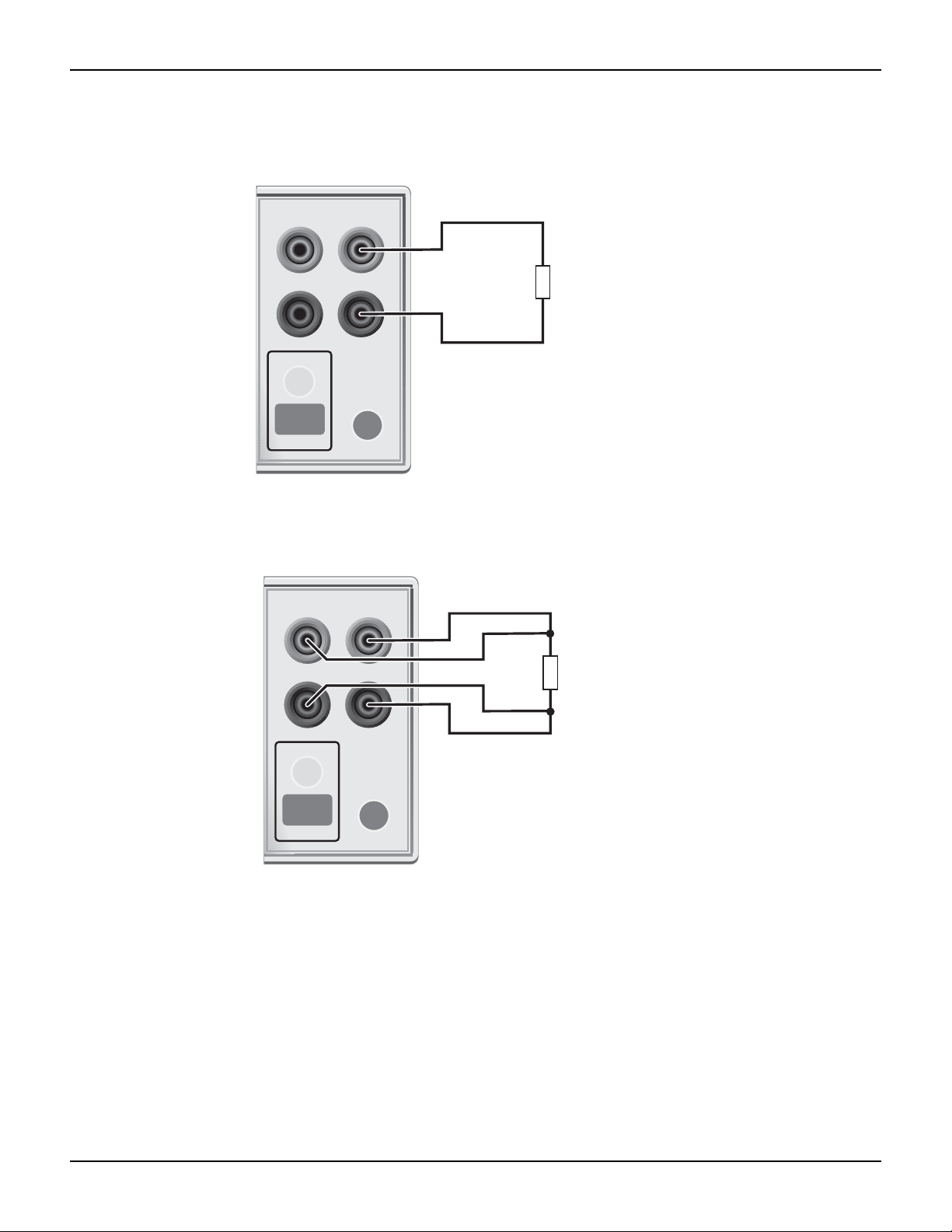
2-wire connections
Connections for 2-wire local sensing are shown in Figure 3. The followin g menu sequ ence select s
2-wire local sensing:
Press CONFIG > select SOURCE V (or ΜΕ ΑS Ω) > select SENSE MODE > select 2-WIRE
1-6 Return to Section Topics 2400S-903-01 Rev. E / September 2011
Page 14
Series 2400 SourceMeter® Quick Start Guide Section 1: Introduction
HI
LO
OUTPUT
INPUT/
OUTPUT
4-WIRE
SENSE
ON/OFF
TERMINALS
FRONT/
REAR
DUT
SourceMeter Front Panel
Sense Selection: 2-wire
FRONT/
REAR
HI
LO
OUTPUT
INPUT/
OUTPUT
4-WIRE
SENSE
ON/OFF
TERMINALS
FRONT/
REAR
DUT
SourceMeter Front Panel Sense Selection: 4-wire
FRONT/
REAR
Figure 1-3
2-wire connections
Figure 1-4
4-wire connections
4-wire connections
Connections for 4-wire local sensing are shown in Figure 4. Use 4-wire remote sensing for the
following source-measure conditions:
• Test circuit impedance is <1kΩ.
• Optimum ohms, V-source, and/or V-measure accuracy is required.
With 4-wire sensing selected, the 4W annunciator is o
wire remote sensing:
n. The following menu sequence selects 4-
2400S-903-01 Rev. E / September 2011 Return to Section T o pics 1-7
Press CONFIG > select SOURCE V (or MEAS Ω) > select SENSE MODE > select 4-WIRE
Page 15

Section 1: Introduction Series 2400 SourceMeter® Quick Start Guide
INPUT/
OUTPUT
4-WIRE
SENSE
HI
LO
IEEE-488
(ENTER IEEE ADDRESS
WITH FRONT PANEL MENU)
V, Ω
GUARD
GUARD
SENSE
WARNING:NO INTERNAL OPERATOR SERVICAB
CAUTION:FOR CONTINUED PROTECTION AGAINST FIR
RS232
DUT
Connect to earth safety ground
using #18 AWG wire or larger.
Guard Shield
Test Fixture
Figure 1
Cable guard connections
NOTE Specified accuracies for both source and measure are achieved only
using 4-wire remote sensing.
Cable guard
When testing high-impedance DUT (>1GΩ), cable guard is used to drive the shields of cables and
test fixtures to minimize leakage currents and input capacitance. A typical connection scheme
using cable guard is shown in Figure 5. The following menu sequence select s cable guard:
Press CONFIG > press SOURCE V (or
The guard terminal of the SourceMeter is at virtually
SOURCE I or MEAS Ω) > select GUARD > select CABLE
the same potential as input/output HI.
Therefore, if there is hazardous voltage at input/outpu t HI, it is also present on the gu ard shield for
the test circuit.
WARNING To prevent injury from electric shock, the guard shield must be
enclosed in a safety shield (i.e., test fixture) that is connected to
safety earth ground (as shown in Figure 5).
1-8 Return to Section Topics 2400S-903-01 Rev. E / September 2011
Page 16

Series 2400 SourceMeter® Quick Start Guide Section 1: Introduction
INPUT/
OUTPUT
4-WIRE
SENSE
HI
LO
IEEE-488
(ENTER IEEE ADDRESS
WITH FRONT PANEL MENU)
V, Ω
GUARD
GUARD
SENSE
WARNING:NO INTERNAL OPERATOR SERVICAB
CAUTION:FOR CONTINUED PROTECTION AGAINST FIR
RS232
DUT
Connect to earth safety ground
using #18 AWG wire or larger.
Guard Shield
Test Fixture
Figure 1-5
Cable guard connections
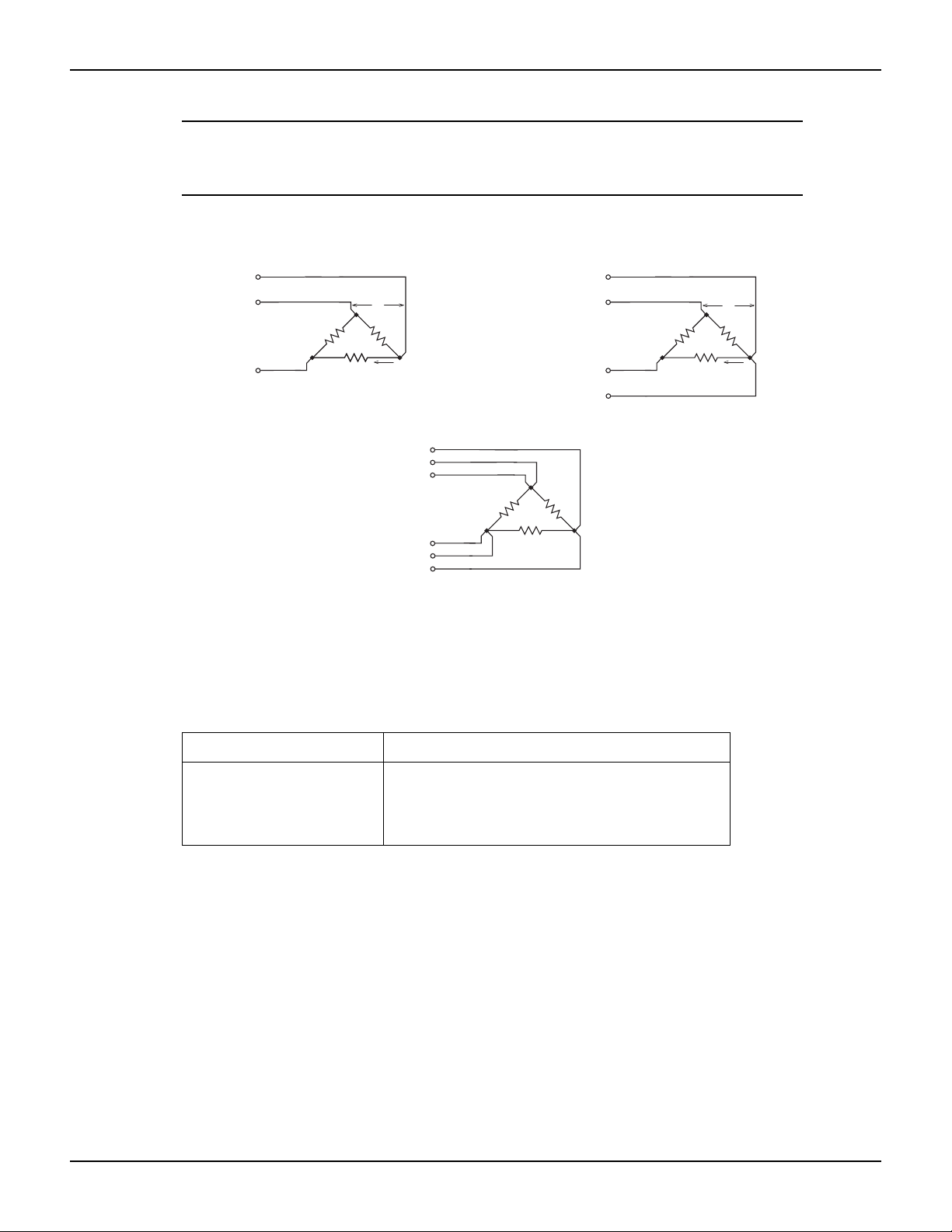
Ohms guard
Ohms guard allows in-circuit resistance measurements on DUT where other parasitic leakage
devices are present. Connection schemes for a Delta DUT configuration is shown in Figure 6.
NOTE Ohms guard cannot be used for high current (>100mA) ranges.
Ohms guard cannot be selected if already on a high current range.
Conversely, if ohms guard is already selected, a high current ra nge
The following menu sequence selects ohms guard:
Press CONFIG > press MEAS Ω (or SOURCE V or SOURC
Basic connections for ohms guard is shown in Figure 6A. With V, Ω Guard and In/Out HI at virtually
the same potential,
be 0A. Virtually all the current from In/Out HI will flow through the DUT resulting in an accurate
measurement.
If the guard resistance path (R
such that a significant voltage drop appears across R. The resultant leakage current through R will
corrupt the measurement of the DUT.
Guard Sense is used to cancel the ef
6B. Guard Sense regulates the guard voltage to ensure that the same potential appears on either
2400S-903-01 Rev. E / September 2011 Return to Section T o pics 1-9
side of R.
For DUT <1kΩ, 4-wire sensing should be used as shown in Figure 6C.
cannot be selected.
the voltage drop across R will be 0V, and therefore, the current through R will
E I) > select GUARD > select OHMS
) is <1kΩ, IR drop in the V , Ω Guard test lead could be high enough
G
fect of IR drop in the V, Ω Guard test lead as shown in Figure
Page 17
Section 1: Introduction Series 2400 SourceMeter® Quick Start Guide
DUT
V, Ω Guard
Sense HI
In/Out HI
In/Out LO
Sense LO
Guard Sense
Sense Mode: 4-wire
C. 6-wire connections
DUT
V, Ω Guard
In/Out HI
In/Out LO
Sense Mode: 2-wire
A. Basic connections
DUT
V, Ω Guard
In/Out HI
In/Out LO
Guard Sense
Sense Mode: 2-wire
B. Connections using guard sense
<1kΩ
RG
IG
≥1kΩ
RG
IG
R
0V
R
0V
NOTE Guard current (IG) must never exceed 50mA. If it does, guard voltage
will become less than the output voltage and corrupt the
measurement.
Figure 1-6
Guarded ohms measurements
Basic SourceMeter operations
Remote command programming
Table 1 lists the SCPI commands to select terminals, sense, and cable guard.
Table 1-1
SCPI commands; terminals, sense, and cable guard
Command Description
:ROUTe:TERMinals <name> Selects terminals; <name> = FRONt or REAR.
:SYSTem:RSENse <b> Selects sense mode; <b> = ON (4-wire) or OFF (2-
:SYSTem:GUARd <name> Selects guard mode; <name> = CABLe or OHMS.
Fundamental SourceMeter operations include source- measure, measure only (V or I) and
measure ohms.
Source-measure
There are four source-measure combinations for the SourceMeter:
Source V, Measure I
Source I, Measure V
Source V, Measure V
Source I, Measure I
The basic procedure to source-measure is p rovided in Table 2. It assumes that the DUT is already
connected
to the SourceMeter as explained in Basic connections.
wire).
1-10 Return to Section Topics 2400S-903-01 Rev. E / September 2011
Page 18

Series 2400 SourceMeter® Quick Start Guide Section 1: Introduction
Table 1-2
Source-measure procedure
Procedure Details
1. Select source function. Press SOURCE V or SOURCE I.
2. Set source level. Use DISPLAY EDIT key to place cursor in source
field (Vsrc or Isrc), use RANGE
select range, use edit keys to key in source
value, then press ENTER.
3. Set compliance limit. Use DISPLAY EDIT key to place cursor in Cmpl
field, use RANGE arrow keys to select range, use
edit keys to key in limit value, then press ENTER.
4. Select measurement function. Press MEAS V or MEAS I.
arrow keys to
5. If not measuring the source, select
measure range or use auto range (see
Notes 1 and 2).
6. Turn output on and take readings
from display.
7. Turn output off when finished. Press ON/OFF OUTPUT key. Red OUTPUT indi-
Notes:
1. When measuring source (i.e., Source I, Measure I), you
enable auto range. The measure range is determined by the source range.
2. When not measuring the source (i.e., Source I, Measur
maximum measurement range that can be selected.
Sink operation
When operating as a sink (V and I have opposite polarity), the SourceMeter is dissipating power
rather than sourcing it. An external source can force operation into the sink region. The
SourceMeter can be used to charge/discharge (source/sink) batteries. For oper ation information
on battery charging/discharging (and the associated precautions), see Section 3, Sink operation
of the 2400 Series SourceMeter User’s Manual.
Measure only (V or I)
Use RANGE arrow keys to manually select
range. Or press AUTO RANGE (AUTO annunciator on) to enable auto range.
Press ON/OFF OUTPUT key. Red OUTPUT indicator on.
cator off.
cannot change the measure range or
e I), the compliance range determines the
The SourceMeter can be used to measure voltage only (voltmeter) or current only (ammeter). The
procedure to measure only is provided in Table 3.
2400S-903-01 Rev. E / September 2011 Return to Section T o pics 1-11
Page 19

Section 1: Introduction Series 2400 SourceMeter® Quick Start Guide
Table 1-3
Measure only (V or I) procedure
Procedure Details
1. Select source-measure
functions.
2. Set source level to zero. Use DISPLAY EDIT key to place cursor in source field
3. Set compliance higher
than the expected measurement (see CAUTION 1).
4. Select measurement
range (see Note).
5. Connect voltage or cur-
rent to be measured.
6. Turn output on and take
reading from display.
7. Turn output off when
finished.
Note:When measuring current, auto range can be used. When measuring voltage, DO NOT use auto
range (see CAUTION 2).
To measure voltage, press SOURCE I and MEAS V. To
measure current, press SOURCE V and MEAS I.
(Vsrc or Isrc), use RANGE down arrow key to select lowest range, press MENU to display zero source level, then
press ENTER.
Use DISPLAY EDIT key to place cursor in Cmpl field, use
RANGE arrow keys to select range, use edit keys to key in
compliance value, then press ENTER.
Use RANGE arrow keys to select a fixed measurement
range. For best accuracy, use the lowest possible range.
Connect DUT to SourceMeter using 2-wire connections
(see Figure 3).
Press ON/OFF OUTPUT key. Red OUTPUT indicator on.
Press ON/OFF OUTPUT key. Red OUTPUT indicator off.
CAUTION When using the SourceMeter as a voltmeter only, voltage compliance must
CAUTION When using the SourceMeter as a voltmeter only, DO NOT use auto range
Measure ohms
Measurement methods
There are two methods to measure resistance; auto ohms and manual ohms. In auto ohms, the
SourceMeter operates as a conventional constant-cu rrent sour ce ohmmeter. You simply select an
ohms measurement range (or auto range) and t ake the reading from the display.
In manual ohms, the SourceMeter uses the V/I meas
(V or I) and selecting a voltage or current measurement range, the Ω measurement function will
splay the calculated V/I ohms reading.
di
be set higher than the voltage that is being measure d. Failure to do so
could result in instrument damage due to excessive current that will flow
into the SourceMeter.
and NEVER select a measurement range that is below the applied signal
level. Otherwise, high current drawn from the external source could
damage the external source or the test circuit.
urement method. After configuring the sour ce
1-12 Return to Section Topics 2400S-903-01 Rev. E / September 2011
Page 20

Series 2400 SourceMeter® Quick Start Guide Section 1: Introduction
Use the following menu sequence to select the auto ohms or ma nua l oh ms meas ure ment metho d:
Press CONFIG > press MEAS Ω > select SOURCE > select AUTO or MANUAL
Ohms source readback
With source readback enabled, the SourceMeter measures both V and I and uses these values for
the ohms calculation. This feature provides optimum accuracy for front panel operation since the
measured source value is more accurate than the programmed source value. For remote
operation, the user specifies the functions to measure.
Use the following menu sequence to enable or disable source readback:
Press CONFIG > press MEAS Ω > select SRC RDBK > select ENABLE or DISABLE
Ohms measurement procedures
The auto ohms and manual ohms measurement procedures are provided in Tables 4 and 5. They
assume that the DUT is already connected to the SourceMeter . (See Basic con nections.) Note that
resistance accuracy specifications are based on 4-wire sensing.
Table 1-4
Auto ohms measurement procedure
Procedure Details
1. Select ohms measurement
function.
2. Select auto ohms
measurement method.
3. Select measurement range. Use RANGE arrow keys to manually select
4. Turn output on and take
readings from display.
5. Turn output off when finished. Press ON/OFF OUTPUT key. Red OUTPUT
Press MEAS Ω.
Press CONFIG > press MEAS Ω > select
SOURCE > select AUTO.
range. Or press AUTO RANGE (AUTO
annunciator on) to enable auto range.
Press ON/OFF OUTPUT key. Red OUTPUT
indicator on.
indicator off.
Table 1-5
Manual ohms measurement procedure
Procedure Details
1. Select ohms measurement
function.
2. Select manual ohms measure-
ment method.
3. Select source, set source level,
and set compliance limit.
4. Select measurement range (see
Notes 1 and 2).
5. Turn output on and take readings
from display.
6. Turn output off when finished. Press ON/OFF OUTPUT key. Red OUTPUT indi-
Notes
1. If sourcing I, you will be selecting the V measure range. If sour
measure range.
2. The compliance range determines the maximum measurement range that can be selected.
2400S-903-01 Rev. E / September 2011 Return to Section T o pics 1-13
Press MEAS Ω.
Press CONFIG > press MEAS Ω > select SOURCE
> select MANUAL.
See steps 1, 2, and 3 of Table 2.
Use RANGE arrow keys to manually select range.
Or press AUTO RANGE (AUTO annunciator on) to
enable auto range.
Press ON/OFF OUTPUT key. Red OUTPUT indicator on.
cator off.
cing V, you will be selecting the I
Page 21

Section 1: Introduction Series 2400 SourceMeter® Quick Start Guide
Offset-compensated ohms
Thermal EMFs can corrupt low-resistance measurements. An offset-compensated Ω
measurement cancels out unwanted offset by performing the following 2-point measurement
process:
Offset-Compensated Ω = ΔV / ΔI
where:ΔV = V2 - V1
ΔI = I2 - I1
V1 and I1 are V and I measurements with the source set to a specific level.
V2 and I2 are V and I measurements with the source set to zero .
1. Select the Ω function, and select the auto or manual ohms measurement method.
2. Enable offset compensation by using the following menu sequence:
3. Press CONFIG > press MEAS Ω > select OFFSET COMPENSATION > select ENABLE
4. If using auto ohms, go to the next step. For manual ohms, configure the desired source (V
or I) to output an appropriate source leve l. Set compliance and select a measurement range
(or use auto range).
5. Turn the output on and observe the offset-compensated ohms reading on the display. Note
that the source value alternates between the set output level and zero.
6. When finished, turn the output off and disable offset compensation.
NOTE Manual offset-compensated ohms is also available as a math
function (FCTN). This math function allows you to specify both source
levels (see “Math functions” in “Features to enhance DUT testing.”
In-circuit ohms measurements
Ohms guard allows you make accurate in-circuit ohms measurements on resistor networks. These
measurements are covered in Advanced operation.
Remote command programming
Data string
The :READ? command is typically used to trigger a source-measure action and request the data
string. The data string is sent to the computer when the SourceMeter is addressed to talk.
The data string is typically made up of five element
the voltage reading, the second is the current reading, and the third is the resistance reading. For
voltage and current, the reading could be source or measure depending on how the instrument is
configured. For example, if sourcing voltage and measuring curren t, the voltage element is the
source reading and the current element is the measured reading. The NAN (not a numb er) value
of +9.91e37 is used for a function that is not enabled.
The fourth data element is the timestamp and the
subsystem, of the 2400 Series SourceMeter User’s Manual for details on all aspects of the data
format.
s separated by commas. The first element is
fif
th is the status word. See Section 18, FORMat
1-14 Return to Section Topics 2400S-903-01 Rev. E / September 2011
Page 22

Series 2400 SourceMeter® Quick Start Guide Section 1: Introduction
NOTE The five element data string is the GPIB default cond itio n.
SCPI commands
SCPI commands to source-measure and measure only are provided in Table 6, and the
commands to measure ohms are provided in Table 7.
Table 1-6
SCPI commands; source-measure and measure only
Command
2
Description
1
:SOURce:FUNCtion <name> Select source function; <name> = VOLTage or CURRent.
:SOURce:xxx:MODE FIXed Select fixed V or I sourcing mode.
:SOURce:xxx:RANGe <n> Select measurement range for V or I source; <n> = range.
:SOURce:xxx:LEVel <n> Set source amplitude; <n> = amplitude in volts or amps.
[:SENSe]:FUNCtion <name> Select measure function; <name> = “VOLTage” or “CUR-
Rent”.
[:SENSe]:xxx:PROTection <n> Set V or I compliance; <n> = compliance.
[:SENSe]:xxx:RANGe <n> Select V or I measure range; <n> = range.
[:SENSe]:xxx:RANGe:AUTO
Enable or disable auto range; <b> = ON or OFF.
<b>
:OUTPut <b> Turn output on or off; <b> = ON or OFF.
:READ? Trigger and acquire one data string.
1. For measure only, the following rules apply (Table 9 provides an example to measure I only):
a. To measure V only, you must source I. To measure I only
b. The source must be set to 0V or 0A.
c. When measuring V only, DO NOT use auto range.
d. When measuring V only, voltage compliance MUST be set higher th
2. :xxx = :VOLTage or :CURRent.
, you must source V.
an the volt
age being measured.
Table 1-7
SCPI commands; measure ohms
Command Description
[:SENSe]:FUNCtion “RESistance” Select ohms function.
[:SENSe]:RESistance:MODE <name> Select ohms mode; <name> = AUTO or MANual*.
[:SENSe]:RESistance:OCOMpensated
Enable/disable offset compensation.
<b>
[:SENSe]:RESistance:RANGe <n> Select range for auto ohms; <n> = range.
[:SENSe]:RESistance:RANGe:AUTO
<b>
:OUTPut <b
> Turn output on or off; <b> = ON or OFF.
Enable or disable auto range for auto ohms; <b> =
ON or OFF.
:READ? Trigger and acquire one data string.
*For manual ohms, you must configure the SourceMeter to source-measure. T able 11 provides a programming
example to measure ohms using the manual ohms method.
Programming examples
Source-measure example — Table 8 shows a typical command sequence to source 10V and
measure current on the 10mA range.
2400S-903-01 Rev. E / September 2011 Return to Section T o pics 1-15
Page 23

Section 1: Introduction Series 2400 SourceMeter® Quick Start Guide
Measure-only example — Table 9 shows a typical command sequence to measure current only.
Table 1-8
Command sequence for source-measure example
Command* Comments
*RST Restore GPIB defaults (one-shot source-measure
mode).
:SOUR:FUNC VOLT Select voltage source function.
:SOUR:VOLT:MODE FIX Select fixed voltage source mode.
:SOUR:VOLT:RANG 20 Select 20V source range.
:SOUR:VOLT:LEV 10 Set source output level to 10V.
:SENS:FUNC “CURR” Select current measurement function.
:SENS:CURR:PROT 10e-3 Set compliance limit to 10mA.
:SENS:CURR:RANG 10e-3 Select the 10mA measurement range.
:OUTP ON
Turn the output on.
:READ? Trigger and acquire one data string.
*SourceMeter must be addressed to talk after sending :READ? to trigger and acquire data.
Table 1-9
Command sequence for measure current only example
Command* Comments
*RST Restore GPIB defaults (one-shot measure mode).
:SOUR:FUNC VOLT Select voltage source function.
:SOUR:VOLT:MODE FIX Select fixed voltage source mode.
:SOUR:VOLT:RANG 0.2 Select 200mV source range.
:SOUR:VOLT:LEV 0 Set source output level to 0.000mV.
:SENS:FUNC “CURR” Select current measurement function.
:SENS:CURR:PROT 100e-3 Set compliance limit to 100mA.
:SENS:CURR:RANG 10e-3 Select the 10mA measurement range.
:OUTP ON
:READ? Trigger and acquire one data string.
*SourceMeter must be addressed to talk after sending :READ? to trigger and acquire data.
Turn the output on.
Auto ohms example — Table 10 shows a typical command
sequence to use auto ohms to
measure resistance. Note that 4-wire sensing is used for this example. See Basic connections for
details on sensing.
Manual ohms example — Table 11 shows a typical command sequence to use manual ohms to
measur
e resistance. This example uses auto range for current measurements. If you were to use
manual ranging, you should select the lowest possible current rang e for the measurement. For
example, to measure a 1MΩ resistor with the source set to 2V, the 1µA measure range should be
cted
sele
ex
1-16 Return to Section Topics 2400S-903-01 Rev. E / September 2011
to achieve the best accuracy (2V/1µA = 2MΩ). Note that 2-wire sensing is used for this
ample. See Basic connections for details on sensing.
Page 24

Series 2400 SourceMeter® Quick Start Guide Section 1: Introduction
Table 1-10
Command sequence for auto ohms example
Command* Comments
*RST Restore GPIB defaults (one-shot measurement mode).
:SENS:FUNC “RES” Select ohms measurement function.
:SENS:RES:RANG 200 Select 200Ω range.
:SENS:RES:MODE AUTO Select the auto ohms measurement method.
:SYST:RSEN ON Select 4-wire sense mode.
:OUTP ON
:READ? Trigger and acquire one data string.
*SourceMeter must be addressed to talk after sending :READ? to trigger and acquire data.
Turn the output on.
Table 1-11
Command sequence for manual ohms example
Command* Comments
*RST Restore GPIB defaults (one-shot measurement mode).
:SENS:FUNC “RES” Select ohms measurement function.
:SENS:RES:MODE MAN Select the manual ohms measurement method.
tion.
:SOUR:FUNC VOLT Select voltage source fun
:SOUR:VOLT:MODE FIX Select fixed voltage sourcing mode.
:SOUR:VOLT:RANG 2 Select 2V source range.
:SOUR:VOLT:LEV 2 Set source level to 2V.
:SENS:CURR:PROT 10e-3 Set current compliance to 10mA.
:SENS:CURR:RANG:AUTO ONSelect auto range for current measurements.
c
:SYST:RSEN OFF Select 2-wire sense mode.
:OUTP ON
:READ? Trigger and acquire one data string.
*SourceMeter must be addressed to talk after sending :READ? to trigger and acquire data.
Turn the output on.
Settings to optimize performance
Range
To achieve best accuracy, the SourceMeter should be on the lowest possible measurement range.
In most situations, auto range can be used to automatically select the best range. Auto range is
controlled (enabled/disabled) by the AUTO rang e key (AUTO annunciator indicates auto range is
enabled).
RANGE
disables auto range.
arrow keys are used for manual range selection. Note that pressing either of these keys
NOTE Basic ranging information (including the SCPI commands for remote
operation) is covered in “Fundamental source- measure operations.”
2400S-903-01 Rev. E / September 2011 Return to Section T o pics 1-17
Page 25

Section 1: Introduction Series 2400 SourceMeter® Quick Start Guide
Speed
Measurement speed is set by setting the integration time of the A/D converter (period of time the
input signal is measured). Integration time affect s the usable digits, readin g noise, and the ultimate
reading rate of the instrument. It is specified in parameters based on the number of power line
cycles (NPLC), where 1 PLC for 60Hz is 16.67msec (1/60), and 1 PLC for 50Hz and 400Hz is
20msec (1/50).
Digits
In general, the fastest speed setting (FAST; 0.01 PLC) results in increased
display digits. The slowest speed (HI ACCURACY; 10 PLC) provides the best commo n- mod e and
normal-mode noise rejection. In between settings are a compromise between speed and noise.
Press SPEED and select one of the followi
FAST Sets speed to 0.01 PLC and display resolution to 3H-digits.
MED Sets speed to 0.10 PLC and display resolution to 4H-digit
NORMAL Sets speed to 1.00 PLC and display resolution to 5H-digit
HI ACCURACY Sets speed to 1.00 PLC and display resolution to 5H-digit
OTHER Use to set speed to any PLC value from 0.01 to 10. Display reso-
lution is not changed after speed is set with this option.
NOTE After setting speed, display resolution can be changed using the
DIGITS key.
The SourceMeter can display readings at 3H-digit, 4H-digit, 5H-digit or 6H-digit resolution. In situations
where the last digits of the reading are noisy, you can turn those digits off by decreasing display
resolution.
ng speed setting options:
noise and fewer usable
s.
s.
s.
Filter
To set display resolution, press the
Another way to set display resolution is with the following menu sequence:
Press CONFIG > press DIGITS > select 3.5, 4.5, 5.5, or 6.5.
NOTE Changing DIGITS does not affect measurement SPEED, but
changing measurement speed does affect DIGITS.
Filtering is used to stabilize noisy readings. In general, the more filtering that is applied, the more
stable (and accurate) the reading. However, more filtering also means slower speed.
The filtering process consists of filling a stack wi
(filter count), and then averaging them to yield a filtered reading. The SourceMeter has two filter
types; moving and repeating.
DIGITS key until the desired number of digits are displayed.
th the specified number of reading conversions
Repeating filter
The stack is filled with the specified number of reading conversions. The reading conversions are
averaged to yield a filtered reading. The stack is then cleared, and the process starts over. Use
this filter for sweeping so readings for other source levels are not averaged with the present
source level.
1-18 Return to Section Topics 2400S-903-01 Rev. E / September 2011
Page 26

Series 2400 SourceMeter® Quick Start Guide Section 1: Introduction
Moving filter
The first reading conversion is placed in the stack, and is copied to the other stack locations to fill
it. Therefore, the first filtered reading is the same as the first reading conversion. The stack type is
first-in, first-out. Each subsequent conversion replaces one of the copied readings in the stack,
which is then averaged to yield the next filtered reading. Note th at as this process continues, a true
average is not yielded until the stack is filled with new reading conversions (no copies in stack).
Once the stack is filled, each subsequent conversion placed into the st
conversion. The stack is re-averaged, yielding a new filtered reading.
Response time
Filter type and count have the following effects on the time needed to display, store, or output a
filtered reading:
• Filter type: The moving filter type yields faster filtered readings
the entire stack (as is the case for the repeating filter) .
• Filter count: Speed and accuracy are trade-of
filtering to achieve acceptably stable readings.
Filter configuration
Filter type — Use the following menu sequence to select filter type:
Press CONFIG > press FILTER > select AVERAG
Filter count — Us
Press CONFIG > press FILTER > select AVERAG
Rel (nulling offsets)
The rel (relative) feature allows you to null offsets. With the offset displayed (measure d) , en ab lin g
rel acquires the offset reading as the rel value and zeroes the display as follows:
ack replaces the oldest
since it doesn’t have to re-fill
fs. T
ypically , you will want to apply just enough
E MODE > select MOVING or REPEAT
e the following menu sequence to select the amount of filtering:
E COUNT, set count value (1 to 100)
Displayed Reading = Actual Input - Rel Value
Since the actual input (offset) and the rel value are th
Rel is enabled by pressing the REL key (REL annunciator on). Pressing REL a second time
disa
bles it. Perform the following steps to null out an offset:
1. Connect your test circuit
2. Select the source function that you are going to use for your test.
3. Select the lowest source range and set the source level to zero.
4. Select the measure function that you are going to use for your test, and select the lowest
range.
5. Turn the output on to measure the offset.
6. With the offset reading displayed, press REL (REL annunciator on) to zero the display. Turn
the output off and configure the selected source and measure functions for your test.
7. Turn the output back on. The displayed test readings will not include the nulled offset.
8. When finished, turn the output off.
If the offset drifts, disable rel and repe at the above procedure to null out the new offset.
2400S-903-01 Rev. E / September 2011 Return to Section T o pics 1-19
to the SourceMeter.
e same, the displayed reading is zero.
Page 27

Section 1: Introduction Series 2400 SourceMeter® Quick Start Guide
NOTE Rel can also be used to establish a baseline reading. The baseline
reading will be subtracted from present and future readings. See
“Relative” in Section 8 of the 2400 Series SourceMeter User’s
Manual for details.
Remote command programming
The SCPI commands for speed, digits, filter, and rel are listed in Table 12. The commands for
ranging are listed in Tables 6 and 7.
Table 1-12
SCPI commands; speed, digits, filter, and rel
Command Description
1
Speed commands
[:SENSe]:CURRent:NPLCycles <n> Set measurement speed; <n> = 0.01 to 10.
[:SENSe]:VOLTage:NPLCycles <n> Set measurement speed; <n> = 0.01 to 10.
[:SENSe]:RESistance:NPLCycles
<n>
:
Set measurement speed; <n> = 0.01 to 10.
Digits command:
:DISPlay:DIGits <n> Set display resolution; <n> = 4, 5, 6, or 7.
Filter commands:
[:SENSe]:AVERage:TCONtrol
<name>
[:SENSe]:AVERage:COUNt <n> Set filter count; <n> = 1 to 100.
[:SENSe]:AVERage <b> Enable/disable filter; <b> = ON or OFF.
2
Rel command
:CALCulate2:NULL:STATe <b> Enable/disable rel; <b> = ON or OFF.
1. The speed setting is global for all functions. Therefore, you can use any of the three commands to set speed.
1. The commands to acquire a rel value are not listed in this table (see Section 8, Relative in
t
he 2400 Series SourceMeter User’s Manual).
:
Features to enhance DUT testing
Data store
The data store (buffer) can store from 1 to 2500 readings, and provides statistical data on the
stored readings.
Select filter type; <name> = REPeat or MOVing.
Storing readings
To store readings, press STORE, key in the number of readings to store, and press ENTER. The
star (*) annunciator indicates that the buffer is enabled. To start the storage process, turn the
output on and (if necessary) trigger the unit. The star (*) annunciator turns off after storage is
completed.
1-20 Return to Section Topics 2400S-903-01 Rev. E / September 2011
Page 28

Series 2400 SourceMeter® Quick Start Guide Section 1: Introduction
Recalling readings
To recall readings, press the RECALL key. The buffer location number is the memory location of
the recalled reading. Location #0000 indicates that the displayed reading is stored at the first
memory location. To display other stored readings, use the edit keys to change the buffer location
number. To exit from the recall mode, press EXIT.
Timestamp — Just
below the buffer location number is the timestamp (in seconds) for the
reading. It can be referenced to the first reading stored in the buf fer ( absolute tim estamp ), or it ca n
indicate the time between buffer readings (delt a timestamp). If the absolute timestamp is selected,
the @ symbol precedes the timestamp value. If the delta timestamp is selected, the δ symbol
r
ecedes the timestamp value. Regardless of which timestamp is selected , the first reading is
p
always timestamped at zero seconds.
To change the timestamp, exit from the recall mode
Press CONFIG > press STORE > select ABSOLUTE or DEL
and use the following menu sequence:
TA
NOTE While in the recall mode, buffer statistics (minimum, maximum, peak-
to-peak, average and standard de viati on) can be displa yed u sing the
TOGGLE key . Details about buffer statistics are provided in Section 9
of the 2400 Series SourceMeter User’s Manual.
Remote command programming
SCPI commands
SCPI commands to configure and control the buffer are listed in Table 13.
NOTE Table 13 does not provide a complete listing of buffer commands.
Documentation for all buffer commands (including the ones for buffer
statistics) can be found in Section 9 of the 2400 Series SourceMeter
User’s Manual.
Table 1-13
SCPI commands; data store
Command Description
:TRACe:POINts <n> Specify buffer size; <n> = 1 to 2500
:TRACe:FEED <name> Specify reading source; <name> = SENSe (raw
ing
s), CALCulate (math readings), or
read
CALCulate2 (limits readings).
:TRACe:TSTamp:FORMat <name> Select timestamp format;
DELTa.
:TRACe:FEED:CONTrol <name> Enable/disable buffer; <name> = NEXT (fill buffer
stop) or NEVer (disable buffer).
and
:TRACe:DATA? Read contents of buffer.
:TRACe:CLEar Clear buffer.
2400S-903-01 Rev. E / September 2011 Return to Section T o pics 1-21
<name> = ABSolute
or
Page 29

Section 1: Introduction Series 2400 SourceMeter® Quick Start Guide
Programming example
Table 14 shows a typical command sequence to store and recall readings from the buffer.
Table 1-14
Command sequence for data store example
Command* Comments
*RST Restore GPIB defaults.
:SOUR:VOLT 10 Set voltage source to 10V.
:TRAC:POINts 10 Set buffer size to 10.
:TRIG:COUN 10 Trigger count equals number of readings.
:TRAC:FEED SENS Set to store raw readings.
:TRAC:FEED:CONT NEXT Enable buffer.
:OUTP ON Turn on output.
:INIT Trigger readings.
:TRAC:DATA? Request raw buffer readings.
*SourceMeter must be addressed to talk after sending :TRAC:DATA? to acquire data.
Sweep operation
Sweep types
The four available sweep types are linear staircase, logarithmic staircase, custom, and source
memory.
Linear staircase sweep
When the sweep shown in Figure 7 is triggered to start, the output w
source level. The bias level is the initial source level prior to the start of the sweep. The output will
then change in equal steps until the stop source level is reached . With trigger delay set to zero, the
time duration at each step is determined by the source delay and the time it takes to perform the
measurement.
With the desired source (V or I) selected, use the follo
and step source levels:
Press CONFIG > press SWEEP > select TYPE > select
After selecting STAIR, you will be prompted to enter the STAR
ill go from the bias level to the
win
g menu sequence to set the start, stop
STAIR
T, STOP and STEP levels.
1-22 Return to Section Topics 2400S-903-01 Rev. E / September 2011
Page 30

Series 2400 SourceMeter® Quick Start Guide Section 1: Introduction
Delay
Delay
Delay
Delay
Start
Bias
Stop
Step
Step
Step
Measure Measure Measure Measure
X = Measurement point
X
X
X
X
Figure 1-7
Linear staircase sweep
Logarithmic staircase sweep
This sweep is similar to the linear staircase sweep. The steps, however, are done on a logarithmic
scale. The symmetrical log
points for the steps are determined by the specified number of sweep
points. Figure 8 shows a 5-point log sweep from 1 to 10V.
With the desired source (V or I) selected, use the following menu sequence to set the start and
stop levels, and
Press CONFIG > press SWEEP > select TYPE > select
After selecting LOG, you will be prompted to enter the STAR
the number of sweep points (2 to 2500):
LOG
T and STOP levels, and the NO OF
POINTS.
2400S-903-01 Rev. E / September 2011 Return to Section T o pics 1-23
Page 31

Section 1: Introduction Series 2400 SourceMeter® Quick Start Guide
Delay
Delay
Delay
Delay
Start
Bias
Stop
(10)
Measure
#1
Measure
#2
Measure
#3
Measure
#5
X = Measurement Point
X
X
X
X
Delay
X
Measure
#4
Log Points = 5
1
10
5.6234
3.1623
1.7783
Volts
Log
Scale
Figure 1-8
Logarithmic staircase sweep (example)
Custom sweep
For a custom sweep, the user specifies the number o
f point in a sweep, and the source level at
each point. Figure 9 shows a 6-point, 50% duty cycle pulse sweep. The specified voltage level at
points P0, P2 and P4 is 1V, while the voltage level at P1, P3 and P5 is 0V.
With the desired source (V or I) selected, use the fo
llowing menu sequence to specify the number
of sweep points and the source level at each point:
Press CONFIG > press SWEEP > select TYPE > select
After selecting CUSTOM, these menu items will be
# POINTS - Use to specify the number of points in the sweep (1 to 2500)
ADJUST POINTS - Use to set the source level at each point in t
sweep is P0000. After setting the level for P0000, incr ement the pointer to P0001 and set the level
for that point. In a similar manner, set the level for each point in the sweep.
INIT - This option allows you to set a consecutive rang
selecting INIT, you will be prompted to enter the source VALUE, the START PT (point), and the
STOP PT (point). For example, if you want points 10 through 15 to be 1V, set VALUE to 1V, START
CUSTOM
displayed:
he sweep. The first point in the
e of sweep points to a specified level. After
PT to 10, and STOP PT to 15.
1-24 Return to Section Topics 2400S-903-01 Rev. E / September 2011
Page 32

Series 2400 SourceMeter® Quick Start Guide Section 1: Introduction
Delay
P1
Measure
#1
P0
Measure
#2
Delay
Delay
P3
Measure
#3
P2
Measure
#4
Delay
Delay
P5
Measure
#5
P4
Measure
#6
Delay
Bias 0V
1V
Bias
Figure 1-9
Custom pulse sweep (example)
Source memory sweep
For a source memory sweep, up to 100 setup configurations can be saved in memory. When the
sweep
is run, the setup at each memory point is recalled. This allows multiple functions and math
expressions to be used in a sweep.
A SourceMeter setup configuration is saved in memor
y by performing the following menu
sequence:
Press MENU > select SAVESETUP > select SO
After selecting SAVE, you will be prompted to enter the memory loc
URCE MEMORY > select SAVE
ation where you want to store
the setup.
After saving all your test setups in concurrent memor
y locations, use the following menu sequence
to configure the sweep:
Press CONFIG > press SWEEP > select TYPE >
After selecting SRC MEMORY, the followi
ng menu items will be displayed:
START - Use this menu item to set the starting memory location
select SRC MEMORY
for the sweep. For example, if
your first setup is stored in memory location 001, set the start point to 001.
# POINTS - Use to specify the number of points (memor
y locations) in the sweep. For example, if
there are 10 points in the sweep, set the number of points to 010.
NOTE NPLC caching can be used to speed up source memory sweeps. See
“NPLC caching” in Section 3 of the 2400 Series User’s Manual.
Sweep count
For front panel operation, a sweep can automatically repeat a specified number of times (finite
sweep count) or it can repeat continuously (infinite sweep count).
For a finite count sweep, the readings ar
e automatically stored in the buffer . The maximum numbe r
of finite sweeps that can be performed is determined as follows:
Maximum finite sweep count = 2500 /
For an infinite sweep count, the readings are no
Use the following menu sequence to set sweep count:
Press CONFIG > press SWEEP > select SWEEP COUNT > select FINITE or
# points in sweep.
t stored in the buffer.
INFINITE
If you select FINITE, you will be prompted to enter the sweep count.
2400S-903-01 Rev. E / September 2011 Return to Section T o pics 1-25
Page 33

Section 1: Introduction Series 2400 SourceMeter® Quick Start Guide
Source ranging
There are three options to control source ranging for a sweep; fixed, best fixed, and auto range.
With the fixed option selected, the SourceMeter stays on the source range that is selected at the
start of the sweep.
With best fixed selected, the largest
example, if sweeping from 1V to 15V, the best fixed option will select the 20V range.
With the auto range option selected, the SourceMeter will s
source value. For example if sweeping from 1V to 15V in 1V steps, the SourceMeter will source 1V
and 2V on the 2V range, and source the remaining source values on the 20V range.
Use the following menu sequence to select the source ranging option:
Press CONFIG > press SWEEP > select SOURCE RANGING >
RANGE or FIXED
source value in the sweep determines the range. For
elect the most sensitive range for each
select BEST FIXED, AUTO
Source delay
Source delay allows the source to settle before a measurement is performed. As shown in Figures
6, 7, and 8, the delay occurs on each step (level) of the sweep. The delay can be set automatically
by the SourceMeter (auto delay) or it can be set manually.
With auto delay selected, the delay setting will be1ms, 2ms or 3ms
range and source function is being used (see Section 3, Source delay in the 2400 Series
SourceMeter User’s Manual). Manually, the source delay can be set from 0000.0000 to 9999.9980
sec.
Use the following menu sequence to set source delay:
Press CONFIG > press SOURCE V
If DELAY is selected, you will be prompted to enter the delay
is selected, you will be prompted to DISABLE or ENABLE auto delay.
(or I) > select DELAY or AUTO DELAY
depending on which current
value (in seconds). If AUTO DELAY
Performing sweeps
Performing a linear staircase sweep
Perform the following steps to run a linear staircase sweep:
1. Configure the source and measure functions. The so
level for the sweep. T ypically, 0V or 0A is used as the bias level.
2. Configure the linear staircase sweep, including start, stop, and step values, as previously
explained.
3. Set the source delay as required.
4. Turn the output on. The SourceMeter will output the bias level.
5. Run the sweep by pressing the SWEEP key. When finished, turn the output off.
urce level you set becomes the bias
1-26 Return to Section Topics 2400S-903-01 Rev. E / September 2011
Page 34

Series 2400 SourceMeter® Quick Start Guide Section 1: Introduction
The readings will be stored in the buffer if a finite count sweep was run.
Performing a log staircase sweep
Perform the following steps to run a log staircase sweep:
1. Configure the source and measure functions. The so
level for the sweep.
2. Configure the log staircase sweep, including start and stop values and number of points, as
previously explained.
3. Set the source delay as required.
4. Turn the output on. The SourceMeter will output the bias level.
5. Run the sweep by pressing the SWEEP key. When finished, turn the output off.
buf
The readings will be stored in the
fer if a finite count sweep was run.
urce level you set becomes the bias
Performing a custom sweep
Perform the following steps to run a custom sweep:
1. Configure the source and measure functions. The so
level for the sweep.
2. Configure the custom sweep by choosing the number of points and initial value. Also be
sure to adjust individual sweep points as required.
3. Set the source delay.
4. Turn the output on. The SourceMeter will output the bias level.
5. Run the sweep by pressing the SWEEP key. When finished, turn the output off.
buf
The readings will be stored in the
fer if a finite count sweep was run.
urce level you set becomes the bias
Performing a source memory sweep
Perform the following steps to run a source memory sweep:
1. Configure and save source and measure functions for each sweep point in individual source
memor
2. Configure the source memory sweep by choosing the start me mory location and num ber of
points.
3. Turn the output on.
4. Run the sweep by pressing the SWEEP key. When finished, turn the output off.
The readings will be stored in the
y locations, as previously explained.
fer if a finite count sweep was run.
buf
Remote command programming
SCPI commands
SCPI commands for linear, logarithmic and custom sweeps are listed in Table 15.
2400S-903-01 Rev. E / September 2011 Return to Section T o pics 1-27
Page 35

Section 1: Introduction Series 2400 SourceMeter® Quick Start Guide
NOTE Table 15 does not provide a complete listing of sweep commands.
Documentation for all sweep commands can be found in Section 10
of the 2400 Series Source-Meter User’s Manual
.
Table 1-15
SCPI commands; sweeping
Command
:SOURce:xxx:MODE <name> Select source mode; <name> = FIXed, LIST or
:SOURce:DELay <n> Set source delay; <n> = 0 to 9999.9980 (sec).
:SOURce:DELay:AUTO <b> Enable/disable auto delay; <b> = ON or OFF.
:TRIGger:COUNt <n> Set trigger count; <n> = Number of points in
Linear and logarithmic sweeps:
:SOURce:SWEep:SPACing
ame>
<n
:SOURce:SWEep:RANGing
ame>
<n
:SOURce:xxx:STARt <n> Specify sweep start level; <n> = V or I source
:SOURce:xxx:STOP <n> Specify sweep stop level; <n> = V or I source
:SOURce:xxx:STEP <n> Specify linear sweep step level; <n> = V or I
:SOURce:SWEep:POINts <n> Set number of sweep points; <n> = 2 to 2500.
*
Description
SWEep.
sweep.
ct sweep scale; <name> = LINear or
Sele
LOGarithmic.
Select source ranging: <name> = BEST
or
FIXed.
value.
value.
source
value.
, AUTO,
Custom (list) sweep:
:SOURce:LIST:xxx <list> Define source list; <list> = value1, value2, ...
valueN.
= value1, value2,
:SOURce:LIST:xxx:APPend <list> Add source list value(s); <l
...
valueN.
:SOURce:LIST:xxx:POINts? Query length of source list.
Source memory sweep:
:SOURce:FUNCtion MEM Select source memory sweep mode.
:SOURce:MEMory:SAVE <n> Save setup in memory location; <n>
:SOURce:MEMory:RECall <n> Return to specified setup; <n> = 1 to 100.
:SOURce:MEMory:STARt <n> Set source memory start location; <n> = 1 to 100.
:SOURce:MEMory:POINts <n> Specify number of sweep points; <n> = 1 to 100.
*:xxx = :VOLTage or :CURRent.
1-28 Return to Section Topics 2400S-903-01 Rev. E / September 2011
ist>
= 1 to 100.
Page 36

Series 2400 SourceMeter® Quick Start Guide Section 1: Introduction
Programming examples
Programming examples for a linear, logarithmic, custo
m, and source memory sweep are provided
in Table 16.
Table 1-16
Command sequences for sweep examples
Command* Comments
Linear staircase sweep: See Figure 6
*RST Restore GPIB defaults (source V, measure I).
:SOUR:VOLT 0 Set bias level to 0V.
:SOUR:DEL 0.1 Set delay to 100ms.
:SOUR:SWE:RANG BEST Select best source ranging.
:SOUR:VOLT:MODE SWE Select the sweep source mode.
:SOUR:SWE:SPAC LIN Select the linear sweep scale.
:SOUR:VOLT:STAR 1 Set start level to 1V.
:SOUR:VOLT:STOP 10 Set stop level to 10V.
:SOUR:VOLT:STEP 1 Set step level to 1V.
:TRIG:COUN 10 Set trigger count to 10.
:OUTP ON Turn output on.
:READ? Trigger sweep and acquire data.
Logarithmic staircase sweep: See Figure 7
*RST Restore GPIB defaults (source V, measure I).
:SOUR:VOLT 0 Set bias level to 0V.
:SOUR:DEL 0.1 Set delay to 100ms.
:SOUR:SWE:RANG BEST Select best source ranging.
:SOUR:VOLT:MODE SWE Select the sweep source mode.
:SOUR:SWE:SPAC LOG Select the log sweep scale.
:SOUR:VOLT:STAR 1 Set start level to 1V.
:SOUR:VOLT:STOP 10 Set stop level to 10V.
:SOUR:SWE:POIN 5 Set number of sweep points to 5.
:TRIG:COUN 5 Set trigger count to 5.
:OUTP ON Turn output on.
:READ? Trigger sweep and acquire data.
Custom (list) sweep: See Figure 8
*RST Restore GPIB defaults (source V, measure I).
:SOUR:VOLT 0 Set bias level to 0V.
:SOUR:DEL 0.1 Set delay to 100ms.
:SOUR:SWE:RANG BEST Select best source ranging.
:SOUR:VOLT:MODE LIST Select the list source mode.
:SOUR:LIST:VOLT 1, 0, 1, 0, 1, 0 Specify source list (1V, 0V, 1V, 0V, 1V and 0V).
:TRIG:COUN 6 Set trigger count to 6.
:OUTP ON
:READ? Trigger sweep and acquire data.
*SourceMeter must be addressed to talk after sending :READ? and :CALC:DATA? to acquire data.
2400S-903-01 Rev. E / September 2011 Return to Section T o pics 1-29
Turn output on.
Page 37

Section 1: Introduction Series 2400 SourceMeter® Quick Start Guide
Table 1-16 (cont.)
Command sequences for sweep examples
Command* Comments
Source memory sweep: Three point sweep; source V, calculate power,
source I.
‘Memory location 001 setup:
*RST Restore GPIB defaults
:SOUR:VOLT:LEV 15 Set voltage source to 15V.
:SOUR:MEM:SA VE 1 Save setup in memory location 001.
‘Memory location 002 setup:
:CALC:M
:CALC:STAT ON Enable the power calculation.
:SOUR:MEM:SA VE 2 Save setup in memory location 002.
‘Memory location 003 setup:
:CALC:STAT OFF Disable math function.
:SOUR:FUNC CURR Select current source function.
:SOUR:CURR:LEV 50e-6 Set current source to 50µA.
:SENS:FUNC “VOLT” Select voltage measurement function.
:SOUR:MEM:SA VE 3 Save setup in memory location 003.
ATH:NAME “POWER” Select POWER math function (see Math func-
tions).
‘Configure source memory sweep:
:SOUR:FUNC MEM Select source memory sweep mode.
:SOUR:MEM:POIN 3 Set sweep points to 3.
:SOUR:MEM:STAR 1 Set start point at memory location 001.
:TRIG:COUN 3 Set trigger count to 3 (must be same as sweep
‘Trigger sweep and acquire data:
:OUTP ON Turn output on.
:READ? Trigger sweep and acquire three source-measure
:CALC:DATA?
:OUTP OFF Turn output off.
*SourceMeter must be addressed to talk after sending :READ? and :CALC:DATA? to acquire data.
Limit testing
There is one hardware test (Limit 1; compliance) and 10 so ftware tests (Limits 2, 3, 5-1 2; hig h/low
limits) available for limit testing. (Limit 4 is reserved for the contact check option.) For basic, pass/
fail, non-binning limit testing, you should use only one software test at a time.
s).
int
po
a strings.
dat
Acquire result of power calculation.
1-30 Return to Section Topics 2400S-903-01 Rev. E / September 2011
Page 38

Series 2400 SourceMeter® Quick Start Guide Section 1: Introduction
NOTE Limit testing using a component handler to perform binning
operations is summarized in the “More testing techniques” section of
this guide. For complete details on all aspects of limit testing, see the
2400 Series SourceMeter User’s Manual, Section 12.
Limit 1 (compliance)
This hardware (H/W) test uses the programmed compliance as the test limit. At or above the test
limit, the source is in compliance. Below the limit, the source is not in compliance.
The test can be set to fail if the source is in compliance or fail
fails, the FAIL message is displayed and the testing process for that DUT is terminated. A pass
condition allows the testing process to the next en ab le d software test .
For example, assume the SourceMeter is set to ou
above 1kΩ, the source will be in compliance. If
compliance.
Use the following menu sequence to configure Limit 1:
Press CONFIG > press LIMIT > select H/W
After selecting H/W LIMITS, these
CONTROL - Use to ENABLE or DISABLE the test.
F
AIL MODE - If you want the test to fail if the source is i
to fail if it is not in compliance, select OUT.
menu items will be displayed:
LIMITS
tput 1mA with 1V compliance. If the DUT is
the DUT is below 1kΩ, the source will be out of
n compliance, select IN. If you want the test
if it is out of compliance. If Limit 1
Limit 2, 3, and 5 through 12 tests
These software (S/W) tests are used to determine if a DUT is within specified high and low
measurement limits. Typically, Limit 2 is set for the widest limits, while additional limit tests are set
for progressively narrower limits.
Use the following menu sequence to config
Press CONFIG > press LIMIT > select S/W LIMITS > select
After selecting the desired limit test (i.e., LIM2), these menu options
ure the software limit tests:
the desired limit test
will be displayed:
CONTROL - Use to ENABLE or DISABLE the test.
LOLIM - Use to
binning operations. Since binning operations are being done at this time, simply press ENTER or
EXIT.
HILIM - Use to enter the high limit value. You will then be prompted to enter the bit p
binning operations. Since binning operations are being done at this time, simply press ENTER or
EXIT.
enter the low limit value. Y
ou will then be prompted to enter the bit pattern for
attern for
Limit testing operation
1. Connect the DUT to the SourceMeter.
2. Configure the source-measure functions of the SourceMeter.
3. Select and configure a limit test as previously explained.
4. Turn the output on.
5. Press the LIMIT key to enable the test. The pass/fail status of the test will be displayed.
The test can be disabled by again pressing the LIMIT key.
2400S-903-01 Rev. E / September 2011 Return to Section T o pics 1-31
Page 39

Section 1: Introduction Series 2400 SourceMeter® Quick Start Guide
Remote command programming
SCPI commands
SCPI commands for basic non-binning limit testing are listed in Table 17.
NOTE Table 17 does not provide a complete listing of limit commands. See
Sections 12 and 18 of the 2400 Series SourceMeter User’s Manual
for complete documentation.
Table 1-17
SCPI commands; basic non-binning limit testing
Command
For all limit tests:
:CALCulate2:DATA? Acquire limit test reading(s).
Limit 1 test:
:CALCulate2:LIMit:STATe <b> Enable/disable Limit 1 test; <b> = ON or OFF.
:CALCulate2:LIMit:COMPl
:CALCulate2:LIMit:FAIL? Query Limit 1 test result (0 = pass, 1 = fail).
*
i
ance:FAIL <.name> Set Limit 1 fail condition; <name> = IN (fail if in
Description
compliance) or OUT (fail if not in compliance).
*
Limit 2, 3, 5-12 tests:
:CALCulate2:LIMitX:STATe <b> Enable/disable Limit X test; <b> = ON or OFF.
:CALCulate2:FEED <name> Select input path; <name> = CALCulate[1],
VOLTage, CURRent or RESistance.
X; <n> = limit.
:CALCulate2:LIMitX:LOWer <n> Set lower limit for Limit
:CALCulate2:LIMitX:UPPer <n>
:CALCulate2:LIMitX:FAIL? Query Limit X test result (0 = pass, 1 = fail).
*LIMitX = LIMit2, LIMit3, LIMit5 through LIMit12.
Set upper limit for Limit X; <n> = limit.
Programming example
The programming example in Table 18 tests 1kΩ resistors. If the tested resist
nominal value, it will pass the test. Otherwise the test will fail.
or is within 5% of it’s
1-32 Return to Section Topics 2400S-903-01 Rev. E / September 2011
Page 40

Series 2400 SourceMeter® Quick Start Guide Section 1: Introduction
Table 1-18
Command sequence for Limit 2 test example
Command* Comments
*RST Restore GPIB defaults.
:SENS:FUNC “RES” Select ohms meaurement function.
:CALC2:LIM2:STAT ON Enable Limit 2 test.
:CALC2:FEED RES Use ohms for limits comparison.
:CALC2:LIM2:LOW 950 Set lower limit to 950Ω.
:CALC2:LIM2:UPP 1050 Set upper limit to 1050Ω.
:OUTP ON Turn output on.
:INIT Trigger reading.
:CALC2:LIM2:FAIL?
:OUTP OFF Turn output off.
*SourceMeter must be addressed to talk after sending :CALC2:LIM2:FAIL? to acquire test result.
Query result of Limit 2 test (0 = pass, 1 = fail).
Math functions
The SourceMeter has five built-in math functions; power, of fset compensated ohms, var istor alpha,
voltage coefficient and percent deviation. After a math function is configured and enabled, it can
be selected by pressing the FCTN key (MATH annunciator displayed).
Power
Calculates and displays power using the measur ed volt age (V) and measured current (I) values as
follows:
Power = V × I
Use the following menu sequence to enable the power math function:
Press CONFIG > press FCTN > select POWER
This math function can now be selected by pr
essing the FCTN ke
y.
Offset-compensated Ω
Thermal EMFs can corrupt low-resistance measurements. An offset-compensated Ω
measurement cancels out unwanted offset by performing the following 2-point measurement
process:
Offset-Compensated Ω = ΔV / ΔI
where: ΔV = V2 - V1
ΔI = I2 - I1
V1 and I1 are V and I measurements with the source set to a specific level.
V2 and I2 are V and I measurements with the source set to a different level (typically zero).
Select the desired source function (V or I), and use th e following menu sequence to configu re and
enable the offset-compensated Ω math function:
Press CONFIG > press FCTN > select OFF COMP OHMS
After selecting OFF COMP OHMS, you will
This math function can now be selected by pressing the FCTN ke
2400S-903-01 Rev. E / September 2011 Return to Section T o pics 1-33
be prompted to enter the two source values.
y.
Page 41

Section 1: Introduction Series 2400 SourceMeter® Quick Start Guide
ΔR
R2 ΔV×
---------------------- -
α
log I2 I1⁄()
log V2 V1⁄()
----------------------------------=
NOTE Offset-compensated Ω is also available from the CONFIG OHMS
Ω
menu. Using Offset-compensated
from this menu automatically
selects zero as one of the source values. For details, see “Measure
ohms” in the “Basic SourceMeter operations” section of this guide.
V oltage coefficient
High value resistors exhibit a change in resistance with a change in applied voltage. The voltage
coefficient is the percent change in resistance per unit change in applied voltage:
Coefficient % =
where: ΔR = R2 - R1
ΔV = V2 - V1
R1 and R2 are the resistance measurements at the two source points.
V2 and V2 are the voltage measurements at the two source points.
After selecting the desired source function (V or I), use the follo
win
g menu sequence to configure
and enable the voltage coefficient math function:
Press CONFIG > press FCTN > s
After selecting VOLT COEFF, you will be prompted to enter the two s
This math function can now be selected by pr
elect VOLT COEFF
ource values.
essing the FCTN key.
V aristor alpha
Determines ALPHA (α), which is the logarithmic ratio of two voltage measure ment point s on a non-
linear V-I curve.
where: V1 is the voltage measurement at the first I-Source point (I1).
V2 is the vo
The log (x) function uses the absolute value of x.
Use the following menu sequence to configure and enable the varistor alpha math function:
Press CONFIG > press FCTN > select VAR ALPHA
After selecting VAR ALPHA, you will be prompted
This math function can now be selected by pressing the FCTN ke
ltage measurement at the second I-Source point (I2 ).
to enter the
two I-Source values.
y.
1-34 Return to Section Topics 2400S-903-01 Rev. E / September 2011
Page 42

Series 2400 SourceMeter® Quick Start Guide Section 1: Introduction
XY–()
Y
-------------------
100×
Percent deviation
This calculation provides the percent deviation between the normal display reading and the user
specified reference value:
% Deviation =
where:X is the normal display measurement reading.
Y is th
e reference value.
The reference value (Y) can be a user-specified value
Use the following menu sequence to configure and enab
or a reading acquired by the SourceMeter.
le the percent deviation math function:
Press CONFIG > press FCTN > select %DEV
After selecting %DEV you will be prompted to se
t the reference value. Either key in the reference
value, or (with the output on) press the AUTO key to trigger a measurement. The measured
reading will be displayed as the reference.
Limit testing – Af
ter the reference value is entered, you will be prompted to enter high and low
tolerances (in %) for the reference value. These tolerances set the high and low limits for Limit 2
test. For example, if the reference value is 1kΩ and the high and low tolerances are 5%, the high
limit for Limit 2 test
This math function can now be selected by pressing the FCT
will be 1050Ω and the low limit will be 950Ω.
N key . The percent deviation and the
result of the limit test (PASS or FAIL) will be displayed.
Remote command programming
SCPI commands
SCPI commands for the built-in math functions are listed in Table 19.
NOTE The percent deviation math function is not provided as a built-in math
function for remote operation. However, it can be configured as a
user-defined expression (see CALCulate[1] commands in Section 18
of the 2400 Series SourceMeter User’s Manual).
Table 1-19
SCPI commands; built-in math functions
Command Description
:CALCulate:MATH:NAME <name> Select math expression; <name> = “POWER”,
“OFFCOMPOHM”, “VOL TCOEF” or
:CALCulate:STATe <b>
:CALCulate:DATA? Query math data.
Enable/disable math; <b> = ON or OFF.
“VARALPHA”.
Programming example
The programming example in Table 20 configures the Sour
ceMeter to operate as a power meter
(power = V x I). Programming examples for other math functions are provided in the 2400 Series
SourceMeter User’s Manual (see CALCulate1 subsystem in Section 18).
2400S-903-01 Rev. E / September 2011 Return to Section T o pics 1-35
Page 43

Section 1: Introduction Series 2400 SourceMeter® Quick Start Guide
Table 1-20
Command sequence for power measurement example
Command* Comments
*RST Restore GPIB defaults (source 0V, measure I).
:SOUR:VOLT:RANG 0.2 Select the 200mV source range.
:SENS:FUNC “VOLT”, “CURR” Select V and I meaurement functions.
:SENS:CURR:PROT 100e-3 Set current compliance to 100mA.
:SENS:VOLT:RANG:AUTO ON Select auto range for voltage measurements.
:SENS:CURR:RANG:AUTO ON Select auto range for current measurements.
:CALC:MATH:NAME “POWER” Select the power math expression.
:CALC:STAT ON Enable math.
:OUTP ON Turn output on.
:INIT Trigger source-measure action.
:CALC:DATA?
:OUTP OFF Turn output off.
*SourceMeter must be addressed to talk after sending :CALC:DATA? to acquire power reading.
Request power reading.
Pulse mode (Model 2430 only)
While in the Pulse Mode, the Model 2430 can output one or more pulses. It can output current
pulses up to 10.5A at 105V, or voltage pulses up to 105V at 10.5A. For details on Pulse Mode
operation, see the 2400 Series SourceMeter User’s Manual, Section 5.
Pulse characteristics
Figure 10 shows a typical pulse period. It consists of an ou tput on-time (pulse width ) and an output
off-time.
NOTE For the following discussion on pulse characteristics, it is important to
understand that a typical measured reading consists of three
measurement conversions. The signal (pulse) is measured, a precise
internal reference is measured and finally, zero (common) is
measured. The reading is calculated from these measurements.
1-36 Return to Section Topics 2400S-903-01 Rev. E / September 2011
Page 44

Series 2400 SourceMeter® Quick Start Guide Section 1: Introduction
Meas
Sig
Meas
Ref &
Zero
PD
Delay = Pulse width delay
80μsec = Minimum pulse width overhead
Meas Sig = Signal measurement
2.9ms = Minimum output off-time overhead
Meas Ref & Zero = Reference and zero measurement
PD = Pulse delay setting
0V or 0A
Delay
Pulse Width
(Output On-Time)
Output Off-Time
2.9ms
80μsec
Figure 1-10
Pulse-measure timing
Pulse width — The se
tting range for pulse width is from 150µsec to 5msec. Note however, that
the minimum pulse width that can be achieved in Figure 10 is determined by the minimum pulse
width overhead (80µsec), and the time it takes to measure the signal. For example if the measure
speed is set to 0.1 PLC, it will take 1.667msec to measure the signal (0.1/60Hz). Therefore, the
minimum pulse width would be 1.747msec. Setting pulse wid th to a value less than that is ignored.
If (for the same example) the pulse width setting e
xceeds 1.747msec, the difference becomes the
“Delay” portion of the output on-time. If you set pulse width to 3msec, then the “Delay” becomes
1.253msec.
For remote operation, all measurements can be disabled. This reduces on-time overhead to
sec (minimum).
150u
Output off-time — As sho
wn in Figure 10, the output off-time consists of a minimum overhe ad
(2.9msec), the time it takes to measure the reference an d zero, and the user-set p ulse delay ( PD).
For example, if the measure speed is set to 0.1 PLC, it will take 3.334msec to measure the
reference and zero (2 x 1.667msec). With pulse delay set to zero, the minimum pulse off-time
would be 6.234msec.
The output off-time can be reduced by
disabling auto-zero. With auto zero disabled, the reference
and zero are not measured, and the overhead time is reduced to 1.4msec (minimum). With auto
zero disabled, zero drift will eventually corrupt accuracy.
For remote operation, all measurements can be disabled. This reduces off-time overhead to
1.1msec (minimum).
Pulse duty cycle
Duty cycle, the percentage of time during the pulse period that the output is on, is calculated as
follows:
Duty cycle = Pulse width / (Pulse width + Off-time)
For example, if the pulse width is 1msec and the off-
follows:
Duty Cycle = 1msec / (1msec + 9msec)
2400S-903-01 Rev. E / September 2011 Return to Section T o pics 1-37
= 1msec / 10msec
= 0.10 (10%)
time is 9msec, duty cycle is calculated as
Page 45

Section 1: Introduction Series 2400 SourceMeter® Quick Start Guide
10A range limitations
Pulse width
The maximum pulse width for the 10A range (source or measure) is 2.5msec. If the setting is
>2.5msec
Charge energy consumption
, the SourceMeter will limit the pulse width to 2.5msec.
Energy for pulses are provided by an internal bank of ca
from the capacitors. The following pulse will not occur until the capacitors have had enough time to
sufficiently recharge.
Charge energy consumption by a pulse depends on the pulse cur rent and pulse wid th. A long high
ent pulse consumes more energy than a short low current pulse. On all but the 10A range
curr
(source or measure), charge energy consumption is low enough to allow the capacitors sufficient
time to recharge between pulses. The result is consistent pulse output.
On the 10A range (source or measure), the configured pul
the pulse duty cycle is 8% or less. Above 8%, the capacitors will not be able to recharge
sufficiently before the next pulse is due. As a result, the pulse period becomes longer and
inconsistent.
If a consistent pulse period is not required for your test, you can use the 10A range to output fast,
high energy (>8% duty c
output as soon as the capacitors become sufficiently charged.
ycle) pulses. With pulse delay set to 0sec, each subsequent pulse will
pacitors. Each pulse consumes energy
se period will be consistent as long as
Pulse Mode configuration
Select Pulse Mode, set pulse width and pulse delay
Use the following menu sequence to s
Press CONFIG > press SOURCE V (or I) >
After PULSE is selected, use the following menu
elect the Pulse Mode:
select SHAPE > select PULSE
items to program pulse parameters:
DELAY - Use to set the pulse delay for the output
PULSE WIDTH - Use to set the pulse width (0.15ms to 5.00ms). N
internally limit to 2.5ms on the 10A range (source or measure).
Set pulse measurement speed
With the Pulse Mode selected, pulse measurement speed can be set from 0.004 to 0.1 PLC. To
set speed
Set pulse count
Arm count and trigger count determines how
the product of arm count and trigger count. If arm count is set to infinite, pulses will output
continuously. Note that the product of the finite count values cannot exceed 2500.
Arm count - Use the following menu se
Press CONFIG > press TRIG > select ARM LA
After selecting COUNT, the following menu items are displayed:
FINITE - Use to set arm count to a finite value.
1-38 Return to Section Topics 2400S-903-01 Rev. E / September 2011
, press SPEED and enter the desired NPLC value.
quence to set the arm count:
off-time (0 to 9999.99900 sec).
ote that pulse width will
many pulses will be output. In general, pulse count is
YER > select COUNT
Page 46

Series 2400 SourceMeter® Quick Start Guide Section 1: Introduction
INFINITE - Use to set arm count to infinity.
Trig ger count Press CONFIG > press TRIG > select TR
Enable/disable auto zero
Use the following menu sequence to enable or disable auto zero:
Press MENU > select A/D CTRL > select AUT
Use the following menu sequence to set the trigger count:
IG LAYER > select COUNT > set TRIG COUNT
ZERO > select DISABLE or ENABLE
O
Pulse Mode operation
WARNING Hazardous voltage (
performing fast pulse operations. To eliminate this shock hazard
connect the LO terminal to chassis ground or to a known safety
earth ground. If using the front panel terminals, ground fro nt pane l
LO. If using the rear panel terminals, ground the rear panel LO.
The following steps summarize the basic procedure to output pulses:
1. As previously explained, configure th e
Mode configuration).
2. Select the source (SOURCE V or SOURCE I), and set the pulse level and compliance limit.
3. Select the measurement function and, if not measuring the source, se lect the measur ement
range. Note that AUTO range is not valid in the Pulse Mode.
4. Turn the output on. During the output on-time, the red OUTPUT indicator light will be on,
and during the off-time, the indicator will be off.
5. If the pulse count is a finite value, the output will turn off after the last pulse is sourced. The
output can be turned off at any time by pressing ON/OFF key.
≥
30V rms) can appear on input/output LO when
SourceMeter for Pulse Mode operation (see Pulse
Pulse ohms measurements
easurements can be performed. Also, offset-
While in the Pulse Mode, auto or manual ohms
compensated ohms is available as a math function. After selecting and configuring the Pulse
Mode, perform the desired ohms measurement procedure as explained earlier in this guide (see
Measure ohms in Basic SourceMeter operations).
Pulse Mode sweeps
w
When performing a Pulse Mode s
zero. After selecting and configuring the Pulse Mode, configure and run the desired sweep as
explained earlier in this guide (see Sweep operation).
Pulse-measure considerations
In order to provide fast pulse periods, there are some
are different for the Pulse Mode. All the pulse-measure considera tions are covered in Section 5 of
the 2400 Series SourceMeter User’s Manual. Some of the more discernible differences are
summarized as follows:
Measurement speed —
PLC. In the Pulse Mode, speed can be set from 0.004 to 0.1 PLC.
Filter — Filtering is not used while in the Pulse Mode.
2400S-903-01 Rev. E / September 2011 Return to Section T o pics 1-39
In the normal DC Mode of operation, speed can be set from 0.01 to 10
eep, the output will alternate between each sweep point and
m
aspects of normal DC Mode operation that
Page 47

Section 1: Introduction Series 2400 SourceMeter® Quick Start Guide
Auto range — Auto range is invalid while in the Pulse Mode.
Source delay — In the DC Mo
de, source delay is the delay between the source and measure
actions. When the Pulse Mode is selected, source delay is replaced by pulse delay. Pulse delay is
the user set delay that occurs during the off-time portion of the pulse period.
Trig ger delay — In the
DC Mode, trigger delay is a user set delay that occurs between the trigger
and source actions. In the Pulse Mode, trigger delay is not used.
Remote command programming
SCPI commands
SCPI commands that are used to select and configure the Pulse Mode are listed in Table 21
.
Table 1-21
SCPI commands; select and configure Pulse Mode
Command * Description
:SOURce:FUNCtion:SHAPe PULSe Select Pulse Mode operation.
:SOURce:PULSe:WIDTh <n> Set pulse width (in sec); <n> = 0.00015 to 0.005.
:SOURce:PULSe:DELay <n> Set pulse delay (in sec); <n> = 0 to 9999.999.
:SENSe:xxx:NPLC <n> Set pulse measurement speed; <n> = 0.004 to
0.1
:ARM:COUNt <n>
:TRIGger:COUNt <n> Set trigger count; <n> = 1 to 2500.
*:xxx = :VOLTage, :CURRent or :RESistance
Set arm count; <n> = 1 to 2500 or INFinite.
Programming example
The command sequence in Table 22 will output 5V pulses that have a 1msec pulse width.
Table 1-22
Command sequence for Pulse Mode example
Command* Comments
*RST Restore GPIB defaults (source V, measure I).
:SOUR:FUNC:SHAP PULS Select Pulse Mode.
:SOUR:PULS:WIDT 0.001 Set pulse width to 1msec.
:SOUR:PULS:DEL 1 Set pulse delay to 1 sec.
:SOUR:VOLT:LEV 5 Set source level to 5V.
:SENS:CURR:NPLC 0.01 Set pulse measure speed to 0.01 PLC.
:TRIG:COUN 20
:READ? Trigger and acquire pulse reading strings.
*SourceMeter must be addressed to talk after sending :READ? to acquire pulse readings.
Set pulse count to 20.
1-40 Return to Section Topics 2400S-903-01 Rev. E / September 2011
 Loading...