

Page 1

User Manual
Phaser™ 240
Color Printer
First printing February 1995
070-9238-00
Page 2

*
*
Copyright
©
1995 by Tektronix, Inc., Wilsonville, Oregon. Printed in the United States of America.
All rights reserved. Contents of this publication may not be reproduced in any form without permission of
Tektronix, Inc.
This instrument, in whole or in part, may be protected by one or more U.S. or foreign patents or patent
applications. Information provided upon request from Tektronix, Inc., P.O. Box 1000, Wilsonville, Oregon
97070-1000.
If acquired subject to FAR or DFARS, the following shall apply:
■
Unpublished — rights reserved under the copyright laws of the United States.
Restricted Rights Legend — Use, duplication, or disclosures by the U.S. government is subject to restrictions
■
as set forth in subparagraph (c)(1)(ii) of the Rights in T echnical Data and Computer Softwar e clause at DFARS
252.227-7013, or in subparagraph (c) (2) of the Commercial Computer Software – Restricted Rights clause at
FAR 52.227-19, as applicable. Tektronix, Inc., P.O. Box 1000, Wilsonville, Oregon 97070-1000.
®
Tektronix
is a registered trademark of Tektronix, Inc. TekColor™ and ColorCoat™ are trademarks of
Tektronix, Inc. Phaser™ is a trademark of Tektronix, Inc. for color printers and related products.
Adobe™ and PostScript™, and IntelliSellect™ are trademarks of Adobe Systems, Incorporated which may be
registered in certain jurisdictions.
Times™, Helvetica™ and Palatino™ are trademarks of Linotype-Hell AG and/or its subsidiaries.
UNIX is a trademark of AT&T Bell Laboratories.
Windows is a trademark of Microsoft Corporation.
Novell®NetWare® is a registered trademark of Novell, Inc.
PCL® is a registered trademark of Hewlett-Packard Corporation.
PANTONE
®
Colors generated by the Phaser 240 Color Printer are four-color process simulations and may not
match PANTONE-identified solid color standards. Use current PANTONE Color Reference Manuals for
accurate colors.
PANTONE Color simulations are only obtainable on these products when driven by qualified Pantone-licensed
software packages. Contact Pantone, Inc. for a current list of qualified licensees.
Pantone, Inc.’s check-standard trademark for color reproduction and color reproduction materials.
© Pantone, Inc., 1988.
Other marks are trademarks or registered trademarks of the companies with which they are associated.
Page 3

Phaser™ 240 Warranty
Tektronix warrants that the Phaser 240 will be free from defects in materials and workmanship for a period of
one (1) year from the date of shipment. If the Phaser 240 proves defective during the respective warranty
period, Tektronix, at its option, will either repair the defective product without charge for parts and labor, or
provide a replacement in exchange for the defective product.
This warranty applies only to products returned to the designated Tektronix depot or the Tektronix authorized
representative from which the product was originally purchased. For products returned to other locations,
Customer will be assessed the applicable service charge. The above limitation shall not apply within the
European Economic Area, where products may be returned for warranty service to the nearest designated
service depot regardless of the place of purchase.
In order to obtain service under this warranty, Customer must provide the applicable office of Tektronix or its
authorized representative with notice of the defect before the expiration of the warranty period and make
suitable arrangements for the performance of service. Customer shall be responsible for packaging and
shipping the defective product to the service center designated by Tektronix or its repr esentative, with shipping
charges prepaid. Tektronix or its representative shall pay for the return of the product to Customer. Customer
shall be responsible for paying any associated taxes or duties.
This warranty shall not apply to any defect, failure or damage caused by improper use or improper or
inadequate maintenance and care. Tektronix shall not be obligated to furnish service under this warranty:
a. to repair damage resulting from attempts by personnel other than Tektronix representatives to
install, repair or service the product;
b. to repair damage resulting from improper use or connection to incompatible equipment;
c. to repair any damage or malfunction caused by the use of non-Tektronix supplies or consumables;
d. to repair a product that has been modified or integrated with other products when the ef fect of such
modification or integration increases the time or difficulty of servicing the product; or
e. to repair damage or malfunction resulting from failure to perform user maintenance and cleaning at
the frequency and as prescribed in the user manual;
THE ABOVE WARRANTIES ARE GIVEN BY TEKTRONIX WITH RESPECT TO THIS PRODUCT IN LIEU OF
ANY OTHER WARRANTIES, EXPRESS OR IMPLIED. TEKTRONIX AND ITS VENDORS DISCLAIM ANY
IMPLIED WARRANTIES OF MERCHANTABILITY OR FITNESS FOR A PARTICULAR PURPOSE.
TEKTRONIX' RESPONSIBILITY TO REPAIR OR REPLACE DEFECTIVE PRODUCTS IS THE SOLE AND
EXCLUSIVE REMEDY PROVIDED TO THE CUSTOMER FOR BREACH OF THIS WARRANTY. TEKTRONIX
AND ITS VENDORS WILL NOT BE LIABLE FOR ANY INDIRECT, SPECIAL, INCIDENTAL, OR
CONSEQUENTIAL DAMAGES IRRESPECTIVE OF WHETHER TEKTRONIX OR THE VENDOR HAS
ADVANCE NOTICE OF THE POSSIBILITY OF SUCH DAMAGES.
Page 4
Users safety summary
Terms in manual:
Power source:
conductor and ground. Use only the specified power cord and connector. Refer to a qualified service technician
for changes to the cord or connector.
Operation of product:
product. Do not operate without the covers and panels properly installed. Do not operate in an atmosphere of
explosive gases.
Safety instructions:
Terms on product:
Care of product:
power cord or plug is frayed or otherwise damaged, if you spill anything into the case, if product is exposed to
any excess moisture, if product is dropped or damaged, if you suspect that the pr oduct needs servicing or repair,
and whenever you clean the product.
Ground the product:
necessary, contact a licensed electrician to install a properly grounded outlet.
Symbols as marked on product:
CAUTION Conditions that can result in damage to the product.
WARNING Conditions that can result in personal injury or loss of life.
Do not apply more than 250 volts RMS between the supply conductors or between either supply
Avoid electric shock by contacting a qualified service technician to replace fuses inside the
Read all installation instructions carefully before you plug the product into a power source.
CAUTION A personal injury hazard exists that may not be apparent. For example, a
panel may cover the hazardous area. Also applies to a hazard to property
including the product itself.
DANGER A personal injury hazard exists in the area where you see the sign.
Disconnect the power plug by pulling the plug, not the cord. Disconnect the power plug if the
Plug the three-wire power cord (with grounding prong) into grounded AC outlets only. If
DANGER high voltage:
Protective ground (earth) terminal:
Use caution. Refer to the manual(s) for information:
!
WARNING:
can cause an electrical shock. Electrical product may be hazardous if misused.
If the product loses the ground connection, usage of knobs and controls (and other conductive parts)
Page 5

Contents
1 Introduction
2 Getting Set Up
At a glance 2-1
Setting up the printer 2-2
What you get with your printer 2-2
Printer options 2-4
Installing the optional Lower Tray Assembly 2-5
Removing the packing material from inside the printer 2-7
Install the transfer roll 2-8
Adding paper or transparencies 2-9
Installing options 2-13
Connecting the printer 2-14
Printer ports 2-14
LocalTalk connection 2-15
Parallel connection 2-17
Ethernet connection 2-18
Connecting the power and turning on the printer 2-19
Installing a driver on your computer 2-23
Phaser 240 drivers and utilities diskettes 2-23
PC users 2-24
Macintosh users 2-28
Workstation users 2-33
Setting up PC ports (DOS) 2-34
Turning on and off the startup page 2-35
What next? 2-35
User Manual
v
Page 6

vi
3 Printing
Which computer? 3-1
Printing from a PC (Windows) 3-2
Printing from a PC (DOS) 3-3
Printing from a Macintosh 3-4
Using the Phaser 240 driver 3-4
Using the Phaser 240 GX driver 3-5
Printing from a Unix or VMS workstation 3-6
Printing from specific applications 3-8
Margins and print area 3-9
Perforated paper and transparencies 3-9
Non-perforated plain paper 3-10
Using two paper trays 3-11
Selecting driver features 3-12
Print modes 3-12
Color corrections 3-13
Fonts 3-14
Resident typefaces (PostScript) 3-14
Resident typefaces (PCL5) 3-15
Downloading fonts 3-15
Installing Macintosh screen fonts 3-16
Printer languages: PostScript, HP-GL, PCL5 3-17
Enabling and disabling automatic language switching 3-17
Printing hints 3-18
Getting the largest printed picture 3-18
Why should I use perforated paper? 3-18
How long does it take to make a print? 3-18
Phaser 240 Color Printer
Page 7

4 Caring for Your Printer
Overview 4-1
Importance of cleaning 4-1
When to clean 4-2
Cleaning kit 4-3
Cleaning the printer (with every transfer roll change) 4-4
Cleaning the thermal head and transfer roll guide 4-4
Cleaning the paper-feed rollers 4-5
Cleaning the paper-pick rollers 4-6
Cleaning the printer (every 5,000 prints) 4-10
Cleaning the transfer roll sensor pad 4-10
Cleaning the drum 4-12
Cleaning the exit rollers 4-13
5 Supplies
Always use Tektronix supplies 5-1
Ordering information 5-1
Supplies kits 5-1
Using plain paper 5-2
ColorCoat™ transfer roll 5-2
Use the correct paper tray for plain-paper printing 5-3
Plain-paper startup kit 5-3
Recommended paper types 5-4
Handling supplies 5-6
Removing a used transfer roll 5-7
User Manual
vii
Page 8

6 Troubleshooting
Clearing transfer roll jams 6-1
Clearing paper jams 6-2
Problems and solutions 6-5
If you can't make a print 6-5
Media problems 6-8
Problems with image size and position 6-9
Print quality problems 6-10
Startup page prints even though it is disabled 6-12
Printing the configuration page 6-13
Whom to call for help 6-14
7 Front and Rear Panels
Front panel 7-1
Rear panel 7-3
Static Precautions 7-3
DIP switches inside rear panel door 7-4
A Technical Notes
Printer ports A-1
Parallel port A-1
Specifications A-3
B Expanding Your Printing System
Customizing your printer B-1
Upgrade kits B-2
Advantages of adding memory B-3
Phaser Print B-4
PhaserSym B-4
viii
Phaser 240 Color Printer
Page 9

C Moving Your Printer
Changing the line voltage C-1
Repacking your printer C-2
D Regulatory Information
Index
User Manual
ix
Page 10

x
Phaser 240 Color Printer
Page 11

Chapter
1
Introduction
The Tektronix Phaser 240 is a thermal-wax color printer that provides
superior quality A/Letter-size and A4-size color prints. The printer
provides color printing at speeds up to two pages per minute with
PANTONE Color-approved and TekColor imaging enhancements.
The Phaser 240 delivers 300 x 300 dots-per-inch (dpi) color resolution in its
default configuration. With a minimum of 8 Mbytes of additional memory
installed, a 600 x 300 dpi resolution printing mode gives you sharper, clearer
thermal-wax prints.
An optional Lower Tray Assembly is available for the printer; the optional
Lower Tray Assembly provides dual-tray printing capability. Printing from
two trays allows you to have paper and transparencies ready for printing at
all times without switching trays. You can also load the same media in both
trays.
The Phaser 240 printer provides vivid color on common laser paper, coated
thermal-transfer paper, and transparencies. A specially formulated transfer
roll gives prints on standard laser paper the brilliant color quality pr eviously
available only with coated thermal-transfer papers.
By using Tektronix
A/Letter-size or A4-size images with ISO (International Standards
Organization) margins (5 mm; 0.2 in.).
perforated paper and transparencies, you can print full
User Manual
1-1
Page 12

Introduction
1
The Phaser 240 printer works with Macintosh computers, IBM Personal
Computers and compatibles, and various workstations. You can print from
several computers at the same time because the printer supports
simultaneous input through parallel and LocalTalk ports. An optional
Ethernet interface provides Ethernet connectivity with EtherTalk and Novell
NetWare protocols. The TCP/IP protocol is also available by purchasing an
additional option.
The printer lets you make color prints from a variety of software
applications since it incorporates Adobe's PostScript Level 2 software. The
printer also accepts HP-GL (Hewlett-Packard Graphics Language) files and
monochrome PCL5 (Printer Command Language) files. The Phaser 240
printer interfaces automatically switch between all of the three supported
languages: PostScript, HP-GL, and PCL5.
The Phaser 240 has 17 resident PostScript fonts, upgradable to 39 fonts. The
printer accepts the following types of fonts:
Adobe Type 1
■
Adobe Type 3
■
TrueType
■
A variety of user-defined fonts
■
To order supplies such as paper, transparencies, or transfer rolls, refer to the
supplies information sheet that is shipped with the printer and contact your
local dealer or, in the U.S.A., call Tektronix at
1-800-835-6100 .
1-2
Phaser 240 Color Printer
Page 13

Chapter
1.
2.
3.
4.
2
At a glance
Getting Set Up
To install your printer, perform the steps listed here. The following pages
provide detailed installation instructions. If you used the pictorial
installation instructions, you have already performed Steps 1 and 2. Begin
with Step 3; turn to “Installing a driver on your computer” on page 2-23.
Setting up the printer
Putting all the pieces together: unpacking the printer and
accessories, checking the inventory, removing the packing
material, installing the optional Lower Tray Assembly, loading the
transfer roll, loading the paper tray(s), setting the media switch for
paper or transparencies, and installing memory, font or Ethernet
options.
Connecting the printer
Connecting all necessary cables and turning on the printer.
Installing a driver on your computer
Using the Phaser 240 diskettes to install a driver on your computer
(Macintosh or Windows).
Setting up computer ports
User Manual
2-1
Page 14

Getting Set Up
2
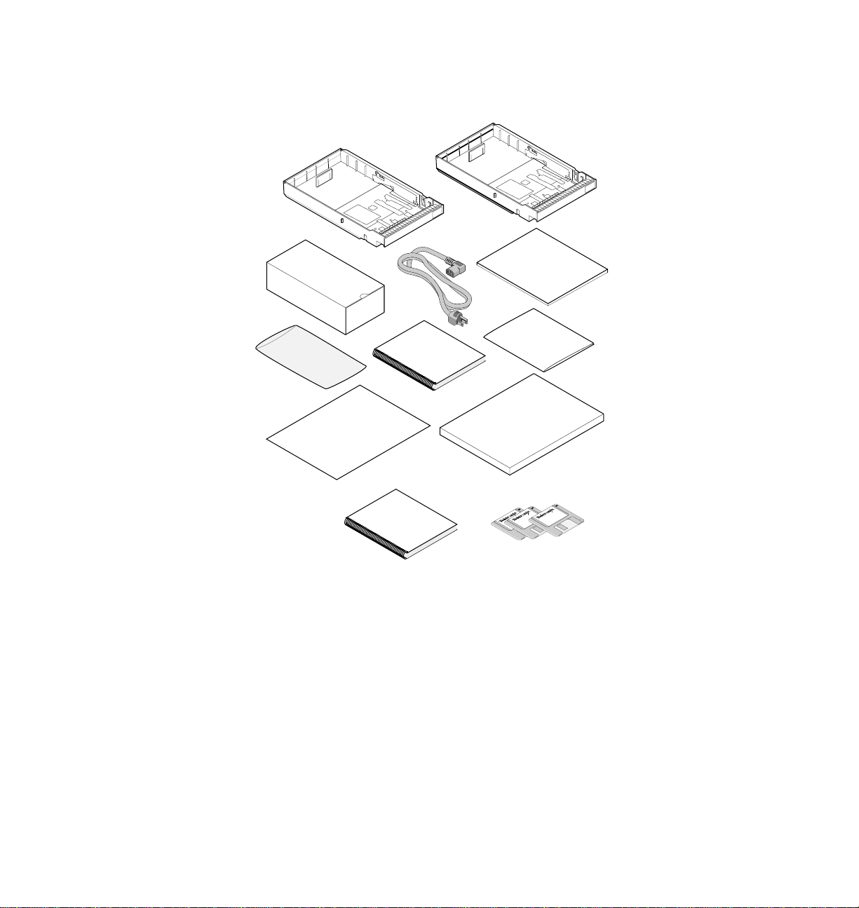
Setting up the printer
What you get with your printer
Paper tray(s)
Sample transfer roll
Power cord
TekColor Care envelope (includes the registration card)
Cleaning kit
Phaser 240 Color Printer User Manual
Supplies information sheet
1.
2.
3.
4.
5.
6.
7.
8.
9.
Transparencies
Thermal-transfer paper
Phaser 240 Drivers and Utilities Printing Reference
10.
11.
Tektronix Phaser 240 drivers and utilities diskettes
2-2
Phaser 240 Color Printer
Page 15
2
5
Kit
1
Transfer
Roll
Cleaning
8
Transparency
Sample
6
3
User
Manual
7
9
Paper
Sample
4
TekColor Care
Supplies
Getting Set Up
2
10
Reference
Manual
11
User Manual
9238-01
2-3
Page 16
Getting Set Up
2
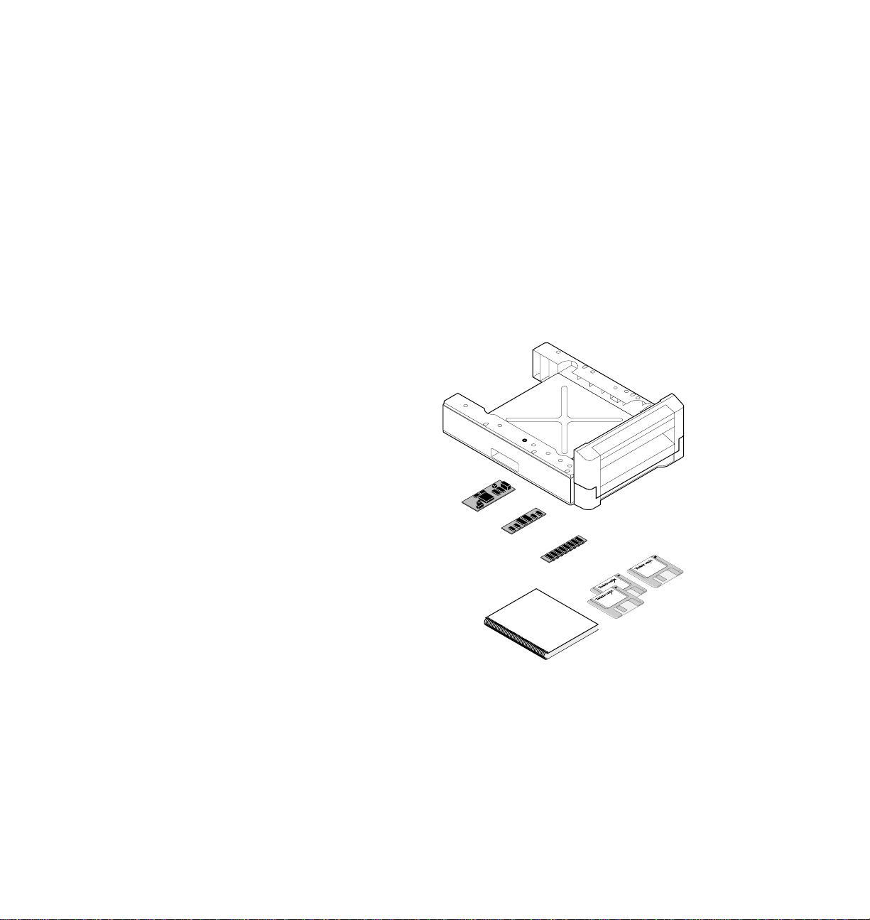
Printer options
1.
2.
3.
4.
5.
Lower Tray Assembly
Ethernet SIMM
Font SIMM (adds 22 fonts for a total of 39 fonts)
Memory (add a single 4-, 8-, or 16-Mbyte SIMM)
Network Utilities for Phaser Color Printers manual and diskettes
1
2-4
Phaser 240 Color Printer
2
3
4
5
Network
Manual
9238-02
Page 17

Installing the optional Lower Tray Assembly
An optional Lower Tray Assembly is available for the Phaser 240 printer
(Tektronix order number 4681FTA). With the optional Lower Tray Assembly
installed, you can configure the printer to be dual-media capable. For
example, you might want to load paper in one tray and transparency in the
other.
Note
Warning
The printer weighs about 18 kg (40 lbs.). Observe standard
precautions for lifting heavy objects.
The printer is not permanently attached to the Lower Tray
Assembly. Take care to move the printer and Lower Tray
Assembly together by using the slots on the sides of the Lower
Tray Assembly. Moving the printer incorrectly may damage it
and may cause personal injury.
Getting Set Up
2
User Manual
2-5
Page 18

Getting Set Up
2
1.
2.
3.
If you have a Lower Tray Assembly, install it by performing these steps:
Place the printer on top of the Lower Tray Assembly.
Make sure that the left and right alignment pins fit in the holes in
the base of the printer.
Plug the Lower Tray Assembly cable into the printer.
To move the printer, use the slots on either side of the Lower Tray
Assembly. Observe standard precautions for lifting heavy objects.
To move the printer more than a few feet, it is easier to disconnect
the Lower Tray Assembly and move it separately from the printer.
1
SECOND
TEST
FEEDER
SWITCH
...
..
...
.
4.
2-6
Note
Phaser 240 Color Printer
3
2
4
1
9238-03
When using the printer with the optional Lower Tray Assembly
installed, make sure that the door covering the upper slot is
closed. You cannot print from the lower tray with the door open.
Page 19
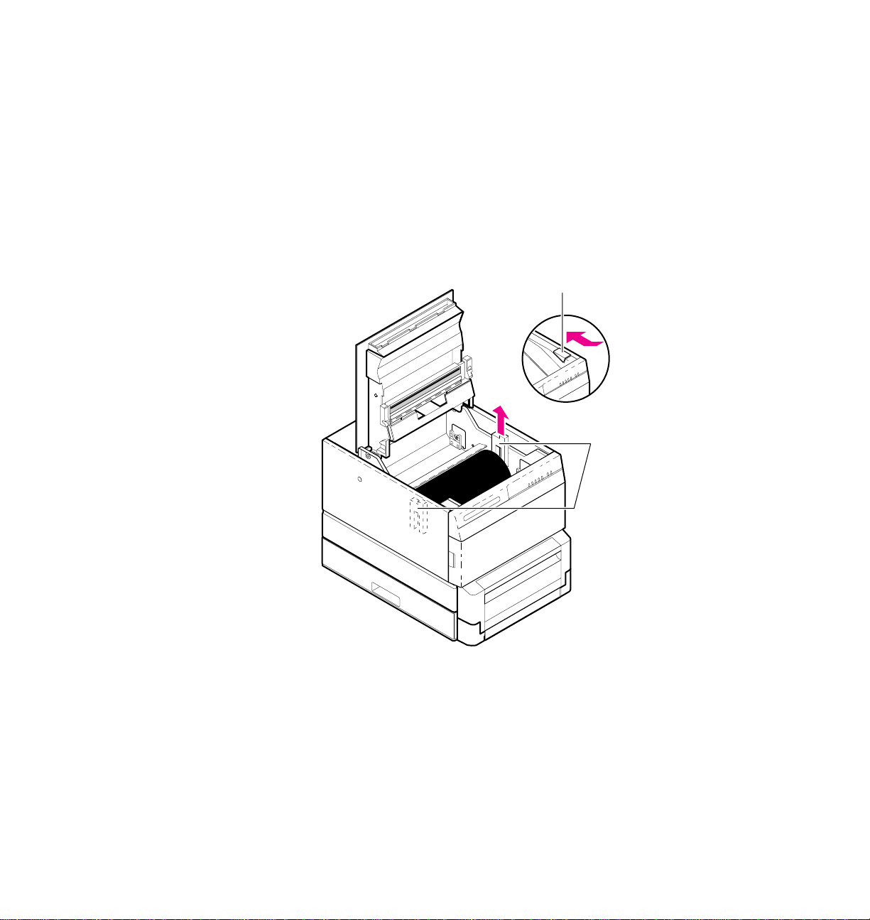
1.
2.
3.
Removing the packing material from inside the printer
Remove the packing tape from the top and front covers.
Press the button; open the top cover.
Remove the shipping material from the sides of the drum. (Keep
all shipping material for storing or shipping the printer).
2
Getting Set Up
3
2
9238-04
User Manual
2-7
Page 20
Getting Set Up
2
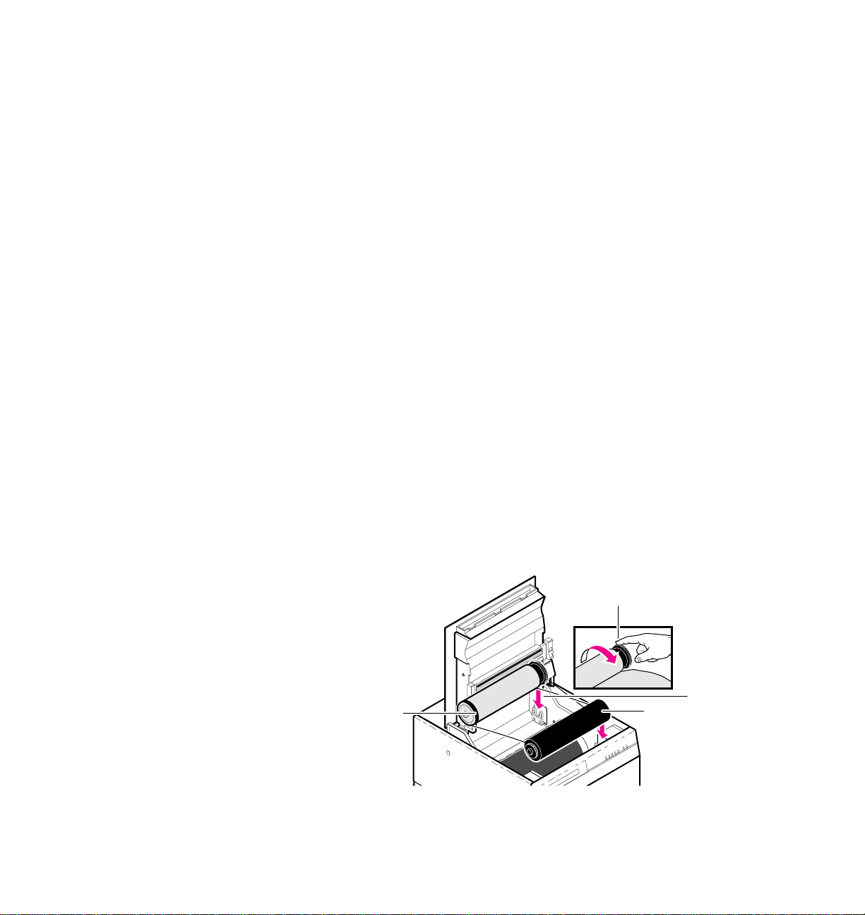
Install the transfer roll
Note
With the top cover still open, install the transfer roll:
1.
2.
3.
4.
5.
6.
ColorCoat™ transfer rolls are used with common laser paper and
perforated premium laser paper; Black and 3-Color transfer rolls
are used with Tektronix transparencies and thermal-transfer
paper.
Remove the transfer roll from the box. Remove the shipping foam
from the transfer roll. Remove the foam clip from the full end of
the roll.
Hold the transfer roll so that the black band on the roll is on
your left.
With the black band on the r oll to your left, place the empty end of
the roll in the slots at the front of the printer.
Place the full end of the roll in the slots at the back of the printer.
Turn the full end of the roll to remove slack.
Close the cover.
2-8
Phaser 240 Color Printer
5
4
2
3
9238-05
Page 21
Adding paper or transparencies
Unpack the paper tray. Be sure to remove all adhesive tape.
Getting Set Up
2
Note
The printer uses a different paper tray for each paper size (Letter,
Letter-perforated, A4, A4-perforated). The trays are not
adjustable.
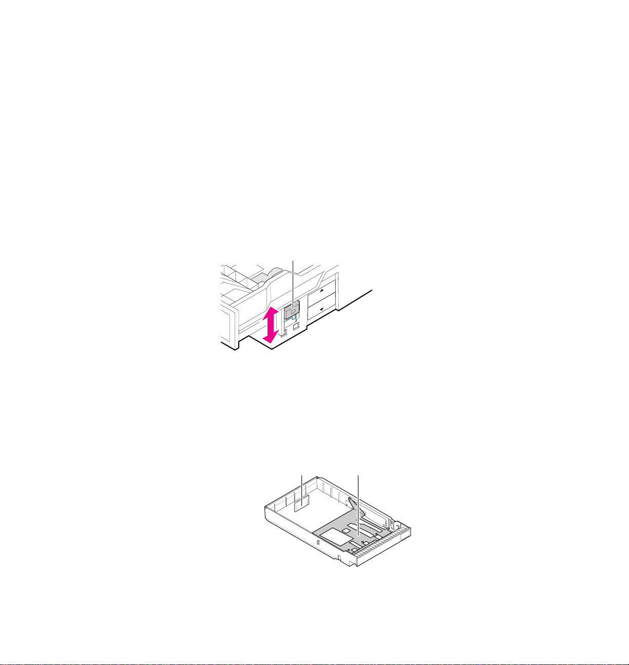
1.
If you are using a tray for perforated paper or transparencies, set
the selection switch on the tray (
1) for paper or transparencies.
Trays for non-perforated plain paper do not have this switch.
1
TRANSPARENCY
PAPER
9238-06
2.
Make sure that the metal plate is all the way down. If necessary,
push the metal plate down until it clicks into place. Do not
attempt to change the position of the vertical tab (3) at the back of
the paper tray.
23
9238-07
User Manual
2-9
Page 22
2
Getting Set Up
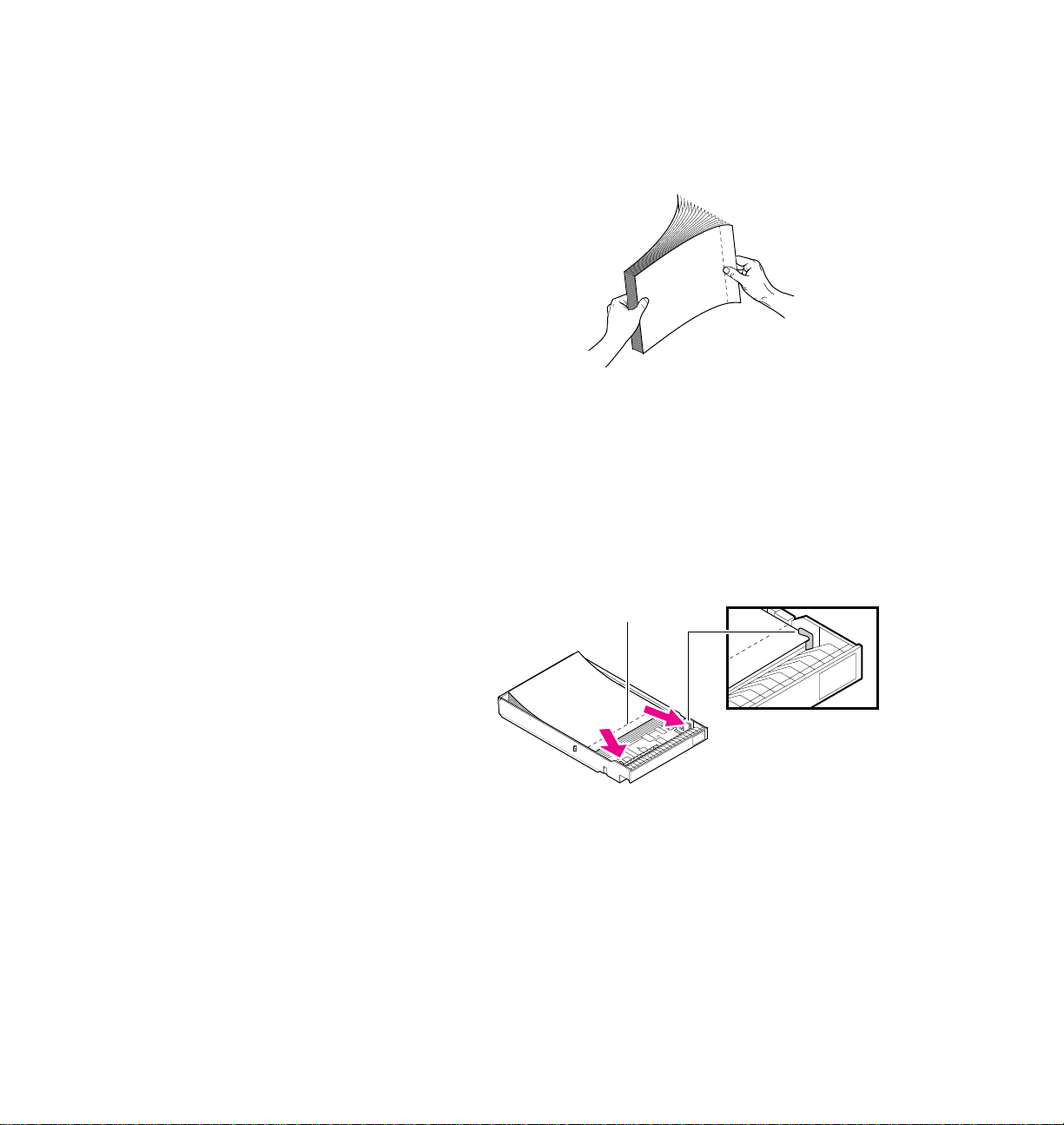
3.
Fan the paper or transparencies.
9238-08
4.
Load perforated paper or transparencies with the perforations
toward the front of the tray.
5.
Place paper or transparencies in the tray under the hooks. Load
transparencies with the film side up. Load thermal-transfer paper
with the shiny side up (not applicable for laser paper).
2-10
Phaser 240 Color Printer
4
5
9238-09
Page 23
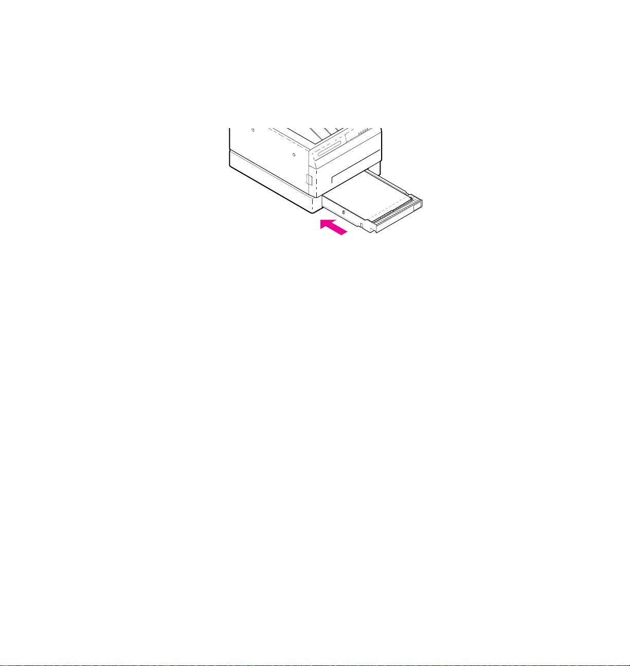
Getting Set Up
If your printer has a single paper tray, push the paper tray into
6.
the slot.
2
6
9238-10
User Manual
2-11
Page 24
2
Getting Set Up
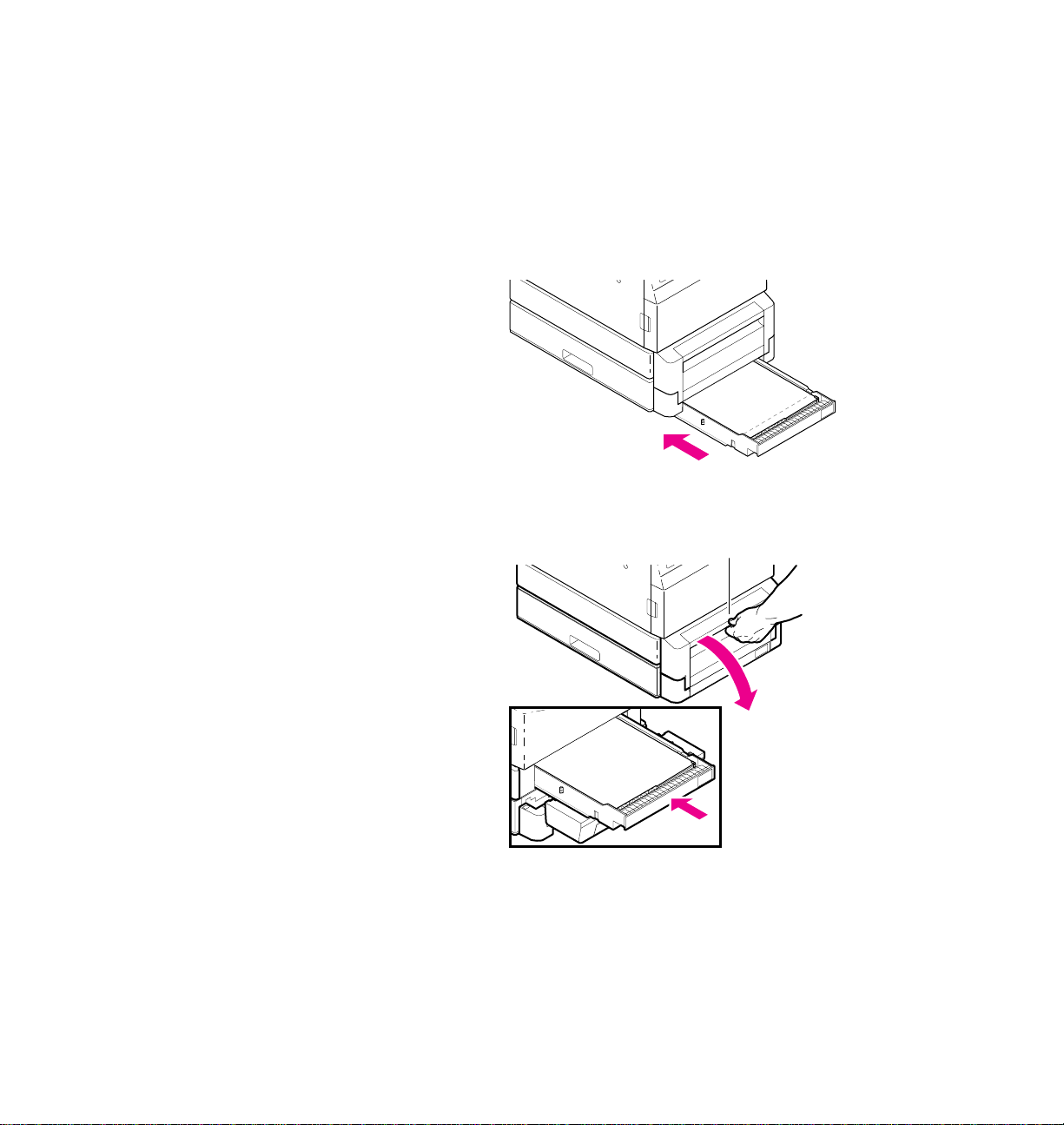
7.
If your printer has a Lower Tray Assembly:
a.
Install a tray in the lower slot.
b.
Open the door to install a tray in the upper slot.
7a
9238-11
7b
9238-12
2-12
Phaser 240 Color Printer
Page 25

Installing options
When you order font, memory, or Ethernet options for the Phaser 240, they
are shipped in separate boxes. These options must be installed in the printer
before you make communication connections and power up the printer.
Follow the instructions included with each option to complete the
installation.
If you ordered the optional 22 fonts for your printer and you are using a
Macintosh computer, you’ll need to also install the screen fonts on the
computer. Refer to the Phaser 240 Drivers and Utilities Printing Reference for
more information.
Getting Set Up
2
User Manual
2-13
Page 26

2
Getting Set Up
Connecting the printer
Printer ports
The Phaser 240 printer is shipped standard with the following data ports:
■ LocalTalk
■ Parallel
The Phaser 240 also has an Ethernet connector located on the rear panel. An
optional Ethernet interface SIMM must be installed to activate the connector .
The optional Ethernet interface provides Ethernet connectivity with
EtherTalk, Novell NetWare, and TCP/IP protocols.
All ports and network protocols are simultaneously active. The printer
accepts print jobs on a first-come, first-served basis.
Note
Always make connection to the printer’s interface ports before
you turn on the printer.
2-14
Phaser 240 Color Printer
Page 27
LocalTalk connection
You can make LocalTalk connections between the printer and a single
computer or on a LocalTalk network using a daisy-chain setup. If your
LocalTalk installation is complex, or if you need assistance, contact your
network system administrator.
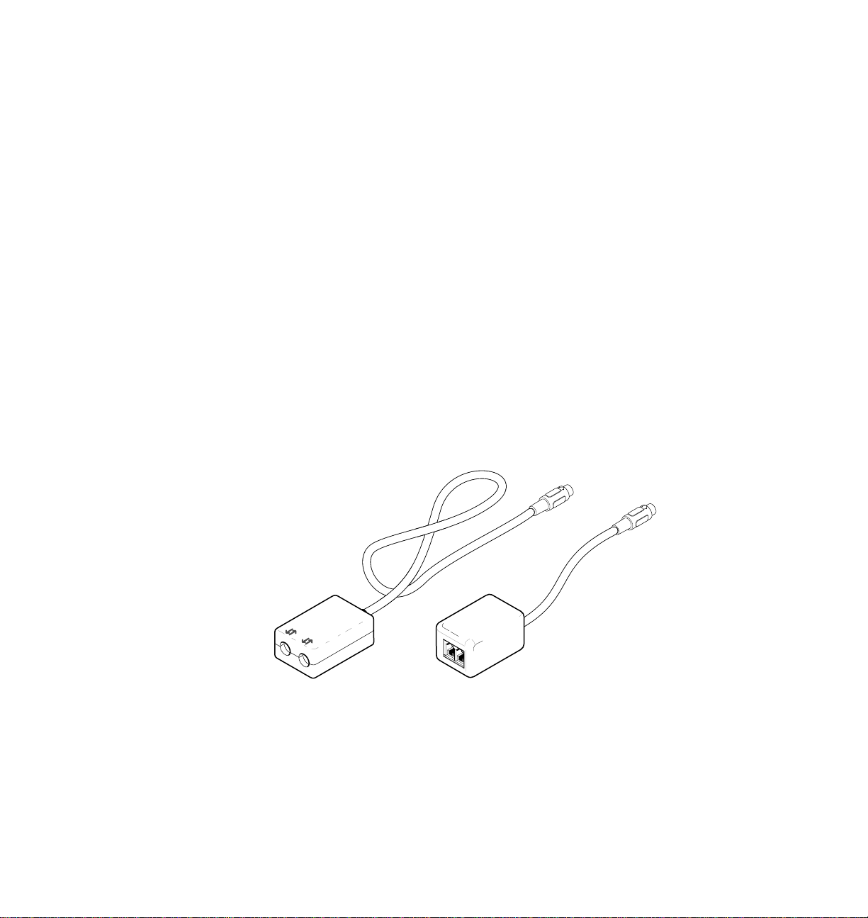
LocalTalk connectors and cables are available through your dealer. This
illustration shows two commonly used types of LocalTalk connectors:
1.
Self-terminating connector
2.
Connector that requires an external terminator, depending on
your network configuration
Getting Set Up
2
Note
Note
Depending on the type of LocalTalk cables you use and your
network configuration, you might need to use terminators at
certain points in the installation. Refer to the documentation for
your LocalTalk connectors and cables for details.
129238-13
LocalTalk is sometimes referred to as AppleTalk. LocalTalk refers
to the physical connection; AppleTalk is the protocol.
User Manual
2-15
Page 28
2
LocalTalk®
Getting Set Up
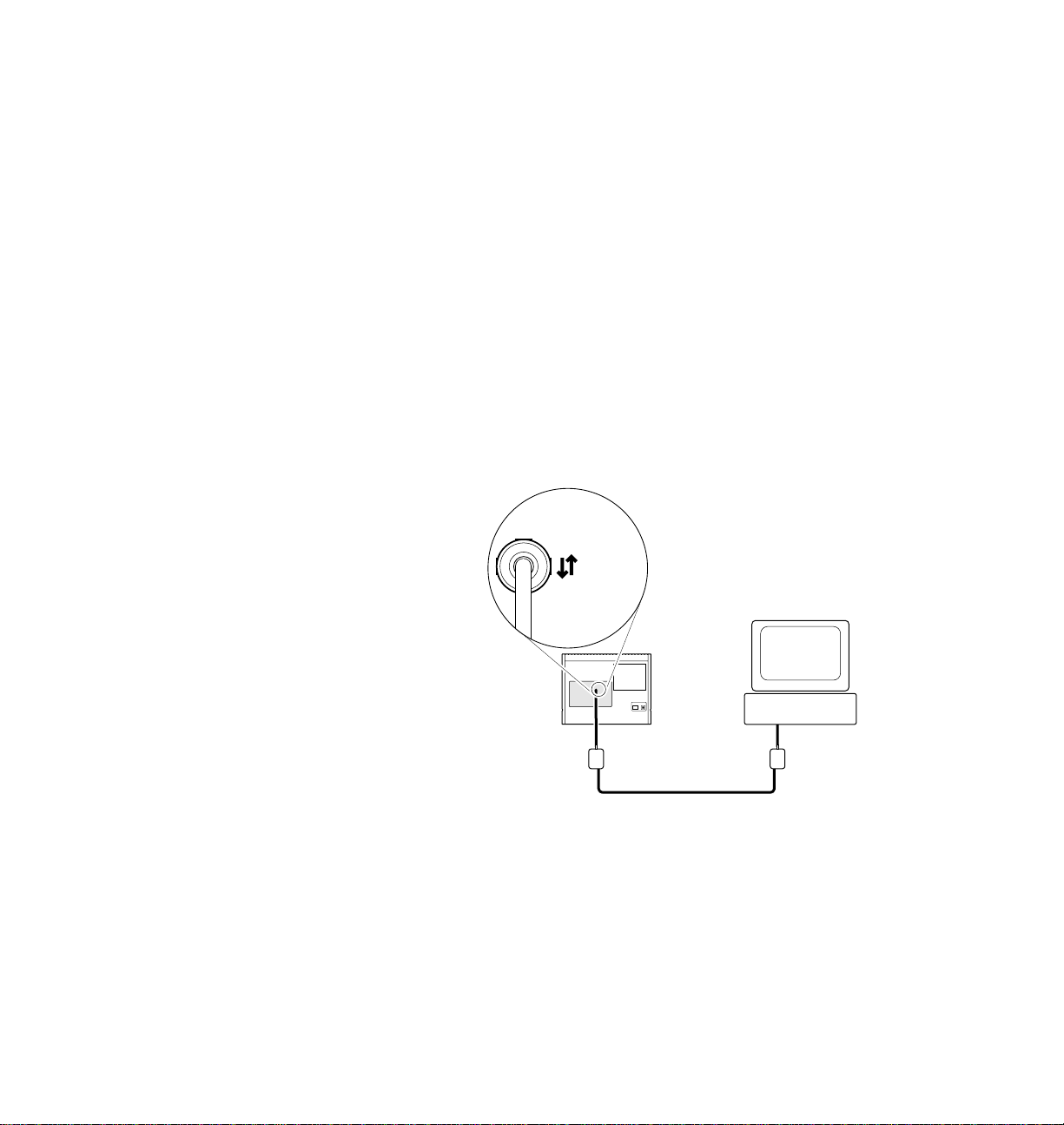
Connecting the printer to a single computer using LocalTalk
You can use LocalTalk connectors and cables to connect the printer directly
to your computer, without connecting it to any other network. Make sure
that the printer is turned off before making any LocalTalk connections.
1.
Connect the short cable of a LocalTalk connector to the printer's
LocalTalk port.
2.
Connect the short cable of another LocalTalk connector to your
computer's LocalTalk port.
3.
Connect a LocalTalk cable from the LocalTalk connector that you
have just attached to your computer to the printer's LocalTalk
connector.
2-16
For details on how to select the printer in the Chooser, change the printer’s
name, or set the printer’s zone, refer to the manual Phaser 240 Drivers and
Utilities Printing Reference. If you have no other connections to make, turn
immediately to “Connecting the power and turning on the printer” on
page 2-19.
Phaser 240 Color Printer
1
3
2
9238-14
Page 29
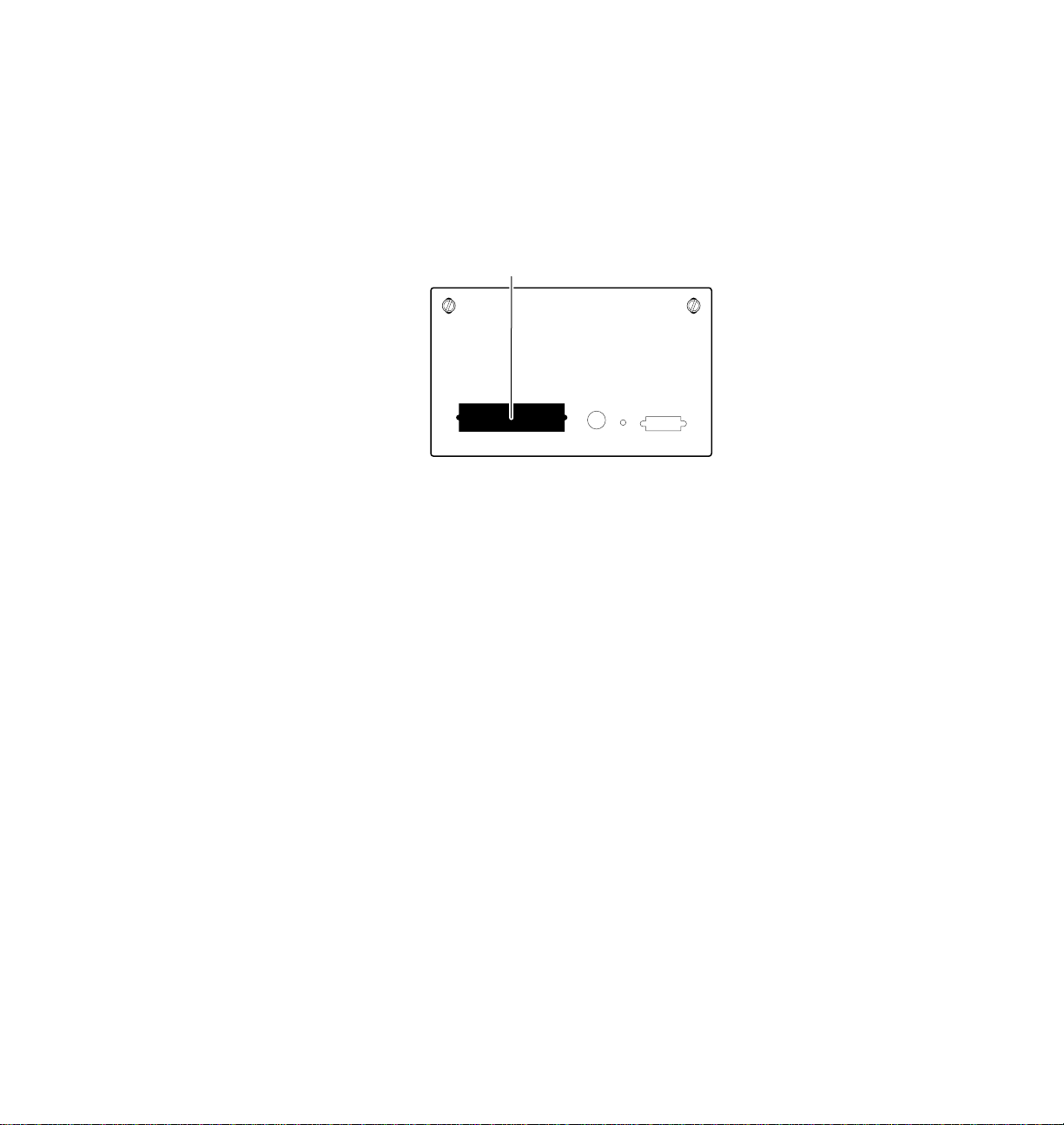
Parallel connection
1.
2.
Getting Set Up
Connect a parallel interface cable to your computer and to the
printer's parallel port.
1
9238-15
If you have no other connections to make, turn immediately to
“Connecting the power and turning on the printer” on page 2-19.
After you turn on the printer and install a driver on your
computer, you may disable timeouts on your computer's parallel
port (see “Setting up PC ports (DOS)” on page 2-34).
2
User Manual
2-17
Page 30
2
Getting Set Up
Ethernet connection
Ethernet is a communication standard that supports very high speed data
transmission. Ethernet capability is provided by an optional Ethernet SIMM
that you must install before powering up the printer. For information on
installing the Ethernet SIMM, refer to the documentation that accompanies
the Ethernet option.
1.
Connect an Ethernet interface cable to the printer's Ethernet port.
1
2-18
Note
Phaser 240 Color Printer
9238-16
For complete information on installing the Phaser 240 printer on
Ethernet networks, refer to the Network Utilities for Phaser Color
Printers manual.
Page 31

Connecting the power and turning on the printer
After you have connected all the interface cables, you are ready to connect
the power cord and turn on the printer.
Getting Set Up
2
Caution
To avoid damaging the printer, make sure that the voltage
select switch is set to match the AC line voltage for your
location and that the power switch is in the off position before
connecting the power cord.
If you move the printer to a location that uses a line voltage other than the
printer’s curr ent setting, refer to “Changing the line voltage” on page C-1 for
information on changing the line voltage selection switch.
1.
Plug the power cord into the printer and into a grounded outlet.
2.
Turn on the printer.
POWER
OFF ON
1
1
2
9238-17
User Manual
2-19
Page 32

2
Getting Set Up
When you turn on the printer, it executes a series of self-tests to determine if
there are any problems. After running self-tests, the printer prints a startup
page, if the startup page is enabled (factory default). After running self-tests
and printing the startup page, the printer is ready for operation. The entire
power-up sequence can last from 1 to 3 minutes, depending on the type of
transfer roll installed and whether the startup page is enabled. The next few
topics describe the printer's power-up sequence in detail.
Front panel at power-up
All indicators light briefly and immediately go out, except POWER and
READY, which remain on for about 10 seconds. Then the READY indicator
blinks while the POWER indicator remains on and the self-tests are run.
When both POWER and READY are on steady (not blinking), the self-tests
are complete.
ERROR JAM RIBBON COVER
MEDIA
READY
POWER
9238-18
When a standard transfer roll is more than 75 percent used up, the front-panel
RIBBON indicator lights, reminding you that it is time to order a new
transfer roll.
When you install the sample transfer roll supplied with the printer, the
RIBBON indicator may light as soon as you install it, or after you make a
few prints. This is because the sample transfer roll contains a limited number
of prints.
For complete information on the front-panel indicator lights, refer to “Front
panel” on page 7-1.
2-20
Phaser 240 Color Printer
Page 33

Getting Set Up
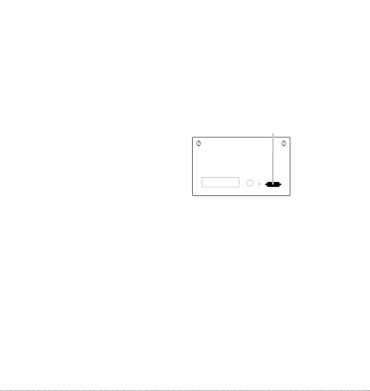
Rear panel at power-up
During the first 40 - 60 seconds of the power-up sequence, the rear-panel
status indicator (
the status indicator blinks continuously, indicating that the printer is ready
for normal operation.
A) goes on and off periodically. After about 40 - 60 seconds,
A
9238-19
2
User Manual
2-21
Page 34

2
Getting Set Up
Startup page
The startup page contains information on printer configuration and error
messages. The printer produces a startup page when you turn on the printer
and self-tests run successfully, if the startup page is enabled (default setting).
The printer takes from 60 to 90 seconds to print the startup page, depending
on the type of transfer roll installed. The READY indicator blinks while the
startup page is printing.
The startup page can be enabled and disabled by sending a utility file to the
printer from the printer’s utilities diskettes. For information, refer to the
Phaser 240 Drivers and Utilities Printing Reference.
Note
After the startup page prints, a registration page prints if the
printer has made between six and eight prints since it was built.
If you have not already registered your printer, please do so by
filling out this page and sending it in.
When the printer is ready for operation
When the power-up sequence is complete, both the POWER and READY
indicators remain on, indicating that the printer is ready for operation.
2-22
Phaser 240 Color Printer
Page 35

Installing a driver on your computer
Phaser 240 drivers and utilities diskettes
Packaged with your printer are the Phaser 240 drivers and utilities diskettes
for PC and Macintosh. The drivers and utilities let you select between
printer media trays, print quality modes, color correction modes and other
features.
For complete details on the contents of the Phaser 240 drivers and utilities
diskettes and how to use them, refer to the manual Phaser 240 Drivers and
Utilities Printing Reference, which is shipped with the diskettes.
Getting Set Up
2
User Manual
2-23
Page 36

2
Getting Set Up
PC users
Microsoft Windows
The Phaser 240 diskettes include a Tektronix driver for Windows 3.1 for this
printer . If you want to use Microsoft Windows applications with this printer,
install the driver onto your PC.
The Phaser 240 Drivers and Utilities Printing Reference provides a more
detailed driver installation procedure as well as complete information on
using the Tektronix driver with the printer.
To install the Tektronix Windows 3.1 driver:
1.
Start Windows on your PC.
2.
Insert the Tektronix Windows 3.1 Driver and Printer Utilities
diskette into your computer’s disk drive.
3.
In the main window, double-click on the Control Panel.
2-24
4.
Double-click the Printers icon; the Printers dialog box appears.
a.
b.
c.
5.
Type in the name of the disk drive that the PC diskette is in (for
example, drive B) and click
6.
To install your printer, do the following:
a.
Phaser 240 Color Printer
Click the Add button.
In the List of Printers, select Install Unlisted or Updated
Printer.
Click the Install button.
OK.
Print a startup page to determine the printer’s configuration.
If there are 17 resident fonts, you have the standard font
configuration. If you have 39 fonts, your printer has the font
upgrade. Refer to “Startup page” on page 2-22 for instructions
on printing a startup page.
Page 37

Getting Set Up
If you have the standard 17 fonts, select
b.
Tek Phaser 240 (TekColor) 17.
If you have the optional font upgrade (T ektr onix order number
4681F1F) with 22 additional fonts (a total of 39 fonts), select
Tek Phaser 240 (TekColor) 39.
2
Note
Note
7.
If the printer has the font upgrade, you must install the
Tek Phaser 240 (TekColor) 39 driver for Windows to recognize
and use all of the printer’s fonts.
If you select Tek Phaser 240 (TekColor) 39 and you only have
the standard 17 printer fonts, any of the additional fonts selected
within an application are printed in the Courier font.
c.
Click OK. The driver software you need is automatically
installed.
The printer’s configuration page contains the information you
need to set up the printer port. For information on printing a
configuration page, see “Printing the configuration page” on
page 6-13.
Assign the printer to a port:
a.
Select the printer from the list of Installed Printers.
b.
Click Set As Default Printer if you want this printer to be the
default.
c.
Click Connect to display the Connect dialog box.
d.
In the Connect dialog box, set the Transmission Retry value to
850. Refer to your Windows documentation for details.
User Manual
2-25
Page 38

2
Getting Set Up
e.
In the Connect dialog box, select a port:
Interface
Parallel LPT1 or LPT2
Network Network button
If you selected a parallel port, go on to Step f.
If you clicked on the Network button, the Printers – Network
Connections dialog box appears. Fill in each item according
to the printer’s configuration page. Refer to your Windows
documentation for details or ask your network administrator
for help.
f.
Click OK in the Connect dialog box and close the Printers
dialog box.
Select
2-26
Phaser 240 Color Printer
Page 39

Getting Set Up
DOS
Check the list of supported printers in your DOS application for support of
the Phaser 240 printer. If the list does not include this printer, check to see if
other Tektronix Phaser series printers are listed and choose one of those.
Otherwise, use a generic color PostScript driver. Refer to the Phaser 240
Drivers and Utilities Printing Reference for more information.
2
Note
Generic PostScript printer drivers do not have information about
this particular printer , for example, its page sizes or its image area
size. Using a standard Letter- or A4-size media selection should
produce acceptable results.
User Manual
2-27
Page 40

2
Getting Set Up
Macintosh users
Install the Phaser 240 driver onto your Macintosh to make the best use of the
printer. Phaser 240 driver allows you to select Tektronix Phaser page sizes,
upper and lower paper trays, and T ekColor color corr ections for a Phaser 240
printer .
■ Use the Phaser 240 driver if you are using System Software 6.0.7,
or 7.0 and later. The Phaser 240 driver is a Tektronix-modified
version of Apple’s LaserWriter 7.1.2 printer driver. If you are
using System Software 7.5 with QuickDraw GX, you must disable
QuickDraw GX before using this driver; the Phaser 240 driver
does not work with QuickDraw GX.
■ Use the Phaser 240 GX driver if you are using QuickDraw GX and
System Software 7.5. The Phaser 240 GX driver works with
QuickDraw GX applications and with non-QuickDraw GX
applications.
The Phaser 240 Drivers and Utilities Printing Reference pr ovides detailed driver
installation procedures and complete information on using the Tektronix
drivers with your printer.
2-28
In addition to installing a driver, you may also need to install PPDs
(PostScript printer description files) for applications such as Aldus
PageMaker and QuarkXPress. For details on printing from an application,
refer to the Phaser 240 Drivers and Utilities Printing Reference.
Phaser 240 Color Printer
Page 41

Getting Set Up
Installing the Phaser 240 driver
1.
Make sure that your Macintosh is turned on with System Software
version 6.0.7, 7.0 or later installed.
2.
Insert the Macintosh Driver and Printer Utilities diskette into the
disk drive. When the diskette appears on the desktop, it should be
open, showing the icons inside.
3.
Drag the Phaser 240 driver icon from the diskette to the closed
System Folder icon on your Macintosh hard disk.
■ System 7.0 and later users: at the alert message, click OK to
automatically install the driver in the Extensions folder.
■ System 6.0.7 users: the driver is installed in the System Folder.
4.
System 6.0.7 users: LaserWriter 7.1.2 software is required to use
the Tektronix driver with system 6.0.7. If you need this software,
do the following steps:
2
a.
Open the Old System Items folder on the Macintosh Driver and
Printer Utilities diskette.
b.
Drag the Backgrounder V1.3 and PrintMonitor V7.0 from the
diskette to the closed System Folder icon on your Macintosh
hard disk. At the alert message, click OK to automatically
install these items in their proper places.
c.
Restart your Macintosh to activate the software.
5.
Select Chooser from the Apple menu.
User Manual
2-29
Page 42

2
Getting Set Up
6.
Click the Phaser 240 printer driver icon on the left side of the
Chooser. A list appears with the printers you have connected to
your Macintosh or printers that are available on a network. (If the
printer driver icon does not appear, Restart your Macintosh, and
repeat the printer driver installation procedure; also check the
cable connections on your computer and printer.)
7.
Click on your Phaser 240 printer in the list of printers on the right
side of the Chooser.
8.
Close the Chooser by clicking its close box.
9.
Store the printer diskette in a safe place.
2-30
Phaser 240 Color Printer
Page 43

Getting Set Up
Installing the Phaser 240 GX driver
1.
Make sure that your Macintosh is turned on with QuickDraw GX
and System Software version 7.5 installed.
2.
Insert the Macintosh Driver and Printer Utilities diskette into the
disk drive.
3.
When the diskette appears on the desktop, it should be open,
showing the icons inside.
4.
Drag the Phaser 240 GX driver icon from the diskette to the closed
System Folder icon on your Macintosh hard disk. At the alert
message, click OK to automatically install the driver in the
Extensions folder.
5.
Select Chooser from the Apple menu.
6.
Click the Phaser 240 GX printer driver icon on the left side of the
Chooser. A list appears with the printers you have connected to
your Macintosh or printers that are available on a network. (If the
printer driver icon does not appear, Restart your Macintosh, and
repeat the printer driver installation procedure; also check the
cable connections on your computer and printer.)
2
7.
In the Connect via field’s pop-up menu, select your printer’s
communication method:
■ The AppleTalk option is the standard network connection.
■ The Servers option is used to select a shared desktop printer. See
the Phaser 240 Drivers and Utilities Printing Reference for details.
User Manual
2-31
Page 44

2
Getting Set Up
8.
Click on your Phaser 240 in the list of printers on the right side of
the Chooser.
9.
Click the Create button to create a desktop printer. An icon of the
printer appears on the desktop with the same name as the printer
selected in the Chooser.
10.
Close the Chooser by clicking its close box.
11.
Store the printer diskette in a safe place.
2-32
Phaser 240 Color Printer
Page 45

Workstation users
Getting Set Up
The printer-control PostScript files that are on the Windows 3.1 Driver and
Printer Utilities diskette (PC format) can be used with Unix and VMS
workstations. These files let you set up your spooling system to select
between media trays, print quality modes, color correction modes and other
features. Unix workstation users can access utility files in the following
ways:
■ Mount the PC diskette on your workstation.
■ Download utility files from the Tektronix Bulletin Board
Service (BBS).
■ Request utility files from the Tektronix Color Printer Information
Server over the Internet.
Most workstations with 3.5-inch disk drives provide a device driver that
allows you to mount a PC floppy diskette. Refer to the Phaser 240 Drivers and
Utilities Printing Reference for information about mounting PC diskettes.
2
Refer to Chapter 6, “Troubleshooting,” for information about accessing
Tektronix’ Bulletin Board Service or Color Printer Information Server.
User Manual
2-33
Page 46

2
Getting Set Up
Setting up PC ports (DOS)
Parallel port setup
If you are using the printer's parallel port, you should disable timeouts on
your computer's parallel port. Disabling timeouts ensures that large files
will print, even if data transmission is slow.
The DOS MODE command is used to disable timeouts on your computer's
parallel port. Type this command at the DOS prompt (if LPT1 is not
available, use LPT2):
MODE LPT1:,,P
See your DOS documentation for details on the MODE command.
You may want to add the MODE command to your AUTOEXEC.BAT file, so
that it takes effect every time you turn on your computer.
2-34
Phaser 240 Color Printer
Page 47

Turning on and off the startup page
You can enable and disable the startup page by sending utility files from the
printer’s utilities diskette to the printer. For details on controlling the
startup page, refer to the Phaser 240 Drivers and Utilities Printing Reference.
Even when the startup page is enabled, you can still keep it from printing by
removing the paper tray(s) at power-up. Put the paper tray(s) back in after
the READY light stops blinking.
What next?
■ Once you have set up all the hardware and connectors, installed
any options, installed the software on your computer, and turned
on the power, you are ready to print. Chapter 3, “Printing,”
contains useful information on printing features such as color
corrections, fonts, and printing hints. For detailed information on
printing options, refer to Phaser 240 Drivers and Utilities Printing
Reference.
Getting Set Up
2
User Manual
2-35
Page 48

2
Getting Set Up
2-36
Phaser 240 Color Printer
Page 49

Chapter
3
Printing
Which computer?
You can print to your printer from any of the following computers,
providing the printer has the appropriate interface port. Refer to “Printer
ports” on page 2-14 for more information.
■ PC — in Windows and in DOS
■ Macintosh
■ Unix and VMS Workstations
To print from a PC running Windows or from a Macintosh, you should have
first installed a T ektr onix driver for your computer. Tektr onix printer drivers
contain page size information and selections specifically for the type of
media or tray being used with your printer. For information on installing
the drivers, see “Installing a driver on your computer” on page 2-23. For
detailed information on the drivers, refer to the Phaser 240 Drivers and
Utilities Printing Reference. If you are printing from a PC running DOS, you
must first set up the driver in your application software.
Use the following instructions to set up printing from your computer.
User Manual
3-1
Page 50

3
Printing
Printing from a PC (Windows)
1.
Make sure that the Tektronix driver for Windows has been
installed.
2.
From the File menu, select the Print Setup command or the
similar command in your application. Select the Tek Phaser 240
(TekColor) driver (the 17-font or 39-font version according to the
installation you performed under “Microsoft Windows” on
page 2-24) and select Setup. If you have previously set the printer
as the default printer, it will already be selected on the list.
3.
Use the Setup dialog box to select the paper size, paper source
(Upper tray, Lower tray, or Auto Select), and other printing
options.
4.
Click on the Options button to display the Options dialog box.
a.
Click on the Printer Features button to display the Tektronix
Printer Features dialog box.
3-2
b.
For details on the Tektronix driver, refer to the Phaser 240 Drivers and Utilities
Printing Reference.
Phaser 240 Color Printer
Use the Tektronix Printer Features dialog box to select
TekColor color corrections and print quality.
If the Printer Features button does not appear in the Options
dialog box, the Tektronix Windows driver probably is not
installed or the printer has not been selected.
Page 51

Printing from a PC (DOS)
1.
In your application software, set up the printing options for a
color printer driver. For more information on making these
selections, refer to your application software’s user manual.
2.
Make sure that the PC communication ports have been set up
correctly. Refer to “Setting up PC ports (DOS)” on page 2-34 for
instructions.
3.
Select the printer driver for the Phaser 240, a Tektronix Phaser
printer, or a generic color PostScript driver.
Printing
3
Note
4.
Generic PostScript printer drivers do not have information about
your Phaser 240 printer, for example, its page sizes and its image
area size. Using a standard Letter- or A4-size media selection
should produce acceptable results.
a.
Select the appropriate port (an LPT port for parallel or one of
the network connections).
b.
Set the page margins in your application software as needed.
For details on the printer's paper and margin sizes, refer to
“Margins and print area” on page 3-9.
Execute the application software's print command. Refer to the
application software's user manual for details.
User Manual
3-3
Page 52

3
Printing
Printing from a Macintosh
The Macintosh Driver and Printer Utilities diskette includes two Macintosh
printer drivers that allow you to select printer features.
Using the Phaser 240 driver
1.
Install the Tektronix printer driver for the Macintosh if needed.
Refer to “Macintosh users” on page 2-28 for instructions.
2.
Select the driver in the Chooser.
3.
To print a file, use the Page Setup and Print commands from the
File menu within your application:
a.
In the Page Setup dialog box, select the desired paper size
from the pop-up menu so that the application uses the correct
margins for the printer. To see the choices, use the pop-up
menu to the right of the standard Paper sizes.
3-4
b.
Phaser 240 Color Printer
In the Print dialog box, click the TekColor button to open the
TekColor Options dialog box, in which you can select the
TekColor color corrections, print quality, and paper trays. For
more details on the driver, refer to the Phaser 240 Drivers and
Utilities Printing Reference.
Page 53

Using the Phaser 240 GX driver
1.
Install the Tektronix printer driver for the Macintosh if needed.
Refer to “Macintosh users” on page 2-28 for instructions.
2.
Select a desktop printer.
3.
Print from the driver using one of the following methods:
■
For QuickDraw GX applications
Select the desktop printer you want to use, then use the Print dialog
box (select Print from the File menu).
■
For non-QuickDraw GX applications
You can print to the default desktop printer from the Print dialog
box (select Print from the File menu). To change the default
desktop printer, select (highlight) the desktop printer you want to
use, then select Set Default Printer from the Printing menu.
Refer to the Phaser 240 Drivers and Utilities Printing Reference for more
information on using the Phaser 240 GX printer driver.
Printing
3
User Manual
3-5
Page 54

3
Printing
Printing from a Unix or VMS workstation
You can print from a workstation through Ethernet or parallel interfaces.
Workstation users can print from any application that generates color
PostScript.
For Unix and VMS environments, Tektronix offers Phaser Print. Phaser Print
provides fast raster file and screen copy printing to Tektronix color printers.
Phaser Print also provides a graphical user interface for push-button control
of Tektronix printer features.
Phaser Print software is available for these workstations:
Workstation Operating System
Sun Sun OS 4.1.X, Solaris 2.X
SGI IRIX 4.0.5 and 5.2
HP 9000 700/800 HPUX 9.X
IBM RS/6000 AIX 3.2
DECstation Ultrix 4.X
DEC Alpha OSF/1 1.3
3-6
Note
Phaser Print works with the workstation’s native spooling system to print
PostScript files and raster files in these formats: Sun Raster Format (SRF),
xwd, and SGI RGB.
If you ordered the TCP/IP Ethernet option for your printer, you received a
demonstration copy of Phaser Print on a compact disk (CD). If you did not
receive a demonstration CD but would like one, or if you would like to
purchase a licensed version of Phaser Print, contact your dealer, local
Tektronix office, or in the United States, call 1-800-835-6100.
Phaser 240 Color Printer
Tektronix offers a similar solution for DEC OpenVMS VAX and
DEC OpenVMS AXP.
Page 55

Printing
For VMS environments, Tektronix also offers PhaserSym, a VMS print
symbiont. Refer to Appendix B for ordering information.
For information on printing from workstations and setting up spooling
systems, you can contact HAL, the Tektronix automated fax system by
calling direct (503) 682-7450 or, in the United States or Canada, by calling
toll-free 1-800-835-6100. Refer to “Using the automated fax systems” on
page 6-16 for details on using the HAL system.
For workstation users who prefer not to use Phaser Print, the printer-contr ol
PostScript files that are on the Windows 3.1 Driver and Printer Utilities
diskette (PC format) can be used for Unix workstations. These files let you
set up your spooling system to select between media trays, print quality
modes, color correction modes and other features. Most workstations with
3.5-inch disk drives provide a device driver that allows you to mount a PC
floppy diskette.
If you don’t have the means of transferring utility files to control printer
features from the PC diskette, you can download utilities and files from the
Tektronix Bulletin Board Service (BBS) or request files from the Tektronix
Color Printer Information Server, an automatic file serving program on the
Internet. Refer to “Whom to call for help” on page 6-14 for information
about accessing Tektronix’ Bulletin Board Service or Color Printer
Information Server.
3
User Manual
3-7
Page 56

3
Printing
Printing from specific applications
Refer to the Phaser 240 Drivers and Utilities Printing Reference for information
on PostScript printer description files required by some applications.
In addition, you can get tips on printing from certain applications
(such as QuarkXPress and PageMaker) by contacting HAL or EuroHAL, the
Tektronix automated information systems. HAL and EuroHAL fax you
information immediately on applications and other topics. T o receive a HAL
FAX catalog, call toll-free in the U.S. 1-800-835-6100 or dial direct,
(503) 682-7450. For a EuroHAL catalog, use the telephone numbers
provided in “Whom to call for help” on page 6-14. For more information on
HAL and EuroHAL, see “Using the automated fax systems” on page 6-16.
3-8
Phaser 240 Color Printer
Page 57

Margins and print area
When the printer places an image on paper, the image is a bit smaller than
the paper size. You may need to adjust the page margins in your application
software to match the print area.
Perforated paper and transparencies
Use Tektronix perforated paper or transparencies and the Tektronix
Phaser 240 driver to get the largest image areas. With Tektronix perforated
paper or transparencies, you can print the largest area and tear of f the excess
at the perforation. This gives full A or A-4 Letter-size images within ISO
margins.
This illustration shows the largest image areas for perforated paper and
transparencies. All margins are 5 mm (0.2 in.). The bottom margin is
5 mm (0.2 in.) after the perforated area is removed.
1.
American A-size (LETTER PERF)
Printing
3
2.
Metric A4-size (A4 PERF)
1
8.5 x 12.3 in.
8.1 in.
10.6 in.
2
210 x 313 mm
200 mm
287 mm
9238-20
User Manual
3-9
Page 58

3
Printing
Non-perforated plain paper
This illustration shows the largest image areas for non-perforated plain
paper. All margins are 5 mm (0.2 in.), except the bottom margin (21 mm for
A4-size, 0.83 in. for A-size).
Note
The standard trays supplied with the printer are for Tektronix
perforated paper and transparencies; they are not adjustable for
plain paper. Trays for plain paper must be ordered separately.
1.
American A-size (LETTER)
2.
Metric A4-size (A4)
1
8.5 x 11 in.
8.1 in.
10 in.
2
210 x 297 mm
200 mm
271 mm
9238-21
3-10
Phaser 240 Color Printer
Page 59

Using two paper trays
Printing
3
Note
When using a printer with a Lower Tray Assembly, make sure
that the door covering the upper slot is closed before you try to
make a print from the lower tray. You cannot print from the
lower tray with the door open.
Recommended paper tray selections
Use If
Upper or
Lower tray
Auto Select You use the same media in both trays.
You use different media in each tray or different sizes in each tray.
Some examples:
■ Paper in one tray and transparency in the other.
■ Standard paper in one tray and special letterhead in the other.
■ Perforated paper in one tray and non-perforated in the other.
You can select the Upper or Lower tray by using a Tektronix Phaser 240
driver or utility files provided on the printer’s utility diskettes. If you select
the upper or lower tray by one of these methods, the printer will pick paper
from the selected tray until the tray is empty. When the tray is empty,
printing stops until the selected tray is filled.
You can also select Auto Select by using a Tektronix Phaser 240 driver or a
utility file provided on the printer’s utility diskettes. If you select
Auto Select by one of these methods, the printer will pick paper from the
tray that contains the selected paper size. When that tray is empty, the
printer will automatically pick from the other tray if it also contains the
selected media size.
Note
Paper tray selections made in the driver take priority over
selections made by sending utility files to the printer.
In all cases, you can change the printer's tray-switching behavior by sending
the appropriate utility file to the printer. For more information, see the
Phaser 240 Drivers and Utilities Printing Reference.
User Manual
3-11
Page 60

3
Printing
Selecting driver features
You can use the Phaser 240 drivers to select Phaser 240 features:
■ Page sizes
■ Paper trays
■ Color corrections
■ Print quality modes
For complete instructions on installing and using the Phaser 240 drivers, see
the Phaser 240 Drivers and Utilities Printing Reference.
Print modes
You can select between the printer’s print quality modes using a Phaser 240
printer driver or utility files provided on the Phaser 240 drivers and utilities
diskettes. Refer to the Phaser 240 Drivers and Utilities Printing Reference for
complete details.
3-12
■ Standard mode is the default. It provides high-quality
300 x 300 dpi prints with the fastest print time.
■ Enhanced mode provides improved 300 x 300 dpi prints; print
time is increased by 10 seconds over Standard mode.
■ High Resolution mode provides exceptionally high-quality
600 x 300 dpi prints. In High Resolution mode, image processing
time is about 30% longer than with Standard mode. Also, the
printer’s paper-marking speed can be up to twice as long as
Standard mode. (The paper-marking speed is the time it takes the
printer to put the colored wax on the paper after it has processed
the image).
Note
Phaser 240 Color Printer
High Resolution print mode is only available when an 8- or
16- Mbyte memory option is installed.
Page 61

Color corrections
The default color correction for the Phaser 240 is Vivid Color. You can select
between the printer’s other TekColor color correction modes using a
Phaser 240 printer driver or utility files provided on the Phaser 240 drivers
and utilities diskettes. For complete information on color correction, refer to
the Phaser 240 Drivers and Utilities Printing Reference.
If you are using TekColor Dynamic Correction in the Phaser 240 drivers, the
settings you choose in the drivers override any color correction set by DIP
Switches inside the printer’s rear panel door. Refer to Chapter 7, “Front and
Rear Panels,” for more information on DIP Switches.
Printing
3
Note
The print driver help window provides a short description of each
color correction mode. To access information, click on the Help
button (for a Macintosh, in the TekColor Options dialog box;
for Windows, in the Tektronix Printer Features dialog box).
User Manual
3-13
Page 62

3
Printing
Fonts
Resident typefaces (PostScript)
The Phaser 240 supports 17 fonts in its standard configuration. An
additional 22 fonts can be added by installing font upgrade kit 4681F1F.
1.
Printer’s resident typefaces.
2.
Additional 22 resident typefaces available with a font SIMM
provided in upgrade kit 4681F1F.
1 2
3-14
9238-22
Phaser 240 Color Printer
Page 63

Resident typefaces (PCL5)
For monochrome PCL5 (Printer Command Language) printing (HP LaserJet
III emulation), the printer supports Courier , Times, and Univers typefaces in
the following styles and stroke weights: medium, bold, italic medium, and
bold italic.
Downloading fonts
The fonts resident in the printer are stored in the printer as outlines and are
always available for printing. The PostScript interpreter in the printer can
also accept and store additional fonts known as downloadable fonts. If you
want to print PostScript outline fonts that are not built into the printer, you
can transfer or download outline fonts from your computer to the printer.
Downloading fonts saves print time if you plan to print several documents
or a large document using those fonts.
When you download a font, it is stored in the printer’s memory. You can
download as many outline fonts as the printer’s memory allows. Adding
more memory expands the number of fonts that can be downloaded to the
printer.
Printing
3
The printer accepts Type 1 and Type 3 downloadable fonts including those
from Adobe, AGFA, Bitstream, Microsoft, Apple, and many others.
The printer also accepts TrueType downloadable fonts which can be scaled
to any point size. TrueType fonts look the same on the screen as they do
when printed.
You download a font from a PC or Macintosh the same way you download
fonts to any PostScript printer. Follow the documentation that was shipped
with your fonts.
User Manual
3-15
Page 64

3
Printing
Installing Macintosh screen fonts
The Phaser 240 Macintosh diskette includes screen fonts corresponding to
the printer’s fonts. If these screen fonts are not already installed on your
system, you must install them if you want to see the printer’s resident
typefaces on the Macintosh screen. For information on how to install these
screen fonts, see the Phaser 240 Drivers and Utilities Printing Reference.
3-16
Phaser 240 Color Printer
Page 65

Printer languages: PostScript, HP-GL, PCL5
With Adobe IntelliSellect™ technology, Phaser 240 printers automatically
sense the language of the print job and process it accordingly. This is called
automatic language selection. You can also set up any printer port to receive
one language only. If you set up a port to receive a particular language only,
the port will only accept jobs of that type. The printer reports an error if
another language is sent to that port. For more information, see the
Phaser 240 Drivers and Utilities Printing Reference.
The default language setting for all ports is PostScript.
Enabling and disabling automatic language switching
To enable or disable automatic language selection on a port, send the
appropriate utility file to the printer. For more information, see the
Phaser 240 Drivers and Utilities Printing Reference.
Printing
3
User Manual
3-17
Page 66

3
Printing
Printing hints
Getting the largest printed picture
Use the Tektronix Phaser 240 driver and perforated paper or transparencies
to get the largest print areas. You may also have to adjust the margins in
your application software.
Why should I use perforated paper?
By using Tektronix perforated paper (and transparencies), you can
print full A-size or A4-size images with standard ISO margins
(5 mm; 0.2 in.).
How long does it take to make a print?
The total print time depends on the image complexity, the type of port used,
and the printer's paper-marking speed. The paper-marking speed is the
time it takes the printer to put the colored wax on the paper, once it has
received the processed image.
3-18
Of these three elements, only the printer's paper-marking speed is
predictable; the others can vary greatly depending on your system
configuration and the type of image you are printing. However, the
Phaser 240 PostScript interpreter combines very fast image processing and
communication with sophisticated memory management to keep the total
print time to a minimum. For details on the printer's paper-marking speed,
see “Specifications” on page A-3.
Phaser 240 Color Printer
Page 67

Chapter
4
Caring for Your Printer
Overview
To ensure the best print quality and the most reliable printer operation,
follow these two simple guidelines:
■ Use only Tektronix transparencies and transfer rolls. When
printing with a 3-Color or Black transfer roll, use only Tektronix
thermal-transfer paper. When printing with a ColorCoat™
transfer roll on common laser paper, use paper that conforms to
the guidelines given in “Recommended paper types” on page 5-4.
■ Perform the regular cleaning described in this chapter.
Importance of cleaning
By performing regular cleaning, you can ensure that your printer produces
the highest quality prints. Regular cleaning also helps prevent paper jams,
smudged prints, skewed images, and misregistration. If you clean the
printer at intervals listed under the next topic, “When to clean,” you will
experience fewer paper problems, improved print quality, and less
downtime.
Cleaning the printer is easy. Follow the cleaning procedures given in the
next few pages, or use the
cleaning kit.
Cleaning Instructions that come with each
User Manual
4-1
Page 68

4
Caring for Your Printer
When to clean
Every time you replace the transfer roll, clean these printer parts:
■ Thermal head and transfer roll guide
■ Paper-feed rollers
■ Paper-pick rollers
Clean these printer parts every 5,000 prints, or as needed to prevent
smudging on prints:
■ Transfer roll sensor pad
■ Drum
■ Exit rollers
A preventive check by a Tektronix field service representative is
recommended every 10,000 prints or every year. The startup page and the
configuration page report the number of prints made since the printer was
shipped from Tektronix.
4-2
Phaser 240 Color Printer
Page 69

Cleaning kit
Caring for Your Printer
A cleaning kit comes with the printer. The cleaning kit contains these items:
■ Lint-free cleaning wipes
■ A plastic bottle for isopropyl alcohol
■ A cleaning tray for cleaning paper-pick rollers
■ Cleaning instructions (you may use those instructions, or follow
the instructions in the next few pages)
For the cleaning kit that is shipped with the printer, you must supply
isopropyl alcohol (available at pharmacies); shipping regulations prohibit
supplying alcohol or presoaked cleaning materials with the printer.
In general, you should use the purest isopropyl alcohol available to you.
99% pure is best, and 90% also works well.
4
Caution
Note
Do not use rubbing alcohol because it can contain water and
oils that leave undesirable residue on the printer parts.
To order a new cleaning kit, call your dealer or Tektronix (order
number 016-1233-00). You can also order a cleaning kit
containing presoaked alcohol cleaning wipes (order number
016-1276-00).
User Manual
4-3
Page 70

4
Caring for Your Printer
Cleaning the printer (with every transfer roll change)
Perform the next three cleaning procedures every time you replace the
transfer roll.
Note
Turn off the printer before cleaning the thermal head and the
paper-feed rollers. The printer must be turned on to clean the
paper-pick rollers.
Cleaning the thermal head and transfer roll guide
1.
Press the button to open the top cover. Dampen a lint-free
cleaning wipe with isopropyl alcohol.
2.
Wipe the full width of the thermal head several times. Remove
any dust, dirt, and wax.
3.
Wipe the full width of the transfer roll guide several times. Close
the top cover when you are finished.
2
1
4-4
2
3
9238-23
Phaser 240 Color Printer
Page 71

Cleaning the paper-feed rollers
Caring for Your Printer
4
Caution
1.
2.
3.
Be careful not to scratch the curved plastic parts inside the
front cover. Scratches in this area could cause paper jams.
Slide out the front cover and remove it. Dampen a lint-free
cleaning wipe with isopropyl alcohol.
Wipe the paper-feed rollers. Be sure to clean all three rollers. It is
not necessary to move the rollers as you clean them; clean only the
exposed surface of the rollers.
Slide the front cover back into place.
1
2
9238-24
User Manual
4-5
Page 72

4
Caring for Your Printer
Cleaning the paper-pick rollers
Make sure that the transfer roll is installed before you begin this cleaning
procedure.
To clean the paper-pick rollers, you must use the cleaning tray from the
cleaning kit.
1.
Turn the printer off, then on again.
2.
Remove the paper tray(s), and remove the paper or transparencies
from one of the trays.
When removing paper or transparencies, do not push the paper
tray's metal plate down. (If the metal plate is down, put the paper
tray into the slot and pull it out; this returns the metal plate to the
up position.)
3.
If you are using an A4-size (metric) paper tray, break off the tabs
on the sides of the cleaning tray. The allows the cleaning tray to fit
into the metric paper tray. Do not break off the tabs if you are
using an A-size (U.S.) paper tray.
4-6
3
9238-25
Phaser 240 Color Printer
Page 73

Caring for Your Printer
Open the cleaning tray.
4.
5.
Dampen the pad on the cleaning tray with isopropyl alcohol.
Dampen the entire surface of the pad.
6.
Slide the cleaning tray into the paper tray. As you slide the
cleaning tray into position, press down the paper tray's metal
plate slightly. When the cleaning tray is properly installed, the
paper tray's metal plate presses up against the cleaning tray,
holding it in place.
7.
Make sure that the flanges on the front of the cleaning tray overlap
the front of the metal plate.
4
5
4
6
7
9238-26
User Manual
4-7
Page 74

4
Caring for Your Printer
8.
Slide the paper tray (containing the cleaning tray) into the slot. If
your printer has a Lower Tray Assembly, slide the tray into the
lower slot.
9.
Press the TEST button on the back of the printer for 3 seconds.
The printer attempts to load paper , bringing the paper-pick rollers
in contact with the alcohol-dampened pad in the cleaning tray.
10.
The JAM indicator blinks, indicating that the rollers have been
cleaned.
a.
If your printer has a single paper tray, the procedure is
complete. Slide out the paper tray, remove the cleaning tray,
and replace the paper or transparencies. Slide the paper tray
back into the slot. If paper-picking problems occur, repeat this
cleaning procedure.
b.
If your printer has a Lower Tray Assembly, pull out the paper
tray a few inches and then push it back in to clear the JAM
indicator. Then perform the steps on the next page to
complete the procedure.
4-8
Phaser 240 Color Printer
SECOND
FEEDER
...
TEST
SWITCH
..
...
.
ERROR JAM MEDIA
10
9
8
9238-27
Page 75

Caring for Your Printer
To complete the paper-pick roller cleaning for printers with a Lower Tray
Assembly:
1.
Remove the paper tray (containing the cleaning tray) from the
lower slot. Dampen the pad on the cleaning tray again.
2.
Insert the paper tray (containing the cleaning tray) into the
upper slot. (Leave the lower slot empty for now.)
3.
Press the TEST button on the back of the printer for 3 seconds.
Again, the printer attempts to load paper, bringing the paper-pick
rollers in contact with the alcohol-dampened pad in the
cleaning tray.
4.
The JAM indicator blinks, indicating that the rollers have been
cleaned.
5.
Pull out the paper tray. Remove the cleaning tray from the paper
tray, and replace the paper or transparencies. Put both paper trays
back into their slots.
4
3
2
SECOND
FEEDER
...
TEST
SWITCH
..
...
.
ERROR JAM MEDIA
4
User Manual
9238-28
4-9
Page 76

4
Caring for Your Printer
Cleaning the printer (every 5,000 prints)
Perform the next three procedures every 5,000 prints.
Note
Turn off the printer before performing the next three cleaning
procedures.
Cleaning the transfer roll sensor pad
1.
Press the button to open the top cover.
2.
Remove the transfer roll.
1
2
9238-29
4-10
Phaser 240 Color Printer
Page 77

Caring for Your Printer
Dampen a lint-free cleaning wipe with isopropyl alcohol. Wipe
3.
the transfer roll sensor.
4.
Leave the transfer roll out and the top cover open. Go on to the
next procedure.
3
3
9238-30
4
User Manual
4-11
Page 78

4
Caring for Your Printer
Cleaning the drum
1.
2.
3.
To clean the drum, you must have the top cover open and the
transfer roll removed.
Dampen a lint-free cleaning wipe with isopropyl alcohol. Wipe
the drum. Move the drum toward the front of the printer to access
the entire surface of the drum as you clean.
When the alcohol on the drum is dry, put the transfer roll back into
the printer and close the top cover.
2
4-12
9238-31
Phaser 240 Color Printer
Page 79

Cleaning the exit rollers
1.
Slide out the front cover and remove it.
2.
Dampen a lint-free cleaning wipe with isopropyl alcohol. Wipe
the exit-feed rollers. Be sure to clean all three rollers. It is not
necessary to move the rollers as you clean; clean only the exposed
surface of the rollers.
3.
Replace the front cover.
Caring for Your Printer
2
1
4
9238-32
User Manual
4-13
Page 80

4
Caring for Your Printer
4-14
Phaser 240 Color Printer
Page 81

Chapter
5
Selecting Media and Image Options
This chapter explains how to do the following tasks:
■ Selecting media size
■ Selecting media trays
■ Selecting print quality
■ Selecting image orientation
■ Selecting media type
Printing Reference
5-1
Page 82

5
Selecting Media and Image Options
Selecting media size
The Paper (Macintosh) or Paper Size (Windows) options in the Tektronix
drivers let you choose the paper size you want to print on. The drivers
support both U.S. and metric media sizes. The default is Letter
(8.5 x 11 inches).
Refer to your Phaser 240 Color Printer User Manual for information on
loading the media trays.
Phaser 240 special paper sizes
Paper sizes Dimensions Image area
Letter 8.5 x 11 ins. 8.1 x 9.96 ins.
Letter Perf 8.5 x 12.3 ins. 8.1 x 10.61 ins.
A4 210 x 297 mm 200 x 271 mm
A4 Perf 210 x 313 mm 200 x 287 mm
5-2
Phaser 240 Drivers and Utilities
Page 83

Letter-size media
1.
2.
A4-size media
Selecting Media and Image Options
5
1
8.5 x 11 in.
8.1 in.
10 in.
1.
Letter Perf-size media
2.
A4 Perf-size media
1
8.5 x 12.3 in.
8.1 in.
10.6 in.
2
210 x 297 mm
200 mm
271 mm
9243-03
2
210 x 313 mm
200 mm
287 mm
9243-02
Printing Reference
5-3
Page 84

5
Selecting Media and Image Options
Phaser 240 Macintosh driver (based on LaserWriter 7.1.2)
The Paper options are in the Page Setup dialog box. The first four selections
are the standard LaserWriter paper sizes (US Letter, US Legal, A4 Letter , and
B5 Letter). The fifth Paper option field is a pop-up menu with special
Tektronix paper sizes.
The printer's maximum image area is not available with the standard
LaserWriter paper sizes; use the Tektronix page sizes in the pop-up menu to
print the maximum image area. Refer to the table on page 5-2 for image area
information. Refer to your Apple documentation for details on the other
LaserWriter driver features in this dialog box.
Some applications override the Tektronix page sizes with their own
extensions to this dialog box. These application-specific page sizes use page
size and image area information about the Tektronix printer from the printer
description files. Refer to “Printing from an application” on page 2-19 for
information on these files.
Phaser 240 GX Macintosh driver
The Paper options are in the Page Setup dialog box.
5-4
Phaser 240 Drivers and Utilities
Page 85

Selecting Media and Image Options
Tektronix driver for Windows 3.1
The Paper Size options are in the Printer Setup dialog box.
All paper sizes listed may not be available for every Windows application.
For example, Excel 3.0 can print only on the paper sizes listed in its own
Page Setup dialog box.
In some Windows applications, you can select printer page sizes in a Print
Setup dialog box accessed from the File menu. If you use a Print Setup
dialog box to select the Phaser 240 from your application, some page sizes
may not be visible in the list. If the Phaser 240 page size you want to use is
not visible in the list, see “Selecting page sizes in Windows applications” on
page 8-20 for more information.
5
Printing Reference
5-5
Page 86

5
Selecting Media and Image Options
Selecting media trays
If your printer has the optional lower tray assembly, use one of the methods
in the following table to select a media tray.
Options Tektronix
driver settings
Use the upper media tray
Use the lower media tray ✔ ✔
Automatically switch between media trays ✔ ✔
✔
Downloadable
utility files
✔
The Phaser 240 printer comes standard with one perforated-paper tray for
metric or U.S. paper sizes. A lower tray assembly can be added and other
tray types can be used (call the Tektronix Graphics Supplies Order Desk at
1-800-835-6100).
Note
Selecting a tray from a driver overrides a downloaded utility file
for prints made from the driver.
■ Upper Tray
Paper or transparency film is automatically loaded from the upper
tray. The printer picks media from the upper tray until the tray is
empty. When the tray is empty, printing stops until the tray is
refilled. Use this selection if you use different media in each tray.
■ Lower Tray
Paper or transparency film is automatically loaded from the lower
tray. The printer picks media from the lower tray until the tray is
empty. When the tray is empty, printing stops until the tray is
refilled. Use this selection if you use different media in each tray.
5-6
■ Auto Select
If both trays contain the same size and type of media, media is
automatically loaded first from the lower tray, and then from the
upper tray when the lower tray is empty. Use this selection if you
have the same size and type of media in both trays.
Phaser 240 Drivers and Utilities
Page 87

Selecting Media and Image Options
Different ways of selecting media trays
Method Computer Location Selections
Tektronix printer
drivers
Downloadable
utility files
Macintosh Phaser 240 driver:
The Tray Selection options are in the
TekColor Options dialog box.
See page 2-6 for instructions.
Phaser 240 GX driver:
The Tray Selection options are in the
TekColor printing extension.
See page A-19 for instructions.
Windows 3.1 Tektronix Phaser 240 driver for
Windows 3.1:
The Paper Source options are in the
Setup dialog box.
See page 3-11 for instructions.
Macintosh All Macintosh users:
Use the
LaserWriter Utility
to
download these files to the printer.
See page 2-14 for instructions.
QuickDraw GX users:
Use T ektronix Phaser 240 GX driver to
download these files to the printer.
See page A-11 for instructions.
PC/workstation Use the DOS COPY command to
download these files to the printer.
See page 3-19 for instructions.
Use the Windows File Manager to
download these files to the printer.
See page 3-20 for instructions.
■ Upper
■ Lower
■ AutoSelect
■ Upper Tray
■ Lower Tray
■ Auto Select
■
Use Upper Tray
■
Use Lower Tray
■
Use Any Tray
■
UPPRTRAY.PS
■
LOWRTRAY.PS
■
ANYTRAY.PS
5
Printing Reference
5-7
Page 88

5
Selecting Media and Image Options
Selecting print quality
Use one of the methods in the following table to select a print quality option.
Options Tektronix
driver settings
Print in the Standard print quality
mode
Print in the Enhanced print quality
mode
Print in the High Resolution print
quality mode
✔
✔ ✔
✔ ✔
Downloadable
utility files
✔
The print modes affect the quality of printed images and the time they take
to print. The higher quality modes, High Resolution and Enhanced, take
longer to print than Standard mode.
■ Standard
This is the fastest full-color mode and is useful for many
applications. The Standard mode prints at a resolution of
300 x 300 dpi and is the default print quality mode.
■ Enhanced
This mode produces higher quality prints than Standard mode.
The Enhanced mode prints at a resolution of 300 x 300 dpi.
■ High Resolution
This mode produces the best quality prints, but at the expense of
processing and print time. The High Resolution mode prints a
page at a resolution of 600 x 300 dpi.
5-8
This mode requires a minimum memory upgrade of 8 Mbytes, for
a minimum total of 13 Mbytes in the printer. Refer to the
Phaser 240 Color Printer User Manual for ordering information.
Phaser 240 Drivers and Utilities
Page 89

Selecting Media and Image Options
Different ways of selecting print quality
Method Computer Location Selections
Tektronix printer
drivers
Downloadable
utility files
Macintosh Phaser 240 driver:
The Print Quality options are in the
TekColor Options dialog box.
See page 2-6 for instructions.
Phaser 240 GX driver:
The Print Quality options are in the
TekColor printing extension.
See page A-19 for instructions.
Windows 3.1 Tektronix Phaser 240 driver for
Windows 3.1:
The Print Quality options are in the
Tektronix Printer Features dialog box.
See page 3-11 for instructions.
Macintosh All Macintosh users:
Use the
LaserWriter Utility
to
download these files to the printer.
See page 2-14 for instructions.
QuickDraw GX users:
Use T ektronix Phaser 240 GX driver to
download these files to the printer.
See page A-11 for instructions.
PC/workstation Use the DOS COPY command to
download these files to the printer.
See page 3-19 for instructions.
Use the Windows File Manager to
download these files to the printer.
See page 3-20 for instructions.
■ Standard
■ Enhanced
■ High Resolution
■ Standard
■ Enhanced
■ High Resolution
■
Standard Quality
■
Enhanced Quality
■
High Resolution
■
STANDARD.PS
■
ENHANCED.PS
■
HIGHRES.PS
5
Printing Reference
5-9
Page 90

5
Selecting Media and Image Options
Selecting image orientation
The Orientation option in the Tektronix Macintosh and Windows printer
drivers lets you choose the direction your document is placed on the paper.
Refer to your Phaser 240 Color Printer User Manual for more information on
image placement and paper loading.
Select the orientation option you want for your prints.
■ Portrait: Places your image vertically on the media.
■ Landscape: Places your image horizontally on the media.
Phaser 240 Macintosh driver (LaserWriter 7.1.2-based)
The Orientation option is in the Page Setup dialog box.
5-10
Phaser 240 GX Macintosh driver
The Orientation option is in the Page Setup dialog box.
Phaser 240 Drivers and Utilities
Page 91

Selecting Media and Image Options
Tektronix driver for Windows 3.1
The Orientation option is in the Setup dialog box.
5
Printing Reference
5-11
Page 92

5
Selecting Media and Image Options
Selecting media type
The paper tray for perforated media (which comes standard with the
printer) has a selection switch that you must set for paper or transparencies.
As you hold the tray for insertion into the printer , locate the media switch on
the tray’s right side (1). Set the switch to match the type of media in the tray
— push up for transparencies or push down for paper.
Note
The optional Letter and A4 trays have no switch; they are set for
paper only.
1
TRANSPARENCY
PAPER
9243-01
5-12
Phaser 240 Drivers and Utilities
Page 93

Chapter
6
Using Color
TekColor Dynamic Correction
This chapter explains how to select colors and how to make color corrections
on your prints. Also included are instructions for printing and using the
color sampler charts provided on the diskettes shipped with the printer.
The TekColor color corrections provide simulations of different
color devices:
■ Vivid Color for typical business and office printing.
■ Simulate Display for engineering and scientific imaging
applications.
■ Simulate Press for graphic arts use.
Color corrections can be made in two ways:
■ By selecting driver options from Macintosh and Windows
applications using the Tektronix printer drivers.
■ By using downloadable utility files.
Note
TekColor color corrections do not affect colors specified in the
PostScript Level 2 international color standard CIE XYZ
developed by the Commission Internationale de l’Eclairage
(International Commission on Illumination).
Printing Reference
6-1
Page 94

6
Using Color
Working with color
You probably purchased your color printer with some idea of how you
wanted to use color in your work. Whether you are producing color r eports,
memos, graphs, charts, overhead transparencies for presentations, color
handouts, or design comps, there are a few things to keep in mind when
using color.
■ A large area of color looks more saturated (brighter) than a small
■ A color looks brighter against a dark background than it does
■ Colors look different due to the background color or to the
■ The appearance of a color varies with the type and amount of
General guidelines
area of the same color.
against a light background.
surrounding colors.
light, for example fluorescent lighting versus sunlight.
6-2
■ Keep color choices simple and consistent.
■ Select colors that look good together and that reinforce your
message.
■ Check your application for standard palettes to get you started.
■ Use a color scheme of five or six shades, and in a series of images,
use the colors in a consistent manner throughout the series.
■ Use color to highlight the most important information, such as a
bar or pie segment in a chart or graph.
■ Use color to show relationships between objects, such as a range of
values. Objects with a similar meaning or value should be in
similar colors.
■ Use color as graphic elements in the design of newsletters, logos,
and brochures.
■ Avoid red and green combinations; these colors are hard for
people with red/green color blindness to distinguish.
Phaser 240 Drivers and Utilities
Page 95

Using Color
Using color in presentations
When used consistently, color in your presentations will help your audience
remember key points. For example, graphics that represent your product
should always appear in the same color . If you repr esent data graphically, be
sure to put the most important data in red or the brightest, warmest color in
your selected palette. Put the data you do not want to emphasize in
cool colors.
Color design guidelines:
■ Keep it simple; use up to seven colors maximum.
■ Use color to indicate related elements.
■ Use complementary colors for basic color schemes; use split
complements for more subtle effects.
■ Avoid blue/red and yellow/purple combinations.
■ Use full-strength warm colors sparingly for emphasis.
6
■ Use a cool, dark background color that won’t compete with the
foreground. Use foreground colors that stand out clearly against
the background. Research shows that blue is the most preferred
background color, followed by black, gray, brown, red, green,
and purple.
Text and font guidelines:
■ For readability, use dark text on a lighter background, or light text
on a darker background. For example, white or yellow text with a
deep blue background.
■ Make text bold for emphasis.
■ Text sizes on overhead transparencies or slides:
Use a 40-point or larger font for titles.
Use 24- to 36-point fonts for body text.
Use 5 to 7 lines of text maximum per slide or overhead.
Printing Reference
6-3
Page 96

6
Using Color
Using color corrections
Color printers and computer display screens produce color differently.
Printers use the subtractive primaries CMYK (cyan, magenta, yellow, and
black), and produce color when light is reflected off the paper. Computers
use the additive primaries RGB (red, green, blue) with a light-emitting CRT
screen. The printer and the computer screen each have a different range of
possible colors they can produce, with some overlap between them.
Software application packages specify color in differ ent ways, for example as
CMYK or RGB, or they may give you a choice. Get to know your
applications so you can use color more effectively.
The TekColor color correction options are available for a finer degree of
control over color. Since no single color correction option can address all
uses, refer to the following table for the description that best fits your
printing situation, and try the suggested color correction.
Printing objective or problem Color correction to use Where to find
details
Brightest, most vibrant colors Vivid Color page 6-10
Overhead transparency presentations Vivid Color page 6-10
Blue colors are printing too purple Vivid Color page 6-10
Using PANTONE Colors None page 6-10
Colors should match computer display screen Simulate Display page 6-11
Colors should match a printing press Simulate Press page 6-11
Colors are too dark Simulate Display page 6-11
Colors are washed out or faded Vivid Color page 6-10
Print in gray scale Monochrome page 6-12
6-4
Phaser 240 Drivers and Utilities
Page 97

Color corrections table
Using Color
6
Options Tektronix
driver settings
None
(turn off all color corrections)
Vivid Color**
(print the brightest colors, and a
truer blue)
Simulate Display
(simulate display screen colors)
Simulate Press
(closely match printing press
colors)
Monochrome
(print in gray scale)
Use Printer Setting
(use the current color correction
setting in the printer’s memory)
Raw CMYK
Raw RGB
(use simple color conversions)
* Downloadable utility files operate only in conjunction with the printer’s switches;
see page 6-8 for details.
** Vivid Color is also available with a printer switch; see page 6-8 for details.
n/a = This option is not available in this format.
✔
✔ ✔
✔ ✔
✔ ✔
✔ ✔
✔ n/a
n/a
n/a
Downloadable
utility files*
✔
✔
✔
Printing Reference
6-5
Page 98

6
Using Color
Different ways of selecting color corrections
Method Computer Location Selections
Tektronix printer
drivers
Downloadable
utility files
* Downloadable utility files operate only in conjunction with the printer’s switches; see page 6-8 for details.
Macintosh Phaser 240 driver:
The Color Correction options are in the
TekColor Options dialog box.
See page 2-6 for instructions.
Phaser 240 GX driver:
The Color Correction options are in the
TekColor printing extension.
See page A-19 for instructions.
Windows 3.1 Tektronix Phaser 240 driver for
Windows 3.1:
The Color Correction options are in the
Tektronix Printer Features dialog box.
See page 3-11 for instructions.
Macintosh All Macintosh users:
Use the
LaserWriter Utility
to
download these files to the printer.
See page 2-14 for instructions.
QuickDraw GX users:
Use T ektronix Phaser 240 GX driver to
download these files to the printer.
See page A-11 for instructions.
PC/workstation Use the DOS COPY command to
download these files to the printer.
See page 3-19 for instructions.
Use the Windows File Manager to
download these files to the printer.
See page 3-20 for instructions.
■ None
■ Vivid Color
■ Simulate Display
■ Simulate Press
■ Monochrome
■ Use Printer Setting
■ No Color Correction
■ Vivid Color
■ Simulate Display
■ Simulate Press
■ Monochrome
■ Raw CMYK
■ Raw RGB
■
SIMPRESS.PS
■
DISPLAY.PS
■
MONOCHRM.PS
■
NOCORECT.PS
■
RAWCMYK.PS
■
RAWRGB.PS
■
VIVDCOLR.PS
6-6
Phaser 240 Drivers and Utilities
Page 99

Using Color
Using a Tektronix driver for selecting color corrections
Install a Phaser 240 driver according to the type of computer you are using:
■ Macintosh Phaser 240 driver, for System Software 6.0.7, and 7.0
and higher; see page 2-2 for installation instructions.
■ Macintosh Phaser 240 GX driver, for QuickDraw GX and
System 7.5; see page A-2 for installation instructions.
■ Phaser 240 driver for Windows 3.1; see page 3-3 for installation
instructions.
A color corr ection setting made in the driver always overrides a downloaded
utility file setting for prints made from the driver. However, the driver’s
Use Printer Setting option allows you to use the current downloaded utility
file in the printer’s memory.
6
Printing Reference
6-7
Page 100

6
Using Color
Using downloadable utility files for selecting color corrections
If you are not using a Tektronix Phaser 240 driver, use the downloadable
utility files to make color correction settings. Refer to the table on page 6-6
for information on locating downloading instructions for your
computer type.
The color correction utility files operate only in conjunction with the
printer’s DIP switches.
Note
You shouldn’t have to adjust the printer’s switches.
The following switch positions are the printer’s factory default
settings. However, if you think the printer’s switches may have
been adjusted, see your system administrator for information.
For a downloaded color correction utility file to take effect, the printer’s
switches must be in the following positions before a utility file is downloaded
to the printer:
■ Switches 1, 2, and 4 down
■ Switch 3 up
If you have to adjust the switches: The printer’s switches are located inside
the rear panel door. Refer to the Phaser 240 Color Printer User Manual for
instructions on locating the printer’s switches.
Other characteristics of printer switches:
■ When shipped from the factory, the printer is set with Switch 3 up,
enabling the Vivid Color selection. Later, if you download a color
correction utility file to the printer, a new setting takes affect.
■ If Switch 3 is placed in the down position, all color corrections are
turned off, and no color correction utility files can be downloaded.
6-8
■ If Switch 3 is placed in the up position again, then the last known
color correction takes affect, such as a downloaded utility file if
one had previously been sent to the printer.
Phaser 240 Drivers and Utilities
 Loading...