

Page 1
Models 2380-500-30 Programmable DC
Electronic Load Quick Start Guide
Page 2

Safety precautions
The following safety precautions should be observed before using this product and any
associated instrumentation. Although some instruments and accessories would normally be
used with nonhazardous voltages, there are situations where hazardous conditions may be
present.
This product is intended for use by personnel who recognize shock hazards and are familiar
with the safety precautions required to avoid possible injury. Read and follow all ins
operation, and maintenance information carefully before using the product. Refer to the user
documentation for complete product specifi cations.
If the product is used in a manner not specifi ed, the protection provided by the product
warranty may be impaired.
The types of product users are:
Responsible body is the individual or group responsible for the use and maintenance of
equipment, for ensuring that the equipment is operated within
limits, and for ensuring that operators are adequately trained.
Operators use the product for its intended function. They must be trained in electrical safety
procedures and proper use of the instrument. They must be protected from electric shock and
contact with hazardous live circuits.
Maintenance personnel perform routine procedures on the product to keep it operating
properly, for example, setting the line vol
procedures are described in the user documentation. The procedures explicitly state if the
operator may perform them. Otherwise, they should be performed only by service personnel.
Service personnel are trained to work on live circuits, perform safe installations, and
repair products. Only properly trained service personnel may perform installation and
service procedures.
Keithley products ar
and data I/O connections, with low transient overvoltages, and must not be directly connected
to mains voltage or to voltage sources with high transient overvoltages. Measurement
Category II (as referenced in IEC 60664) connections require protection for high transient
e designed for use with electrical signals that are measurement, control,
tage or replacing consumable materials. Maintenance
its specifi cations and operating
tallation,
overvoltages often associated with local AC mains connections. Certain Keithley measuring
instruments may be connected to
or higher.
Unless explicitly allowed in the specifi cations, operating manual, and instrument labels, do
not connect any instrument to mains.
Exercise extreme caution when a shock hazard is present. Lethal voltage may be present on
cable connector jacks or test fi xtures. The American National Standards Institute (ANSI)
states that a shock hazard exists when voltage levels greater than 30 V RMS, 42.4 V peak,
or 60 VDC are present. A good s
in any unknown circuit before measuring.
Operators of this product must be protected from electric shock at all times. The responsible
body must ensure that operators are prevented access and/or insulated from every
connection point. In some cases, connections must be exposed to potential human contact.
Product operators in these circumstances must be trained to protect themselves from the risk
of electric shoc
the circuit may be exposed.
Do not connect switching cards directly to unlimited power circuits. They are intended to be
used with impedance-limited sources. NEVER connect switching cards directly to AC mains.
When connecting sources to switching cards, install protective devices to limit fault current and
voltage to the card.
Before operating an instrument, ensure that the line co
power receptacle. Inspect the connecting cables, test leads, and jumpers for possible wear,
cracks, or breaks before each use.
When installing equipment where access to the main power cord is restricted, such as rack
mounting, a separate main input power disconnect device must be provided in close proximity
to the equipment and within easy reach of the operator.
For maximum safety, do not touch the product, tes
power is applied to the circuit under test. ALWAYS remove power from the entire test system
and discharge any capacitors before: connecting or disconnecting cables or jumpers,
installing or removing switching cards, or making internal changes, such as installing or
removing jumpers.
k. If the circuit is capable of operating at or above 1000 V, no conductive part of
mains. These instruments will be marked as category II
afety practice is to expect that hazardous voltage is present
rd is connected to a properly-grounded
t cables, or a
ny other instruments while
Page 3
Do not touch any object that could provide a current path to the common side of the circuit under
test or power line (earth) ground. Always make measurements with dry hands while standing on
a dry, insulated surface capable of withstanding the voltage being measured.
For safety, instruments and accessories must be used in accordance with the operating
instructions. If the instruments or accessories are used in a manner not specifi ed in the
operating instructions, the protection provided by the equipment may be impaired.
Do not exceed the maximum signal levels of the instruments and accessories. Maximum signal
levels are defi ned in the specifi cations and operating information and shown on the instrument
panels, test fi xture panels, and switching cards.
When fuses are used in a product, replace with the same type and rating for continued
protection against fi re hazard.
Chassis c
onnections must only be used as shield connections for measuring circuits, NOT as
protective earth (safety ground) connections.
If you are using a test fi xture, keep the lid closed while power is applied to the device under test.
Safe operation requires the use of a lid interlock.
If a screw is present, connect it to protective earth (safety ground) using the wire
recommended in the user documentation.
The symbol on an instrument means caution, risk of hazard. The user must refer to the
operating instructions located in the user documentation in all cases where the symbol is
marked on the instrument.
The symbol on an instrument means warning, risk of electric
precautions to avoid personal contact with these voltages.
The symbol on an instrument shows that the surface may be hot. Avoid personal contact to
prevent burns.
The symbol indicates a connection terminal to the equipment frame.
f this symbol is on a product, it indicates that mercury is present in the display lamp. Please
I
note that the lamp must be properly disposed of according to federal, state, and local laws.
shock. Use standard safety
The WARNING heading in the user documentation explains hazards that might result
in personal injury or death. Always read the associated information very carefully before
performing the indicated procedure.
The CAUTION heading in the user documentation expla
instrument. Such damage may invalidate the warranty.
The CAUTION heading with the symbol in the user documentation explains hazards that
could result in moderate or minor injury or damage the instrument. Always read the associated
information very carefully before performing the indicated procedure. Damage to the instrument
may invalidate the warranty.
Instrumentation and accessories shall not be connected to humans.
Before performing any maintenance, disconnect the line cord and all test cables.
To maintain protection from electric shock and fi re, replacement components in mains circuits
— including the power transformer, test leads, and input jacks — must be purchased from
Keithley. Standard fuses with applicable national safety approvals may be used if the rating and
type are the same. The detachable mains power cord provided with the instrument may only be
replaced wi
be purchased from other suppliers as long as they are equivalent to the original component
(note that selected parts should be purchased only through Keithley to maintain accuracy
and functionality of the product). If you are unsure about the applicability of a replacement
component, call a Keithley offi ce for information.
Unless otherwise noted in product-specifi c literature, Keithley instruments are designed to
operate indoors only, in the following environment: Altitude at or below 2,000 m (6,562 ft);
temperature 0 °C to 50 °C (32 °F to 122 °F); and pollution degree 1 or 2.
To clean an instrument, use a cloth dampened with deionized wat
cleaner. Clean the exterior of the instrument only. Do not apply cleaner directly to the instrument
or allow liquids to enter or spill on the instrument. Products that consist of a circuit board with
no case or chassis (e.g., a data acquisition board for installation into a computer) should never
require cleaning if handled according to instructions. If the board becomes contaminated and
operation is aff ected, the board should be returned to the factory for proper cleaning/servicing.
Safety precaution revision as of June 2017.
th a similarly rated power cord. Other components that are not safety-related may
ins hazards that could damage the
er or mild, water-based
Next steps
Page 4
Power and environmental specications
For indoor use only.
Power supply
Operating altitude
Operating
temperature
Storage temperature
Pollution degree
100/220 V, 115/230 V, 50 Hz or 60 Hz
Maximum 2000 m (6562 ft) above sea level
0 °C to 40 °C, full accuracy to 80% relative
humidity at up to 35 °C, non-condensing
-20 °C to 70 °C , 10% to 85% relative humidity
at up to 40 °C and 5% to 60% relative humidity
above 40 °C up to 70 °C
2
Carefully consider and congure the appropriate output‑o
state, source levels, and compliance levels before
connecting the instrument to a device that can deliver
energy. Failure to consider the output‑o state, source
levels, and compliance levels may result in damage to the
instrument or to the device under test.
Page 5
Introduction
The Keithley Models 2380-500-30 and 2380J-500-30
programmable high-precision DC electronic load instruments
support constant current (CC), constant voltage (CV), constant
resistance (CR), constant power (CP), and transient operating
modes. Its working power is 750 W. The measurement resolution
of instrument voltage and current are 1 mV and 0.1 mA. The
instruments have adjustable current rise and fall times that range
from 0.0001 A/µs to 1 A/µs. The load current switching speed
reaches up to 50 kHz. The load can be controlled externally
from 0 V through 10 V using analog interfaces. It is equipped
with built-in RS-232, USB, and GPIB ports. The load provides
a special LED mode to conduct a LED power supply test by
simulating an LED current load. The 2380 load also has a Battery
Test mode to discharge a battery and measure the Amp-Hour
capacity of the battery.
The model numbers are 2380-500-30 and 2380J-500-30,
Programmable DC Electronic Load. 500 V, 15 A (rated for 110 V,
230 V, nominal line power).
Complete documentation for the 2380 loads are available for
download on the Keithley web page at tek.com/keithley.
Next steps
Page 6

Unpack and inspect the instrument
To unpack and inspect the instrument:
1. Inspect the box for damage.
2. Open the top of the box.
3. Remove the documentation and accessories.
4. Remove the packaging inserts.
5. Carefully lift the instrument out of the box.
6. Inspect the instrument for any obvious signs of physical
damage. Report any damage to the shipping agent
immediately.
You received one of the following instruments:
• 2380-500-30
• 2380J-500-30
Instruments includes the following accessories and
documentation:
• Power line cord (part number CO-XX/161-XXXX-XX)
• Calibration Certicate (0011655XX)
• USB cable (1746841XX)
• Environmental Disclosure Statement (Instrument/System)
(PA-935)
Refer to the packing list that came with the shipment for
additional items that shipped with your instrument.
Page 7
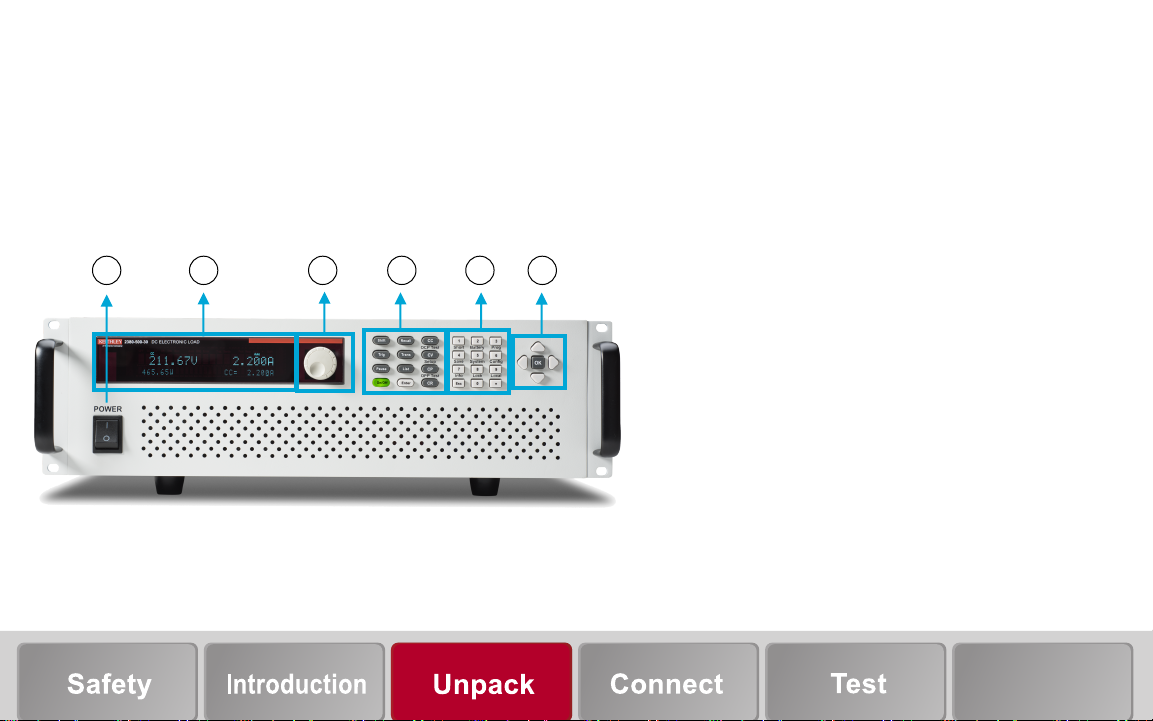
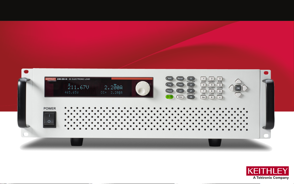
Front‑panel overview
The front panel of the instrument is shown in the following
gure.
1 32 65
4
The items in the gure are:
1 Power on/o switch
2 Display
3 Navigation control
4 Function keys
5 Numeric keypad, Esc key, and combination buttons
6 Navigation arrow keys, Enter, Trigger, and On/O
button
Next steps
Page 8

Keypad overview
The front-panel keypad, including function keys, numeric keypad,
combination buttons, and the Esc key, is shown in the next gure.
Button descriptions
: Enables access to secondary functions
: Recalls stored instrument settings
: Sets the load to trigger mode for list and transient
functions
: Congures transient parameters
: Sets the load to CC mode and congures the current
value
: Sets the load to CV mode and congures the voltage
value
: Sets the load to CP mode and congures the
power value
: Sets the load to CR mode and congures the resistance
value
: Turns the instrument on or o
: Conrms settings
: Up arrow key
: Down arrow key
: Left and right arrow keys
— : Enters numeric values for various parameters
: Pauses the automatic test
: Congures list parameters
: Decimal point
: Cancels the present action and returns to the previous
menu
Page 9

Rear‑panel overview
The rear‑panel interface is shown in the next gure. Descriptions of
the options are provided in the following table.
1
9
8765432
No. Description
1 Input terminals
2 Remote sense terminals, external trigger, and programming input
terminals
3 Cooling fan
4 RS‑232 interface
5 USB port
6 GPIB interface
7 Line voltage selector
8 AC socket
9 Protective ground terminal
Next steps
Page 10

Connect the instrument
Important test system safety information
This product is sold as a stand-alone instrument that may become
part of a system that could contain hazardous voltages and
energy sources. It is the responsibility of the test system designer,
integrator, installer, maintenance personnel, and service personnel
to make sure the system is safe during use and is operating
properly.
It is important that you consider the following factors in your
system design and use:
• The international safety standard IEC 61010-1 denes voltages
as hazardous if they exceed 30 V
for equipment rated for dry locations. Keithley Instruments
products are only rated for dry locations.
• Read and comply with the specications of all instruments
in the system. The overall allowed signal levels may be
constrained by the lowest rated instrument in the system.
For example, if you are using a 500 V power supply with a
300 VDC rated switch, the maximum allowed voltage in the
system is 300 VDC.
• Make sure any test xture connected to the system protects the
operator from contact with hazardous voltages, hot surfaces,
and sharp objects. Use shields, barriers, insulation, and safety
interlocks to accomplish this.
and 42.4 V
RMS
, or 60 VDC
PEAK
• Cover the device under test (DUT) to protect the operator
from ying debris in the event of a system or DUT failure.
• Double-insulate all electrical connections that an operator can
touch. Double insulation ensures the operator is still protected
even if one insulation layer fails. Refer to IEC 61010-1 for
specic requirements.
• Make sure all connections are behind a locked cabinet door
or other barrier. This protects the system operator from
accidentally removing a connection by hand and exposing
hazardous voltages. Use high-reliability fail-safe interlock
switches to disconnect power sources when a test xture
cover is opened.
• Where possible, use automatic handlers so that operators
are not required to access the DUT or other potentially
hazardous areas.
• Provide training to all users of the system so that they
understand all potential hazards and know how to protect
themselves from injury.
To keep users safe, always read and follow all safety warnings
provided with each of the instruments in your system.
Page 11

Install the instrument
Connect line power
You can use a 2380-500-30 or 2380J-500-30 instrument on a
bench or in a rack. See the instructions that came with your
rack-mount kit if you are installing the programmable DC
electronic load in a rack.
To prevent damaging heat build-up and ensure specied
performance, make sure there is adequate ventilation and air ow
around the instrument to ensure proper cooling. Do not cover the
ventilation holes on the top, sides, or bottom of the instrument.
Make sure the instrument is positioned so that it is easy to reach
any disconnecting devices, such as the power cord and the
power switch.
Operating the instrument on an incorrect line voltage
may cause damage to the instrument, possibly voiding the
warranty.
The instrument operates at 100 V, 115 V, 220 V, or 230 V with
a frequency of 50 Hz or 60 Hz. Make sure that the AC line
voltage indicator in the center of the rear-panel power module
matches the AC line voltage in your facility, as shown in the
following gure.
AC line voltage
indicator
Next steps
Page 12

Connect line power
The power cord supplied with the Model 2380-500-30 or
2380J-500-30 instrument contains a separate protective
earth (safety ground) wire for use with grounded outlets.
When proper connections are made, the instrument chassis
is connected to power-line ground through the ground wire
in the power cord. In addition, a redundant protective earth
connection is provided through a screw on the rear panel.
This terminal should be connected to a known protective
earth. In the event of a failure, not using a properly grounded
protective earth and grounded outlet may result in personal
injury or death due to electric shock.
Do not replace detachable MAINS supply cords with
inadequately rated cords. Failure to use properly rated cords
may result in personal injury or death due to electric shock.
To connect line power:
1. Make sure the front-panel power switch is in the o (0) position.
2. On the rear panel, select the correct voltage level (230 V,
115 V, or 100 V).
3. Connect the socket of the supplied power cord to the power
connection on the rear panel.
4. Connect the plug of the power cord to a grounded AC outlet.
Turn on the instrument
Turn on the instrument by pressing the front-panel POWER switch
so that it is in the on (|) position.
Page 13

Test the instrument
Connections for testing
Wires for connection to the rear‑panel input terminals and sense
terminals must be 26 AWG to 10 AWG.
The wire must be heavy enough not to overheat while
carrying the short‑circuit input current of the unit. Make sure
to meet the wiring requirements described above.
Two‑wire connections
Two‑wire connections are used for basic operations when
maximum precision is not required. Keep the wire as short
as possible to reduce wire resistance. If you want higher
measurement precision, use four‑wire remote sense connections.
To connect the DUT to the load using a two‑wire connection:
1. Remove the protective covers from the input terminals, as
shown in the following gure.
Next steps
Page 14

2. Connect the cables to the two input terminals, as shown in
the following gure.
3. Mount the protective covers to the two input terminals.
4. Connect the other end of the cables to the DUT. The red
cable is connected to the positive electrode and the black
cable is connected to the negative electrode.
Page 15

Failure to install the protective cover may result in personal
injury or death due to electric shock.
Four‑wire remote sense connections
For higher measurement precision, you can use four‑wire remote
sense connections.
To connect the DUT to the load using four‑wire remote sense
connections:
1. Remove the protective cover from input terminals, as shown
in the following gure.
2. Connect the input cables to the terminals as shown in the
following gure.
Next steps
Page 16

3. Mount the protective covers to the input terminals, as shown
in the following gure.
4. Connect the sense cables to the SENSE + and SENSE –
screw terminal connectors.
5. Connect the other end of the cables to the DUT. The red
cables are connected to the positive electrode and the black
cables are connected to the negative electrode.
6. Connect the DUT to the remote sense terminals on the rear
panels, as shown in the adjacent wiring diagram.
Failure to install the protective cover may result in personal
injury or death due to electric shock.
Input terminals on the
rear panel
+
Remote sense terminals
on the rear panel
–
Device under
test
–
+
+
–
Page 17

Front‑panel user interface overview
The front‑panel user interface gives you quick access to
measurement settings, system conguration, instrument status,
and other instrument functionality.
Home screen overview
When you turn on the instrument, you see the home screen, show
in the following gure.
0.000V 0.000A
0.00W CC=0.000A
The following options are displayed: Initialize, Power‑ON, Buzzer,
Knob, Trigger, Display, Communication, and Protocol.
To select an option, use the left‑right arrow keys or use the knob
to select an option. Press
Press
The following options are displayed: Von, Protect, Measure,
CR‑LED, Remote‑Sense, and Ext‑Program.
+ on the front panel to show the
CONFIG MENU.
and congure the parameters.
The top row on the home screen displays the actual input voltage
and current values.
The second row on the home screen displays the actual power
value and the present (voltage, power, resistance) setting values.
Menu screen overview
Press + on the front panel to display the
SYSTEM MENU screen.
To select an option, use the left‑right arrow keys or use the knob
to select an option. Press
and congure the parameters.
Next steps
Page 18

The programmable DC electronic load allows you to perform the
following measure functions:
• Short function: Simulate a short circuit with an input.
Front‑panel key combinations for measurement functions are:
+ Short: Enable/Disable short function.
• Transient mode: Conduct a dynamic response time test for a
power supply.
• OCP Function: Conduct an automatic test for OCP conditions.
• OPP Function: Conduct an automatic test for OPP conditions.
• Battery mode: Conduct a battery capacity test by sinking a
xed current load.
• CR‑LED mode: Conduct an output current test for an LED
power supply.
• Measure mode: Conduct a rising/falling time test for a power
supply or a fuse melting time test.
• Autotest function: Conduct an automatic test with various
modes.
+ Battery: Congure battery test parameters.
+ Prog: Congure autotest parameters.
+ OCP Test: Congure OCP parameters.
+ Setup: Congure maximum voltage/current
range for each function.
+ OPP Test: Congure OPP parameters.
Page 19

Specify a measurement range
You can set value ranges for measurements or allow the
instrument to choose the ranges automatically.
The measurement range determines the input during
the measurement, and also aects the precision of the
measurements and the maximum signal that can be measured.
You can specify the current range and voltage range for the
programmable DC electronic load.
To set the range for CC, CV, CR, or CP from the front panel:
1. Press the CC, CV, CR, or CP key.
2. Press
3. Set the range of each parameter. Values are shown in the
following table.
4. Press
+ .
.
See the “Constant‑status operation mode” section of the Model
2380-500 -30 Programmable DC Electronic Load Instruments
User’s Manual (part number 2380‑500‑30‑900‑01) for additional
details and conguration of specic parameters.
Congure and execute a 2-step linear
list sweep
The following example demonstrates how to set the electronic
load to input a linear list sweep from 1 A to 2 A in two steps. The
values demonstrated in the example are default settings. Each
step in the list sweep remains for ve seconds. The list is stored
in list location 1. The input turns on at 0 A and rmains at 2 A at the
end of list execution.
Model number Current
2380-500-30
2380J-500-30
measurement
ranges
Low range: 0 A to 3 A
High range: 0 A to 30 A
Voltage
measurement ranges
Low range: 0 V to 50 V
High range: 0 V to 500 V
Next steps
Page 20

To congure and run a list sweep using the front panel:
1. Press
. The following is displayed.
LIST
On Recall Edit
2. Press . Select Edit. The following is displayed.
4. Set the current range. Press to conrm. The following is
displayed.
EDIT LIST
File Step=2 (2-84)
5. Edit the step count. For example, press to set two
steps, and then press
displayed.
to conrm. The following text is
EDIT LIST
High-Rate Low-Rate
3. Press . Select High ‑Rate. Press to conrm. The
following is displayed.
EDIT LIST
Current Range=0.000A
EDIT LIST
Step 001 Level=1A
6. Edit the current value for step 1. Press
following text is displayed.
EDIT LIST
Step 001 Rate=0.1A/uS
to conrm. The
Page 21

7. Edit the current slope for step 1. Press to conrm. The
following text is displayed.
EDIT LIST
Step 001 Width=5S
10. Edit the current slope for step 2. Press to conrm. The
following text is displayed.
EDIT LIST
Step 002 Width=5S
8. Edit the width time for step 1. Press to conrm. The
following text is displayed.
EDIT LIST
Step 002 Level=2A
9. Edit the current value for step 2. Press
following text is displayed.
to conrm. The
EDIT LIST
Step 002 Rate=0.1A/uS
11. Edit the width time for step 2. Press to conrm. The
following text is displayed.
EDIT LIST
Repeat Count=1
12. Edit the list repeat times. Press to conrm. The
following text is displayed.
EDIT LIST
Save List File=1 (1-9)
Next steps
Page 22

13. Save the list le. Press to conrm. The following text is
displayed.
To execute a list sweep using a stored list:
1. Press
.
LIST
On Recall Edit
14. Press . Select On. Press to conrm. The Trig
indicator turns on.
15. Press
16. Press
17. To quit list operations, press CC, CV, CR, or CP.
to turn on the load input.
to generate a trigger signal.
LIST
On Recall Edit
2. Press to move to Recall. Press to conrm.
The following is displayed.
Recall List File=1
3. Select the pre‑saved list le. Press to conrm. The
following is displayed.
LIST
On Recall Edit
Page 23

4. Press . Select O. Press to change the setting
to ON. The Trig indicator light turns on.
5. Press
6. Press
to turn on the load input.
to run the list.
Next steps
Page 24

Page 25

Next steps
Refer to the Model 2380-500 -30 Programmable DC
Electronic Load Instruments User’s Manual (part number
2380‑500‑30‑900‑01) for detailed information about all features of
the instrument.
Also see tek.com/keithley for support and additional information
about the instrument.
Next steps
Page 26

Contact information:
Australia* 1 800 709 465
Austria 00800 2255 4835
Balkans, Israel, South Africa, and other
ISE countries +41 52 675 3777
Belgium* 00800 2255 4835
Brazil +55 (11) 3759 7627
Canada 1 800 833 9200
Central East Europe / Baltics
+41 52 675 3777
Central Europe / Greece +41 52 675 3777
Denmark +45 80 88 1401
Finland +41 52 675 3777
France* 00800 2255 4835
Germany* 00800 2255 4835
Hong Kong 400 820 5835
India 000 800 650 1835
Indonesia 007 803 601 5249
Italy 00800 2255 4835
Japan 81 (3) 6714 3010
Luxembourg +41 52 675 3777
Malaysia 1 800 22 55835
Mexico, Central/South America, and
Caribbean 52 (55) 56 04 50 90
Middle East, Asia, and North Africa
+41 52 675 3777
The Netherlands* 00800 2255 4835
New Zealand 0800 800 238
Norway 800 16098
People’s Republic of China 400 820 5835
Philippines 1 800 1601 0077
Poland +41 52 675 3777
Portugal 80 08 12370
Republic of Korea +82 2 565 1455
Russia / CIS +7 (495) 6647564
Singapore 800 6011 473
South Africa +41 52 675 3777
Spain* 00800 2255 4835
Sweden* 00800 2255 4835
Switzerland* 00800 2255 4835
Taiwan 886 (2) 2656 6688
Thailand 1 800 011 931
United Kingdom / Ireland* 00800 2255 4835
USA 1 800 833 9200
Vietnam 12060128
* European toll‑free number. If not
accessible, call: +41 52 675 3777
Find more valuable resources at TEK.COM
Copyright © 2019, Tektronix. All rights reserved.
Tektronix products are covered by U.S. and
foreign patents, issued and pending. Information
in this publication supersedes that in all previously
published material. Specfication and price change
privileges reserved. TEKTRONIX and TEK are
registered trademarks of Tektronix, Inc. All other
trade names referenced are the service marks,
trademarks, or registered trademarks of their
respective companies.
*P2380-500-30-903-01B*
2380-500-30-903-01 Rev. B / March 2019
 Loading...