

Page 1

TM 9-6625-2801-14&P
TECHNICAL MANUAL
OPERATOR’S, ORGANIZATIONAL,
DIRECT SUPPORT, AND GENERAL SUPPORT
MAlNTENANCE MANUAL (INCLUDING MAINTENANCE REPAIR PARTS LIST)
FOR
TEST SET,
TEKTRONIX
NSN 6625-04-084-3855
TEKTRONIX, INC.
ELECTRICAL
TYPE 1502-1
HEADQUARTERS, DEPARTMENT OF THE ARMY
AUGUST 1981
Page 2
WARNING
DRY CLEANING SOLVENT
Dry cleaning solvent or mineral spirits paint thinner is flammable
and should not be used near an open flame.
should be provided when these materials are used.
Fire extinguishers
Use only in
well-ventilated areas.
WARNING
Be extremely careful when working in the vicinity of batteries
when the battery case is open.
Do not use uninsulated tools.
Do not wear rings or watches. Metal articles will, if allowed
to contact connectors, cause severe arcing with possible injury
to personnel and damage to the battery.
Page 3

TM 9-6625-2801-14&P
TECHNICAL MANUAL
NO. 9-6625-2801-14&P
DIRECT SUPPORT, AND GENERAL SUPPORT
MAINTENANCE MANUAL (INCLUDING MAINTENANCE REPAIR PARTS LIST)
You can help improve this manual. If you find any mistake
or if you know of a way to improve the procedures, please
let us know.
Changes to Publication and Blank Forms) , or DA Form
2028-2 located in the back of this manual direct to:
Commander, U.S. Army Armament Materiel Readiness
Command, ATTN:
A reply will be furnished to you.
HEADQUARTERS
DEPARTMENT OF THE ARMY
Washington, DC, 20 August 1981
OPERATOR’S , ORGANIZATIONAL,
FOR
TEST SET, ELECTRICAL
TEKTRONIX TYPE 1502-1*
REPORTING OF ERRORS
Mail your letter, DA Form 2028 (Recommended
DRSAR-MAS , Rock Island, IL 61299.
1
CHAPTER
Section
CHAPTER
Section
CHAPTER
Section
*NOTE
Throughout the text,
is in lieu of the authorized Federal nomenclature.
INTRODUCTION
General . . . . . . . . . . . . . . . . . . . . . . . . . . . . . .
I.
II.
Description . . . . . . . . . . . . . . ....... . . . .
2
OPERATING INSTRUCTIONS
I.
Controls and Indicators . . . . . . . . . . . . . . . . . . .
Operation . . . . . . . . . . . . . . . . . . . . . .......
II.
3
SERVICE AND PREVENTIVE MAINTENANCE
I.
Service on Receipt of Material . . . . . . . . . . . . . . .
II. Repair Parts,
III.
Lubrication . . . . . . . . . . . . . . . . . . . . . . . . . . .
IV.
Preventive Maintenance . . . . . . . . . . . . . . . . .
this is referred to as a Time Domain Reflectometer or a TDR. This
Special Tools and Equipment . . . . . .
Paragraph
1-1
1-6
2-1
2-2
3-1
3-3
3-4
3-5
Page
1-1
1-1
2-1
2-3
3-1
3-1
3-1
3-1
i
Page 4

TM 9-6625-2801-14&P
CHAPTER
Section
CHAPTER
Section
CHAPTER
Section
CHAPTER
Section
CHAPTER
Section
4
5
I.
II.
III.
6
I.
II.
7
I.
II.
8
I.
II.
9
I.
II.
III.
Paragraph
FUNCTIONAL ANALYSIS . . . . . . . . . . . . . . . . . . . . 4- 1
PERFORMANCE CHECKS/FAULT ISOLATION
General . . . . . . . . . . . . . . . . . . . . . . . . . . . . . . . . . . 5-1
Performance Checks . . . . . . . . . . . . . . . . . . . . . . . . 5-2
Fault Isolation . . . . . . . . . . . . . . . . . . . . . . . . . . . . . 5-5
MAINTENANCE INSTRUCTIONS
General . . . . . . . . . . . . . . . . . . . . . . . . . . . . . . . . . . 6-1
Maintenance Instructions . . . . . . . . . . . . . . . . . . . . 6-2
REPAIR INSTRUCTIONS
General . . . . . . . . . . . . . . . . . . . . . . . . . . . . . . . . . . 7-1
Repair of TDR . . . . . . . . . . . . . . . . . . . . . . . . . . . . . 7-3
FINAL INSPECTION
General . . . . . . . . . . . . . . . . . . . . . . . . . . . . . . . . . . 8-1
Final Inspection Checks. . . . . . . . . . . . . . . . . . . . . 8-2
PREPARATION FOR SHIPMENT AND STORAGE
Preparation for Travel.. . . . . . . . . . . . . . . . . . . . . 9-1
Shipment . . . . . . . . . . . . . . . . . . . . . . . . . . . . . . . . . 9-2
Storage . . . . . . . . . . . . . . . . . . . . . . . . . . . . . . . . . . 9-3
Page
4-1
5-1
5-1
5-11
6-1
6-1
7-1
7-1
8-1
8-1
9-1
9-1
9-1
APPENDIX
A
REFERENCES
B
MAINTENANCE ALLOCATION CHART (MAC)
C
MAINTENANCE REPAIR PARTS LIST
A-1
B-1
C-1
A-1
B-1
C-1
ii
Page 5

LIST OF ILLUSTRATIONS
TM 9-6625-2801-14&P
Figure
1-1
2-1
2-2
2-3
2-4
2-5
2-6
2-7
2-8
2-9
2-10
2-11
2-12
4-1
4-2
5-1
5-2
5-3
5-4
5-5
5-6
5-7
5-8
5-9
5-10
7-1
C-1
C-2
Title
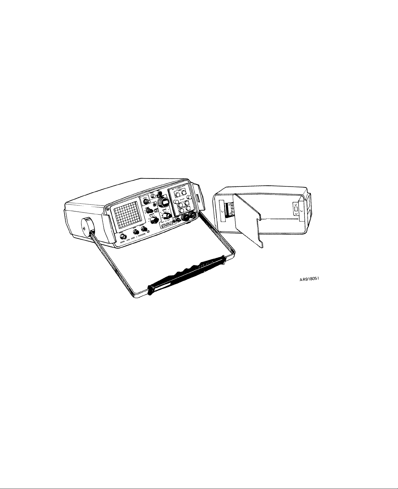
Time domain reflectometer, Tektronix 1502-1, cover removed. . . . . .
TDR front panel controls and indicators . . . . . . . . . . . . . . . . . . . . . .
Battery connector polarity . . . . . . . . . . . . . . . . . . . . . . . . . . . . . . . .
230 Vac transformer wiring . . . . . . . . . . . . . . . . . . . . . . . . . . . . . . . . .
Incident and reflecting pulses.. . . . . . . . . . . . . . . . . . . . . . . . . . . . .
X-Y output module strap.... . . . . . . . . . . . . . . . . . . . . . . . . . . . . . .
Crt display of pulse . . . . . . . . . . . . . . . . . . . . . . . . . . . . . . . . . . . . . .
TDR display of R
vs ZO . . . . . . . . . . . . . . . . . . . . . . . . . . . . . . . . . .
L
Impedance nomograph . . . . . . . . . . . . . . . . . . . . . . . . . . . . . . . . . . . . . .
Open able . . . . . . . . . . . . . . . . . . . . . . . . . . . . . . . . . . . . ........
Shorted cable . . . . . . . . . . . . . . . . . . . . . . . . . . . . . . . . . . . . . . . . . . .
Crimped cable . . . . . . . . . . . . . . . . . . . . . . . . . . . . . . . . . . . . . . . . . . .
Frayed cable . . . . . . . . . . . . . . . . . . . . . . . . . . . . . . . . . . . . . . . . . . . .
Simplified block diagram.. . . . . . . . . . . . . . . . . . . . . . . . . . . . . . . . . .
Simplified sampling diagram . . . . . . . . . . . . . . . . . . . . . . . . . . . . . . . .
Pulse display . . . . . . . . . . . . . . . . . . . . . . . . . . . ...... . . . . . . . . .
Jitter check . . . . . . . . . . . . . . . . . . . . . . . . . . . . . . . . . . . . . . . . . . . .
Position check . . . . . . . . . . . . . . . . . . . . . . . . . . . . . . . . . . . . . . . . . . .
Rise time and fall time... . . . . . . . . . . . . . . . . . . . . . . . . . . . . . . . . .
Power Supply board test points and adjustments . . . . . . . . . . . . . . .
Pulse display . . . . . . . . . . . . . . . . . . . . . . . . . . . . . . . . . . . . . . . . . . .
Loop gain adjustments . . . . . . . . . . . . . . . . . . . . . . . . . . . . . . . . . . . .
PC board location . . . . . . . . . . . . . . . . . . . . . . . . . . . . . . . . . . . . . . . .
Vertical amplifier/slow ramp board . . . . . . . . . . . . . . . . . . . . . . . . . .
Output amplifier board fog adjustment . . . . . . . . . . . . . . . . . . . . . . . .
Power supply board DC fuse location . . . . . . . . . . . . . . . . . . . . . . . .
Replaceable electrical parts . . . . . . . . . . . . . . . . . . . . . . . . . . . . . . . .
Standard accessories . . . . . . . . . . . . . . . .. . ..... .......
Page
1-0
2-1
2-4
2-4
2-5
2-6
2-8
2-9
2-9
2-10
2-10
2-10
2-11
4-1
4-2
5-2
5-3
5-4
5-4
5-6
5-7
5-8
5-9
5-9
5-10
7-1
C-4
C-5
Number
1-1
1-2
2-1
5-1
6-1
8-1
C-1
C-2
LIST OF TABLES
Title
Page
TDR accessories storage. . . . . . . . . . . . . . . . . . . . . . . . . . . . . .. ...2-2
Tabulated data system... . . . . . . . . . . . . . . . . . . . . . . . . . . . . . . . ...1-2
TDR front panel controls and indicators . . . . . . . . . . . . . . . . . . . . . . . 2-2
TDR troubleshooting procedure . . . . . . . . . . . . . . . . . . . . . . . . . . . ...5-11
Maintenance effort . . . . . . . . . . . . . . . . . . . . . . . . . . . . . . . . . . . . . ...6-1
TDR final inspection checks . . . . . . . . . . . . . . . . . . . . . . . . . . . . . . ...8-1
Replaceable electrical parts . . . . . . . . . . . . . . . . . . . . . . . . . . . . . . . . ..C-3
Standard accessories . . . . . . . ............. ...... .. . . C-3
This technical manual is an authentication of the manufacturers’
commercial literature and does not conform with the format and
content specified in AR 310-3, Military Publications. This
technical manual does, however, contain available information
that is essential to the operation and maintenance of the
equipment.
iii/(iv blank)
Page 6

Page 7

TM 9-6625-2801-14&P
INSTRUCTIONS FOR REQUISITIONING PARTS
NOT IDENTIFIED BY NSN
When requisitioning parts not identified by National Stock Number, it
is mandatory that the following information be furnished the supply
officer.
1
- Manufacturer’s Federal Supply Code Number - 80009
2
- Manufacturer’s Part Number exactly as listed herein.
Nomenclature exactly as listed herein, including
3-
dimensions, if necessary.
4
- Manufacturer’s Model Number. Tektronix Type 1502-1
5-
Manufacturerfs Serial Number (End Item)
6
- Any other information such as Type, Frame Number, and
Electrical Characteristics, if applicable.
7
- If DD Form 1348 is used, fill in all blocks except 4, 5,
6, and Remarks field in accordance with AR 725-50.
Complete Form as Follows:
(a) In blocks 4, 5,
Supply Code Number - 80009, followed by a colon and
manufacturer’s Part Number for the repair part.
(b) Complete Remarks field as follows:
Noun:
For:
Manufacturer:
Model:
Serial: (of end item)
Any other pertinent information such as Frame
Number, Type, Dimensions, etc.
1502-1
and 6, list manufacturer's Federal
(nomenclature of repair part)
NSN:
Tektronix, Inc.
P.O. Box 500
Beaverton, Oregon 97005
6625-01-084-3855
v
Page 8
TM 9-6625-2801-14&P
1-0
Figure 1-1. Time domain reflectometer, Tektronix1502-1, cover removed
Page 9

CHAPTER 1
INTRODUCTION
TM 9-6625-2801-14&P
Section I.
1-1. Scope.
a. Purpose.
ual is to provide information and instruction for the direct support maintenance
of the Time Domain Reflectometer, Tek-
tronix 1502.1 (hereafter referred to as
the TDR) including accessory equipment
and external test cable assemblies (see
figure 1-1),
b. Content Summary. This manual
contains the following information:
(1)
A description of the equipment.
Corrective and preventive main-
(2)
tenance
dures.
tions (appendix A).
instructions.
Checkout procedures.
(3)
(4)
Repair instructions.
(5)
Shipment and storage proce-
(6)
References to all related publica-
(7) Maintenance allocation chart
The purpose of this man-
GENERAL
defining maintenance level responsibilities (appendix B).
(8) Maintenance repair parts list
(appendix C).
1-2. Forms and Records. Refer to TM 38750 for instructions on the use of
appropriate forms, records and reports.
1-3. Calibration.
for the TDR are provided in Technical
Bulletin TB 11-6625-2860-35.
1-4. Destruction of Material to Prevent
Enemy Use.
tion of materiel to prevent enemy use refer to TM 750-244-2.
1-5. Reporting Equipment Improvement
Recommendations (EIR). EIR’s will be
prepared using SF 368, Quality Deficiency
Report (QDR).
EIR’s are provided in TM 38-750, The
Army Maintenance Management System
(TAMMS).
to Commander, U.S. Army Armament Materiel Readiness Command, Attention:
DRSAR-MAO, Rock Island, IL 61299. A
reply will be furnished directly to you.
For information on destruc-
EIR’s should be mailed directly
Calibration procedures
Instructions for preparing
Section II.
1-6. Description.
General.
a.
portable Time Domain Reflectometer which
uses radar principles to test cables and
provides a visual display of cable faults.
The test pulses are transmitted via the
CABLE output jack. Reflections are received at the same jack and displayed on
the cathode-ray tube (crt).
The Tektronix 1502-1 is a
DESCRIPTION AND DATA
Calibrated distance controls allow an operator to examine up to 100 feet of cable
with segments as small as 1 foot displayed
horizontally across the 10-division crt
screen.
feet may be examined at 100 feet per division or 200 feet per division. The horizontal crt scale is calibrated directly in distance units from 0. 1 foot per division to
200 feet per division in a 1-2-5 sequence.
Low-loss cables as long as 2000
1-1
Page 10

TM 9-6625-2801-14&P
A 3-digit, direct reading dial indicates
the distance to any cable discontinuity
when the dial is used to horizontally posi–
tion the discontinuity’s reflection to a crt
reference line.
b. Description.
(1) Main case.
gedized portable instrument that can be
used in the field as well as in the labora–
tory.
Class 2, Style A instrument as specified
in MIL-T-28800 were used as a guideline
for the environmental specifications. The
TDR has a ruggedized case that provides
protection when the instrument is stored
in exposed areas.
is not being used, the accessories, including
the Operators manual, may be packed in
the front of the instrument. Table 1-1
indicates which accessories may be placed
in the cover of the TDR.
The requirements for a Type II,
(2) Accessories. When the instrument
The TDR is a rug-
1 TDR Slide Rule
1 TDR Application Note #1
1 X-Y Output Module
1 Instruction Manual 070-1792-00
1-7. Tabulated Data. The characteristics
given in table 1-2 apply after the instrument has been calibrated and will perform
to the requirements given in Chapter 5.
Termination
Pulse Amplitude
Into 50 Load
Accessories Not Stored in Cover
Accessory
Table 1-2.
Characteristics
Tabulated Data System
Tektronix part
number
003-0700-00
062-1538-00
016-0606-00
Performance
50 within ±2%.
225 mV Nominal.
Table 1-1.
Accessories Stored in Cover
Accessories
1 50 BNC Terminator
1 Precision 50 Cable
1 Viewing Hood
1 Operators Manual
1 BNC Connector
Female-to-Female
2 Replacement Fuses
(for front panel)
For 115 Vac
Operation
or
For 230 Vac
Operation (Option 6)
1 Power Cord
1 Filter, Mesh (crt)
TDR Accessories Storage
Tektronix parts
number
011-0123-00
012-0482-00
016-0297-00
070-1790-00
103-0028-00
159-0029-00
159-0054-00
161-0066-00
378-0055-00
Vertical System
Deflection Factor
(7 steps, 1-2-5
sequence)
Accuracy
Gain (screwdriver
control)
Displayed Noise
Low Noise Operation
Horizontal System
Distance Controls
5 /div to 500
/div.
Within ±3%.
At least 3.5:1
from calibrated
point.
±5 or less,
NOISE FILTER
switch “Out”.
±2 or less,
NOISE FILTER
switch “In”.
0 to 2000 feet
total.
1-2
Page 11

TM 9-6625-2801-14&P
Table 1-2.
Tabulated Data
System - Continued
Horizontal System - Continued
Characteristics
Distance Dial
At X1 Multiplier
Range
Accuracy
I
At X1 Multiplier
Range
Accuracy
FEET/DIV Control
At X.1 Multiplier
Range
Scales
(8 steps,
1-2-5
sequence)
Accuracy
(All scale
settings)
(With scale
set at 20
ft/div)
At X1 Multiplier
Range
Scales
(8 steps,
1-2-5
sequence)
Accuracy
All scale
settings Within ±2%.
200 ft/div
scale
Dielectric Scales
SOLID PTFE Vp/V
SOLID POLY
Performance
0 to 100 feet.
Within ±2%, ±0.5
foot.
0 to 1000 feet.
Within ±2 %, ±1
Digit.
To 20 feet/div
0.1 foot/div to 20
feet/div.
Within ±2%.
Within ±1%
To 200 feet/div.
1 foot/div to 200
feet/div.
Within ±1%.
= 0.70
air
V
p/Vair
= 0.66
Characteristics
OTHER-VAR
Accuracy
Recorders
External Recorder
Interface for X-Y
Recorders
Horizontal
Vertical
Pen Lift
Mode 1
Source V
Sink
Mode 2 (inverted
Mode 1)
Source
Sink
Line Voltage
Battery Pack
(C size, 9 cell)
Operation
(+20oC to +25°C
charge and dis–
charge temperature)
Full Charge Time
Performance
V
= 0.55 to 1
p/Vair
Within ±2%.
0.1 V/div;
(source impedance
10 K ).
0.09 to 0.13 V/div
adjustable (source)
impedance 10 k
= 5 V Nominal
s
with R
< 10 mA (V out
< 0.5 V).
Vs = 5 V Nominal
with R
< 0.5 mA (V out
<0.6V).
—
Power System
117 Vac ±20%, 48
to 410 Hz; fused
at 0.3 A.
234 Vac ±20%, 48
to 410 Hz; fused
at 0.15 A.
At least 5 hours.
16 hours
= 10 k
s
= 10 k
s
1-3
Page 12
TM 9-6625-2801-14&P
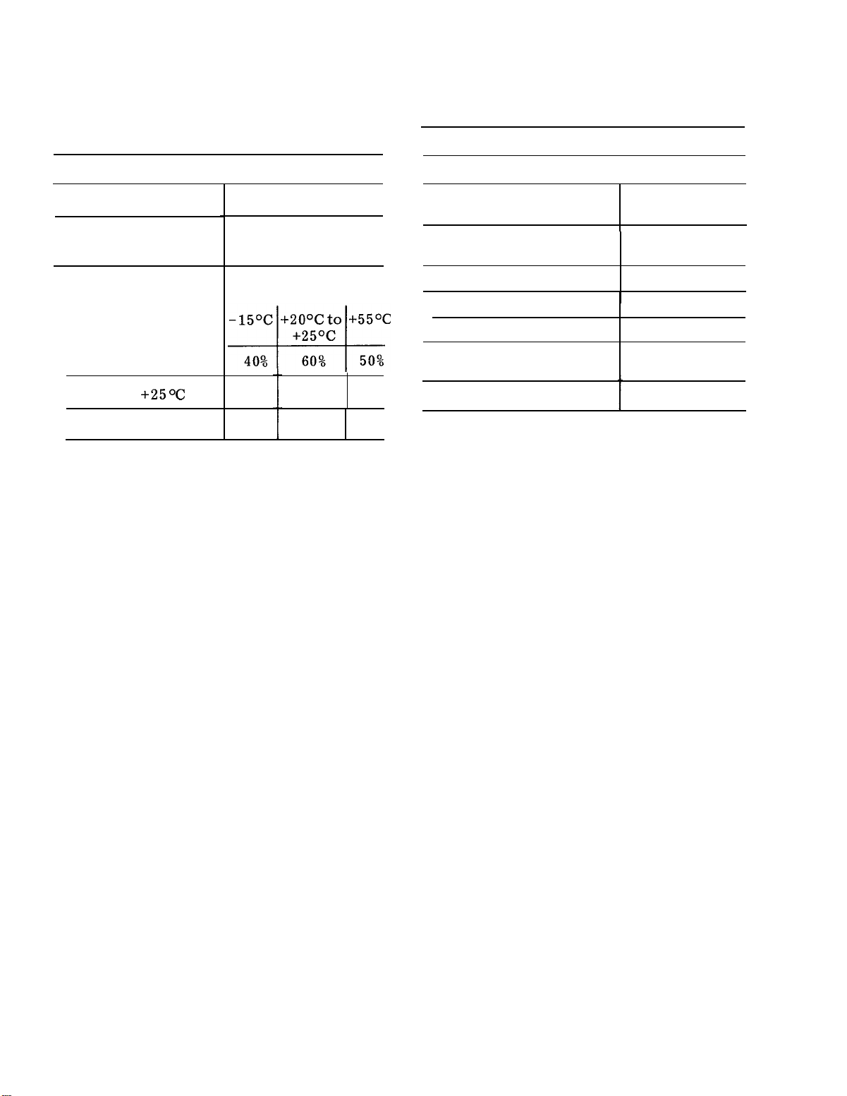
Table 1-2.
Tabulated Data - Continued
Power System - Continued
Characteristics
Typical Charge
Capacity
Charge Temperature
0oC
o
C to +25°C
+20
o
C
+40
Description
Discharge Temperature
65% 100% 85%
40%
65% 55%
Physical Characteristics
Characteristics
Description
Weight with panel cover 18 pounds
and accessories
Without panel cover
16 pounds
and accessories
Height
Width with handle
Without handle
Depth including panel
5.0 inches
12.4 inches
11.8 inches
16.5 inches
cover
Handle extended
18.7 inches
1-4
Page 13
CHAPTER 2
OPERATING INSTRUCTIONS
TM 9-6625-2801-14&P
Section I.
2-1.
tors.
pose of each front panel connector,
pushbutton,
Front Panel Controls and Indica-
A brief description of the pur-
control, and screwdriver
CONTROLS AND INDICATORS
adjustment follows.
controls of the plug-in module is also
included.
location.
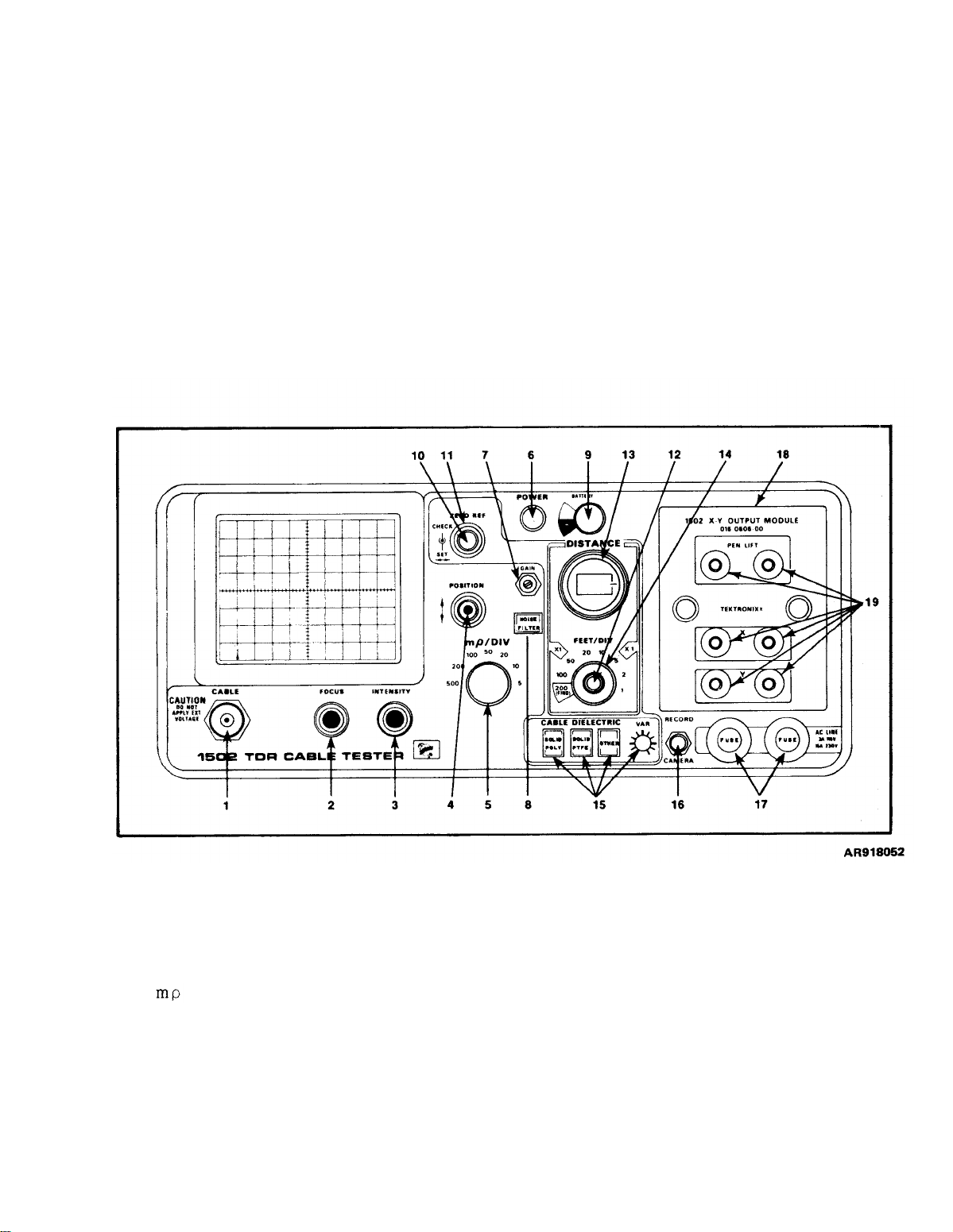
Refer to figure 2-1 for their
A description of the
Legend for fig. 2-1:
1.
CABLE connector
FOCUS control
2.
3.
INTENSITY control
4.
POSITION control
5.
/DIV switch
6.
POWER switch
7.
GAIN adjustment
8.
NOISE FILTER switch
9.
BATTERY meter
10.
ZERO REF CHECK switch
Figure 2-1.
11.
ZERO REF SET control
12.
multiplier switch
13.
DISTANCE control
14.
FEET/DIV switch
15.
CABLE DIELECTRIC switches and
control
16.
RECORD/CAMERA switch
17.
AC LINE fuses
18.
X-Y OUTPUT MODULE
19.
External
TDR front panel controls and
chart recorder controls
indicators
2-1
Page 14

TM 9-6625-2801-14&P
Table 2-1.
Figure 2-1
index no
1
2
3
4
5
6
7
8
TDR Front Panel Controls
and Indicators
Control or
indicator
CABLE
FOCUS
INTENSITY
POSITION/
FINE
/DIV
POWER
GAIN
NOISE
FILTER
Function
BNC Connectordelivers 110 ps
risetime pulse to
the test cable and
receives the re–
fleeted return
pulse.
Adjusts the focus
of the crt elec–
tron beam.
Controls the
brightness of crt
display.
Controls vertical
position of the crt
display. The
outer control is a
coarse adjust–
ment and the
inner control is
a fine adjustment.
Selects the vertical deflection
factor--5 /div
to 500 /div
(5-2-1 sequence).
Push-pull, off-on
switch (pull for
on) – does not
affect the battery
charging circuit.
Screwdriver ad-
just to set the
gain of the verti-
cal amplifier.
Reduces displayed
noise.
rate is reduced by
a factor of 10.
Display
Figure 2-1
index no.
9
10
11
12
13
Control or
indicator
BATTERY
ZERO
REF
CHECK
ZERO
REF
SET
MULTI-
PLIER
DISTANCE
Function
Meter to indicate
the relative charge
of the power pack.
Momentary contact
Pushbutton. When
pushed, checks
the horizontal location of the inci–
dent pulse on the
crt when the DISTANCE dial is
being used.
horizontal pulse
position control
for crt display.
Sets the incident
pulse edge to a
vertical reference
line of the crt
when the DIS-
TANCE dial is at
000 or the ZERO
REF CHECK but-
ton is pushed.
Two-position
switch (red con–
trol) for X.1 or
X1 multiplier.
Affects both the
DISTANCE dial
and the FEET/
DIV control.
Inicates the dis-
tance from the
TDR to the point
on the cable where
the display win-
dow begins. Two
ranges:
at X.1 or 1000
feet at X1. Dis-
abled when the
FEET/DIV is at
200 (FIND).
100 feet
2-2
Page 15
TM 9-6625-2801-14&P
Table 2-1.
Figure 2-1
index no
14
15
16
TDR Front Panel Controls
and Indicators – Continued
Control or
indicator
FEET/DIV
CABLE
DIELECTRIC
SOLID
POLY
SOLID
PTFE
OTHER
VAR
RECORD/
CAMERA
Function
Selects the horizontal deflection
factor:
X1=1 - 200 ft/
div.
X.1=0.1 - 20
ft/div.
Three pushbuttons
and a screwdriver
adjust.
the proper velocity
of propagation.
VAR from 0.55 to
1.0 when the
OTHER pushbutton
is pressed. Fully
cw if for air die–
lectric.
trol has reference
marks every 30°
to indicate relative propagation
constants.
Two-position lever
switch; pushed up
and then released,
it initiates X-Y
Recorder or a
Selects
VAR con-
Figure 2-1
index no.
17
18
19
Control or
indicator
AC LINE
FUSES
X-Y
OUTPUT
MODULE
X, Y,
and PEN
LIFT
Function
Chart Recorder;
pushed down, it
floods the crt during retrace to
display graticule
for photography.
Protection fuses
for line power
and battery charging circuits (0.3
A fuses for 115
Vac; 0.15 A fuses
for 230 Vac).
The standard plugin module for the
TDR. Used to
drive an external
X-Y Chart Recorder.
Six front panel
jacks used for
driving an ex-
ternal X-Y recorder.
are for horizontal drive.
are for vertical
drive.
jacks are for pen
control.
X jacks
Y jacks
PEN LIFT
Section II.
Be extremely careful when working
in the vicinity of batteries when the
battery ease is open. Do not use
uninsulated tools. Do not wear
rings or watches. Metal articles will,
if allowed to contact connectors,
cause severe arcing with possible
injury to personnel and damage to
the battery.
OPERATION
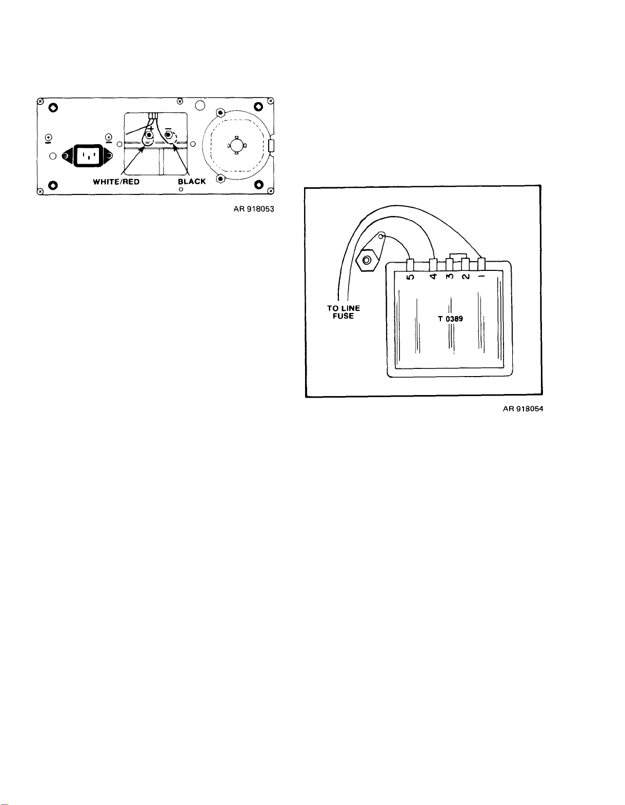
2-2. Operating Power Selection.
When substituting a dc power
supply or external battery for
the battery pack, be sure the
polarity is correct (see figure
2-2).
2-3
Page 16
TM 9-6625-2801-14&P
Figure 2-2. Battery connector polarity
a.
Battery Connections. A 12 Vdc
power supply may be substituted for the
TDR battery pack by removing the pack
from the unit and connecting the power
supply to the terminals inside the battery
pack compartment.
The power pack can be stored at any
temperature between -40oC and +50°C
with the battery cells either fully or
partially charged.
rate of the cell increases with increased
temperature.
will lose about 50% of its charge in 3 to 4
months if stored at +20°C to +25°C.
Therefore, the battery pack should be
completely recharged before using if it
has been stored without power supplied
to its charging circuit for more than a
month.
A fully charged battery
The self-discharge
2-3. Turn-on Procedures.
If crt displays no signal, check
fault isolation paragraph 5-6.
Figure 2-3.
Preparation.
a.
NOTE
230 Vac transformer wiring
When the TDR is wired for 230
Vac, be sure that the two front
panel fuses are changed to 230 V,
0.15A slow-blow fuses and the
proper plug is installed on the
ac cable.
b.
230 Volt Operation. The battery
charger is factory wired for 115 Vac or
230 Vac if Option 6 is ordered. The
standard 115 Vac unit can be changed to
230 Vac operation by rewiring the line
transformer.
per wiring configuration for 230 V operation.
Figure 2-3 shows the pro-
2-4
(1) To gain access to the front panel,
pull the two side latches forward and re-
move cover.
TDR as a stand, position it to raise the
unit to a convenient operating position
(figure 1-1).
(2) The battery pack is fully charged
in 16 hours when connected to an ac power
source and the unit is switched off. The
TDR may be operated while the battery
pack is charging; however, the charging
time will increase.
overcharge if the charger is left on long-
er than 16 hours.
may remain connected to an ac source
without damaging the batteries. Approxi-
mately once a month or every 15 -charge–
discharge cycles, the batteries should be
charged for approximately 24 hours.
Using the handle of the
The batteries will not
Therefore, the TDR
Page 17
Approximately 30 minutes of operating
time can be expected from a 1-hour partial
charge. To avoid reverse charging, the
full 16 hour charge should be completed
in preference to a partial charge whenever possible.
Control Settings (TDR).
b.
(1) Set front panel controls as
follows:
TM 9-6625-2801-14&P
FOCUS
INTENSITY
ZERO REF
POSITION
/DIV
DISTANCE
FEET/DIV
X1-x1
CABLE DIE-
LECTRIC
POWER
(2) Adjust INTENSITY and FOCUS
controls for a clear bright trace.
(3) Adjust POSITION controls to set
trace 2 divisions below horizontal center–
line.
(4) Attach precision 50 cable (012-
0482-00) to CABLE connector (stored in
cover).
(5) Turn ZERO REF SET button ccw
until incident pulse edge is located on a
vertical reference line. The incident
pulse edge is the initial rise of the step
pulse. The vertical reference line may be
any line you choose from center line to
left side of crt graticule. An arrow in
the second vertical line indicates a
commonly used reference line.
The reflected pulse from the open
end of the 50 cable should ap-
pear three horizontal divisions to
right of reference line. Open end
of cable is indicated by start of a
second rise in trace (see figure
2-4).
Midrange
Full range
Fully cw
Midrange
500
000
1
X1
SOLID POLY
ON
NOTE
Figure 2-4. Incident and reflected pulses
(6) Turn ZERO REF SET button
throughout its range to see that the inci–
dent pulse edge can be set on any vertical graticule line.
edge on vertical reference line.
(7) Set DISTANCE dial to 050 and
check that top of step (open cable re–
flection) is displayed.
(8) Press ZERO REF CHECK button
and check that incident pulse edge returns to vertical reference line of graticule.
POSITION controls so top of incident
pulse is on horizontal centerline.
and check for a reduction in displayed
noise as well as a reduction in scan rate.
Reset /DIV to 500, and release (by
depressing a second time) NOISE FILTER
button.
Note crt display; entire crt should be
flooded on retrace to illuminate graticule
when taking photographs. Release
CAMERA switch.
Reset DISTANCE dial to 000.
(9) Change /DIV to 50 and adjust
(10) Press NOISE FILTER pushbutton
(11) Press and hold CAMERA switch.
Set incident pulse
2-5
Page 18
TM 9-6625-2801-14&P
(12) Lift up and hold RECORD switch.
Check that bright spot appears at left
edge of crt.
(13) Release RECORD switch. Slow
scan of spot will trace displayed waveform.
automatically return to its normal mode
of scanning.
When scan is complete TDR will
c.
Control Settings (Accessories).
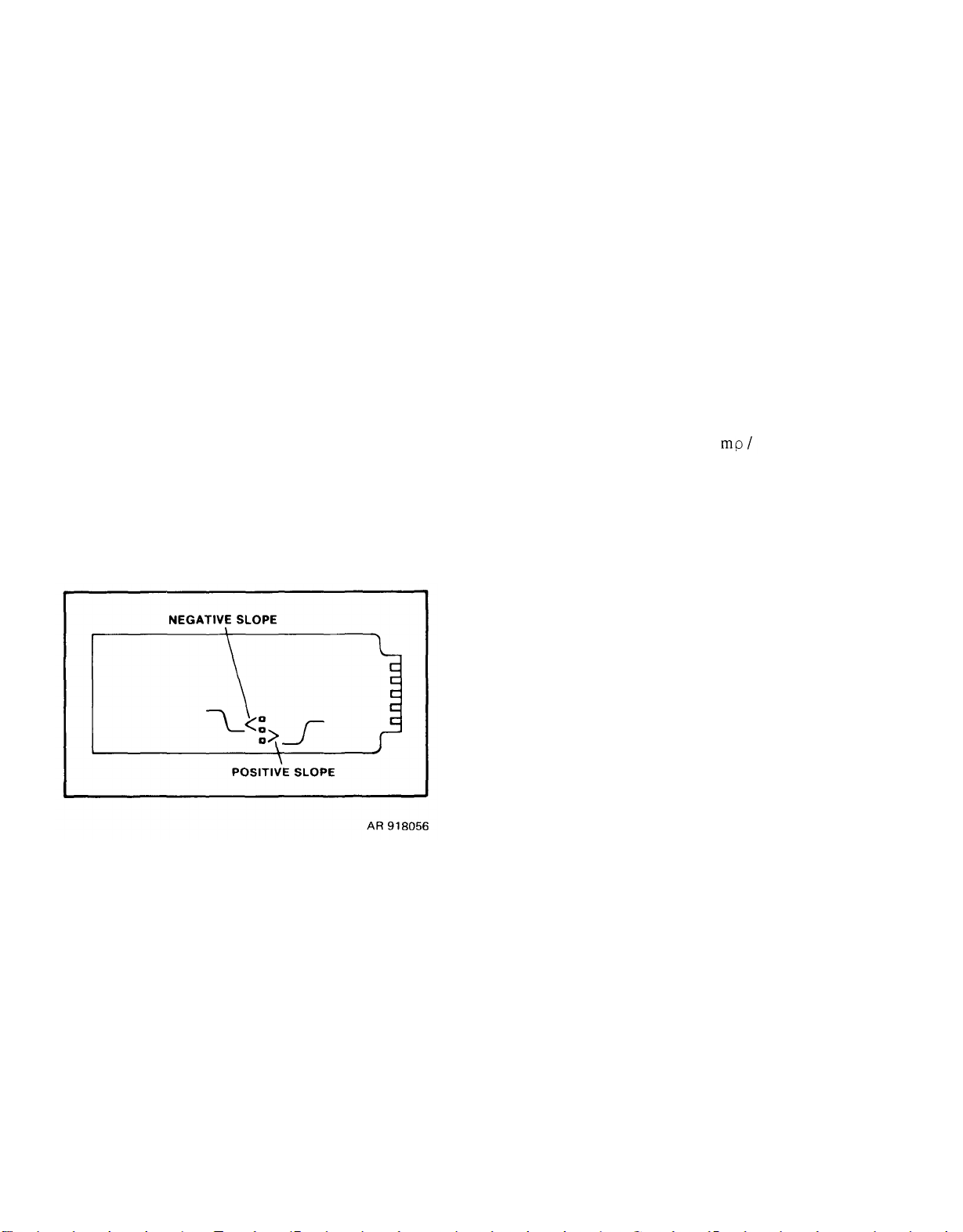
NOTE
The X-Y OUTPUT MODULE is
wired for either a positive or
negative pen lift signal. Be-
fore using the X-Y OUTPUT
MODULE , be sure that the pen
lift circuit on the etched circuit board is properly connected.
Figure 2-5 shows the proper
connection for either a positive
or negative pen lift signal.
(4) To position stylus at desired
position on paper, adjust STYLUS POSITION screw while RECORD/CAMERA
switch is in the RECORD position.
(5) Release RECORD/CAMERA to
precede with recording. Chart record
circuits automatically shut off when recording is completed.
NOTE
In evaluating a graph, the dis-
tance between two dark hori-
zontal lines corresponds to one
vertical division of the crt dis–
play with respect to the
DIV setting; the distance between two dark vertical lines
corresponds to one horizontal
division of the crt display with
respect to the FEET/DIV setting.
d. Use of Accessories.
Figure 2-5.
(1) If not already in place, install
X-Y OUTPUT MODULE into its compartment on front panel of TDR.
(2) Connect X, Y, and PEN LIFT
inputs of recorder to corresponding
jacks of X-Y OUTPUT MODULE.
(3) Position and hold RECORD/
CAMERA switch to RECORD to prepare
for recording.
X-Y output module strap
(1) Mesh Filter for the crt. A mesh
filter is provided with the TDR which
makes viewing of the crt easier when the
unit is being used in the sunlight. This
filter is placed over the crt by sliding it
onto the slots of the crt bezel.
provides shading for the crt and can be
installed over the crt by sliding it down
over the crt bezel sides.
must be removed before the viewing hood
will connect to the crt bezel.
If a Camera Adapter (Tektronix Part
Number 016-0327-00) is attached to the
crt bezel of the TDR, a C–30A/31 cam–
era can be used to take photographs of
the crt display.
illumination, the RECORD/CAMERA
switch must be pushed down and held
while the photograph is being taken.
After the trace is completed the entire crt
is flooded to provide a light background
to allow the dark graticule to appear in
the photograph.
.
(2) Viewing Hood. The viewing hood
The mesh filter
(3) Using a Camera with the TDR.
To obtain graticule
2-6
Page 19

TM 9-6625-2801-14&P
2-4.
the TDR to the BNC connector (CABLE)
on the front panel.
ter as required.
Cable Testing.
Do not connect live circuit cables
to the input of the TDR. Voltages in excess of 5 volts can damage the sampling gate or tunnel
diode.
Bleed cables before connecting
them to the TDR to remove static
charge from them. The 50 ohm
termination and BNC adapter
supplied may be used to bleed
any cable charge.
When testing antennas, be sure
that you are not close to trans-
mitters that can be keyed at the
antennas receiving frequency.
Keying of transmitters in close
proximity can cause damage to
the TDR.
Connecting a Cable for Testing.
a.
(1) Connect cables to be tested by
Use connector/adap-
150 feet long, set
and the multiplier
Use the X.1 multiplier whenever
possible to lessen the effects of
jitter.
(2) Measure the distance between
the incident pulse rise and the reflected
pulse rise.
The distance from the sampling
bridge to the CABLE connector
(2. 5 inches) should be taken into account when measuring
cables less than 2 feet in length.
(3) To more accurately locate the
discontinuity, set the FEET/DIV control
to a lower setting. (The reflected
pulse does not need to be in the display
window).
button and adjust the ZERO REF SET
control so that the incident pulse rise is
set at a convenient vertical reference
graticule line.
contol may have to be readjusted when
changing the FEET/DIV control.
Push the ZERO REF CHECK
the FEET/DIV to 200
at X.1.
NOTE
NOTE
The ZERO REF SET
(2) Adjust FOCUS and INTENSITY
controls for a sharp and bright display
on the crt.
b. Locating a Discontinuity in a Cable.
The DISTANCE dial and the FEET/DIV
control make it possible to evaluate cables
as long as 2000 feet. The entire length
can be displayed directly on the crt if
desired.
only that portion of the trace seen on the
crt will be recorded on the graph. To
check cables using the crt, proceed as
follows:
(1) Set crt display window so it is
longer than the cable under test by set-
ting the FEET/DIV control and the X1/
X.1 control,
If a chart recorder is used,
For example, if the cable is
NOTE
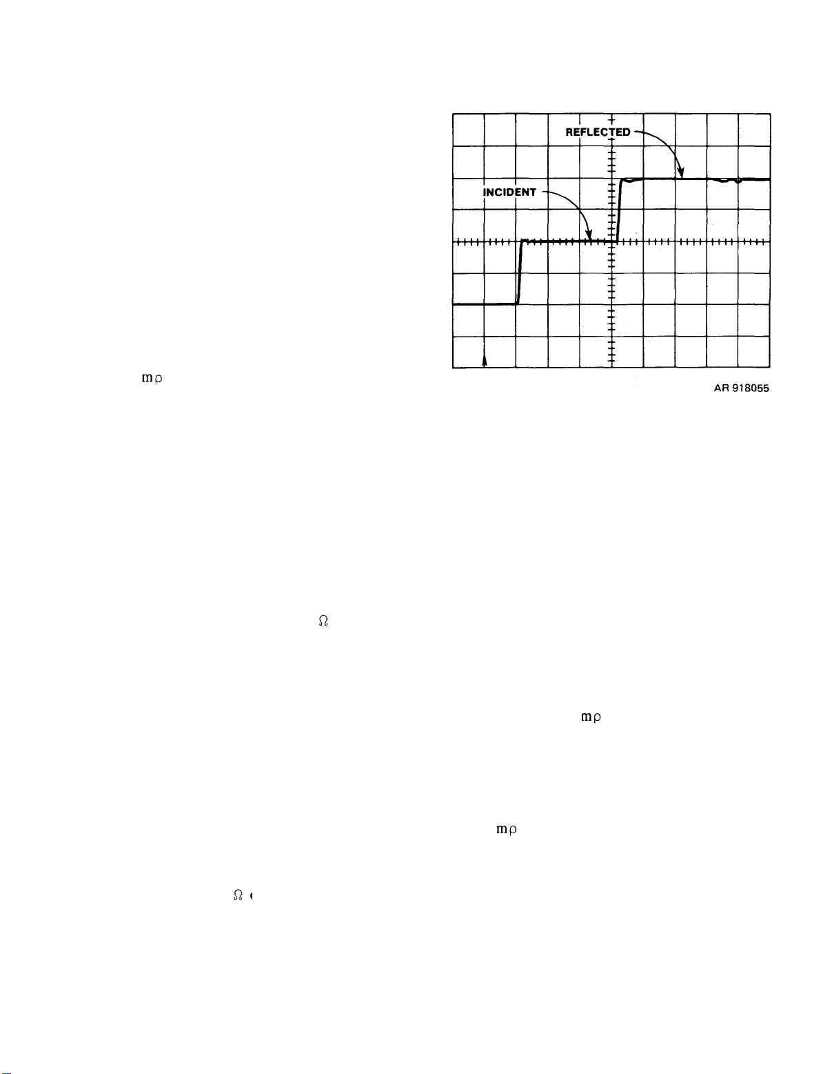
Always set the incident and reflected pulse to the 10% points of
their amplitude (see figure 2-6).
(4) Turn the DISTANCE dial clock-
wise until the reflected pulse is located
on the reference graticule line. The
reading on the DISTANCE dial times the
multiplier gives the length from the
CABLE connector to the end of the cable
(or to the discontinuity).
NOTE
When checking cables longer
than 1000 feet, adjust the DISTANCE dial until the reflected
pulse reaches the right-hand
2-7
Page 20
TM 9-6625-2801-14&P
edge of the graticule, then
add the graticule display distance to that on the DISTANCE
dial for the total length. The
reading of the DISTANCE dial,
plus the number of divisions
(from the reference line) across
the graticule times the FEET/
DIV setting gives the total
length of the cable. Remember
that in the 200 FEET/DIV setting the DISTANCE dial is inoperative.
Figure 2-6. Crt display of pulse
(5) The CABLE DIELECTRIC push-
buttons allow the TDR to accurately locate discontinuities in cables of various
relative propagation velocity constant
(Vp).
brated to check solid polyethylene dielectrics which have a Vp of 0.66. The
SOLID PTFE button is calibrated to check
solid polytetrafluoroethylene (Teflon)
which has a Vp of 0.70. The OTHER
button is variable from 0.55 to 1.00 and
is controlled by the screwdriver adjust–
ment control VAR.
control is turned to the fully clockwise
position, it is calibrated for air dielectrics
which have a Vp of 1.00. If all three of
the CABLE DIELECTRIC buttons are
released, a default condition leaves the
instrument calibrated for air dielectrics
(Vp) = 1.00).
The SOLID POLY button is cali-
When this screwdriver
/DIV control determines the vertical
deflection that can be seen on the crt or
recorded on a graph if a chart recorder
is used.
measure the ratio of the reflected signal
amplitude to the incident signal amplitude
in rho ( ), which is called the voltage
reflection coefficient.
measurement of reflected signal amplitude
and can be used to determine the im–
pedance of a discontinuity. Note that no
reflection is obtained from a cable that
has no discontinuities if the cable is ter-
minated with its characteristic impedance.
If a cable has an open, i.e., a break
(infinite impedance), the reflected step
amplitude is +1 ;
short (zero impedance), the reflected
step amplitude is -1
of a TDR display labeled to identify the
incident and reflected voltage signals.
When =0, the transmission line is ter-
minated by a resistance equal to its
characteristic impedance (Z0) which, in
this case, is 50
the transmission line load is a short. If
the line is terminated by RL > 50
is positive and if the line is terminated by
RL < 50 is negative.
ting reflected pulse amplitude to impe-
dance.
teristic impedance, Z0, of the cable under
test and the load (or the impedance of
the discontinuity), R
Therefore, a can also be defined as:
the cable problems that can be analyzed
with the TDR include opens, shorts, pin-
holes in the cable shield, opens in the
shield, kinks in the cable, mismatched
connectors, and corroded connectors.
c.
Evaluating a Discontinuity. The
This control is calibrated to
Rho ( ) is the
and if a cable has a
(1) Figure 2-7 shows the two parts
.
When equals +1,
(2) Figure 2-8 is a chart for conver-
Rho is dependent on the charac-
, on the cable.
L
Typical Cable Problems. A few of
d.
2-8
Page 21

TM 9-6625-2801-14&P
Figure 2-7.
TDR display of RL vs Z
O
Figure 2-8.
Impedance nomograph
2-9
Page 22
TM 9-6625-2801-14&P
Figures 2-9 through 2-12 show typical
examples of these problems.
Figure 2-9. Open cable
e.
Checking Cables with Other than
50 Ohms Impedance.
(1) Cables with a characteristic
impedance other than 50 can be evalu-
ated by adjusting the GAIN control
(screwdriver adjust) to correct the re-
flected pulse for +1 at the open end of
a cable.
incident pulse will no longer be 1
dance other than 50 , either connect
an impedance–matching adapter (50 to
75 , 50 to 93 50 to 125 etc.) to the
CABLE connector and connect a short
length of cable (with impedance the same
as the adapter, i.e., 75 125 etc.)
to the adapter or connect the cable to be
tested to the CABLE connector. With the
/DIV control set at 500, position the
trace on the graticule so that the display
of the cable appears in the display. Now
When the GAIN is changed, the
.
(2) To reset the GAIN for an impe-
Figure 2-10.
Figure 2-11. Crimped cable
Shorted cable
2-10
Page 23
TM 9-6625-2801-14&P
adjust the GAIN control so that the open
end display (reflected pulse) is set 2
divisions above the cable display (hori-
zontal centerline). This sets the reflected pulse to +1 from the characteristic impedance.
NOTE
If an impedance adapter is not
used, secondary reflections
will re–appear as discontinuities beyond the open end of
the cable.
Figure 2-12.
Frayed cable
2-11/(2-12 blank)
Page 24

Page 25

CHAPTER 3
SERVICE AND PREVENTIVE MAINTENANCE
TM 9-6625-2801-14&P
Section I.
3-1. Unpacking and Inspection. When the TDR is
received, it will be packed in a corrugated cardboard carton. Inside packing and re-enforcement is
also fabricated from corrugated cardboard. Gain
access to the TDR by carefully cutting the sealing
tape on top of the carton, open carton, remove the
top packing, and withdraw TDR from carton,
Carton should be stored for future use in reshipping. Visually inspect the TDR for
Section II.
3–3. Repair Parts. Repair parts are
listed in Appendix C of this manual.
SERVICE UPON RECEIPT OF MATERIAL
damage.
panel and controls for damage. Open inside cover. Remove, unwrap and check
for all items listed in table 1-1 and inspect all items for damage.
3-2. Checkout Procedures. Perform
procedures given in paragraphs 2-3 a
and b to ensure the equipment is in operational condition.
REPAIR PARTS , SPECIAL TOOLS AND EQUIPMENT
Section III.
LUBRICATION
Release cover and inspect front
3-4. General. This equipment does not
require periodic lubrication.
Section IV.
Dry cleaning solvent or mineral
spirits paint thinner is flammable
and should not be used near an
open flame. Fire extinguishers
should be provided when these
materials are used.
ventilated areas.
Use only in well
PREVENTIVE MAINTENANCE
3-5. General.
consists of cleaning, visual inspection,
etc. Preventive maintenance performed
on a regular basis will help improve the
reliability of the instrument. The se-
verity of the environment to which the
TDR is subjected determines the fre-
quency of needed maintenance. A convenient time to perform preventive
maintenance is preceding recalibration of
the instrument.
Preventive maintenance
3-1
Page 26

TM 9-6625-2801-14&P
3-6. Cleaning.
a.
General. Accumulation of dirt in
the instrument can cause overheating and
component breakdown. Dirt on components acts as an insulting blanket and
prevents efficient heat dissipation. It
also provides an electrical conduction
path.
b.
Interior.
in a manner that protects the interior of
the instrument from dust.
When the cabinet is removed,
the watertight integrity may be
compromised.
tions (in this section) on removing and replacing the cabinet.
Therefore, the interior of the TDR
should not require cleaning unless the
unit has been left with the front cover
removed and the plug–in compartment
empty.
terior is to blow off the accumulated dust
with low–pressure air.
that remains with a soft brush or a cloth
dampened with a mild detergent and
water solution.
cator is useful for cleaning in narrow
spaces on circuit boards.
The best way to clean the in-
The TDR is constructed
NOTE
See the instruc-
Remove any dirt
A cotton-tipped appli-
rinsed with clear water.
cumulated on the front panel is best
removed with a small brush or a soft
cloth dampened with a mild detergent and
water solution.
not be used on the front panel.
d.
CRT Implosion Shield. The face of
the crt can be cleaned by using isopropyl
alcohol applied and wiped very gently
dry with lens paper (NSN 6640-00-559-
1385).
3-7.
pack should be inspected every two
months.
be replaced if venting or corrosion has
occurred.
3-8. Water-tight Seals. The TDR is prepared to be operated in any weather
(rain, snow, dust, etc.). To prevent
moisture and dust from getting inside the
instrument, special seals are used around
the pushbuttons,
and rotary controls.
the components on the front panel will
require special resealing procedures to
retain their water–tight integrity.
3-9. Calibration.
measurements, check the calibration
every 120 days.
Procedure Technical Bulletin for Time
Domain Reflectometer, Tektronix Type
1502-1, TB 11-6625-2860-35 for calibration procedures.
Servicing battery. The battery
The entire battery pack should
Abrasive cleaners should
crt, power switches,
To ensure accurate
Refer to Calibration
Loose dust ac-
Removal of any of
Avoid the use of chemical cleaning agent which might damage
the plastics used in this instrument.
contain benzene, toluene, xy–
lene, acetone or similar solvents.
c.
can be washed with soap and water and
Avoid chemicals which
Exterior.
The cabinet exterior
3-2
Page 27

CHAPTER 4
FUNCTIONAL ANALYSIS
TM 9-6625-2801-14&P
4-1.
TDR uses radar principles to check cable
conditions.
the pulses down the cable under test,
and the sampler circuits sample the echos
and provide the vertical signal for display on the crt.
tunnel diode in a 50 ohm strip line (cavity). It contains all biasing and timing
circuits required for operation of tunnel
diode CR1703.
Simplified Circuit Analysis. The
The pulser circuits transmit
Pulser. The pulser is basically a
a.
b.
Sampling.
(1) Sequential equivalent-time sampling is used to develop a display (see
figure 4-1).
a fast ramp and a slow ramp. The fast
ramp is compared to the slow ramp or a
fixed reference to generate trigger pulses for the sampler and the pulser respectively.
the pulser and sampler comparators.
These comparisons are made by
Two ramps are generated,
Figure 4-1.
Simplified block diagram
4-1
Page 28

TM 9-6625-2801-14&P
(2) A short time after the pulser
transmits the step pulse into the cable
under test, depending on the amplitude
of the slow and fast ramps, a sampling
trigger from the sampler comparator
causes the sampler to sample–and–hold
the voltage level appearing at that time.
This voltage is taken at the point where
the sampler is connected to the 50 ohm
strip line.
fied and sent through the vertical amplifiers to the crt.
(3) The slow ramp generator pro-
vides the horizontal sweep for the crt
and, combined with the vertical sample,
This voltage sample is ampli-
provides a display of the sampled value.
Ensuing sampling triggers taken later
during the next fast ramp time, cause
additional samples to be displayed next to
the first one, until a line of very short
dashes is formed across the crt, appearing as a solid line (figure 4-2).
c.
Chart Recorder.
(1) The amplified vertical and ramp
signals are also sent to X–Y interface
connectors. These signals, along with a
pen lift control signal, provide the information for driving external X-Y record-
ers.
4-2
Figure 4-2.
Simplified sampling diagram
Page 29

CHAPTER 5
PERFORMANCE CHECKS/
FAULT ISOLATION
Section I. GENERAL
TM 9-6625-2801-14&P
5-1. Introduction.
detailed performance checks for the TDR.
Performance checks may be made without
5-2. Preparation for Performance Checks.
a.
Ensure that a battery is installed in
the TDR.
b. Connect TDR to ac power source.
c.
Pull the POWER switch to turn the
unit on.
the relative level of charge on the battery
pack. If the battery pack is fully charged
(charged for 16 hours), the BATTERY
meter needle will be approximately at the
top mark on the meter.
5– 3. Performance Checks.
a.
graph 5-2 and then set front panel con-
trols as follows:
INTENSITY
ZERO REF
POSITION Midrange
/DIV
DISTANCE
NOISE FILTER
FEET/DIV
MULTIPLIER X1
CABLE DIELECTRIC
b. Preset the POSITION and GAIN con-
trols so the trace is on screen and the
BATTERY meter will indicate
Perform procedures given in para-
SOLID POLY
SOLID PTFE
Other
VAR
This chapter provides
Section II.
Fully cw
Fully cw
500
000
Out
200
In
Out
Out
Fully cw
PERFORMANCE
any test equipment. Performing the
checks will also identify a fault present
in the
equipment.
CHECKS
amplitude is approximately 4 divisions.
Adjust the FOCUS and INTENSITY controls for a clear, bright trace.
FEET/DIV
MULTIPLIER
CABLE DIELECTRIC
SOLID POLY
SOLID PTFE
Other
VAR
b. Preset the POSITION and GAIN
controls so the trace is on screen and the
amplitude is approximately 4 divisions.
Adjust the FOCUS and INTENSITY con-
trols for a clear, bright trace.
c.
Adjust the GAIN control so that the
total amplitude of the display is exactly 4
divisions.
depot for repair.
d.
MULTIPLIER to X1.
e.
counterclockwise to locate the pulse at
center screen.
form as shown in figure 5-1a. If the
display is not correct, forward TDR to
depot for repair.
f. Connect the precision 50 terminator
(Tektronix Part No. 011-0123-00) to the
CABLE connector. Turn the GAIN control
fully counterclockwise and note the
If incorrect, forward TDR to
Set FEET/DIV control to 2 and
Turn the ZERO REF SET control
Check for correct wave-
200
X1
In
Out
Out
Fully cw
5-1
Page 30

TM 9-6625-2801-14&P
amplitude of the pulse. Turn the GAIN
control fully clockwise. The amplitude
should be 4 times greater than the ampli-
Figure 5-1.
tude with the GAIN control fully counterclockwise.
as necessary.)
Pulse display
(Adjust the POSITION control
g.
Set the /DIV control to 200, the
FEET/DIV control to 20 and the MULTIPLIER control to X1.
h.
Adjust the ZERO REF SET control
so that the pulse is at the center of the
screen.
actly 5 divisions of amplitude.
i.
and remove the 50 terminator.
litude of the pulse must be 4 divisions
±0.12 division (±0.6 minor division). If
not, forward the TDR to depot for repair.
j.
adjust the ZERO REF SET control so the
leading edge of the incident pulse is set
on the vertical centerline.
k.
X1.
pulse must be within 1 division of the
vertical centerline. (If not, check the X1
Position calibration, para. 5-5k (5). If still
incorrect, forward TDR to depot for repair.
Adjust the GAIN control for ex-
Change the /DIV control to 500
The amp-
Set the FEET/DIV control to 1 and
Change the MULTIPLIER control to
The leading edge of the incident
l. Attach the 3 foot precision cable
(Tektronix Part No. 012-0482-00) to the
CABLE connector and change the FEET/
DIV control to 5.
SET control to locate the incident pulse on
the graticule reference line (as indicated
by the arrow on the graticlde line). The
reflected pulse should be 6.3 divisions to
the right of the incident pulse.
m.
reflected pulse is located on the graticule
reference line.
read 031.5 ± 1 digit.
n.
the incident pulse should return to the
graticule reference line. If the incident
Adjust the ZERO REF
Adjust the DISTANCE dial until the
The DISTANCE dial should
NOTE
When using the more sensitive ranges of the FEET/DIV control, the
0.3 foot between the CABLE connector and the sampler must be taken
into consideration.
Push the ZERO REF CHECK button;
5-2
Page 31

TM 9-6625-2801-14&P
pulse does not return to the graticule re-
ference line, adjust the ZERO REF SET
control so that the incident pulse is located
on the graticule reference line. Release
the ZERO REF CHECK control and check
that the reflected pulse is located on the
graticule reference line. Adjust the DISTANCE dial if necessary; it must remain
031.5±1 digit.
(If incorrect, forward TDR
to depot for repair). Return the DISTANCE
dial to 000 when this step is completed.
NOTE
To more accurately check the DISTANCE dial, a known length of solid
polyethylene (V
=0.66) cable (1000 to
p
1600 feet) should be used.
o.
Change the FEET/DIV control to 20,
the MULTIPLIER control to X1, and the
/DIV control to 200. Adjust the ZERO
REF SET control so that the reflected
pulse is located exactly on the eighth graticule line from the left-hand edge of the
graticule.
of graticule).
The DISTANCE dial should
read between 167 and 173. Push in the
OTHER button (VAR control must be fully
C
w) and locate the reflected pulse on the
0 graticule line with the DISTANCE dial.
The DISTANCE dial should read between
240 and 250. (If incorrect, forward TDR
to depot for repair). Return the DISTANCE dial to 000 when this step is completed.
s.
Change the FEET/DIV control to 1,
the MULTIPLIER control to X1, disconnect
the 3 foot cable from the CABLE connector,
and connect the precision 50 terminator
to the CABLE connector.
Adjust the ZERO
REF SET control to locate the pulse on the
graticule center.
Adjust the POSITION
control to center the pulse on the graticule.
Check that the jitter is not greater
t.
than 0.1 division (200 ps) (see figure 5-2),
Adjust the DISTANCE dial to locate
p.
the reflected pulse on each graticule line.
The DISTANCE dial should read as follows
(if incorrect, forward TDR to depot for
repair):
Graticule Line
8
7
6
5
4
3
2
1
0
Return the DISTANCE dial to 000,
q.
Distance Dial Reading
000
020±1 digit
040±1
060±1.2
080±1.6
100±2
120±2.4
140±2.8
160±3.2
change the MULTIPLIER control to X1 and
repeat the above step.
r.
Push the SOLID PTFE button (do
not readjust the ZERO REF SET control)
and adjust the DISTANCE dial so that the
reflected pulse is located on the 0 graticule line (first vertical line at left edge
Figure 5-2. Jitter check
Change the MULTIPLIER control to
u.
X1 and adjust the ZERO REF SET control
to locate the pulse on the graticule center.
Check that the jitter is not greater than
0.2 division (40 ps). If not, forward TDR
to depot for repair.
Change the /DIV control to 50,
v.
and turn the POSITION control counterclockwise to display the top of the trace
on the graticule,
then adjust the ZERO
5-3
Page 32

TM 9-6625-2801-14&P
REF SET control to locate the pulse on
the reference graticule line.
w.
Set the DISTANCE control to 500
and adjust the POSITION controls to cen–
ter the trace on the graticule, then return
the DISTANCE dial to 000.
x.
While viewing the trace, adjust the
DISTANCE dial from 000 to 100. The
trace must remain within ±1 division of the
centerline (±5% peak for the first 10 feet of
rise) (see figure 5-3).
set the DISTANCE dial to 500, re–center
the trace, then return the DISTANCE
dial to 100.
DISTANCE dial from 100 to 999.
trace must remain within ±1 division of
the centerline (0. 5% peak beyond 10 feet).
and push the NOISE FILTER button. While
viewing the trace,
dial from 100 to 999. The trace must remain within ±0.4 division of the centerline
(0.2% peak beyond 10 feet with noise filter).
If there is a problem with aberrations or
noise,
return the DISTANCE dial to 000, and set
the /DIV control to 200.
entire incident pulse is displayed on the
crt and check that the rise time is less
than 0.55 division (100ps or 0.055 foot).
See figure 5-4 for definition of rise time.
Change the /DIV control to 5,
y.
z.
While viewing the trace, adjust the
The
aa.
Return the DISTANCE dial to 100
adjust the DISTANCE
forward TDR to depot for repair.
ab.
Release the NOISE FILTER button,
ac.
Adjust the POSITION control so the
Figure 5-3. Position check
Figure 5-4.
ad.
Remove the 50 terminator from
the CABLE connector and connect a
shorted terminator to the CABLE
Rise time and fall time
5-4
Page 33

TM 9-6625-2801-14&P
connector.
so the entire reflected pulse is on the crt.
Check that the fall time is less than 0.7
division. Remove the shorted terminator
from the CABLE connector.
ae. Push the RECORD/CAMERA switch
to CAMERA and see that fogging oscilla-
tions fill the entire crt during retrace.
(If fogging does not occur, return to de-
pot.)
5-4. Detailed Performance Checks.
a.
Introduction.
the detailed procedure recommended for
verif
ying that a TDR performs according
to specifications.
DULE will be covered in this procedure.
b. Equipment Required. Digital multi-
meter, Fluke Model 8000A or equivalent.
This will be referred to as DM 8000A or
DM.
c.
Preliminary Connections and Set-Up.
(1) Remove the battery pack from the
rear of the TDR case. Remove the front
cover of the TDR.
Adjust the POSITION controls
This paragraph gives
The X-Y OUTPUT MO-
INTENSITY
ZERO REF SET
POSITION
/DIV
NOISE FILTER
GAIN
DISTANCE Dial
FEET/DIV
MULTIPLIER
FOCUS
CABLE DIELECTRIC
SOLID POLY
SOLID PTFE
Other
VAR
(6) Set the DM 8000A RANGE/FUNC-
TION control of the digital multimeter to
200 DC VOLTS.
the V- common INPUT terminals.
d. Power Supply Checks. Power supply
checks are not to be considered performance checks.
points are shown in figure 5-5. See table
D-1 for location of board. Measure the
supply voltages with the digital multimeter
(Fluke 8000A).
Voltage Measurements.
e.
Connect the test leads to
The location of the test
Fully cw
Fully cw
Midrange
500
Out
Fully cw
000
200 (FIND)
X1
Adjust for a
clear trace
In
Out
Out
Fully cw
(2) Loosen the four screws at the
rear of the case and set the unit face up,
Push down on the handle to break the
seal;
surface.
case and pull free.
then place it face down on a flat
Take hold of the sides of the
(3) Remove the EMI shields from the
top and bottom of the unit. Place the
battery pack in the rear of the TDR,
taking care that the polarity is correct.
Connect the ac power cord to the ac
outlet, at the rear of the unit, and to a
115 Vac (230 Vac for Option 6) power
source.
(4) Pull the POWER switch to turn
the unit on and allow 20 minutes warm-up
before proceeding with checks.
(5) Preset the front panel controls
as follows:
(1)
Connect the lead from the common
terminal
the TDR
terminal
voltmeter reads +25 V (±0.25) V.
to TP6411 (violet test point).
switch to 20 Vdc.
voltmeter reads +10 V, ±0.1V.
to TP6227 (green test point) and check
that the voltmeter reads +5 V ±0.25V.
to TP 6332 (black test point) on
power supply board.
Connect the lead from the V-
(2)
to TP 6256 (red test point).
Adjust R6358 (HV ADJ) so the
(3)
(4) Move the test lead from TP6256
(5) Change the RANGE/FUNCTION
(6) Adjust R6514 (+10 ADJ) so the
(7) Move the test lead from TP6411
5-5
Page 34

TM 9-6625-2801-14&P
Figure 5-5.
(8) Move the test lead from TP6227 to
TP6218 (orange test point) and check
that the voltmeter reads -5 V ±0.25 V.
(9) Change the RANGE/FUNCTION
switch to 200 Vdc.
(10) Move the test lead from TP6218
to connector P66 pin 6 (see figure 5-5)
and check that the voltmeter reads +100V;
tolerance +20 V, -5V.
(11) Move the test lead from P66 pin
6 to P66 pin 7 and check that the voltmeter
reads +165 V; tolerance +25 V, –5V.
f. CRT Check.
(1) Attach the precision cable to the
CABLE output.
(2) Check for a step pulse on the crt.
Power supply board test points and adjustments
Trance Focus and Astigmatism.
g.
(1) Set the FEET/DIV to 2 with the
MULTIPLIER control to X1.
(2) Locate the trace with the ZERO
REF SET at the center of the graticule.
(3) Set the front panel FOCUS con-
trol for the clearest possible trace.
(4) Remove the precision cable.
h. Trace Rotation.
(1) Set the /DIV
(2) Turn the ZERO
clockwise and adjust the
trols so that the trace is located on the
horizontal centerline.
control to 200.
REF SET fully
POSITION con-
5-6
Page 35

TM 9-6625-2801-14&P
(3) Check that the trace aligns with
horizontal centerline. focus.
the
i.
Trace Geometry.
(1) Move the trace with the POSITION
controls so that it is located 3 divisions
below the horizontal centerline.
(2) Check that the trace aligns with
the graticule line (has no bow).
(3) Move the trace with the POSITION
controls so that it is located 3 divisions
above the horizontal centerline.
(4) Check that the trace aligns with
the graticule line (has no bow).
(5) Recheck the trace rotation and
Vertical Checks.
j.
(1) Pulse Strobe and Rise Time.
(a) Set the /DIV control to
500.
(b) Use the ZERO REF SET and
POSITION controls to locate the pulse
at the graticule center.
(c) Check that the incident and
reflected pulse both have equal amplitudes (see figure 5-6 for the correct
display).
Figure 5-6.
(2) Loop Gain.
(a) Set the FEET/DIV to 200, MUL-
TIPLIER to X1, and /DIV to 200.
(b) Connect the precision 500
terminator (Tektronix Part No. 011-0123-
00) to the CABLE connector.
(c) Use the ZERO REF SET control to
locate the pulse on the graticule. Use the
POSITION controls as necessary to locate
Pulse display
AR918079
the entire pulse step on the graticule.
(d) Adjust the front-panel GAIN
screw driver control for a pulse amplitude
of 5 divisions. (Adjust the POSITION
controls as necessary.)
(e) Check that the rise of the pulse
occurs within 0.1 division horizontally
and there is no spike at the top of the
pulse.
incorrect displays.
Figure 5-7 illustrates correct and
5-7
Page 36

TM 9-6625-2801-14&P
(3) Noise.
(a) Set the /DIV to 5 and adjust
the POSITION controls so the top of the
trace is located on the horizontal center-
line.
(b) Check that the peak-to-peak
noise is not greater than 5 (1 division).
(c) Push the NOISE FILTER button
in and check that the peak–to–peak noise
is less than 2 (0.4 division).
(d) Change the FEET/DIV control
to 20.
(e) Use the POSITION controls to
set the bottom of the noise pulse at the
horizontal centerline.
(f) Check that the peak-to-peak
noise is less than 2
(g) Release the NOISE FILTER button and check that the peak-to-peak noise
is less than 5
(4) DC Balance.
(a) Set the /DIV to 100.
(b) Use the POSITION controls to
locate the base of the pulse at the hori-
zontal centerline.
(c) Remove the 50 terminator and
check that the trace shift is less than 1/2
division.
(5) Vertical Attenuation.
the /DIV to 500, and turn the DIS-
TANCE dial completely clockwise.
switch to 2 on the DC VOLTS scale.
Replace 50 terminator.
(a) Remove the 50 terminator, set
(b) Set the DM RANGE/FUNCTION
Figure 5-7.
5-8
Loop gain adjustments
(c) Connect the lead from the DM
common terminal to the
of C2137 (on the VERT
board, figures 5-8 and
grounded terminal
AMP/SLOW RAMP
5-9).
Page 37

TM 9-6625-2801-14&P
Figure 5-8.
PC board location
(d) Connect the lead from the Vterminal to the left end of R2229. See
figure 5-9 for the proper connection
points.
(e) Set the TDR POSITION controls
so that the DM reads 1.000 ±0.008 volt.
(f) Move the test lead from R2229
to R2326 (see figure 5-9). The DM
should read 0.400 ±0.008 volt.
(g) Move the test lead from R2326
to R2325 (see figure 5-9). The DM
should read 0.199 ±0.004 volt.
(h) Move the test lead from R2325
to R2323 (see figure 5-9). The DM
should read 0.991 ±0.002 volt.
(i) Move the test lead from R2323
to R2322 (see figure 5-9). The DM
should read 0.405 ±0.0008 volt.
Figure 5-9. Vertical amplifier/
slow ramp board
(j) Move the test lead from R2322
to R2321 (see figure 5-9). The DM
should read 0.200 ±0.0004 volt.
5-9
Page 38

TM 9-6625-2801-14&P
(k) Move the test lead from R2321
to R2223 (see figure 5-9). The DM
should read 0.0100 ±0.0002 volt.
(l) Remove the test leads from the
TDR and turn the DISTANCE dial fully
counterclockwise.
k. Horizontal Checks.
(1) DISTANCE dial.
(a) Set controls as
/DIV
FEET/DIV 1
MULTIPLIER X1.
Attach the precision cable to the CABLE
output.
(b) Set the front panel DISTANCE
dial to exactly 031.5. Check that the leading
edge of the reflected pulse is located on the
graticule reference line within 0.1 division.
follows:
500
to locate the leading edge of the incident
pulse on the graticule reference line.
the reflected pulse is 6.3 divisions ±0.1
division away from the incident pulse.
MULTIPLIER control X1.
the TDR.
so that the leading edge of the incident
pulse is set on the vertical centerline.
the incident pulse is located within 1 divi-
sion of the vertical centerline when the
MULTIPLIER control is changed to X1.
(b) Use the ZERO REF SET control
(c) Check that the leading edge of
(3) X1 Positioning.
(a) Set the FEET/DIV to 1 with the
(b) Remove the 3-foot cable from
(c) Adjust the ZERO REF SET control
(d) Check that the leading edge of
(c) Push the ZERO REF CHECK
button; the incident pulse should return
to the graticule reference line. If this
check fails, adjust the ZERO REF SET
button, while holding the ZERO REF
CHECK button in, so the incident pulse
is located on the graticule reference line.
(2) X1 MULTIPLIER Control.
(a) Set the DISTANCE dial to 000
and FEET/DIV to 5.
l.
Fogging Circuit Adjustments.
(1) Push the CAMERA/RECORD
switch to CAMERA and see that bright
(fogging) oscillations appear across the
entire crt screen during retrace.
(2) Adjust the R3237 (FOG) located on
the OUTPUT AMPS board, (figures 5-8 and
5-10) while holding the CAMERA/RECORD
switch to CAMERA, until fogging vertically
covers the entire crt screen during retrace.
5-10
Figure 5-10.
Output amplifier board fog adjustment
Page 39

TM 9-6625-2801-14&P
m.
X-Y Output Module Checks.
(1) Pen Lift Signal.
(a) Set the Digital Multimeter
RANGE/FUNCTION control to 20 on the
DC VOLTS scale.
(b) Turn the TDR upright.
(c) Place the terminal connection
link of the OUTPUT MODULE board on the
negative slope terminals (see figure 2-5).
(d) Connect the lead from the DM
V- terminal to the X-Y OUTPUT MODULE
PEN LIFT red terminal and the lead from
the DM common terminal to the X-Y OUTPUT MODULE PEN LIFT black terminal.
(e) Check that the DM shows
approximately +5 volts.
(f) Momentarily push the RECORD/
CAMERA switch to RECORD, then release
the switch.
to +0.5 volt or less and returns to approximately +5 volts at the end of the sweep.
(g) Move the terminal connection
link to the positive slope terminals on the
X-Y OUTPUT MODULE board.
(h) Check that the DM reads ap-
proximately -0.5 volt.
Check that the voltage goes
(i) Push the RECORD/CAMERA
switch to RECORD and check that the DM
reads +4 volt or greater, then returns to
approximately 0.5 volt at the end of the
sweep.
(2) Y Output.
(a) Move the test leads from the
PEN LIFT terminals to the corresponding
Y terminals of the X-Y OUTPUT MODULE.
(b) Set the TDR ZERO REF SET
completely clockwise.
(c) Push the RECORD/CAMERA
switch to RECORD and adjust the TDR
POSITION controls so that the DM reads
0.0 volt.
(d) Turn the TDR ZERO REF SET
completely counterclockwise and check
that the DM reads approximately +0.04
volt .
terminals.
CAMERA switch to RECORD, then re–
lease.
from 0 to 1 V (100 mV/div) as the dot
moves across the screen.
Release the RECORD switch.
(e) Move the test leads to the X
(f) Momentarily press the RECORD/
(g) Check that the voltage reads
Section III.
5-5. Introduction.
be confined to power failure. A power
failure indication would be no display on
the crt or no indication on the battery
meter.
does not restore power, forward TDR to
depot for repair.
Para.
ref.
7-4b
2-3a
If the required corrective action
Trouble shooting will
Parts location drawings
Table 5-1.
No CRT display
No battery indication
Battery does not charge
TDR Troubleshooting Procedure
Symptom
FAULT ISOLATION
are referenced in the troubleshooting
tables as required. Replacement parts
are listed in Appendix C. Procedures
for parts replacement are given in Chapter 6.
paragraph 5-2 and perform troubleshooting
given in table 5-1.
Perform procedures given in
Corrective Action
Check fuses
Charge battery
Replace battery
5-11/(5-12 blank)
Page 40

Page 41

CHAPTER 6
MAINTENANCE INSTRUCTIONS
TM 9-6625-2801-14&P
Section I.
6-1. General.
direct support maintenance level person- (d) install; (e) replace the equipment.
nel.
level personnel are shown in the Maintenante Allocation Chart (MAC) in Appendix accordance with TB 11-6625-2860-35 for
B.
6-2. Maintenance Efforts. Table 6-1
lists the various maintenance efforts re-
quired, the frequency of performance,
and references to the actual procedures
to be performed.
The maintenance functions of the DS
The maintenance functions are to:
The TDR is maintained by
Section II.
MAINTENANCE INSTRUCTIONS
Table 6-1.
Maintenance effort
Frequency of performance
GENERAL
(a) inspect; (b) test; (c) service;
Calibration of the TDR is performed by
a separate calibration/repair facility in
the TDR.
Battery pack replacement. See
a.
figure C-1 for location. Loosen the two
thumbscrews and pull out the battery
pack.
secure the two thumbscrews.
Insert new battery pack and
Maintenance Efforts
Reference
Installation, replacement
Inspect and services:
Preventive mainte-
nance
Battery maintenance
Preparation for ship-
ment and storage
Tests
Repair
On receipt of equipment
As required
Every 30 days
As required
Every 30 days or
after repair and
service
As required
Para 3-1
Paras 3-6, 3-7
Para 3-7
Chapter 9
Para 5-3, 5-4
Chapter 7
6-1/(6-2 blank)
Page 42

Page 43

CHAPTER 7
REPAIR INSTRUCTIONS
TM 9-6625-2801-14&P
Section I.
7-1. Responsibilities. Repair at the direct support (DS) level consists of replacing damaged or malfunctioning compo-
nents found during inspection and
checkout.
is performed only to the extent necessary
to accomplish the required repairs. Refer to the Maintenance Allocation Chart
(MAC) in appendix B
level of responsibility
7-3. General.
structions for removal and replacement
of assemblies and parts that need repair.
Refer to appendix C for location of parts.
7-4. Repair and Replacement Instructions.
Removal of major assemblies
to determine the
for maintenance
Section II.
This section contains in-
REPAIR OF TDR
GENERAL
functions. Items not identified in the
MAC, such as accessory equipment, may
be repaired by direct support maintenance personnel, if authorized by pertinent directives.
7-2. Depot Repaired Components. Items
that cannot be repaired or disposed of
at DS should be sent to depot for repair
or disposition.
Refer to the MAC.
a. Fuses.
on the front panel. All dc fuses and
spares are located on the power supply
board inside the instrument. Remove
the TDR from its case (See paragraph
5-4c).
the top of the unit. The fuses are up-
right plug-in types located near the
center of the instrument (see figures
7-1 and C-1).
b.
ease on the TDR proceed as follows:
adapters from the cable connector.
Remove the aluminum shield from
When the cabinet is removed high
voltages may be present.
Replacing Case. To replace the
(1) Remove any termination and
All ac line fuses are located
Figure 7-1.
(2) Remove the battery pack and
power cord from the back of the TDR.
Power supply board DC fuse
location
7-1
Page 44

TM 9-6625-2801-14&P
(3) Place the EMI shields on the top
and bottom of the TDR.
(4) Stand the TDR on its face.
(5) Slide the case over the back of
the unit, until it has reached the sub-
panel.
(6) Tighten the four screws on the
back of the case until the case is aligned
with the groove at the back of the sub–
panel.
(7) Make sure the case is in the
groove; then, using a torque screwdriver, tighten the four screws to 10
inch–pounds.
NOTE
If the screws are not tightened
equally to the required torque,
the watertight integrity of the
case can be destroyed.
(8) Place the battery pack in its
compartment and tighten the two screws
(finger tight is sufficient).
(9) Place the power cord and the
rest of the accessories in the front cover
storage compartment and latch it closed.
(10) Place the front cover over the
front cover panel and close the latches.
7-2
Page 45

CHAPTER 8
FINAL INSPECTION
TM 9-6625-2801-14&P
Section I.
8-1. General.
condition of the TDR after repair or re–
placement, a final inspection must be
made.
8-2. Final Inspection Checks. Table 8-1
lists final inspection checks for the TDR
Assembly repaired
or replaced
Assembled TDR
(main case) and
all accessories.
The inspection is to be made
To ensure operational
Section II.
Table 8-1.
Assembly
reference
designation
FINAL INSPECTION CHECKS
TDR final inspection checks
a.
b. Check for completeness.
c.
Inspect for visible damage.
Perform turn-on procedures.
GENERAL
before the TDR is either returned to use
or placed in stock.
series of checks.
after it is repaired or replaced. References are provided for each check.
Checks
The inspection is a
References
Paragraph 1-5 b.
Table 1-1.
Paragraph 2-3.
8-1/(8-2 blank)
Page 46

Page 47

CHAPTER 9
PREPARATION FOR SHIPMENT AND STORAGE
TM 9-6625-2801-14&P
Section I.
9-1. General.
plies to the TDR when contained in the
shelter.
quired, but the following general steps
should be taken:
No special preparation is re-
Preparation for travel ap-
PREPARATION FOR TRAVEL (IN SHELTER)
Section II.
9-2. Preparation of TDR.
Packing.
a.
(1) Place TDR in corrugated containers in which it was shipped in accordance
with Federal Specification PPP-B–636,
style RSC (export), type CF, grade W5c,
class WR.
(2) At the corners of each container,
and to block the panel assembly above
and below, re-use built-up corrugated
blocking with double wall ac flute in accordance with Federal Specification PPP–
F-320, type CR, grade DW200, class DOM.
a.
Place all accessory equipment and
group test cables in the TDR cover.
b.
Secure the cover in the closed
position with the two side clamps.
SHIPMENT
(3) Apply adhesive per MIL-A-101
to flaps of containers and close the flaps.
(4) Apply 2-inch waterproof tape in
accordance with Federal Specification
PPP-T-76 over all corners and open
seams.
(5) Mark container in accordance
with MIL–STD-129.
b.
Shipping Documents. Prepare
shipping documents to accompany all
freight in accordance with AR 725.50
Section III.
9-3. Preparation.
a.
Perform applicable checks listed in
table 8-1 to ensure operational readiness
of the equipment.
performed every 90 days while equipment
is in administrative storage.
b. Select a storage area or site that
best conforms to the following requirements:
(1) Level storage surface.
These checks must be
STORAGE
(2) Maximum protection
weather and pilferage.
(3) Adequate drainage.
(4) Access to permit inspection,
maintenance, and removal from storage.
c.
Place equipment on blocks or dun-
nage to prevent contact with the ground
or a damp floor.
against
9-1
Page 48

TM 9-6625-2801-14&P
d.
Mark or tag the equipment “admin-
istrative storage.”
operated while in the administrative stor–
age category except at the 90–day intervals when checkout is performed to en–
sure operation condition (refer to TM
740-90-1).
9-4.
least once each month.
stored outdoors, a visual inspection
should be made immediately following
hard rains, heavy snow storms, windstorms, and other adverse conditions.
Inspection and Maintenance.
a.
Visually inspect the equipment at
Equipment will not be
For equipment
b. Disassemble or unpack equipment
only as necessary to determine the full
extent of deterioration or damage found
during visual inspection.
Perform preventive maintenance or
c.
repair immediately to correct any deterior–
ation or damage.
d. Record each inspection, condition
of the equipment at time of inspection,
and corrective action taken. Attach this
record to the equipment in such a manner
as to be protected from the elements.
9-2
Page 49

APPENDIX A
REFERENCES
TM 9-6625-2801-14&P
A-1.
A-2.
A-3.
A-4.
A-5.
Administrative Aids
Index of Administrative Publications . . . . . . . . . . . . . . . DA Pam 310-1
The Army Maintenance Management System . . . . . . . . . . . . .
Related Maintenance Technical Manuals
Materials Used for Cleaning, Preserving, Abrading and Cementing Ordnance
Materiel and Related Materials Including Chemicals . . ..TM 9-247
Painting Instructions for Field Use . . . . . . . . . . . . . . . .
Related Commercial Maintenance Manuals
Tektronix 1502-1 Time Domain Reflectometer, Instruction Manual-070-
1792-00, September 1975
Related Calibration Manuals
Calibration Requirements for the Maintenance of Army
Materiel . . . . . . . . . . . . . . . . . . . . . . . . . . . . . . . . . . . . .
Calibration Procedure for Time Domain Reflectometer
Tektronix Type 1502-l...... . . . . . . . . . . . . . . . . . . .
Other Related Publications
TM 38-750
TM 43-0139
TB 43-180
TB 11-6625-2860-35
Requisitioning, Receipt, and Issue System . . . . . . . . . .
Administrative Storage . . . . . . . . . . . . . . . . . . . . . . . . . .
Destruction to Prevent Enemy Use . . . . . . . . . . . . . . . . .
Marking for Shipment and Storage . . . . . . . . . . . . . . . . .
Tape, Pressure-Sensitive Adhesive Paper (for carton
sealing) . . . . . . . . . . . . . . . . . . . . . . . . . . . . . . . . . . . . .
Tape, Pressure-Sensitive Adhesive, Masking, Paper. . .
Adhesive, Water Resistant . . . . . . . . . . . . . . . . . . . . . . .
Fiberboard; Corrugated and Solid, Sheet Stock
(Container Grade), and Cut Shapes
Plastic Film (Polyethylene Thin Gage) . . . . . . . . . . . . . .
Box, Fiberboard . . . . . . . . . . . . . . . . . . . . . . . . . . . . . . .
AR 725-50
TM 740-90-1
TM 750-244-2
MIL-STD-129
PPP-T-76
UU-T-106
MMM-A-260
(Replaces MIL-A-101)
L-P-378
PPP-B-636
A-1/(A-2 blank)
Page 50

Page 51

APPENDIX B
MAINTENANCE ALLOCATION CHART
TM 9-6625-2801-14&P
Section I.
B-1. General.
a. The maintenance allocation chart
identifies the maintenance operations that
must be performed. It assigns each of
those operations to the lowest level of
maintenance authorized to perform the
complete task, or any part of the task,
in terms of availability of time, tools,
test and support equipment, skills and
employment of the subsystem.
b. The Maintenance Allocation Chart
(MAC) in section II designates overall
responsibility for the performance of
maintenance functions for the TDR.
c.
Section III lists the special tools
and test equipment required for each
maintenance function as referenced from
section II.
d. Section IV contains supplemental
instructions on explanatory notes for a
particular maintenance function.
B-2. Maintenance Functions.
a. Inspect. To determine the serviceability of an item by comparing its physical, mechanical and/or electrical characteristics with established standards
through examination.
INTRODUCTION
replenish fuel, lubricants, hydraulic
fluids, or compressed air supplied.
d. Adjust.
scribed limits, by bringing into proper
or exact position, or by setting the opera-
ting characteristics to specified parameters.
e.
Align. To adjust specified variable
elements of an item to bring about optimum or desired performance.
f. Calibrate.
corrections to be made or to be adjusted
on instruments or test measuring and
diagnostic equipments used in precision
measurement.
two instruments, one of which is a certi-
fied standard of known accuracy, to de-
tect and adjust any discrepancy in the ac-
curacy of the instrument being compared.
Install.
g.
ing or fixing into position an item, part,
or module (component or assembly) in a
manner to allow the proper functioning of
an equipment or system.
h. Replace.
serviceable like type part, subassembly,
or module (component or assembly) for an
unserviceable counterpart.
To maintain, within pre-
To determine and cause
Consists of comparisons of
The act of emplacing, seat-
The act of substituting a
b. Test.
detect incipient failure by measuring the
mechanical or electrical characteristics of
an item and comparing those characteristics with prescribed standards.
Service. Operations required
c.
periodically to keep an item in proper opcrating condition i.e., to clean (decontaminate), preserve, drain, paint or
To verify serviceability and
Repair.
i.
nance services1 or other maintenance ac-
tions 2 to restore serviceability to an item
1
Services - inspect, test, service, adjust,
align, calibrate, or replace.
2
Action – welding, grinding, riveting,
straightening, facing, remachining, or
resurfacing.
The application of mainte-
B-1
Page 52

TM 9-6625-2801-14&P
by correcting specific damage, fault, malfunction, or failure in a part, subassembly, module (component or assembly),
and item, or system.
j.
Overhaul.
(services/actions) necessary to restore
an item to a completely serviceable/operational condition as prescribed by maintenance standards (i.e., DMWR) in appropriate technical publication. Overhaul is
normally the highest degree of maintenance performed by the Army. Overhaul
does not normally return an item to like
new condition.
k. Rebuild.
vices/actions necessary for the restoration
of unserviceable equipment to a like new
conditions in accordance with original
manufacturing standards. Rebuild is the
highest degree of materiel maintenance
applied to Army equipment. The rebuild
operation includes the act of returning
to zero those age measurements (hours/
miles, etc.) considered in classifying
Army equipments/components.
B-3. Column Entries Used in the MAC.
a.
Column 1, Group Number. Column
1 lists group numbers, the purpose of
which is to identify components, assem–
blies, subassemblies, and modules with
the next higher assembly.
b.
Column 2, Component/Assembly.
Column 2 contains the names of components, assemblies, subassemblies, and
modules for which maintenance is author–
ized.
c.
Column 3, Maintenance Functions.
Column 3 lists the functions to be performed on the item listed in column 2.
(For detailed explanation of these
functions , see para. B-2).
d. Column 4, Maintenance Category.
(1) Column 4 specifies, by the listing
of a “work time” figure in the appropriate
sub-column(s), the lowest level of
The maintenance effort
Consists of those ser-
maintenance authorized to perform the
function listed in column 3. This figure
represents the active time required to
perform the maintenance function, at the
indicated level of maintenance.
(2) If the number or complexity of
the tasks within the listed maintenance
function vary at different maintenance
levels, appropriate
will be shown for each level. The number of man-hours specified by the “work
time” figure represents the average time
required to restore an item (assembly,
subassembly, component, module, end
item, or system) to a serviceable condition
under typical field operating conditions.
This time includes preparation time,
troubleshooting time, and quality assurance/quality control time in addition to
the time required to perform the specific
tasks identified for the maintenance functions authorized in the maintenance allocation chart.
for the various maintenance levels are as
follows:
C - Operator or crew.
O - Organization maintenance.
F - Direct support maintenance.
H - General support maintenance.
D - Depot maintenance.
e.
Column 5, Tools and Equipment.
Column 5 specifies,
mon tool sets (not individual tools) and
special tools, test,
ment required to perform the designated
function.
f. Column 6, Remarks. Column 6
contains a letter code in alphabet order
which is keyed to the remarks contained
in section IV.
B-4. Column Entries Used in Tool and
Test Equipment Requirements (Section
III).
a.
Column 1, Tool or Test Equipment
Reference Code. The tool and test equipment reference code correlates with a
“work time” figures
The symbol designations
by code, those com-
and support equip-
B-2
Page 53

TM 9-6625-2801-14&P
maintenance function on the identified
end item or component.
b. Column 2, Maintenance Category.
The lowest level of maintenance author-
ized to use the tool or test equipment.
c.
Column 3, Nomenclature. Name or
identification of the tool or test equip-
ment.
d. Column 4, National/NATO Stock
Number.
The National or NATO stock
number of tool or test equipment.
Section II.
MAINTENANCE ALLOCATION CHART FOR TIME DOMAIN
REFLECTOMETER TYPE 1502-1 (TDR)
(1)
GROUP
NUMBER
1
1
COMPONENT. ASSEMBLY
Tektronix Time
fh,ttery
(2)
Domain
fteflectometer Type
1502-%
MAINTENANcE
FUNCTION
Inspect
Test
Service
lnst.dl
Replace
e. Column 5, Tool Number. The manu-
facturer’s part number.
B-5. Explanation of Columns to Section IV.
a.
Reference Code.
The code scheme
recorded in column 1, section III.
b. Remarks.
This column list information pertinent to the maintenance
function being performed as indicated on
the MAC, section II.
(3)
Service
Replace
MAINTENANCE C4TEGORY
—
c
(4)
o
F
.1
.5
.5
.2
.2
!.
o
D
H
(5)
TOOLS AND
EQUIPMENT
(6)
REMARKS
B-3
Page 54

TM9-6625-2801-14&P
SECTION III. TOOL AND TEST EQUIPMENT REQUIREMENTS
FOR TEKTRONIX TIME DOMAIN REFLECTOMETER TYPE 1502-1
TOOL OR TEST
EQUIPMENT MAINTENANCE NATIONAL/NATO TOOL
REF NUMBER CATEGORY NOMENCLATURE STOCK NUMBER NUMBER
1 F FLUKE 8000A
DIGITAL MULTIMETER
2 F SHORTED BNC CONNECTOR
B-4
Page 55

APPENDIX C
MAINTENANCE REPAIR PARTS LIST
TM 9-6225-2801-14&P
C-1. Introduction.
authorized repair parts for performance
of maintenance of the Time Domain Reflectometer Tektronix Type 1502-1.
C-2. Explanation of Columns. The
following provides an explanation of
columns found in the listings.
a.
Figure.
figure number of the illustration in which
the item is shown.
b. Item.
number used to identify each item called
out in the illustration.
c.
Part No. This column indicates the
primary number used which controls the
design and characteristics of the item by
means of its engineering drawings, specifications, standards, and inspection requirements, to identify an item or range
of items.
When a stock numbered item is
requisitioned, the repair part
received may have a different
part number than the part
being replaced.
d. Description.
the item name and a minimum description
to identify the item.
e.
Manufacturer.
vides the name of the manufacturer of a
part where the manufacturer differs
from the manufacturer of the Time
Domain Reflectometer.
C–3. Abbreviations.
"
#
Actr
This column indicates the
This column indicates the
Inch
Number size
Actuator
This appendix lists
NOTE
This column provides
This column pro-
Adptr
Align
Al
Assem
Assy
Atten
AWG
Bd
Brkt
Brs
Brz
Bshg
Cab
Cap
Cer
Chas
Ckt
Comp
Conn
Cov
Cplg
Crt
Cur
Deg
Dia
Dwr
Elctrn
Elec
Elctlt
Elem
EPL
Eqpt
Fb
Ext
Fil
Flex
Flh
Flm
Fltr
Fr
Fstnr
Ft
Fxd
Gskt
Hd
Hdl
Hex
Hex hd
Adapter
Alignment
Aluminum
Assembled
Assembly
Attenuator
American wire gage
Board
Bracket
Brass
Bronze
Bushing
Cabinet
Capacitor
Ceramic
Chassis
Circuit
Composition
Connector
Cover
Coupling
Cathode ray tube
Current
Degree
Diameter
Drawer
Electron
Electrical
Electrolytic
Element
Electrical parts list
Equipment
Fast blow
External
Fillister head
Flexible
Flat head
Film
Filter
Frame or front
Fastener
Foot
Fixed
Gasket
Head
Handle
Hexagon
Hexagonal head
C-1
Page 56

TM 9-6225-2801-14&P
Hex soc
Hlcps
Hlext
Hv
IC
ID
Ident
Implr
In
Incand
Insul
Intl
LED
Lphldr
Mach
Mech
Met
Mtg
Nip
Non wir
OBD
OD
Ovh
PC
PCB
Ph brz
Pl
Plstc
PN
Pnh
Pwr
Qtz
Rcpt
Res
Rf
Rgd
Hexagonal socket
Helical compression
Helical extension
High voltage
Integrated circuit
Inside diameter
Identification
Impeller
Inch
Incandescent
Insulator
Internal
Light emitting diode
Lampholder
Machine
Mechanical
Metal
Mounting
Nipple
Not wire wound
Order by description
Outside diameter
Oval head
Printed circuit
Printed circuit board
Phosphor bronze
Plain or plate
Plastic
Part number
Pan head
Power
Quartz
Receptacle
Resistor
Radio Frequency
Rigid
Rlf
Rtnr
Sch
Scope
Scr
SE
Sect
Sel
Semicond
Sens
Shld
Shldr
Skt
Sl
Slflkg
Slvg
Spr
Sq
SST
Stl
Sw
T
Term
Thd
Thk
Tnsn
Tpg
Trh
V
Var
W/
Wshr
WW
Xfmr
Xstr
Xtal
Relief
Retainer
Socket head
Oscilloscope
Screw
Single end
Section
Selected
Semiconductor
Sensitive
Shield
Shouldered
Socket
Slide
Self-locking
Sleeving
Spring
Square
Stainless steel
Steel
Switch
Tube
Terminal
Thread
Thick
Tension
Tapping
Truss head
Voltage
Variable
With
Washer
Wire wound
Transformer
Transistor
Crystal
C-2
Page 57

TM9-6625-2801-14&P
TABLE C-1. REPLACEABLE ELECTRICAL PARTS
FIGURE ITEM FIGURE DESCRIPTION
C-1 1 159-0029-00 *FUSE, CARTRIDGE:0.3A,3AG, SLO-BLOW
C-1 1 150-0029-00 *FUSE, CARTRIDGE:0.3A,3AG,SLO-BLOW
C-1 2 159-0128-00 *FUSE, CARTRIDGE:2A,125V, 5SEC
C-1 2 159-0128-00 *FUSE, CARTRIDGE:2A,125V, 5SEC
C-1 2 159-0128-00 *FUSE, CARTRIDGE:2A,125V, 5 SEC
C-1 2 159-0128-00 *FUSE, CARTRIDGE:2A,125V, 5 SEC
C-1 3 016-0595-00 BATTERY PACK
TABLE C-2. STANDARD ACCESSORIES
FIGURE ITEM PART NO. DESCRIPTION
C-2 1 016-0297-00 VISOR, CRT:
C-2 2 103-0028-00 ADAPTER, CONN:BNC TO BNC
C-2 3 011-0123-00 TERM, COAXIAL:50 OHM, BNC
C-2 4 012-0482-00 CABLE ASSY, RF:50 OHM, 36 INCH LONG
C-2 5 161-0066-00 CABLE ASSY, PWR:3 WIRE, 98 INCH LONG
C-2 6 003-0700-01 RULE, SLIDE:TIME DOMAIN REFLECTOMETER
C-2 7 159-0029-00 FUSE, CARTRIDGE:0.3A,3AG,SLO-BLOW
159-0054-00 FUSE, CARTRIDGE:0.15A,3AG,250V,
SLO-BLOW
C-2 8 378-0055-00 FILTER, MESH:CRT
*STOCKED ITEM
C-3
Page 58

TM 9-6225-2801-14&P
C-4
Figure C-1.
Replaceable electrical parts
Page 59

TM 9-6225-2801-14&P
Figure C-2.
Standard accessories
C-5/(C-6 blank)
Page 60

Page 61

TM 9-6625-2801-14&P
INDEX
Chapter, Para.
Figure, Table
Subject
Number
A, B
Accessories, Control Settings . . . . . . . . . . . . . . . . . . . . . . . . . . . . . 2-3c
Accessories, Use. . . . . . . . . . . . . . . . . . . . . . . . . . . . . . . . . . . . . . . . 2-3d
Camera Use with TDR . . . . . . . . . . . . . . . . . . . . . . . . . . . . . . . . . 2-3d(3)
Mesh Filter for the CRT... . . . . . . . . . . . . . . . . . . . . . . . . . . . . 2-3d(1)
Viewing Hood . . . . . . . . . . . . . . . . . . . . . . . . . . . . . . . . . . . . . . . 2-3d(2)
C
Cable Connection . . . . . . . . . . . . . . . . . . . . . . . . . . . . . . . . . . . . . . .
Cable Problems, Typical . . . . . . . . . . . . . . . . . . . . . . . . . . . . . . . . .
Cable Testing . . . . . . . . . . . . . . . . . . . . . . . . . . . . . . . . . . . . . . . . .
Connection of Cable . . . . . . . . . . . . . . . . . . . . . . . . . . . . . . . . . .
Evaluating a Discontinuity . . . . . . . . . . . . . . . . . . . . . . . . . . . . .
Locating a Discontinuity. . . . . . . . . . . . . . . . . . . . . . . . . . . . . . .
Other Than 50 Ohms Impedance . . . . . . . . . . . . . . . . . . . . . . . . .
Typical Cable Problems . . . . . . . . . . . . . . . . . . . . . . . . . . . . . . .
Calibration . . . . . . . . . . . . . . . . . . . . . . . . . . . . . . . . . . . . . . . . . . . .
Camera Use With TDR . . . . . . . . . . . . . . . . . . . . . . . . . . . . . . . . . . .
Checkout Procedures . . . . . . . . . . . . . . . . . . . . . . . . . . . . . . . . . . .
Checks, Detailed Performance . . . . . . . . . . . . . . . . . . . . . . . . . . . . .
Cart . . . . . . . . . . . . . . . . . . . . . . . . . . . . . . . . . . . . . . . . . . . . . . .
Equipment Required . . . . . . . . . . . . . . . . . . . . . . . . . . . . . . . . . .
Fogging Circuit . . . . . . . . . . . . . . . . . . . . . . . . . . . . . . . . . . . . .
Horizontal . . . . . . . . . . . . . . . . . . . . . . . . . . . . . . . . . . . . . . . . . .
Introduction . . . . . . . . . . . . . . . . . . . . . . . . . . . . . . . . . . . . . . . .
Power Supply . . . . . . . . . . . . . . . . . . . . . . . . . . . . . . . . . . . . . . .
Preliminary Connections and Set-up . . . . . . . . . . . . . . . . . . . . . .
Trace Focus and Astigmatism . . . . . . . . . . . . . . . . . . . . . . . . . . .
Trace Geometry . . . . . . . . . . . . . . . . . . . . . . . . . . . . . . . . . . . . .
Trace Rotation . . . . . . . . . . . . . . . . . . . . . . . . . . . . . . . . . . . . . .
Vertical . . . . . . . . . . . . . . . . . . . . . . . . . . . . . . . . . . . . . . . . . . . .
Voltage Measurements. . . . . . . . . . . . . . . . . . . . . . . . . . . . . . . . .
X-Y Output Module . . . . . . . . . . . . . . . . . . . . . . . . . . . . . . . . . . .
Circuit Analysis, Simplified . . . . . . . . . . . . . . . . . . . . . .. .....
Chart Recorder ...... . . . . . . . . . . . . . . . . . . . . . . . . . . . . . . .
Puller . . . . . . . . . . . . . . . . . . . . . . . . . . . . . . . . . . . . . . . . . . . . .
Sampling . . . . . . . . . . . . . . . . . . . . . . . . . . . . . . . . . . . . . . . . . . .
Cleaning
Crt Implosion Shield . . . . . . . . . . . . . . . . . . . . . . . . . . . . . . . . . .
Exterior . . . . . . . . . . . . . . . . . . . . . . . . . . . . . . . . . . . . . . . . . . . .
General . . . . . . . . . . . . . . . . . . . . . . . . . . . . . . . . . . . . . . . . . . . .
Interior . . . . . . . . . . . . . . . . . . . . . . . . . . . . . . . . . . . . . . . . . . . .
Content Summary . . . . . . . . . . . . . . . . . . . . . . . . . . . . . . . . . . . . . .
Control Settings
Accessories . . . . . . . . . . . . . . . . . . . . . . . . . . . . . . . . . . . . . . . . .
TDR . . . . . . . . . . . . . . . . . . . . . . . . . . . . . . . . . . . . . . . . . . . . . .
2-4
2-4e
2-4
2-4a
2-4c
2-4b
2-4e
2-4d
1-3, 3-9
2-2d(3)
3-2
5-4
5-4f
5-4b
5-4l
5- 4k
5-4a
5-4d
5-4c
5-4g
5-4i
5-4h
5-4j
5-4e
5-4m
4-1
4-1c
4-1a
4-1b
3- 6d
3- 6
C
3-6a
3-6b
1-1b
2-3c
2-3b
Index 1
Page 62

TM 9-6625-2801-14&P
Subject
INDEX - Continued
Chapter, Para.
Figure, Table
Number
D,E
Depot Repaired
Description . . .
Accessories
General . . .
Main Case .
Destruction of Material to Prevent Enemy Use . . . . . . . . . . . . . . . .
Detailed Performance Checks and Adjustments . . . . . . . . . . . . . . . .
Crt . . . . . . . . . . . . . . . . . . . . . . . . . . . . . . . . . . . . . . . . . . . . . . . .
Equipment Required . . . . . . . . . . . . . . . . . . . . . . . . . . . . . . . . . .
Fogging Circuit . . . . . . . . . . . . . . . . . . . . . . . . . . . . . . . . . . . . .
Horizontal.. . . . . . . . . . .
Introduction. . . . . . . . . . . . . . . . . . . . . . . . . . . . . . . . . . . . . . .
Power Supply . . . . . . . . . . . . . . . . . . . . . . . . . . . . . . . . . . . . . . .
Preliminary Connections and Set-up . . . . . . . . . . . . . . . . . . . . . .
Trace Focus and Astigmatism . . . . . . . . . . . . . . . . . . . . . . . . . . .
Trace Geometry . . . . . . . . . . . . . . . . . . . . . . . . . . . . . . . . . . . . .
Trace Rotation . . . . . . . . . . . . . . . . . . . . . . . . . . . . . . . . . . . . . .
Vertical . . . . . . . . . . . . . . . . . . . . . . . . . . . . . . . . . . . . . . . . . . . .
Voltage Measurements.. . . . . . . . . . . . . . . . . . . . . . . . . . . . . . . .
X-Y Output Module . . . . . . . . . . . . . . . . . . . . . . . . . . . . . . . . . .
Discontinuity
Evaluation of . . . . . . . . . . . . . . . . . . . . . . . . . . . . . . . . . . . . . . .
Location of . . . . . . . . . . . . . . . . . . . . . . . . . . . . . . . . . . . . . . . . .
Components . . . . . . . . . . . . . . . . . . . . . . . . . . . . . .
. . . . . . . . . . . . . . . . . . . . . . . . . . . . . . . . . . . . . . . . .
. . . . . . . . . . . . . . . . . . . . . . . . . . . . . . . . . . . . . . . . .
. . . . . . . . . . . . . . . . . . . . . . . . . . . . . . . . . . . . . . . . .
. . . . . . . . . . . . . . . . . . . . . . . . . . . . . . . . . . . . . . . . .
. . . . . . . . . . . . . . . . . . . . . . . . . . . . . .
7-2
1-6
1-6b(2), T 1-1
1-6a
1-6b(1)
1-4
5-4
5-4f
5-4b
5-4l
5-4k
5-4a
5-4d
5-4C
5-4g
5-4i
5-4h
5-4j
5-4e
5-4m
2-4c
2-4b
F, G, H
Fault Isolation . . . . . . . . . . . . . . . . . . . . . . . . . . . . . . . . . . . . . . . . .
Final Inspection . . . . . . . . . . . . . . . . . . . . . . . . . . . . . . . . . . . . . . . .
Final Inspection Checks. . . . . . . . . . . . . . . . . . . . . . . . . . . . . . . . . .
Forms and Records . . . . . . . . . . . . . . . . . . . . . . . . . . . . . . . . . . . . .
Front Panel Controls and Indicators . . . . . . . . . . . . . . . . . . . . . . . .
Fuses, Repair and Replacement . . . . . . . . . . . . . . . . . . . . . . . . . . .
5-5, T 5-1
8-1
8-2, T 8-1
1-2
2-1, T 2-1,
7-4a
F 2-1
I, J, K
Incident and Reflected Pulses . . . . . . . . . . . . . . . . . . . . . . . . . . . . .
Inspection and Maintenance . . . . . . . . . . . . . . . . . . . . . . . . . . . . . . .
F 2-4
9-4
L
Lubrication . . . . . . . . . . . . . . . . . . . . . . . . . . . . . . . . . . . . . . . . . . . .
3-4
Index 2
Page 63

TM 9-6625-2801-14&P
INDEX - Continued
Chapter, Para.
Figure, Table
Subject
Number
M, N
Maintenance Allocation Chart . . . . . . . . . . . . . . . . . . . . . . . . . . . . . . B-1
Maintenance Efforts . . . . . . . . . . . . . . . . . . . . . . . . . . . . . . . . . . . . . 6-2, T6-1
Maintenance Instructions . . . . . . . . . . . . . . . . . . . . . . . . . . . . . . . . . 6-1
Maintenance Repair Parts List . . . . . . . . . . . . . . . . . . . . . . . . . . . . . C-1
Mesh Filter Use . . . . . . . .
. . . . . . . . . . . . . . . . . . . . . . . . . . . . . . . .
2-3d(1)
O
Operating Power Selection
Battery Connections . .
230 Volt Operation . . .
. . . . . . . . . . . . . . . . . . . . . . . . . . . . . . . .
. . . . . . . . . . . . . . . . . . . . . . . . . . . . . . . .
. . . . . . . . . . . . . . . . . . . . . . . . ........
2-2
2-2a, F 2-2
2-2b, F 2-3
P, Q
Performance Checks . . . . .
Performance Checks/Fault Isolation . . . . . . . . . . . . . . . . . . . . . . . .
Preparation for Shipment . . . . . . . . . . . . . . . . . . . . . . . . . . . . . . . .
Packing . . . . . . . . . . . . . . . . . . . . . . . . . . . . . . . . . . . . . . . . . . . .
Shipping Documents . . . . . . . . . . . . . . . . . . . . . . . . . . . . . . . . . .
Preparation for Performance Checks . . . . . . . . . . . . . . . . . . . . . . . .
Preparation for Storage . . . . . . . . . . . . . . . . . . . . . . . . . . . . . . . . .
Preparation for Travel (In Shelter) . . . . . . . . . . . . . . . . . . . . . . . . .
Preventive Maintenance . . . . . . . . . . . . . . . . . . . . . . . . . . . . . . . . . .
Purpose . . . . . . . . . . . . . . . . . . . . . . . . . . . . . . . . . . . . . . . . . . . . . .
. . . . . . . . . . . . . . . . . . . . . . . . . . . . . . . .
5-3
5-1
9-2
9-2a
9-2b
5-2
9-3
9-1
3-5
1-1a
R
References . . . . . . . . . . . . . . . . . . . . . . . . . . . . . . . . . . . . . . . . . . . .
Repair and Replacement Instructions . . . . . . . . . . . . . . . . . . . . . . .
Case . . . . . . . . . . . . . . . . . . . . . . . . . . . . . . . . . . . . . . . . . . . . . .
Fuses . . . . . . . . . . . . . . . . . . . . . . . . . . . . . . . . . . . . . . . . . . . . . .
Repair Instructions . . . . . . . . . . . . . . . . . . . . . . . . . . . . . . . . . . . . .
Repair Parts . . . . . . . . . . . . . . . . . . . . . . . . . . . . . . . . . . . . . . . . . .
Replaceable Parts . . . . . . . . . . . . . . . . . . . . . . . . . . . . . . . . . . . ...
App. A
7-4
7-4b
7-4a
7-1
3-3
C-1
S
Scope . . . . . . . . . . . . . . . . . . . . . . . . . . . . . . . . . . . . . . . . . . ......
Servicing Battery . . . . . . . . . . . . . . . . . . . . . . . . . . . . . . . . . . . . . .
Shipment, Preparation for . . . . . . . . . . . . . . . . . . . . . . . . . . . . . . .
Packing . . . . . . . . . . . . . . . . . . . . . . . . . . . . . . . . . . . . . . . . . . . .
Shipping Documents . . . . . . . . . . . . . . . . . . . . . . . . . . . . . . . . . .
Simplified Circuit Analysis . . . . . . . . . . . . . . . . . . . . . . . . . . . . . . .
Chart Recorder . . . . . . . . . . . . . . . . . . . . . . . . . . . . . . . . . . . . .
Pulser . . . . . . . . . . . . . . . . . . . . . . . . . . . . . . . . . . . . . . . . . . ...
Sampling . . . . . . . . . . . . . . . . . . . . . . . . . . . . . . . . . . . . . . . . . . . .
Storage, Preparation for . . . . . . . . . . . . . . . . . . . . . . . . . . . . . . . .
1-1
3-7
9-2
9-2a
9-2b
4-1
4-1c
4-1a
4-1b
9-3
Index 3
Page 64

TM 9-6625-2801-14&P
Subject
INDEX - Continued
Chapter, Para.
Figure, Table
Number
T
Tabulated Data . . . . . . . . . . . . . . . . . . . . . . . . . . . . . . . . . . . . . . . .
TDR Control Settings . . . . . . . . . . . . . . . . . . . . . . . . . . . . . . . . . . .
Travel (In Shelter), Preparation for . . . . . . . . . . . . . . . . . . . . . . . .
Troubleshooting . . . . . . . . . . . . . . . . . . . . . . . . . . . . . . . . . . . . . . . .
Turn-on Procedures . . . . . . . . . . . . . . . . . . . . . . . . . . . . . . . . . . . .
1-7, T
2-3b
9-1
T 5-1
2-3
1-2
U
Unpacking and Inspection . . . . . . . . . . . . . . . . . . . . . . . . . . . . . . . .
3-1
V
Viewing Hood Use . . . . . . . . . . . . . . . . . . . . . . . . . . . . . . . . . . . . . .
2-3d(22)
W, X, Y, Z
Watertight Seals . . . . . . . . . . . . . . . . . . . . . . . . . . . . . . . . . . . . . . . .
3-8
Index 4
Page 65

By Order of the Secretary of the Army:
Official:
ROBERT M. JOYCE
Brigadier General, United States Army
The Adjutant General
Distribution:
TM 9-6625-2801-14&P
E. C. MEYER
General, United States Army
Chief of Staff
To be distributed in accordance with Special List.
Page 66

Page 67

Page 68

Page 69

Page 70

Page 71
Page 72

Page 73

Page 74

Page 75

Page 76

TM 9-6625-2801-14&P
049589
 Loading...