

Page 1

FRU List
This topic provides a list of field replaceable units for the printer.
Changes to Xerox instruments are made to accommodate improved components
as they become available. It is important when ordering parts to include the
following information:
Component's part number.
■
Instrument type or number.
■
Instrument serial number.
■
Modification number, if any.
■
Using the parts list
The numbers shown in each illustration correspond to the parts list
■
number for that illustration.
The capital letters “C”, “E”, and “S” shown in an illustration stand for
■
C-ring, E-ring, and Screw, respectively.
A shaded triangle t in an illustration indicates the item is part of an
■
assembly.
■
The notation “with X~Y” following an part name indicates an assembly
that is made up of components X through Y. For example, “1
(with 2~4)” means part 1 consists of part 2, part 3, and part 4.
■
An asterisk * following a part name indicates the page contains a note
about this part.
■
The notation “J1<>J2 and P2” is attached to a wire harness. It indicates
that connector jack 1 is attached to one end of the wire harness and
connector jack 2 is attached to the other end that is plugged into plug 2.
■
A notation “(part of item 1.1)” indicates that the part is included with
item 1.2.1 (PL1.2, line item 1).
Service Guide
187
Page 2

Table 1 FRU parts list of the printer cabinet
Fig 1
parts
1 802E33490 Top Cover
2 802K24020 Right Side Cover
3 802E34550 Multi-sheet Bypass Feeder Assembly Top Cover
4 802K24030 Multi-sheet Bypass Feeder Assembly
5 055K30000 Front Cover Inner Baffle
6 802K24010 Front Cover Assembly
7 802E33510 Left Side Cover
8 802E33500 Rear Cover
9 055K50620 Face Up Tray
10 - - - - - Label (part of Rear Cover)
S - - - - - Screw (part of item Hardware Kit p.n. 600K89010)
Part
number
Name and description
188
Phaser 1235 Network Color Printer
Page 3
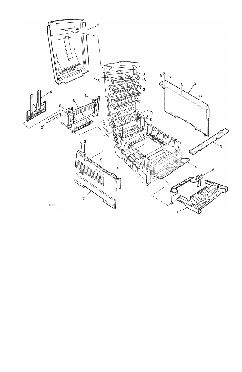
Figure 1 Cabinet FRUs
Service Guide
189
Page 4

Table 2 FRU part list of the top cover assembly
Fig 2
parts
Part
number
Name and description
1 802E33490 Top Cover
2 140E45610 Toner Sensor Board
3 - - - - - Toner Sensor Actuator (part of Flag Kit, p.n. 600K88990))
4 056E04120 Control Panel Bezel (English)
056E04660 Control Panel Bezel (Icon)
5 - - - - - Control Panel Tape Harness (part of Harness Kit, p.n. 600K88980)
6 101K42810 Control Panel Assembly
7 - - - - - Top Cover Latch Springs (part of item 10)
8 - - - - - Top Cover Latch (part of item 10)
9 - - - - - Top Cover Handle (part of item 10)
10 600K88450 Top Cover Inner Frame Kit (includes items 7-9, 20, 21)
11 022E24900 Eject Roller
12 130K65650 Stack Full Sensor w/actuator
13 038K13450 Eject Guide Assembly
14 - - - - - LED Harness C (part of Harness Kit, p.n. 600K88980)
15 - - - - - LED Harness M ((part of Harness Kit, p.n. 600K88980)
16 - - - - - LED Harness Y (part of Harness Kit, p.n. 600K88980)
17 - - - - - LED Harness K (part of Harness Kit, p.n. 600K88980)
18 - - - - - LED Assembly Spring (part of Hardware Kit, p.n. 600K89010)
19 107K01920 LED Assembly
20 - - - - - Lower Eject Roller Bracket (part of item 10)
21 - - - - - Upper Eject Roller Bracket (part of item 10)
22 - - - - - 26 Pin LED Connector (part of Harness Kit, p.n. 600K88980)
190
Phaser 1235 Network Color Printer
Page 5
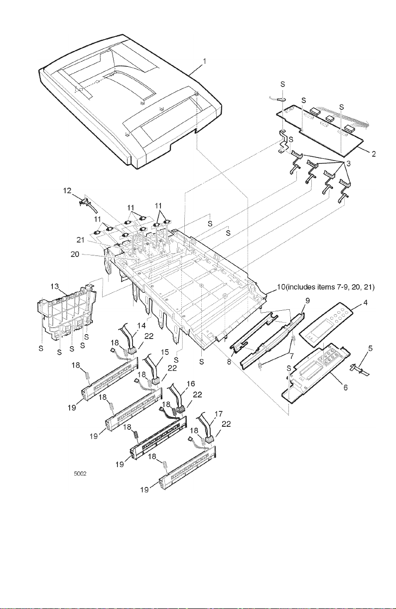
Figure 2 Top cover FRUs
Service Guide
191
Page 6

Table 3 FRU part list of the printer chassis (1 of 2)
Fig 3
parts
1 038K13460 Duplex Guide Assembly
2 022E24940 Fuser Exit Roller
3 009K01960 Right Top Cover Spring Assembly
4 - - - - - Fuser Drive Gear A (part of Gear Kit, p.n. 600K89000)
5 - - - - - Fuser Drive Gear B (part of Gear Kit, p.n. 600K89000)
6 - - - - - Fuser Drive Gear C (part of Gear Kit, p.n. 600K89000)
7 - - - - - Fuser Exit Roller Bushing (Right) (part of Hardware Kit, p.n.
8 115K01970 Drum Contact Assembly
9 115E01970 Fuser Exit Roller Contact
10 121K25800 Duplex Gate Solenoid Assembly
11 022K78610 Registration Roller Assembly A
12 007K11730 Registration Drive Gear A
13 - - - - - Registration Motor Ground Contact
14 127K35200 Registration Motor Assembly
15 121K25810 Registration Clutch
16 - - - - - A Registration Exit Sensor Actuator (part of Flag Kit, p.n. 600K88990)
17 - - - - - A Registration Entrance Sensor Actuator (part of Flag Kit, p.n.
18 600K88480 Entrance Sensor Board w/harness
19 022K78620 Registration Roller Assembly B
20 - - - - - B Registration Entrance Sensor Actuator (part of Flag Kit, p.n.
21 - - - - - Waste Toner Sensor Actuator (part of Flag Kit, p.n. 600K88990)
22 101K42820 Printer Unit Chassis
23 130K65680 Color Registration Sensor Assembly
24 127K35230 Main Cooling Fan
25 - - - - - Fuser Exit Roller Bushing (Left) (part of Hardware Kit, p.n. 600K89010)
26 009K01950 Left Top Cover Spring Assembly
27 - - - - - Fuser Latching Handle Spring (part of Hardware Kit, p.n. 600K89010)
28 003E55690 Fuser Latching Handle (Left)
29 130K65670 Exit Sensor Assembly
30 815E06790 Registration Shutter Plate
31 121K26000 Registration Shutter Solenoid
32 - - - - - Shutter Spring (part of Hardware Kit, p.n. 600K89010)
33 116-0992-00 Low-Voltage Power Supply Fan
S - - - - - Screw (part of Hardware Kit, p.n. 600K89010)
Part
number
Name and description
600K89010)
600K88990)
600K88990)
192
Phaser 1235 Network Color Printer
Page 7
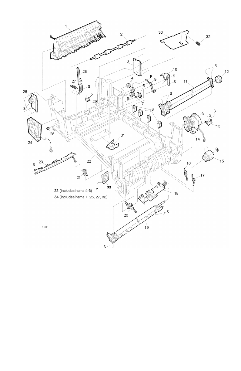
Figure 3 Printer chassis FRUs (1 of 2)
Service Guide
193
Page 8

Table 4 FRU of the printer chassis (2 of 2)
Fig 4
parts
1 127K35180 Main Motor Assembly
2 115K02020 Transfer Contact Assembly
3 118E16970 Power Supply Insulation
4 015K55950 Left Plate Assembly
5 127K35190 Transfer Belt Motor Assembly
6 - - - - - Fuser Latching Handle Spring (part of Hardware Kit, p.n. 600K89010)
7 003E55700 Fuser Latching Handle (Right)
8 127K35170 Main Feeder Drive Motor
9 - - - - - Gear H1(part of Gear Kit, p.n. 600K89000)
10 - - - - - Gear H2 (part of Gear Kit, p.n. 600K89000)
11 - - - - - Lower Plate
12 116-1058-00 High-Voltage Power Supply Fan
S - - - - - Screw (part of Hardware Kit, p.n. 600K89010)
Part
number
Name and description
194
Phaser 1235 Network Color Printer
Page 9

Figure 4 Printer chassis FRUs (2 of 2)
Service Guide
195
Page 10

Table 5 FRU of the paper tray
Fig 5
parts
1 050K50630 Paper Tray Cassette
2 600K89020 Retard Pad and Springs Kit
Part
number
Name and description
196
Phaser 1235 Network Color Printer
Page 11

Figure 5 Paper tray FRUs
Service Guide
197
Page 12

Table 6 FRU of the paper tray guide
Fig 6
parts
1 032K03330 Paper Tray 1 Right Guide Assembly (includes items 2-10, 15, 20)
2 017E09930 Foot
3 - - - - - Paper Tray Lift Arm (Right) (part of item 1 and 18)
4 - - - - - Plastic Roller (part of Hardware Kit, p.n. 600K89010)
5 - - - - - Paper Tray Lift Spring (part of item 1 & part of item 18)
6 120E20420 Paper Size Actuator
7 140E45620 Paper SIze Sensing Board w/Harness
8 - - - - - Paper Tray Lock (part of item 1 & part of item 18)
9 - - - - - Paper Tray Lock Spring (part of item 1 & part of item 18)
10 - - - - - Plastic Slide (part of item 1 and 18)
11 022K78600 Main Feeder Assembly
12 - - - - - Feed Roller (part of Paper Feed Kit, p.n. 600K89320)
13 - - - - - Nudger Roller (part of Paper Feed Kit, p.n. 600K89320)
14 - - - - - Main Feeder Drive Gear (part of Gear Kit, p.n. 600K89000)
15 - - - - - Right Duplex Ground Contact (part of item 1)
16 - - - - - Bottom Plate
17 - - - - - Left Duplex Ground Contact (part of item 18)
18 032K03320 Paper Tray 1 Left Guide Assembly (includes items 2, 4, 5, 8-10, 17, 19)
19 - - - - - Paper Tray Lift Arm (Left) (part of item 18)
20 - - - - - Duplex Connector (part of item 1)
S - - - - - Screw (part of Hardware Kit, p.n. 600K89010)
Part
number
Name and description
198
Phaser 1235 Network Color Printer
Page 13

Figure 6 Paper tray guide FRUs
Service Guide
199
Page 14

Table 7 FRUS of the multi-sheet bypass feeder
Fig 7
parts
1 022K78630 Multi-sheet Bypass Feeder Assembly
2 012E12690 Link
3 007K11740 Multi-sheet Bypass Feeder Drive Gear
4 802K24030 Multi-sheet Bypass Feeder Cover Assembly
5 - - - - - Multi-sheet Bypass OHP Sensor (part of item 1)
6 - - - - - Multi-sheet Bypass Tray Empty Sensor (part of item 1)
S - - - - - Screw (part of Hardware Kit, p.n. 600K89010))
Part
number
Name and description
200
Phaser 1235 Network Color Printer
Page 15

Figure 7 Multi-sheet bypass feeder FRUs
Service Guide
201
Page 16

Table 8 Electrical components FRUs
Fig 8
parts
1 105K25110 Low Voltage Power Supply (115V)
2 105K25120 High Voltage Power Supply
3 - - - - - High Voltage Tape Harness (part Harness Kit, p.n. 600K88980))
4 127K35220 Electrical Chassis Cooling Fan
5 140E45640 Print Engine Controller Board
6 672-1595-00 System Controller Board (Image Processor Board)
7 121K25530 Internal Hard Drive
8 - - - - - Shield Plate
9 - - - - - Right Shield Plate
10 110K13470 Front Cover B Interlock Switch
11
12 110K13450 Top Cover A Interlock Switch
13 162K68220 Paper Tray 2 Connector with Harness
14 098S04423 Token Ring Card
15 537E61970 Print Engine Controller EEPROM
16 156-4811-00
S - - - - - Screw (part of Hardware Kit, p.n. 600K89010)
Part
number
105K25130 Low Voltage Power Supply (230V)
156-4780-10
156-4839-00
Name and description
64-Mbyte RAM DIMM
128-Mbyte RAM DIMM
256-Mbyte RAM DIMM
202
Phaser 1235 Network Color Printer
Page 17

Figure 8 Electrical components FRUs
Service Guide
203
Page 18

Table 9 FRUs of the duplexer unit
Fig 9
parts
1 022K78640 Duplexer Transport Assembly
Part
number
Name and description
204
Phaser 1235 Network Color Printer
Page 19

Figure 9 Duplexer unit
Service Guide
205
Page 20

Table 10 FRUs of the Lower Tray Assembly
Fig 10
parts
Part
number
Name and description
1 140E46240 Feeder Control Board
2 962K00700 Upper Connector w/harness
3 962K00690 Lower Connector w/harness
4 022K79500 Idler Roller Assembly
5 127K40870 Feeder Motor
6 121K26030 Feeder Clutch
7 022K79510 Feeder Drive Assembly
8 017E09930 Foot (4)
9 120E20420 Paper Size Actuator
10 140E45620 Paper Size Sensing Board w/Harness
050K50630 Paper Tray Cassette
022K79600 Lower Tray Assembly (with tray)
206
Phaser 1235 Network Color Printer
Page 21

Figure 10 Lower Tray Assembly FRUs
Service Guide
207
Page 22

Table 11 Hardware kit
Part
number
600K89010 Hardware Kit
- - - - - LED Assembly Spring Kit (2)
- - - - - Plastic Roller (2)
- - - - - Fuser Exit Roller Bushing (L) (1)
- - - - - Fuser Exit Roller Bushing (R) (1)
- - - - - Shutter Spring (1)
- - - - - Fuser Latch Handle Springs (2)
- - - - - Screw T3x8 (10)
- - - - - Screw T3x10 (10)
- - - - - Screw T4x10 (10)
- - - - - Screw M2x8 (10)
- - - - - Screw M3x6 (10)
- - - - - Screw M3x8 (10)
- - - - - Screw M4x8 (10)
- - - - - Screw SP3x10 (10)
Table 12 Gear kit
Name and description
208
Part
number
600K89000 Gear Kit
- - - - - Main Feeder Drive Gear
- - - - - Gear H1
- - - - - Gear H2
- - - - - Fuser Drive Gear (A)
- - - - - Fuser Drive Gear (B)
- - - - - Fuser Drive Gear (C)
Name and description
Phaser 1235 Network Color Printer
Page 23

Table 13 Sensor flag kit
Part
number
600K88990 Flag Kit
- - - - - B Reg Entrance Sensor Actuator
- - - - - A Reg Entrance Sensor Actuator
- - - - - A Reg Exit Sensor Actuator
- - - - - Toner Sensor Actuator
Table 14 Harness kit
Part
number
600K88980 Harness Kit
- - - - - LED Harness M
- - - - - LED Harness C
- - - - - LED Harness Y
- - - - - LED Harness K
- - - - - Control Panel Tape Harness
- - - - - HV Tape Harness
- - - - - 26 pin LED connector
- - - - - Numerous other harnesses (cables) to be added soon.
Name and description
Name and description
Service Guide
209
Page 24

Table 15 Customer replaceable consumables
Part
number
008R12685 Fuser (1235) (110 V)
008R12686 Fuser (1235) (220 V)
006R90293 Standard Toner Cartridge (Black) (1235)
006R90294 Standard Toner Cartridge (Cyan) (1235)
006R90295 Standard Toner Cartridge (Magenta) (1235)
006R90296 Standard Toner Cartridge (Yellow) (1235)
006R90303 Hi Capacity Toner Cartridge (Black) (1235)
006R90304 Hi Capacity Toner Cartridge (Cyan) (1235)
006R90305 Hi Capacity Toner Cartridge (Magenta) (1235)
006R90306 Hi Capacity Toner Cartridge (Yellow) (1235)
013R90132 Imaging Drum (Black) (1235)
013R90133 Imaging Drum (Cyan) (1235)
013R90134 Imaging Drum (Magenta) (1235)
013R90135 Imaging Drum (Yellow) (1235)
016-1934-00 Cyan/Magenta/Yellow Imaging Drum Rainbow Pack (1235)
001R00559 Transfer Belt Unit (1235)
801K01300 Drum/Toner Cartridge Basket
Name and description
210
Phaser 1235 Network Color Printer
 Loading...