

Page 1

T.O.
33K3-4-3210-1
CALIBRATION
DIGITAL
TECHNICAL
MANUAL
PROCEDURE
FOR
SAMPLING
OSCILLOSCOPE
11801B&11801C
(TEKTRONIX)
Distribution
official
document
OH
43056-6116.
Destruction Notice-For
disclosureofthe
Statement-Distribution
useorfor
administrativeoroperational purposes
shallbereferredtoAFMETCAL
contentsorreconstructionofthe
authorizedtoU.S.
Detachment
unclassified, limited
Published
under
Authorityofthe
Government
only, 30
1/MLLW,
documents,
document.
Secretaryofthe
CHANGE
agencies
July
1998.
813
Irving-WickDrW,
destroybyany
Air
1-30
method
Force
and
their
contractors
Other
requests
Suite
that
will
prevent
30
JULY
SEPTEMBER
for
this
4M,
for
Heath,
1998
1999
Page 2
T.O.
33K3-4-3210-1
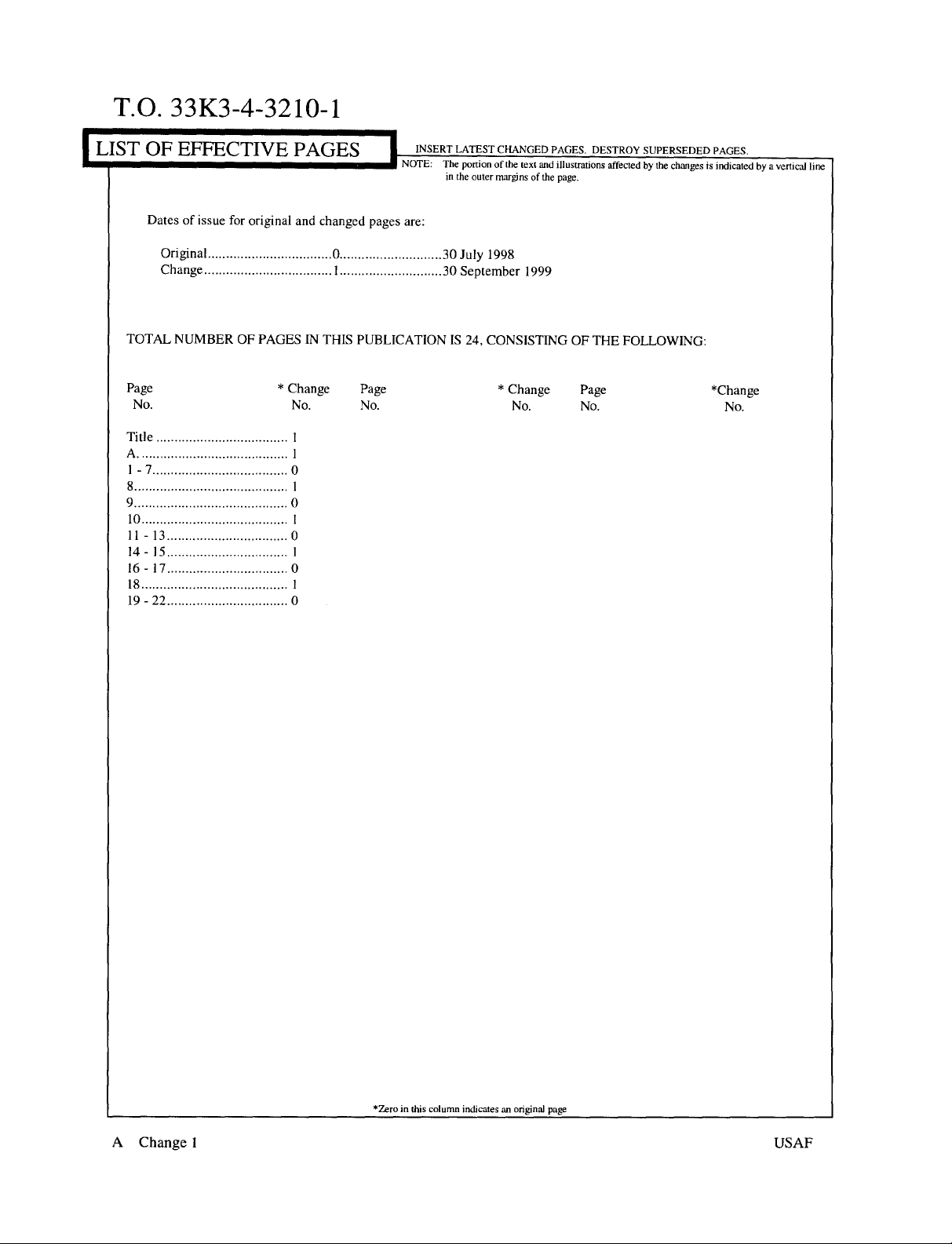
~FE~CTIVEPAGE~I
Datesof
TOTAL NUMBEROFPAGESINTHIS
Page
No.
Title
A
1-7
8
9
10
11-13
14-15
16-17
18
19-22
Original
Change
issue
for
original and changed
0
I
*
Change
No. No.
I
1
0
0
I
0
0
0
INSERT LATEST
NOTE:
The
portionofthetext
in
the
outer
pages
are:
30
July
30
September
PUBLICATIONIS24,
Page
CHANGED
marginsofthe
PAGES.
and
illustrations
page.
DESTROY
1998
1999
CONSISTINGOFTHE
*
Change
Page
No. No.
SUPERSEDED
affectedbythe
FOLLOWING:
PAGES.
changesisindicatedbya
*change
No.
vertical
line
A
Change
uzero in
this column
I
indicatesanoriginal
page
USAF
Page 3

T.O.
33K3-4-3210-1
DIGITAL SAMPLING
118MB&11801C
1
CALIBRATION
Test
Instrument
DESCRIPTION:
(TI)
Performance
Characteristics Specifications
Vertical
Offset
Sweep
Gain
Rate
Range:
Accuracy:
Range:
Accuracy:
Range:Ips/divto5
Accuracy:
0.05%@2
0.08%@1
0.8%@100
2.5%@10
10%®I
2 to
±1.0%offull
±2
Volts
±2
ns/div;
ns/div;
ps/div;
ps/div
OSCILLOSCOPE
(TEKTRONIX)
Table
1.
200mV/div
scale
mY
ms/div
ps/div;
Test
Method
Checked
voltages
Checked
voltages
Known
andmeasured
with
with
signalsapplied
standard
standard
with
the
TI
Trigger
Internal
Sensitivity
Direct
Prescaler
Clock
Range:30kHzto3
Accuracy:
Range:
Accuracy:
600mV
2 V
Range:
Accuracy:
Rise
Frequency,
Duty
AC
Coupled,
2 to100Hz
AC
Coupled:
p-p, 2 to8GHz;
p-p.8to10GHz
100
kHz
Time,
2.5
ns;
±3%;
Cycle,
50%
±3%
GHz
100mVp-p
Applyminimum
and
checkforstable
Apply
minimum
and
checkforstable
Measured
with
signals
signals
the
display
display
TI
I
Page 4

T.O.
33K3-4-3210-l
Test
Instrument
(TI)
Performance
Characteristics Specifications
Table1.(Cont.)
Test
Method
Calibrator Range:
Accuracy:Vp-p.
Rise
Time,
2
EQUIPMENT
REQUIREMENTS:
Minimum
2.1
CALIBRATION
HEAD
Noun
Specifications
Range:10MHzto10
50f2
Accuracy:
2,2 VOLTAGE
CALIBRATOR
2.3
SAMPLING
Range:-2to
Accuracy:
Range:10MHzto10
HEAD
Accuracy:
2.4
POWER
DIVIDER
Range:55MHzto1.1
6dBload isolation
250mVp-p
±10%;
250
ps
Use
±0.5
~2
+2VDC
±0.025%
±2.5%
(20%to80%)
GHz;
GHz
0Hz,
Calibration
Equipment
Tektronix
067-1413-00
Fluke
5700A
w/OptO3
Tektronix
SD-24
Tektronix
015-1014-00
Measured
with
SubItem
the
TI
2.5
SYNTHESIZED
SWEEPER
2.6
POWER
POWERSENSOR
2.7
SMAT
CONNECTOR
2.8
ATTENUATOR
(2
each)
2
METER!
Accuracy:
Range:10MHzto10
0
to I V
Accuracy:
Range:
Accuracy:
8to10
Range:
Accuracy:
Range:
Accuracy:
N/A
rms
(+13.01
±0.0125%
2 to100Hz
2 to80Hz,
GHz,
5.8%
N/A
N/A
2X
N/A
0Hz;
dBm)
±5.4%;
Hewlett-Packard
8340B
Hewlett-Packard
436A
w/8485A
Tektronix
015-1016-00
Tektronix
015-1001-00
Page 5

TO.
33K3-4-3210-1
Noun
2.9RFCable
2.10
LEVELED
SINE
WA
GENERATOR
2.11
ATTENUATOR
3
PRELIMINARY
3.1
Review
and
VE
OPERATIONS:
become
Unless
ensure
or
turned
the
proper
familiar
otherwise
that
all
off,
position
Minimum
Specifications
Range:12in,
Accuracy:
Range:
800
Accuracy:
Range:
20 dB
Accuracy:
with
entire
designated,
test
equipment
where
applicable.
before
Use
SMA
connectors
N/A
MHzat1Vp-p
±5%
N/A
procedurebeforebeginning
Ii
and
priortobeginning
voltage
Ensure
making
WARNING
and/or
that
connectionsorapplying
ii
currentoutputs
all
equipment
Calibration
Equipment
Tektronix
174-
1364-00
Tektronix
SG504
Tektronix
011-0086-00
Calibration
theCalibration
are
switches
power.
Process.
Process,
settozero
are
set
SubItem
(0)
to
3.2
ConnectTIand
minute
warm-up
3.3
Each
time
microprocessor
completionofthe
The
input
diodes
usedinthe
from
overdrive
voltage
theTIonly inastatic-controlled
test
equipmenttothe
period.
Never
installorremoveasampling
outside
voltages,
the
range
sampling
and
from
printedonthe
appropriate
theONposition.
theTION/STANDBYswitchisset
subsystems,
Power-On
followedbySelf-Test
diagnosticsissignified
~EAUTION
heads
electrostatic
frontofthe
area.
power source,
I
CAUTION
head
with
to ON,
theTIperforms
diagnosticsonmost
when
theTIreturnstonormal
I
are
very
discharge.
I
theTION/STANDBY
susceptibletodamage
Never
apply
sampling
set
POWERswitches
allofits
Kernel
head.
diagnosticsonits
main
operation.
a
Operate
switch
circuits.
ON
and
allowa30
in
Successful
3
Page 6

TO.
33K3-4-3210-1
NOTE
3.4
Throughout
and
all
pop-up
4
CALIBRATION
4.1
VERTICAL
4.1.1
SetTION/STANDBY
Frontpanelcontrols
however,
failure
displays
this
possibletoexit
If
effectatthe
the
menu
any
occurs,
the
Extended
menu.
Note
theTIpassesPower-On
lastpower-off
Calibration
items
will be in
PROCESS:
Unless
otherwise
action
whenever
GAIN
CALIBRATION:
switchtoSTANDBY
areactive
disturbanceofthese
theTIautomatically
Diagnostics
thatifthe
the
menu.
Procedure,
Italics.
specified,
the
test
during
controls
menu.
diagnostics
diagnostics,
are
restored.
all
hard
keys
verify
the
requirementisnot
and
the
Self-Test
causesatest
enters
the
Touch
detectafatal
NOTE
the
front
will be in
NOTE
resultsofeach
met,
install
the
diagnostic
Extended
the
panel
all
before
Calibration
sequence;
failure.Ifsuch
Diagnostics
Exit label
fault,itmay
settingsthat
CAPS,
main
test
and
take
proceeding.
Head
a
mode
and
twicetoremove
not
be
were
in
menu
items
corrective
into
theTICH
will be in Bold,
l/CH2slot.
4.1.2
SetTION/STANDBY
4.1.3
Set
the
Calibrator
4.1.4
OPRJSTBYtoOPR.
InitializeTI
switch
If
poweringupfromacold start,
Calibration
exit
the
subsequent
steps.
Voltage
mainframeasfollows:
Head.
diagnosticsbytouchingthe
time
base
Calibratorto0Vand
UTILITY Press
Initialize
Initialize
to ON.
the
The
report
will
calibration
(main
(verification
failure
connecttothe
menu)
pop-up
NOTE
diagnostics
indicateaTime
(E)
Exit
notice
menu) Touch
selector
and
DIRECT
will
reportanerror
Base
error. To
twice.
continue
InputoftheCalibration
Then,
with
Touch
using
clear
ignore
the
the
this,
the
following
Head.
Set
the
Voltage
4
Page 7
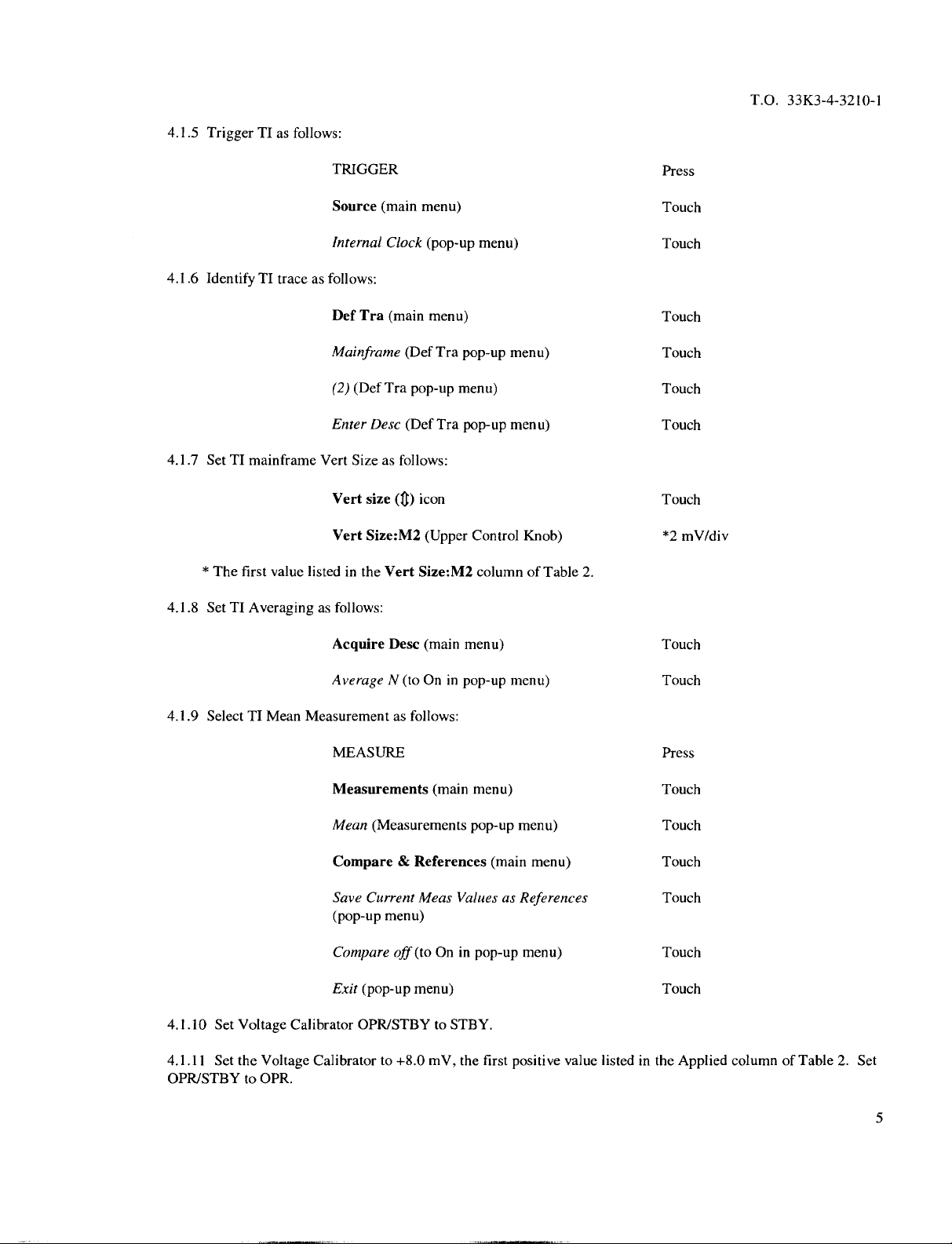
4.1.5
TriggerTIas follows:
T.O.
33K3-4-32l0-l
4.1.6
IdentifyTItrace
4.1.7
SetTImainframe
*
The
4.1.8
Set
as follows:
Vert
first
valuelistedinthe
TI
Averagingasfollows:
TRIGGER
Source
Internal
Def
Mainframe
(2)
Enter
Vert
Vert
(main
Clock
Tra
(main
(DefTra
Desc(Def
Sizeasfollows:
size
Size:M2
Vert
menu) Touch
(pop-up
menu) Touch
(Def
pop-up
(~)
icon
(UpperControl
Size:M2
menu) Touch
Tra
pop-up
menu) Touch
Tra
menu) Touch
pop-up
menu)
Knob)
columnofTable
2.
Press
Touch
Touch
*2
mV/div
4.1.9
SelectTIMean
4.1.10 Set
4.1.11
OPRJSTBYtoOPR.
Voltage
Set the
Voltage
Acquire
Average
Measurementasfollows:
Desc
N
(toOnin
MEASURE
Measurements
Mean
(Measurementspop-up
Compare&References
Save
Current
(pop-up
Compare
Exit
Calibrator
Calibratorto+8.0
menu)
off
(toOnin
(pop-up
OPRISTBYtoSTBY.
menu)
(main
menu) Touch
pop-up
(main
menu) Touch
Meas
ValuesasReferences
pop-up
mV,
the
first
menu) Touch
menu)
(main
menu) Touch
menu) Touch
positive
value listedinthe
Press
Touch
Touch
Touch
Applied
columnofTable2.Set
5
Page 8

T.O.
33K3-4-32l0-l
4.1.12 Touch
4.1.13
in
the
Limits
4.1.14
4.1.15 Set
OPRJSTBYtoOPR.
4.1.16
in
the
Limits
4.1.17
4.1.18
Table
2.
TI
Wait
for
averagingtocomplete.
columnofTable
Set
Voltage
the
Voltage
Wait
for
averagingtocomplete.
columnofTable
Set
Voltage
Repeat
steps
Remove/Cir
Averaging
return
Main
Trace
2.
will
when
averagingiscomplete.
Size
setting
Calibrator
Calibrator
4.1.7
OPRJSTBYtoSTBY.
Calibratorto-8.0
2.
OPRJSTBYtoSTBY.
and
4.1.11
(main menu),
TheTIA
complete
two
notches higher
mV,
TheTIA
through
then
Mean
fasterifyou
the
first
Mean
4.1.17
ClearTrace
indication
NOTE
exit
the
measurement menu
Alternatively,use
than
the
default
negative
for
Table
valueinthe
indication
the
remaining
2.
(pop-up
mustbewithin
menu).
thecorresponding
and
the
dialtomove
setting.
Applied
mustbewithin the
Vert
Size:M2
columnofTable2.Set
then
the
corresponding
and
Applied
values
values
values
listed
listed
listed
in
___________
Vert
2
mV/div
5
mV/div
10
mV/div
20
mV/div
50
mV/div
100
Size:M2
mV/div
Applied
+8.0
mV
-8.0
mV
-20.0
mV
+20.0
mV
+40.0
mV
-40.0
mV
-80.0
mV
+80.0
mV
+200mV
-200
mV
-400
mV
+400mV
Limits
+7.8to+8.2
-8.2to-7.8
-20.5 to
+19.5to+20.5
+39.0to+41.0
-41.0to-39.0
-82.0to-78.0
+78.0to+82.0
mV
mV
-19.5
+l95to+205mV
-205to-195
-410to-390
mV
mV
+390to+4lOmV
mV
mV
mV
mV
mV
mV
6
Page 9

Vert
200
Size:M2
mV/div
Table2.(Cont.)
Applied
+800mV
-800mV
NOTE
T.O. 33K3-4-3210-1
Limits
+780to+820mV
-820
to_-780_mV
4.1.19
InitializeTImainframe
4.1.20
TriggerTIas
4.1.21
Define
the
Uptonow,
mainframe
verify
2,
using
Calibration
you
acquisition
the
vertical
trace2.(Do
Head
UTILITY
Initialize
Initialize
follows:
TRIGGER Press
Source
Internal
first
traceasfollows:
TI
Def
have
been
measurement
accuracy
not
DIRECT
as follows:
(main
(verification
(main
menu) Touch
Clock
(pop-up
Tra
(main
menu) Touch
working with
throughinternal
removeVoltage
Input).
trace
1
(Channel 2),
channel1.Use
acquisition
Calibrator
the
following
measurement
connection
and
Press
internal
from
menu) Touch
pop-up
menu) Touch
menu)
Touch
steps to
channel
Note
that
TraceIhas
Mainframe
(1)
(DefTra
Enter
Desc(Def
been
selectedatthe
(Def
pop-up
Tra
pop-up
menu) Touch
menu) Touch
Tra
pop-up
menu) Touch
baseoftheTIscreen
(just
aboveMlMain).
7
Page 10

TO.
33K3-4-32l0-l
4.1.22
Define
the
secondTItraceasfollows:
Def
Tra
(main menu)
Touch
Note
•
4.1.23 Repeat
4.1.24
Set TI
4.1.25
Remove
Voltage
4.1.26 Repeat
4.1.27 Repeat
4.1.28 Repeat
4.2
OFFSET
that
Trace2has
steps
Mainframe
(2) (Def
Enter
been selectedatthe
4.1.3
and
4.1.7
(Def
Tra
pop-up menu) Touch
Desc
(DefTra
through
ON/STANDBYtoSTANDBY.
the
Calibration
Head from
Calibrator connectedtoCalibration
steps
4.1.2
through
step
4.1.25
except
step
4.1.25
except
CALIBRATION:
This
Offset
Calibration.
have
activated
continue
with
test
The
power-up
step
4.1.24.
move
fromCH3/CH4slot toCH5/CH6slot.
move
fromCH5/CH6slot toCH7/CH
uses
the
Calibration
4.2.1.
Tra
pop-up menu)
pop-up menu) Touch
baseoftheTIscreen
(just
4.1.18.
theTICH
ItCH2slot
and install into
Head.
NOTE
samesetuppreliminariesasthe
Head/Time
diagnostics.Ifso,
Base
exit
error
will
diagnostics
Touch
above
8 slot.
Vertical
only
reappear
and,ineither
M2Main).
the
TI CH
Repeat
Repeat
Gain
3/CH4slot.
step
4.1.26.
step
4.1.26
if
you
case,
Leave
4.2.1 SetTION/STANDBY
into
4.2.2
4.2.3
4.2.4
8
theTICH
Set
Set
InitializeTI
Change
ItCH
2 slot.
TI
ON/STANDBY
Voltage
Calibrator
mainframeasfollows:
1
switchtoSTANDBY,
Leave
Voltage
switch
to ON.
to 0
Vand
set
UTILITY
Initialize
Initialize
(main
(verification
remove
Calibrator connectedtoCalibration
OPR/STBYtoOPR.
menu) Touch
pop-up
Calibration
menu) Touch
Head
fromTICH
Head.
Press
7/CH8slot
and
install
Page 11
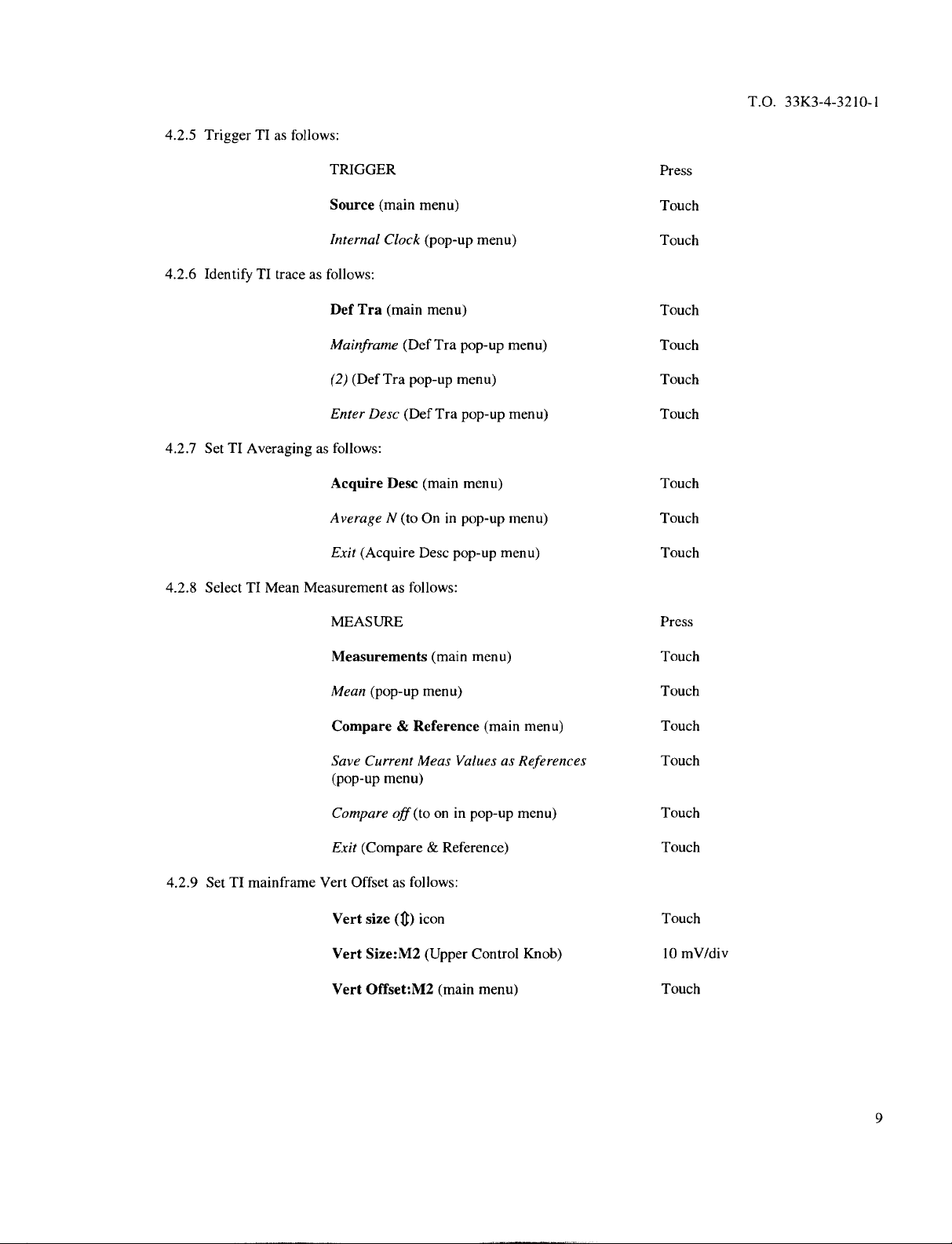
4.2.5
TriggerTIas
follows:
TRIGGER Press
T.O.
33K3-4-32
10-1
Source
Internal
4.2.6
IdentifyTItraceasfollows:
Def
Tra
Mainframe
(2)
(Def
Enter
4.2.7
SetTIAveragingasfollows:
Acquire
AverageN(toOnin
Exit
(Acquire
4.2.8
SelectTIMeanMeasurementasfollows:
MEASURE
Measurements
(main
menu) Touch
Clock
(main menu)
(Def
Tra
pop-up
Desc
(DefTra
Desc
Desc
(pop-up
(main
menu) Touch
Tra
pop-up
menu) Touch
menu) Touch
pop-up
pop-up
(main
menu)
menu) Touch
pop-up
menu) Touch
menu)
menu) Touch
Touch
Touch
Touch
Press
4.2.9
SetTImainframe
Mean
(pop-up
menu) Touch
Compare&Reference
Save
Current
(pop-up
Compare
Exit
(Compare&Reference)
Vert
Offsetasfollows:
Vert
size
Vert
Size:M2
Vert
Offset:M2
menu)
off
(~)
Meas
(to
on in
icon
(Upper
(main menu) Touch
(main
menu) Touch
ValuesasReferences
pop-up
Control
menu) Touch
Knob)
Touch
Touch
Touch
10
mV/div
9
Page 12

T.O.
33K3-4-3210-l
Verify
the
valuekeyedinhas
Keyin(pop-updisplay) 400 mV
Enter
(pop-up
display)
enteredinto
theTIdisplay
below
Vert
Touch
Offset:M2.
NOTE
4.2.10
OPR.
4.2.11
4.2.12 Verify
4.2.13 Set
14.2.14
the
applied
Use
CHS
values.
Set
the
Voltage
Wait
for
theAMean valueiswithin
Voltage
Repeat
steps 4.2.3
values
Calibratortothe
the
averagingtocomplete.
Calibrator
into
theTIpop-updisplayinstep
keyonpop-updisplaytochange
first
value listedinthe
thecorresponding
OPRJSTBYtoSTBY.
through
4.2.13
for
the
remaining
4.2.9.
Table
signofentered
Applied
values
listedinthe
values
listedinthe
3.
voltage
columnofTable
fornegative
Limits
Applied
Applied Limits
400mV
1V
2V
-400
mV
398
0.998tol.002V
l.998to2.002V
-402to-398
3. Set
OPRJSTBY
columnofTable
columnofTable3.Key
to4O2mV
mV
to
3.
4.2.15
4.2.16
connectedtoCalibration
4.2.17
14.2.18
4.2.19 Repeat
4.2.20
4.2.21
theTI.
10
SetTION/STANDBYtoSTANDBY.
Remove
SetTION/STANDBY
Repeat
Repeat
Set
Change
Calibration
steps
steps
steps
Voltage
1
-l
-2 V
Head.
4.2.3
through
4.2.15
4.2.15
Calibrator
V
Head
from
CH
to ON.
4.2.14.
through
through
4.2.18
except
4.2.18except
OPRJSTBYtoSTBY
l/CH
2 slot
move
move
and
and
installinCH
Calibration
Calibration
disconnect
-1.002to-0.998
-2.002to-1.998
3/CH
4 slot.
Leave
Head
from
CH
3tCH
Head
fromCH5tCH6slot toCH7/CH8slot.
the
test
setup.
Remove
V
V
VoltageCalibrator
4 slot toCH5/CH
Calibration
Head
6 slot.
from
Page 13

4.3
SWEEP
4.3.1
SetTION/STANDBY
4.3.2
Connect
RATE
CALIBRATION:
switchtoSTANDBY
equipmentasshowninFigure1using
CHtSAMPLING
HEAD
and
Figure
install
50 ~
the
coaxial
1.
Sampling
cables.
Head
into
T.O.
theTICH
33K3-4-3210-l
itCH
2 slot.
4.3.3
Set
TI
ON/STANDBY
4.3.4
InitializeTI
4.3.5
Set
theTIhorizontalrecordlengthasfollows:
4.3.6
IdentifyTItraceasfollows:
switchtoON.
mainframeasfollows:
UTILITY Press
Initialize
Initialize (verification
Horizontal
Main
Main
Def
Mainframe
(1)
(main
Record
Record
Tra
(main menu) Touch
(Def
(Def
Tra
menu) Touch
pop-up
menu) Touch
Desc
(main
menu) Touch
Length (pop-up
Len
(Upper
Tra
pop-up
pop-up
menu) Touch
menu) Touch
Control
Knob)
menu) Touch
1024
Enter
Desc
(DefTra
pop-up
menu) Touch
11
Page 14

T.O.
33K3-4-3210-l
4.3.7
EngageTIhigh
precision
calibration
mode
as follows:
4.3.8
4.3.9
ON/OFF
4.3.10
SetTISweep
Set
the
to ON.
TurnTImainframe
Rateasfollows:
Synthesized
Verify
select
UTILITY
PagetoEnhanced
Time Base
High
Prec
(pop-up
Exit
(pop-up
Horizontal
Main
Size
Sweeper
that
channel
frequencyto55MHz
selected
(1) by
averaging
Press
Accuracy
Cal
Mode
menu) Touch
menu) Touch
(~)
icon
(Upper
Control
(main menu) Touch
(main menu) Touch
Touch
Knob)
and
the
amplitude
2
to+13.01
NOTE
Sampling
pressing
on as
Head
select
follows:
channel
button.
(1)
indicatorisflashing.Ifnot,
ns/div
dBm
(1.0Vrms)
and
set
RF
4.3.11
Measure
Set
Main
horizontally
the
display
period
withTIas
WAVEFORM
Acquire
AverageN(toOnin
Exit
Pos control
MEASURE
Measurements
Period
PeaktoPeak
Exit
Desc
(pop-up
centeredonthe
mustbea
Menu
menu) Touch
(Lower
full cycle.
follows:
(pop-up
(pop-up
(pop-up
(main menu) Touch
(main
menu) Touch
Press
pop-up
menu) Touch
NOTE
Control
screen.Toensure
menu) Touch
Knob)sothe
menu) Touch
menu) Touch
displayed
accurate
period
sinewave
measurement,
Press
is
12
Page 15
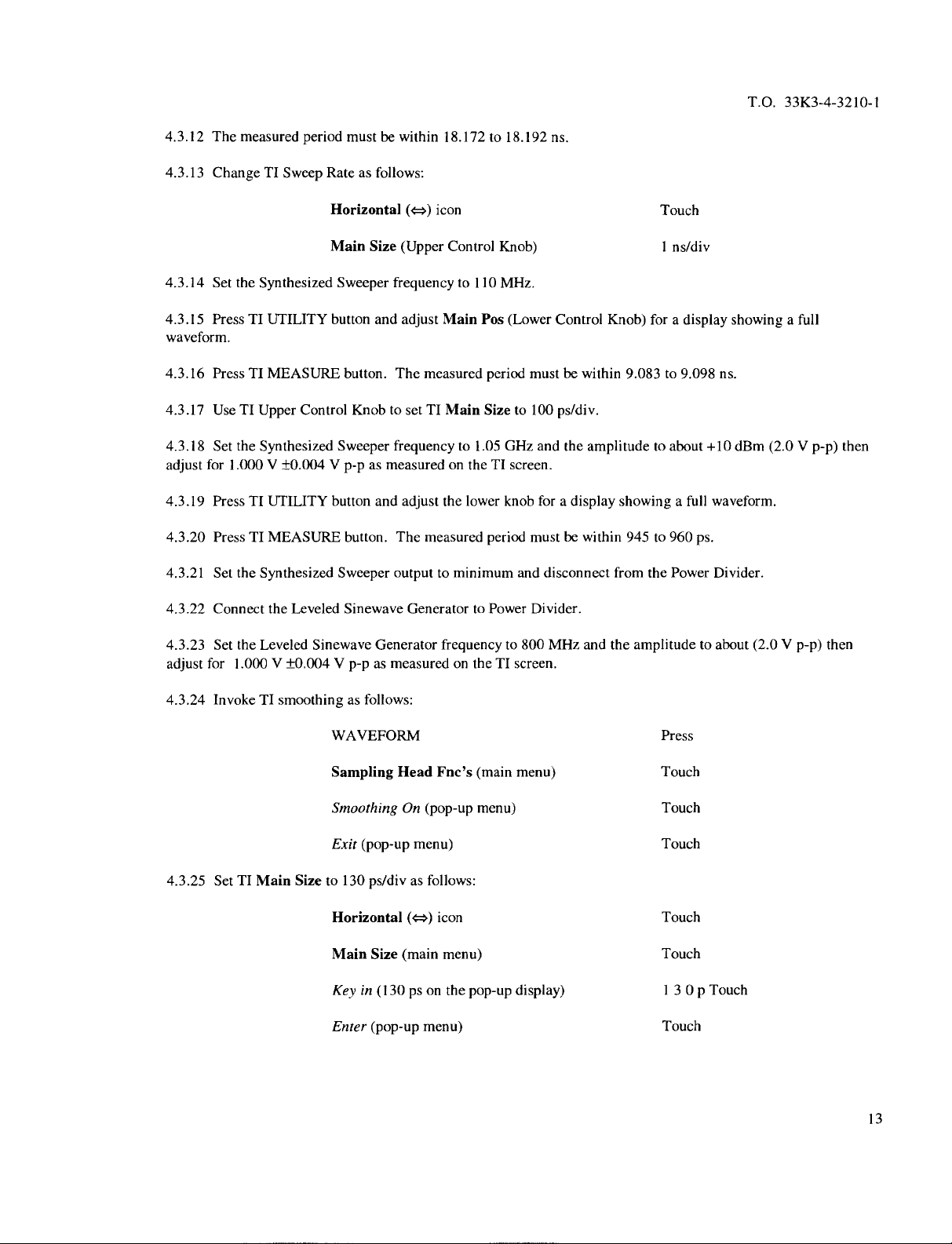
4.3.12
4.3.13
The
measuredperiod
ChangeTISweep
mustbewithin 18.172to18.192
Rateasfollows:
ns.
TO.
33K3-4-3210-1
4.3.14 Set
4.3.15
PressTIUTILITY
waveform.
4.3.16
Press
4.3.17
UseTIUpper
4.3.18 Set
adjust
for 1.000 V
4.3.19
PressTIUTILITY
4.3.20
PressTIMEASURE
4.3.21
Set
4.3.22
Connectthe
4.3.23 Set
adjust
for 1.000 V
the
Synthesized
TI
MEASURE
the
Synthesized
the
Synthesized
the
Leveled
Control
±0.004
Leveled
Sinewave
±0.004
Horizontal
Main
Sweeper
button
button.
Knobtoset
Sweeper
V
p-pasmeasuredontheTIscreen.
button
button.
Sweeper
Sinewave
V
p-pasmeasuredontheTIscreen.
(~=~)
icon
Size
(Upper
frequency
and
adjust
Main Pos
The
measuredperiod
TI
Main
frequency
and
adjustthe
The
measuredperiod
outputtominimum
GeneratortoPower
Generator
frequencyto800
Control
to 110
to 1.05
lower
Knob)
MHz.
Size
0Hz
knob foradisplay
(Lower
Control
mustbewithin
to 100
ps/div.
and
mustbewithin
and
disconnect
Divider.
MHz
the
Knob)
amplitude
showingafull
from
and
the
Touch
1
ns/div
foradisplay
9.083to9.098
to
about
945 to
960
the
Power
amplitudetoabout
ns.
+10
waveform.
ps.
Divider.
showingafull
dBm
(2.0Vp-p)
(2.0Vp-p)
then
then
4.3.24 InvokeTIsmoothingasfollows:
WAVEFORM
4.3.25
SetTIMain
Size
Sampling
Smoothing
Exit
to 130
Head
(pop-up
ps/divasfollows:
Horizontal
Main
Size
Keyin(130
Enter
(pop-up
Press
Fnc’s
(main menu) Touch
On
(pop-up
menu) Touch
menu) Touch
(~)
icon
(main menu)
ps on
the
pop-up
display)
menu) Touch
Touch
Touch
13Op
Touch
13
Page 16
TO.
33K3-4-3210-1
4.3.26
Set TI
Main
Pos to 55 ns as
Main
Pos
follows:
(main
menu) Touch
4.3.27
Set
center
graticule.
4.3.28 Set
horizontal
4.3.29 Touch
4.3.30 Touch
center:
Keyin(55
Enter
(pop-up
To
precisely
change
and
eitherchoosing
the
Main
Pos
theTIhorizontalreference
center
the
resolutionofthe
control
(Lower
WAVEFORM
Horizontal
Center
(pop-up
theTIVertical
theTIHorizontal
(~)
icon
(~t=~)
ns on
the
pop-updisplay)
menu) Touch
NOTE
the
waveformontheTIdisplay,itmaybenecessary
Main
Pos
control.
course,
medium,
Control
pointtoCenterasfollows,sothat
Desc
(main
menu) Touch
and
adjustthe
icon
and
or
Knob)sothat
menu) Touch
Upper
adjust
the
fine.
Control
Upper
Do
thisbytouching
Then
touch
the
zero
Knobtoset
Control
exit.
crossingofthe
the
waveform
Knobtoset
55n
Press
the
Main
waveform
will be
Vert
the
Main
to
Pos
Size
occursonthe
expanded
to 50
mV.
Sizeto10
about
ps/div.
the
4.3.31Touch
-260.5to-248.1
4.3.32 Touch
4.3.33 SetTIMain
4.3.34
4.3.35 Set
center
graticule.
14
Change
Adjust
the
theTICursors
TI
TI
Main
1
icon
and
mVor+248.1to+260.5
Exit
(main
menu).
Size
to 130
ps/divbyrepeating
Main
Pos
to 55 ns by
Pos
control
(Lower
read
theAvlocatedinthe
mV.
step
repeating
Control
step
Knob)sothat
4.3.25.
4.3.26.
the
main
zero
menu.
TheAvindication
crossingof
the
waveform
mustbewithin
occursonthe
Page 17

4.3.36
horizontal
Set
theTIhorizontal
center:
reference
pointtoCenterasfollows,sothat
the
waveform
will be
T.O.
expanded
33K3-4-3210-1
about
the
4.3.37 Touch
4.3.38 Touch
4.3.39 Touch
-28.3to-23.1
4.3.40 TouchTIExit
4.3.41
4.4
TRIGGER
4.4.1
Connect
theTIVertical
the
TI
theTICursors
mYor+23.1to+28.3
Set
the
Leveled
SENSITIVITY
equipmentasshowninFigure2using
WAVEFORM
Horizontal
Center
(~)
Horizontal
icon
(main
menu).
Sinewave
Desc
(main
(pop-up
icon
(~)
Generator
menu) Touch
and
adjusttheupper
icon
and
adjustthe upper
and
read
theAv
mV.
outputtominimumand
CALIBRATION:
CH
1
SAMPLING
HEAD
Press
menu) Touch
knob
the
set
the
Vert
Sizeto5
knob
the
set
the
Main
locatedinthe
50 Q
coaxial
main
disconnect
cables.
menu.
TheAvindication
the
test
Size
set
mV.
to
up.
1
ps/div.
mustbewithin
Figure
2.
Change
1
15
Page 18
T.O.
33K3-4-3210-l
4.4.2
InitializeTI
mainframeasfollows:
4.4.3
Set
4.4.4 Press
4.4.5
Makethe
the
Synthesized
the
Sampling
followingTIselections:
UTILITY
Initialize
Initialize
Sweeper
Head
AUTOSET
Slightly
if
necessary
MEASURE
MEASUREMENT
Peak-Peak
WAVEFORM
Sampling
(main
(verification
frequencyto300
ChannelIbutton.
adjust
(pop-up
Head
Press
menu) Touch
pop-up
menu) Touch
MHz
and
the
amplitudeto-4.0
Press
the
Trigger
(main
Fnc’s
Level
(TRIGGER
menu) Touch
menu) Touch
(main
menu) Touch
main
menu)
Press
Press
dBm
(400
mV
p-p).
4.4.6
TheTImusthaveastable
4.4.7
Set
the
Synthesized
4.4.8
Repeat
steps
4.4.9
Set
the
Synthesized
4.4.10
Repeat
steps
4.4.11
Set
the
Synthesized
4.4.12
appropriate
Standardize
setting
Smoothing(toOnin
Exit
Sweeper
4.4.5
and
4.4.6.
Sweeper
4.4.5
and
Sweeper
and
zero
the
for each
frequency.
(pop-up
4.4.6.
menu) Touch
signal.
frequencyto1
frequencyto3
outputtominimum
Power
Meter
pop-up
GHz
0Hz
andPower
menu) Touch
and
the
and
the
and
disconnect
Sensor.
amplitudeto-4.0
amplitudeto-4.0
the
Set
the
test
Power
dBm
dBm
set
Meter
(400
(400
up.
CalFactor
mY
mV
p-p).
p-p).
dialtothe
16
Page 19

4.4.13
Connect
equipmentasshowninFigure
lI
CH1SAMPLING
3.
HEAD
T.O.
33K3-4-3210-1
4.4.14
4.4.15
4.4.16
-0.46
4.4.17
4.4.18
InitializeTImainframeasfollows:
UTILITY
Initialize
Press
the
Set
the
dBm (600
Disconnect
Makethe
Initialize
Sampling
Synthesized
mV
the
Head
Sweeper
p-p).
cable
followingTIselections:
Def
(verification
ChannelIbutton.
from
the
Tra
(main menu) Touch
Mainframe
(1)
(Def
Tra
TRIGGER
Figure
3.
Press
(main menu) Touch
pop-up
menu) Touch
frequency
PowerSensorand
(Def
Tra
pop-up
to 2
0Hz
and
adjust
the
amplitude
until
connecttotheTIPRESCALER
pop-up
menu) Touch
menu) Touch
Press
the
Power
TRIGGER
Meterindicates
INPUT.
Source
(main
menu)
Touch
17
Page 20
TO.
33K3-4-3210-I
4.4.19
4.4.20
4.4.21
TurnTI
TheTImust
Repeat
averaging
steps
External
Exit
(Source
Horizontal
Main
Vertical
Vert
Size
on as
follows:
WAVEFORM
Acquire
AverageN(toOnin
Exit
(pop-up
haveastable
4.4.12
through
Prescaler
Size
(Upper
(~)
(UpperControl
Desc
signal.
4.4.20.Instep
(Sourcepop-up
pop-up
menu) Touch
(c=~)
icon
Control
icon
(main
menu) Touch
Knob)
Knob)
menu) Touch
pop-up
4.4.16
menu) Touch
menu) Touch
set
the
Synthesized
Touch
200
Touch
10
mV/div
Press
Sweeper
ps/div
frequency
to 8
GHz
and
I
adjustthe
4.4.22 Repeat
adjust
50
4.4.23.
4.5
4.5.1
4.5.2
4.5.3
amplitude
ps/div.
the
amplitude
mV/div.
Set
INTERNALCLOCK
Connect
InitializeTI
Trigger
until
steps
4.4.12
until
the
Synthesized
the
INTERNAL
mainframeasfollows:
TI as
follows:
the
Power
Meterindicates
through
the
CALIBRATION:
UTILITY
Initialize
Initialize
TRIGGER Press
Source
Power
Sweeper
CLOCK
4.4.20.Instep
Meter
indicates10dBm(2V
outputtominimum
OUTPUTtothe
(main
menu) Touch
(verification
(main
menu)
-0.46
4.4.16
pop-up
dBm (600
set
and
disconnect
Sampling
menu) Touch
mV
the
Synthesized
p-p).Instep
HeadCH1
p-p).
the
In step
Sweeper
4.4.18
test
input.
Press
Internal
set
4.4.18
set
frequencyto10
set
the
Vert
up.
Clock
the
Size
Main
0Hz
to
Size
and
to50
18
Change
1
Page 21

4.5.4
PressTIAUTOSET.
4.5.5
Verify
Verify
channel
rise
timeasfollows:
the
(1) by
Sampling
pressing
Head
channel
select
button.
NOTE
(1)
indicatorisflashing.Ifnot,
select
T.O.
33K3-4-3210-l
4.5.6
4.5.7
4.5.8
4.5.9
4.5.10
53%.
4.5.11
4.5.12
The
measured
TouchTIExit
Touch
the
Horizontal
Verify
the
Internal
The
frequency
Press
Exit
Disconnect
rise
Menu
indication
Menu
(pop-upmenu).
the
test
MEASURE
Measurements
Rise
(pop-up
time
mustbe2.5
(pop-upmenu).
(~=~)
and
set
Clockasfollows:
Measurements
Frequency
Dufl’
setup.
(pop-up
Cycle
(pop-up
mustbewithin97to
Press
(main menu) Touch
menu) Touch
ns.
the
Main
Size
to 5 j.ts/div with
(main menu) Touch
menu)
menu) Touch
103
kHz
and
the
the
duty
Upper
Touch
cycle
indication
Control
Knob.
mustbewithin47to
4.6
CALIBRATOR
4.6.1
Connect
4.6.2
InitializeTImainframeasfollows:
4.6.3
TriggerTIas
CALIBRATION:
theTICALIBRATOR
follows:
UTILITY
Initialize
Initialize
TRIGGER
Source
OUTPUTtothe
(main menu) Touch
(verification
(main menu)
pop-up
Sampling
menu) Touch
HeadCH1
input using the12inch
Press
Press
Internal
RF Cable.
Clock
19
Page 22

T.O.
33K3-4-3210-1
4.6.4
PressTIAUTOSET.
4.6.5
Verify
rise
Verify
the
Sampling
channel
time
(1) by
pressing
andpeak-to-peakasfollows:
Headchannel
select
button.
NOTE
(1)
indicatorisflashing.Ifnot,
select
4.6.6
Adjust
4.6.7
The
4.6.8
Set
all
equipment.
4.1
VERTICAL
MEASURE
Measurements
Peak-to-Peak
Rise
(pop-up
Rise
(main
Proximal
Proximalto20%
Rise
Time
indication
all
outputstoOFForminimum.
GAIN
and
mustbe250
CALIBRATION:
Vert
Size:M2
2
mV/div
(main
menu) Touch
(pop-up
menu) Touch
menu) Touch
menu) Touch
(pop-up
menu) Touch
Distalto80%.
ps
and
the
Set
all
CALIBRATION
peak-to-peak
POWER
switchestoSTANDBYorOFF.
PERFORMANCE
mustbewithin
TABLE
Applied
+8.0
mV
Press
225
to 275
Disconnect
Limits
+7.8to+8.2
mV.
mV
and
secure
20
5
mV/div
10
mV/div
20
mV/div
-8.0mV
-20.0
mV
+20.0
+40.0
-40.0
mY
-80.0
mV
+80.0
mV
mV
mV
-8.2 to -7.8
mV
-20.5to-19.5
+
19.5 to
+20.5
+39.0to+41.0
-41.0to-39.0
-82.0to-78.0
+78.0to+82.0
mV
mV
mV
mV
mV
mY
Page 23

TO.
33K3-4-3210-l
4.1
VERTICAL
4.2
OFFSET
GAIN
CALIBRATION:
Vert
Size:M2
50
mV/div
100
mV/div
200mV/div
CALIBRATION:
Applied
400mV
IV
CALIBRATION
(Cont.)
PERFORMANCE
Applied
+200
mV
-200
mV
-400
mV
+400
mY
+800
mV
-800
mY
TABLE
(Cont.)
Limits
398to402mY
0.998
to 1.002
Limits
+195to+205
-205
to -195
-410to-390
+390to+410
+780to+820
-820to-780
V
mV
mV
mV
mV
mV
mV
4.3
SWEEP
RATE
CALIBRATION:
Applied
55MHz@
IlOMHz@
1.1
GHz@0.996
800
MHz@0.996
800
MHz®0.996
2V
-400
-IV
-2 V
l.OVrms
l.OVrms
mV
to 1.004 V
to 1.004 V
to 1.004 V
p-p
p-p
p-p
TI
2
1
100
130
1
Main
ns/div
ns/div
ps/div
ps/div
ps/div
Size
Vert
Main
Size
1.998 to
-402to-398
-1.002to-0.998
-2.002to-1.998
Pos to55ns
to 5
mV
2.002
V
mV
V
V
Limits
18.172to18.192
9.083to9.098
902to916
Av=-260.5to-248.1
or
+248.1to+260.5 mY
Av=-28.3to-23.1
or
+23.1to+28.3
ns
ns
Ps
mY
mV
mV
21
Page 24

T.O.
33K3-4-3210-l
4.4
TRIGGER
4.5
INTERNAL
SENSITIVITY
Function
Direct
Prescaler
CLOCK
CALIBRATION:
Applied
Rise
100
CALIBRATION
CALIBRATION:
Time
kHz
PERFORMANCE
Applied
_______
100mY
100mY
100
600mY
600mY
2.0Vp-p@100Hz
mY
p-p
p-p@1
p-p@3
p-p©2
p-p©8
TABLE
@300MHz
GHz
0Hz
0Hz
GHz
(Cont.)
Limits
2.5
97
ns
to 103
Limits
Stable
Stable
Stable
Stable
Stable
Stable
kHz
display
display
display
display
display
display
50%
4.6
CALIBRATOR CALIBRATION:
Function
Rise
Amplitude
Duty
Time
Cycle
Applied
20 to 80%
250 mY
47to53%
Limits
250
P5
225to275mY
22
 Loading...