

Page 1

TM 11-6625-2978-14
TECHNICAL MANUAL
OPERATOR’S, ORGANIZATIONAL,
DIRECT SUPPORT AND GENERAL SUPPORT
MAINTENANCE MANUAL
FOR
POWER SUPPLY PP-7549/U
(TEKTRONIX MODEL 1106)
(NSN 6130-01-018-1226)
HEADQUARTERS, DEPARTMENT OF THE ARMY
18 FEBRUARY 1982
Page 2

SAFETY STEPS
TO FOLLOW IF SOMEONE
IS THE VICTIM
DO NOT TRY TO PULL OR GRAB THE INDIVIDUAL
IF POSSIBLE, TURN OFF THE ELECTRICAL POWER
IF YOU CANNOT TURN OFF THE ELECTRICAL
POWER, PULL, PUSH, OR LIFT THE PERSON TO
SAFETY USING A WOODEN POLE OR A ROPE OR
SOME OTHER INSULATING MATERIAL
SEND FOR HELP AS SOON AS POSSIBLE
OF ELECTRICAL SHOCK
AFTER THE INJURED PERSON IS FREE OF
CONTACT WITH THE SOURCE OF ELECTRICAL
SHOCK, MOVE THE PERSON A SHORT DISTANCE
AWAY AND IMMEDIATELY START ARTIFICIAL
RESUSCITATION
Page 3

This manual includes copyright material reproduced by permission of the Tektronix, Inc.
ECHNICAL MANUAL
T
DEPARTMENT OF THE ARMY
O. 11-6625-2978-14
N
W
OPERATOR’S, ORGANIZATIONAL, DIRECT SUPPORT,
AND GENERAL SUPPORT MAINTENANCE MANUAL
FOR
POWER SUPPLY PP-7549/U
(TEKTRONIX MODEL 1106)
(NSN 6130-01-018-1226)
REPORTING ERRORS AND RECOMMENDING IMPROVEMENTS
You can help improve this manual. If you find any mistakes or if you know
of a way to improve the procedures, please let us know. Mail your letter, DA
Form 2028 (Recommended Changes to Publications and Blank Forms), or DA
Form 2028-2 located in the back of this manual direct to Commander, US Army Communications-Electronics Command, ATTN: DRSEL-ME-MQ, Fort
Monmouth, NJ 07703.
In either case, a reply will be furnished direct to you.
TM11-6625-2978-14
HEADQUARTERS
ASHINGTON, DC, 18 February 1982
C HAPTER 1.
S
ECTION
C HAPTER 2.
S
ECTION
C HAPTER 3.
S
ECTION
C HAPTER 4.
S
ECTION
C HAPTER 5.
S
ECTION
SECTON
C HAPTER 6.
S
ECTION I.
II.
III.
II.
II.
III.
II.
II.
II.
TABLE OF CONTENTS
Paragraph
INTRODUCTION
I.
General . . . . . . . . . . . . . . . . . . . . . . . . . . . . . . . . . . . . . . . . . . . . . . . . . . . . . . . . . . . . . . . . .
Description and Data . . . . . . . . . . . . . . . . . . . . . . . . . . . . . . . . . . . . . . . . . . . . . . . . . . . . . . . . . . . . . . .
Safety Considerations . . . . . . . . . . . . . . . . . . . . . . . . . . . . . . . . . . . . . . . . . . . . . . . . . . . . . . . . . . . . . .
SERVICE UPON RECEIPT AND INSTALLATION
I.
Service Upon Receipt . . . . . . . . . . . . . . . . . . . . . . . . . . . . . . . . . . . . . . . . . . . . . . . . . . . . . . . . . . . . . . .
Installation . . . . . . . . . . . . . . . . . . . . . . . . . . . . . . . . . . . . . . . . . . . . . . . . . . . . . . . . .
OPERATING INSTRUCTIONS
I.
Function of Controls and Connectors. . . . . . . . . . . . . . . . . . . . . . . . . . . . . . . . . . . . . . . . . . . . . . . . . .
Operation and Inspection . . . . . . . . . . . . . . . . . . . . . . . . . . . . . . . . . . . . . . . . . . . . . . . . . . . . . . . . . . . 3-3
Battery Operation
THEORY OF OPERATION
I.
Circuit Description . . . . . . . . . . . . . . . . . . . . . . . . . . . . . . . . . . . . . . . . . . . . . . . . . . . . . . . . . . . . . . . .
Operation Under Unusual Conditions . . . . . . . . . . . . . . . . . . . . . . . . . . . . . . . . . . . . . . . . . . . . . . . . . 4-5
MAINTENANCE
I.
Troubleshooting . . . . . . . . . . . . . . . . . . . . . . . . . . . . . . . . . . . . . . . . . . . . . . . . . . . . . . . . . . . . . . . . . . .
Battery Service . . . . . . . . . . . . . . . . . . . . . . . . . . . . . . . . . . . . . . . . . . . . . . . . . . . . . . . . . . . . . . . . . . .
CALIBRATION
General . . . . . . . . . . . . . . . . . . . . . . . . . . . . . . . . . . . . . . . . . . . . . . . . . . . . . . . . . . . . . . . . . . . . . . . . . .
Calibration During Maintenance . . . . . . . . . . . . . . . . . . . . . . . . . . . . . . . . . . . . . . . . . . . . . . . . . . . . .
. . . . . . . . . . . . . . . . . . . . . . . . . . . . . .. . . . . . . . . . . . . . . . . . . . . .
1-1
1-7
1-11
2-1
2-4
3-1
3-5
4-1
5-1
5-3
6-1
6-2
Page
1-1
1-1
1-2
2-1
2-1
3-1
3-1
3-1
4-1
4-2
5-1
5-1
6-1
6-1
i
Page 4

APPENDIX
S
ECTION
S
ECTION
A.
REFERENCES . .
B.
MAINTENANCE
I.
Introduction . . . . . . . . . . . . . . . . . . . . . . . . . . . . . . . . . . . . . . . . . . . . . . . . . . . . . . . . . . . . . . . . . . . . . .
Maintenance Allocation Chart. . . . . . . . . . . . . . . . . . . . . . . . . . . . . . . . . . . . . . . . . . . . . . . . . . . . . . .
II.
III.
Tool and Test Equipment Requirements . . . . . . . . . . . . . . . . . . . . . . . . . . . . . . . . . . . . . . . . . . . . . . .
. . . . . . . . . . . . . . . . . . . . . . . . . . . . . . . . . . . . . . . . . . . . . . . . . . . . . . . . . . . . . . . .
ALLOCATION . . . . . . . . . . . . . . . . . . . . . . . . . . . . . . . . . . . . . . . . . . . . . . . . . . .
Paragraph
B-1
Page
A-1
B-1
B-3
B-4
ii
Page 5
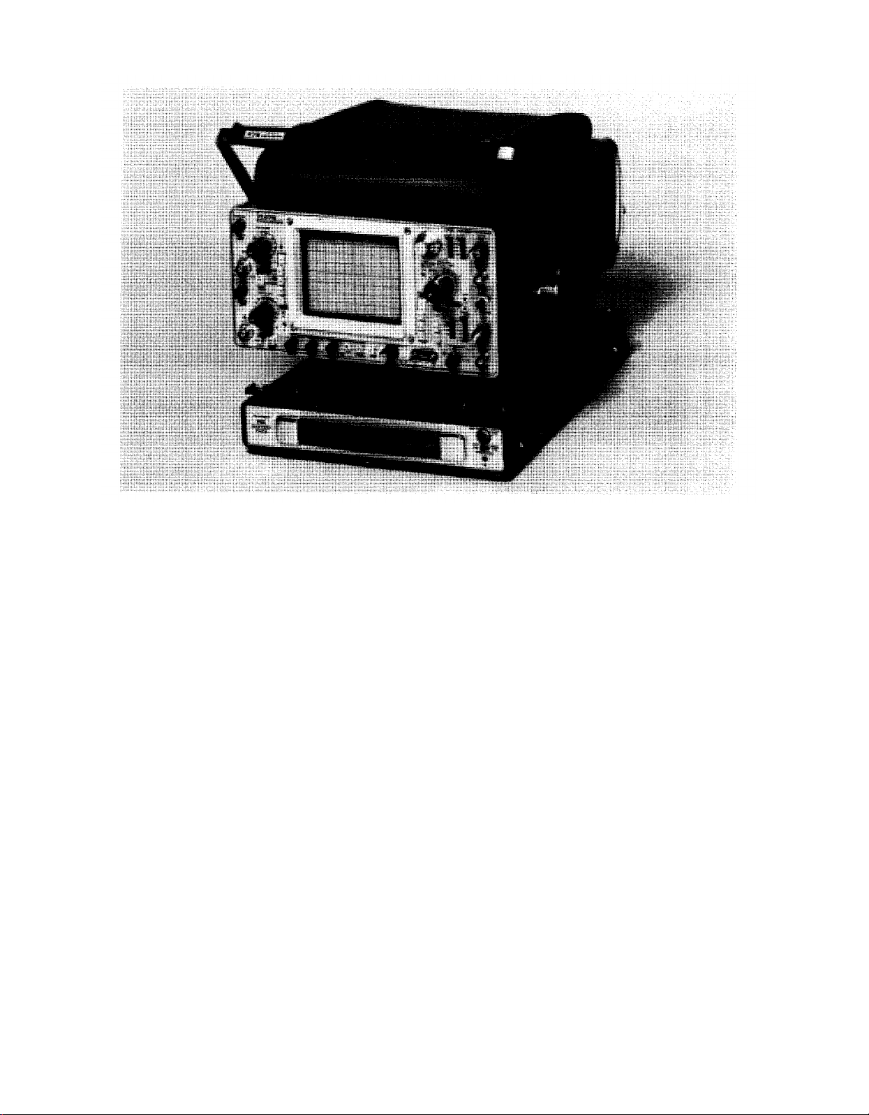
Figure 1-1. Power Supply PP-7549/U (1106 Battery Pack) Being Instlled Under a Portable Oscilloscope.
1-0
Page 6

CHAPTER I
INTRODUCTION
Section I.
1-1. Scope
This manual describes Power Supply PP-7549/U
(fig. 1-1) and provides instructions for its in-
stallation, operation, and maintenance. Power Supply PP-7549/U is the joint Army-Navy nomenclature and type number which has been applied to
the commercially available Tektronix Model 1106
Battery Pack.
1-2. Index of Technical Publications
Refer to the latest issue of DA Pam 310-4 to deter-
mine whether there are new editions, changes, or ad-
ditional publications pertaining to the equipment.
1-3. Maintenance Forms, Records, and Reports
a. Reports of Maintenance and Unsatisfactory
Equipment. Department of the Army forms and
procedures used for equipment maintenance will be
those prescribed by TM 38-750, The Army Main-
tenance Management System.
b. Report of Packaging and Handling Deficien-
cies. Fill out and forward SF 364 (Report of
Discrepancy (ROD)) as prescribed in AR
735-11-2/DLAR 4140.55/NAVMATINST 4355.73/
AFR 400-54/MCO 4430.3E.
c. Discrepancy in Shipment Report (DISREP) (SF
361). Fill out and forward Discrepancy in Shipment
Report (DISREP) (SF 361) as prescribed in AR
55-38/NAVSUPINST 4610.33B/AFR 75-18/MCO
4610.19C/DLAR 4500.15.
GENERAL
1-4. Reporting Equipment Improvement
If your Power Supply PP-7549/U needs im-
provement, let us know. Send us an EIR. You, the
user, are the only one who can tell us what you don’t
like about your equipment. Let us know why you
don’t like the design. Tell us why a procedure is hard
to perform. Put it on an SF 368 (Quality Deficiency
Report). Mail it to Commander, US Army Communications-Electronics Command, ATTN: DR-
SEL-ME-MQ, Fort Monmouth, NJ 07703. We’ll
send you a reply.
1-5. Administrative Storage
Administrative storage of equipment issued to and
used by Army activities will have preventive main-
tenance performed in accordance with the PMCS
charts before storing. When removing the equip-
ment from administrative storage the PMCS should
be performed to assure operational readiness.
Disassembly and repacking of equipment for ship-
ment or limited storage are covered in paragraphs
2-1 and 2-2.
1-6. Destruction of Army Electronics Materiel
Destruction of Army electronics materiel to prevent
enemy use shall be in accordance with TM
750-244-2.
Recommendations (EIR)
Section Il. DESCRIPTION AND DATA
1-7. Purpose and Use
Power Supply PP-7549/U is a dc power source for
operating portable Oscilloscope OS-261/U
(Tektronix Model 475 Option 7) away from ac power
sources. Power Supply PP-7549/U is sold commercially as a Tektronix, Model 1106 Battery Pack.
Power Supply PP-7549/U is also referred to as the
battery pack throughout this manual.
1-8. Description
Power Supply PP-7549/U is a self-contained por-
table battery pack equipped with a dc cable for connecting to an oscilloscope allowing operation away
from ac power recepticals. It also has an ac cable
which enables connection to an ac circuit for
recharging.
1-9. Use Option
a. The separate battery pack capability permits a
choice of battery operation or ac line operation.
During charging of the battery pack, the
oscilloscope may be operated from the ac line
without detaching the battery pack.
oscilloscope may be detached from the battery pack,
while it is charging, and used elsewhere with either
another battery pack or ac line. The battery pack
and oscilloscope may be separated easily and
quickly for carrying ease.
The
1-1
Page 7

b. Refer to the oscilloscope technical manual for
information regarding input power switch position
when changing to or from battery pack operation.
1-10. Specifications
a. AC Requirements.
Ac power source is required
only for battery charging. Standard instrument: 100
to 132 Vac or 200 to 264 Vac, 50 to 400 Hz. Standard instrument with an internal connection
change: 90 to 120 Vac or 180 to 240 Vac, see the
maintenance section of this manual for further information 50 to 400 Hz. Power line consumption is
40 watts maximum at 115 Vac, 60 Hz.
b. Power Output. 22 to 24 Vdc for 7 ampere-
hours. 5 A maximum.
Section Ill. SAFETY CONSIDERATIONS
c. Battery Operating Time. Approximately 140
watt-hours from fully-charged batteries.
d. Battery Charge Time. 14 to 16 hours (0° C to
40° C).
e. Temperature.
Operating, 0° C to 40° C. 0° C to
40° C will not noticeably reduce the battery
capacity. Storage outside this range will reduce bat-
tery efficiency and capacity. Non-operating; with
batteries
-40° C to +60° C; without batteries,
-55° C to +75° C.
f. Physical. Weight is 16 pounds. 11.5 inches
wide. 17.0 inches long, including feet and handle. 2.6
inches high, including feet. Combined height of battery pack and oscilloscope is approximately 8.4 inches.
1-11. Charging
--
The instrument is intended to be operated from a
single-phase ac power source having one currentcarring conductor (the Neutral Conductor) at
ground (earth) potential. Operation from power
sources where both current-carrying conductors are
live with respect to ground (such as phase-to-phase
Table 1-1. Power Cord Conductor Identification
Conductor
Ungrounded (Line)
Grounded (Neutral)
Grounding (Earthing)
Brown
Blue
Green-Yellow
1-13. AC Power Cord
The instrument has a three-wire power cord with a
three-terminal polorized plug for connection to the
power source and safety-earth. The ground (earth)
terminal of the plug is directly connected to the in-
strument frame. For electric-shock protection, in-
sert this plug only in a mating outlet with a safety
earth contact.
on a three-wire system) is not recommended, since
only the Line Conductor has over-current (fuse)
protection within the instrument.
1-12. Power Cord Conductor Identification
Identification of power cord conductors is contained
in table 1-1.
Color
Alternate Color
Black
White
Green-Yellow
1-14. Operating
a. The potential at the chassis (frame) of the battery pack is established by the oscilloscope being
powered through the safety-earth conductor
system. For electric-shock protection, connect the
oscilloscope cabinet (frame) to a ground (earth)
reference.
b. If the battery pack ac power cord is connected
to a correctly-wired ac power source, an additional
shock protection circuit is established through the
safety-earth conductor system.
1-2
Page 8

CHAPTER 2
SERVICE UPON RECEIPT AND INSTALLATION
Section I. SERVICE UPON RECEIPT
2-1. Packaging Data
a. Power Supply PP-7549/U may arrive packed
for either domestic or overseas shipment.
b. When Power Supply PP-7549/U is packed for
overseas shipment it is placed in a lightweight
packing material and is placed in a corrugated carton. The carton is sealed with gummed tape. The
boxed equipment is then placed in a moisturevaporproof barrier, which is heat-sealed, and this
package is placed in a waterproof corrugated carton.
The technical manuals are placed under the lid and
the carton is sealed with waterproof tape. The
packaged battery pack is placed in a wooden shipping container with a waterproof case liner. The
wooden container is reinforced with flat metal
straps.
2-2. Unpacking
a. For unpacking overseas shipment equipment,
proceed as follows:
(1) Cut the metal straps with a suitable cutting
tool, or twist them with pliers until the straps break.
Remove the straps.
(2)
Remove the nails from the top and one side
of the wooden case. Do not attempt to pry off the
sides and top. Such action may damage the equipment.
(3) Remove the corrugated filler from the
packing case and lift the packaged equipment out of
the case.
the sealed moisture-vaporproof barrier. Lift out the
inner corrugated carton.
remove the battery pack. Read and observe the
charging instructions fully before connecting the
battery pack to an oscilloscope.
packing cases. The instructions given in a above,
also apply to unpacking domestic shipments. If
heavy wrapping paper has been used, remove it
carefully and take out the battery pack.
2-3. Check Unpacked Equipment
during shipment. If the equipment has been
damaged, report the damage on SF 964 (para 1-3b).
the packing slip.
Report all discrepancies in accordance with
paragraph 1-3. The equipment should be placed in
service even though a minor assembly or part that
does not affect proper functioning is missing.
modified. Modified equipment will have the MWO
number on the front panel near the nomenclature
plate. Check also to see whether all currently applicable MWO’s have been applied. (Current MWO’s
are listed in DA Pam 310-4).
checked, clean with a soft cloth.
(4) Open the outer corrugated carton and break
(5) Open the inner corrugated carton and
b. The battery pack may be received in domestic
a. Inspect
b. Check the equipment for completeness against
c. Check to see if the equipment has been
d. After the equipment has been thoroughly
the equipment for damage incurred
Section II. INSTALLATION
2-4. Attaching The Battery Pack
a. The battery pack is equipped with four permanently attached clamps that are designed to fit
and attach to the feet of the portable Oscilloscope
OS-261 (Tektronix Model 475 Option 7). Set the
oscilloscope on the battery pack and observe that
the oscilloscope feet seat properly in the clamps.
Press the moveable part of the clamp inward until a
positive fit is accomplished.
b. The dc power cord attached to the battery pack
is to be plugged into the dc socket of the
oscilloscope. Refer to chapter 3 prior to placing the
battery pack into operation.
c. The ac power cord to the battery pack is not
used while the battery pack is in operation. Store
this ac cord in a method so that it will not incur
damage during movement of the oscilloscope and
battery pack from one working area to the next.
d. It may be advantageous to use the battery
pack and the oscilloscope as separate units as each
item is equipped with its own carrying handle. With
care, the two units may be carried short distances
by two persons without disconnecting the dc power
cord while still in the operational mode, thus
realizing the full portability of these two units.
2-1
Page 9

CHAPTER 3
OPERATING INSTRUCTIONS
Section I. FUNCTION OF CONTROLS AND CONNECTORS
3-1. Battery Level
Meter indicates the approximate state of charge of
the batteries while under load.
3-2. Charger
a. Mode Switch.
(1) Full. Permits the maximum safe charging
rate. Charge rate should be changed to the tricklecharge rate when the batteries have received a full
charge.
(2) Trickle. Reduces the charging rate to main-
tain fully-charged batteries.
Charging occurs as long as the battery pack is con-
nected to the ac power line.
operation.
oscilloscope external dc input.
charger circuit only, as long as the ac line is con-
netted.
Section Il. OPERATION AND INSPECTION
3-3. First-Time Operation
The instrument may be operated with less than fully
charged batteries.
however, charge the batteries at the full-charge rate
for 14 to 16 hours.
3-4. Attaching the Battery Pack
Attach the battery pack to an oscilloscope with Option 7 as follows (see fig. 1-1):
a. Open the latches on the battery pack by pulling
them outward. Set the oscilloscope on top of the battery pack with the feet in the holes in the latches.
Push the latches in until they lock in the feet of the
For first-time
operation,
oscilloscope. Check each corner to verify that each
foot has been latched to the battery pack.
connect the battery pack output to the oscilloscope
(Option 7) dc input. Turn the oscilloscope on. Check
that the battery pack powers the oscilloscope. Observe the BATTERY LEVEL meter. The meter
reading is only indicative of the remaining charge if
the battery pack if powering an oscilloscope. Under
no-load conditions, the battery pack will read full,
even if it is almost discharged.
th) reference before using.
b. ON Position. Lamp indicates charger is on.
c. Line Selector. Select 115 Vac or 230 Vac
d. DC Output (Attached Cord). Connects to the
e. AC Input. Allows ac operation of the battery
b. Set the oscilloscope for 24 Vdc operation and
c. Connect the oscilloscope frame to a ground (ear-
Section III.
WARNING
The nickel-cadmium (NiCd) cells used in
this instrument are capable of delivering
a large amount of current in a short time.
Care must be taken not to short-circuit
the cells. The battery pack is fused at 6
amperes.
Operating Time
3-5.
Battery operating time depends on the load
a.
BATTERY OPERATION
selected and the charge-discharge temperatures. Op-
timum charge and discharge is obtained when the
batteries are operating at temperatures between 20°
C to 30° C. Relative capacities for other tem-
peratures are shown in table 3-1. Battery pack
discharge curves are given in figure 3-1.
b. Optimum operating time is obtained by having
the battery pack vertical (handle on top) during bat-
tery charging.
3-1
Page 10
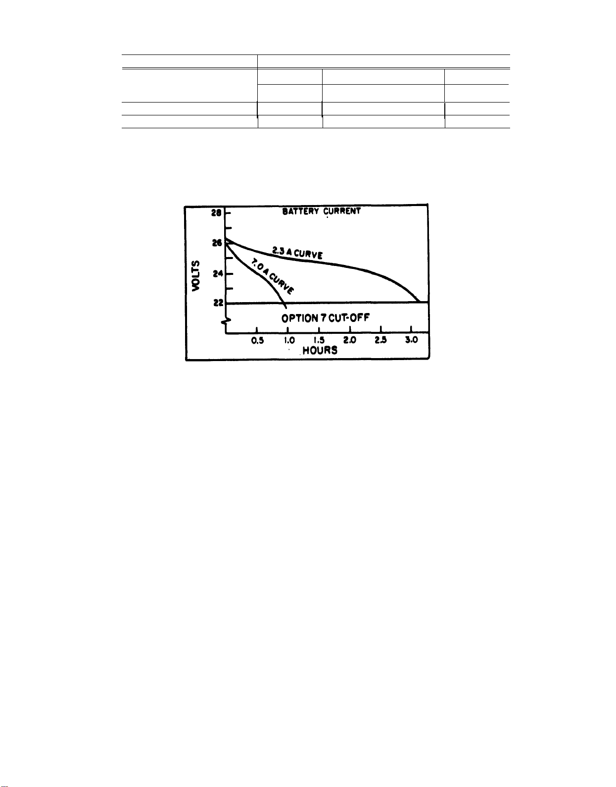
Table 3-1. Typical Battery Charge Capacity (referenced to charge-discharge at +20° C to +30° C)
Charge Temperature
-15° C
0° C
+20° C to +30° C
+40° C
c. The approximate battery pack operating time
may be roughly estimated using figure 3-1. For in- manual.
dividual oscilloscope times see the Option 7
40%
65%
40%
Specification portion of the oscilloscope technical
Operating Temperature
+20°
C to +
60%
100%
65%
30° C
+55° C
50%
85%
55%
Figure 3-1. Typical Battey-Pack Discharge Curves.
NOTE
High discharge rates or high ambient
temperatures may raise the battery tem-
The batteries may be damaged by over-charging for
long periods (in excess of 24 hours). Repeated over-
charging shortens the useful life of the batteries.
perature enough to lower their 140 watthour capability.
cell in the battery pack acquires a slightly different
charge characteristic. To provide the best overall
3-6. Battery Discharge
Extensive discharge of the batteries may cause one
or more of the cells to reverse polarity. Repeated
reversal shortens the useful life of the batteries. The
oscilloscope with the Option 7 has a circuit to cut off
its inverter when the external dc source drops below
approximately 22 Vdc. This prevents the battery
operation and maximum operating life, the charge
on the individual battery cells should be equalized
periodically. This can be done without damage to
the battery cells by charging the batteries at the
full-charge rate for 24 hours. Charging should be
done after every 15 charge-discharge cycles or every
30 days, whichever occurs first.
from going into deep discharge.
mode switch to trickle charge if the battery pack is
3-7. Battery Charge
a. A thermal cutout in the battery pack protects
the batteries from overheating during charge time.
The batteries normally become warmer as they
to remain connected to the ac line. This maintains
fully-charged batteries and prevents overcharging.
3-8. Battery Pack Storage
reach full charge potential. If the temperature
surrounding the batteries exceeds the safe operating
level, a thermal cutout switches the charge rate
from 620 milliamperes full-charge to the 60-milliampere trickle-charge rate. When the temperature
returns to a safe operating level, the thermal cutout
returns the charge rate to the 620-milliampere level.
be stored in a charged condition. For best shelf life,
when storing the battery pack for long periods of
time, remove fuse F131 (which may be stored by
placing it in the dc power cord clip on the rear panel).
Fully recharge the batteries about every three
months.
EL6RK002
b. During normal usage or storage, each battery
c. Once the batteries are fully charged, change the
a. The batteries used in the battery pack should
3-2
Page 11

b. Charge retention characteristics of nickelcadmium batteries vary with the storage temperature and humidity. The battery pack may be
stored at ambient temperatures between —40° C
and +60° C without damage, either in the instrument or as a separate unit. The self-discharge
rate increases with an increase in ambient tem-
perature. For example, cells stored at +20° C will
lose about 50% of their stored charge in three mon-
ths, but when stored at +50° C, they will be almost
completely self-discharged in only one month. High
humidity also increases the rate of self-discharge.
3-9. Maintenance
Additional data regarding maintenance and repair
of the battery pack and the NiCd cells can be found
in the maintenance section of this manual.
310. Battery Charge Level
a. Meter indication of battery charge level may be
false during the first several minutes of battery
operation. This is due to a battery characteristic.
b. When the battery pack is turned on, a residual
battery charge may give a meter indication of a high
state-of-charge even though a low, partial charge is
all that remains. The battery pack may operate
several minutes, under load, before this partial
charge is depleted.
c. This characteristic may show up after the bat-
tery pack has been discharged and the instrument
turned off. It may also show up after the instrument
has been stored in temperatures significantly below
25° C, then brought to room temperature for
operation.
d. If unsure of the state of the battery charge,
recharge at the proper temperature for the full
recharge time given in the battery operation section.
3-3
Page 12

CHAPTER 4
THEORY OF OPERATION
Section I. CIRCUIT DESCRIPTION
4-1. General
a. The battery pack provides a 24 Vdc power
source. The charger circuit will charge, at either fullcharge or trickle-charge rates, as long as the battery
pack is connected to the correct ac line. The meter
circuit is always on. The output voltage is always
available at the DC OUT plug. The batteries may be
disconnected from the meter and charger circuitry
by removing fuse F131.
b. Refer to the complete schematic in chapter 6
throughout the following circuit description.
4-2. Battery Charger Circuit
a. From the secondary of transformer T101, ac
voltage is applied to full-wave bridge rectifier
CR115. The rectified voltage goes to filter C115 and
through CR121 to resistor R121 and transistor
Q124. VR123 sets the bias for Q124. This bias is
about 5.6V across the R123 and the emitter-base
junctions of Q124, a Darlington transistor. The drop
across the two emitter-base junctions reduces this
voltage to about 4.3 V across R123.
b. In parallel with R123 is the series combination
of CR125, S125, S130, and R131. The charge rate
switch S130 is shown in the FULL CHG position
(closed). Under normal battery temperatures, thermal cut-out S125 is closed and the 4.3 V is across
R131 (in series with CR125). This limits the charge
current to about 620 milliamperes.
c. Battery temperature rises as the batteries
reach full charge. S125 opens, removing resistor
R131 from the circuit. The charging current is now
limited to about 60 milliamperes by the 4.3 V being
applied only across R123. The same current reduction occurs when the charge rate switch (S130) is set
to TRICKLE CHG (open).
4-3. Charger Circuit Protection
a. Power dissipated by Q124, in the full-charge
mode, is reduced for high line or low battery conditions by the circuitry involving C117, CR111,
CR112, R125, and T101.
biased. An increase in line voltage increases the
potential from the -DC OUT line to the collector of
Q124 and also to CR112 and CR111. Q124 provides
a constant current to a fixed load (R123 and R131).
The increased potential, therefore, appears across
Q124, increasing its dissipation.
CR111 and CR112 to conduct. This point is determined by the taps on T101. Once CR111 and CR112
conduct, they maintain a voltage at the plus side of
C117 that is about 70% of the voltage at the plus side
of C115 (with respect to the -DC OUT line). As the
voltage across C117 increases, current through
R125 increases. There is a corresponding decrease in
current supplied by Q124. This current reduction in
Q124 decreases the power dissipated in Q124. Since
the current through R125 is supplied from a lower
voltage source than is the current through Q124,
there is a reduction in total power.
same effect on the circuit as an increase in line
voltage. Batteries with a low charge and with a high
ac line may receive nearly all of the charging current
through CR111, CR112, and R125.
conditions, from bypassing the charge rate switch
when it is in the TRICKLE CHG mode. CR 121
prevents C115 from charging through Q124. This
situation can exist if the battery pack has been off
for a long time, a dead battery is replaced, F131 is
replaced, or a similar condition exists that permits
C115 to discharge, then apply voltage across the
+DC OUT line.
4-4. Meter Circuit
The voltage reference for the meter circuit is set by
R127 and VR131. The other side of the meter is connected to voltage divider R128, R133, and R136.
R133 is set for a meter reading at the junction of the
red and green portions of the meter scale (a reading
at the left end dot for early SN instruments).
b. At low line, CR111 and CR112 are reverse
c. At some point the increased line voltage causes
d. A low charge on the batteries will have the
e. CR125 prevents the current, during high line
4-1
Page 13

Section Il. OPERATION UNDER UNUSUAL CONDITIONS
4-5. Operation in Arctic Climates
Subzero temperatures and climatic conditions
associated with cold weather may hamper the efficient operation of electronic equipment. Instructions and precautions for operation under such
adverse conditions follow:
a. Keep the equipment warm and dry. If the
equipment is not kept in a heated enclosure, construct an insulated box for its protection.
b. Make certain the equipment has been warmed
up sufficiently before use. This may take 15 to 30
minutes, depending on the temperature of the
surrounding air.
c. When equipment which has been exposed to
the cold is brought into a warm room, it will sweat
until it reaches room temperature. When the equipment has reached room temperature, dry it
thoroughly.
4-6. Operation in Tropical Climates
In tropical climates, electronic equipment may be installed in tents, huts or, when necessary, in underground dugouts. When equipment is installed
below ground, and when it is set up in swamp areas,
danger of moisture damage is more acute than normal in the tropics. Ventilation is usually very poor,
and the high relative humidity cuases condensation
on the equipment whenever its temperature
becomes lower than the ambient air. To counteract
this condition, place lighted electric bulbs under the
equipment.
4-7. Operation in Desert Climates
The main problem with electronic equipment in
desert areas is the large amount of sand and dust
that lodges in the moving parts and mechanical
assemblies. Cleaning and servicing intervals should
be shortened according to local conditions.
4-2
Page 14

CHAPTER 5
MAINTENANCE
Section I. TROUBLESHOOTING
5-1. General
The first step in servicing a defective battery pack is
to sectionalize the fault. Sectionalization means
tracing the fault to the major circuit responsible for
the abnormal operation. The second step is to
localize the fault. Localization means tracing the
fault to a particular stage or network within one of
the major circuits. The third step is to isolate the
fault. Isolation means tracing the fault to the defec-
tive part responsible for the abnormal condition.
Some faults, such as burned-out resistors, arcing
and shorted transformers, can often be located by
sight, smell, and hearing. The majority of faults,
however, must be isolated by checking voltages and
resistances.
5-2. Component Sectionalization, Localization,
Listed below is a sequence of tests arranged to
reduce unnecessary work and aid in tracing the
trouble to a specific component.
the trouble may frequently be discovered or the circuit in which the trouble exists may be determined.
This inspection helps to avoid additional damage to
the equipment as a result of improper servicing
methods.
connections may cause the trouble. Test wiring for
loose connections and move wires and components
with an insulated tool. This may indicate the
location of a faulty connection or component.
6-4 for troubleshooting voltage checks, symbols,
and schematic diagram.
Section II. BATTERY SERVICE
5-3. Tools and Test Equipment Required
The following is a list of common tools and test
equipment required for general support maintenance.
a. Multimeter ME-451/U, NSN 6625-01-
060-6804.
b. Battery Charger PP-6241/U, NSN 6130-00-
106-6445.
c. Tool Kit, Electronic Equipment TK-100/G,
NSN 5180-00-605-0079.
5-4. Batteries
a. The battery pack contains twenty 1.25 V
Nickel-Cadmium (NiCd) cells, in groups of four,
strapped together. Background information regarding these cells is given in chapter 3, section III battery operation and should be read before any servicing is performed on the battery pack.
b. If one group of cells is defective and fails while
the rest of the battery pack is still quite new, that
group may be replaced without undue concern. The
Tektronix Field Representative or Office should be
consulted before cells are replaced, if the warranty is
still in effect.
c. Gas evolution and recombination takes place
during battery charging. This creates a pressure
within the cells which they normally can withstand.
If a cell becomes defective, or a circuit failure causes
the recommended charge rate to be exceeded, excessive pressure builds up. The pressure may rup-
ture a relief vent, exhausting the gas. This action
may shorten the life of the cell, and will coat the
surrounding areas with a corrosive substance.
5-5. Battery Removal
Remove the six screws from the sides of the battery
pack. Remove the cover. Remove fuse F131.
Remove the two screws from the battery clamps.
Unsolder the wires at the batteries.
5-6. Cell Replacement
removed and replaced by cutting the straps that
connect the two ends of the cell group to the pack,
and soldering a new group of four cells. Single cell
replacement should not be attempted. The cell type
specified must be used. Other types may not func-
tion properly. They may prove to be a hazard to the
instrument and to personnel. Operating time or tem-
perature performance may be degraded. The battery
and Isolation
a. Visual Inspection. Through inspection alone,
b. Intermittents. It is possible that some external
c. Voltage Checks. Refer to figures 6-2, 6-3, and
a. When necessary, a group of four cells can be
5-1
Page 15

pack should be charged for 24 hours after cells are
replaced.
b. All cells in the battery pack should be made by
the same manufacturer. Include this information,
with the other information required, when ordering
replacement cells.
5-7. Line voltage Selection Wiring
a The battery pack can be wired
to accept a
100 TO 132 VAC
variation in input voltage as may exist in certain
conditions or geographical areas. The wires on transformer T101 may be changed to accept line
variation. Proper wiring of the input will result in
satisfactory battery pack charging.
b. Refer to figure 5-1 for line voltage selection
wiring. For nominal 115 Vat, use the 100 to 132
-
VAC
diagram. For nominal 105 Vat, use the 90 to
120 VAC diagram.
90 TO 120 VAC
EL6RK003
Figure 5-1. Line Voltage Section Wiring.
5-2
Page 16

CHAPTER 6
CALIBRATION
Section I. GENERAL
6-1. Terms and Definition
a. Calibration, in accordance with maintenance
practices, is the checking of voltages, current,
resistances, etc., through each section or stage, and
the adjusting and alignment of variable components
within each section or stage. It is almost always
necessary to perform this type of calibration while
the equipment is being electrically repaired or as
parts are being replaced. Common maintenance test
equipment is used for this type of calibration.
Section II.
6-2. Battery Pack Disassembly
a. For calibration during maintenance, remove
the six screws from the sides of the battery pack and
CALIBRATION DURING MAINTENANCE
(US Army Calibration System), is a periodic check
of the total accuracy of each parameter as compared
to calibrated standards at a ratio of 4 to 1. Upon
completion of this type of calibration a Department
of the Army DA Label 80 is affixed to the accepted
unit.
requirements for the maintenance of Army materiel
is contained in TB 43-180 and TM 38-750.
lift the cover.
ploded view in figure 6-1.
b. Calibration, in accordance with AR 750-25-1
All information regarding calibration
b. For further mechanical disassembly see the ex-
6-1
Page 17

Figure 6-1. Battery Pack PP-75/U, Exploded View.
WARNING
Dangerous potential and high current
capabilities exist at several points.
Disconnect power cord, remove fuse
F131, and unsolder batteries before
replacing parts.
6-3. Equipment Required
DC Milliammeter: 620 mA and 60mA. Voltmeter:
/VDC and 5,000
Variable DC Power Source: 21 to 24 V at 10 mA.
NOTE
The battery pack is calibrated at the factory using a power supply permitting ac-
6-2
curate setting of the meter zero. Because
this type of power supply may not be
available, an alternate method is given.
The accuracy of the equipment required
depends on how critically the user wants
the meter zero to coincide with the cut-off
point in the Option 7 circuitry.
Calibration Procedure
6-4.
a.
Charge.
(1) Remove fuse F131, (figure 6-2). Connect the
ammeter across the terminals for F131. Connect the
battery pack to the correct ac line. Set the mode
switch to FULL CHG.
Page 18

Voltmeter: 20,000 Ω/ς∆Χ and 5,000 Ω/ςΑΧ multimeter.
Voltage readings will vary with line voltage and battery
charge level.
Battery charged
Line Selector: Correct line voltage
Mode Switch: FULL CHG
Figure 6-2. Battery Pack PP-7549/U, Circuit Board, with Test Voltages and Conditions.
(2) Current should be approximately 620 mA.
(3) Change mode switch to TRICKLE CHG.
junction of the red and green portions of the scale (or
near the left end dot for SN below B022417).
(4) Current should be approximately 60 mA.
b. Zero Adjust.
(1) Disconnect the battery pack from the ac
line. Disconnect the external milliammeter but do
reading at the junction of the red and green portions
of the scale (for SN below B022417 adjust R133 for
a meter reading at the left end dot).
not install F131. Connect a 23 V power source to the
DC OUT connector (for SN below B022417 use a 22
F131.
V source).
(2) Battery level meter should read near the
manner as disassembled in paragraph 6-2.
(3) Adjust Meter Level (R133) (fig. 6-2) for a
(4) Remove the dc power source and install fuse
(5) Reassemble the battery pack in the opposite
6-3
Page 19

CIRCUIT BOARD ILLUSTRATION, DIAGRAM, AND
PARTS LISTS
Symbols
Electrical components shown on the diagrams are in the following units unless noted otherwise:
Capacitors = Values one or greater are in picofarads (pF).
Resistors = Ohms
Symbols used on the diagrams are based on USA Standard Y32.2-1967.
Logic symbology is based on MIL-STD-8068 in terms of positive logic.
and may differ from the manufacturer’s data.
Values less than one are
in microfarads (µF).
Logic symbols depict the Iogic function performed
Internal Screwdriver Adjustment
Test Voltage
Plug to E.C. Borad
Panel Adjustment
Plug Index
Modified Component–See Parts List
Refer to Waveform
Refer to Diagram Number
Coaxial Connector
Panel Connector
Assembly Number
Board Name
Etched Circuit Board
Figure 6-3.
Schematic Name and Number
Battery Pack PP-7549/U, Vertical Amplifier Schematic with Explanation of Electrical Symbols.
6-4
Page 20

NOTE:
DENOTES COMMON
NEGATIVE RETURN
Figure 6-4. Battery Pack PP-7649/U, Schematic Diagram.
6-5
Page 21

APPENDIX A
REFERENCES
DA Pam 310-4
TB 43-180
TB 43-0118
TM 11-6130-351-14
TM 11-6625-2953-14
TM 38-750
TM 740-90-1
TM 750-244-2
Index of Technical Publications.
Calibration Requirements for the Maintenance of Army Materiel.
Field Instructions For Painting and Preserving Electronics Command Equip-
ment Including Camouflage Pattern Painting of Electrical Equipment
Shelters.
Operator’s, Organizational, Direct Support, and General Support Main-
tenance Manual Including Repair Parts and Special Tools Lists (Including
Depot Maintenance Repair Parts and Special Tools) for Battery Charger
PP-6241/U.
Operator’s, Organizational, Direct Support, and General Support Main-
tenance Manual for Multimeter AN/USM-451.
The Army Maintenance Management System (TAMMS).
Administrative Storage of Equipment.
Procedures for Destruction of Electronics Materiel to Prevent Enemy Use
(Electronics Command).
A-1/(A-2 Blank)
Page 22

APPENDIX B
MAINTENANCE ALLOCATION
Section I. INTRODUCTION
B-1. General
This appendix provides a summary of the main-
tenance operations for the PP-7549/U. It authorizes
categories of maintenance for specific maintenance
functions on repairable items and components and
the tools and equipment required to perform each
function. This appendix may be used as an aid in
planning maintenance operations.
B-2. Maintenance Function
Maintenance functions will be limited to and defined
as follows:
a. Inspect. To determine the serviceability of an
item by comparing its physical, mechanical, and/or
electrical characteristics with established standards
through examination.
b. Test. To verify serviceability and to detect in-
cipient failure by measuring the mechanical or elec-
trical characteristics of an item and comparing
those characteristics with prescribed standards.
c. Service. Operations required periodically to
keep an item in proper operating condition, i.e., to
clean (decontaminate), to preserve, to drain, to
paint, or to replenish fuel, lubricants, hydraulic
fluids, or compressed air supplies.
d. Adjust. To maintain, within prescribed limits,
by bringing into proper or exact position, or by setting the operating characteristics to the specified
parameters.
e. Align. To adjust specified variable elements of
an item to bring about optimum or desired performance.
f. Calibrate. To determine and cause corrections
to be made or to be adjusted on instruments or test
measuring and diagnostic equipments used in
precision measurement. Consists of comparisons of
two instruments, one of which is a certified standard
of known accuracy,
discrepancy in the accuracy of the instrument being
compared.
g. Install. The act of emplacing, seating, or fixing
into position an item, part, module (component or
assembly) in a manner to allow the proper func-
tioning of the equipment or system.
h. Replace. The act of substituting a serviceable
like type part, subassembly, or module (component
or assembly) for an unserviceable counterpart.
i. Repair. The application of maintenance ser-
to detect and adjust any
vices (inspect, test, service, adjust, align, calibrate,
replace) or other maintenance actions (welding, grinding, riveting, straightening, facing, remachining,
or resurfacing) to restore serviceability to an item
by correcting specific damage, fault, malfunction, or
failure in a part, subassembly, module (component
or assembly), end item, or system.
vice/action) necessary to restore an item to a com-
pletely
prescribed by maintenance standards (i.e., DMWR)
in appropriate technical publications. Overhaul is
normally the highest degree of maintenance performed by the Army. Overhaul does not normally
return an item to like new condition.
necessary for the restoration of unserviceable equipment to a like new condition in accordance with
original manufacturing standards. Rebuild is the
highest degree of materiel maintenance applied to
Army equipment. The rebuild operation includes the
act of returning to zero those age measurements
(hours, miles, etc.) considered in classifying Army
equipments/components.
B-3. Column Entries
group numbers, the purpose of which is to identify
components,
modules with the next higher assembly.
contains the noun names of components, assemblies, subassemblies, and modules for which maintenance is authorized.
lists the functions to be performed on the item listed
in column 2. When items are listed without maintenance functions, it is solely for purpose of having
the group numbers in the MAC and RPSTL coincide.
specifies, by the listing of a “work time” figure in
the appropriate subcolumn(s), the lowest level of
maintenance authorized to perform the function
listed in column 3. This figure represents the active
time required to perform that maintenance function
at the indicated category of maintenance. If the
number or complexity of the tasks within the listed
j. Overhaul. That maintenance effort (ser-
serviceable/operational
k. Rebuild. Consists of those services/actions
a. Column 1, Group Number. Column 1 lists
assemblies,
b. Column 2, Component/Assembly. Column 2
c. Column 3, Maintenance Functions. Column 3
d. Column 4, Maintenance Category. Column 4
subassemblies,
condition as
and
B-1
Page 23

maintenance function vary at different maintenance
categories, appropriate “work time” figures will be
shown for each category. The number of task-hours
specified by the “work time” figure represents the
average time required to restore an item (assembly,
subassembly, component, module, end item or
system) to a serviceable condition under typical
field operating conditions. This time includes
preparation time, troubleshooting time, and quality
assurance/quality control time in addition to the
time required to perform the specific tasks identified for the maintenance functions authorized in
the maintenance allocation chart. Subcolumns of
column 4 are as follows:
C–Operator/Crew
O–Organizational
F–Direct Support
H–General Support
D–Depot
e. Column 5, Tools and Equipment. Column 5
specifies by code, those common tool sets (not individual tools) and special tools, test, and support
equipment required to perform the designated function.
f. Column 6, Remarks. Column 6 contains an
alphabetic code which leads to the remark in section
IV, Remarks, which is pertinent to the item opposite the particular code.
B-4. Tools and Test Equipment Requirements
numbers in this column coincide with the numbers
used in the tools and equipment column of the MAC.
The numbers indicate the applicable tool or test
equipment for the maintenance functions.
column indicate the maintenance category allocated
the tool or test equipment.
name and nomenclature of the tools and test equipment required to perform the maintenance functions.
lists the National/NATO stock number of the
specific tool or test equipment.
turer’s part number of the tool followed by the
Federal Supply Code for manufacturers (5-digit) in
parentheses.
B-5. Remarks (Sec IV)
propriate item in section II, column 6.
explanatory information necessary to clarify items
appearing in section II.
(See III)
a. Tool or Test Equipment Reference Code. The
b. Maintenance Category. The codes in this
c. Nomenclature. This column lists the noun
d. National/NATO Stock Number. This column
e. Tool Number. This column lists the manufac-
a. Reference Code. This code refers to the ap-
b. Remarks. This column provides the required
(Next
printed page is B-3)
B-2
Page 24

TM 11-6625-2978-14
(I)
GROUP
NUMBER
00
01
02
COMPONENT/ASSEMBLY
POWER SUPPLY PP-7549/U
STORAGE BATTERY BT-131
CIRCUIT CARD ASSY (A1)
SECTION II MAINTENANCE ALLOCATION CHART
FOR
POWER SUPPLY PP-7549/U
0.1
0.1
(4)
F
H
O
0.5
0.5
1.0
0.1
0.1
0.2
0.2
0.1
0.5
0.2
D
5.0
0.5
(2)
(3)
MAINTENANCE
FUNCTION
Inspect
Test
Calibrate
Repair
Repair
Overhaul
Inspect
Test
Replace
Repair
Inspect
Test
Replace
Repair
MAINTENANCE CATEGORY
C
(5)
TOOLS
AND
EQPT.
1 thru 3
1 thru 3
3
1 thru 3
3
2,3
3
3
3
1 thru 3
3
3
(6)
REMARKS
DRSEL-MA Form 6031, (1 Jul 76)
B-3
HISA-FM 2314-79
Page 25

TM 11-6625-2978-14
TOOL OR TEST
EQUIPMENT
REF CODE
1
2
3
MAINTENANCE
CATEGORY
H,D
H,D
H,D
SECTION III
MULTIMETER ME-451/U
BATTERY CHARGER PP-6241/U
TOOL KIT, ELECTRONIC EQUIPMENT TK-100/G
TOOL AND TEST EQUIPMENT REQUIREMENTS
POWER SUPPLY PP-7549/U
FOR
NOMENCLATURE
NATIONAL/NATO
STOCK NUMBER
6625-01-060-6804
6130-00-106-6445
5180-00-605-0079
TOOL NUMBER
B-4
Page 26

Page 27

Page 28

Page 29

Page 30

THE METRIC SYSTEM AND EQUIVALENTS
Page 31

PIN: 050633-000
Page 32

This fine document...
Was brought to you by me:
Liberated Manuals -- free army and government manuals
Why do I do it? I am tired of sleazy CD-ROM sellers, who take publicly
available information, slap “watermarks” and other junk on it, and sell it.
Those masters of search engine manipulation make sure that their sites that
sell free information, come up first in search engines. They did not create it...
They did not even scan it... Why should they get your money? Why are not
letting you give those free manuals to your friends?
I am setting this document FREE. This document was made by the US
Government and is NOT protected by Copyright. Feel free to share,
republish, sell and so on.
– Sincerely
Igor Chudov
http://igor.chudov.com/
– Chicago Machinery Movers
 Loading...