

Page 1

User Manual
p
p
pp
OTS
Optical Test System
10 Gb/s SONET/SDH test module
071-0855-05
Page 2

Copyright © Tektronix, Inc. 2002.
All rights reserved. Licensed software products are owned by Tektronix or its suppliers and are
protected by United States copyright laws and international treaty provisions.
Tektronix products are covered by U.S. and foreign patents, issued and pending. Information in
this publication supersedes that in all previously published material. Specifications and price
change privileges reserved.
Tektronix, Inc.
14200 SW Karl Braun Drive
Beaverton, OR 97077
USA
TEKTRONIX and TEK are registered trademarks of Tektronix, Inc.
Microsoft® Windows 2000®: Copyright © Microsoft Corporation 1985 - 1996
Page 3

Warranty
Tektronix warrants that this product will be free from defects in materials and workmanship for a
period of one (1) year from the date of shipment. If any such product proves defective during
this warranty period, Tektronix, at its option, either will repair the defective product without
charge for parts and labor, or will provide a replacement in exchange for the defective product.
In order to obtain service under this warranty, Customer must notify Tektronix of the defect
before the expiration of the warranty period and make suitable arrangements for the performance
of service. Customer shall be responsible for packaging and shipping the defective product to the
service center designated by Tektronix, with shipping charges prepaid. Tektronix shall pay for
the return of the product to Customer if the shipment is to a location within the country in which
Tektronix service center is located. Customer shall be responsible for paying all shipping
charges, duties, taxes, and any other charges for products returned to any other locations.
This warranty shall not apply to any defect, failure or damage caused by improper use or
improper or inadequate maintenance and care. Tektronix shall not be obligated to furnish service
under warranty a) to repair damage resulting from attempts by personnel other than Tektronix
representatives to install, repair or service the product; b) to repair damage resulting from
improper user or connection to incompatible equipment; or c) to service a product that has been
modified or integrated with other products when the effect of such modification or integration
increases the time or difficulty of servicing the product.
THIS WARRANTY IS GIVEN BY TEKTRONIX WITH RESPECT TO THIS PRODUCT IN
LIEU OF ANY OTHER WARRANTIES, EXPRESSED OR IMPLIED. TEKTRONIX AND ITS
VENDORS DISCLAIM ANY IMPLIED WARRANTIES OF MERCHANTABILITY OR
FITNESS FOR A PARTICULAR PURPOSE. TEKTRONIX’ RESPONSIBILITY TO REPAIR
OR REPLACE DEFECTIVE PRODUCTS IS THE SOLE AND EXCLUSIVE REMEDY
PROVIDED TO THE CUSTOMER FOR BREACH OF THIS WARRANTY. TEKTRONIX
AND ITS VENDORS WILL NOT BE LIABLE FOR ANY INDIRECT, SPECIAL,
INCIDENTAL, OR CONSEQUENTIAL DAMAGES IRRESPECTIVE OF WHETHER
TEKTRONIX OR THE VENDOR HAS ADVANCE NOTICE OF THE POSSIBILITY OF
SUCH DAMAGES.
Page 4

Page 5

Table of Contents
Table of Contents
General Safety Summary ............................................................................................ v
Preface ....................................................................................................................... ix
Getting Started
Product Description ...................................................................................................1-1
OTS9100 Features and Capabilities ........................................................................1-2
Accessories ..............................................................................................................1-4
First Time Operation ..................................................................................................1-6
OTS9100 Installation ................................................................................................1-6
Removing OTS Cards ..............................................................................................1-7
Slot Positioning of OTS Cards..................................................................................1-8
Module Interconnection ..........................................................................................1-10
Power On and Software Initialization......................................................................1-11
Module Quick Check ..............................................................................................1-12
Emergency Startup Disk.........................................................................................1-14
Shutdown and Power Off........................................................................................1-14
Operating Basics
Front Panel Indicators and Connectors ...................................................................2-1
10 Gb/s Transceiver Optics ......................................................................................2-2
Receive Analysis ......................................................................................................2-5
Transmit Generation.................................................................................................2-7
Clock Trigger ............................................................................................................2-9
Software Interface Operating Basics ......................................................................2-11
User Interface .........................................................................................................2-11
Elements of the User Interface...............................................................................2-12
Navigation Window.................................................................................................2-23
Setup Property Menus .......................................................................................2-25
Transmitter - Signal ......................................................................................2-26
Transmitter - Transport Overhead ................................................................2-30
Transmitter - Path Overhead ........................................................................2-34
Transmitter - Error Insertion .........................................................................2-37
Transmitter - K1, K2 Decode ........................................................................2-40
Transmitter - IP Payload ...............................................................................2-43
Transmitter - IP Error Insertion .....................................................................2-44
Receiver - Signal ..........................................................................................2-47
Receiver - Trace Mismatch...........................................................................2-50
Receiver - IP Setup.......................................................................................2-54
Setup Summary ............................................................................................2-55
Signal Monitor Menus ........................................................................................2-56
Receiver - Transport Overhead ....................................................................2-56
Receiver - Path Overhead ............................................................................2-58
Receiver - K1, K2 Decode ............................................................................2-60
Receiver - Payload........................................................................................2-61
Test Control Menu .............................................................................................2-62
Test Control Summary..................................................................................2-64
OTS9100 User Manual i
Page 6

Measurements Menu.........................................................................................2-65
Receiver - Real-Time....................................................................................2-65
Receiver - Cumulative ..................................................................................2-67
Receiver - History .........................................................................................2-69
Receiver – IP Measurements .......................................................................2-72
Transmitter - IP Measurements....................................................................2-73
Analysis Menu ...................................................................................................2-74
Analysis – SONET/T1M1..............................................................................2-74
Analysis – SDH/G.826 ..................................................................................2-76
APS Measurements Menu.................................................................................2-78
Remote Access Setups ..........................................................................................2-81
Select Server ..........................................................................................................2-82
View Options...........................................................................................................2-83
System View...........................................................................................................2-85
SCPI Output ...........................................................................................................2-86
Results Files ...........................................................................................................2-87
Results File Management ..................................................................................2-87
Results Viewer...................................................................................................2-89
OTS System Event Printer Application ...................................................................2-99
Reference
Commands Overview .................................................................................................3-1
IEEE 488.2 System Commands ...............................................................................3-1
Remote Control Setup and Format Commands .......................................................3-1
Remote Control Port Settings...................................................................................3-2
Remote Control Lockout...........................................................................................3-2
System Configuration Queries..................................................................................3-2
Save and Restore System Settings ..........................................................................3-3
System File Management.........................................................................................3-3
System Signal Standard (OTS9100 module) ...........................................................3-3
Receiver Commands (OTS9100 module) ................................................................3-3
Received Signal Measurement Commands (OTS9100 module) .............................3-4
Received Signal Analysis Commands (OTS9100 module) ......................................3-5
Receiver Test Control (OTS9100 module) ...............................................................3-5
Transmitter Commands (OTS9100 module) ............................................................3-5
Syntax ..........................................................................................................................3-6
IEEE 488.2 Common Commands ............................................................................3-6
SCPI Commands and Queries .................................................................................3-8
Parameter Types and Formats.................................................................................3-9
Optional and Alternative Parameters......................................................................3-10
Abbreviating Commands, Queries, and Parameters..............................................3-11
Controlling Responses to Queries..........................................................................3-11
Chaining Commands and Queries .........................................................................3-12
General Rules.........................................................................................................3-13
Slot Specifiers.........................................................................................................3-13
Command Description .............................................................................................3-14
*CLS .......................................................................................................................3-14
*ESE .......................................................................................................................3-14
*ESR.......................................................................................................................3-14
*IDN ........................................................................................................................3-14
*LRN .......................................................................................................................3-14
*OPC ......................................................................................................................3-15
*RCL .......................................................................................................................3-15
*RST .......................................................................................................................3-15
*SAV .......................................................................................................................3-15
Table of Contents
ii OTS9100 User Manual
Page 7

Table of Contents
:SENSe:ANALysis:G826A:MS................................................................................3-16
:SENSe:ANALysis:G826A:PATH............................................................................3-17
:SENSe:ANALysis:G826A:RS ................................................................................3-19
:SENSe:ANALysis:GR253A:LINE...........................................................................3-19
:SENSe:ANALysis:GR253A:PATH.........................................................................3-21
:SENSe:ANALysis:GR253A:SECTion ....................................................................3-23
:SENSe:ANALysis:PATH:HPPLM ..........................................................................3-23
:SENSe:ANALysis:PATH:HPUNEQ .......................................................................3-24
:SENSe:ANALysis:PATH:LABEl:EXPEcted ...........................................................3-24
:SENSe:ANALysis:PATH:TRACe:EXPEcted .........................................................3-24
:SENSe:ANALysis:SECTion:TRACe ......................................................................3-26
:SENSe:DATA:AUTOscan:STRUcture...................................................................3-27
:SENSe:DATA:CHANnel ........................................................................................3-28
:SENSe:DATA:IP:PAYLoad:PATTern ....................................................................3-28
:SENSe:DATA:IP:STReam:INDEX ........................................................................3-28
:SENSe:DATA:PATH:TRACe.................................................................................3-28
:SENSe:DATA:PAYLoad:PATTern.........................................................................3-29
:SENSe:DATA:POH ...............................................................................................3-30
:SENSe:DATA:POS:SCRambling ..........................................................................3-30
:SENSe:DATA:RATE..............................................................................................3-31
:SENSe:DATA:SECTion:TRACe ............................................................................3-31
:SENSe:DATA:SPE:STUFfing ................................................................................3-32
:SENSe:DATA:STRUcture .....................................................................................3-32
:SENSe:DATA:TOH................................................................................................3-32
:SENSe:INPUt:THREshold.....................................................................................3-33
:SENSe:MEASure:APSTime ..................................................................................3-33
:SENSe:MEASure:HDLC........................................................................................3-35
:SENSe:MEASure:IP:PACKets...............................................................................3-36
:SENSe:MEASure:LINE:CUMUlative .....................................................................3-36
:SENSe:MEASure:LINE:WINDow ..........................................................................3-37
:SENSe:MEASure:PATH:CUMUlative....................................................................3-37
:SENSe:MEASure:PATH:WINDow ........................................................................3-38
:SENSe:MEASure:SECTion:CUMUlative ...............................................................3-39
:SENSe:MEASure:SECTion:WINDow....................................................................3-39
:SENSe:MEASure:WINDow ...................................................................................3-40
:SENSe:OPTical:INPUt:OVERload ........................................................................3-40
:SENSe:OPTical:THReshold:AUTO.......................................................................3-41
:SENSe:OVERhead:MONItor:CHANnel .................................................................3-41
:SENSe:SIGNal:STANdard ....................................................................................3-41
:SENSe:STATus:LEDS ..........................................................................................3-42
:SENSe:TEST.........................................................................................................3-44
:SENSe:TRIGger:MODE ........................................................................................3-45
:SOURce:CLOCk:SOURce ....................................................................................3-45
:SOURce:DATA:BACKground:STRUcture .............................................................3-45
:SOURce:DATA:CHANnel......................................................................................3-46
:SOURce:DATA:HDLC:IFRame:GAP ....................................................................3-46
:SOURce:DATA:IP:HEADer ...................................................................................3-46
:SOURce:DATA:IP:PAYLoad:PATTern..................................................................3-48
:SOURce:DATA:IP:STReam:INDEX ......................................................................3-49
:SOURce:DATA:IP:TRAFfic ...................................................................................3-49
:SOURce:DATA:POS:SCRambling ........................................................................3-49
:SOURce:DATA:OVERhead:PASSthru..................................................................3-49
:SOURce:DATA:PARIty:LOOP...............................................................................3-50
:SOURce:DATA:PATH:OVERhead:PASSthru .......................................................3-50
:SOURce:DATA:PATH:TRACe ..............................................................................3-51
OTS9100 User Manual iii
Page 8

:SOURce:DATA:PAYLoad:BACKground:PATTern ................................................3-52
:SOURce:DATA:PAYLoad:PATTern ......................................................................3-53
:SOURce:DATA:POH .............................................................................................3-54
:SOURce:DATA:RATE ...........................................................................................3-55
:SOURce:DATA:SECTion:TRACe .........................................................................3-55
:SOURce:DATA:SOURce.......................................................................................3-56
:SOURce:DATA:SPE:BACKground:STUFfing .......................................................3-56
:SOURce:DATA:SPE:STUFfing .............................................................................3-57
:SOURce:DATA:STRUcture ...................................................................................3-57
:SOURce:DATA:TOH .............................................................................................3-57
:SOURce:INSErt:ANOMaly.....................................................................................3-58
:SOURce:INSErt:DEFEct .......................................................................................3-60
:SOURce:INSErt:IP:ANOMaly:MODE ....................................................................3-61
:SOURce:MEASure:HDLC .....................................................................................3-62
:SOURce:MEASure:IP:PACKets ............................................................................3-63
:SOURce:OUTPut:LASER......................................................................................3-63
:SOURce:OUTPut:LASER:INFO ............................................................................3-64
:SOURce:OUTPut:LASER:INTERlock ...................................................................3-64
:SOURce:SIGNal:STANdard ..................................................................................3-64
:SOURce:TRIGger:MODE......................................................................................3-65
:STATus:PRESet....................................................................................................3-65
:SYSTem:COMMunicate:GPIB...............................................................................3-65
:SYSTem:COMMunicate:NETWork .......................................................................3-66
:SYSTem:COMMunicate:PORT .............................................................................3-67
:SYSTem:COMMunicate:SERIal:COM1A ..............................................................3-68
:SYSTem:COMMunicate:SERIal:COM2A ..............................................................3-72
:SYSTem:CONFig:MODule ....................................................................................3-75
:SYSTem:CONFig:SLOTs ......................................................................................3-76
:SYSTem:DESCription:SETUp...............................................................................3-76
:SYSTem:ERRor ....................................................................................................3-77
:SYSTem:FILEs:MGMT:RESUlts ...........................................................................3-77
:SYSTem:FORMat:BLOCk .....................................................................................3-79
:SYSTem:HEADers ................................................................................................3-79
:SYSTem:LOCK:RELease......................................................................................3-80
:SYSTem:LOCK:REQuest......................................................................................3-80
:SYSTem:SIGNal:STANdard..................................................................................3-80
:SYSTem:VERBose................................................................................................3-81
*TST .......................................................................................................................3-81
Table of Contents
Appendices
Specifications ............................................................................................................A-1
Optical Cards .............................................................................................................B-1
Emergency Startup Disk ...........................................................................................C-1
List of Acronyms........................................................................................................D-1
Installing the Software ..............................................................................................E-1
Module Card Replacement ....................................................................................... F-1
Illustrations of cabled OTS9100 ...............................................................................G-1
iv OTS9100 User Manual
Page 9

General Safety Summary
Review the following safety precautions to avoid injury and prevent damage to this product or
any equipment connected to it.
To avoid potential hazards, use this product only as specified.
Only qualified personnel should perform service procedures.
While using this product, you may need to access other parts of the system. Read the General
Safety Summary in other system manuals for warnings and cautions related to operating the
system.
How to Avoid Fire or Personal Injury
Use Proper Power Cord. To avoid fire hazard, use only the power cord specified for this
product.
Use Proper Power Source. Do not operate this product from a power source that applies more
than the voltage specified.
Connect and Disconnect Properly. Do not connect or disconnect test leads while they are
connected to a voltage source.
Avoid Electric Overload. To avoid electric shock or fire hazard, do not apply a voltage to a
terminal that is outside the range specified for that terminal.
Ground the Product. This product is grounded through the grounding conductor of the power
cord. To avoid electric shock, the grounding conductor must be connected to earth ground.
Before making connections to the input or output terminals of the product, ensure that the
product is properly grounded.
Observe All Terminal Ratings. To avoid fire or shock hazard, observe all ratings and markings
on the product. Consult the product manual for further ratings information before making
connections to the product.
The common terminal is at ground potential. Do not connect the common terminal to elevated
voltages.
Do not apply a potential to any terminal, including the common terminal, that exceeds the
maximum rating of that terminal.
Use Proper AC Adapter. Use only the AC adapter specified for this product.
Do Not Look into the End of a Fibreglass Cable.
or a single fibre which could be connected to a laser source. Laser radiation can damage your
eyes because it is invisible and your pupils do not contract instinctively as with normal bright
light. If you think your eyes have been exposed to laser radiation, you should have your eyes
checked immediately by an eye doctor. The optical output’s radiation power corresponds to the
laser class in accordance with IEC 825-1, 11.93.
Never look into the end of a fibreglass cable
Use Proper Fuse. To avoid fire hazard, use only the fuse type and rating specified for this
product.
Avoid Exposed Circuitry. Do not touch exposed connections and components when power is
present.
OTS9100 User Manual v
Page 10

General Safety Summary
Do Not Operate With Suspected Failures. If you suspect there is damage to this product, have
it inspected by qualified service personnel.
Do not operate in Wet/Damp Conditions. To avoid electric shock, do not operate this product
in wet or damp conditions.
Do Not Operate in Explosive Atmosphere. To avoid injury or fire hazard, do not operate this
product in an explosive atmosphere.
Wear Eye Protection. To avoid eye injury, wear eye protections if there is a possibility of
exposure to high-intensity rays.
Keep Product Surfaces Clean and Dry.
Provide Proper Ventilation. Refer to the manual’s installation instructions for details on
installing the product so it has proper ventilation.
vi OTS9100 User Manual
Page 11
Safety Terms and Symbols
Terms in this Manual
These terms may appear in this manual:
Icon Label Meaning
WARNING!
CAUTION!
Terms on the Product
These terms may appear on the product:
DANGER indicates an injury hazard immediately accessible as you read the marking.
WARNING indicates an injury hazard not immediately accessible as you read the marking.
Safety Summary
Warning statements identify conditions or practices that
could result in injury or loss of life.
Caution statements identify conditions or practices that
could result in damage to this product or other property.
CAUTION indicates a hazard to property including the product.
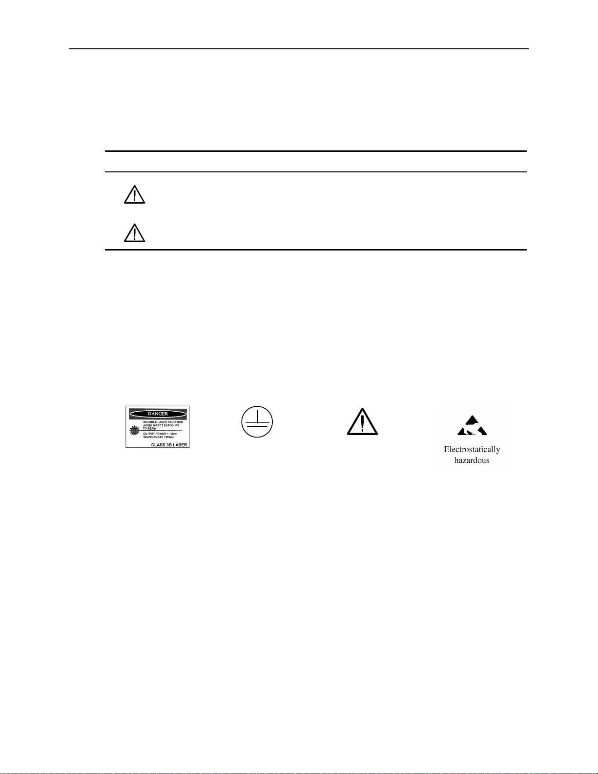
Symbols on the Product
The following symbols may appear on the product:
Refer to Manual
ATTENTION
CAUTION
Laser Radiation
Protective Ground
(Earth) Terminal
OTS9100 User Manual vii
Page 12

General Safety Summary
viii OTS9100 User Manual
Page 13

Preface
This manual describes how to use the Tektronix OTS9100 module. This manual is your primary
source of information about how the OTS9100 module functions.
The user interface also provides Windows Help files for further information on specific topics.
How This Manual is Organized
This manual is divided into four sections: Getting Started, Operating Basics, Reference, and
Appendices.
• Getting Started provides an overview of the OTS9100 module and describes first-time
operation.
• Operating Basics explains the basic principles of operating the OTS9100. The Operating
Basics section also includes sample applications.
• Reference provides a brief overview of the syntax and format used for remote commands and
provides explanations and listings of all the remote commands that may be used with the
OTS9100 system.
• The Appendices provide a listing of specifications, default factory settings, an incoming
inspection test, list of acronyms, and other useful information.
OTS9100 User Manual ix
Page 14

Preface
Conventions
This manual uses the following conventions:
The names of front-panel connectors and LEDs appear in the manual in the same format as
found on the front panel label, for example, OPTICAL IN and Rx DATA OUT.
When the user interface is discussed, all menus, names tags, and button appear in the manual
in the same format as found in the user interface, for example, Enable COM2 and Output
Pulse Trigger.
In reference to terminology, the user interface may be set to either SDH or SONET
references. The user manual provides SDH terminology with SONET terminology in
parenthesis immediately following the SDH version. If no second terminology is present, the
terminology is the same for both SDH and SONET.
In reference to the instrument, the following conventions apply:
• When referring to the four card 10Gb/s system (Optics, Transmit, Receive, and
Clock), the name OTS9100 is used.
• When referring to each individual card, the card name is used, for example, Optics
and Transmit.
NOTE: Some of the content found in this manual does not pertain to some instruments.
Depending on the software revision and the options installed, some of the features
described in these pages may not be available.
x OTS9100 User Manual
Page 15

Getting Started
This chapter describes the preparation and initial setup of the OTS9100 module. Also provided
is a list of standard and optional accessories for each of the individual cards.
Product Description
The Optical Test System OTS9100 Module set consists of a 10 Gb/s SONET/SDH transmitter
and receiver. The transmitter consists of a high-speed OC-192c/STM-64c SONET/SDH digital
signal generator feeding a 10 Gb/s fiber-coupled laser and modulator. It is capable of generating
fixed and pseudo-random test patterns mapped into a set of sub-rate payloads or one full payload
rate. The transmitter may also retransmit received 10 Gb/s signals with or without alarm and
error insertion via intrusive through mode capabilities. Both transmitter and receiver support
Unframed Mode. The transmitter supports flexible generation of alarms and errors at SONET
and SDH levels (SONET Section, Line and Path; SDH Regenerator Section, Multiplex Section
and Path).
The receiver consists of a high-speed 10 Gb/s (9.9532 Gb/s) optical receiver feeding an OC192c/STM-64c digital signal analyzer. The receiver supports both SONET and SDH (SONET
Section, Line and Path; SDH Regenerator Section, Multiplex Section and Path) alarm and error
detection and accumulation for subsequent software analysis with the ability to print out reports.
The standard OTS9100 module consists of one each of an OTS91L4, OTS91R2, OTS91T3 and
OTS91C3 card. A mixed suite of optical cards provides the OTS9100 module with flexibility to
test for different optical requirements.
The OTS91L4 Transceiver card is the standard optical card for this module. The OTS9100
module will accept any of the OTS optical cards as a replacement for the OTS91L4, expanding
the range of the system to support different types of test analysis. The only requirement is that
the optics card be placed in the first slot position within the OTS9100 module.
Optical card offerings consist of the following:
OTS91L4 Transceiver with 1550 nm or 1310 nm laser option
OTS91L5 Transmitter with 1550 nm or 1310 nm laser option
OTS91L6 Receiver Only
OTS91L7 Transceiver with External Laser Interface (does not include an internal laser)
OTS91L8 Transmit Only with External Laser Interface (does not include an internal laser)
OTS9100 User Manual 1-1
Page 16

Getting Started
OTS9100 Features and Capabilities:
• OC-192 SONET Section, Line, and Path Testing
B1, B2, B3, REI-L, REI-P and random bit Error Generation
B1, B2, B3, REI-L, REI-P Error Measurement
Section, Line, and Path Alarm Generation
J0, J1 byte and sequence Capture; J0, J1 Edit
Section, Line, and Path Alarm Detection
Section, Line, and Path Alarm and Error Generation
STS1, STS3c, STS12c, STS48c, STS192c structured payloads filled with user-selected test
pattern
• STM-64 SDH Regenerator Section and Multiplex Section Testing
B1, B2, B3, MS-REI, HP-REI, and random bit Error Generation
B1, B2, B3, MS-REI, HP-REI Error Measurement
RS, MS, and Path Alarm Generation
J0, J1 byte and sequence Capture; J0, J1 Edit
RS, MS, and Path Alarm Detection
RS, MS, and Path Layer Alarm Error Generation
VC-3, VC-4-4c, VC-4-16c, VC-4-64c structured payloads filled with user-selected test pattern
• Multi-channel capability in a single mainframe
• Available in Transceiver, Receive Only, and Transmit Only configurations
• Electrical Offset of Receiver Decision Threshold
• Windows 2000 compatible user interface
• Easily switched between SONET and SDH modes
• Through Mode with Overhead Editing, Error, and Alarm Injection
• Direct user download of software updates
• GR-253-CORE and CCITT/ITU G.708, G.709 framing
• Complete Remote Control via RS-232, GPIB, and Ethernet LAN (10BaseT) ports and scripting
available with the implementation of the OTS Toolkit
• Interface to STE, LTE and other test equipment
• High Output Power 1310 nm or 1550 nm Laser Allows Support for Multiple Receivers via an
Optical Splitter
• G.828/G.829 B1, B2 and B3 Error Analysis
• SONET (OC-192c) and SDH (STM-64c) Format Signals Supported in a Single Module
• Interchangeable Between the Rackmount, Benchtop and Portable Chassis
• Report Printout Capabilities
1-2 OTS9100 User Manual
Page 17

Getting Started
The OTS9100 meets the needs of development, manufacturing, and service engineers by providing the
capabilities for:
• System interrogation and conformance testing
• System Qualification
• Manufacturing Production Testing
• Manufacturing Test of SONET/SDH and DWDM Network equipment
• Network Integrity testing
• Network Performance monitoring
• Network Troubleshooting
• Design Verification
• DWDM Parallel Channel System Test
• Module Test
• Equipment Performance Monitoring
• In-service Monitoring
OTS9100 User Manual 1-3
Page 18

Getting Started
Accessories
Accessories included with the OTS9100 module are provided in the following list. If you wish
to purchase optional accessories contact your local Tektronix Representative.
Standard with each shipment
Certificate of Traceable Calibration
119-6364-11 OTS9000 Software CD
063-3560-03 OTS9100 User Manual CD
071-1060-03 OTS9100 Installation Guide
NOTE: DC Blocks are provided for use in two instances only. The first being, one DC Block must
always be connected to the OTS91R2 Receive Card at the Rx interface port in all OTS9100
modules (see Figure 1-3 for cabling illustration).
The second is in regard to use with the Transmit interconnection when using earlier versions of
the optics cards; the OTS91L1, OTS91L2 and the OTS91L3, the earlier optics cards will require
that a DC Block be connected to the Tx DATA OUT interface port.
DO NOT ATTACH A DC BLOCK TO THE OTS91T3 WHEN USING OTS91L4, OTS91L5,
OTS91L6, OTS91L7 OR OTS91L8, DEGRADATION WILL OCCUR.
Each of the optical cards requires a specific set of accessories. Additional items are listed by
each card type below.
OTS91L4 Standard
174-4702-00 6” coax cable (one included with shipment)
174-4277-01 8” coax cable (one included with shipment)
OTS91L5 Standard
174-4702-00 6” coax cable (one included with shipment)
OTS91L6 Standard
174-4702-00 6” coax cable (one included with shipment)
174-4277-01 8” coax cable (one included with shipment)
1-4 OTS9100 User Manual
Page 19

OTS91L7 Standard
174-4702-00 6” coax cable (two included with shipment)
174-4277-01 8” coax cable (one included with shipment)
OTS91L8 Standard
174-4702-00 6” coax cable (one included with shipment)
Note: Optical connectors require customer supplied cabling.
OTS91R2 Standard
174-4275-01 4” coax cable (one included with shipment)
Getting Started
119-6156-00 DC Block
OTS91T3 Standard
174-4275-01 4” coax cable (one included with shipment)
174-4275-01 6” coax cable (one included with shipment)
119-6156-00 DC Block
OTS91C3 Standard
174-4275-01 4” coax cable (one included with shipment)
Optional
Interface Cables, RS-232-C, GPIB:
RS-232-C
012-1379-00 9-pin female to 9-pin male
012-1298-00 9-pin female to 25-pin male
GPIB
012-0991-00 2m, double-shielded
012-0991-01 1m, double-shielded
NOTE: The GPIB cable is standard equipment with an OTS9010 mainframe.
OTS9100 User Manual 1-5
Page 20

Getting Started
Adapters, SMA:
015-0572-00 SMA male to BNC male
015-0554-00 SMA male to BNC female
015-0549-00 Male to female connector (Used permanently
installed to prolong life of instrument connector)
020-1693-00 SMA Kit
Miscellaneous:
119-5610-00 Fixed 15 dB optical attenuator; FC/PC connector
119-5970-00 Fixed 15dB optical attenuator, SC/PC connector
119-5972-00 Fixed 15dB optical attenuator, ST/PC connector
International Power Plug Options (Chassis Only)
Option # Description
A1 220V, Euro Plug
A2 240V, UK Plug
A3 240V, Aust Plug
A4 240V, North American Plug
A5 220V, Swiss Plug
A99 No power cord
1-6 OTS9100 User Manual
Page 21

First Operation
OTS9100 Installation
Before using the system, verify that it is properly set up and powered on, as follows:
1. Remove the unit from its shipping carton and place it on an anti-static surface.
2. Verify that the operating environment is within the limits detailed under the Environmental
Requirement section in this manual.
3. Allow approximately 2 inches (5 cm) clearance for cooling at the front and rear of the unit.
The fans draw air into the system from the front and exhaust the air through the rear of the
OTS9000 chassis system or through the sides of the OTS9010 and OTS9040 chassis systems.
4. If the module cards are not already installed, perform the following steps:
CAUTION! When installing and removing cards from the chassis, power must not be present.
Ensure that all power switches are in the OFF position and power cords are not installed
before removing or installing cards. The chassis does NOT support hot-swap installations.
Getting Started
A. Remove the cards from the packaging, if necessary.
CAUTION! All OTS cards are static sensitive. When handling cards, ensure that personnel
are properly grounded and OTS cards are always placed on anti-static surfaces. If proper
precautions are not taken, damage will occur.
B. For those locations in which cards are being installed, remove the blanking panels and air
diverters.
C. Verify the required configuration of cards before proceeding. Carefully install each card
into a slot in the chassis. Make sure that the card is lined up and fits cleanly with the
connectors into the backplane of the chassis.
CAUTION! Beware of bending the pins of the connectors when installing and removing cards
from the chassis. Backplane connectors with bent pins will cause damage to both the card
and the chassis.
To install the card, slowly slide the card into the desired slot. Make sure the card is lined up with
the connectors and push down on the top release and up on the bottom release until the card
snaps into place.
OTS9100 User Manual 1-7
Page 22

Getting Started
When the card is in place, tighten the two screws to secure it.
CAUTION! Do not torque the screws with more than 2 in-lbs of force or damage will occur.
5. Verify that the power switch of the OTS chassis is in the OFF position.
6. Plug the unit into the appropriate AC Power source as follows:
Table 1-4: Power Requirements
AC Voltage Voltage Range Frequency Range
110 VAC 90 VAC - 132 VAC 48 - 62 Hz
220 VAC 180 VAC - 250 VAC 48 - 62 Hz
Removing Cards
To remove the OTS cards, perform the following steps:
1. Turn off the power.
2. Fully loosen the two screws found on the top and bottom of the card.
3. Push up on the top release and down on the bottom release until the card is released from the
connectors.
4. Carefully slide the card out of the slot.
NOTE: If a card is removed, a blanking panel and air diverter must be installed to ensure
proper airflow through the system. Failure to replace the air diverter and blanking panel could
cause the system to overheat.
1-8 OTS9100 User Manual
Page 23

Slot Positioning of OTS Cards
The slot in which each card is installed is very important to the proper operation of the
instrument. Because of the user interface configurations, certain cards must be in specific slot
positions in order to take advantage of features to operate correctly.
The OTS9100 module consists of a grouping of four cards. For every OTS9100 module group,
the Optics card must be in the leftmost card or slot 1 (Does not apply to a multi-channel system).
The Optics card must be followed by the Receive card in the second position, the Transmit card
must be in the third position and the Clock Trigger card must always be in the right-most position
or fourth position within the four card module grouping.
Multiple Modules
A module group may span the CPU in a multi-module system if necessary. The sequence of
cards should continue from one side of the CPU slot(s) onto the other side. The CPU card(s) may
interrupt the sequence physically but does not end the module group. Slot positioning with the
CPU interrupting a sequence of cards will not affect the functionality of the OTS cards on either
side of the CPU slot position(s). Empty slots, or slots containing non-Tektronix cards; effectively
‘end’ the module group.
Getting Started
When an OTS9100 10 Gb/s module and an OTS9200 Jitter module are loaded within the same
chassis the slot positioning must start with the OTS9100 optical card positioned in the first
position with the rest of the OTS9100 module loading sequentially as described above, the
OTS9200 module must be adjacent to the OTS9100.
Through Mode operation is only supported when the module has been loaded into slots 1-4 of the
chassis and only when the modules are installed in the following order:
• Optics card is in slot 1
• Receive card is in slot 2
• Transmit card is in slot 3
• Clock Trigger card is in slot 4
If cards are not installed in this order, “through mode” is not allowed as a Tx Signal Source.
NOTE: If the slot positioning rules are not followed, the module functions will be invalid. The
transmitter and receiver functionality depends upon the absolute slot position and relative order
of the cards.
OTS9100 User Manual 1-9
Page 24
Getting Started
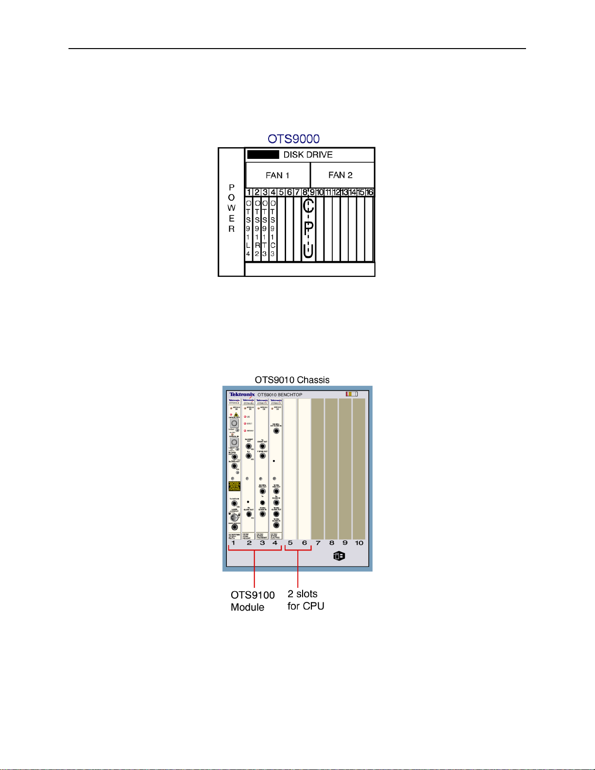
Figure 1-1: OTS9000 with card slot assignment
The slot assignments shown in Figure 1-1 show an OTS9100 module loaded into an OTS9000 chassis to
support through mode.
Figure 1-2: OTS9040 with OTS9100 installation
The slot assignments shown in Figure 1-2 show an OTS9100 module loaded into an OTS9040 chassis.
1-10 OTS9100 User Manual
Page 25

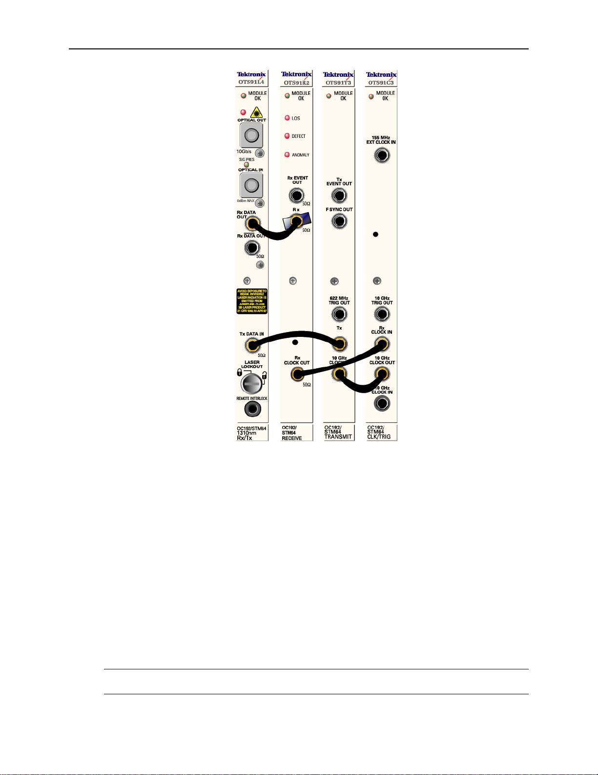
Module Card Interconnection
Before powering on the system, install the cables and DC blocks provided for signal
interconnection of the module cards. Use Figure 1-3 as a reference guide. (See Appendix G for
cabling an OTS9100 module with a tunable laser).
NOTE: Depending upon the configuration of the OTS cards within the OTS-9000, some of these
connections may not need to be made. If multiple cards are present within the system, the 8”
cables provided may be required in place of the 4” cables.
1. Attach a 4 or 6” coax cable from the Rx DATA OUT port of the Optical card. Connect the
other end of the cable to the Rx DATA IN port DC block located on the Receive card. The
Optical card is now connected to the Receive card.
2. Attach a 4 or 6” coax cable to the Tx DATA IN port of the Optics card. Connect the other
end of the 4 or 6” coax cable from the Tx DATA IN port to the Tx DATA OUT (Tx) port of
the Transmit card. The Optical card is now connected to the Transmit card.
3. For through mode only: Attach a 4 or 6” coax cable to the Rx CLOCK OUT port of the
Receive card. Connect the other end of the cable to the Rx CLOCK IN port of the Clock
Trigger card. The Receive card is now connected to the Clock Trigger card.
Getting Started
4. Attach a 4” coax cable to the 10GHz Clock In port of the Transmit card to the 10GHz Clock
Out port of the Clock Trig card. The Transmit card is now connected to the Clock Trig card.
NOTE: To install peripherals (mouse, monitor, keyboard), refer to the chassis manual.
CAUTION! Before moving previously installed cables, loosen the connections on both ends of
the cable. If one end of a cable is moved and the other end is not loosened, damage to the
cable will occur.
OTS9100 User Manual 1-11
Page 26
Getting Started
Figure 1-3: Proper location Interconnection cables
Power On and Software Initialization
1. Set the Power Switch, on the back of the chassis, to the ON position. Turn on the display
monitor. Wait for Windows to boot and present the login prompt.
2. The first time the system is turned on, a Microsoft Licensing Wizard will run, follow the
prompts and enter the Windows 2000 License Key number, operator name, password and
network identifier. The License Key number is located on a label affixed to the OTS chassis.
This utility will run only for this initial one time system launch.
3. To logon, press CNTL-ALT+DEL.
4. The logon information dialog box is now displayed. Verify that the user name is
‘Administrator’ and there is no password then click OK.
5. To launch the system application, click the OTS9000 icon on the desktop.
NOTE: The OTS9000 application may also be reached through the START menu. Click START,
select Tektronix, then select OTS9000.
1-12 OTS9100 User Manual
Page 27

Module Quick Check
NOTE: Before installing the optical cables, clean the optical fiber connectors on both the cable
ends and the front panel connectors.
1. With proper in-line 15dB attenuator, connect a single mode optical cable between the Optical
OUT and Optical IN connectors on the Optics card.
CAUTION! Signal levels greater than 0 dBm may damage the Optical Input devices. Always
pad the input level to less than 0 dBm.
Always use 15dBm of attenuation when connecting the OTS9100 module transmit output to its
receive input. Failure to do so will damage the optical detector.
2. If the instrument is not already powered on, start the system as described in the Power On
and Software Initialization procedure of the previous section.
3. From the Menu Bar, click the System button; this opens a drop down menu. In the drop down
menu select Signal Standard then select Set to SONET.
4. Transmitter Setup
From the Menu Bar, click on View and select System View. The System View should
display an image with each card in position. Check this view to ensure that all the cards
loaded are visible. Blue lines spanning across the cards represent the correct cabling for the
configuration of cards loaded in the system. The System View window is meant to be used as
a reference for verifying cards and cabling a system. It does not provide a means to
determine live or dead cards.
Getting Started
5. Click the Setup Category bar in the Navigation window and select the OTS91T3 10Gb/s Tx+
#1 icon. The Setup Property Page associated with the selected icon should display.
6. In the Property Page window, select the Signal tab and make the following selections from
the pull-down menus:
• Signal Source: Internal
• Timing Source: Internal
• Trigger Output: Anomaly
• Active Channel, Signal Structure: STS-1
• Active Channel, Test Pattern: PRBS 2^23-1 (ITU)
• Active Channel, 1
7. Select the Error Insertion tab and make the following selections:
• Anomaly Insertion Setup Type: None
• Defect Insertion Setup Type: None
8. Receiver Setup
In the Navigation window, keeping the Setup Category as the active category (always check
the Title Bar of the Setup Menu to ensure that it is associated with the correct device), select
the OTS91R2 10Gb/s Rx+ #1 icon and set the Receiver Threshold Offset level to 0 mV.
9. In the Navigation window, click on the Test Control Category bar and select the OTS91R2
10Gb/s Rx+ #1 icon.
10. Click the Edit Test Control Settings.
OTS9100 User Manual 1-13
Page 28

Getting Started
11. Click the radio button for Continuous test mode and then click OK to close the dialog box.
12. Use the key provided to disable the laser lockout at the front of the Optical card.
13. On the Laser Control bar, select the OTS91T3 10Gb/s Tx+ #1 laser and click On. On the
Optics module card front panel, verify the following:
14. On the Test Control bar, click the start button to begin a test.
15. On the front panel of the Receive module card, verify that the LOS, DEFECT, and
ANOMALY LEDs are all off.
16. Verify that the Status window has no lit error indicators except the green Signal Present
indicator.
17. In the Navigation window, click the Setup bar and select the OTS91T3 10Gb/s Tx+ #1 icon.
18. Select the Error Insertion tab.
19. Under Anomaly Insertion Setup, click the pull-down menu for Type and select B1 BIP.
20. Click Apply Anomaly Setup Changes.
• the Optical Out LED lights green
• the Sig Pres LED under Optical IN lights green
21. Click Insert Single three times to insert three single errors. Verify that the Anomaly LED on
the Receive front panel flashes for each B1 injected. In the Status window, the red B1
indicator should flash for each B1 injected and the yellow B1 indicator should remain lit.
22. In the Navigation window, click Measurements and select the OTS91T3 10Gb/s Rx+ #1
icon.
23. Click on the Cumulative tab.
24. Verify that the B1 line has data entered.
25. On the Test Control bar, click the Stop Test button.
26. On the Laser Control bar, select the OTS91T3 10Gb/s Tx+ #1 laser and click Off.
27. Use the key provided to enable the laser lockout.
1-14 OTS9100 User Manual
Page 29

Emergency Startup Disk
Instructions for creating an emergency startup disk can be found in Appendix D. It is
recommended that you take the time to do this simple procedure every time you change your
system configuration.
Shutdown and Power Off
If necessary, it is considered safe to shut off power without prior shutdown steps. However, it is
strongly suggested that a more orderly shutdown be followed. To perform an orderly shutdown,
use the following steps:
1. Close the OTS9000 application by selecting Exit under the System menu.
2. From the Start button on the Windows 2000 Taskbar, choose Shut Down.
3. On the Shutdown dialog box, choose Shut down the computer and click Yes.
4. When the Windows 2000 message ‘It is now safe to turn off your computer’ appears, turn off
power.
Getting Started
OTS9100 User Manual 1-15
Page 30
Module Operating Basics
This section describes the OTS9100 module front panel indicators and connectors.
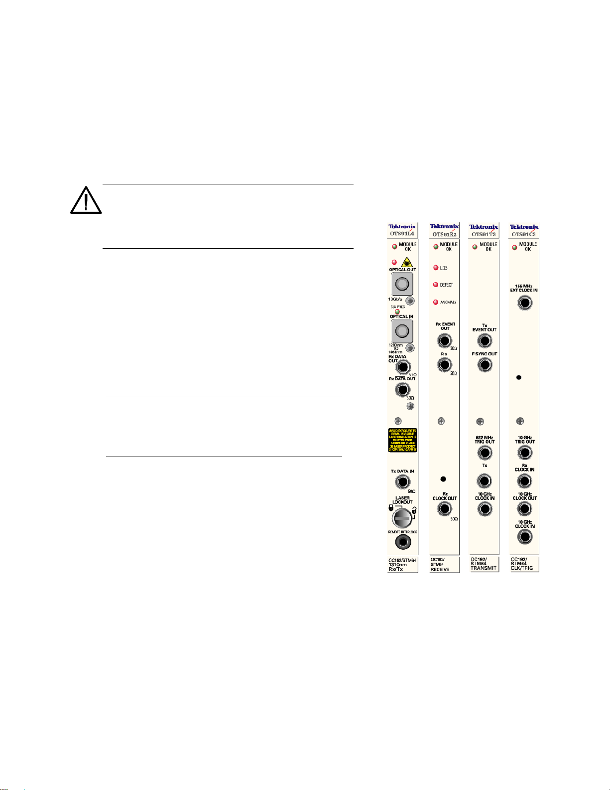
Front Panel Indicators and Connectors
Figure 2-1 shows a complete view of the front panel.
WARNING: Always avoid exposure to the laser beam.
Before power is applied to the OTS9100 module be
sure that all laser outputs are either covered with the
screw cap provided or connected to the appropriate
circuit.
The front panel is made up of four different cards:
• Optics
• Transmit
• Receive
• Clock Trigger
The following sections describe each of these cards
in more detail.
NOTE: There are several versions of the optical card
available. Each OTS91Lx series card has been
designed with targeted analysis capabilities directed
at specific analysis needs. For additional information
on each OTS91Lx series card see Appendix A.
Figure 2-1: OTS9100 Front Panel
OTS9100 User Manual 2-1
Page 31

Operating Basics: Functional Overview
10Gb/s Transceiver Optics
The 10Gb/s Transceiver is available with two laser options, 1310
nm and 1550 nm. The 1310 nm Optical Transceiver consists of a
1310 nm Transmitter combined with a broad band Receiver. The
1550 nm Optical Transceiver consists of a 1550 nm Transmitter
combined with a broad band Receiver
Figure 2-2 shows the Transceive card with 1310 nm laser front
panel.
The front panel of the Transceiver card has optical inputs and
outputs, a laser lockout feature, and LED monitoring lights. Each
of these items is described in more detail below.
Module OK
The Module OK LED should be green while the instrument is
running. On power up, the LED first lights red, then will switch to
green when the system has finished initializing.
NOTE: If the LED remains red after the system has finished
initializing, call Tektronix for service.
The Optics Transceiver card of the OTS9100 module provides
all of the optical interfaces of the 10Gb/s SDH/SONET module.
Figure 2-2 shows the Optic Transceiver card front panel.
WARNING: Always avoid exposure to the laser beam. Before
power is applied to the OTS9100 module be sure that all laser
outputs are either covered with the screw cap provided or
connected to the appropriate circuit. Keeping a laser output covered
prevents dirt from contaminating the connector.
Optical OUT
The Optical Output transmits an optical data signal at a
wavelength of 1310 nm or 1550 nm, with the proper installed
option. The optical connector can be configured with field
interchangeable shells: FC (standard), ST, or SC type. The field
interchangeable shells are easily removed to allow cleaning of the
optical connector interface.
The LED found under Optical OUT will light to green when the
laser is active.
Figure 2-2: 1310 nm
Transceiver Front Panel
NOTE: If the LED lights red or fails to light at all, call Tektronix for
service.
2-2 OTS9100 User Manual
Page 32

Optical IN
The Optical IN connection accepts the incoming optical signal to
the receiver. This input signal must have a wavelength between
1290 nm and 1565 nm and must not exceed –0 dBm of power.
The green LED labeled SIG PRES under the Optical IN heading
will light when the Optics card detects an incoming signal. Red
flashing indicates an optical loss condition. An amber flashing
LED indicates an optical overload condition.
WARNING: The incoming signal must be attenuated to within
specified power levels. If the signal exceeds –0 dBm, damage may
occur.
Rx DATA OUT
Rx DATA OUT provides signal interconnection between the
module cards. This output must be connected to the Rx DATA IN
connection found on the Receive card of the OTS9100 module
using the coax cable and DC block provided.
Operating Basics: Functional Overview
Rx DATA OUT
Rx DATA OUT is a 10 Gb/s DATA Signal provided for jitter
measurements. This signal must be connected to the 10 Gb/s
DATA IN connector of the OTS92H1 Clock Receive card.
Tx Data IN
Tx Data Input provides signal interconnection between the module
cards. This input must be connected to the Tx Data Out
connection found on the Transmit card of the OTS9100 module
using the coax cable provided.
WARNING: Always avoid exposure to the laser beam. Before power
is applied to the OTS9100 module be sure that all laser outputs
are either covered with the screw cap provided or connected to the
appropriate circuit.
Figure 2-3:
1550 nm Transceiver
Front Panel
OTS-9100 User Manual 2-3
Page 33

Operating Basics: Functional Overview
Laser Lockout, Remote Interlock
REMOTE INTERLOCK is a bantam plug normally closed connection internally wired in series
with the laser lockout key switch. It can be used with additional hardware to remotely disable
the laser output.
NOTE: If this connection is used, the ferrite bead provided with the module must be attached to
the remote interlock cable for lower emissions and CE mark conformance. Install the bead close
to the end of the cable connected to the Optics card.
Laser LOCKOUT is a safety device. The key switch disables the laser output when it is turned
to the “closed lock” position. The laser output can only be turned on when the key is in the
“open lock” position.
NOTE: The laser output cannot be enabled unless:
• The Laser Lockout key switch is set to the “open lock” or on position.
• The Remote Interlock is either not used or externally enabled.
• The Laser output is software enabled.
NOTE: Optical cables use and care
1. When using the optical cables ensure that the cable is firmly seated in the front panel
connector. The optical connectors on the front panel are keyed. If the cable is not inserted
into the connector key properly, the connection between cable and front panel will not be
complete and so will cause errors in transmission and receiver functions.
2. Always be sure to clean both cable connectors and front panel connectors before installing
optical cables. A dirty optical connection can cause errors in transmission and receiver
functions.
2-4 OTS9100 User Manual
Page 34

Receive Analysis
The Receive card contains the receiver SDH/SONET signal
analysis functionality for the OTS9100 10Gb/s SDH/SONET
module.
Figure 2-4 shows the Receive card front panel.
Module OK
The Module OK LED should be green while the instrument is
running. On power up, the LED first lights red, then will switch
to yellow, and finally to green when the system has finished
initializing.
NOTE: If the LED remains red after the system has finished
initializing, call Tektronix for service.
Operating Basics: Functional Overview
LOS
The LOS (Loss of Signal) LED indicator can be off, red, or
yellow. This indicator will turn red when the receiver detects a
Loss-of-signal condition. Once the receiver regains the signal,
the LOS indicator will turn to yellow and remain yellow until a
new test is started, the module is powered off, or the receiver
detects another Loss-of-signal condition.
A yellow history indicator signifies that LOS has occurred since
the most recent test started, but is not currently detected.
The LOS indicator will turn off when a new test is started.
DEFECT
The Defect indicator can be off, red, or yellow. This indicator
will turn red when a defect (no signal present, LOS, LOF, OOF
(SEF), MS-AIS (AIS-L), MS-RDI (RDI-L), LOP, AIS-P, or
RDI-P) is detected. It will flash red if defects are detected
intermittently.
A yellow history indicator signifies that a Defect has been
detected since the most recent test started, but is not currently
detected.
The Defect indicator will turn off when a new test is started.
OTS9100 User Manual 2-5
Figure 2-4: Receive
Front Panel
Page 35

Operating Basics: Functional Overview
ANOMALY
The Anomaly indicator can be off, red, or yellow. This indicator will turn red if an anomaly (B1,
B2, REI-L, B3, FAS, REI-P, or payload error) is detected. It will flash red if an anomaly is
detected intermittently.
A yellow history indicator signifies that an Anomaly has been detected since the most recent test
started, but is not currently detected.
The Anomaly indicator will turn off when a new test is started.
Rx Event OUT
The Rx Event Output is user activated and provides an active HIGH for each alarm or error
condition generated. The output will provide a single pulse for each frame containing errors. It
can be used as a means of triggering an oscilloscope or other test equipment. The output has an
SMA connector and requires 50 termination for signal integrity.
Rx Data IN
The Rx Data Input provides signal interconnection between the module cards. This input must
be connected to the Rx DATA OUT connection found on the Optics card of the OTS9100
module using the coax cable and DC block provided.
Rx Clock OUT
The Rx Clock Output provides signal interconnection between the module cards. This output
must be connected to the Rx Clock Input found on the Clock Trigger card of the OTS9100
module using the coax cable provided.
2-6 OTS9100 User Manual
Page 36

Transmit Generation
The Transmit card of the OTS9100 module contains all of the
transmitter functionality for the 10Gb/s SDH/SONET module.
Figure 2-5 shows the Transmit card front panel.
Module OK
The Module OK LED should be green while the instrument is
running. On power up, the LED first lights red, then will switch
to green when the system has finished initializing.
The LED will flash YELLOW if one or more internal clock
circuits can not lock to the 10GHz clock input. This condition
occurs when the input clock is not within specified frequency
range.
Note: If the LED flashes Yellow, the 10 GHz input clock is
missing or out of range. If the LED remains red after the
system has finished initializing, call Tektronix for service.
Operating Basics: Functional Overview
Tx EVENT OUT
The Tx Event Output is user activated and provides an active
HIGH for each alarm or error condition generated. The output
will provide a single pulse for each frame containing errors. It
can be used as a means of triggering an oscilloscope or other test
equipment. The output has an SMA connector and requires 50
Ohms termination for signal integrity.
F-SYNC OUT
The Frame Synchronization Output provides a signal that is
asserted to indicate the start of a frame. It may be used as a
means of triggering an oscilloscope to capture the 10Gb/s Optical
Output signal. The output has an SMA connector and requires 50
Ohms termination for signal integrity.
Figure 2-5:
Transmit Front Panel
OTS9100 User Manual 2-7
Page 37

Operating Basics: Functional Overview
622 MHz TRIG OUT
The 622 MHz TRIG OUT provide a bit-rate/16 signal that may be
used for triggering an oscilloscope to capture the 10 Gb/s Output
signal. The output has an SMA connector and requires 50 Ohms
termination for signal integrity.
Tx DATA OUT
Tx Data Output provides a DC-coupled CML output signal for
interconnection between the module cards. This output must be
connected to the Tx DATA IN connection found on the Optics
card of the OTS9100 module using the coax cable provided.
Note: When connecting to an OTS91L1 card, a DC block
must also be installed.
10 GHz CLOCK IN
The 10 GHz Clock IN is the bit-rate clock for the Tx Data Out
interface. This input must be connected to the 10 GHz Clock Out
port of the Clock Trigger card using the coax cable provided.
2-8 OTS9100 User Manual
Page 38

Clock Trigger
The Clock Trigger card provides the reference clock sources
for the transmitter and receiver functions of the 10 Gb/s
SDH/SONET module.
Figure 2-6 shows the Clock Trigger card front panel.
Module OK
The Module OK LED should be green while the instrument is
running. On power up, the LED first lights red, then will switch
to green when the system has finished initializing.
The LED will flash YELLOW if the clock’s multiplier can not
lock to the selected reference input. This condition occurs when
the input clock is not within specified frequency range.
Note: If the LED flashes Yellow, the 10 GHz input clock is
missing or out of range. If the LED remains red after the
system has finished initializing, call Tektronix for service.
Operating Basics: Functional Overview
155 MHz EXTERNAL CLOCK IN
The External Clock Input accepts a 155 MHz clock signal which
can be used to offset the transmit signal. The input has an SMA
connector and 50 Ohms termination.
10 GHz TRIG OUT
The 10 GHz Trigger Output provides a bit-rate signal that may
be used for triggering an oscilloscope to capture the 10 Gb/s
Output signal. The output has an SMA connector and requires
50 Ohms termination for signal integrity.
Rx CLOCK IN
The Rx Clock Input provides signal interconnection between the
module cards. This input must be connected to the Rx Clock
Output found on the Receive card of the OTS9100 module using
the coax cable provided.
Figure 2-6:
Clock Trigger Front
Panel
OTS9100 User Manual 2-9
Page 39

Operating Basics: Functional Overview
10 GHz Clock Out
This output is connected to the OTS91T3 card using the coax cable provided.
10 GHz CLOCK IN
The 10 GHz Clock IN provides a bit-rate clock input that typically is connected to the OTS92H1
10 GHz JITTER Clock Out port. This input is selected when Transmit Timing is set to “Jitter”.
2-10 OTS9100 User Manual
Page 40

Operating Basics: User Interface
Software Interface Operating Basics
This section describes the OTS9000 software interface. It also reviews the basic functionality of
the Microsoft Windows application software with menu descriptions.
User Interface
The user interface software for the OTS Family Optical Test System controls all configuration,
testing, and measuring commands of the OTS cards. The user interface provides easily navigated
menus using Windows® ‘point and click’ operation on a Windows 2000 workstation.
Refer to the section, Getting Started, for information on how to load and launch the user
interface software.
When the OTS Optical Test System is first powered on the software scans the card slots to
determine what modules are loaded. The user interface then provides icons in the navigation
window for each card loaded into the system. These icons always reflect the cards loaded and
will change depending on the system being used. Because of this ‘on the fly’ software feature,
some of the menus and abilities described in this manual may not be available in all systems
since many features require a particular card installation. In addition, some of the menu screens
may appear different from those displayed in this manual.
The user interface screen has a number of windows and bars that comprise the main screens of
the software, some of which may be disabled. The next section, Elements of the User Interface,
identifies each element on the main screen. The sections following it provide supporting
descriptions for each of these elements.
NOTE: The user interface is a Microsoft Windows 2000 application. Information
regarding standard Windows 2000 functions is beyond the scope of this document. For
further information on basic commands and functions of Windows 2000, refer to the
Windows 2000 manual.
OTS9100 User Manual 2-11
Page 41

Operating Basics: User Interface
A
ar
w
Elements of the User Interface
The user interface has a number of windows and bars that comprise the main screens of the
software. Figure 2-6 identifies each of these elements. The Navigation Window, Test, Laser
Control bars, and Status Windows may be disabled for more viewing space, if desired.
Active Task Bar
Menu Bar
Tool B
Frame
Grabbers
Scroll Controls
for extended
Navigation
(a dockable
Navigation
Windo
floating
window)
Laser Control bar
Test Control bar
Current, Activated Card
Clear History
Control
Scroll Rocker
Control
Card Slot
Selection
Drop Down
Menu
ctive LED
Tool Bar
Window
(a dockable
floating
window)
Category
Title
Bars for
each
Property Pages
Status bar indicators
Figure 2-6:
Location of Status and Navigation Windows displayed in a Single Mode View
2-12 OTS9100 User Manual
Page 42
Task Bar
The Task bar reflects the active device and function. When a device is selected from the
Navigation window the identification of that device will appear in the Task bar. The window
controls for the Tektronix interface can be accessed by using these selections they include,
restore, minimize, maximize and close.
Menu Bar
The Menu provides the access to System controls and
functions, Views, Device controls and functions, Window
and Help functions. The Menu bar contains the control
menus for System, View, Device, Window and Help. The
Menu Bar controls can also be accessed by clicking on the
buttons found in the Tool Bar that correspond. The
corresponding button is shown beside each menu selection.
Operating Basics: User Interface
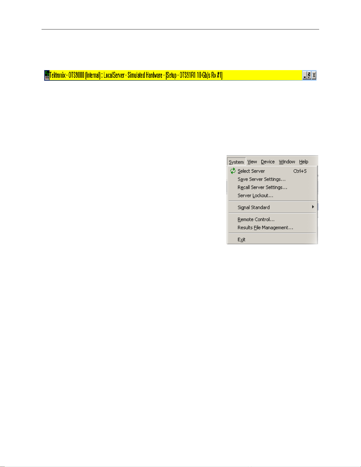
System
The System menu provides the user with access to system
level functions. The functions accessed through the System
selection are Select Server, Save Server Settings, Recall
Server Settings, Server Lockout, Signal Standard (choose SONET or SDH), Remote
Control, Results File Management and Exit.
View
The View menu allows the user to control which toolbars will be activated in the working
window framework. The functions accessed through the View selection are Navigation Window,
Tool Bar, LED window, LED Panel, Laser Control Bar, Test Control Bar, SCPI, System View,
Test Results Files, Toolbars and Options.
Device
The Device menu access the controls used for the selected device. The controls used for the
device are Setup, Signal Monitor, Test Control, Measurements, Analysis, APS Measurements
and Compliance.
OTS9100 User Manual 2-13
Page 43

Operating Basics: User Interface
Window
The Window menu provides the ability to setup how the menus are displayed within the OTS
workspace. It is possible to set the display to a single window or multiple menu windows through
this menu. Display functions include Single Mode (displaying one window at a time) and
Multiple Mode (displaying many windows simultaneously).
Single Mode
Single Mode displays one active window, full size, with no visible representation for other
properties. Exit the Single Mode display by deselecting the check box for Single Mode from the
Menu bar. Deselecting Single Mode enables other Window options.
Multiple Mode
To get a multiple window display, more than one window at a time, select Cascade, Tile
Horizontally, Tile Vertically. To enable this feature Multiple functions must be active. Setup
displays the active device setup menu.
Figure 2-6:
Multiple Window Mode View
Help
The Help menu provides a means of accessing more information on the product, on the system
and on the company. The menu consists of Help Topics (OTS Product Family Help System),
System Info (clipboard indicating which modules are installed), Remote Commands (key word
search field) and About Tektronix (license and version).
2-14 OTS9100 User Manual
Page 44
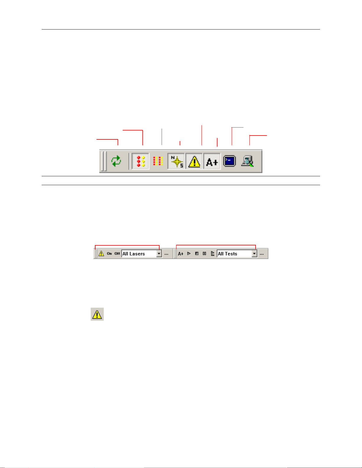
Tool Bar
The toolbar provides easy access to different views and selections of the user interface. The
buttons on the toolbar provide a toggle between select server, the LED window, the module LED
panel, the system view, the Navigation window, the laser and test control bars, and the SCPI
output. Each of these controls is discussed in further detail in later sections. The Test Control bar
may be activated via the View menu or from the toggle key on the toolbar.
SELECT
SERVER
NOTE: Changing parameters while a test is in progress may cause invalid errors.
LED PANEL
LED MODULES
NAVIGATION
LASER
TEST
Operating Basics: User Interface
SCPI
SYSTEM
Laser Control Bar
The Laser Control bar provides the user with software control over the laser. Use the pull down
menu to select which laser to activate or deactivate. Click the On button to turn on the selected
laser. Click the Off button to turn off the selected laser.
Click the
button is clicked, the Setup Summary is displayed.
Laser Control bar
button to close the bar or use the View menu to activate the bar. When the “…”
Test Control Bar
OTS9100 User Manual 2-15
Page 45

Operating Basics: User Interface
Test Control Bar
The Test Control bar provides the controls to start, stop, pause, and continue the test. If multiple
cards are present, the test control bar also allows the user to choose the specific card under test
by use of the pull down menu. The Test Control bar may be activated via the View menu or
from the
toggle button on the toolbar.
NOTE: Changing parameters while a test is in progress may cause invalid errors.
Main Status Bar
Client Lockout
Jitter Status
Indicator
Error Status
Indicator
Test Status
Indicator
Laser Status
Indicator
The main status bar, provides a summary status all active modules, these could include laser, test,
error insertion, optical and jitter transmit states of all modules. Whether a status button displays
on the status bar or not is dependent upon the configuration of the loaded OTS cards. Each
button has to states, an On or Active state and an OFF or Inactive state.
Client Lockout
The user interface has the ability to lockout other users from setting parameters. To set the
lockout control, double click the box to the left of the main status bar (if this feature is in an
inactive state the box will be an empty gray square). The Lockout Control dialog box will be
displayed. Click the desired button and then click OK to return to the main screen. When the
lockout is in effect, a lock symbol will appear in the box by the main status bar. To unlock the
server, use the same procedure.
When one client has locked out others, the lockout indicator
tries to change a configuration parameter while locked out, a warning dialog will be displayed.
The lockout control dialog box may also be accessed by selecting Server Lockout from the
System menu.
Jitter
If jitter is generated the Jitter Inactive status box will change color and change from Jitter
Inactive to active. If no jitter is being generated the Jitter Inactive message is displayed on a
background of gray.
will be displayed. If an operator
Error
If an error insertion rate is active, the status bar will change color and change from Error Inactive
to Error Active. If no errors are being created the Error Inactive message is displayed on a
background of gray.
2-16 OTS9100 User Manual
Page 46

Test
If a test is active in any module in the system, the status bar will change color and the Test
Inactive message will change to Test Active. If no test is being conducted the Test Inactive
message is displayed on a background of gray.
Laser Off
If any laser is active in the system, the status bar will change from Laser Off to a Laser On
warning. If the laser is not in use the Laser Off message is displayed on a background of gray.
Frame Grabbers
Frame Grabbers indicate that a window within the interface is dockable or will float. They can be
vertical or horizontal, each bar representing a window. Double click on the button containing the
bars and the window will detach from its location. To reattach the window, drag it back to that
location.
Operating Basics: User Interface
OTS9100 User Manual 2-17
Page 47

Operating Basics: User Interface
LIN
E
LED Window
Activating the LED Status window provides the user with a virtual
LED status panel for the OTS9100 receiver(s), as shown in
Figure 2-7. The virtual indicators found on this window
provide error conditions, both current and historical, for
all traditional receiver error LEDs. The LED Status window
may be activated through the View menu or from the toggle key
on the toolbar.
Each condition has two separate indicators, the one on the right
is the Current condition and the indicator on the left is the
History. The Current indicators will turn red and the History
indicators will turn yellow if an error condition currently exists.
Once the condition has been removed, the red Current indicator
will turn off. The yellow History indicator will remain on until a
new test has been started or until the Clear History button is clicked.
See Table 2-1 for a description of each indicator.
AGGREGATE
SIGNAL
S
E
C
T
I
O
N
Note: Extended Panel information can be viewed with
scrolling LED bars, this feature is only enabled when a panel
P
A
T
H
is extended beyond the framework.
Three LED panel views can be enabled from within the OTS9000
application, the Module Summary Panel, the Slot Signal Panel and
the User Customizable Signal Panel.
Note: The LED panels display Receiver information only.
When only one receiver has been selected from the navigation
bar no user selectable signals will be available.
Click on the drop down menu for the LED panel to access the possible choices for the LED
panel. Each selection provides specific controls for the active LED. The choices are Module
Signal, Slot Signal and User Selected Signal. Each state is described below.
2-18 OTS9100 User Manual
Page 48

Module Signal Summary LED Panel
The summary of signal states for an individual panel. The Module Signal
Summary LED Panel provides a summary status of error signals for the
active panel.
Slot Signal LED Panel
Selecting the Slot Signal will display the LEDs for the chosen card slot.
User Selected Signal LED Window
The User Selected panel displays the results of a “User defined” state.
The user can select specific cards and display the LED states for all cards
selected. Multiple LED panel readings are aggregated into one uniform
panel display. For example, an LOS LED will be lit or “ON” if even one
out of a grouping of three cards has a loss of signal. If all three cards have no LOS then the LOS
LED would be “OFF” or not lit.
A fourth panel titled Select Signals to OR…provides access to the User Selected panel. Choosing
Select Signals to OR from the drop down menu launches a Customizable User LED Panel menu.
Three Entry Fields are contained within the menu, Panel Title Line 1, Panel Title Line 2 and a
list of active cards with check boxes.
Operating Basics: User Interface
Panel Title Line 1: Enter the name or title to be assigned to a user defined test group.
Panel Title Line 2: Enter the name or title to be assigned to a user defined test group.
Select Signal Panel Combinations provides a listing of all available Receiver cards. Choose a
combination of cards by clicking in the boxes adjacent to the card titles to select (check) or
deselect (uncheck) each available card. The User Defined Panel displays the results of these
selections.
Clear History
The Clear History button is used to clear the current history. History will begin resampling data
starting from the point in time that it was cleared.
OTS9100 User Manual 2-19
Page 49

Operating Basics: User Interface
Module LED Panel
The module LED panel operates like the LED Window. This panel is accessed via the View
menu. It may also be toggled from the tool bar. To make the panel always remain on top of the
Windows screen, check the box marked ‘Always on top’.
There are two differences between the LED Window and the module LED panel. The module
LED panel does not provide the LED display options; all LEDs are always displayed. In
addition, in the module LED panel mode, all receiver LED panels are shown. In the example in
Figure 2-8, there are four receiver cards loaded, an OTS91R2, OTS93R1, OTS92R1, OTS91R1
and one synchronization card the OTS92S1. Observe that the LEDs shown are different for each
card.
NOTE: For each card, the user interface only displays the options available for that
card. If the options are not displayed, then the option is not available for that particular
card. This view does not display the Module Summary or the User Definable panels.
Figure 2.7. The LED Module Display
2-20 OTS9100 User Manual
Page 50

Operating Basics: User Interface
Table 2-1: Description of Status Window Virtual LED Indicators
LED name Description
Signal Present The Signal indicator will light green when the receiver senses an incoming signal.
LOS The Loss of Signal indicator is activated when a LOS condition has been detected.
LOF
SEF (OOF)
FAS The Frame Alignment Sequence indicator activates when errors have been detected in the
B1 The B1 indicator will activate when SDH Regenerator (SONET Section) parity errors have
TIM-S (RS TIM) The TIM indicator activates when a J0 trace is received that does not match the expected trace.
AIS-L (MS AIS) The AIS indicator activates when the overhead and SPE are set to all ones for a user-selected
B2 The B2 indicator activates when SDH Multiplex Section (SONET Line) parity errors have been
RDI-L (MS RDI) The RDI indicator activates when bits 6, 7, and 8, of the K2 byte have been a binary 110,
MS REI (REI-L) The REI indicator activates when a non-zero value in the M1 byte is detected.
AIS-P (AU-AIS) The Path AIS indicator activates when the pointer is set to hex 3FF for five consecutive frames.
LOP-P (AULOP)
B3 The B3 indicator activates when Path parity errors have been detected.
RDI-P (HP-RDI) The RDI indicator activates when bits 5, 6, and 7 of the K3 byte have been a binary 1xx,
REI-P (HP-REI) The Path REI indicator activates when bits 1-4 of G1 are decimal values between one and
TIM-P (HP-TIM) The TIM indicator activates when a J1 trace is received that does not match the expected trace.
UNEQ-P (HPUNEQ)
PLM-P (HPPLM)
LSS The Loss of Sequence indicator activates if BER is greater than or equal to 0.20 during an
Bit Error (TSE) The Test Sequence Error indicator activates when a bit error occurs in the payload.
The Loss of Frame indicator is activated when a Loss of frame condition has occurred.
The Severely Errored Frame (Out of Frame) indicator is activated when an Out of frame
condition has occurred.
A1/A2 framing bytes.
occurred.
time.
detected.
respectively, for five or more consecutive frames.
The LOP (Loss of Pointer) indicator is activated when a Loss of Pointer condition has occurred.
A LOP condition exists when ten consecutive pointer errors are received.
respectively.
eight.
The trace setup is explained later in this section.
The unequipped path indicator activates when C2 equals zero.
The Path Label Mismatch occurs when the received C2 does not match the expected C2.
interval of one second or if the test sequence and reference sequence are out of phase.
OTS9100 User Manual 2-21
Page 51

Operating Basics: User Interface
LED Display Selection
The LED indicators displayed in the LED window reflect the status of each OTS receiver loaded
in the system. Choices may be made by using the pull down menu to select each individual slot, a
Module Summary, or User Selected Signals. Figure 2-9 reflects the LED Window for each of the
LED Display selections.
If Select Signals to OR is selected a menu with a check box list displays. Choices made in this
menu determine what the User Selected Signals will display. Two user defined fields are
provided as a means to label different test names.
The User Selected Signals display reflects all the user defined selections made in the Select
Signals to OR… check box.
Module Summary displays a generalized summarization of all LED states of each individual slot.
Selecting an individual slot from the drop down menu causes all the LEDs associated with the
selected card slot to display. Only the status of the selected slot will be displayed.
Select Signal User Selected Signal Slot Signal Module Summary
(default view)
Figure 2-9: LED Display selection options
2-22 OTS9100 User Manual
Page 52

Navigation Window
The Navigation window provides the ability to set up, monitor and
test the module, and to view the test results. The Navigation window
can be displayed via two methods, by category or by device. Set the
display window by selecting View>Options from the File Menu bar.
A choice of, by Category or By Device, is provided under the
Navigation Mode column in this window.
The Navigation window contains categories representing Setup,
Signal, Monitor, Test control, Measurements, Analysis, APS
measurement and Compliance. It displays each of the OTS cards
loaded in the system with an associated device icon. Each category
provides additional configuration and control options for the selected
OTS card.
When selected each Category bar moves to the top of the Navigation
window, reflecting the current selection. If a new icon is not selected
from the new navigation view, the menu will still reflect the previous
Navigation window selection. For example, the Navigation window
may show the Signal Monitor icons, when the currently selected
menu is actually Setup-OTS91T2 10Gb/s Tx #1.
Operating Basics: User Interface
The Navigation bar is adaptive. Entries are added depending on the
system configuration. When the server connection is established, the
user interface automatically scans for loaded hardware and displays
the appropriate folders and icons for the hardware on that server.
For example, the sample screen, reflects three transmitters
(OTS91T1, OTS91T3 and OTS92T1), two receivers (OTS91R2 and
OTS92R1) and one synchronization card (OTS92S1). Each card is
represented with a separate icon. Multiple icons of the same type
provide the same screens, but contain custom controls for each
specific card.
Note: Pay attention to the relationship between the icon selected in the Navigation
window to the Active Title Bar.
When changing screen controls by clicking on a category title in the Navigation window, ensure
that the correct device is still currently activated. A new device icon in the Navigation window
must be clicked to change the associated screen menu.
Category View Device View
OTS9100 User Manual 2-23
Page 53

Operating Basics: User Interface
Scroll Buttons
The scroll buttons are part of the Navigation window. They provide scroll
support for accessing any card icons that are beyond the immediate viewable
area of the Navigation window frame.
Note: The Navigation window is a dockable window. Double click on the
horizontal grabbers at the top of the window frame to undock the window
and float it within the OTS interface. To redock or return the floating
Navigation window, click and drag it back to the original location, where it
will be repositioned in its original frame.
Summary Icons
Every device has an associated summary represented by a summary icon within
the Navigation Window. Double click on each summary icon for each device
activated to view the
2-24 OTS9100 User Manual
Page 54

p
Setup Property Menus
When SETUP is selected from the Navigation window by clicking on the SETUP Title bar, icons
for all loaded Transmitter and Receiver cards, in addition to a summary menu, are displayed.
The Setup Property menus provide separate configuration control over each transmitter or
receiver function.
Each Receiver and Transmitter card has a setup menu that pertains to it. If an Receiver (Rx) icon
is clicked, the Receiver setup menu is displayed for the Rx card it relates to. If a Tx icon is
clicked, the Transmitter setup menu is displayed for the selected transmitter icon.
The transmit and receive setup menus may contain multiple menu screens; each selected by a tab.
Each tab represents a category of functionality specific to the transmitter or receiver setup. Every
card has a setup menu that pertains to it.
3. Note the Active Card Title Bar
1. Click on
Setu
Operating Basics: User Interface
2. Click on
the icon
Note: Scroll bars at the bottom and to the right-hand side of the Setup Window allow the
user to scroll when menu information extends beyond the window frame.
OTS9100 User Manual 2-25
Page 55

Operating Basics: User Interface
Transmitter – Signal
The Signal Property menu of the Transmitter setup, as shown in Figure 2-10, provides the
controls for selecting the Signal setup, Transport overhead, Path overhead, Error insertion, K1,
K2 Decode, IP payload and IP error. In addition, the signal structure and test pattern for both the
active channels and the background channels are configured on this setup menu. Each of the
selections available is described in more detail in the following sections.
Figure 2-10: Transmitter Setup – Signal menu
Signal Standard
Signal Standard selects the operating mode of the transmitter. To select either SONET or SDH
mode, click on the pull-down menu and select the desired operating mode. The operating mode
may also be selected via the menu bar. Click on System – Signal Standard and select either Set
to SONET or Set to SDH.
NOTE: If the signal standard is selected via the menu bar (View>Options), the signal standard is
set for all devices in the system.
2-26 OTS9100 User Manual
Page 56

Operating Basics: User Interface
BERT Mode
For some modules a third option is available from the Signal Standard menu, the BERT mode.
With this mode, the OTS9100 becomes a BERT generator. The Test Pattern selection for the
active channel is the only valid selection on the transmitter signal setup page when BERT mode
is selected. When the signal standard is returned to either SONET or SDH mode, the settings
will return to the last settings used.
Most LED indicators are invalidated by the BERT mode. The only valid active LEDs are Signal
Present, TSE, and LSS.
Signal Source
Signal Source selects the data source used as the output signal. The modes available are Internal
mode and Through mode.
Internal Mode: Internal mode provides an internally-generated 9.95238 Gb/s
signal with the data in a PN7 scrambled NRZ format.
Through Mode: If using through mode, the user has the choice of passing a
9.95238 GHz signal through the module in two ways, non-intrusive and intrusive.
Non-intrusive will output an unmodified external signal. Intrusive allows the user to
modify some aspects of the external signal as it passes through the module. To set
the Overhead bytes available for overwriting, refer to the Transport Overhead or
Path Overhead screens.
NOTE: As described in Getting Started, if the modules are not installed into the proper slots,
Through Mode is not available as a signal source option.
Timing Source
The timing source pull-down menu selects either internal or external timing. Internal timing uses
the internal clock. External timing uses the External 155 Clock In connection on the Clock Trig
module.
Trigger Output
The Trigger Output allows the user to select what condition activates the output trigger. Check
the appropriate box for Anomaly Trigger or Defect trigger, or activate both. The triggering on
defects provides an active HIGH for each frame in which a defect is inserted. The triggering on
anomalies provides an active HIGH for each frame in which an anomaly is inserted.
Active Channel(s)
The Active Channel(s) section controls the settings for signal structure and test pattern of the
selected active channel(s). To set the active channel, use the up/down cursors or click the Set
Channel button. When the Set Channel button is clicked, the bar for Active channel changes into
an interactive menu. Type in the text box to select the channel or click Set Channel 1 to choose
channel 1. If the Set All button is clicked, the Background Channels section is grayed out.
channel from 1 to 192 or set all.
Set
OTS9100 User Manual 2-27
Page 57

Operating Basics: User Interface
Signal Structure
Signal structure allows the user to choose the mapping structure of the transmitted signal. The
mapping structures provided are listed in the table below. As shown, the structures all provide
concatenated structures.
1 x STS-192c 1 x VC4-64c
16 x STS-12c 16 x VC4-4c
Test Pattern
Test Pattern allows the user the select a pattern to fill the chosen active channel of the internally
generated 9.95238 Gb/s signal. The patterns available are:
PN15 (PRBS 2^15-1), Inverted PN15 (ITU O.151)
PN23 (PRBS 2^23-1), Inverted PN23 (ITU O.151)
PN31 (PRBS 2^31-1), Inverted PN31 (ITU O.150)
All Zeros
All Ones
Fixed Data (8-bit)
POS (Only valid when Signal Structure is STS-192c/VC-4-64C)
SONET SDH
4 x STS-48c 4 x VC4-16c
64 x STS-3c 64 x VC4
192 x STS-1 192 x VC3
When Fixed Data is selected a button marked Edit Fixed Data is displayed. To change the Fixed
Data to a different value, click the Edit Fixed Data button and type the new value into the text
box beside the button. In the Test Pattern selection box, observe that the value after Fixed Data
changes to match the newly entered value.
Packet Over SONET (POS)
In order to use the POS testing capabilities, POS must be selected as the Active Channel Test
Pattern. Select POS from the drop down menu under Active Channel Test Pattern in the
Receiver Setup menu. The following setup conditions must exist before POS can be selected:
• Signal Source is set to Internal.
• Timing Source is set to Internal.
• Signal Structure is set to STS-192c.
NOTE: To transmit a POS test pattern, the Signal Structure must be set to STS-192c and the
signal source cannot be through mode.
SPE/VC3 Stuff Column Control
The stuff column control allows column 30 and column 59 of the SPE (VC3) to be stuffed with
either all zeros or with the payload pattern. This option is only available if the Signal Structure
is STS-1 or VC3.
Set channel from 1 to 192 or set all.
2-28 OTS9100 User Manual
Page 58

Operating Basics: User Interface
Background Channels
The Background Channels section controls the settings for signal structure and test pattern of the
non-active channels.
Signal Structure
Signal structure allows the user to choose the mapping structure for the background channels of
the transmitted signal. The mapping structures provided for background channels are listed in
the table below.
SONET SDH
1 x STS-192c 1 x VC4-64c
4 x STS-48c 4 x VC4-16c
16 x STS-12c 12 x VC4-4c
64 x STS-3c 64 x VC4
192 x STS-1 192 x VC3
Test Pattern
Test Pattern allows the user to select one of four available patterns to fill the background of the
internally generated 9.95238 Gb/s signal. The default pattern fill is inverted PN23. The patterns
available are:
Inverted PN23 (ITU O.151)
All Zeros
All Ones
Fixed Data (8-bit)
When Fixed Data is selected a button marked Edit Fixed Data is displayed. To change the Fixed
Data to a different value, click the Edit Fixed Data button and type the new value into the text
box beside the button. In the Test Pattern selection box, observe that the value after Fixed Data
changes to match the newly entered value.
SPE/VC3 Stuff Column Control
The stuff column control allows column 30 and column 59 of the SPE (VC3) to be stuffed with
either all zeros or with the selected payload pattern. This option is only available if the pattern
Background Signal Structure is STS-1 or VC3.
OTS9100 User Manual 2-29
Page 59

Operating Basics: User Interface
Transmitter – Transport Overhead
The Transport overhead property menu, as shown in Figure 2-11, can be used to pass or change
the 9.95238 Gb/s signal overhead bytes in the first STS-1 or STM-1 of the OC-192 or STM-64
frame, respectively. In addition, the J0 Trace and S1 byte may be edited. The editing procedure
for each is described in more detail in the following sections.
NOTE: Overhead data displays are in hexadecimal format. All edits to overhead display must be
in hexadecimal format.
Figure 2-11: Transmitter – Transport Overhead menu
2-30 OTS9100 User Manual
Page 60

Operating Basics: User Interface
Edit Overhead
To edit the overhead, click the Edit Overhead button. This brings up a dialog box, shown in
Figure 2-12. The dialog box displays accessible overhead bytes in white while the nonapplicable boxes for the function are grayed out (they do not apply to the selection). The grayed
out bytes are not available for editing. To edit all other bytes, highlight the appropriate box and
type in the desired entry. To set the overhead back to its default state, click the Restore Defaults
button. When editing is complete, click OK to return to the main screen.
Figure 2-12: Edit Overhead dialog box
OTS9100 User Manual 2-31
Page 61
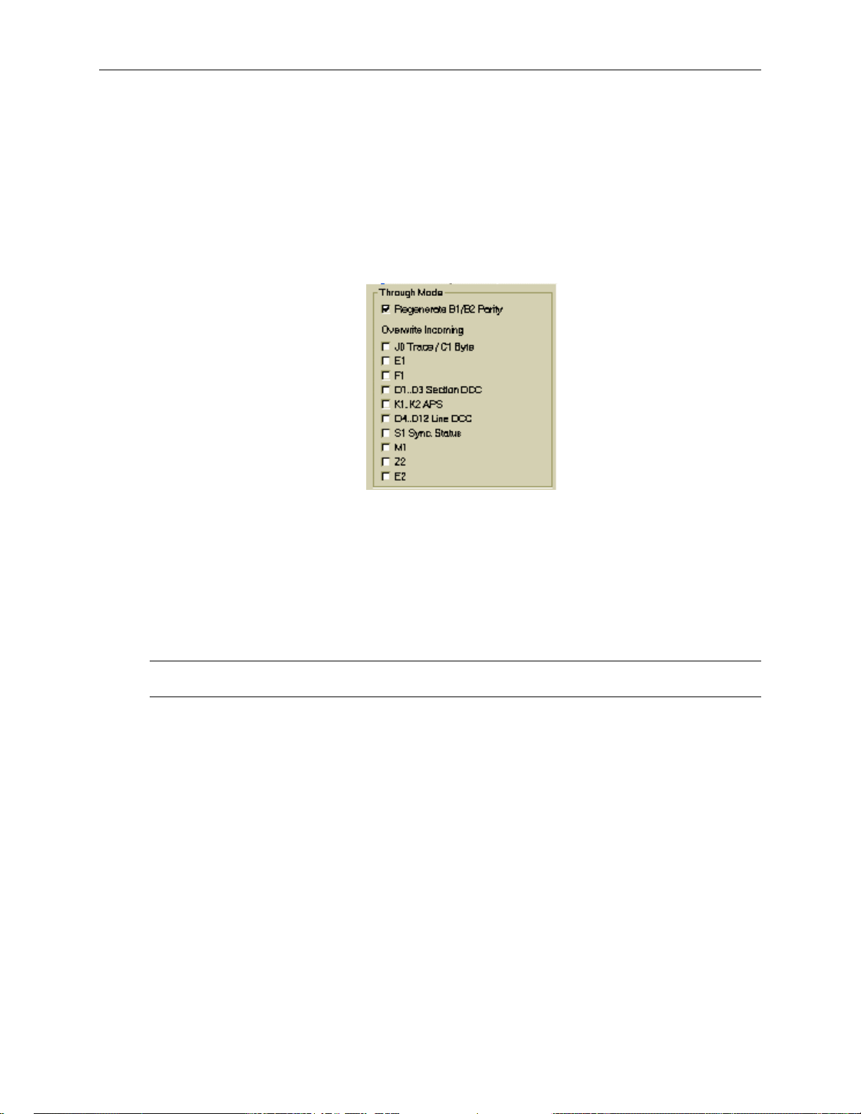
Operating Basics: User Interface
Through Mode
When using through mode, a number of the overhead bytes may be overwritten as the external
signal passes through the card. This is done through the use of the Through Mode selections
available in the Overhead menu, as shown in Figure 2-13. If the box is checked for Regenerate
B1/B2 Parity, the receiver will recalculate the B1/B2 parity and insert the new information into
the overhead as the signal is passed through the card. To disable B1/B2 parity regeneration,
ensure that the Regenerate B1/B2 Parity box is not selected.
Figure 2-13: Through Mode Overwrite menu
To overwrite an incoming byte, click in the box beside the selection under the Overwrite
Incoming heading. If you wish to keep a byte from being overwritten, make sure the box beside
the selection is not selected. The bytes available to be overwritten are J0 Trace/C1 Byte, E1, F1,
D1..D3 Section DCC, K1..K2 APS, D2..D12 Line DCC, S1 Sync Status, M1, Z2, and E2. Parity
regeneration is always enabled if the user chooses to overwrite any incoming Overhead bytes.
NOTE: There is no explicit byte edit for M1. Checking the M1 overwrite setting provides the ability
to insert REI-L.
2-32 OTS9100 User Manual
Page 62

Operating Basics: User Interface
J0 Multi-Byte Trace
J0 Trace provides a capability to uniquely identify each of the multiple channels being carried in
a Dense Wave Division Multiplexer (DWDM) system, providing an end-to-end continuity check.
Since only the SONET framing byte plus J0 are in the unscrambled overhead of the SONET
signal, it is possible to extract for display the J0 trace to confirm channel ID.
The OTS9100 has the ability to generate unique J0 traces. This allows test signals to be easily
identified, or to simulate network-element generated traffic without the Trace Identifier
Mismatch (TIM) alarm being generated. The OTS9100 capability to display the received J0 trace
allows users to verify continuity and correct routing of individual channels within the multichannel DWDM system.
Figure 2-14: Transmitter J0 Trace dialog box
To edit, click on the Edit J0 Trace button. A dialog box is displayed, as shown in Figure 2-14,
reflecting the current settings of the J0 Trace. Click the appropriate radio button to choose
between No Trace, 16 Byte Trace, and 64 Byte Trace. To input a Trace Value, click in the Trace
Value box and start typing. When edits are complete, click OK to return to the main menu. In
16-byte, the last byte is filled with CRC. In 64-byte, the last two bytes are filled with CR LF.
OTS9100 User Manual 2-33
Page 63

Operating Basics: User Interface
Transmitter – Path Overhead
The Path overhead property menu, as shown in Figure 2-16, of the Transmitter setup can be used
to pass or change the 9.95238 Gb/s signal path overhead bytes in the first STS-1 or STM-1 of the
OC-192 or STM-64 frame, respectively. In addition, the J1 Trace and C2 path label may be
edited. The editing procedure for each is described in more detail in the following sections.
NOTE: Overhead data displays are in hexadecimal format. All edits to overhead display must be
in hexadecimal format.
Figure 2-16: Transmitter – Path Overhead Property Menu
2-34 OTS9100 User Manual
Page 64

Operating Basics: User Interface
Edit Path Overhead
To edit the path overhead, click the Edit
button. This brings up a Path Overhead
dialog box, shown in Figure 2-17. The
dialog box displays the overhead bytes in
white text boxes. To edit, highlight the
appropriate box and type in the desired
entry. To set the overhead back to its
default state, click the Restore Defaults
button. When editing is complete, click OK
to return to the main screen.
Path Through Mode
When using through mode, a number of the
Path overhead bytes may be overwritten as
the external signal passes through the
module. This is done through the use of the
Through Mode selections available in the
Path Overhead menu, as shown in Figure 2-
18. If the box is checked for Regenerate B3
Parity, the receiver will recalculate the B3
parity and insert the new information into the
overhead as the signal is passed through the module.
To disable B3 parity regeneration, ensure that the
Regenerate B3 Parity box is not selected.
Figure 2-17:
Path Overhead
dialog box
To overwrite an incoming byte, click in the box beside
the selection under the Overwrite Incoming heading.
If you wish to keep a byte from being overwritten,
make sure the box beside the selection is not checked.
The bytes available to be overwritten are J1 Trace, C2,
G1, F2, H4, Z3, Z4, and Z5. B3 parity regeneration is
always enabled if any of the byte or payload overwrite
selections are checked.
If Overwrite Payload is checked, the payload data is
replaced with the Test Pattern selected on the Signal
page.
NOTE: There is no explicit byte edit for G1. Checking
the G1 overwrite setting provides the ability to insert
REI-P.
NOTE: The Tx Signal
Structure in the Tx
Setup menu must
match the Signal
Structure of the mating
Rx in order for intrinsic
Path Through mode to
operate correctly. If the
Signal Structure of the
Tx does not match the
Signal Structure of the
Rx, the overwritten
bytes will not be
accurate. This is also
true for B3
regeneration.
OTS9100 User Manual 2-35
Page 65

Operating Basics: User Interface
J1 Multi-Byte Trace
J1 Trace provides a capability to uniquely identify each of the multiple channels being carried in
a Dense Wave Division Multiplexer (DWDM) system, providing an end-to-end continuity check.
It is possible to extract for display the J1 trace to confirm channel ID.
The OTS9100 has the ability to generate unique J1 traces. This allows test signals to be easily
identified, or to simulate network-element generated traffic without the Trace Identifier
Mismatch (TIM) alarm being generated. The OTS9100 capability to display the received J1 trace
allows users to verify continuity and correct routing of individual channels within the multichannel DWDM system.
Figure 2-19: Transmitter J1 Trace dialog box
To edit, click on the Edit J1 Trace button. A dialog box is displayed, as shown in Figure 2-19,
reflecting the current settings of the J1 Trace. Click the appropriate radio button to choose
between No Trace, 16 Byte Trace, and 64 Byte Trace. To input a Trace Value, click in the Trace
Value box and start typing. When edits are complete, click OK to return to the main menu. In
16-byte, the last byte is filled with CRC. In 64-byte, the last two bytes are filled with CR LF.
2-36 OTS9100 User Manual
Page 66

Transmitter – Error Insertion
The error insertion menu, as shown in Figure 2-21, of the Transmitter setup allows the user to
inject anomalies and defects.
Operating Basics: User Interface
Figure 2-21: Transmitter Error Insertion menu
The menu is broken into two separate sections:
Anomaly Insertion – provides the ability to inject a single anomaly or continuously
inject at a selected rate.
Defect Insertion - provides the ability to inject a defect as a single burst or in
continuous insertion
OTS9100 User Manual 2-37
Page 67

Operating Basics: User Interface
Anomaly Insertion
Figure 2-22: Anomaly Insertion of the Error Insertion menu
The anomaly insertion section of the error insertion menu, as shown in Figure 2-22, provides all
controls for inserting anomalies. The Anomaly Insertion Setup, shown to the left of the example
(Figure 2-22), provide menus for anomaly insertion setup. The Current Anomaly Insertion and
Insertion Control, shown to the right, supply information on the current insertion state and
provide the insertion controls.
To select the type of anomaly injected, use the pull-down menu labeled Type under Anomaly
Insertion Setup. The anomaly types available are B1 BIP, B2 BIP, B3 BIP, MS REI (REI-L),
Payload Bit, Random Bit, REI-P, and Random Bit (SPE only). To choose an anomaly rate, click
on the arrows or highlight and type in the boxes labeled Rate. Or click on the Max Rate button
to inject the maximum rate.
NOTE: For these changes to take place, the Apply Anomaly Setup Changes button must be
clicked. The Current Anomaly Insertion settings will then reflect the new changes.
The ability to insert single B2 anomalies in either the first B2 only or the first B2 in each STMn/OC-n structure can also be selected by clicking the appropriate radio button.
To start the anomaly injection, click one of the buttons under Insertion Control.
• Insert Single – Clicking on this button will inject a single anomaly of the type reflected under
Current Anomaly Insertion.
• Start Continuous Insertion – Clicking on this button will inject a continuous insertion of the
anomaly type reflected under Current Anomaly Insertion at the indicated rate.
Anomaly Insertion and Through Mode
When inserting an anomaly in through mode, the user must check the appropriate overwrite box
for the anomaly type. For example, to insert a B1 or B2 error, the Regenerate B1/B2 Parity box
must be selected or the error will have no effect. The list of available anomaly types is
dependent upon the overwrite controls enabled. Thus, if no overwrite controls are selected, the
anomaly list will be quite short.
2-38 OTS9100 User Manual
Page 68

Defect Insertion
The Defect Insertion section of the Error Insertion menu, as shown in Figure 2-23, provides all
controls for inserting defects. The Defect Insertion Setup, on the left side, provides menus for
defect insertion setup. The Current Defect Insertion and Insertion Control, on the right side,
supply information on the current insertion state and provide the insertion controls.
To select the type of defect injected, use the pull-down menu labeled Type under Defect
Insertion Setup. The defect types available are LOS, LOF, MS AIS (AIS-L), MS RDI (RDI-L),
AIS-P, RDI-P, ERDI-P Payload, ERDI-P Server, ERDI-P Connectivity, and LOP-P. To choose a
defect burst time, click on the arrows or highlight and type in the boxes labeled Burst.
Operating Basics: User Interface
Figure 2-23: Defect Insertion of the Error Insertion menu
NOTE: For these changes to take place, the Apply Defect Setup Changes button must be clicked.
The Current Defect Insertion settings will then reflect the new changes.
To start the defect insertion, click one of the buttons under Insertion Control.
• Insert a Burst – Clicking on this button will inject a single burst of the defect type reflected
under Current Defect Insertion.
• Start Continuous Insertion – Clicking on this button will continuously inject the defect type
reflected under Current Defect Insertion.
OTS9100 User Manual 2-39
Page 69

Operating Basics: User Interface
Transmitter – K1, K2 Decode
The K1, K2 Decode menu, as shown in Figure 2-24, of the Transmitter setup allows the user to
edit the K1 and K2 bytes for Automatic Protection Switching (APS) measurements.
Figure 2-24: Transmitter – K1, K2 Decode menu
To edit, click the Edit K1,K2 Bytes button. This brings up a dialog box, shown in Figure 2-25.
The dialog box displays the current K1,K2 settings and allows the option to edit the byte via
hexadecimal or symbolic form (a subset of 0x00...0xFF).
2-40 OTS9100 User Manual
Page 70

Operating Basics: User Interface
Figure 2-25: Edit K1, K2 Bytes dialog box
For K1, type in the channel being set and click on the Request pull-down menu to select the new
value. The values available from the pull-down menu are:
• (0) No Request
• (1) Do Not Revert
• (2) Reverse Request
• (3) Unused
• (4) Exercise
• (5) Unused
• (6) Wait to Restore
• (7) Unused
• (8) Manual Switch
• (9) Unused
• (10) Signal Degrade, Low Priority
• (11) Signal Degrade, High Priority
• (12) Signal Fail, Low Priority
• (13) Signal Fail, High Priority
• (14) Forced Switch
• (15) Lockout of Position
For K2, type in the bridged channel being set then use the pull-down menus to select the
architecture and mode. The values available from the architecture pull-down menu are:
• (0) 1 + 1
• (1) 1 + N
OTS9100 User Manual 2-41
Page 71

Operating Basics: User Interface
The values available from the mode pull-down menu are:
• (0) Idle
• (1) Bridged
• (2) Bridged and Switched
• (3) Not Used (Span)/Ext TR (Ring)
• (4) Unidirectional
• (5) Bidirectional
• (6) RDI-L
• (7) AIS-L
2-42 OTS9100 User Manual
Page 72

Operating Basics: User Interface
Transmitter - IP Payload
The new Packet Over SONET (POS) feature characterizes physical layer performance of SONET
and SDH equipment by generating and measuring IP traffic.
Specifically, the POS feature provides the ability to determine physical layer operating limits
based on IP QoS. For instance, the sensitivity of IP routers to received laser power, optical jitter
tolerace, degraded Signal to noise, and frequency offset can be determined using IP
measurements.
The principle benefit of this additional feature is confidence that IP QoS is not preturbed by
conforming physical layer degradations. The POS feature is not intended to be a comprehensive
IP QoS tester but to enhance physical layer testing.
Figure 2-26: IP Header Menu
The IP Payload menu consists of property controls for Traffic, IP Header Setup, POS
Scrambling, IP Payload and Interframe Gap. To edit the IP Header click on the Edit IP Header
button. Drop down menus included in this menu allow the user to set specific properties.
IP Setup
The IP Payload data-gram starts with the IP header. The user can set the source and destination
IP addresses. The access to these fields is through the Edit IP Header button, as described in the
next section. The identification field of each data-gram contains a 16-bit number that is
incremented by one for each. The sequence does not restart but continues from one packet to the
next. The IP Setup area identifies the sequence and packet information.
POS Scrambling can be set to ON or OFF via the pull down menu.
The IP Payload is selectable by the pull down menu. The selections available are:
PRBS 31
16-bit Word, user-selectable
If the 16-bit Word is selected, an EDIT button and selection box is displayed.
OTS9100 User Manual 2-43
Page 73

Operating Basics: User Interface
The Interframe Gap is fixed at 16. Traffic can be stopped or started by clicking the button in the
Traffic section.
IP Header
To edit the IP Header click the button
to display the Edit IP Header dialog
box, as shown in Figure 2-27.
The grayed out areas of the dialog
box are fixed data not selectable by
the user. The user can modify the
information in the white boxes.
To modify the information, click in
the box and type in the new selection.
The IP Source Address contains a
four-byte (32-bit) with IPv4 Internet
address. This address identifies the
original source of the packets.
The IP Destination Address contains
a four-byte (32-bit) with IPv4 Internet
address. This address identifies the
final destination of the packets.
Figure 2-27: Edit Menu for IP Header
2-44 OTS9100 User manual
Page 74

Operating Basics: User Interface
Transmitter - IP Error Insertion
The IP Error Insertion Property menu consists of property controls for Stream Index, Error
Selection, Error Type, Error Rate, Minimum. Rate, Maximum. Rate, and Current Error Insertion
display drop down menus supply other options for each category.
Figure 2-28: IP Error Insertion Menu
The Stream Index is fixed at a value of 1.
The Current Error Insertion section is only available if there is an Error Type selected under the
Error Selection area.
Error Selection
The Error Type is selected by using the pull down menu. The Error Types available include:
• None
• HDLC FCS Error
• IP Payload Error
• IP Header Checksum Error
Once the error type is selected, the Error Rate must be selected. Use the up/down cursors or just
type in the rate. For the maximum rate, click the Max Rate button.
The default setting for error type is None so before the Current Error Insertion menu is available,
an error type must be selected and applied.
NOTE: The Apply Changes button must be clicked before the changes become active.
OTS9100 User Manual 2-45
Page 75

Operating Basics: User Interface
Current Error Insertion
The Current Error Insertion menu is only available when the error type applied is an actual error
type and not the default no error setting. The Current Error Insertion menu identifies the current
error type and error rate selected.
If the Insert Single button is clicked, a single error is inserted into the IP Payload. If the Start
Continuous Insertion button is clicked, errors are continuously inserted into the IP Payload. The
button changes to say Stop Insertion and ACTIVE is displayed in the Current Error Insertion
menu area.
To stop the error insertion, click the Stop Insertion button. The active notice is no longer
displayed and the button name returns to Start Continuous Insertion.
2-46 OTS9100 User Manual
Page 76

Receiver – Signal
The signal menu of the Receiver setup, as shown in Figure 2-26, allows the user to set the signal
standard and structure, the active channel, the test pattern, and the output pulse trigger. This
menu also indicates the current value of the receiver threshold offset. Drop down menus provide
other choices for test analysis. Each of the selections available is described in more detail in the
following sections.
Operating Basics: User Interface
Figure 2-26: Receiver Setup - Signal menu
Signal Standard
Signal Standard selects the operating mode of the receiver. To select either SONET or SDH
mode, click on the pull-down menu and select the desired operating mode. The operating mode
may also be selected via the menu bar. Click on System – Signal Standard and select either Set
to SONET or Set to SDH.
NOTE: If the signal standard is selected via the menu bar (View>Options), the signal standard is
set for all devices in the system.
OTS9100 User Manual 2-47
Page 77

Operating Basics: User Interface
BERT Mode
For some modules there is a third option available from the Signal Standard menu, the BERT
mode. With this mode, the OTS9100 becomes a BERT generator. The Test Pattern selection for
the active channel is the only valid selection on the transmitter signal setup page when BERT
mode is selected. When the signal standard is returned to either SONET or SDH mode, the
settings will return to the current selections in the setup menus.
Most LED indicators are also invalidated by the BERT mode. The only valid LEDs are Signal
Present, TSE, and LSS.
Signal Structure
Signal structure allows the user to choose the mapping structure of the received signal. The
mapping structures provided are listed in the table below. As shown, the structures all provide
concatenated structures.
1 x STS-192c 1 x VC4-64c
SONET SDH
4 x STS-48c 2 x VC4-16c
16 x STS-12c 16 x VC4-4c
64 x STS-3c 64 x VC4
192 x STS-1 192 x VC3
Active Channel(s)
The Active Channel(s) section controls the settings for signal structure and test pattern of the
selected active channel(s). To set the active channel, use the up/down cursors or click the Set
Channel button. When the Set Channel button is clicked, the bar for Active channel changes into
an interactive menu. Type in the text box to select the channel or click Set Channel 1 to choose
channel 1.
Test Pattern
Test Pattern allows the user the select a pattern to fill the chosen active channel of the internally
generated 9.95238 Gb/s signal. The patterns available are:
PN15 (PRBS 2^15-1), Inverted PN15 (ITU O.151)
PN23 (PRBS 2^23-1), Inverted PN23 (ITU O.151)
PN31 (PRBS 2^31-1), Inverted PN31 (ITU O.150)
All Zeros
All Ones
Fixed Data (8-bit)
In order to use the POS testing capabilities, POS must be selected as the Active Channel Test
Pattern. In addition, POS must be selected as the Active Channel Test Pattern in the Receiver
Setup menu.
NOTE: To receive a POS test pattern, the Signal Structure must be set to
STS-192c.
2-48 OTS9100 User Manual
Page 78
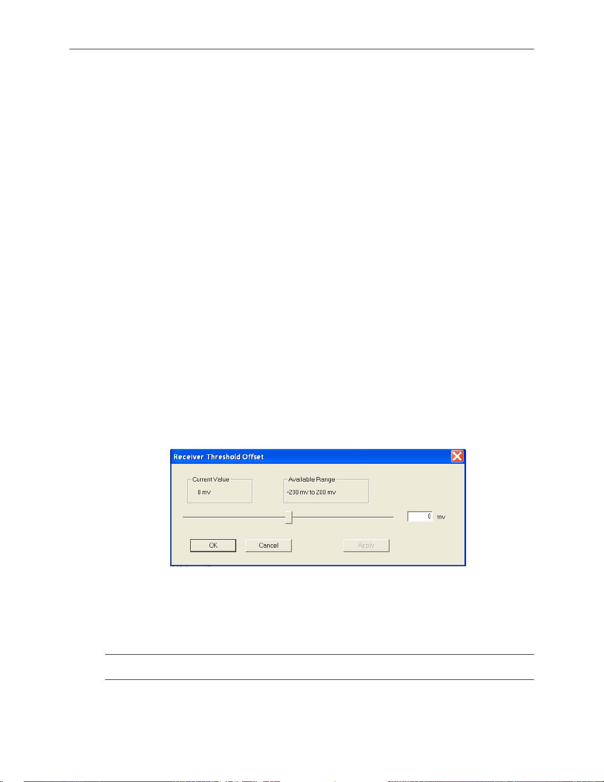
Operating Basics: User Interface
When Fixed Data is selected a button marked Edit Fixed Data is displayed. To change the Fixed
Data to a different value, click the Edit Fixed Data button and type the new value into the text
box beside the button. In the Test Pattern selection box, observe that the value after Fixed Data
changes to match the newly entered value.
SPE/VC3 Stuff Column Control
The stuff column control allows column 30 and column 59 of the SPE (VC3) to be stuffed with
either all zeros or with the payload pattern. This option is only available if the pattern is STS-1
or VC3.
Trigger Output
The Trigger Output allows the user to select what condition activates the output trigger. Check
the appropriate box for Anomaly, Defect, or Payload trigger, or activate all three. Triggering on
defects provides an active HIGH for each frame in which a defect is inserted. Triggering on
anomalies provides an active HIGH for each frame in which an anomaly is inserted. Triggering
on anomalies provides an active HIGH for every occurring TSE error.
Receiver Threshold Offset
The Receiver Threshold Offset provides a means to change the decision point of the signal eye.
The decision point is the point at which the signal is declared a one or a zero. The receiver
threshold offset allows the user to shift this decision point changing the offset. This ability is
useful during Q-factor analysis and accelerated BER testing.
To edit, click the Edit Rx Threshold Offset button, which then displays the Receiver threshold
offset dialog box as shown in Figure 2-27.
Figure 2-27: Receiver Threshold Offset dialog box
The current value of the receiver threshold offset is displayed in the upper left-hand corner under
the Current Value heading. The available range is shown in the right-hand corner. To change
the threshold offset, click and drag the slide bar then click Apply. The Current Value should
change to match the new value.
NOTE: The new value will not take affect until Apply is clicked. If the slide bar is changed but
Apply is not clicked, the Current Value will not change.
OTS9100 User Manual 2-49
Page 79

Operating Basics: User Interface
Receiver – Trace Mismatch
The trace mismatch menu of the Receiver setup, as shown in Figure 2-28, provides the setup
information for the J0/J1 Trace, C2 Status, and HP Detection. Each of the selections available is
described in more detail in the following sections.
Figure 2-28: Receiver Setup – Trace Mismatch menu
J0 Multi-Byte Trace
J0 Trace provides a capability to uniquely identify each of the multiple channels being carried in
a Dense Wave Division Multiplexer (DWDM) system, providing an end-to-end continuity check.
The OTS9100 has the ability to generate unique J0 traces. This allows test signals to be easily
identified, or to simulate network-element generated traffic without the Trace Identifier
Mismatch (TIM) alarm being generated. The OTS9100 capability to display the received J0 trace
allows users to verify continuity and correct routing of individual channels within the multichannel DWDM system.
To analyze, ensure the box beside the Analyze J0 Trace Mismatch is checked.
To edit, click on the Edit Expected J0 Trace button. A dialog box is displayed, as shown in
Figure 2-29, reflecting the current settings of the J0 Trace. Click the appropriate radio button to
choose between No Trace, 16 Byte Trace, and 64 Byte Trace. To input a Trace Value, click in
2-50 OTS9100 User Manual
Page 80

Operating Basics: User Interface
the Trace Value box and start typing. When the desired edits are complete, click OK to return to
the main menu. In 16-byte, the last byte is filled with CRC. In 64-byte, the last two bytes are
filled with CR LF.
Figure 2-29: J0 Trace Editor dialog box
J1 Multi-Byte Trace
J1 Trace provides a capability to uniquely identify each of the multiple channels being carried in
a Dense Wave Division Multiplexer (DWDM) system, providing an end-to-end continuity check.
To analyze, ensure the box beside the Analyze J1 Trace Mismatch is checked.
To edit, click on the Edit Expected J1 Trace button. A dialog box is displayed, as shown in
Figure 2-30, reflecting the current settings of the J1 Trace. Click the appropriate radio button to
choose between No Trace, 16 Byte Trace, and 64 Byte Trace. To input a Trace Value, click in
the Trace Value box and start typing. In 16-byte, the last byte is filled with CRC. In 64-byte, the
last two bytes are filled with CR LF.
Figure 2-30: J1 Trace Editor dialog box
Edit C2 Byte
OTS9100 User Manual 2-51
Page 81

Operating Basics: User Interface
The C2 byte is the Path Signal label. The C2 byte can be any value from 0x00 to 0xFF and may
be set in hexadecimal or symbolic form.
To edit, click the Edit Expected C2 button. This brings up a dialog box, shown in Figure 2-31.
The dialog box displays the current C2 setting and allows the option to edit the byte via
hexadecimal or symbolic form (a subset of 0x00...0xFF).
To change the setting, click the radio button for Symbolic or Hex (hexadecimal). Type in the
text box by the Hex heading to input a new value or click on the Symbolic button and click on
the pull-down menu. The values available from the pull-down menu are:
Figure 2-31: Edit C2 dialog box
• (00) Unequipped
• (01) Equipped – Nonspecific
• (02) VT-Structured STS-1 SPE
• (03) Locked VT Mode
• (04) Asynchronous Mapping for DS3
• (12) Asynchronous Mapping for DS4NA
• (13) Mapping for ATM
• (14) Mapping for DQDB
• (15) Asynchronous Mapping for FDDI
• (16) HDLC-Over-SONET Mapping
• (FE) O.181 Test Signal (TSS1 to TSS3) Mapping
• (FF) Reserved
2-52 OTS9100 User Manual
Page 82

Operating Basics: User Interface
HPPLM and HP Unequipped Detection
If Anaylysis Path Label Mismatch box is checked the Detect any Mismatch and Detect Signal
Label Mismatch per GR253 Table 6-2 boxes are enabled and Path Label Mismatch is analyzed,
otherwise the boxes are disabled and Label Mismatch will not be analyzed.
For the HP Unequipped Detection section, if the box is checked, the Unequipped High Path is
analyzed.
OTS9100 User Manual 2-53
Page 83

Operating Basics: User Interface
Receiver – IP Setup
The IP Setup menu of the Receiver setup, as shown in Figure 2-6, provides the IP setup
information. Each of the selections available is described in more detail in the following
sections.
Figure 2-6: Receiver Setup – IP Setup menu
The Stream Index is fixed at a value of 1.
IP Setup
The IP Payload data-gram starts with the IP header.
POS Scrambling can be set to ON or OFF via the pull down menu.
The IP Payload is selectable by the pull down menu. The selections available are:
PRBS 31
16-bit Word, user-selectable
If the 16-bit Word is selected, an EDIT button and selection box is displayed.
2-54 OTS9100 User Manual
Page 84

Operating Basics: User Interface
Setup - Summary
The Setup Summary menu, as shown in Figure 2-32, provides a summary of the setup conditions
for each Transmitter and Receiver individually. Clicking on the Turn Laser OFF buttons will
turn the laser off. Clicking on the Receiver Setup will display the Receiver Setup menu for the
specific Receiver number chosen. Clicking on the Transmitter Setup will display the last edited
menu tab of the Transmitter Setup menu for the specific Transmitter number chosen.
Figure 2-32: Setup Summary menu
OTS9100 User Manual 2-55
Page 85

Operating Basics: User Interface
Signal Monitor Menus
When Signal Monitor is selected from the Navigation window, icons for all loaded Receiver
modules are displayed. The Signal Monitor menu provides separate configuration control over
each receiver by these individual icons.
If an Rx icon is clicked, the Receiver signal monitor menu is displayed. This menu contains four
separate menu screens; each selected by a tab. These tabs, Transport Overhead, Path Overhead,
K1,K2 Decode, and Payload, each display an aspect of the Signal Monitor function.
Receiver – Transport Overhead
The transport overhead menu, as shown in Figure 2-33, displays the current activity of the
transport overhead as monitored by the selected receiver. The Section Trace (J0) and the S1
Synchronization Status provide additional information received.
Figure 2-33: Signal Monitor – Transport Overhead
The Transport Overhead section displays the overhead for the selected STM-1/STS-3. The
information presented on the screen is constantly updated. To suspend the update, click the
Pause Update button. The button will change to a Resume Update button and will say
“PAUSED” beside it, as shown in Figure 2-34. The display will not be updated again until the
Resume Update button is clicked.
NOTE: Pausing the update only suspends the local display updates, the OTS9100 is still
capturing data.
NOTE: The title at the top of the menu reflects the overhead in the mode of the selected receiver,
not the notation selected through the options menu.
2-56 OTS9100 User Manual
Page 86

RS Trace (Section Trace) (J0)
The Section Trace (J0) provides the current values of the J0 multi-byte trace. The 16-byte J0
Trace receives 15 bytes ending with a CRC. The 64-byte J0 Trace receives 62 bytes with CR LF.
The Expected and Received values are both displayed, providing an easy visual comparison of
the J0 Trace. The length of the Trace is also provided as both expected and received values.
S1 Synchronization Status
S1 Synchronization Status displays the S1 byte values. The S1 byte values are decoded and
displayed in ASCII format. To edit the S1 byte, go to the Overhead section of the Transmitter
setup and enter the desired hexadecimal value.
The S1 byte display is only active when the overhead channel is set to 1.
Operating Basics: User Interface
OTS9100 User Manual 2-57
Page 87

Operating Basics: User Interface
Receiver – Path Overhead
The path overhead menu, as shown in Figure 2-35, displays the current activity of the path
overhead as monitored by the selected receiver. The Path Trace (J1) and the C2 Status provide
additional information received.
Figure 2-35: Signal Monitor – Path Overhead
The Path Overhead section displays the overhead for the selected STM-1/STS-3. The
information presented on the screen is constantly updated. To suspend the update, click the
Pause Update button. The button will change to a Resume Update button and will say
“PAUSED” beside it. The display will not be updated again until the Resume Update button is
clicked.
NOTE: Pausing the update only suspends the local display updates, the OTS9100 is still
capturing data.
The listed channel refers to the active channel of the receiver. Only the active channel payload
can be monitored. To change this display, change the active channel in the receiver signal menu
setup.
2-58 OTS9100 User Manual
Page 88

Path Trace (J1)
The Path Trace (J1) provides the current values of the J1 multi-byte trace. The 16-byte J1 Trace
receives 15 bytes ending with a CRC. The 64-byte J1 Trace receives 62 bytes with CR LF. The
Expected and Received values are both displayed, providing an easy visual comparison of the J1
Trace. The length of the Trace is also provided as both expected and received values.
C2 Status
C2 Status displays the received and expected C2 byte values. The C2 byte value is decoded and
displayed in ASCII format. To edit the C2 byte, go to the Path Overhead section of the
Transmitter setup and enter the desired hexadecimal value.
Operating Basics: User Interface
OTS9100 User Manual 2-59
Page 89

Operating Basics: User Interface
Receiver – K1,K2 Decode
The K1,K2 Decode signal monitor screen, as shown in Figure 2-36, displays the received results
of the K1, K2 bytes.
Figure 2-36: Signal Monitor – K1,K2 Decode
2-60 OTS9100 User Manual
Page 90

Receiver – Payload
The Payload signal monitor screen, as shown in Figure 2-37, provides a graphical representation
of the signal structure of the system. The system analyzes the incoming signal and displays the
configuration. Any of the structures can be clicked and the identifying information for that
channel is displayed.
Operating Basics: User Interface
Figure 2-37: Signal Monitor – Payload
OTS9100 User Manual 2-61
Page 91

Operating Basics: User Interface
Test Control Menu
When Test Control is selected from the Navigation window, the Test Control menu is displayed,
as shown in Figure 2-38. The Test Control menu allows the user to choose the type of test to run
and the time the test will run.
Figure 2-38: Test Control Menu
The Current Test section describes the state of the current test and the time of the current test.
The Test Control section provides the current test mode and provides an edit box for the user to
include a description of the current test. To edit the test control settings, click on the Edit Test
Control Settings button. The Test Parameters dialog box, shown in Figure 2-39, is now
displayed.
2-62 OTS9100 User Manual
Page 92

Operating Basics: User Interface
The Test Mode section enables the user to set continuous, timed, or timed-repetitive tests. The
Continuous setting configures the test cycle so that it will run continuously from the time that the
Start button is clicked until the Stop button is clicked. The Timed setting configures the test
cycle to run the test for the duration of the test time. The Timed-Repetitive setting configures the
test cycle to run the test for the duration of the test time and then to repeat the same test again. To
choose the Test Mode click the appropriate radio button.
Figure 2-39: Test Control Parameters dialog box
The Test Duration section provides the means to set the length of the test if the Timed or TimedRepetitive tests were chosen. To set the test duration select the desired test length time by
clicking up/down arrows in the Days, Hours, Minutes, and Seconds boxes.
By clicking in the box labeled Test Description, a description of the test may be entered. When
editing is finished, click OK to return to the Test Control menu.
OTS9100 User Manual 2-63
Page 93

Operating Basics: User Interface
Test Control Summary
The Test Control Summary menu, as shown in Figure 2-40, provides a summary of the test
control conditions for each Receiver individually. Clicking the Edit button will display the Test
Control menu for the specific receiver number chosen. Clicking the Start button will begin a test
on the specific receiver number chosen. Once the Start button is clicked, it changes to a Stop
button. The Pause button is grayed out until a test is started, then it may be clicked to pause a
test.
Figure 2-40: Test Control Summary menu
2-64 OTS9100 User Manual
Page 94

Measurements Menu
When Measurements is selected from the Navigation window, the Measurements menu is
displayed. The Measurements menu provides separate configuration control over each receiver
through associated icons.
If an Rx icon is clicked, the Receiver signal monitor menu is displayed. This menu contains
separate menu screens; each selected by a tab. These tabs, each display an aspect of the Receiver
Measurement function.
Receiver - Real-Time
The Real-Time menu has four tab selections provided as property page display choices: RealTime, Cumulative, History and IP Measurements. The real-time display menu provides the
ability to view the errored seconds, error counts, and error ratios for each error condition
monitored during the last n seconds (up to sixty). There is a Section and Line View, a Path View
and a Selected View. If Selected is chosen, a window is displayed, which allow the user to select
four error measurements.
Operating Basics: User Interface
Figure 2-41: Real-Time menu – Section and Line display
OTS9100 User Manual 2-65
Page 95

Operating Basics: User Interface
Figure 2-42: Real-Time menu – Path display
Figure 2-42: Real-Time menu – Selected display
2-66 OTS9100 User Manual
Page 96

Receiver - Cumulative
The cumulative menu has two selections on the top for Display choices, Section and Line, and
Path. The cumulative display menu provides a summary of the errored seconds, error counts, and
error ratios for each error condition monitored during the test. The results are accumulated while
the test is in progress and are cleared when a new test begins. The measurements shown reflect
the display choice, as shown in Figures 2-44 and 2-45.
Operating Basics: User Interface
Figure 2-44: Cumulative Measurements Display – Section and Line
OTS9100 User Manual 2-67
Page 97

Operating Basics: User Interface
Figure 2-45: Cumulative Measurements Display - Path
2-68 OTS9100 User Manual
Page 98

Operating Basics: User Interface
Receiver – History
The history display shows the results history data collected by the associated receiver during the current
or most recent test, as shown in Figures 2-46 and 2-47. The selections for display choices are
Section/Line and Path.
Figure 2-46: Example of Results History Data – Section/Line
OTS9100 User Manual 2-69
Page 99

Operating Basics: User Interface
Figure 2-47: Example of Results History Data –Path
The upper window shows a trace for each measurement parameter. A dark rectangle is shown for a
measurement interval during which an errored second occurred (LOS, LOF, LOP, SEF/OOF, TIM, AIS,
RDI, PLM, UNEQ, LSS) or one or more errors were counted (B1, B2, B3, FAS, REI, BIT/TSE).
The lower window shows a bar-graph display (B1, B2, FAS, REI) of the anomaly selected by
the Detail View selector. The display may be linear or logarithmic, and is automatically scaled
based on the maximum value for that parameter.
The Zoom Out/In slider sets the display’s time axis. The limits are 1 second/tick to 1 hour/tick.
The display and the detail view scale are set accordingly.
The Scroll bar scrolls the display horizontally.
The display Time Axis may be set to show elapsed test time or time of day. Elapsed test time
does not accrue when a test is paused; time of day continues.
The Cursor, shown as a colored line on the display, identifies a particular measurement sample.
It may be positioned in several ways:
Incrementally, by moving it with the four Cursor buttons
Directly, by clicking the mouse in one of the data windows.
Directly, by entering a time value in the Cursor field and clicking the Set button.
When the Time Axis display is set to Elapsed Time, the cursor position may be entered:
In seconds, e.g., 135
In hours:minutes:seconds, e.g., 2:15 or 0:2:15
In days, hours, minutes, seconds, e.g., 3d 4h 2m 15s
2-70 OTS9100 User Manual
Page 100

Operating Basics: User Interface
If the first character of the time specification is a plus (+) or minus (–) sign, the time is taken
relative to the current cursor position.
When the Time Axis display is set to Time of Day, times are taken as time-of-day; day
specifications are relative to 0, the first day of the test. Thus, 1:00 PM on the day following the
start of the test would be entered as 1d 13:00:00.
The Live Update check box causes the data display to track new data as a test is running. When
it is set, the cursor is automatically positioned on the most recently acquired sample and the
windows scroll accordingly. Moving the cursor automatically turns off this feature.
When the Zoom Out/In slider is set to a resolution other than the finest, the display may be
automatically zoomed by clicking the mouse at one edge of the area of interest, holding down
the left button, and dragging it to the other edge. The zoom setting and scroll position will adjust
to show the selected area at the highest resolution possible.
The Test window shows the test start time and date, elapsed time, and test state.
The Data at Cursor window shows the cursor position (elapsed time or time-of-day, as
selected), the count of the selected parameter at the cursor, and the maximum value for that
parameter at the current display resolution.
The Search controls allow searching, forward or backward, for an occurrence of the specified
parameter. The search starts from the cursor location; it will not wrap beyond the end (forward)
or beginning (backward) of the data. For the B1, B2, FAS, MS-REI (REI-L), B3, REI-P, and
TSE parameters, one may specify a search threshold: the search will find only intervals
containing at least that many errors.
OTS9100 User Manual 2-71
 Loading...