

Page 1

pp
User Manual
gigaBERT1400
1400 Mb/s Bit Error Rate Tester
Generator and Analyzer
071-0590-00
This document supports firmware version 2.2 and above.
Page 2

Copyright © 2000 Tektronix, Inc. All rights reserved. Licensed software
products are owned by Tektronix or its suppliers and are protected by United
States copyright laws and international treaty provisions.
Use, duplication, or disclosure by the Government is subject to restrictions as set
forth in subparagraph (c)(1)(ii) of the Rights in Technical Data and Computer
Software clause at DFARS 252.227-7013, or subparagraphs (c)(1) and (2) of the
Commercial Computer Software - Restricted Rights clause at FAR 52.227-19, as
applicable.
Tektronix products are covered by U.S. and foreign patents, issued and pending.
Information in this publication supersedes that in all previously published
material. Specifications and price change privileges reserved.
Tektronix, Inc., P.O. Box 1000, Wilsonville, OR 97070-1000
TEKTRONIX and TEK are registered trademarks of Tektronix, Inc.
GB1400 User Manualii
Page 3

WARRANTY
Tektronix warrants that this product will be free from defects in materials and workmanship for a
period of one (1) year from the date of shipment. If any such product proves defective during this
warranty period, Tektronix, at its option, either will repair the defective product without charge
for parts and labor, or will provide a replacement in exchange for the defective product.
In order to obtain service under this warranty, Customer must notify Tektronix of the defect
before the expiration of the warranty period and make suitable arrangements for the performance
of service. Customer shall be responsible for packaging and shipping the defective product to the
service center designated by Tektronix, with shipping charges prepaid. Tektronix shall pay for
the return of the product to Customer if the shipment is to a location within the country in which
Tektronix service center is located. Customer shall be responsible for paying all shipping charges,
duties, taxes, and any other charges for products returned to any other locations.
This warranty shall not apply to any defect, failure or damage caused by improper use or
improper or inadequate maintenance and care. Tektronix shall not be obligated to furnish service
under warranty a) to repair damage resulting from attempts by personnel other than Tektronix
representatives to install, repair or service the product; b) to repair damage resulting from
improper user or connection to incompatible equipment; or c) to service a product that has been
modified or integrated with other products when the effect of such modification or integration
increases the time or difficulty of servicing the product.
THIS WARRANTY IS GIVEN BY TEKTRONIX WITH RESPECT TO THIS PRODUCT
IN LIEU OF ANY OTHER WARRANTIES, EXPRESSED OR IMPLIED. TEKTRONIX
AND ITS VENDORS DISCLAIM ANY IMPLIED WARRANTIES OF
MERCHANTABILITY OR FITNESS FOR A PARTICULAR PURPOSE. TEKTRONIX’
RESPONSIBILITY TO REPAIR OR REPLACE DEFECTIVE PRODUCTS IS THE
SOLE AND EXCLUSIVE REMEDY PROVIDED TO THE CUSTOMER FOR BREACH
OF THIS WARRANTY. TEKTRONIX AND ITS VENDORS WILL NOT BE LIABLE
FOR ANY INDIRECT, SPECIAL, INCIDENTAL, OR CONSEQUENTIAL DAMAGES
IRRESPECTIVE OF WHETHER TEKTRONIX OR THE VENDOR HAS ADVANCE
NOTICE OF THE POSSIBILITY OF SUCH DAMAGES.
GB1400 User Manual iii
Page 4

iv
How to Reach Customer Service
If you have any questions regarding the operation, maintenance, repair,
or application of your Tektronix equipment, contact your local sales
and service office. For a complete list of the Worldwide Sales and
Service Offices contact (800) 426-2200.
Tektronix provides high quality Technical Support on applications,
operation, measurement specifications, hardware, and software by
expert application engineers. For Applications Support, call the
Customer Support Center listed below.
Mailing
Address
Tektronix, Inc.
Measurement Business Division
P.O. Box 500
Beaverton, Oregon 97077-0001
USA
Customer
and Sales
Support
800-TEK-WIDE
or
800-835-9433 Ext 2400
Center
Direct
Fax
503-627-2400
503-627-5695
E-Mail tm_app_supp@tek.com
Web Site http://www.tek.com
Attn. Customer Service
Hours are 6:00 AM to 5:00 PM,
Pacific Time.
After hours Voice Mail is available.
GB1400 User Manual
Page 5

Table of Contents
Safety.................................................................................................. xii
Getting Started
Features............................................................................................... 1-1
Ordering Information ............................................................................ 1-4
gigaBERT comparison chart.................................................................. 1-5
Initial Self-Check Procedure ................................................................. 1-7
Operating Basics
Functional Overview....................................................................................... 2-1
BERT Basics - GB1400 ........................................................................ 2-2
Controls, Indicators, and Connectors...................................................... 2-4
Display Formats ................................................................................... 2-6
Outputs & Inputs.................................................................................. 2-9
Generator OUTPUT ....................................................................... 2-9
Generator CLOCK ......................................................................... 2-10
Generator OUTPUT (Set-up) ........................................................... 2-11
Generator Rear Panel...................................................................... 2-12
Changing the Line Fuse .................................................................. 2-12
Analyzer INPUT............................................................................ 2-13
Analyzer MONITOR ...................................................................... 2-14
Analyzer Rear Panel....................................................................... 2-15
Changing the Line Fuse .................................................................. 2-15
Connectors, Terminations and Levels .............................................. 2-16
Controls & Indicators............................................................................ 2-18
Power Switches .............................................................................. 2-18
Unit Mounting ............................................................................... 2-18
Unit Cooling .................................................................................. 2-18
View Angle and Panel Lock Keys ................................................... 2-18
Reset to Factory Default.................................................................. 2-18
GPIB Controls................................................................................ 2-19
Pattern Controls and Function Keys ................................................. 2-20
Function (Soft) Keys (F1, F2, F3, F4) ............................................... 2-21
GB1400 User Manual v
Page 6

Table of Contents
Generator ERROR INJECT ............................................................ 2-22
Analyzer INPUT............................................................................ 2-23
Analyzer Error History.................................................................... 2-24
Analyzer ERROR DETECTION ..................................................... 2-25
Analyzer SYNC Controls ................................................................ 2-25
Burst Mode Option ............................................................................... 2-26
Burst Mode Usage.......................................................................... 2-27
Specifications for Burst Mode ......................................................... 2-27
PECL Option for GB1400 Tx ................................................................ 2-29
Tutorial........................................................................................................... 2-30
Applications .................................................................................................... 2-38
Method for Very Fast Automatic RX Synchronization
and Eye Width Measurement ......................................................... 2-38
GB700/ GB1400 Optical Component Test........................................ 2-46
Reference
Menu Overview.................................................................................... 3-1
Functions common to TX and RX.......................................................... 3-1
Selecting a Pattern................................................................................ 3-2
Fibre Channel Link Testing Parallel and High-Speed Serial............... 2-47
Testing QPSK Modems, I & Q ........................................................ 2-48
QPSK BER Testing using PRBS Data for 2-Channel I & Q ............... 2-49
AC Power...................................................................................... 3-1
Selecting 115 VAC or 230 VAC operation ....................................... 3-1
Turning Instrument Power ON/OFF................................................. 3-1
LCD Viewing Angle ....................................................................... 3-1
Recalling Default Setup................................................................... 3-2
Locking the Front Panel.................................................................. 3-2
Pattern Definitions.......................................................................... 3-2
PRBS Patterns ............................................................................... 3-2
Word Patterns ................................................................................ 3-3
Selecting an Active Pattern................................................................... 3-3
Selecting PRBS Patterns ................................................................. 3-3
Selecting the Current Word Pattern.................................................. 3-3
Selecting (Recalling) a Saved Word Pattern..................................... 3-4
GB1400 User Manualvi
Page 7

Table of Contents
Word Patterns ...................................................................................... 3-5
Basics............................................................................................ 3-5
Creating Word Patterns using front panel controls ............................. 3-5
Creating Word Patterns using menus................................................ 3-7
Creating Word Patterns using remote control.................................... 3-8
Saving Word Patterns ..................................................................... 3-9
Recalling Word Patterns ................................................................. 3-9
Generator Functions ....................................................................................... 3-10
Clock Source and Frequency................................................................. 3-10
External Clock Input............................................................................. 3-10
Clock Source........................................................................................ 3-10
Step Size and Frequency ....................................................................... 3-10
Saving a Frequency.............................................................................. 3-11
Recalling a Frequency........................................................................... 3-11
Data and Clock Outputs ........................................................................ 3-12
Amplitude and Baseline Offset.............................................................. 3-14
Logically Inverting Output Data (D-INV) .............................................. 3-15
Single-Ended or Differential Operation ................................................. 3-16
Pattern SYNC (PYNC) and CLOCK/4 Outputs ...................................... 3-16
Error Injection ...................................................................................... 3-17
Selection an Error Inject Mode .............................................................. 3-17
Error INJECT Input.............................................................................. 3-18
Analyzer Functions ......................................................................................... 3-19
Automatic Setup Functions (SYNC)...................................................... 3-19
AUTO SEARCH with PRBS Patterns.................................................... 3-20
AUTO SEARCH with "Non-PRBS" Patterns ......................................... 3-21
How to DISABLE Automatic Pattern Resynchonization.......................... 3-21
Relationship between AUTO SEARCH and DISABLE........................... 3-21
Synchronization (LOCK) Threshold ....................................................... 3-22
Clock, Data, and Reference Data Inputs................................................. 3-23
Input Data Delay.................................................................................. 3-24
Input Termination................................................................................. 3-25
Input Decision Threshold ...................................................................... 3-26
Logically Inverting Input Data ............................................................... 3-26
GB1400 User Manual vii
Page 8

Table of Contents
Single-Ended or Differential Operation .................................................. 3-27
Selecting the Reference Data Mode ....................................................... 3-27
Monitor Outputs................................................................................... 3-28
Error Detection Set-up .......................................................................... 3-29
Display Mode: Totalize, Window or Test ............................................... 3-33
Clearing Results and Starting Tests ........................................................ 3-33
Totalize Process Setup.......................................................................... 3-33
Window Process Setup.......................................................................... 3-34
Test Process Setup................................................................................ 3-35
Viewing Results ................................................................................... 3-36
Printing Results (Reports) ..................................................................... 3-37
Result Definitions ................................................................................. 3-42
Error History Indicators ........................................................................ 3-44
CLEAR Control.................................................................................... 3-45
Audio (Beeper) Function....................................................................... 3-45
Analyzer Error Messages...................................................................... 3-45
Starting & Stopping Measurements........................................................ 3-46
Menus ............................................................................................................. 3-48
Functions Performed using the Menu System......................................... 3-48
Menu and Function "Pages".................................................................. 3-48
General Rules for using the Menu System .............................................. 3-51
Menu Summaries.................................................................................. 3-52
Menu Function Definitions.................................................................... 3-55
Word Edit (EDIT) .......................................................................... 3-56
Word Length (LENGTH) ................................................................ 3-57
Word Fill (FILL) ............................................................................ 3-58
Word Order (ORDER).................................................................... 3-59
Word Synchronization Threshold (SYNC) ....................................... 3-60
Buffer............................................................................................ 3-61
Auto .............................................................................................. 3-62
Test Length (LENGTH) .................................................................. 3-63
Test Mode (MODE) ....................................................................... 3-64
Test Reports (REPORT) ................................................................. 3-65
Test Threshold (THRES)................................................................. 3-66
Test Squelch (SQUEL)................................................................... 3-67
GB1400 User Manualviii
Page 9

Table of Contents
Test Print (PRINT)......................................................................... 3-68
Test View Previous (VIEW-PRE).................................................... 3-69
Test View Current (VIEW-CUR) .................................................... 3-70
Window Mode (MODE)................................................................. 3-71
Window Interval in Bits (BITS)....................................................... 3-72
Window Interval in Hrs:Min:Sec (SECOND)................................... 3-73
Window Reports (REPORT) ........................................................... 3-74
RS-232 Baud Rate (BAUD)............................................................ 3-75
RS-232 Parity (PARITY) ................................................................ 3-76
RS-232 Data Bits (SIZE) ................................................................ 3-77
RS-232 End-of-Line Char.(EOL)..................................................... 3-78
RS-232 Xon/Xoff (XON/XOFF)...................................................... 3-79
RS-232 Echo (ECHO) .................................................................... 3-80
GPIB............................................................................................. 3-81
Utility Option (OPTION) ................................................................ 3-82
Utility Version (VER) ..................................................................... 3-83
Time Option (DATE)...................................................................... 3-84
Time Option (TIME)....................................................................... 3-85
Appendices
Specifications .................................................................................................. A-1
BERT Primer/ Technical Articles ................................................................... B-1
Remote Commands ......................................................................................... C-1
Using GPIB, RS-232 ....................................................................................... D-1
Customer Acceptance Test ............................................................................. E-1
Default Settings .............................................................................................. F-1
Cleaning Instructions ..................................................................................... G-1
Pattern Editing Software ................................................................................ H-1
Theory of Operation ....................................................................................... I-1
Glossary.......................................................................................................... Glossary-1
Index .............................................................................................................. Index-1
GB1400 User Manual ix
Page 10

Table of Contents
List of Figures
2-1 Example of BERT Application........................................................ 2-2
2-2 Nominal Generator NRZ Data and Clock Output Waveforms ........... 2-3
2-3 & 2- 4 Generator (TX) Front & Rear Panels ..................................... 2-4
2-5 & 2-6 Analyzer (RX) Front & Rear Panels ....................................... 2-5
2-7 Generator Display .......................................................................... 2-6
2-8 Analyzer Display........................................................................... 2-7
2-9 Transmitter Burst Mode Operation.................................................. 2-28
2-10 Receiver Burst Mode Operation .................................................... 2-28
3-1 Nominal Generator Clock, Data Waveforms showing Amplitude,
Baseline Offset and Vtop................................................................ 3-13
3-2 Generator Clock and Data Output Equivalent Circuits...................... 3-17
3-3 Analyzer Clock and Data Input Equivalent Circuits .......................... 3-22
3-4 TOTALIZE Measurement Process.................................................. 3-30
3-5 WINDOW Measurements Process.................................................. 3-31
3-6 TEST Measurement Process........................................................... 3-32
B-1 Three-stage PRBS generator .......................................................... B-5
B-2 Four-stage PRBS generator............................................................ B-5
B-3 Seven-stage PRBS generator.......................................................... B-6
I-1 Block Diagram - GB1400 TX.......................................................... I-5
I-2 Block Diagram - GB1400 RX.......................................................... I-6
GB1400 User Manualx
Page 11

List of Tables
2-1 Generator Inputs & Outputs............................................................ 2-16
2-2 Analyzer Inputs & Outputs............................................................. 2-17
3-1 PRBS (2N-1) Test Patterns............................................................. 3-3
3-2 Output Setup Rules vs. Termination Impedance ............................... 3-14
3-3 Data Inhibit Logic .......................................................................... 3-18
3-4 Actions taken by Analyzer when Synchronization is Lost................. 3-20
3-5 Synchronization Threshold ............................................................. 3-22
3-6 How F2, F3 determine Input Set-up ................................................ 3-24
3-7 Input Terminations for CLOCK, DATA, and REF DATA ................ 3-25
3-8 Input Threshold Range as a Function of Termination ........................ 3-26
3-9 How to Tell which Display Mode is Active ...................................... 3-37
3-10 Menu Descriptions ....................................................................... 3-52
Table of Contents
3-11 Analyzer Menu System Overview ................................................. 3-53
3-12 Generator Menu System Overview................................................ 3-54
B-1 PRBS Polynomials and Shift Register feedback taps for PB200........ B-4
B-2 PRBS Polynomials, Shift Register feedback taps, GB700/ GB1400 .. B-4
GB1400 User Manual xi
Page 12
Safety
Safety Terms Used in This User's Guide
CAUTION!
WARNING! Indicates an operation or practice that could result in
Indicates an operation or practice that could harm the
instrument.
personal injury or loss of life.
Safety Labels Found on the Instrument
DANGER
High Voltage
Protective Ground
(Earth) Terminal
ATTENTION
Refer to Manual
AC Power
The instrument is designed to operate from a power source that provides no more
than 250 volts RMS between the two supply conductors or between either supply
conductor and ground.
Ground the Instrument
The GB1400 is grounded through its AC power cord. Plug this power cord only
into a properly grounded, three-conductor outlet. If you operate the instrument
without a proper ground then all metal surfaces on the instrument become
potential shock hazards.
To avoid potential hazards, use this product only as specified.
Use the Proper Fuse
Operating the instrument with an improper fuse creates a fire hazard. The correct
fuses to install in the GB1400 are shown below:
Power Voltage Fuse Type
115 VAC 5A, Slo-Blo
230 VAC 5A, Slo-Blo
Do Not Operate in Explosive Atmospheres
This instrument does not provide protection from static discharges or arcing
components and therefore must not be operated in an explosive atmosphere.
xii GB1400 User Manual
Page 13

Table of Contents
Do Not Remove Instrument Covers
To avoid a shock hazard and to maintain proper air flow, never operate the
GB1400 with any of its outside covers removed.
Static Sensitive Device Notice
GB1400 outputs use a GaAs FET design and therefore are susceptible to damage
from externally applied over-voltage or electrostatic discharge. Never apply
reverse voltage to DATA or CLOCK outputs or voltages that are outside the
range specified in Appendix A of this manual. Operate the instrument only in a
static-controlled environment.
SMA Connectors
Be careful when attaching test cables to SMA connectors. Always tighten the nut
on the SMA connector rather than the cable itself. Never tighten an SMA
connector nut using more than 10 lb.-in. of torque.
Behavior of Outputs - Turning Power On or Off
When the GB1400 Generator is powered or de-powered its DATA and CLOCK
outputs may saturate to their specified positive or negative rail, that is +2 V or - 2
V, for up to 400 milliseconds. If this condition could be harmful to your
equipment, then remove all connections to your GB1400 Generator CLOCK and
DATA outputs before powering or de-powering the instrument.
Unit Mounting
The GB1400 is designed to be placed: (1) flat on a level surface, capable of
supporting its weight, or (2) angled from the surface with the rotating carrying
handle. To change the handle's orientation, press both handle-locking buttons
(located at the hubs of the handle), rotate the handle to the desired angle, and
release the buttons. The handle will click into a locked position. Assure that the
handle is locked before placing the unit on a work surface. A Rack mounting
option is available for installation of the unit into a 19" rackmount. The rack
height for the GB1400 is 7 inches (four RMU).
Unit Cooling
The rear panel fan openings and top-mounted ventilation slots must be kept clear
for proper cooling of the unit. Allow a minimum of two (2) inches of rear panel
clearance, and one (1) inch of top clearance, while operating the unit.
GB1400 User Manual xiii
Page 14

Preface
This manual describes how to use the Tektronix GB1400 Test Set. The product is
also known by the name, gigaBERT1400. This manual is your primary source of
information on how to use the GB1400 functions.
How This Manual is Organized
This manual is divided into four sections: Getting Started, Operating Basics,
Reference, and Appendices.
Getting Started provides an overview of the GB1400 and describes first time
operation.
Operating Basics describes the hardware controls, indicators, connectors, and
display elements for Tx, Rx and the cabling required. There is also a tutorial and
an application note in this section.
Reference describes the LCD Menus and Screens.
The Appendices provide a listing of specifications, a BERT technology primer,
Theory of Operation, Remote Commands, default factory settings, an extensive
Customer Acceptance Test and other useful information.
Conventions
This manual uses the following conventions:
• The names of front-panel controls and menus appear in all upper case letters,
for example, TRANSMIT and HELP.
• Names appear in the same case in this manual as they appear on the display
screens of the GB1400.
• Within a procedure, a specific button to be pressed or a parameter to be
selected appears in boldface print.
Some procedures require several iterations of highlighting parameters and
selecting choices. Some procedures may require more than one menu button or
menu page selection as well.
xiv GB1400 User Manual
Page 15

Related Manuals
The following document is also complementary to the GB1400:
• The GB700 BER Tester User Manual (Tektronix part number
Preface
070-9393-02) describes how to operate the GB700 test set.
GB1400 User Manual xv
Page 16

Preface
GB1400 User Manualxvi
Page 17

Getting Started
Page 18

Getting Started
GB1400 Pattern Generator and Error Detector
Features
• Test digital data transmission up to 1400 Mb/s
• Set Data Rate with 1 kHz resolution
• Vary Clock and Data timing with 5 pS
resolution
• Phase-Synchronous Clock and Data Edge
Tracking
• 1-Mbit data pattern memory
• Measure Eye-Width at Specific BER
Automatically
• Auto-Synchronization Rx/Tx Lock-up
• Front panel or computer control operation
The GB1400 is a general-purpose 1400 Mb/s bit error rate tester (BERT) built to
meet the exacting standards of design engineers who need to verify and
characterize high-speed serial data transmission circuits, interfaces and systems.
While primarily a lab instrument, the GB1400’s compact design, full computer
programmability and relatively light weight also enable it to serve in
manufacturing ATE and field test applications.
The quality of a digital link depends on many factors, but everything comes
down to the issue of whether the circuit exhibits a satisfactory BER (bit error
rate) and has sufficient margin to function under stress conditions.
The GB1400 has all of the features you expect in a general-purpose BERT, and
some you expect only in more expensive instruments, such as automated eyewidth measurements at a specified BER, and the ability to accept an external
real-time data stream for bit error testing. Also, the GB1400 has options to add
advanced features, such as Burst Mode (which also extends external clock range
down to 150 kb/s), and a 1-Mbit programmable pattern memory option.
GB1400 User Manual 1-1
Page 19

Getting Started
Symmetrical, Low-Jitter Output Waveforms
The GB1400 generates low-jitter, symmetrical waveforms over its entire
operating frequency range. The clock and data ports provide both true and
inverted output signals. The instrument can drive single-ended or differential
ECL inputs.
Applications
The GB1400 is focused on the research, design, and manufacturing of
telecommunication components, modules, or links operating at data rates to
1400 Mb/s. It is frequently employed in testing and development well under this
top speed rating, where sharp clock and data waveforms are especially desired, or
where additional frequency range is thought to be needed in the future.
Sample Applications
• Development of Gigabit LAN/Data Comm Devices:
• High-Speed Fibre Channel, Ethernet
• Digital Video (MPEG, SDV, HDDV)
• Wideband Satellite Data Links
• SONET/SDH Network Devices up to OC-12e/STM4e
• High-speed GaAs/ECL/E/O device testing
• Test Clock Recovery Circuits
• Parallel-to-Serial Analysis with Tektronix MB100
• Testing of High Speed Fibre Channel links up to 1,063 Mb/s
• Gigabit Ethernet at 1,250 Mb/s.
• Testing of high-speed Optical Busses (Opto Bus, Opto Bahn) at 800 Mb/s per
channel.
• Satellite system testing and TDMA (Burst Mode) at 400, 800 Mb/s
• GaAs, ECL and optical component testing
PRBS Or User-Defined Test Patterns
The GB1400 can generate pseudo-random bit sequences (PRBS) up to 223−1 bits
and others up to 1-Mbit in length, via user-programmable patterns. Patterns can
be created locally using setup menus or externally by using a workstation or PC.
A PC Windows-based MLPE Pattern Editor software package comes with the
1-Mbit Memory Option. Externally created patterns can be downloaded via the
GPIB or RS-232 port. All user patterns are saved in battery-backed RAM.
1-2 GB1400 User Manual
Page 20

Getting Started
Adjustable Inputs For Maximum Flexibility
The clock and data ports on the GB1400 Error Detector accept both true and
inverted inputs. Single-ended or differential signals can be internally terminated.
Input data delay is adjustable over a 4 ns range to accommodate different clock
and data signal path delays.
Auto Search For Easy Setup
Auto search greatly simplifies the Error Detector setup. The GB1400 Error
Detector automatically synchronizes to the incoming signal by 1) Setting the
input data decision voltage to its optimum value; 2) Adjusting input data delay
for an optimum clock/data phase relationship; 3) Selecting the correct PRBS test
pattern; and 4) selecting the correct pattern polarity (normal or inverted).
It synchronizes with any pattern sourced by a gigaBERT Pattern Generator. It
can perform a bit-by-bit comparison of an external data stream via the Reference
Data input. Thus the GB1400 can perform bit error analysis on any data pattern
with a known good reference pattern.
Powerful Analysis And Reporting Functions
The GB1400 performs a full-rate, bit-by-bit analysis of the received signal. Bit
error results are then used to calculate three bit error rate (BER) measures. Total
BER is calculated from the last power-on or reset. Window BER is calculated
over a sliding window specified in terms of time (1 second to 24 hours) or bits
(18- to 116-bits). Test BER is calculated from the start of the current test. A hard
copy of all test results can be generated locally by connecting a printer to the
parallel printer port or GPIB or RS-232 port. Reports may be printed when an
error is detected, at the end of test intervals, or both.
Front Panel Or Automated Operation
The GB1400 provides easy operation augmented by set-up store and recall.
Clear, concise LCD displays of setup and results make it easy to use. The 1
Megabit memory option for both the Pattern Generator and the Error Detector is
sufficient for storing and outputting complex data such as SONET frames, ATM
cells, MPEG digital video, etc, allowing designers to simulate “live” traffic. The
GB1400 Pattern Generator and Error Detector can be controlled via the GPIB or
RS-232 interface ports. The gigaBERT remote command set includes commands
for all setup menus and front panel selections. The status of front panel indicators
and test results can be remotely accessed.
Burst Mode
BURST mode, allows for operation with non-continuous external clocks. Use of
BURST mode requires ECL-level signals with a minimum rate during the burst
of 150 kHz. This is an option to the GB1400. See a write-up on Burst Mode at
the end of the Functional Overview section of Chapter 2.
GB1400 User Manual 1-3
Page 21

Getting Started
Ordering Information
gigaBERT GB1400
1400 Mb/s BERT Generator and Detector. Not available in Europe.
Includes: Power Cord, Manual.
Opt. 02 - 75 Ohm Both Sets.
Opt. 05 - BURST Mode Both Sets.
Opt. 07 - Positive ECL (Pattern Generator Only).
Opt. 08 - 1-Mbit RAM WORD Both Sets & PC Pattern Editor Software.
Opt. 2M - Rack Mounts - 2 rackmount kits
Opt. A3 - Australian 240 V, 50 Hz.
gB1400T
1400 Mb/s BERT Pattern Generator.
Opt. 02 - 75 Ohm Pattern Generator Only.
Opt. 05 - BURST Mode Pattern Generator Only.
Opt. 07 - Positive ECL Pattern Generator Only
Opt. 08 - 1-Mbit RAM WORD, Generator Only, w/ PC Pattern Edit software
Opt. 1M - Rack Mount.
Opt. A3 - Australian 240 V, 50 Hz.
gB1400R
1400 Mb/s BERT Error Detector.
Opt. 02 - 75 Ohm Error Detector Only.
Opt. 05 - BURST Mode Error Detector Only.
Opt. 08 - 1-Mbit RAM WORD, Detector Only w/ PC Pattern Edit Software
Opt. 1M - Rack Mount.
Opt. A3 - Australian 240 V, 50 Hz
1-4 GB1400 User Manual
Page 22

Getting Started
GB Comparison
Feature
Transmitter
Frequency range
Internal Clock Source
External Clock
External Clock w/Burst Mode
Freq Resolution CR/LF
(Internal Clock)
Clock /Data
Output Amplitude
Clock/Data
Output Offset
Clock/Data Threshold
Resolution
Std. Programmable Memory 16 bits 128 Kbits 16 bits
Optional Memory 128 Kbits none 1 Mbit
PRBS Patterns (2n-1) 7,15,17,20,23 7,15,17,20,23 7,15,17,20,23
Burst Mode New Line
(External Clk Only)
Receiver
Frequency range
w/Burst Mode
Burst Mode (Ext Clk Only) Standard Feature Standard Feature Optional Feature
Clock/Data Input levels (max) 500 mV to 6.0 V p-p 500 mV to 6.0 V p-p 500 mV to 2.0 V p-p
Clock Input Threshold -3.00 to +4.5 V -3.00 to +4.5 V Fixed threshold levels
Data Input Threshold -3.00 to +4.5 V -3.00 to +4.5 V -1.5V to 1.0 V
Clock/Data Threshold
Resolution
Clock/Data Input Terminations GND, AC, -2V, +3V GND, AC, -2V, +3V GND, AC, -2V
Single-Ended operation Automatic selection Automatic selection Requires external
Clk/Data Delay Range /
Resolution
1
GB660/CSA907A
Tx and Rx
150 kHz to 700 MHz
150 kHz to 700 MHz
1
150 kHz to 700 MHz
1 kHz 1 kHz 1 kHz (was 10 kHz)
500mV to 2.0 V 500mV to 2.0 V 500mV to 2.0 V
-2.0V to +1.8 V -2.0V to +1.8 V -2.0V to +1.0 V
50 mV steps 50 mV steps 50 mV steps
Standard Feature Standard Feature Optional Feature
150 kHz to 705 MHz
150 kHz to 705 MHz
50 mV steps 50 mV steps 50 mV steps
±4 ns in 100 pS
steps
GB700
Tx and Rx
150 kHz to 705 MHz
150 kHz to 705 MHz
150 kHz to 705 MHz
150 kHz to 705 MHz
150 kHz to 705 MHz
±4 ns in 20 pS steps ±4 ns in 5 pS steps
GB1400
Tx and Rx
1 MHz to 1405 MHz
1 MHz to 1405 MHz
150 kHz to 1405 MHz
-2.0V to +1.8 V with
PECL opt.
1 MHz to 1405 MHz
150 kHz to 1405 MHz
2
cable
Note 1 Burst mode operation requires ECL levels and is DC coupled
Note 2 Single-ended operation requires ext. cable connection from rear panel DATA THRESHOLD SMA
GB1400 User Manual 1-5
Page 23

Getting Started
GB1400 Instrument Configurations - Standard and Burst Option
GB1400 instruments are sold with and without the BURST option. To determine if the burst option is
installed in a GB1400, press the F1 key several times until you get to the UTIL menu. Then select the
OPTION menu. The OPTIONS menu will tell you if the Burst option is installed in the unit. External
indications of the BURST option are unique labels for both transmitter and receiver. See a write-up on
Burst Mode at the end of the Functional Overview section of Chapter 2.
GB1400 with no Burst Option Standard instrument configuration
All standard configuration GB1400 Generators (no burst option) have an AC coupled external clock
input. All standard configuration GB1400 Analyzers (no burst option) have AC coupled paths in the
receiver clock input circuitry.
GB1400 with Burst Option
When the BURST option is installed in the GB1400, the AC coupled paths in both transmitter and
receiver are eliminated. This will also change several specifications listed in the table below. External
clock inputs to the GB1400 transmitter must be ECL levels when the BURST option is installed. Clock
inputs into the GB1400 receiver must be ECL levels and are terminated into 50 Ohms to -2V.
GB1400 Clock Signals for Standard and Burst and Instruments
Standard Coupling Burst (Option) Coupling
GB1400 TX
External Clock Input 50 Ohm, AC coupled,
2V max
GB1400 RX
Clock Input 50 Ohm, AC coupled,
2.0V max
50 Ohm to -2V, DC coupled,
ECL levels
50 Ohm to -2V, DC coupled,
ECL levels
1-6 GB1400 User Manual
Page 24

Initial Self-Check Procedure
You may perform the following procedure as an initial self-check of your
GB1400 Generator and Analyzer. It is also a useful introduction to the basic
features and operation of the GB1400.
The fan openings of the GB1400 needs 2-inches of clearance for proper
ventilation.
Procedure
1. Make sure both the Generator and Analyzer are equipped with the proper
fuse.
2. Make sure that the Generator and Analyzer rear-panel power switches
are ON, and that their front-panel power switches are in the STBY
position.
3. Plug both instruments into grounded (three-conductor) AC power outlets.
4. Connect a 50-Ohm SMA cable from the Generator CLOCK output to the
Analyzer CLOCK input. If using 75-Ohm option, use &5 OHM
SMA/BNC cable.
Getting Started
5. Connect a 50-Ohm SMA cable from the Generator DATA output to the
Analyzer DATA input.
6. Connect a 50-Ohm SMA cable from the Analyzer rear panel DATA
THRESHOLD output to the Analyzer DATA BAR input (required for
single-ended data inputs).
7. Power the Generator while pressing and holding its VIEW ANGLE,
MSB 1 and (PATTERN) CLEAR keys simultaneously. Release the key
after the message Default Settings appears in the display. Repeat this
procedure with the Analyzer. This will force both the Generator and
Analyzer to power up using factory default settings.
8. Set up the Generator clock and data outputs using controls in the
OUTPUT box as follows:
Set this parameter… to this value … using this procedure.
DATA amplitude. 2 volts Press the DATA key.
Press AMPLITUDE up/down keys until
data amplitude is set to 2.00V.
DATA baseline offset -1 volt Press BASELINE OFFSET up/down keys
until data baseline offset is set to -1.00V.
CLOCK amplitude 2 volts Press CLOCK.
Press AMPLITUDE up/down keys until
clock amplitude is set to 2.00V.
CLOCK baseline offset -1 volt Press BASELINE OFFSET up/down keys
until clock baseline OFFSET is set to
-1.00V.
GB1400 User Manual 1-7
Page 25

Getting Started
9. Set Generator pattern to a 223-1 bit PRBS using controls in the
PATTERN box as follows:
a. Press PRBS.
b. Press the pattern up/down keys until PATTERN is set to PN 23.
10. Verify that the Generator error injection rate is off. If the LED in the
error inject RATE key is on, then press RATE one or more times until it
turns off.
11. Verify that the Analyzer auto-search function is enabled. If the LED in
the AUTO SEARCH key is off, then press AUTO SEARCH one time to
turn it on. At this point, verify that the green LOCK LED in the
Analyzer SYNC box is on.
12. Zero all Analyzer error counts by pressing CLEAR in the ERROR
DETECTION group.
13. Reset all Analyzer history LEDs by pressing CLEAR in the ERROR
HISTORY group.
14. Verify GB1400 Analyzer can detect errors by pressing the Generator
error inject SINGLE key several times. Verify that the Number of Errors
count displayed by the Analyzer increments each time the Generator
SINGLE key is pressed.
In effect you are now performing a bit error rate test on the test cables connecting
the GB1400 Generator and Analyzer. In an actual BER test, GB1400 Generator
clock and data outputs would be connected to inputs on a "device under test"
(DUT) while GB1400 Analyzer inputs would be connected to outputs on the
DUT.
1-8 GB1400 User Manual
Page 26

Operating Basics
Page 27

Functional Overview
This section describes how to use and navigate through the basic functions of the
GB1400, including:
• BERT Basics
• Controls, indicators and connectors
• Display Formats
• Outputs and Inputs
Also in this section is:
• Tutorial - "Understand GB1400 instrument setup for BER testing using
PRBS patterns";
• Application Note - Auto Search Synchronization with GB1400; and,
• Application Example - GB700/ GB1400 Optical component test.
GB1400 User Manual 2-1
Page 28
Functional Overview
BERT Basics - GB1400
The GB1400 Generator and Analyzer together comprise a 1400 Mb/s, serial, bit
error rate test system or BERT.
A BERT is an instrument designed to measure the bit error rate (BER)—or more
generally, the error performance—of a digital communications device, module, or
system.
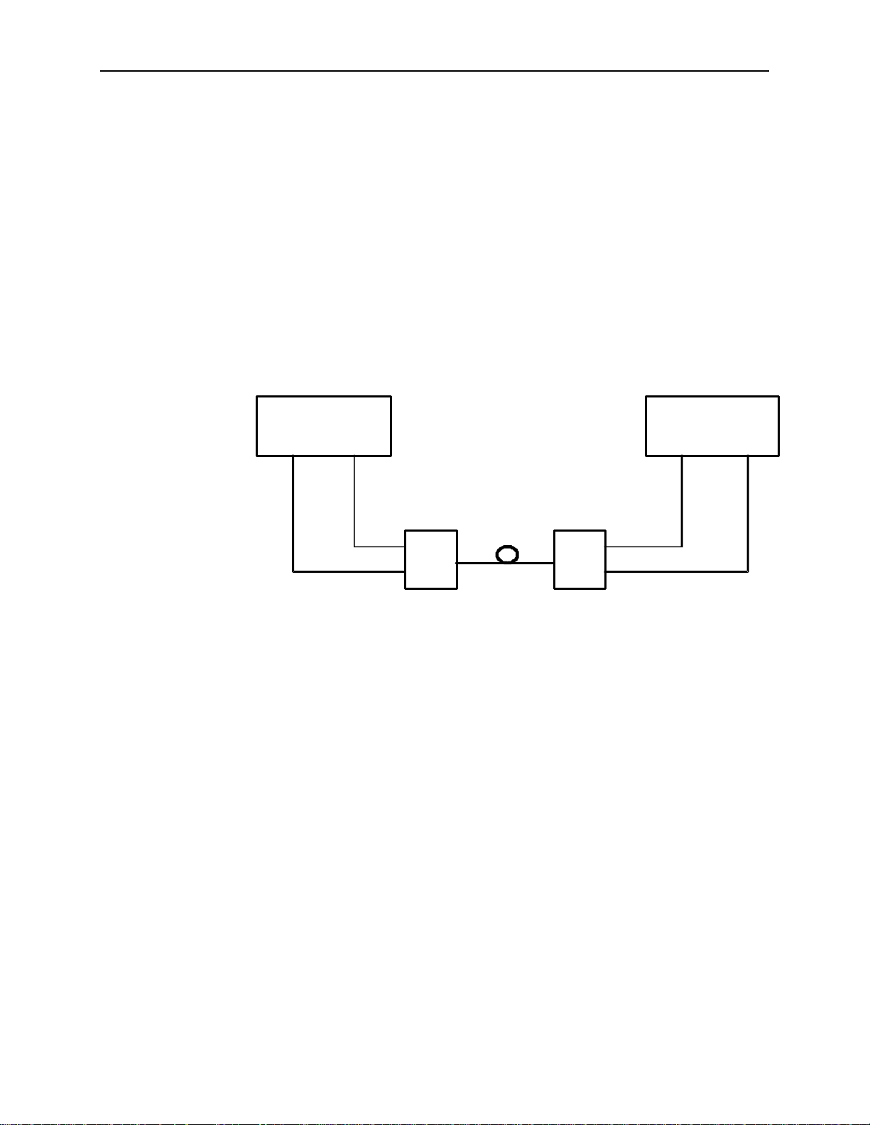
A typical BERT application, for example, would be to measure the error
performance of the electrical-to-optical (E/O) and optical-to-electrical (O/E)
output modules of a high-speed fiber optic transmission system (FOTS), as
shown in the figure below.
GB1400 Generator GB1400 Analyzer
CLOCK DATA
OUT OUT
E/O
O/E
CLOCK DATA
IN IN
Figure 2- 1. Example, BERT Application
The GB1400 is described as a serial BERT because it is designed to test one
digital path at a time. The term serial also distinguishes the GB1400 from
parallel BERTs, such as the Tektronix MB100, which is designed to test multiple
digital signal paths simultaneously.
The GB1400 Generator, also known as the transmitter or "Tx", can generate
various test patterns, including pseudo-random bit sequences (PRBS) and userdefined word patterns. The Generator output consists of a two level, non-return to
zero (NRZ) data signal and its associated clock signal, as illustrated in Figure
2-2. In the NRZ format, the data signal remains at either a logic "1" or logic "0"
level for the entire duration of each bit time slot, except for a small transition
period between time slots containing different data. The corresponding clock
signal is a nominal "square wave" whose frequency defines the bit rate of the test
signal.
2-2 GB1400 User Manual
Page 29
Functional Overview
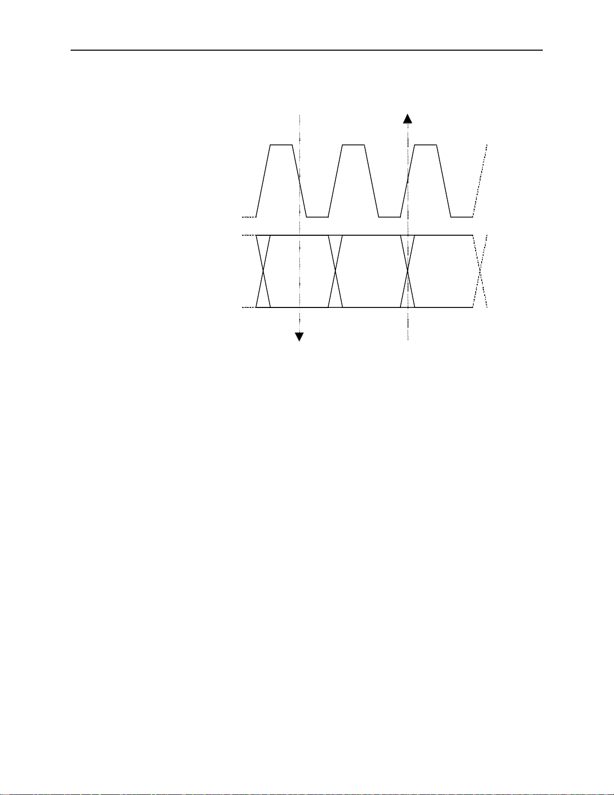
Falling edge of CLOCK
in middle of DATA "eye"
Rising edge of CLOCK Coincident with DATA transitions
CLOCK
DATA
Figure 2- 2. Nominal Generator NRZ Data and Clock Output
Waveforms
The nominal Generator clock/data phase relationship is fixed so that the falling
edges of the clock signal occur in the middle of bit time slots of the data signal.
The amplitude and baseline offset of the Generator's clock and data outputs are
adjustable to insure compatibility with a wide range of input circuit designs and
logic families including ECL, positive ECL, and GaAs.
The GB1400 Analyzer, also known as the receiver or "Rx", can terminate and
analyze the NRZ output of a digital device, module, or system being tested by the
GB1400 Generator or an equivalent signal source. The decision voltage or
threshold of the Analyzer DATA and CLOCK inputs can be adjusted to
accommodate different logic families. The Analyzer can also add a variable
amount of delay to the input data signal to accommodate different clock/data
phase relationships at the output of the device under test.
The primary measurements made by the GB1400 Analyzer are bit errors and bit
error rate.
GB1400 User Manual 2-3
Page 30
Functional Overview
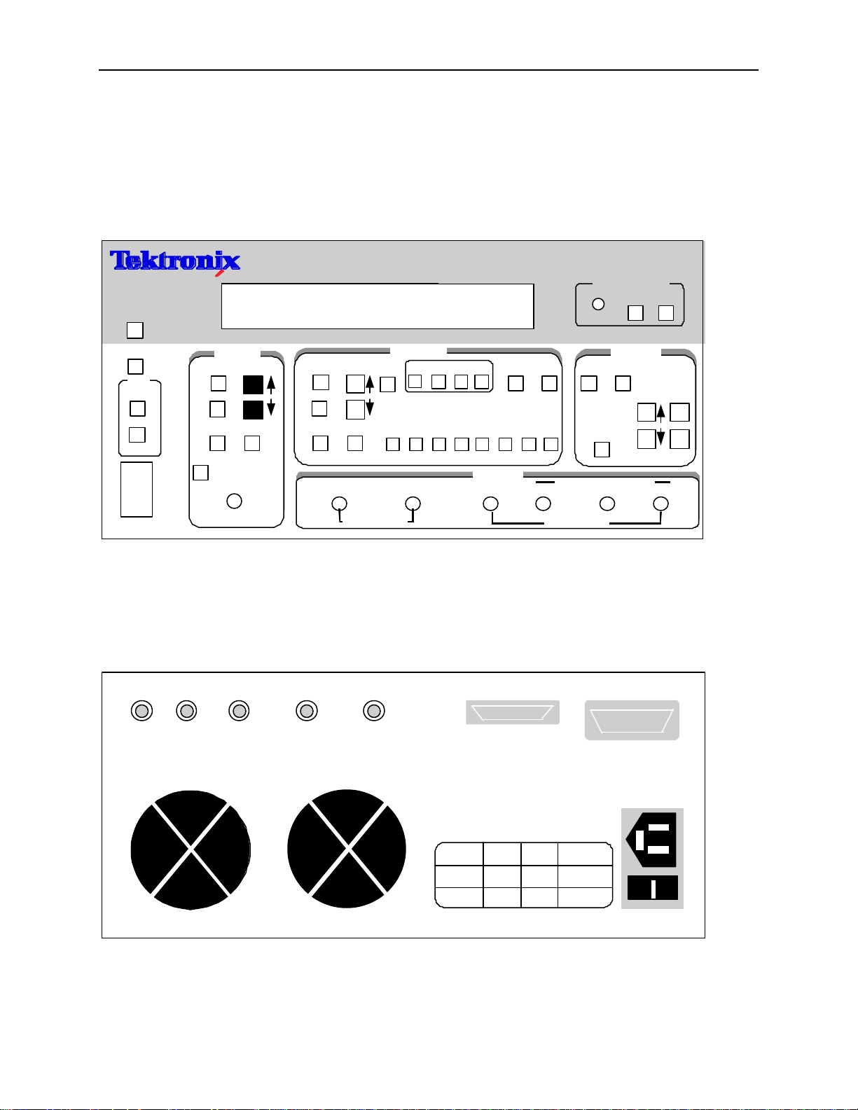
Controls, Indicators and Connectors
The first four figures in this section identify the controls, indicators and
connectors located on the front and rear panels of the GB1400 Generator (Tx)
and GB1400 Analyzer (RX).
VIEW
ANGLE
FREQUENCY (kHz)
MEMORY
PATTERN
gigaBERT1400 GENERATOR
OUTPUT
AMPL
OFFSET
ERROR INJECT
RATE SINGLE
PANEL
LOCK
GPIB
ADDR
LOCAL
REMOTE
POWER
ON
OFF
CLOCK
FREQUENCY
STEP
RECALL SAVE
EXT
INPUT
50 Ohm 2 V Max
PRBS
WORD
RECALL SAVE
PATTERN SYNC CLOCK/4 CLOCK
(2) (1)
50 Ohm SOURCE
PATTERN
WORD
F1 F2 F3 F4
LENGTH
BIT
MSB
1 2 3 4 5 6 7 8
(1) With Option 2, these outputs are 75 Ohm.
(2) With Option 5, the input is ECL levels only.
Figure 2- 3. Front Panel, GB1400 Generator (Tx)
PHASE A PHASE B CLOCK/2 ERROR INJECT DATA INHIBIT
CLEAR SET CLOCK DATA
OUTPUT
CLOCK
50 Ohm SOURCE
RS-232C
INVERT
DATA
(D-INV)
DATA
OUTPUT
AMPLITUDE
GPIB
OFFSET
DATA
WARNING
ELECTRICAL SHOCK HAZARD
THIS INSTRUMENT MUST BE GROUNDED
DO NOT OPEN INSTRUMENT REFER SERVICING TO
QUALIFIED PERSONNEL
DISCONNECT POWER CORD BEFORE REPLACING
FOR CONTINUED FIRE PRODUCTION REPLACE ONLY
INPUT MAX LINE
VOLTAGE RANGE POWER FUSE
115 90-132V 175W 5A SLOBLO
230 180-250V 175W 5A SLOBLO
AUTO SELECT FREQUENCY 47-63 Hz
FUSE
WITH SPECIFIED FUSES
AC-LINE
Figure 2- 4. Rear Panel, GB1400 Generator (Tx)
2-4 GB1400 User Manual
Page 31

VIEW
ANGLE
DELAY/
MEMORY
FREQUENCY (kHz) ERROR RATE TOTALIZE
Functional Overview
gigaBERT 1400 ANALYZER
ERROR HISTORY
SYNC LOSS
BIT
PHASE
POWER
CLEAR
PANEL
LOCK
GPIB
ADDR
LOCAL
REMOTE
POWER
ON
OFF
INPUT
DELAY
V-TERM V-THRESH
D-INV
DATA DATA
PRBS
WORD
RECALL SAVE
REFERENCE DATA CLOCK
(1) (2)(1)
PATTERN
WORD
LENGTH
MSB
1 2 3 4 5 6 7 8
EXT
(1) With Option 2, this input is 75 Ohm.
(2) With Option 5, the input is ECL levels only.
Figure 2- 5. Front Panel, GB1400 Analyzer (RX)
DATA
THRESHOLD
ERROR INHIBIT RZ ERROR
OUTPUT
PRINTER
F1 F2 F3 F4
CLK REF
BIT
ERROR DETECTION
SYNC
DISPLAY
CLEAR
AUDIO
VOL
MONITOR
CLOCK
50 Ohm SOURCE 50 Ohm, 1.5V MAX 50 Ohm, 2V MAX
CLEAR SET
CLOCK
PATTERN
RS-232C GPIB
RATE
SYNC
AUTO
SEARCH
LOCK
DISABLE
DATA
WARNING
ELECTRICAL SHOCK HAZARD
THIS INSTRUMENT MUST BE GROUNDED
DO NOT OPEN INSTRUMENT REFER SERVICING TO
QUALIFIED PERSONNEL
DISCONNECT POWER CORD BEFORE REPLACING
FOR CONTINUED FIRE PRODUCTION REPLACE ONLY
INPUT MAX LINE
VOLTAGE RANGE POWER FUSE
115 90-132V 175W 5A SLOBLO
230 180-250V 175W 5A SLOBLO
AUTO SELECT FREQUENCY 47-63 Hz
FUSE
WITH SPECIFIED FUSES
AC-LINE
Figure 2- 6. Rear Panel, GB1400 Analyzer (RX)
GB1400 User Manual 2-5
Page 32

Functional Overview
Display Formats
The normal display format for the Generator and Analyzer are explained below.
Note that the "normal" format is simply the format of the display when not in the
menu mode.
Generator (Tx) Display
The Generator has a two-line by 24-character high-contrast liquid crystal display
(LCD). The Generator display in its normal (non-menu) mode is illustrated in the
figure below.
Frequency (kHz) Pattern Output
1405000 PN23 2.00 V
FREQ 0 ERR OFF -1.00 V
Memory
Figure 2- 7. Generator Display in Its Normal (Non-menu) Mode
The function of each field in the normal Generator display format—that is the
format used when the Generator is not in the menu mode - is described below:
• The top left section of the Generator display is used to show the current
frequency of the internal clock in MHz. For example a display of
622.050 indicates a frequency of 622.050 MHz.
• The top middle section normally shows the current test pattern. For example
PN23 INV indicates that the current pattern is an inverted 2
• The top right section of the display shows the amplitude of the CLOCK or
DATA output, depending on which output control ( CLOCK or DATA) is
selected.
• The bottom left section of the Generator display may show either the
presently selected word memory (WORD 0 ... WORD 7) or the selected
frequency memory (FREQ 0 ... FREQ 9).
AMPL
OFFS
23
-1 PRBS.
• The bottom middle section of the display shows the currently selected
Generator error inject mode.
• The bottom right section of the Generator display will normally show the
baseline offset of the CLOCK or DATA output, depending on which output
control (CLOCK or DATA) is selected.
2-6 GB1400 User Manual
Page 33

Analyzer (RX) Display
Like the Generator, the Analyzer has a two-line by 24-character high-contrast
liquid crystal display (LCD).The Analyzer display in its normal (non-menu)
mode is illustrated in the figure below.
Frequency (kHz) Error Rate Totalize
1405000 5.0E-06 2410538
1.2 ns PN23 -0.05 V
Delay/ Memory
Figure 2- 8. Analyzer Display in Its Normal (Non-menu) Mode
Like the Generator, the Analyzer has a two-line by 24-character high-contrast
liquid crystal display (LCD). The function of each field in the normal Analyzer
display format -that is the format used when the Analyzer is not in the menu
mode -is described below:
Functional Overview
• The top left section of the Analyzer display is used to show the measured
frequency of the input clock signal in MHz. For example a display of
622.05 indicates a measured frequency of 622.05 MHz. Note that the
Analyzer frequency display contains five significant digits while the
Generator frequency display contains six. This is because the frequency
shown in the Analyzer display is a measurement result while the frequency
shown in the Generator display is an instrument setup which is known with
more precision.
• The top middle and top right sections of the display normally show measured
bit error rate and bit errors respectively. BER is expressed in exponential or
"E" notation. For example, a display of 1.5E-09 indicates a measured BER
of 1.5 x 10⁻⁹. The Analyzer calculates BER and counts bit errors in three
modes simultaneously: Window, Test, and Totalize. The symbol in front of
the BER field indicates which mode has been selected for display. Window
results are preceded by a blank space, that is no symbol. Totalize results will
be preceded by an ∞ (infinity) symbol. Test results will be preceded by a T,
U, or R depending on the selected test mode: timed, untimed, or repeat.
Refer to Chapter 4 for more information on displaying Analyzer results and
starting and stopping tests.
GB1400 User Manual 2-7
Page 34

Functional Overview
• The bottom left section of the Analyzer display can show the following setup
parameters: delay in nanoseconds for the DATA or REF DATA input; the
selected input termination (GND, -2V, or AC) for the CLOCK, DATA, or
REFERENCE DATA input, or the selected word memory (WORD 0 ...
WORD 7), Note that DATA input delay may be set manually by the user, or
automatically by the AUTO SEARCH feature.
To control the delay, termination or threshold settings for the DATA input,
make sure F2 and F3 LEDs are turned OFF.
Pressing F2 places the unit into CLOCK control (F2 LED illuminated). The
V-TERM key is redefined to allow control of the Input CLOCK Termination
voltage. The status of each key LED and LCD displayed value now reflects
the CLOCK Input signal.
Pressing F3 places the unit into REF Data control mode (F3 LED
illuminated). The Delay, V-TERM and V-THRS keys are redefined to allow
control of the Input REF DATA Delay, Termination Volga and Threshold.
The status of each key LED and LCD displayed value now reflects the REF
DATA Input signal.
• The bottom middle section of the display shows the currently selected
Analyzer pattern, for example PN23 indicates a 223-1 PRBS. This section
will also indicate when input pattern inversion is enabled by displaying INV
after the pattern name.
• The bottom right section of the Analyzer display shows the current value of
the input threshold in volts for the CLOCK, DATA, or REF DATA inputs.
Note that the CLOCK and DATA input thresholds may be set manually by
the user, or automatically by the AUTO SEARCH feature.
2-8 GB1400 User Manual
Page 35

Outputs and Inputs
This section introduces all inputs and outputs of the GB1400 Generator and
Analyzer. Unless otherwise indicated, all signal inputs and outputs are equipped
with SMA female connectors and have a nominal input or output impedance of
50 ohms. However, a 75 Ohm Option is available for both the Generator and
Analyzer which changes nominal impedance of key inputs and outputs to 75
ohms.
Note: The same term can be expressed three different ways.
Functional Overview
clock
DATA
= clock bar = NOT clock
= DATA BAR = NOT DATA
The front panel of the GB1400 Tx is divided into nine sections:
LCD Display Error Inject
Clock Pattern
Output Controls GPIB
Power Switch Output Connectors
Generator OUTPUT Connectors Section
The OUTPUT connectors section of the Generator front panel contains the
outputs listed below.
PATTERN SYNC CLOCK/4 CLOCK
OUTPUT
CLOCK
DATA
DATA
50 Ohm SOURCE
50 Ohm SOURCE
• CLOCK and DATA [outputs]: These two connectors comprise the main
test signal output of the Generator. DATA is the NRZ output of the pattern
generator and CLOCK is its corresponding clock signal. The amplitude and
baseline offset of CLOCK and DATA are variable. CLOCK and DATA may
be used to drive single-ended clock and data inputs, respectively.
• CLOCK-BAR and DATA-BAR [outputs]: These are complimentary
outputs to CLOCK and DATA. That is, CLOCK and CLOCK-BAR together
can drive a differential clock input, while DATA and DATA-BAR together
can drive a differential data input. These complementary outputs should be
terminated with a 50 Ohm load (or a 75 Ohm load if the 75 Ohm Option is
GB1400 User Manual 2-9
Page 36

Functional Overview
installed) when not in use—that is, when the Generator is driving singleended inputs.
• CLOCK/4 [output]: This is a clock signal at one quarter the frequency of
CLOCK. This output may be useful when observing generator outputs using
an oscilloscope that does not have the bandwidth to trigger on the CLOCK
output.
• PATTERN SYNC [output]: This is a pulse that occurs once per pattern
frame. This output may be useful as a trigger signal when observing the
Generator data output using an oscilloscope. The location of PATTERN
SYNC is fixed. A pulse is generated at the start of the pattern frame.
Generator CLOCK Section
Controls in the CLOCK section of the Generator are used to select clock mode
(internal or external) and to set up the instrument's internal clock. The CLOCK
section also contains the input connector for an external clock source. These
controls and input are introduced below.
FREQUENCY
STEP
RECALL
SAVE
EXT
INPUT
50 Ohm 2 V Max
(2)
• FREQUENCY: When this key is selected (LED on), the clock up/down
keys may be used to adjust the frequency of the internal Generator clock up
or down. Each press of the frequency up or down key will increment or
decrement frequency by the current step size.
• STEP: Select this key to adjust the frequency adjustment step size from
1 kHz to 100 MHz.
• SAVE: Use this key to save the present frequency into one of 10 frequency
memory locations.
• RECALL: Use this key to recall a previously saved frequency.
• EXT: Press this key to toggle between internal clock mode (LED off) and
external clock mode (LED on).
• INPUT: This is an input for an external clock source. A signal must be
provided to this input when clock mode is set to external. However, when
clock mode is internal, any signal appearing at this input will be ignored.
2-10 GB1400 User Manual
Page 37

Functional Overview
Generator OUTPUT Section
The controls shown below are used to set up the Generator's clock and data
outputs.
OUTPUT
CLOCK DATA
OFFSET
AMPLITUDE
INVERT
DATA
(D-INV)
• CLOCK: Use this key to select clock amplitude and offset set up mode.
• DATA: Use this key to select data amplitude and offset set up mode.
• AMPLITUDE (↑↑, ↓↓): Use these up/down keys to adjust clock or data
output amplitude.
• BASELINE OFFSET (↑↑, ↓↓): Use these up/down keys to adjust clock or
data baseline offset.
• INVERT DATA: Use this key to toggle between output data inverted (LED
on) and non-inverted (LED off) mode.
GB1400 User Manual 2-11
Page 38

Functional Overview
Generator Rear Panel
The rear-panel of the Generator contains the auxiliary signals, remote control,
and AC-power inputs shown below. See the appendix for instruction on how to
set up the RS-232 and GPIB ports, and general information on using external
controllers with the Generator.
PHASE A PHASE B CLOCK/2 ERROR INJECT DATA INHIBIT
• PHASE A: An SMA connector provides signal output for DATA Phase A.
This phase-shifted data pattern provides signals suitable for MUX/DEMUX
testing. Phase A/B outputs are half rate data patterns (alternating bits).
• PHASE B: : An SMA connector provides signal outputs for DATA Phase
B. This phase-shifted data pattern provides signals suitable for
MUX/DEMUX testing.
• CLOCK/2: : An SMA connector provides signal outputs for CLOCK/2.
• ERROR INJECT: An ECL signal applied to this input may be used to
control error injection when the Generator is in the external (EXT ERR)
injection mode. One error will occur for each rising edge of this signal.
• DATA INHIBIT: An ECL signal applied to this input may be used to
asynchronously gate off the data outputs of the Generator.
• RS-232C [input/output]: A two-way serial port that may be connected to
an external controller or serial printer.
• GPIB [input/output]: An IEEE-488 standard I/O port that may be
connected to a GPIB compatible controller. This port is not compatible with
stand-alone GPIB printers.
• AC LINE [power input]: This is the AC power input connector for the
Generator.
Changing the Line Fuse
1. Disconnect the AC line cord.
2. Slide the fuse cover upwards and remove the fuse.
3. Install the correct line fuse into the holder.
115 VAC 5A, Slo-Blo
230 VAC 5A, Slo-Blo
4. Close the fuse cover.
5. Plug in the line cord.
Allow at least two inches of clearance for the rear panel fan opening and at least
one inch of clearance for the top of the unit. This assures proper cooling of the
unit. Do not operate the Generator on its rear side.
2-12 GB1400 User Manual
Page 39

Functional Overview
Analyzer INPUT Section
The INPUT section of the Analyzer front panel contains the test signal NRZ data
and clock inputs shown below.
DATA
DATA
REFERENCE DATA CLOCK
CLOCK
• CLOCK and DATA [inputs]: These inputs comprise the main test signal
input to the Analyzer. DATA is the main NRZ data input to the Analyzer
pattern detector and CLOCK is its corresponding clock signal. Both inputs
have selectable input terminations. In addition, a variable amount of delay
may be added to the DATA input to properly phase-align the clock and data
signals. CLOCK and DATA may be used to terminate singled-ended clock
and data outputs, respectively.
For single-ended applications, the DATA input threshold is programmable.
This requires an external cable connection from the rear panel DATA
THRESHOLD output to the unused DATA input. Only the unused
"DATA-BAR" input needs the threshold signal. The CLOCK input is selfbiasing for single-ended applications.
• CLOCK-BAR and DATA-BAR [inputs]: These are complimentary inputs
to CLOCK and DATA. That is, CLOCK and CLOCK-BAR together
comprise a differential clock input, while DATA and DATA-BAR together
comprise a differential data input. When the Analyzer is connected to
singled-ended clock and data signals, these inputs are not used.
Note: In DIFFERENTIAL applications, the programmed threshold voltage is
not used.
• REFERENCE DATA [input]: This is an input for a reference data signal.
When the external reference mode is selected (LED in EXT key is on), the
signal appearing at the REF DATA input will be used as the reference signal
to perform bit error analysis instead of a (reference) pattern generated by the
Analyzer's error detection circuit. Note that REF DATA uses the same clock
signal as DATA, however different amounts of delay can be added to the
DATA and REF DATA inputs to account for phase differences between the
two signals.
GB1400 User Manual 2-13
Page 40

Functional Overview
Analyzer MONITOR Section
The MONITOR section of the Analyzer front panel contains the auxiliary outputs
shown below. These outputs may be used to monitor the test signal as seen by
the Analyzer.
PATTERN
SYNC
MONITOR
CLOCK
50 Ohm SOURCE
DATA
• CLOCK [output]: A buffered copy of the clock signal received by the
Analyzer.
• DATA [output]: A regenerated (re-clocked) version of the data signal
received by the Analyzer.
• PATTERN SYNC [output]: A train of pulses that occur once per pattern
frame. This output may be used to trigger an oscilloscope to view the
beginning (first bit/byte) of the data pattern.
2-14 GB1400 User Manual
Page 41

Functional Overview
Analyzer Rear Panel
The rear-panel of the Analyzer contains the auxiliary signal, remote control,
printer, and AC-power inputs shown below. See the appendix for instruction on
how to set up the RS-232 and GPIB ports, and general information on using
printers and external controllers with the Analyzer.
DATA
THRESHOLD
ERROR INHIBIT RZ ERROR
OUTPUT
• DATA THRESHOLD OUTPUT: The programmed DATA threshold
voltage is set via the front panel. Connect to DATA BAR input for singleended applications. Requires external cable connection.
• ERROR INHIBIT INPUT: An ECL signal applied to this input may be
used to asynchronously gate on/off the error detection function of the
Analyzer. That is, while the signal at this input is low, errors are counted.
While it is high, error counting is inhibited.
• RZ ERROR OUTPUT: This is an ECL output signal. One pulse will be
generated at this output for each bit error detected. May be connected to an
external recording device, for example, to log the exact times that errors
occur.
• PRINTER [output]: A one-way port that may be connected to a "parallel
printer"—that is, any printer compatible with the parallel port (LPT1 etc.) of
an IBM-compatible PC.
• RS-232-C [input/output]: A two-way serial port that may be connected to
an external controller (e.g. a PC or workstation) or to a serial printer.
• GPIB [input/output]: A two-way, IEEE-488 compatible I/O port that may
be connected to an external controller via a GPIB cable.
PRINTER
RS-232C GPIB
Changing the Line Fuse
1. Disconnect the AC line cord.
2. Slide the fuse cover upwards and remove the fuse.
3. Install the correct line fuse into the holder.
115 VAC 5A, Slo-Blo
230 VAC 5A, Slo-Blo
4. Close the fuse cover.
5. Plug in the line cord.
Allow at least two inches of clearance for the rear panel fan opening and at least
one inch of clearance for the top of the unit. This assures proper cooling of the
unit. Do not operate the Analyzer on its rear side.
GB1400 User Manual 2-15
Page 42

Functional Overview
Connectors, Terminations, and Levels
Tables 2-1 and 2-2 below summarize the physical interface characteristics of all
GB1400 Generator and Analyzer inputs and outputs.
Table 2-1. Generator (Tx) Inputs and Outputs
Connector Label Signal Type Location Connector
Type
DATA output OUTPUT section SMA,
female
CLOCK output OUTPUT section SMA,
female
DATA-BAR output OUTPUT section SMA,
female
CLOCK-BAR output OUTPUT section SMA,
female
CLOCK/4 output OUTPUT section SMA,
female
PATTERN SYNC output OUTPUT section SMA,
female
Impedance, amplitude,
and offset
50 Ohm, see NOTE 1,
variable amplitude and
offset
50 Ohm, see NOTE 1,
variable amplitude and
offset
50 Ohm, see NOTE 1,
variable amplitude and
offset
50 Ohm, see NOTE 1,
variable amplitude and
offset
50 Ohm, 200mV into 50Ω
50 Ohm, 200mV into 50Ω
CLOCK INPUT input CLOCK section SMA,
female
DATA INHIBIT input rear panel BNC,
female
ERROR INJECT input rear panel BNC,
female
RS-232 I/O rear panel 25 pin, D
type
GPIB I/O rear panel GPIB IEEE-488 standard levels
50 Ohm, 2V max, see
NOTE 2
50 Ohm to -2V, ECL
50 Ohm to -2V, ECL
RS-232C standard levels
and impedance
and impedance
Note 1: A 75-Ohm version of the GB1400 is an option.
Note2: BURST Mode units require ECL-level inputs and are terminated with 50-Ohms to -2V.
2-16 GB1400 User Manual
Page 43

Table 2-2. Analyzer (RX) Inputs and Outputs
Functional Overview
Connector Label Signal
Type
DATA/DATA BAR Input INPUT SMA, female 50 Ohm, see NOTE 1, variable
CLOCK/CLOCK
BAR
REF DATA Input INPUT SMA, female 50 Ohm, ECL, variable delay,
PATTERN SYNC output MONITOR SMA, female
CLOCK output MONITOR SMA, female
DATA output MONITOR SMA, female
ERROR INHIBIT
INPUT
RZ ERROR
OUTPUT
Input INPUT SMA, female 50 Ohm, see NOTE 1, fixed
input rear panel BNC, female 50 Ohm, ECL
output rear panel BNC, female
Section Connector
Type
Impedance, threshold, and delay
threshold and delay. Selectable
termination: GND, -2 V, AC
threshold. Selectable termination:
GND, -2 V, AC
selectable termination GND, -2V,
AC
50 Ohm, 200mV into 50Ω
50 Ohm, 200mV into 50Ω
50 Ohm, 200mV into 50Ω
50 Ohm, 200mV into 50Ω
PRINTER output rear panel 25-pin, D male Compatible with PC parallel printers
RS-232C I/O rear panel 25-pin, D male RS-232 levels and impedance
GPIB I/O rear panel GPIB IEEE-488 standard levels and
impedance
Note 1: A 75-Ohm version of the GB1400 is an option.
GB1400 User Manual 2-17
Page 44

Functional Overview
Controls and Indicators
All of the controls, indicators, inputs, and outputs found on the Generator or
Analyzer front or rear panels are discussed in the following section.
Power Switches
The ON/OFF power switch is located on the left side of the test instrument below
the LCD screen. The power switch switches the 120/240 VAC to the system
power supply. When off, a Battery backup circuit powers the non-volatile RAM.
Unit Mounting
The GB1400 is designed to be placed: (1) flat on a level surface, capable of
supporting its weight, or (2) angled from the surface with the rotating carrying
handle. To change the handle's orientation, press both handle-locking buttons
(located at the hubs of the handle), rotate the handle to the desired angle, and
release the buttons. The handle will click into a locked position. Assure that the
handle is locked before placing the unit on a work surface. A Rack mounting
option is available for installation of the unit into a 19" rackmount. The rack
height for the GB1400 is 7 inches (four RMU).
Unit Cooling
The rear panel fan openings must be kept clear for proper cooling of the unit.
Allow a minimum of two (2) inches of rear panel clearance, and one (1) inch of
top clearance, while operating the unit.
View Angle and Panel Lock Keys
The PANEL LOCK and VIEW ANGLE keys are located near the top, left side of
the front panel.
• VIEW ANGLE: Use this key to select the optimum LCD viewing angle.
• PANEL LOCK: Use this key to "lock" and "unlock" the front panel. While
the front panel is locked, all keys that can cause setup changes are disabled.
This feature can help prevent accidental loss of data when performing longterm or critical tests.
RESET to Factory Default
To return the Generator or Analyzer to factory default settings, turn the
instrument OFF and then re-power it while pressing and holding the VIEW
ANGLE, MSB 1, and (PATTERN) CLEAR keys at the same time. Release these
keys after the message Default Setup appears in the display.
2-18 GB1400 User Manual
Page 45

Functional Overview
GPIB Section Controls
There are two keys in the GPIB section:
• ADDR: Key used to set GPIB address in the range 0 to 30.
• LOCAL: The LED in this key indicates whether the instrument is in the
local mode (LED off) or remote mode (LED on). If the LED is on, you can
return the instrument to local mode by pressing the LOCAL key.
Note that these two keys are used only when operating the instrument via its
GPIB port. For more information on the GPIB port and remote control in general,
see the appendix. For detailed descriptions of all remote commands, see the
appendix.
GB1400 User Manual 2-19
Page 46

Functional Overview
Pattern Controls and Function Keys
The PATTERN section of both the Analyzer and Generator front panels contains
two basic types or groups of controls: "pattern" and "function". The four
function or "soft" keys —F1, F2, F3, and F4—have different functions depending
on the current mode of the instrument. A primary function of these controls is to
access and navigate the menu system. Pattern controls, which includes all other
controls in the PATTERN section, are used to select edit, save, and recall test
patterns.
WORD
PRBS
LENGTH
F1 F2 F3 F4
CLEAR SET
WORD
RECALL
SAVE
MSB
1 2 3 4 5 6 7 8
CLK REF
• PRBS: Press this key, and then the pattern up/down keys to select a PRBS
pattern.
• WORD: Press this key either to select a word or ROM pattern or to edit the
current word pattern.
• SAVE and RECALL : Use these keys to save and recall user-created word
patterns to and from non-volatile memory. The standard GB1400 can store
up to ten 16-bit or short word patterns. When equipped with the 1-Mbit
option, the GB1400 Generator and Analyzer can store up to ten (10) 65-kbit
patterns, depending upon the buffer size set for word memory.
• WORD LENGTH: Press this key and then the up/down keys, to adjust the
length of the current word pattern.
• (↑↑,↓↓): These are the pattern up/down keys. Their effect depends on which of
the above pattern keys has been selected.
• MSB 1 to 8: Use these keys to edit the displayed byte in the current word
pattern. Each key will toggle one bit in the displayed byte.
• CLEAR: Pressing this key forces all bits in the displayed byte to 0.
• SET: Pressing this key forces all bits in the displayed byte to 1.
2-20 GB1400 User Manual
Page 47

Functional Overview
Function (Soft) Keys (F1, F2, F3, and F4)
Menu Functions: The primary use of the function keys in the Generator and
Analyzer is to access and navigate each instrument's menu system. F1 may be
thought of as the main menu key. Pressing F1 will display the instrument's first
level menu. Once inside the menu system, you may use the F1, F2, F3, and F4
keys to select different menus, or to make choices within a selected menu. Note
that pressing the F1 key enough times will always get you out of the system. See
Chapter 3 - Reference for an explanation of each Generator and Analyzer menu.
Analyzer Inputs
These function keys provide signal inputs and control of parameters (Input
Termination, Threshold, Logic Polarity and Data/Clock Phase Delay) for DATA,
Ref DATA, and CLOCK.
Selecting DELAY, V-TERM or V-THRS permits the INPUT Up/Down keys to
vary the Input parameters for DATA, as described below. Holding the Up/Down
key repeats the function five times a second.
Function key F2 (CLOCK) permits the V-TERM key to vary only the Input
termination parameters for CLOCK.
Function key F3 (Ref DATA) permits the DELAY, V-THRS, and V-TERM keys
to vary the Input parameters for Reference DATA.
DELAY - Pressing DELAY selects Input Data Delay adjust mode. The Input
Data signal can be delayed over the range 0.0 nS to 3.9 nS in sub-nanosecond
steps. The delay is modified with the INPUT Up/Down keys. The current Delay
is displayed on the lower left side of the LCD.
An illuminated Delay LED light indicates that the unit's DELAY can be modified
by the Up/Down arrow keys.
V-TERM - Pressing V-TERM selects V-termination mode. The input
termination voltage for Input Data is selectable between GND, -2.0V, and AC.
-2.0V mode provides active termination for ECL and GaAs signals. AC mode
allows RF termination.
An illuminated V-TERM LED light indicates that the input termination can be
modified by the Up/Down arrow keys.
V-THRS - Pressing V-THRS selects V-Threshold mode. The Input Data
threshold is variable over the range of -1.5V to +1V in 50 mV steps. The
currently selected threshold voltage is displayed in the lower right side of the
LCD display.
An illuminated V-THRS LED light indicates that the threshold voltage can be
modified by the Up/Down arrow keys.
The Data threshold voltage is available at the Analyzer rear panel SMA jack
labeled DATA THRESHOLD.
Print Setup Function (Analyzer only): You can print a report showing the
current setup of the Analyzer by pressing the F4 key. This function, however, is
not active in the menu mode.
GB1400 User Manual 2-21
Page 48

Functional Overview
Generator ERROR INJECT Section
Controls in the ERROR INJECT section are used to set up the Generator's error
injection function.
ERROR INJECT
RATE SINGLE
• RATE: Press this control one or more times to select an internal error inject
rate, or the external error inject mode.
• SINGLE: When the error inject function is set to single (ERR OFF), press
this key to inject single errors. Or, when the error inject function is set to an
internal rate, or to external, use this key to turn error injection off. Note that
you could then press the RATE key to turn error injection back on at the
same rate as before.
• Error Inject (LED): The LED in the ERROR INJECT section will flash
once for each injected error.
2-22 GB1400 User Manual
Page 49

Functional Overview
Analyzer INPUT Section
The controls shown below are used to set up the Analyzer clock and data inputs.
INPUT
DELAY
V-TERM V-THRESH
D-INV
DATA DATA
50 Ohm, 2V MAX
REFERENCE DATA CLOCK
(1)
EXT
CLOCK
(2)(1)
50 Ohm, 1.5V MAX
• DELAY: Press this key to add delay to the DATA or REF DATA inputs to
adjust the clock/data phase relationship. Note that the Auto_Search function
will automatically set data delay to a value which provides the maximum
noise immunity, that is so that the active (falling) edge of the clock falls in
the middle of data bit time slots.
• V-THRESH: Press this key to set the input decision threshold for the
DATA and REF DATA inputs. Note that threshold does not apply when
differential operation is selected. Function keys F2 and F3 are OFF when
programming DATA. Function key F3 is ON when programming REF
DATA.
• V-TERM: Press this key to select the input terminations for the DATA,
CLOCK, or REF DATA inputs. Available selections are: (GND, -2 V, or
AC). See table below.
• D-INV: Press this key to select either the data non-inverted (LED off) or
data inverted (LED on) mode.
• EXT: This is an input for an external data reference signal.
NOTE: Use the F2 and F3 function keys to determine which input will be
affected by the DELAY, V-THRESH, and V-TERM controls as follows:
F2 F3 Affected Input Allowable Control
off off DATA V-TERM, V-THRESH, DELAY
on off CLOCK V-TERM only
off on REF DATA V-TERM, V-THRESH, DELAY
on on not allowed
GB1400 User Manual 2-23
Page 50

Functional Overview
SYNC LOSS
PHASE
Analyzer Error History Section
BIT
POWER
SYNC LOSS
BIT
PHASE
POWER
CLEAR
The SYNC LOSS LED is lit when the unit is not synchronized, it will remain lit
until cleared by the user.
The BIT LED is lit when bit errors occurs, and remains lit until it is cleared by the
user.
The PHASE LED is lit when the guaranteed setup or hold time of the GB1400
input decision circuit is violated. This indicates to the user that the errors that are
occurring may be due to input clock/data timing or signal level.
The POWER LED is lit when the unit powers up. It remains lit until it is cleared
by the user. It is used to indicate that the unit lost power during a long term
(overnight) test.
2-24 GB1400 User Manual
Page 51

Functional Overview
Analyzer ERROR DETECTION Section
The ERROR DETECTION section contains test setup and display controls.
ERROR DETECTION
DISPLAY
CLEAR
AUDIO
VOL
RATE
DISPLAY SELECT: Use this control to select which results are displayed in
the Bit Error Rate (BER) fields. The options are Window, Totalize, or Test.
• CLEAR: Press this key to clear previous results and to start/stop timed tests.
• AUDIO VOL (↑↑, ↓↓): Use these keys to increase or decrease the volume of
the Analyzer's error beeper function.
SYNC
AUTO
SEARCH
LOCK
DISABLE
• AUDIO RATE (↑↑, ↓↓): Use these keys to increase or decrease the error rate
threshold of the beeper function. Selections are 1E-x, where x = 2, 3, ... 16.
Analyzer SYNC Controls
The ERROR DETECTION section contains the following SYNC controls which
are used to set up the Analyzer's automatic synchronization functions:
• AUTO SEARCH: Press this key to enable (LED on) or disable (LED off)
AUTO SEARCH. With AUTO SEARCH enabled, each time BER goes above
the synchronization threshold (LOCK LED turns off) the Analyzer will
automatically attempt to:
1. set the decision level for the DATA inputs,
2. set input DATA delay,
3. determine which PRBS or short word pattern is being received, and
4. determine if the pattern is inverted or not.
• DISABLE: Use this key to enable or disable automatic pattern re-
synchronization. If DISABLE is off, then the Analyzer will automatically
try to resynchronize its pattern detector (by looking for a new pattern
alignment) when BER goes above the current synchronization threshold. If
DISABLE is on, the Analyzer will not attempt to resynchronize regardless of
the BER. This allows for very high BER measurements.
This key controls the "clock slip" operation of the BERT. An illuminated
DISABLE LED indicates the synchronization (clock slip) circuit is disabled.
• LOCK (indicator): This indicator turns ON when BER is less than the
current synchronization threshold, and OFF when BER is greater than or
equal to this threshold.
GB1400 User Manual 2-25
Page 52

Functional Overview
Burst Mode Option
The standard GB1400 operates over a clock frequency range of 1 Mbit/s to 1400
Mbit/s. The GB1400 Tx has an internal clock source that has a range of 1 MHz to
1400 MHz. It also has a provision for using an external clock source of the same
frequency range. When using the external clock source, it must be applied
continuously without interruption. The GB1400 RX also requires that, at all
times during the test, a clock signal within the 1 Mbit/s to 1400 Mbit/s frequency
range be continuously applied. If the external clock signal should be removed , or
go below 1 MHz for any reason during the test, the RX will register OUT OF
SYNC as soon as the clock signal is reapplied. This condition will initiate a
resynchronization of the receiver and restart any tests.
For the Burst Mode option, the GB1400 RX has been modified to work normally
or in Burst Mode from 150 kHz to the normal 1400 MHz upper limit. The RX
CLOCK and CLOCK BAR inputs have been modified for DC operation. This
modification requires the removal of any blocking capacitors in the input path.
The removal of the capacitors limits the allowable input signal to ECL levels
only. Levels other than ECL may damage the input circuitry. The three standard
clock input termination selections of GND, AC, and -2V are still present.
Note: The Clock may be used either differentially or single-ended. To use a
single-ended clock input, connect the ECL clock input to the CLOCK input
connector. Select the -2V input termination, and connect DC bias voltage of -1.3
VDC to the CLOCK BAR input connector.
These and other changes will now allow the receiver to maintain synchronization
whenever CLOCK and DATA are synchronously stopped and started during a
test pattern, providing there has not been a bit slip between CLOCK and DATA.
In both the Tx and RX, there can be any length of time that both CLOCK and
DATA are off, and the minimum CLOCK/DATA applied can be as low as a
single cycle, providing the minimum of 714 pS and maximum of 667 µs clock
period restrictions are observed.
Similar Tx circuit changes allow the Tx DATA and CLOCK outputs to follow,
cycle by cycle, the input from a bursted External Clock Input. This means that
the Tx can be used in a start-stop, or "Burst Mode".
For every clock cycle into the External Clock Input, there will be the same
number of clock cycles and data bits output through the clock and data outputs.
The time between clock cycle inputs is unrestricted and can be any length of
time. The number of clock cycles can be any number from continuous to a single
cycle. During the time there is no clock input to the External Clock Input, the
internal code generator is idle (not running). Each clock cycle steps the code
generator by one bit. Clock cycle period must not be more than 667 µs (150
kHz) nor less than 714 pS (1400 MHz).
2-26 GB1400 User Manual
Page 53

Functional Overview
Burst Mode Usage
The Burst Mode option of the GB1400 will find usage in applications where
traditional BERTs cannot operate. Traditional BERTs require a continuous
CLOCK and DATA signal with no interruption. Should interruptions occur, the
RX will resynchronize or indicate errors that actually did not occur due to the
asynchronous re-start. The BURST MODE allows operation with a noncontinuous clock.
There are communications and telemetry systems that do not necessarily send
data continuously. These systems send data in "bursts" with variable times of
inactivity between bursts. Traditional BERTs cannot accurately check these
systems, especially if the bursts are of short duration. A traditional BERT may
require more bits than are available in the burst to (re)synchronize. Even if the
bursts are large, many bits in the burst would not be checked during the
(re)synchronization procedure.
In Burst Mode, the GB1400 RX will follow the input CLOCK and DATA
without regard for inactive time between bursts. The only requirement is that
there be no bit slips between the CLOCK and DATA at the Tx or UUT and there
be a clock cycle for every DATA bit received.
See figures on the next page for Transmit and Receive Operation with Burst
Mode.
Specifications for Burst Mode
• Maximum time between bursts - no restriction
• Minimum time between bursts - one clock period
• RX Clock Input - ECL level only; User-selectable termination 50 Ohms to
-2V should be used. Minimum rate during burst - 150 kbit/s; Maximum rate
during burst - 1400 Mbit/s
• RX Auto Search restriction - Below 500 kbit/s, the Auto Search function can
take a very long time due to code word search. Finding both Threshold and
Delay is rapid, but Data Pattern search is lengthy. Because of this, the user
should use Manual Search Mode to keep synchronization time as low as
possible.
• Restriction on other options - None
GB1400 User Manual 2-27
Page 54

Functional Overview
Undefined Time Undefined Time
Ext Clk In ……………….. ………………..
Clk Out ……………….. ………………..
Data Out ……………….. ………………..
Data Value 1 0 1 1 0 0
Figure 2- 9. Transmitter Burst Mode Option
[ Sync Time ] [ Measurement
A
DATA
Sync
Attained
Undefined Time Sync Attained
B
DATA
C
DATA
|------| |
[Msmt ] [ Sync ] [Measurement ]
Start Resync
[Msmt ] [Measurement ] [Msmt ]
Figure 2- 10. Receiver Burst Mode Operation
2-28 GB1400 User Manual
Page 55

PECL Option for GB1400 Tx
The PECL option is available for the GB1400 Tx only. The PECL option for the
GB1400 Tx is a modification that allows for an increased OFFSET RANGE for
the clock and data outputs, so that the user will be able to generate PECL levels
for testing in a PECL environment. PECL is defined as ECL operating +5.0 V
above ground.
Example:
ECL Levels PECL Levels
VOH ≈ -.9V VOH ≈ +4.1V
VOL ≈ -1.8V VOL ≈ +3.2V
VBB ≈ -1.35V VBB ≈ +3.65V
VTT ≈ -2.0V VTT ≈ +3.0V
The GB1400 front panel displays, the clock and data amplitude and offset based
on a load of 50 Ohms to ground.
Functional Overview
The inverted output circuit is identical to the true output circuit.
In the PECL system, Vtt = +3.0V, therefore, the resulting GB1400 Tx signal will
be shifted by +1.5V. To get PECL levels at the GB1400 Tx output, set the unit
levels as follows:
Display Setting Resulting PECL Levels
(50 Ohms to +3.0V)
AMP = .90V
OFFSET = +1.7V
GB1400 User Manual 2-29
VOH ≈ +4.10V
VOL ≈ +3.20V
Page 56

Tutorial
Basic BERT testing with the GB1400
A critical element in digital transmission systems is how error-free its
transmissions are. This measurement is made by a bit-error-rate tester (BERT).
The GB1400 Generator (Tx) and Analyzer (Rx) are designed to operate at bit
rates up to 1400 Mb/s. These portable instruments provide PRBS or User
Defined Patterns (up to 1Mbit deep) for high speed BERT testing.
Objective of Tutorial
Understand GB1400 instrument setup for BER testing using PRBS patterns.
Procedure
This tutorial programs the GB1400 Generator to provide PRBS clock and data
signals for the Analyzer. Using AUTO-SEARCH features, the Analyzer will
synchronize to the incoming PRBS test pattern. Bit Error Rate (BER)
measurements will be performed on both good (error-free) and bad (user injected
faults) data streams.
Key Feature of Tutorial
This lab demonstrates the use of AUTO-SEARCH Synchronization.
Equipment Required
Description Qty Part Number Source
GB1400 Generator 1 GB1400 Tx Tek
GB1400 Analyzer 1 GB1400 Rx Tek
50Ω Coax SMA cables, 1 meter
length, male to male
3 174-1341-00 Tek
GB1400 User Manual 2-30
Page 57

DATA
CLOCK
Tutorial
Instrument Connections and Controls
Data Threshold connection (required
for single-ended signals)
GB1400 Analyzer (Receiver)
GB1400 Generator (Transmitter)
CLOCK
CLOCK
DATA
DATA
1. Setup units with default settings
Note: Resetting the unit to factory defaults is used infrequently. It helps simplify
instructions on this beginners lab. A customer would not normally do this as
they would lose their stored setups.
To reset the units to their factory default setting, you must hold down three
separate keys while turning on the front panel power switch. Power the
Generator while pressing and holding its VIEW ANGLE, MSB 1 and (PATTERN) CLEAR
keys simultaneously. Release the key after the message Default Settings appears in
the display. Repeat this procedure with the Analyzer. This will force both the
Generator and Analyzer to power up using factory default settings.
GB1400 User Manual 2-31
Page 58

Tutorial
2. Connect the Generator to the Analyzer.
Connect the generator and analyzer as shown below. The generator CLOCK output
connects to the analyzer CLOCK input. The generator DATA output connects to the
analyzer DATA input. The rear panel THRESHOLD output on the Rx connects to the
Receiver NOT-DATA input on the front panel. Terminate the generator NOT_CLOCK
and NOT_DATA signals with the 50Ω terminators located on the front panel of the
generator.
rear panel
threshold output
GB1400 TX GB1400 RX
clk clk data data data data clk clk
data
clock
Note: Do not mix up the clock, not_clock, data, and not_data signals or tutorial
results will be different.
3. Setup Generator for PRBS-23 Mode.
Locate the controls in the OUTPUT box of the Generator. Setup the Generator
clock and data outputs as follows:
Set this parameter …to this value …using this procedure.
DATA amplitude. 1 volts Press the DATA key. The LED within the switch
should be lit.
Press AMPLITUDE up/down keys until data
amplitude is set to 2.00V.
DATA baseline offset -0.5 volt Press BASELINE OFFSET up/down keys until
data baseline offset is set to -0.50V.
CLOCK amplitude 1 volts Press CLOCK. (the LED within switch should be
lit).
Press AMPLITUDE up/down keys until clock
amplitude is set to 2.00V.
CLOCK baseline
offset
-0.5 volt Press BASELINE OFFSET up/down keys until
clock baseline OFFSET is set to -0.50V.
2-32 GB1400 User Manual
Page 59

B. Locate the controls in the PATTERN box of the Generator. Make sure the
PRBS button is enabled (the LED inside this switch should be ON). Set the
Generator pattern to a 2
Set this parameter …to this value …using this procedure.
PRBS type PN 23 Press pattern up/down arrow keys until
23
-1 bit PRBS as follows:
PATTERN is set to PN 23
C. Locate the controls in the ERROR INJECT box of the Generator. Verify
that the Generator ERROR RATE GENERATOR is OFF (the LED within the switch should
be OFF). If the LED in the error inject RATE key is ON, then press RATE one or
more times until it turns off.
4. Setup Analyzer for “AUTO-SEARCH” Operation.
A. Locate the controls in the SYNC box of the Analyzer. Verify that the
Analyzer AUTO SEARCH function is ENABLED. The LED in the AUTO SEARCH key
should be ON. If the LED is OFF, press the AUTO SEARCH function one time until
the LED is ON. At this point, verify that the green LOCK LED is ON.
Tutorial
B. Locate the controls in the ERROR DETECTION box of the Analyzer. Zero
all Analyzer error counts by pressing the CLEAR key. Confirm that the number of
errors and the error rate were reset to 0 (note: error rate will start changing as
more and more bits are received. After several minutes of operation, the error
rate should reach 0.0E-9 ⇒ 0.0E-10 ⇒ 0.0E-11 and on).
C. Locate the controls in the ERROR HISTORY box of the Analyzer. Reset all
Analyzer history LEDs by pressing this CLEAR key. Confirm that all ERROR
HISTORY LED’s are turned OFF.
D. Locate the controls in the ERROR INJECT box of the Generator. Verify the
GB1400 Analyzer can detect errors by pressing the Generator ERROR INJECT
SINGLE key several times. Verify that the number of errors count displayed by
the Analyzer increments each time the Generator SINGLE key is pressed.
In effect you are now performing a bit error rate test on the test cables connecting
the gigaBERT1400 Generator and Analyzer. In an actual BER test,
gigaBERT1400 Generator clock and data outputs would be connected to inputs
on a "device under test" (DUT) while gigaBERT1400 Analyzer inputs would be
connected to outputs on the DUT.
GB1400 User Manual 2-33
Page 60

Tutorial
5. Change the PRBS pattern type
These steps demonstrate one of the many benefits of our Full-Featured AutoSearch algorithm - automatic synchronization to the incoming signal by selecting
the correct PRBS test pattern.
A. Locate the controls in the PATTERN box of the Generator. Make sure the
PRBS button is enabled (the LED inside this switch should be ON). Set the
Generator pattern to a 2
Set this parameter …to this value …using this procedure.
PRBS type PN 7 Press pattern up/down arrow keys until
7
PRBS as follows:
PATTERN is set to PN 7
As the PRBS pattern type is changed, the Analyzer will start searching for a
match. You should see the BIT, PHASE, and SYNC LOSS LED’s turn ON in the Error
History section of the Analyzer. While the Analyzer is searching for the correct
PRBS type, the LOCK LED in the Error Detection Section should turn OFF. When
synchronization is achieved, the LOCK LED should turn ON.
B. Locate the controls in the ERROR DETECTION box of the Analyzer. Zero
all Analyzer error counts by pressing the CLEAR key.
C. Locate the controls in the ERROR HISTORY box of the Analyzer. Reset all
Analyzer history LEDs by pressing this CLEAR key. Confirm that all ERROR
HISTORY LED’s are turned OFF.
D. Locate the controls in the ERROR INJECT box of the Generator. Press the
ERROR INJECT SINGLE key several times. Verify that the error count
displayed by the Analyzer increments each time the Generator SINGLE
key is pressed. Verify the BIT LED light located in the Error History
Section of the Analyzer turns on.
6. Turn off AUTO - SEARCH and change Generator Outputs
These steps demonstrate one of the many benefits of our Full-Featured AutoSearch algorithm - setting the input data decision voltage to its optimum value.
While the Auto-Search feature is disabled, the Generator output voltage will be
adjusted to cause loss of sync. Auto-Search will then be enabled to correct this
synchronization problem.
A. Locate the controls in the SYNC box of the Analyzer. Disable the AUTO
SEARCH function by pressing the AUTO SEARCH key. The amber LED within this
switch will be OFF when the Analyzer AUTO SEARCH function is DISABLED. If the
LED is ON, press the AUTO SEARCH function one time to turn the LED OFF.
2-34 GB1400 User Manual
Page 61

Tutorial
B. Locate the controls in the OUTPUT box of the Generator. Adjust the Data
amplitude and offset as follows:
Caution: Adjust only the DATA signal. Do not change the CLOCK signal.
Set this parameter …to this value …using this procedure.
DATA amplitude. 0.50 volts Press the DATA key. The LED within the switch
should be lit.
Press AMPLITUDE up/down keys until data
amplitude is set to 0.50V.
DATA baseline offset -0.25 volts Press BASELINE OFFSET up/down keys until
data baseline offset is set to -0.25V.
If you examined this output data signal (voltage vs. time) on a scope, it would
look similar to:
+0.25 ←←
+0.00
↑↑
-0.25
Voltage ↑↑
-0.50
time →→
-0.25 V
data offset
↓↓
best value to use for THIS data
threshold is ~0.00 Vdc ++ 0.05 Vdc
You will now be manually adjusting the data input threshold for the GB1400
Analyzer. Locate the controls in the PATTERN box of the Analyzer. Make sure
F2 and F3 are turned OFF. These switches are used when adjusting
CLOCK or REF DATA input parameters.
C. Locate the controls in the INPUT box of the Analyzer. Verify that the
Analyzer THRESH LED is turned ON. This allows manual adjustment of the DATA
Input threshold. The threshold for the selected signal (clock or data) is shown on
the bottom line of the Analyzer’s alpha-numeric status display. Using the INPUT
UP/DOWN keys, adjust this threshold and confirm the following actions:
Note: The BER display on the Analyzer can be set to totalize, window, or test
modes. When in the totalize mode, a small ∞∞ (infinity) symbol will be displayed
before the BER error rate. Use totalize mode for this tutorial exercise. Press the
ERROR DETECTION DISPLAY key several times to setup the analyzer for totalize
mode..
↑↑
0.5 V
amplitude
Maximum Level
←← Optimum Threshold
←← Minimum Level
GB1400 User Manual 2-35
Page 62

Tutorial
Set DATA
THRESHOLD
to this value
-0.50 volts
Approximately
-0.30 volts
to
-0.25 volts
+0.00 volts
Verify these results on the Analyzer Comments
Press the ERROR DETECTION and ERROR
HISTORY “CLEAR KEYS”, then confirm:
Data signal not detected. Selected
threshold is below the minimum level of
your data signal.
SYNC LOSS and BIT LED’s are ON
SYNC LOCK LED is OFF
ERROR RATE display shows “ NO
DATA” or a 50% Error Rate.
Press the ERROR DETECTION and ERROR
HISTORY “CLEAR KEYS”, then confirm:
You are starting to detect the data signal.
Selected threshold is near the minimum
level of your data signal. Data threshold
SYNC LOSS should turn OFF
BIT and PHASE LED’s should turn ON
SYNC LOCK LED should turn ON
Press the ERROR DETECTION and ERROR
HISTORY “CLEAR KEYS”, then confirm:
is NOT CORRECT and you should expect
BER errors.
Data signal fully detected. Selected
threshold is at an optimum value for the
input data signal. This is typically =
SYNC LOSS should turn OFF
1/2*[max level - min level].
+1.00 volts
BIT and PHASE LED’s should turn OFF
SYNC LOCK LED should turn ON
ERROR RATE display shows NO BER
ERRORS equivalent to a rate of
0.0E-9 or better.
Press the ERROR DETECTION and ERROR
HISTORY “CLEAR KEYS”, then confirm:
SYNC LOSS and BIT LED’s are ON
SYNC LOCK LED is OFF
ERROR RATE display shows “ NO
DATA” or a 50% Error Rate
Signal levels detected above this
threshold are considered a logical “1”
and signal levels below this threshold are
considered a logical “0”.
Data signal not detected. Selected
threshold is above the maximum level of
your data signal.
2-36 GB1400 User Manual
Page 63

Tutorial
D. Locate the controls in the SYNC box of the Analyzer. Verify that the
AUTO SEARCH function is ENABLED. The LED in the AUTO SEARCH key should be ON.
If the LED is OFF, press the AUTO SEARCH function one time to turn the ON. At
this point, verify that the green LOCK LED is ON.
The Analyzer will now search and calculate a new data threshold. What is the
value of the threshold selected by Auto-Search? You should expect to see this
threshold value within a few hundred millivolts of the “data signal mid-point (or
optimum threshold).
Note - Common Setup Problems
• Connecting the Generator’s clock output to the Analyzer’s not-clock (clock-
bar) input
• Connecting the Generator’s data output to the Analyzer’s not-data (data-bar)
input
• Changing Generator’s CLOCK amplitude/offset when lab calls for
adjustments to DATA signals
• Failure to connect the external DATA THRESHOLD cable from rear of unit
to NOT_DATA input.
This Concludes the Tutorial.
GB1400 User Manual 2-37
Page 64

Applications
Application Note
Method For Very Fast Automatic Receiver Synchronization
And Eye Width Measurement
Two Auto Search Synchronization Methods
This application note describes two Auto Search synchronization methods used
in the GB1400 Bit Error Rate test set - a FAST method and a BER method. The
criteria and sequence of events for the two methods are compared and the
differences are described.
Auto Search is the feature that the GB1400 uses to describe its method of
automatic setup and synchronization. Both methods of Auto Search
synchronization perform the following functions, but in different ways and with
differing results depending on the type of data and its quality.
• Analysis of the input data signal amplitude to select the correct threshold
voltage.
• Determine the timing skew between the clock and data signals and
automatically optimize it.
• Determine the correct data sequence and whether it is inverted.
• Measure the data eye width.
So that the following explanations are clear, let us first define some terms.
V–THRESHOLD
This is the absolute DC level above which GB1400 Receiver will declare a data
bit value of “1” (HIGH). Below this value, it is considered to be a “0” (LOW).
DELAY
This is the timing difference (skew) between ideal timing and actual timing
between the incoming clock and data. Ideal timing will place the falling edge of
the clock signal in the center of the data bit. Any deviation from the ideal should,
when possible, be corrected by delaying either the clock or the data (as in the
GB1400 Receiver) in relation to each other.
2-38 GB1400 User Manual
Page 65

Application Note - Auto Search Synchronization
PHASE
This is a unique and very fast method of determining where the edge of a data bit
is in relation with the clock. The determination of phase errors is done by
monitoring the logic value of a data bit at the selected threshold voltage and
delay at two slightly different times. If the logic value is the same at the two
different times, then a phase error has not occurred. This method will work well
with any data that is relatively noise, jitter and glitch free.
SYNCHRONIZATION
When we state that “the receiver is synchronized”, we mean that the GB1400
Receiver’s internal reference data pattern generator is bit for bit properly aligned
with the incoming data from the device under test. When in synchronization, the
receiver can perform a bit for bit check of the incoming data against its internal
reference to determine bit errors.
DATA POLARITY
This refers to whether the device under test has inverted the data logic in relation
to what was input to it.
DATA EYE
This is a method of showing the data in a visual form. It is displayed on an
oscilloscope using the clock as a trigger, and the data into the vertical amplifier.
Case 1 of Diagram 1 of this application note is an example of data eye.
GB1400 User Manual 2-39
Page 66

Application Note - Auto Search Synchronization
2-40 GB1400 User Manual
Page 67

Application Note - Auto Search Synchronization
I. Auto Search Algorithm – “Fast” Method
Auto Search will determine the Data V- Threshold, Data Delay, Data Pattern and
Polarity automatically. The so called “FAST” method has been given its name
because of the speed with which it determines the threshold voltage setting,
delay, data pattern and polarity. This is the default method used by the GB1400
Receiver.
The speed is derived mainly from the use of the GB1400’s PHASE edge
detection circuitry which enables the receiver to quickly determine the transition
points of the eye without regard to the actual pattern, or even if the receiver is
properly linked up to the incoming data pattern.
If the data is not clean (glitches, excessive jitter or noise) this method will
possibly not work well. For these cases, use the “BER” method described later in
this document.
The “FAST” method of determining the proper settings for the V-Threshold,
Delay, Pattern and Polarity is as follows:
Auto Search will find the DATA V-THRESHOLD voltage.
1. The receiver examines DATA ACTIVITY at each of the V-THRESHOLD
settings.
2. The receiver then locates and uses the middle of the largest voltage range
which has data activity. If no activity is detected, or if the range of activity is
less than 250 mV, then the receiver indicates “NO DATA” has been
detected.
Auto Search will find the DATA DELAY.
1. For each delay setting, the receiver keeps track of the PHASE indication.
2. It then locates the largest contiguous block of delay settings without any
PHASE indication.
If BOTH ends of the clear block are within the 4 nS, delay range of the
receiver, it then sets the delay to the middle of the block. A measured eye
width is available.
If BOTH ends of the clear block are the edges of the receiver delay range (no
crossing found), it then sets the delay to the middle of its delay range (1.995
nS). No eye width is available.
If NO clear block is found (no crossing found); it then sets the delay to the
middle of its delay range (1.995nS). No eye width is available.
If ONE end of the clear block is on the edge and the width of the clear block
is less than half the data period, it then sets the delay to that edge (0 or
3.99nS). No eye width available.
If ONE end of the clear block is on the edge and the width of the clear block
is greater than half the data period, it then sets the delay to be away from the
found crossing by half the clock period. A calculated eye width is available.
GB1400 User Manual 2-41
Page 68

Application Note - Auto Search Synchronization
Auto Search will find the DATA PATTERN and POLARITY.
1. The receiver then attempts to SYNC on each data pattern and Polarity (10
possibilities). If sync is found, STOP.
2. Attempt the previous step ten times. If the pattern is not found after ten
times, go back to "Find Data V-Threshold".
II. AUTO SEARCH Algorithm – BER Method
Like the “FAST” method of Auto Search, the “BER” method will also determine
the V-Threshold, data delay, data pattern and polarity. For this method to work,
the receiver is sensitive to the data it is analyzing and must be synchronized with
the incoming data.
This method requires the user to set criteria pertaining to Bit Error Rate threshold
and sample size that is used to determine the size and center of the data eye.
Because of the adjustability of the threshold and sample size, this method can be
made less susceptible to noise and glitches. The methods involved in analyzing
the data are quite rigorous and can require considerably more time than the
“FAST” method.
Since the GB1400 is capable of measuring and displaying "eye width", the
SAMPLE and BER THRESHOLD criteria requirements in the BER method, if
selected intelligently, tend to yield more accuracy and repeatability and is less
subject to glitches, noise, and jitter than the "FAST" method
The Auto Search BER method of determining the proper settings of the VThreshold, Patter, Polarity and Delay is as follows:
Auto Search will find the DATA V–THRESHOLD voltage.
1. The receiver examines DATA ACTIVITY at each of the V – THRESHOLD
settings.
2. The receiver then locates and uses the middle of the largest voltage range
which has data activity. If no activity is detected, or if the range of activity is
less than 250 mV, then the receiver indicates “NO DATA” has been
detected.
Auto Search will then attempt to find the DATA PATTERN.
This is because the data pattern needed to be able to do the BER measurements.
1. The receiver first sets the data delay to 0pS and attempts to SYNC on each
data pattern and polarity (10 possibilities). If found, go to the section
Determine Data Delay below.
2. The receiver then sets the data delay to 1/2 of the clock period and attempts
to sync on patterns (see step 2a above). If it is found, then go to the section
Determine Data Delay below. (If the frequency is less than 250 MHz, the
receiver will use 4nS instead of the incoming clock period throughout Find
Data Pattern)
2-42 GB1400 User Manual
Page 69

Application Note - Auto Search Synchronization
3. If unsuccessful, it will then try the following data delays in the previous step-
1/4 per, 3/4 per, 1/8 per, 5/8 per, 3/8 per, 7/8 per.
4. If sync is still not found, go back to the first section Find Data V-Threshold.
Auto Search will determine the Data Delay.
1. Initially the entire delay range (0nS to 3.99 nS) in steps of 70pS will be
sampled for 20mS each for error rate. The selectable BER Threshold will be
used to determine if the delay settings are within the data eye crossings.
2. The largest contiguous block of delay measurements with error rates below
the threshold will be found. Using that data, the transitions from data
crossing to data eye can be found.
NOTE: This will be with 70 pS granularity.
If two transitions are within the receiver delay range, two points will be reexamined such that the data eye center and width can be determined. (See
illustration /diagram #1, Case #1).
If BOTH ends of the clear block are the edges of the receiver delay range (no
Crossing found), set the delay to the middle of the receiver delay range.
STOP. No eye width is available.
If NO clear block is found (no crossing found), set the delay to the middle of
the receiver delay range.
STOP. No eye width is available.
If ONE end of the clear block is on the edge and the width of the clear block
is less than half the clock period, set the delay to that edge.
STOP. No eye width is available.
If ONE end of the clear block is on the edge and the width of the clear block
is greater than half the clock period, two transition points, A and B, will be
re-examined further (see Diagram 1, Cases 2 and 3).
3. If the transition points are to be evaluated further, an area 70pS wide will be
examined in steps of 5pS for 20ms each. This starts from the first delay
setting in the data crossing and goes to the first delay setting in the data eye
(see Diagram 2).
4. After the areas have been measured for error rate, the areas will be examined
for the first transition from below the threshold to above the threshold staring
with the end closest to the data eye center. These points will be the NEW
transition points.
5. Each of these NEW transition points will be re-examined for a length of time
based upon the SAMPLE size. The error rate will be compared with the
selectable BER Threshold.
If the error rate is below the Threshold, the next point away from the Data
Eye Center will be examined, and so on, until the error rate transitions to
above the Threshold. The last point below the Threshold will be the TRUE
transition point.
GB1400 User Manual 2-43
Page 70

Application Note - Auto Search Synchronization
If the error rate is above the Threshold, the next point toward the Data Eye
Center will be examined, and so on, until the error rate transitions to below
the Threshold. The first point below the Threshold will be the TRUE
transition point.
6. After the new transition points are re-examined and the TRUE transition
points are found, the delay will be set as follows:
For Case 1, the delay will be set to the middle of the two TRU transition
points (point C).
For Cases 2 and 3, the delay will be set to be away from the middle of the
TRUE transition points by half the data clock period (point C).
7. Eye Width Measurement
In the previous step above, if the error rate is below the threshold, the
measured eye width is the point B delay measurement minus the point A
delay measurement in Diagram 1, Case 1. STOP.
In the previous step above, if the error rate is above the threshold, the
calculated eye width for Diagram 1 Case 2 is the delay measurement at point
A minus the delay measurement at point C, times two. STOP.
In the previous step above, if the error rate is above the threshold, the
calculated eye width for Diagram 1, Case 3 is the delay measurement at point
C minus the delay measurement at point B, times two. STOP.
2-44 GB1400 User Manual
Page 71

Application Note - Auto Search Synchronization
Consideration In Determining The Eye Data Width
In most circumstances a test signal data eye displayed on an oscilloscope will
appear to be larger than that reported by the GB1400 Receiver. This is expected
and is due to several factors. One is that low error rates are virtually impossible
to see on an oscilloscope. Other factors such as set-up and hold time and signal
characteristics will all have an effect on the measurement by decreasing the
apparent eye size.
The value of an eye width measurement made on the GB1400 is when it is used
in a relative manner. If a device is determined to be working correctly using a
known good signal, its eye width can be measured on the GB1400 Receiver. That
measurement can be used as stable reference standard against which all other
devices can be measured. It is not possible for the GB1400 Receiver to duplicate
all characteristics of the actual device that will be connected in its place, but it
will usually suffice as a reasonable approximation.
Consideration In Determining The Data Eye Center
In theory, a plot of bit error versus delay setting will show a smooth curve,
almost linear, which has no aberrations and transitions from horizontal to almost
vertical at the data eye crossing. For a signal with this curve (a clean signal with
no aberrations, jitter or wander), the measurement of the data eye center will be
consistent using either of the methods.
In typical applications, the method which will assure a repeatable measurement
of the data eye center is to measure each and every delay setting for a significant
number of data bits. Because of probable aberrations in the data signals,
measuring coarsely over the delay (using 70pS steps) MAY lead to inconsistent
measurements due to the aberrations being seen during one search and not the
next.
Delay Specifications
The GB1400 programmable delay has the following nominal specifications:
Range: 0 – 3.99 Ns
Resolution: 5 pS
Accuracy: +/- 20 pS
GB1400 User Manual 2-45
Page 72

Application Example
GB700/ GB1400 Optical Component Test
gB-Series Tx
Data
Clock
Fiber Optic
Clock Recovery
and
Retiming
gB-Series Rx
Clock
Data
Fiber Optic Link Test Example
A typical BERT application is measuring the error performance of the electricalto-optical (E/O) and optical-to-electrical (O/E) output modules of a fiber optic
transmission system, as shown in the diagram above. Not all fiber optic links are
designed for extremely high speed. For example, many data communications
LANs use FDDI at 133 Mb/s. Serial digital video links operate at 270 Mb/s.
External Clock input shown on the BERT Tx would be used to provide jittered
clock to stress Clock Recovery (CR) circuit.
Longer PRBS patterns, such as 223 might be used to test DC wander
susceptibility of the CR subsystem.
Peak-to-peak amplitude and level offset of the BERT Tx output may be varied to
determine acceptable operating range for the DUT input circuitry.
Tests may be made using short and long fiber cables to be able to specify
maximum allowable length of fiber runs.
Note that in this application, it may be an advantage to be able to separate the
BERT Tx and Rx. Using the BERT internal PRBS generator makes it easy to
assure that the Tx and Rx have the same data for error comparison.
2-46 GB1400 User Manual
Page 73

Application Example
Fibre Channel Link Testing Parallel and High-speed Serial
gigaBERT
Tx
(Serial)
Rx
Parallel stimulus
BUS
Interface
BUS - Serial
Tx
Interface Under Test
gigaBERT
(Serial)
Tx
Fiber
Rx
O / E
E / O
Serial - BUS
Rx
Parallel results
BUS
Interface
2-47 GB1400 User Manual
Page 74

Application Example
Application Example
Testing QPSK Modems, I & Q
GB700/1400 Tx
I-Channel BERT
GB700/1400 Rx
data clock
DATA
CLOCK
CLOCK
GB700/1400 Tx
EXT
CLOCK
INPUT
DATA
CLOCK
I
QPSK
Mod /Demod
up to 1400 Mb/s
Q
data rate
I
Q-Channel BERT
GB700/1400 Rx
data clock
Q
2-48 GB1400 User Manual
Page 75

Application Note
Application Example
QPSK BER Testing using PRBS Data for 2-Channel I & Q
I-Channel BERT
GB700/1400 Rx
data clock
GB700/1400 Tx
DATA
I
I
Q-Channel BERT
GB700/1400 Rx
QPSK Mod / Demod
DATA
CLOCK
CLOCK
Delay line
or long
coax cable
Q
Delay line can simulate a PRBS pattern with an offset of n-clock bits.
Both I and Q channels running PRBS data (but offset by n-clocks).
data clock
Q
GB1400 User Manual 2-49
Page 76

Application Example
2-50 GB1400 User Manual
Page 77

Reference
Page 78

Reference
Menu Overview
A wide range of "auxiliary" setup functions is provided in the GB1400 Generator
and Analyzer Menu systems. To enter the Generator or Analyzer Menu system,
simply press the instrument's F1 key. At this point the format of the display will
change to show the first page of the top level Menu. The top level Menu in both
the Generator and Analyzer contains other Menus and various setup parameters.
Once inside the Menu system, you use the functions keys, F1 ... F4, to navigate
to any Menu function, and to make selections within each Menu function.
Functions Common to Generator (TX) and Analyzer (RX)
AC Power
The GB1400 Generator and Analyzer are both AC powered. The power switch of
both instruments is located on the front panel.
Selecting 115 VAC or 230 VAC Operation
Both the GB1400 Generator and Analyzer are equipped with an auto-ranging AC
power supply. This supply will operate over a voltage range of 90 to 250 VAC,
and a frequency range of 47 to 63 Hz. Thus, no setup change is required to
operate from 115 VAC at 60 Hz or 230 VAC at 50 Hz.
Turning Instrument Power ON/OFF
The Generator and Analyzer are equipped with AC power switches on the front
panel.
LCD Viewing Angle
The optimum viewing angle of the GB1400 Generator or Analyzer LCD display
may be adjusted using the VIEW ANGLE control. Each press of the VIEW
ANGLE key will raise the optimum view angle until the highest angle is reached.
The next press of VIEW ANGLE will return optimum viewing angle to its lowest
angle, and so on.
GB1400 User Manual 3-1
Page 79

Reference
Recalling the Default Setup
The default setup of the Generator and Analyzer are shown in the Appendix. To
return the Generator or Analyzer to this setup, use the following procedure:
1. Turn instrument power off.
2. While holding down the VIEW ANGLE, MSB 1, and (PATTERN) CLEAR
keys simultaneously, turn instrument power back on.
3. After you see the message Default Settings appear in the display, release the
three keys. In a few seconds the normal display format will appear and the
instrument will be in its default setup.
Locking the Front Panel
The instrument's front panel may be "locked" or "unlocked" using the PANEL
LOCK control. When the front panel is locked, all keys that can cause a setup
change are disabled. It is often useful to lock the front panel during a long or
critical test to prevent accidental loss of test results. Note that the LED in the
PANEL LOCK control indicates whether the front panel is locked (LED on) or
unlocked (LED off).
Simply press the PANEL LOCK control to toggle between the locked (LED on)
and unlocked (LED off) state.
Selecting a Pattern
The following section defines the patterns that can be generated and analyzed by
the GB1400 and how to set up the Generator and Analyzer to use a particular
pattern. Note that the Generator and Analyzer are compatible with the same suite
of test patterns and use the same setup procedures.
Pattern Definitions
The GB1400 can generate and analyze Pseudo-random bit sequence (PRBS) and
WORD test patterns. Each type has its own set of advantages and uses.
PRBS Patterns
Pseudo-random bit sequence (PRBS) patterns are designed to simulate "live
traffic" and have been standardized by the telecommunications and computer
industries. As a result they are often used to characterize or qualify new devices
or systems. Two key characteristics of a PRBS are its overall length in bits and
maximum number of contiguous 0s. The length of a PRBS pattern has the form
2n-1. For example a 223-1 PRBS contains 8,388,607 bits. The maximum number
of contiguous 0s in a PRBS pattern is n-1, for example 22 in a 223-1 PRBS.
3-2 GB1400 User Manual
Page 80

Reference
The PRBS patterns generated and analyzed by the GB1400 are listed below.
Table 3-1. PRBS (2n-1) Test Patterns
n Label Used in Generator
and Analyzer Displays
7 PN 7 127 6
15 PN 15 32767 14
17 PN 17 131,071 16
20 PN 20 1048575 19
23 PN 23 8388607 22
Word Patterns
Word patterns are programmable by the user. Word patterns can be designed to
cause specific stress characteristics, such as maximum jitter, or to simulate
framed patterns like SONET, SDH, or FDDI. The standard GB1400 Generator
and Analyzer will allow you to create and save up to ten 16-bit (two-byte)
WORD patterns in battery-backed memory. Or, with the 1-Mbit Option installed,
you can create and save up to ten 64 kbit WORD patterns (depends on buffer
settings) in battery backed memory. Note that the standard and 1-Mbit
instruments also store the current WORD pattern in battery-backed memory.
Selecting the Active Pattern
In this User's Guide, the pattern currently being generated by the Generator or
analyzed by the Analyzer is called the active pattern. Procedures to make a
selected PRBS or WORD the current active pattern are provided below.
Length
(2n-1 bits)
Maximum Number of
Contiguous 0s
Selecting PRBS Patterns
To select a PRBS pattern:
Press the PRBS key. The instrument will now be in the PRBS pattern mode.
Press the pattern up/down keys until the name of the desired PRBS pattern is
displayed. Available PRBS patterns are:
PN 7
PN 15
PN 17
PN 20
PN 23
The displayed PRBS pattern becomes the active pattern immediately.
Selecting the Current Word Pattern
To make the current WORD pattern the active pattern, simply press WORD key.
GB1400 User Manual 3-3
Page 81

Reference
Selecting (RECALLing) a Saved Word Pattern
You can recall a WORD pattern using the Generator or Analyzer RECALL
function:
8/16 bit WORD patterns are available on all instruments. Long-WORD (>16bits) are available only in units equipped with the 1-Mbit Option.
Use the following procedure to select (recall) a WORD pattern:
Press the WORD key to place instrument in WORD mode.
Press the RECALL key.
Press the pattern up/down keys until the desired WORD or desired mark density
pattern is displayed. Available selections will depend on the programmed WORD
buffer size.
When set to ten 64k buffers, available selections are:
WORD 0
WORD 1
……
WORD 9
3-4 GB1400 User Manual
Page 82

Word Patterns
Reference
This section explains how to create, edit, save, and recall WORD patterns using
front panel controls or the Menu system.
Basics
You may create and save up to ten WORD patterns in battery-backed memory
locations WORD 0 through WORD 9. In addition, the current WORD pattern is
stored in battery-backed memory. In standard units, each of the saved WORDs
and the current WORD can contain up to 16 bits. In Generators and Analyzers
equipped with the 1-Mbit Option, which provides additional battery-backed
memory, each of the saved WORDs and the current WORD can contain up to
64kbits (with fewer memory buffers, larger WORD patterns can be saved).
There are three ways to create GB1400 WORD patterns:
Using front panel controls. This is usually the quickest way to create and edit
short patterns. It also can be a practical way to edit a few bytes in long patterns if
these bytes are located near to each other.
Using the Menu system. Because it provides direct byte addressing, this is often
the best method for editing a few widely scattered bytes in long WORD patterns.
The Menu system also provides the FILL function, used to load a user-specified
8-bit pattern into all bytes, and the ORDER function, used to set the bit-order in
each byte to MSB or LSB first. Thus you can use the Menu system to create long
WORDs with simple bit patterns using its byte fill, order, and editing
capabilities.
Downloading: This is the best way to create long WORDs with complex
patterns. Long WORD patterns may be created on an external controller, using a
text editor or specialized software, and downloaded via the instrument's GPIB or
RS-232 ports. Downloading is the only practical way to create simulations of
SONET, SDH, FDDI or other framed signals.
Creating Word Patterns Using Front Panel Controls
Standard Instruments
Use the following procedure to create WORD patterns using front panel controls
in standard instruments, that is Analyzers and Generators not equipped with the
1-Mbit Option:
1. If you are using a previously saved pattern as the basis for the new pattern,
recall this pattern from memory. (See Recalling Word Patterns).
2. Press the WORD key. The LED in the WORD key will turn on (indicating
that the instrument is in the WORD editing mode) and the display will show
the bit sequence of the current WORD pattern in binary format. The WORD
may contain either one or two bytes, that is 8 or 16 bits. Word length (8 or
16) is displayed after the WORD's bit sequence.
GB1400 User Manual 3-5
Page 83

Reference
3. If you need to change WORD length, press the WORD LENGTH key and
then the pattern up or down key to toggle WORD length between 8 and 16
bits. When the desired WORD length is displayed, press the WORD key to
return to the WORD editing mode.
4. To select the first or second byte in a 16-bit pattern, press the up or down
key. The selected byte will be indicated in the display by an arrow located
between the two bytes. Byte selection is not required for 8-bit patterns
because the first byte is always selected.
5. To edit the selected byte, press the 1 (MSB) through 8 (LSB) bit keys to
toggle individual bits between 0 (LED off) and 1 (LED on).
6. If you need to edit the other byte in a 16-bit pattern, repeat steps 4. and 5.
Instruments Equipped with 1-Mbit Option
Use the following procedure to create WORD patterns using front panel controls
in instruments that are equipped with the 1-Mbit Option:
1. If you are using a previously saved pattern as the basis for the new pattern,
recall this pattern from memory. (See Recalling Word Patterns).
2. Press the WORD key. The LED in the WORD key will turn on to indicate
that the instrument is in the WORD editing mode. The selected byte in the
current pattern will be displayed in the form AAAAA HH, where AAAAA is
the byte's location or "address" within the current WORD in decimal, and
HH is the value of the selected byte in hexadecimal. Byte address will be in
the range 0, 1, ..., 8192 when BUFFER size is set to 64k or 0, 1, ..., 16384
when BUFFER size is set to 128k.
3. If you need to change WORD length, press the WORD LENGTH key and
then the pattern up/down keys. Pattern lengths of 2048 bytes or less will be
displayed in terms of M bytes plus N bits. Pattern lengths above 2048 bytes
will be displayed in terms of bytes only. When the desired WORD length is
displayed, press the WORD key to return to the WORD editing mode.
4. To select a byte within the current pattern, use the pattern up/down keys to
increment or decrement the displayed byte address.
5. To edit the selected byte, press the 1 (MSB) through 8 (LSB) bit keys to
toggle individual bits. Note that the LED in each bit key indicates whether
the associated bit equals 0 (LED off) or 1 (LED on).
6. Repeat steps 4. and 5. until the WORD has been edited as required.
You have now created a new WORD pattern and may use it to perform tests. The
current pattern is automatically stored in battery-backed memory. However if the
new pattern is important, be sure to save it before creating or RECALLing
another pattern.
See an additional list of remote commands in the Appendix that support the 1Mbit Programmable Word option.
3-6 GB1400 User Manual
Page 84

Reference
Creating Word Patterns Using Menus
The Menu functions used to create or edit WORD patterns are:
LENGTH
FILL
EDIT and
ORDER.
These functions are located in the WORD Menu. Note that ORDER is a standard
function while the LENGTH, FILL, and EDIT functions are added to the WORD
Menu as part of the 1-Mbit Option. Therefore in standard units, all WORD
editing procedures, except for bit order, are performed using front panel controls.
However in instruments equipped with the 1-Mbit Option, WORD editing may
be performed using either front panel controls or the Menu system, depending on
which approach is more convenient in a given situation.
Note that the WORD Menu also includes the Pattern Sync and SYNC functions.
If you are trying to observe the Data output of the Generator, or the Monitor Data
output of the Analyzer, you may want to use the Pattern Sync Menu to select the
byte location of the pattern synchronization pulse generated by the rear-panel
Pattern Sync output. The SYNC Menu, which appears on the same page of the
Analyzer Menu system, is not directly involved in creating or editing WORD
patterns. Rather, it is used to set the Analyzer pattern synchronization threshold
in terms of BER.
A detailed explanation for each function in the WORD Menu may be found later
in this chapter.
In addition, the general procedure for creating WORD patterns in a Generator or
Analyzer equipped with the 1-Mbit Option is given below:
1. Use the current pattern or recall a previously saved pattern as the basis for
the new pattern. (See Recalling Word Patterns).
2. Press the F1 key to enter the Menu system.
3. Press the F4 key to access the WORD options.
4. If you need to change current WORD length, select the LENGTH Menu by
pressing F3. Enter a new value for length using the F2, F3, and pattern
up/down keys. Then exit the LENGTH Menu by pressing either F4 to set this
new length or F1 to "escape" without making any setup changes.
5. If you want to fill a pattern, select the FILL Menu by pressing F4. Edit the
fill byte using the individual bit keys, 1 (MSB) through 7 (LSB). When done,
exit the FILL Menu by pressing either F4 to automatically load this eight bit
pattern into every byte of the current WORD or F1 to "escape" without
making any setup changes.
6. To edit the current WORD, press F2 to enter the EDIT Menu. Use the F2, F3,
and pattern up/down keys to select a byte within the current WORD. Next,
use the bit keys to edit the displayed byte. Repeat for each byte to be edited.
GB1400 User Manual 3-7
Page 85

Reference
When done, exit the EDIT Menu by pressing either F4 to lock in these
changes or F1 to "escape" without making any setup changes.
7. You now may want to access the ORDER and Pattern Sync Menus by
pressing F1 (MORE). The ORDER Menu determines the bit
transmission/analysis order of each byte in the pattern, that is MSB or LSB
first. The Pattern Sync Menu determines the byte location of the pattern sync
pulse in long WORD patterns. When done with these Menus, press the F1
key until the normal display format appears.
You have now created a new WORD pattern and may use it to perform tests. As
noted earlier, the current pattern is automatically stored in battery-backed
memory. However if the new pattern is important, be sure to save it before
creating or recalling another pattern.
Creating Word Patterns Under Remote Control
The third way to create WORD patterns is by remote control.
There are two sets of WORD editing commands: "WORD" and "byte". Word
commands, also known as "short WORD" commands, are part of the standard
command set and are used to perform 8 and 16 bit editing functions.
Byte or "long-WORD" commands, which are added to the GB1400 Generator or
Analyzer command as part of the 1-Mbit Option, are used to perform editing
functions on WORDs of any allowed length up to 16384 bytes. Note that most
WORD commands will function normally in instruments equipped with the 1Mbit Option.
This allows instruments equipped with the 1-Mbit Option to operate in automated
test applications designed around the 8/16-bit WORD command set. However
only byte commands may be used to edit long WORD patterns—that is WORDs
that are more than 16 bits long. Therefore a GB1400 Generator or Analyzer must
be equipped with the 1-Mbit Option to function in automated test applications
designed around the byte command set.
A general discussion of GB1400 remote control functions and an explanation of
each remote command may be found in the Appendix. In addition, the general
procedure for using byte commands to create and edit WORD patterns is given
below:
1. All long-WORD editing procedures must start with an EDIT_BEGIN
command, which may have an argument from -1 to +9. An argument of -1
tells the instrument to copy the current WORD pattern into "scratchpad"
memory, while arguments of 0 through 9 tell the instrument to copy the
indicated saved WORD pattern into scratchpad memory.
2. The core of a long-WORD editing procedure is constructed from byte
commands such as BYTE_BLOCK, BYTE_FILL, BYTE_INSERT,
BYTE_EDIT, and BYTE_DELETE. These commands may be used to
download a new pattern into scratchpad memory, or to modify a pattern
previously copied or downloaded into scratchpad memory.
3. All long-WORD (byte) editing procedures must end with an EDIT_END
command. This command may have an argument from -2 to +9. An
3-8 GB1400 User Manual
Page 86

Reference
argument of -2 tells the instrument to discard the pattern in scratchpad
memory and not to update the front panel. An argument of -1 tells the
instrument to copy the pattern in scratchpad memory to the current WORD
memory location and to update the front panel. Arguments 0 to +9 tell the
instrument to copy the pattern in scratchpad memory to the indicated (save)
memory location without updating the front panel.
Note that a WORD or byte editing session in a GB1400 Generator or Analyzer
can be started locally from the front panel or remotely via the instrument's
RS-232 or GPIB remote ports. However the instrument will allow only one
editing session to be in-progress at any given time.
Saving Word Patterns (1-Mbit Memory Option)
You can save the current WORD pattern to one of ten WORD memory locations
(WORD 0 to WORD 9), using the following procedure:
1. Press the SAVE key. The LED in the SAVE key should flash to indicate that
you are in the save mode.
2. Press the pattern up/down keys to select a WORD memory location. Note
that the WORD previously stored in this location will be overwritten.
3. Press the SAVE key again to save the current WORD into the selected
location. At this point the SAVE LED will turn off.
Recalling Word Patterns (1-Mbit Memory Option)
To recall a previously saved WORD pattern, use the following procedure:
1. Press RECALL to enter the recall mode. Note that the LED in the RECALL
key turns on.
NOTE: If the current WORD is important and has not been previously
saved, you must save it before pressing RECALL. The recalled pattern will
overwrite the current pattern.
2. Select a WORD pattern memory location by pressing the pattern up/down
keys. The ten possible WORD memory selections are WORD 0 through
WORD 9. The selected WORD becomes the current WORD immediately. In
other WORDs, the current WORD is over-written each time you press the up
or down key.
You can now use the recalled WORD to perform tests. Note that if you want to
edit the recalled WORD, you must press the WORD key again.
Note: The maximum number of WORD patterns is set by the buffer size.
Memory can be partitioned into ten segments of 64kbits; six segments of
128kbits; three segments of 256kbits; one segment of 512kbits; and, zero (0)
segments of 1-Mbit.
GB1400 User Manual 3-9
Page 87

Reference
Generator (TX) Functions
This section defines key functions of the GB1400 Generator and how to set up
these functions using front panel controls.
Clock Source and Frequency
The Generator can operate using its internal clock, or an external clock source.
The CLOCK section of the Generator front panel is used to select clock mode
(internal or external), set internal clock frequency, and store or recall userdefined frequencies. In addition, the CLOCK section contains an input for an
external clock source. When using the internal clock, you may set frequency
directly, or recall one of 10 previously saved frequencies from memory. The
frequency save/recall feature is especially useful if you often switch back and
forth between a limited number of different frequencies.
External Clock Input
When the Generator is in external clock mode, a clock source must be connected
to the connector labeled INPUT in the CLOCK section of the Generator's front
panel. The operating bit rate of the Generator will then be determined by the
frequency of this source. However, when the Generator is set to internal clock
mode, any signal applied to this input will be ignored.
The EXTERNAL CLOCK input is AC-coupled into 50 Ohms (unless BURST
OPTION is installed).
Clock Source
Generator clock source may be set to internal or external using the EXT key in
the CLOCK section. When the LED in the EXT key is off, then clock source is
internal. If the LED is on, the clock source is external and an external source
must be connected to the external clock input (INPUT).
Press the EXT key to toggle clock source between internal and external.
Step Size and Frequency
The frequency of the Generator internal clock may be set using the
FREQUENCY, STEP , and CLOCK section up/down keys. First select a step size.
Then adjust current frequency using this step size. The complete setup procedure
follows:
1. Select a step size. Do this by pressing the STEP key one or more times until
the underscore in the frequency field is under the desired digit. Note that the
underscore moves right one digit for each key press. The selected digit
indicates step size. For example if the current frequency is 622.950 MHz, and
the underscore is under the "5" , then current step size is 10 kHz. Or, if the
underscore is under the "9" then the current step size is 100 kHz, etc.
2. Press the FREQUENCY key. Verify that the FREQUENCY key LED turns
on.
3-10 GB1400 User Manual
Page 88

Reference
3. Press the clock section up/down keys to increment or decrement the current
frequency using the previously selected step size. Note that the underscore
position indicates a step size, not which digit will be edited. For example if
displayed frequency is 622. 950, and the cursor is under the "9", then step size
is 100 kHz and pressing the up ( ↑) key one time will change frequency to
623.050 MHz.
Saving a Frequency
You may save the current Generator frequency into one of 10 frequency memory
locations as follows:
1. Press the clock SAVE key. Verify that the SAVE LED is flashing.
2. Press the clock section up/down keys to select the desired memory location .
Note that frequency memory location is displayed in the bottom left field of
the display as FREQ x, where x = 0, 1, ..., 9.
3. Then press SAVE a second time to save the current frequency into this
location. Verify that the clock SAVE key LED turns off.
Recalling a Frequency
You can recall a previously saved frequency as follows:
1. Press the clock RECALL key and verify that the RECALL LED turns on.
2. Press the clock up/down keys until the display shows the desired frequency
(top left) and frequency memory location (bottom left).
NOTE: The displayed frequency becomes the current frequency immediately.
That is, you do not have to hit RECALL again.
GB1400 User Manual 3-11
Page 89

Reference
Data and Clock Outputs
This section explains how to set up the Generator's clock and data outputs as well
as related pattern sync. and clock/4 outputs.
Overview
The OUTPUT section of the Generator front panel contains the instrument's main
NRZ (clock + data) outputs:
DATA
DATA-BAR
CLOCK
CLOCK-BAR
Note: The same term can be expressed three different ways.
CLOCK
DATA
= CLOCK BAR = NOT CLOCK
= DATA BAR = NOT DATA
DATA and CLOCK are the non-inverted test pattern outputs of the GB1400
Generator. DATA is a non-return to zero (NRZ) data signal and CLOCK is its
corresponding clock signal. DATA-BAR and CLOCK-BAR are complementary
outputs to DATA and CLOCK respectively. Thus the GB1400 can drive singleended or differential inputs.
The amplitude and baseline offset of the CLOCK and DATA outputs are
adjustable. This insures compatibility with a wide range of input circuit designs.
The selected clock amplitude applies to both CLOCK and CLOCK-BAR and the
selected data amplitude applies to both DATA and DATA-BAR.
Similarly the selected clock baseline offsets becomes the bottom (negative peak
voltage) of both the CLOCK and CLOCK-BAR outputs and the selected data
baseline offset becomes the bottom voltage of the DATA and DATA-BAR
outputs.
The nominal waveform and phase relationship of the four output signals is shown
in the figure below. An equivalent circuit model for these four outputs is shown
in the second figure.
3-12 GB1400 User Manual
Page 90

CLO CK
V
top (clock )
CLOCK
Bas eline
Offse t
Reference
CLOCK
Amplitude
(pk -pk)
CLOCK
DATA
DATA
Sa me offset
as CLOCK
V
top (da ta)
DATA
Bas eline
Offse t
V
Same offset
as DATA
top
S ame amplitude
a s CLOCK
DATA
Amplitude
(pk-pk)
Sa me amplitude
a s DATA
Figure 3-1. Nominal Generator Clock and Data Waveforms Showing
Amplitude, Baseline Offset, and V
Voch = Out high voltage into an open circuit
top
.
50 ΩΩ 50 ΩΩ
Vh (logic high) DATA
or CLOCK Output
Vhl(logic low) DATA
or CLOCK Output
l = Vocamp/50
Negative Supply
Figure 3-2. Generator Clock and Data Output Equivalent Circuits
GB1400 User Manual 3-13
Page 91

Reference
Amplitude and Baseline Offset
The rules governing the setup of clock and data amplitude and baseline offset are
as follows:
RULE 1: When terminated by 50 Ohms to ground, the amplitude adjustment
range of clock and data outputs is 0 to 2 V peak-to-peak. However, the absolute
voltage of the pulse top cannot exceed +2.0 VDC, that is:
V
amplitude p-p
+ V
offset
≤ 2.0 VDC
RULE 2: When left unterminated (termination impedance > 2 kΩ) the amplitude
adjustment range of clock and data outputs is 0 to 4 V peak-to-peak with a pulse
top limit of +4.0 VDC, that is:
V
amplitude p-p
+ V
offset
≤ 4.0 VDC
RULE 3: Displayed amplitude and baseline offset are calibrated for a
termination of 50 Ohms to ground. Any variation of termination impedance or
voltage will cause actual amplitude and offset to differ from the values shown in
the Generator display.
These rules are summarized in the table below.
Table 3-2. Output Setup Rules vs. Termination Impedance
Termination Amplitude Limit
(V p-p)
50 Ω to ground
50 Ω to -2 VDC
AC (50 Ω to AC)
Open Circuit 0 - 4 +4.0 2 x displayed as displayed
0 - 2 +2.0 as displayed as displayed
0 - 2 +2.0 as displayed displayed value - 1.0 V
0 - 2 +2.0 as displayed unspecified
Pulse Top
Limit (VDC)
Actual
Amplitude
Actual Baseline Offset
(VDC)
Note: With PECL option installed, the pulse top limits are increased to 2.8 (50Ω)
and +5.6 (open circuit).
3-14 GB1400 User Manual
Page 92

Reference
The following controls are used to set clock and data output amplitude and
baseline offset:
CLOCK:
DATA:
AMPLITUDE ( ↑↑, ↓↓ ):
BASELINE OFFSET ( ↑↑ , ↓↓):
Note that when the CLOCK key is pressed, its LED turns on and the display
shows clock output amplitude and offset. Similarly, when the DATA key is
pressed, its LED will turn on and the display shows data output amplitude and
offset. The general procedure for setting data and clock output amplitude and
baseline offset is shown below.
1. Press DATA. The display will show data output amplitude and offset.
2. Press the BASELINE OFFSET up/down keys to set the desired data signal
baseline offset.
3. Then press the AMPLITUDE up/down keys to set the desired data signal
amplitude.
4. Press CLOCK. The display will now show clock output amplitude and offset.
5. Press the BASELINE OFFSET up/down keys to set the desired clock signal
baseline offset.
6. Then press the AMPLITUDE up/down keys to set the desired clock signal
amplitude.
Logically Inverting Output Data (D-INV)
The INVERT DATA key may be used to logically invert the output data pattern,
that is change all 1s to 0s and 0s to 1s. If the INVERT DATA LED is off, then
the output data pattern is not inverted. However if the INVERT DATA LED is
on, the output data pattern is logically inverted. You can toggle the INVERT
DATA function on and off by pressing the INVERT DATA key. Note that
logically inverting the output pattern is the same as swapping the connections to
the DATA and DATA-BAR outputs.
To toggle output data inversion on or off, press the INVERT DATA key.
GB1400 User Manual 3-15
Page 93

Reference
Single-ended or Differential Operation
DATA-BAR and CLOCK-BAR are complimentary outputs to DATA and
CLOCK respectively. Therefore, to drive a single-ended clock or data input
simply connect appropriate true output (CLOCK or DATA) while terminating its
compliment (CLOCK-BAR or DATA-BAR) with 50 Ohms to ground. Or, to
drive a differential clock or data input, connect the appropriate true output
(CLOCK or DATA) to the non-inverting input and the complimentary output
(CLOCK-BAR or DATA-BAR) to the inverting input. No other setup is required
to configure the Generator for singled-ended or differential operation.
Procedure for Single-ended Operation (TX only)
1. For singled-ended operation, connect Generator CLOCK and DATA outputs
to singled-ended inputs on the DUT.
2. Terminate the CLOCK-BAR and DATA-BAR outputs with 50 Ohms to
ground.
Procedure for Differential Operation (TX only)
1. Connect CLOCK and CLOCK-BAR outputs of the Generator to the true and
complimentary clock inputs on the DUT.
2. Connect DATA and DATA-BAR outputs of the Generator to the true and
complimentary data inputs on the DUT.
Pattern Sync and CLOCK/4 Outputs
The OUTPUT section of the Generator front panel contains two additional
outputs that may be useful when observing the Generator output with an
oscilloscope. The first is the Pattern Sync or output which generates one pulse
per pattern frame. This signal may be used to trigger an oscilloscope at the
beginning of the output data pattern. The second is the CLOCK/4 output, which
is a clock signal at one quarter the frequency of CLOCK. This signal is
particularly useful when viewing the output of the Generator using an
oscilloscope that doesn't have sufficient bandwidth to trigger on the CLOCK
signal.
Both the Pattern Sync and CLOCK/4 outputs have a fixed amplitude of 200 mV
pk-pk, centered around ground, when terminated by 50 Ohms to ground. The
phase relationship of CLOCK/4 and CLOCK is also fixed, with the nominal
location of CLOCK/4 transitions occurring on the falling edge of CLOCK.
The width and location of the Pattern Sync pulse depends on which pattern type
is currently active. For PRBS patterns, the Pattern Sync pulse has a width equal
to one bit time slot, at a fixed position not adjustable by the user. For shortWORD patterns (1-Mbit Option not installed) the Pattern Sync waveform is a
nominal square wave that is high during the first byte of a 16-bit WORD, and
low for the second. For long-WORD patterns (1-Mbit Option installed), the
Pattern Sync pulse is one byte wide that occurs at the beginning of the frame.
3-16 GB1400 User Manual
Page 94

Reference
Error Injection
The GB1400 Generator can inject bit errors, also known as logic errors, into the
output data pattern. One use of error generation is to self-test the GB1400
Generator/Analyzer system. Or, when generating WORD patterns containing
simulated framed signals, for example a SONET signal, error generation can be
used to determine the ability of the terminal under test to detect errors or to stay
in-frame in the presence of high error rates.
The available internal error injection rates are 10-n, where n = 7, 6, 5, 4, or 3. In
other WORDs, injected BER can be set to integer powers of 10 from 10-7 to
10-3. Using the external error inject mode, errors can be injected at any rate up to
10-3. There is no lower limit on external error injection BER.
Selecting an Error Inject Mode
The controls that determine the error injection mode of the Generator are:
RATE (key)
SINGLE (key)
When the LED on the RATE key is off, the Generator is in the single error inject
mode. In this mode, no errors are generated except when the SINGLE error key
is pressed. That is, each press of the SINGLE key will cause a single, isolated bit
error to be injected. However, when the RATE key is on, the instrument is either
generating an error rate internally, or under external error generation control.
You can determine which by observing the bottom, middle field of the display.
If an error rate is displayed (e.g. ERR 1E-09) then the Generator is in the internal
error inject mode. If the message EXT ERR is displayed, then the external error
inject mode has been selected indicating that the signal appearing at the rearpanel EXTERNAL ERROR INJECT input will control error injection rate. One
error will be generated for each negative-to-positive transition in this signal. In
all other error inject modes, the signal appearing at this input will be ignored.
NOTE: In all error injection modes, the ERROR LED will flash each time an
error is injected.
GB1400 User Manual 3-17
Page 95

Reference
Procedure to Control Error Injection Mode
1. Press the RATE key one or more times to select the desired error injection
mode. Note that the LED in the RATE key will turn on except when mode is
set to ERR OFF. Available selections are:
ERR OFF: Single error injection.
ERR 1E-7: Generate errors at rate of 10-7.
ERR 1E-6: Generate errors at rate of 10-6.
ERR 1E-5: Generate errors at rate of 10-5.
ERR 1E-4: Generate errors at rate of 10-4.
ERR 1E-3: Generate errors at rate of 10-3.
ERR EXT: External error inject mode.
2. Once you have selected an internal error rate, or the external mode, you can
turn this error rate off and on by alternately pressing the SINGLE key and
RATE key. Do not press the RATE key two or more times in a row unless
you want to change the current error injection mode. However, while the
current error rate is off, you can press the SINGLE key as many times as you
wish to inject single errors.
3. To return to the single injection mode, press RATE one or more times until
ERR OFF is selected.
ERROR INJECT Input
The ERROR INJECT input is an SMA (female) connector located on the rearpanel of the Generator. When the error injection mode is set to ERR EXT, one bit
error will be generated for each rising edge in the signal applied to this input.
Setup - The ERROR INJECT is a 50 Ohm, ECL input. No hardware setup is
required.
Data Inhibit - The DATA INHIBIT input is located on the rear-panel of the
Analyzer. A signal applied to this input may be used to gate off and on the
Generator DATA output signal. The logic of the DATA INHIBIT function is
shown in the following table. The DATA INHIBIT function is not bit or frame
synchronized with the DATA output signal. Therefore, the gating action caused
by the DATA INHIBIT input may occur anywhere within a DATA output bit
time slot and anywhere within a pattern frame. DATA INHIBIT is a standard 50
Ohm ECL input and does not require any threshold or delay setup.
Table 3-3. Data Inhibit Logic
Logic Level Applied to
DATA INHIBIT INPUT
OPEN or LOW DATA output operates normally.
HIGH DATA output is disabled, that is forced LOW.
Action
3-18 GB1400 User Manual
Page 96

Analyzer (RX) Functions
This section explains how to enable or disable Analyzer automatic
synchronization functions. It further shows how to manually set Analyzer input
parameters and error detection functions, and how to start tests, view results, and
print results. The section also defines all results calculated by the Analyzer.
Automatic Setup Functions (SYNC )
This section explains how to use the following "SYNC" controls and indicator in
the ERROR DETECTION section:
AUTO SEARCH key.
DISABLE key.
LOCK indicator.
AUTO SEARCH Key
The AUTO SEARCH key is used to enable or disable the auto-search feature.
When auto-search is enabled, the Analyzer will automatically attempt to set the
following parameters each time pattern synchronization is lost:
Reference
1. clock and data input threshold,
2. data input delay,
3. PRBS pattern,
4. pattern polarity, and
5. pattern alignment.
In addition, auto-search will clear (turn off) the BIT and PHASE history
indicators once pattern sync. is regained. Thus, AUTO SEARCH can greatly
simplify Analyzer setup and operation, especially when the input clock and data
phase relationship and amplitudes are not known.
DISABLE Key
The DISABLE key is used to disable automatic pattern realignment. When
automatic pattern realignment is enabled (DISABLE off) the Analyzer will
attempt to resynchronize its pattern detector each time BER goes above the
pattern synchronization threshold by looking for a new pattern alignment . A
change of pattern alignment will occur, for example, if a buffer over flows or
under flows in the DUT. A change of pattern alignment will also normally occur
if the CLOCK input to the Analyzer is momentarily disconnected.
On the other hand, with pattern realignment disabled (DISABLE on), the
Analyzer will not attempt to find a new pattern alignment—even if BER goes
above the synchronization threshold—until the start of a new test interval. This
allows the analyzer to measure BER and count errors on signals with very high
error rates.
GB1400 User Manual 3-19
Page 97

Reference
LOCK Indicator and Actions Taken by the Analyzer if
Synchronization (Lock) is Lost
The LOCK LED indicates whether or not BER is above or below the current
synchronization threshold. The LOCK indicator will turn on while BER is below
the current synchronization threshold, and off while BER is above this threshold.
The setup actions taken by the Analyzer when BER crosses the synchronization
threshold will depend on the state of the AUTO SEARCH and DISABLE keys,
as shown in the table below.
Table 3-4. Actions Taken by Analyzer when Synchronization is Lost
AUTO SEARCH DISABLE Action when synchronization is lost (LOCK LED turns off)
on off Analyzer will attempt to find new pattern alignment, input level, input
delay, PRBS pattern and pattern polarity
off off Analyzer will attempt to find new pattern alignment.
off on
on on (this combination not allowed)
No setup change—Analyzer will continue to measure BER and count
errors.
AUTO SEARCH With PRBS Patterns
When using a PRBS pattern you can enable the AUTO SEARCH feature as
follows:
1. Set up the Generator to transmit a PRBS pattern.
2. Set up the Analyzer as follows:
EXT (ref. data input control), off
SYNC DISABLE, off
AUTO SEARCH, on
After you perform this procedure, the auto-search feature will be enabled and the
instrument will immediately attempt to re-synchronize with the received test
signal. Once lock is achieved—that is once BER goes below the synchronization
threshold—the BIT and PHASE history indicators will be cleared (turned off)
and all current error counts will be reset to zero. The SYNC LOSS indicator will
remain on, however, until cleared by the user.
NOTE: The AUTO SEARCH feature will work over a wide range of conditions.
Therefore if you have set up the Generator to generate a standard PRBS, enabled
the AUTO SEARCH feature on the Analyzer, but the Analyzer LOCK LED still
fails to turn on, then it is likely that a problem exists in the device under test or
your patch cord connections.
3-20 GB1400 User Manual
Page 98

Reference
AUTO SEARCH with "Non-PRBS" Patterns
In cases where you need to use a WORD or other type pattern for testing, you
can still use AUTO SEARCH to set DATA and CLOCK threshold, and DATA
input delay and threshold as follows:
1. Set up the Generator to transmit a PRBS pattern.
2. Enable Analyzer AUTO SEARCH as follows:
EXT (ref. data input control), off
SYNC DISABLE, off
AUTO SEARCH, on
3. After the Analyzer LOCK LED turns on, disable AUTO SEARCH by
pressing the AUTO SEARCH key. Verify that the LED in the AUTO
SEARCH key turns off.
4. Change the pattern setup of the Generator and Analyzer as desired. For
example, to perform a test using a WORD pattern stored in memory: press
the Analyzer pattern RECALL key and up/down keys to select the WORD
pattern. Repeat these steps on the Generator to select the same WORD
pattern. At this point the SYNC LOCK LED should turn on again indicating
that the Analyzer has regained synchronization. You may now start a new
test interval by clearing previous results (PRESS ERROR DETECTION
CLEAR key) and history indicators (PRESS HISTORY CLEAR key).
How to DISABLE Automatic Pattern Resynchronization
The pattern resynchronization disable feature is turned on or off as follows:
Press the DISABLE key to toggle automatic pattern resynchronization on or off.
When the DISABLE LED is on, pattern resynchronization is disabled. When the
DISABLE LED is off, pattern resynchronization is enabled.
Relationship between AUTO SEARCH and DISABLE
Turning AUTO SEARCH on automatically turns DISABLE off. Similarly,
turning DISABLE on automatically turns AUTO SEARCH off. That is, AUTO
SEARCH and DISABLE cannot be on at the same time. However you may turn
both functions off. There are, therefore, three possible levels of Analyzer
synchronization:
1. AUTO SEARCH on: This is the most automated mode.
2. AUTO SEARCH off and DISABLE off: This is a partially automated mode
with AUTO SEARCH functions disabled but auto-pattern resynchronization
still enabled.
3. DISABLE on: This is the "fully manual" mode in which all AUTO SEARCH
functions and the auto-pattern resynchronization function, are disabled.
GB1400 User Manual 3-21
Page 99

Reference
Synchronization (LOCK) Threshold
The current synchronization threshold depends on pattern, and the setup of the
SYNC Menu, as summarized in the table below:
Table 3-5. Synchronization Threshold
Pattern Type Threshold How to Set
PRBS 1,024 errors in 4,096 bits
(BER = 2.5 E-01)
All WORD patterns (up to 16
bits) when 1-Mbit Option not
installed.
All WORD, mark density, or
other ROM patterns with 1-Mbit
Option installed.
128 errors in 4,096 bits
(BER = 3.1 E-02)
Based on 256 errors in a rolling
window of x bits. Nine BER levels
available:
1: 3.1 E-02
2: 7.8 E-03
3: 1.9 E-04
4: 9.7E-04
5: 4.8 E-04
6: 2.4 E-04
7: 1.2 E-04
8: 6.1 E-05
9: 3.0 E-05
Fixed
Fixed
Use SYNC Menu to select
a synchronization level from
1 to 9.
You can change the synchronization threshold for (long) WORD, mark density,
and ROM patterns using the SYNC Menu as follows:
Procedure to Set SYNC Threshold
1. Press the F1 key to enter the Menu system.
2. Press F4 key to enter the WORD submenu.
3. Press the F1 key (MORE) until the SYNC option appears.
4. Press F2 (SYNC).
5. Use the pattern up/down keys to select a synchronization threshold level
from 1 to 9.
6. When done, press F4 to enter your choice.
7. Press F1 multiple times until you have exited the Menu system.
NOTE: See later in this chapter for a further explanation of the SYNC Menu.
3-22 GB1400 User Manual
Page 100

Reference
Clock, Data, and Reference Data Inputs
This section explains how to set up Analyzer clock, data, and reference data
inputs using front panel controls and Menus.
Overview
The Analyzer CLOCK, DATA, and REF DATA inputs are designed to
accommodate a wide range of output logic levels and circuit designs. An
equivalent circuit diagram of the Analyzer input section is shown in the
following figure.
Input Comp
ΩΩ
50
-2Vdc
GND
Figure 3-3. Analyzer Clock and Data Input Circuits
AC
Input Parameters
The following input parameters may be set manually by the user or automatically
by the AUTO SEARCH function:
Decision threshold (DATA, and REF DATA)
Delay (DATA and REF DATA)
Inverted or non-inverted data (DATA).
In addition, there are termination parameters that can be selected only by the
user:
Termination (CLOCK, DATA, and REF DATA)
Note that user or manual control functions may be executed locally, via front
panel controls or Menus, or remotely via the instrument's RS-232 or GPIB ports.
GB1400 User Manual 3-23
 Loading...