

Page 1

Service Manual
1780R-Series
Video Measurement Set
SN B030000 & Up
070-8030-01
This document supports firmware version 1.16
and above.
Warning
The servicing instructions are for use by qualified
personnel only. To avoid personal injury, do not
perform any servicing unless you are qualified to
do so. Refer to all safety summaries prior to
performing service.
Page 2

Copyright © T ektronix, Inc. All rights reserved.
T ektronix products are covered by U.S. and foreign patents, issued and pending. Information in this publication supercedes
that in all previously published material. Specifications and price change privileges reserved.
Printed in the U.S.A.
T ektronix, Inc., P.O. Box 1000, Wilsonville, OR 97070–1000
TEKTRONIX and TEK are registered trademarks of T ektronix, Inc.
Page 3

Service Assurance
If you have not already purchased Service Assurance for this product, you may do so at any time during the product’s
warranty period. Service Assurance provides Repair Protection and Calibration Services to meet your needs.
Repair Protection extends priority repair services beyond the product’s warranty period; you may purchase up to three
years of Repair Protection.
Calibration Services provide annual calibration of your product, standards compliance and required audit documentation,
recall assurance, and reminder notification of scheduled calibration. Coverage begins upon registration; you may purchase
up to five years of Calibration Services.
Service Assurance Advantages
H Priced well below the cost of a single repair or calibration
H Avoid delays for service by eliminating the need for separate purchase authorizations from your company
H Eliminates unexpected service expenses
For Information and Ordering
For more information or to order Service Assurance, contact your T ektronix representative and provide the information
below . Service Assurance may not be available in locations outside the United States of America.
Name VISA or Master Card number and expiration
Company date or purchase order number
Address Repair Protection (1,2, or 3 years)
City , State, Postal code Calibration Services (1,2,3,4, or 5 years)
Country Instrument model and serial number
Phone Instrument purchase date
Page 4

Page 5

WARRANTY
T ektronix warrants that the products that it manufactures and sells will be free from defects in materials and workmanship
for a period of three (3) years from the date of shipment. If a product proves defective during this warranty period,
T ektronix, at its option, either will repair the defective product without charge for parts and labor, or will provide a
replacement in exchange for the defective product.
In order to obtain service under this warranty, Customer must notify Tektronix of the defect before the expiration of the
warranty period and make suitable arrangements for the performance of service. Customer shall be responsible for
packaging and shipping the defective product to the service center designated by T ektronix, with shipping charges prepaid.
T ektronix shall pay for the return of the product to Customer if the shipment is to a location within the country in which the
T ektronix service center is located. Customer shall be responsible for paying all shipping charges, duties, taxes, and any
other charges for products returned to any other locations.
This warranty shall not apply to any defect, failure or damage caused by improper use or improper or inadequate
maintenance and care. T ektronix shall not be obligated to furnish service under this warranty a) to repair damage resulting
from attempts by personnel other than T ektronix representatives to install, repair or service the product; b) to repair
damage resulting from improper use or connection to incompatible equipment; c) to repair any damage or malfunction
caused by the use of non-T ektronix supplies; or d) to service a product that has been modified or integrated with other
products when the effect of such modification or integration increases the time or difficulty of servicing the product.
THIS WARRANTY IS GIVEN BY TEKTRONIX IN LIEU OF ANY OTHER WARRANTIES, EXPRESS OR
IMPLIED. TEKTRONIX AND ITS VENDORS DISCLAIM ANY IMPLIED WARRANTIES OF
MERCHANTABILITY OR FITNESS FOR A P ARTICULAR PURPOSE. TEKTRONIX’ RESPONSIBILITY T O
REP AIR OR REPLACE DEFECTIVE PRODUCTS IS THE SOLE AND EXCLUSIVE REMEDY PROVIDED TO
THE CUSTOMER FOR BREACH OF THIS WARRANTY . TEKTRONIX AND ITS VENDORS WILL NOT BE
LIABLE FOR ANY INDIRECT , SPECIAL, INCIDENTAL, OR CONSEQUENTIAL DAMAGES IRRESPECTIVE
OF WHETHER TEKTRONIX OR THE VENDOR HAS ADVANCE NOTICE OF THE POSSIBILITY OF SUCH
DAMAGES.
Page 6

Page 7

Table of Contents
Specifications
Operating Information
General Safety Summary xi. . . . . . . . . . . . . . . . . . . . . . . . . . . . . . . . . . . .
Service Safety Summary xiii. . . . . . . . . . . . . . . . . . . . . . . . . . . . . . . . . . . . .
Preface xv. . . . . . . . . . . . . . . . . . . . . . . . . . . . . . . . . . . . . . . . . . . . . . . . . . .
Product Description 1–1. . . . . . . . . . . . . . . . . . . . . . . . . . . . . . . . . . . . . . . . .
CR T Options 1–2. . . . . . . . . . . . . . . . . . . . . . . . . . . . . . . . . . . . . . . . . . . . . . . . . . . . .
Power Cord Options 1–2. . . . . . . . . . . . . . . . . . . . . . . . . . . . . . . . . . . . . . . . . . . . . . .
Specifications 1–3. . . . . . . . . . . . . . . . . . . . . . . . . . . . . . . . . . . . . . . . . . . . . .
Performance Qualification 1–3. . . . . . . . . . . . . . . . . . . . . . . . . . . . . . . . . . . . . . . . . .
Heat Dissipation 1–3. . . . . . . . . . . . . . . . . . . . . . . . . . . . . . . . . . . . . . . . . . . . . . . . . .
Installation 2–1. . . . . . . . . . . . . . . . . . . . . . . . . . . . . . . . . . . . . . . . . . . . . . . .
Packaging 2–1. . . . . . . . . . . . . . . . . . . . . . . . . . . . . . . . . . . . . . . . . . . . . . . . . . .
Accessories 2–1. . . . . . . . . . . . . . . . . . . . . . . . . . . . . . . . . . . . . . . . . . . . . . . . . .
Rear Panel Connectors 2–2. . . . . . . . . . . . . . . . . . . . . . . . . . . . . . . . . . . . . . . . . . . . .
Installation Requirements 2–4. . . . . . . . . . . . . . . . . . . . . . . . . . . . . . . . . . . . . . . . . . .
Electrical Installation 2–4. . . . . . . . . . . . . . . . . . . . . . . . . . . . . . . . . . . . . . . . . . . . . .
Power Source 2–4. . . . . . . . . . . . . . . . . . . . . . . . . . . . . . . . . . . . . . . . . . . . . . . .
Mains Frequency and Voltage Ranges 2–4. . . . . . . . . . . . . . . . . . . . . . . . . . . . .
Operating Options 2–5. . . . . . . . . . . . . . . . . . . . . . . . . . . . . . . . . . . . . . . . . . . . .
Floating Video Input Connectors 2–8. . . . . . . . . . . . . . . . . . . . . . . . . . . . . . . . .
REMOTE Connector 2–9. . . . . . . . . . . . . . . . . . . . . . . . . . . . . . . . . . . . . . . . . .
Remote Operation 2–9. . . . . . . . . . . . . . . . . . . . . . . . . . . . . . . . . . . . . . . . . . . . .
SERIAL Interface Connector 2–10. . . . . . . . . . . . . . . . . . . . . . . . . . . . . . . . . . . .
Serial Remote Information 2–10. . . . . . . . . . . . . . . . . . . . . . . . . . . . . . . . . . . . . .
25-Pin to 9-Pin RS232D Adapter 2–10. . . . . . . . . . . . . . . . . . . . . . . . . . . . . . . . .
Command Set 2–11. . . . . . . . . . . . . . . . . . . . . . . . . . . . . . . . . . . . . . . . . . . . . . . .
XY INPUT Connector 2–12. . . . . . . . . . . . . . . . . . . . . . . . . . . . . . . . . . . . . . . . .
Mechanical Installation 2–13. . . . . . . . . . . . . . . . . . . . . . . . . . . . . . . . . . . . . . . . . . . .
Rack Mounting The 1780R-Series 2–14. . . . . . . . . . . . . . . . . . . . . . . . . . . . . . . . . . . .
Rack Installation 2–14. . . . . . . . . . . . . . . . . . . . . . . . . . . . . . . . . . . . . . . . . . . . . .
Portable Case Installation 2–17. . . . . . . . . . . . . . . . . . . . . . . . . . . . . . . . . . . . . . .
Initial Calibration 2–17. . . . . . . . . . . . . . . . . . . . . . . . . . . . . . . . . . . . . . . . . . . . . . . . .
Calibration Menu Information 2–18. . . . . . . . . . . . . . . . . . . . . . . . . . . . . . . . . . .
Waveform Calibration Information 2–18. . . . . . . . . . . . . . . . . . . . . . . . . . . . . . . .
Waveform Calibration Procedure 2–18. . . . . . . . . . . . . . . . . . . . . . . . . . . . . . . . .
Vectorscope Calibration Information 2–21. . . . . . . . . . . . . . . . . . . . . . . . . . . . . .
Vectorscope Calibration Procedure 2–21. . . . . . . . . . . . . . . . . . . . . . . . . . . . . . . .
Repackaging 2–24. . . . . . . . . . . . . . . . . . . . . . . . . . . . . . . . . . . . . . . . . . . . . . . . . . . . .
Identification T ag 2–24. . . . . . . . . . . . . . . . . . . . . . . . . . . . . . . . . . . . . . . . . . . . .
Repackaging for Shipment 2–24. . . . . . . . . . . . . . . . . . . . . . . . . . . . . . . . . . . . . .
1780R-Series Service Manual
i
Page 8

Table of Contents
Theory of Operation
Operating Information 2–27. . . . . . . . . . . . . . . . . . . . . . . . . . . . . . . . . . . . . .
Front-panel Controls 2–28. . . . . . . . . . . . . . . . . . . . . . . . . . . . . . . . . . . . . . . . . . . . . .
Functional Measurement Controls 2–31. . . . . . . . . . . . . . . . . . . . . . . . . . . . . . . . . . . .
Block Diagrams 3–1. . . . . . . . . . . . . . . . . . . . . . . . . . . . . . . . . . . . . . . . . . . . . . . . . .
Schematic Diagrams 3–2. . . . . . . . . . . . . . . . . . . . . . . . . . . . . . . . . . . . . . . . . . . . . . .
Diagrams 1 & 2 Input Amplifiers 3–5. . . . . . . . . . . . . . . . . . . . . . . . . . . . . . . . . . . .
Diagram 3 Probe Input and DC Restorer 3–7. . . . . . . . . . . . . . . . . . . . . . . . . . . . . . .
Diagram 4 Input & Reference Selection 3–10. . . . . . . . . . . . . . . . . . . . . . . . . . . . . . .
Diagram 5 Difference Amplifier & Video Filters 3–12. . . . . . . . . . . . . . . . . . . . . . . .
Diagram 6 Vertical Deflection 3–15. . . . . . . . . . . . . . . . . . . . . . . . . . . . . . . . . . . . . . .
Diagram 7 Vertical Control Logic, Calibrator, & Cursors 3–17. . . . . . . . . . . . . . . . . .
Diagram 8 Reference Sync Generation 3–21. . . . . . . . . . . . . . . . . . . . . . . . . . . . . . . .
Diagram 9 H & V Sync Generators 3–24. . . . . . . . . . . . . . . . . . . . . . . . . . . . . . . . . . .
Diagram 10 Ramp Generator 3–28. . . . . . . . . . . . . . . . . . . . . . . . . . . . . . . . . . . . . . . .
Diagram 11 Horizontal Magnifier & Output Amplifiers 3–32. . . . . . . . . . . . . . . . . . .
Diagram 12 Horizontal Latches & DAC 3–35. . . . . . . . . . . . . . . . . . . . . . . . . . . . . . .
Diagram 13 Slow Sweep & Ext Horiz Input 3–37. . . . . . . . . . . . . . . . . . . . . . . . . . . .
Diagrams 14 & 15 SCH Phase Timing & Sync Locked Oscillator 3–39. . . . . . . . . . .
Diagrams 16 & 17 Master MPU, ROM & NVRAM 3–44. . . . . . . . . . . . . . . . . . . . . .
Diagram 17 Dynamic RAM 3–46. . . . . . . . . . . . . . . . . . . . . . . . . . . . . . . . . . . . . . . . .
Diagram 18 Line Rate Controller 3–49. . . . . . . . . . . . . . . . . . . . . . . . . . . . . . . . . . . . .
Diagram 19 UART & A/D 3–54. . . . . . . . . . . . . . . . . . . . . . . . . . . . . . . . . . . . . . . . . .
Diagram 20 Readout Engine & Read Output 3–57. . . . . . . . . . . . . . . . . . . . . . . . . . . .
Diagram 21 Interconnect 3–60. . . . . . . . . . . . . . . . . . . . . . . . . . . . . . . . . . . . . . . . . . .
Diagrams 22, 23, & 24 MPU Annex, Front Switch Panel, & T ouch Panel 3–62. . . . .
Diagram 25 Vectorscope Input & Gain 3–65. . . . . . . . . . . . . . . . . . . . . . . . . . . . . . . .
Diagram 26 Diff Phase/Gain 3–67. . . . . . . . . . . . . . . . . . . . . . . . . . . . . . . . . . . . . . . .
Diagram 27 Vector Timing & Blanking 3–70. . . . . . . . . . . . . . . . . . . . . . . . . . . . . . . .
Diagram 28 Demodulators 3–73. . . . . . . . . . . . . . . . . . . . . . . . . . . . . . . . . . . . . . . . . .
Diagram 29 XY Inputs & PIX Monitor 3–75. . . . . . . . . . . . . . . . . . . . . . . . . . . . . . . .
Diagram 30 Vector Deflection Amps 3–77. . . . . . . . . . . . . . . . . . . . . . . . . . . . . . . . . .
Diagram 31 Subcarrier Regenerator 3–80. . . . . . . . . . . . . . . . . . . . . . . . . . . . . . . . . .
Diagram 32 Digital Phase Shifter 3–84. . . . . . . . . . . . . . . . . . . . . . . . . . . . . . . . . . . .
Diagram 33 Horizontal AFC & Post Regulators 3–87. . . . . . . . . . . . . . . . . . . . . . . . .
Diagram 34 Diff Gain/Phase Alt Mode Switch 3–89. . . . . . . . . . . . . . . . . . . . . . . . . .
Diagram 35 Digital Recursive Filter 3–91. . . . . . . . . . . . . . . . . . . . . . . . . . . . . . . . . .
Diagram 36 Z-Axis 3–95. . . . . . . . . . . . . . . . . . . . . . . . . . . . . . . . . . . . . . . . . . . . . . .
Diagrams 37 & 38 Timing Cursors & Counters 3–97. . . . . . . . . . . . . . . . . . . . . . . . .
Diagram 39 CRT Display DAC 3–102. . . . . . . . . . . . . . . . . . . . . . . . . . . . . . . . . . . . . .
Diagrams 40 & 45 Scale Illum & Trace Rotation – Graticule Lights 3–104. . . . . . . . .
Diagram 41 Vector High V olts 3–107. . . . . . . . . . . . . . . . . . . . . . . . . . . . . . . . . . . . . . .
Diagram 42 Waveform High Volts 3–1 10. . . . . . . . . . . . . . . . . . . . . . . . . . . . . . . . . . . .
Diagram 43 Low Voltage Power Supply 3–113. . . . . . . . . . . . . . . . . . . . . . . . . . . . . . .
Performance Verification
Recommended Equipment List 4–1. . . . . . . . . . . . . . . . . . . . . . . . . . . . . . . . . . . . . .
Short Form Procedure 4–7. . . . . . . . . . . . . . . . . . . . . . . . . . . . . . . . . . . . . . . . . . . . .
Performance Check Procedure 4–10. . . . . . . . . . . . . . . . . . . . . . . . . . . . . . . . . . . . . . .
ii
1780R-Series Service Manual
Page 9

Adjustment Procedures
Maintenance
Table of Contents
General Information 5–1. . . . . . . . . . . . . . . . . . . . . . . . . . . . . . . . . . . . . . . . . . . . . . .
Recommended Equipment List 5–4. . . . . . . . . . . . . . . . . . . . . . . . . . . . . . . . . . . . . .
Adjustment List 5–8. . . . . . . . . . . . . . . . . . . . . . . . . . . . . . . . . . . . . . . . . . . . . . . . . .
Procedure 5–12. . . . . . . . . . . . . . . . . . . . . . . . . . . . . . . . . . . . . . . . . . . . . . . . . . . . . . .
Preventive Maintenance 6–1. . . . . . . . . . . . . . . . . . . . . . . . . . . . . . . . . . . . .
Cleaning or Changing the Fan Filter 6–1. . . . . . . . . . . . . . . . . . . . . . . . . . . . . . . . . .
Performance Checks and Readjustments 6–1. . . . . . . . . . . . . . . . . . . . . . . . . . . . . . .
Cleaning 6–1. . . . . . . . . . . . . . . . . . . . . . . . . . . . . . . . . . . . . . . . . . . . . . . . . . . . . . . .
Visual Inspection 6–2. . . . . . . . . . . . . . . . . . . . . . . . . . . . . . . . . . . . . . . . . . . . . . . . .
Static-Sensitive Components 6–3. . . . . . . . . . . . . . . . . . . . . . . . . . . . . . . . .
Corrective Maintenance 6–5. . . . . . . . . . . . . . . . . . . . . . . . . . . . . . . . . . . . .
Obtaining Replacement Parts 6–5. . . . . . . . . . . . . . . . . . . . . . . . . . . . . . . . . . . . . . . .
Mechanical Disassembly/Assembly 6–6. . . . . . . . . . . . . . . . . . . . . . . . . . . . . . . . . . .
Inner Bezel Frame Removal 6–6. . . . . . . . . . . . . . . . . . . . . . . . . . . . . . . . . . . . .
Graticule Light Removal 6–7. . . . . . . . . . . . . . . . . . . . . . . . . . . . . . . . . . . . . . . .
Instrument Removal from Rack Mounting Cabinet or Portable Case 6–8. . . . .
CR T Removal 6–8. . . . . . . . . . . . . . . . . . . . . . . . . . . . . . . . . . . . . . . . . . . . . . . .
CR T Replacement 6–9. . . . . . . . . . . . . . . . . . . . . . . . . . . . . . . . . . . . . . . . . . . . .
Removing the Input & BNC Board 6–11. . . . . . . . . . . . . . . . . . . . . . . . . . . . . . .
Removing the Fuse Board 6–11. . . . . . . . . . . . . . . . . . . . . . . . . . . . . . . . . . . . . . .
Removing the Waveform HV Supply Board 6–12. . . . . . . . . . . . . . . . . . . . . . . .
Removing the Microprocessor (MPU) Board 6–12. . . . . . . . . . . . . . . . . . . . . . . .
Removing the MPU Annex Board 6–12. . . . . . . . . . . . . . . . . . . . . . . . . . . . . . . .
Removing the LV Power Supply Board 6–13. . . . . . . . . . . . . . . . . . . . . . . . . . . .
Removing the Vectorscope Board 6–13. . . . . . . . . . . . . . . . . . . . . . . . . . . . . . . . .
Removing the Oscillator Board 6–14. . . . . . . . . . . . . . . . . . . . . . . . . . . . . . . . . .
Removing the Z-Axis Board 6–14. . . . . . . . . . . . . . . . . . . . . . . . . . . . . . . . . . . . .
Troubleshooting 6–15. . . . . . . . . . . . . . . . . . . . . . . . . . . . . . . . . . . . . . . . . . . .
Troubleshooting Aids 6–15. . . . . . . . . . . . . . . . . . . . . . . . . . . . . . . . . . . . . . . . . . . . . .
Foldout Pages 6–15. . . . . . . . . . . . . . . . . . . . . . . . . . . . . . . . . . . . . . . . . . . . . . . .
Parts Lists 6–16. . . . . . . . . . . . . . . . . . . . . . . . . . . . . . . . . . . . . . . . . . . . . . . . . . .
Selected Components 6–16. . . . . . . . . . . . . . . . . . . . . . . . . . . . . . . . . . . . . . . . . .
General Troubleshooting Techniques 6–19. . . . . . . . . . . . . . . . . . . . . . . . . . . . . . . . . .
Troubleshooting Procedures 6–21. . . . . . . . . . . . . . . . . . . . . . . . . . . . . . . . . .
Board Accessibility 6–21. . . . . . . . . . . . . . . . . . . . . . . . . . . . . . . . . . . . . . . . . . . . . . .
Z Axis and Oscillator Boards 6–21. . . . . . . . . . . . . . . . . . . . . . . . . . . . . . . . . . . .
LV Power Supply Board 6–21. . . . . . . . . . . . . . . . . . . . . . . . . . . . . . . . . . . . . . . .
Power Supply 6–22. . . . . . . . . . . . . . . . . . . . . . . . . . . . . . . . . . . . . . . . . . . . . . . . . . . .
Troubleshooting Equipment 6–22. . . . . . . . . . . . . . . . . . . . . . . . . . . . . . . . . . . . .
Current Limit Adjustment (A1R466) 6–27. . . . . . . . . . . . . . . . . . . . . . . . . . . . . . . . . .
T ouch Panel Sensitivity Adjustment (A9R292) 6–29. . . . . . . . . . . . . . . . . . . . . . . . . .
Equipment Required List 6–29. . . . . . . . . . . . . . . . . . . . . . . . . . . . . . . . . . . . . . .
1780R-Series Service Manual
iii
Page 10

Table of Contents
Options
Electrical Parts List
Diagrams
Mechanical Parts List
CR T Options 7–1. . . . . . . . . . . . . . . . . . . . . . . . . . . . . . . . . . . . . . . . . . . . . . . . . . . . .
Power Cord Options 7–1. . . . . . . . . . . . . . . . . . . . . . . . . . . . . . . . . . . . . . . . . . . . . . .
iv
1780R-Series Service Manual
Page 11

List of Figures
Table of Contents
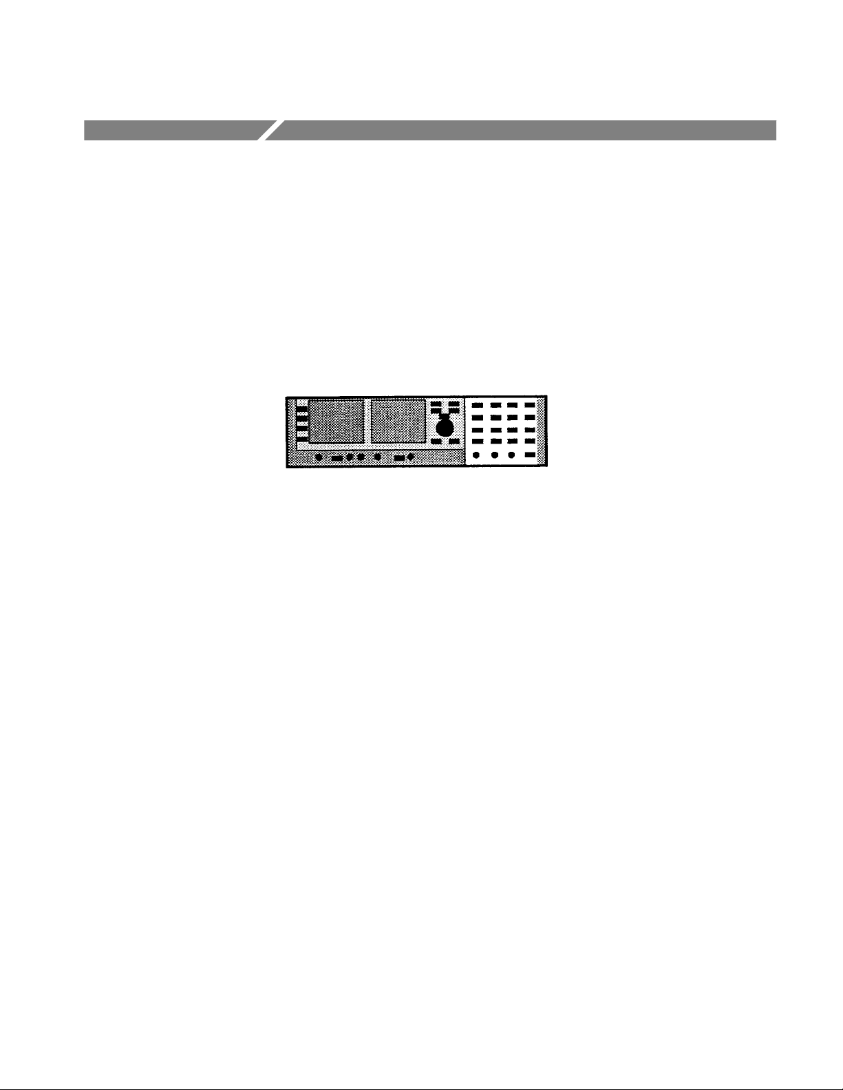
Figure 1–1: Simplified representation of the 1780R-Series
Video Measurement Set 1–1. . . . . . . . . . . . . . . . . . . . . . . . . . . . . . . . . .
Figure 2–1: Rear panel for the Tektronix 1780R-Series
Measurement Set 2–3. . . . . . . . . . . . . . . . . . . . . . . . . . . . . . . . . . . . . . . .
Figure 2–2: Settings for the rear-panel mains selector switch 2–5. . . . . .
Figure 2–3: Upper right portion of the 1780R-Series rear panel,
showing the location of the four loop-through signal inputs 2–8. . . .
Figure 2–4: Remote connector and the function of each pin.
A / before a function indicates a low to activate 2–9. . . . . . . . . . . . . . .
Figure 2–5: Serial interface connector showing the function of
each pin 2–10. . . . . . . . . . . . . . . . . . . . . . . . . . . . . . . . . . . . . . . . . . . . . . .
Figure 2–6: RS232D serial interface adapter diagram 2–11. . . . . . . . . . . .
Figure 2–7: Rear-panel XY connector diagram showing the function
of each pin 2–13. . . . . . . . . . . . . . . . . . . . . . . . . . . . . . . . . . . . . . . . . . . . .
Figure 2–8: Location of the four screws that secure the instrument
to rack mounting cabinet or portable case 2–14. . . . . . . . . . . . . . . . . . .
Figure 2–9: Dimensions used for rack mounting the 1780R-Series
Video Measurement Set 2–15. . . . . . . . . . . . . . . . . . . . . . . . . . . . . . . . . .
Figure 2–10: Dimensions of the adjustable rear rackmounting
bracket 2–15. . . . . . . . . . . . . . . . . . . . . . . . . . . . . . . . . . . . . . . . . . . . . . . .
Figure 2–11: Installing rear rack-mounting brackets for rack
applications of depths from 18 to 24 inches 2–16. . . . . . . . . . . . . . . . . .
Figure 2–12: Portable case for the 1780R-Series Video Measurement
Set. Case has handle, feet, and an elevating bail along with two
panel covers 2–17. . . . . . . . . . . . . . . . . . . . . . . . . . . . . . . . . . . . . . . . . . . .
Figure 2–13: Waveform Calibration menu display 2–20. . . . . . . . . . . . . . .
Figure 2–14: 1780R (NTSC) Vectorscope Calibration menu display
with CAL OSC on 2–23. . . . . . . . . . . . . . . . . . . . . . . . . . . . . . . . . . . . . . .
Figure 2–15: 1781R (PAL) Vectorscope Calibration menu display 2–23. .
Figure 2–16: 1780R-Series repackaging 2–25. . . . . . . . . . . . . . . . . . . . . . . .
Figure 2–17: Simplified representation of the 1780R Series showing
the location of the control groups 2–27. . . . . . . . . . . . . . . . . . . . . . . . . .
Figure 2–18: Front panel of the 1780R-Series Video Measurement
Set 2–28. . . . . . . . . . . . . . . . . . . . . . . . . . . . . . . . . . . . . . . . . . . . . . . . . . . .
Figure 2–19: The right front panel for the Tektronix 1780R-Series,
showing the Functional Measurement Controls 2–31. . . . . . . . . . . . . .
1780R-Series Service Manual
v
Page 12

Table of Contents
Figure 4–1: 5% signal Attenuator for checking differential gain 4–4. . . .
Figure 4–2: Rear view of the X Y plug connections. (Pins 2, 4, 6,
10, 12, and 14 can be used to make ground connections.) 4–5. . . . . . .
Figure 4–3: REMOTE connector modified for Remote Sync input 4–5. .
Figure 4–4: RGB Parade Display Test Connector 4–6. . . . . . . . . . . . . . . .
Figure 4–5: Initial equipment hook-up for the Performance Check
Procedure 4–11. . . . . . . . . . . . . . . . . . . . . . . . . . . . . . . . . . . . . . . . . . . . . .
Figure 4–6: Test equipment connections for checking calibrator
amplitude accuracy 4–13. . . . . . . . . . . . . . . . . . . . . . . . . . . . . . . . . . . . . .
Figure 4–7: Identification of marks and divisions on the graticule
baseline 4–16. . . . . . . . . . . . . . . . . . . . . . . . . . . . . . . . . . . . . . . . . . . . . . . .
Figure 4–8: Test equipment connections for checking CH A
frequency response 4–23. . . . . . . . . . . . . . . . . . . . . . . . . . . . . . . . . . . . . .
Figure 4–9: Connections for checking AUX OUT frequency response.
(Only Ch 1 of the test oscilloscope dual-trace unit is used.) 4–27. . . . .
Figure 4–10: Vector graticule showing the –3 dB points for checking
frequency response 4–55. . . . . . . . . . . . . . . . . . . . . . . . . . . . . . . . . . . . . .
Figure 4–11: Properly adjusted xy input gains 4–61. . . . . . . . . . . . . . . . . . .
Figure 4–12: Connections for checking line strobe pulse timing 4–63. . . .
Figure 4–13: Setting up the Return Loss Bridge: a) setup 500 mV
amplitude; b) Nulling the bridge 4–66. . . . . . . . . . . . . . . . . . . . . . . . . . .
Figure 4–14: Measuring return loss of 1780R-Series CH A INPUT 4–67. .
Figure 5–1: Simplified representation of the 1780R-Series Video
Measurement Set, showing the location of the four control
groups 5–2. . . . . . . . . . . . . . . . . . . . . . . . . . . . . . . . . . . . . . . . . . . . . . . . .
Figure 5–2: Calibrate menu as displayed on the Vectorscope CRT 5–2. .
Figure 5–3: 1780R-Series circuit board assembly locations 5–3. . . . . . . .
Figure 5–4: Rear view of the X Y plug connections. (Pins 2, 4, 6,
10, 12, and 14 can be used to make ground connections.) 5–7. . . . . . .
Figure 5–5: RGB Parade Display Test Connector 5–7. . . . . . . . . . . . . . . .
Figure 5–6: Initial signal connections for re-adjustment of the
1780R-Series 5–13. . . . . . . . . . . . . . . . . . . . . . . . . . . . . . . . . . . . . . . . . . .
Figure 5–7: Adjustment and test point locations on the
Waveform HV Supply circuit board (Assembly 16.) 5–15. . . . . . . . . . .
Figure 5–8: Adjustment locations on the Vectorscope HV Supply
circuit board (Assembly A3) 5–17. . . . . . . . . . . . . . . . . . . . . . . . . . . . . .
Figure 5–9: Adjustment locations on the Microprocessor circuit
board (Assembly A5) 5–18. . . . . . . . . . . . . . . . . . . . . . . . . . . . . . . . . . . .
Figure 5–10: Waveform circuit board (Assembly A2) adjustment,
test point, and jumper locations. 5–19. . . . . . . . . . . . . . . . . . . . . . . . . . .
vi
1780R-Series Service Manual
Page 13

Table of Contents
Figure 5–11: Adjustment locations on the Vectorscope circuit board
(Assembly A6) 5–21. . . . . . . . . . . . . . . . . . . . . . . . . . . . . . . . . . . . . . . . . .
Figure 5–12: Connections for adjusting the calibrator amplitude 5–22. . .
Figure 5–13: Input & BNC circuit board (A8) adjustments, shown as
they would appear with the instrument on its left side 5–25. . . . . . . . .
Figure 5–14: Test equipment connections for matching CH A and
CH B1 input gains. 5–26. . . . . . . . . . . . . . . . . . . . . . . . . . . . . . . . . . . . . .
Figure 5–15: Test equipment connections for adjusting CH A
frequency response 5–31. . . . . . . . . . . . . . . . . . . . . . . . . . . . . . . . . . . . . .
Figure 5–16: Adjustment and test point (TP) locations for the
Oscillator circuit board (Assembly A7). 5–41. . . . . . . . . . . . . . . . . . . . .
Figure 5–17: Noise Reduction–ON. DAC offset properly adjusted 5–47. .
Figure 5–18: Noise Reduction–OFF. Demod offset properly adjusted 5–48
Figure 5–19: Z-Axis circuit board (A4) adjustment and test
point locations 5–51. . . . . . . . . . . . . . . . . . . . . . . . . . . . . . . . . . . . . . . . . .
Figure 5–20: Vector graticule x- and y-axis markings for adjusting
xy input gains 5–53. . . . . . . . . . . . . . . . . . . . . . . . . . . . . . . . . . . . . . . . . .
Figure 5–21: Properly adjusted xy input gains 5–54. . . . . . . . . . . . . . . . . . .
Figure 6–1: Front panel parts 6–6. . . . . . . . . . . . . . . . . . . . . . . . . . . . . . . .
Figure 6–2: Positions of the waveform CRT deflection leads 6–9. . . . . . .
Figure 6–3: Rear panel for the Tektronix 1780R-Series Video
Measurement Set showing the location of sub-assembly
mounting screws 6–10. . . . . . . . . . . . . . . . . . . . . . . . . . . . . . . . . . . . . . . .
Figure 6–4: Using foldout pages 6–15. . . . . . . . . . . . . . . . . . . . . . . . . . . . . . .
Figure 6–5: 1780R-Series circuit board assembly locations 6–18. . . . . . . .
Figure 6–6: Connections for the external power supply leads 6–23. . . . . .
Figure 6–7: Connecting the AC mains to the 1780-R Series for
troubleshooting 6–24. . . . . . . . . . . . . . . . . . . . . . . . . . . . . . . . . . . . . . . . .
Figure 6–8: A. Q250 collector waveform. B. Q250 base waveform.
C. Q350–Q451 emitter waveform. D. U460 pin 3 waveform.
E. U460 pin 4 waveform 6–27. . . . . . . . . . . . . . . . . . . . . . . . . . . . . . . . . .
Figure 6–9: +5 V supply output waveform when over voltage
protection is operating 6–28. . . . . . . . . . . . . . . . . . . . . . . . . . . . . . . . . . .
Figure 6–10: Power supply load used when adjusting current limit
(A1R466). Load can be connected between the top end of
A2L638 and ground 6–28. . . . . . . . . . . . . . . . . . . . . . . . . . . . . . . . . . . . .
1780R-Series Service Manual
vii
Page 14

Table of Contents
List of Tables
Table 1–1: Input/Output 1–4. . . . . . . . . . . . . . . . . . . . . . . . . . . . . . . . . . . .
Table 1–2: Waveform Monitor Vertical System 1–5. . . . . . . . . . . . . . . . .
Table 1–3: Waveform Monitor Probe Input 1–8. . . . . . . . . . . . . . . . . . . .
Table 1–4: Waveform Monitor Horizontal Deflection System 1–8. . . . . .
Table 1–5: Waveform Monitor dG and dP Display 1–11. . . . . . . . . . . . . . .
Table 1–6: Synchronization 1–12. . . . . . . . . . . . . . . . . . . . . . . . . . . . . . . . . .
Table 1–7: Vectorscope Vector Display 1–13. . . . . . . . . . . . . . . . . . . . . . . . .
Table 1–8: Vectorscope X-Y Display 1–15. . . . . . . . . . . . . . . . . . . . . . . . . . .
Table 1–9: Vectorscope SCH Phase Display 1–15. . . . . . . . . . . . . . . . . . . . .
Table 1–10: CRTs and High Voltage Supplies 1–16. . . . . . . . . . . . . . . . . . .
Table 1–11: Power Requirements 1–16. . . . . . . . . . . . . . . . . . . . . . . . . . . . .
Table 1–12: Environmental Summary 1–17. . . . . . . . . . . . . . . . . . . . . . . . .
Table 1–13: Physical Characteristics 1–17. . . . . . . . . . . . . . . . . . . . . . . . . .
Table 1–14: Certifications and Compliances 1–18. . . . . . . . . . . . . . . . . . . .
Table 2–1: 1780R-Series Standard Accessories 2–1. . . . . . . . . . . . . . . . . .
Table 2–2: Partial List of Optional Accessories Available for the
1780R-Series 2–2. . . . . . . . . . . . . . . . . . . . . . . . . . . . . . . . . . . . . . . . . . .
Table 2–3: Plug Jumpers for Waveform Board (Assembly A2)
(Schematic Diagrams 3 through 15) 2–6. . . . . . . . . . . . . . . . . . . . . . . .
Table 2–4: Plug Jumpers and DIP Switch on the Microprocessor
Board (Assembly A5) (Schematic Diagrams 16 through 19) 2–7. . . .
Table 2–5: Plug Jumpers for Vectorscope Board (Assembly A6)
and Oscillator Board (Assembly A7) 2–7. . . . . . . . . . . . . . . . . . . . . . .
Table 2–6: Serial Remote Commands 2–11. . . . . . . . . . . . . . . . . . . . . . . . . .
Table 2–7: Serial Remote Responses 2–12. . . . . . . . . . . . . . . . . . . . . . . . . . .
Table 3–1: Schematics and Circuit Board Assemblies 3–3. . . . . . . . . . . .
Table 3–2: Input Channel Selection Logic 3–18. . . . . . . . . . . . . . . . . . . . . .
Table 3–3: Filter Selection Logic 3–19. . . . . . . . . . . . . . . . . . . . . . . . . . . . . .
Table 3–4: Memory Switch Outputs 3–93. . . . . . . . . . . . . . . . . . . . . . . . . . .
Table 4–1: Recommended Equipment 4–1. . . . . . . . . . . . . . . . . . . . . . . . .
Table 4–2: 1780R-Series Initial Control Settings 4–10. . . . . . . . . . . . . . . . .
Table 4–3: Common Mode Rejection 4–35. . . . . . . . . . . . . . . . . . . . . . . . . .
Table 4–4: Sweep Timing and Linearity 4–42. . . . . . . . . . . . . . . . . . . . . . . .
viii
1780R-Series Service Manual
Page 15

Table of Contents
Table 5–1: Recommended Equipment 5–4. . . . . . . . . . . . . . . . . . . . . . . . .
Table 5–2: 1780R-Series Adjustments for Calibration Procedure 5–8. .
Table 5–3: 1780R-Series Initial Control Settings 5–12. . . . . . . . . . . . . . . . .
Table 5–4: Low Voltage Power Supply Tolerance 5–14. . . . . . . . . . . . . . . .
Table 6–1: Static Susceptibility 6–3. . . . . . . . . . . . . . . . . . . . . . . . . . . . . . .
Table 6–2: Test Selectable Components 6–16. . . . . . . . . . . . . . . . . . . . . . . .
Table 6–3: Circuit Board Assemblies 6–17. . . . . . . . . . . . . . . . . . . . . . . . . .
Table 6–4: Power Supply External Load Resistances 6–25. . . . . . . . . . . . .
1780R-Series Service Manual
ix
Page 16

Table of Contents
x
1780R-Series Service Manual
Page 17

General Safety Summary
Review the following safety precautions to avoid injury and prevent damage to
this product or any products connected to it. To avoid potential hazards, use this
product only as specified.
Only qualified personnel should perform service procedures.
To Avoid Fire or
Personal Injury
Use Proper Power Cord. Use only the power cord specified for this product and
certified for the country of use.
Connect and Disconnect Properly . Do not connect or disconnect probes or test
leads while they are connected to a voltage source.
Ground the Product. This product is grounded through the grounding conductor
of the power cord. To avoid electric shock, the grounding conductor must be
connected to earth ground. Before making connections to the input or output
terminals of the product, ensure that the product is properly grounded.
Observe All Terminal Ratings. To avoid fire or shock hazard, observe all ratings
and markings on the product. Consult the product manual for further ratings
information before making connections to the product.
Do not apply a potential to any terminal, including the common terminal, that
exceeds the maximum rating of that terminal.
Recharge Batteries Properly. Recharge batteries for the recommended charge
cycle only.
Do Not Operate Without Covers. Do not operate this product with covers or panels
removed.
Use Proper Fuse. Use only the fuse type and rating specified for this product.
1780R-Series Service Manual
Avoid Exposed Circuitry. Do not touch exposed connections and components
when power is present.
Wear Eye Protection. Wear eye protection if exposure to high-intensity rays or
laser radiation exists.
Do Not Operate With Suspected Failures. If you suspect there is damage to this
product, have it inspected by qualified service personnel.
Do Not Operate in Wet/Damp Conditions.
Do Not Operate in an Explosive Atmosphere.
Keep Product Surfaces Clean and Dry .
Provide Proper Ventilation. Refer to the manual’s installation instructions for
details on installing the product so it has proper ventilation.
xi
Page 18
General Safety Summary
Symbols and Terms
T erms in this Manual. These terms may appear in this manual:
WARNING. Warning statements identify conditions or practices that could result
in injury or loss of life.
CAUTION. Caution statements identify conditions or practices that could result in
damage to this product or other property.
T erms on the Product. These terms may appear on the product:
DANGER indicates an injury hazard immediately accessible as you read the
marking.
WARNING indicates an injury hazard not immediately accessible as you read the
marking.
CAUTION indicates a hazard to property including the product.
Symbols on the Product. The following symbols may appear on the product:
CAUTION
Refer to Manual
WARNING
High Voltage
Double
Insulated
Protective Ground
(Earth) Terminal
Not suitable for
connection to
the public telecom-
munications network
xii
1780R-Series Service Manual
Page 19

Service Safety Summary
Only qualified personnel should perform service procedures. Read this Service
Safety Summary and the General Safety Summary before performing any service
procedures.
Do Not Service Alone. Do not perform internal service or adjustments of this
product unless another person capable of rendering first aid and resuscitation is
present.
Disconnect Power. To avoid electric shock, disconnect the mains power by means
of the power cord or, if provided, the power switch.
Use Caution When Servicing the CRT. To avoid electric shock or injury, use
extreme caution when handling the CRT. Only qualified personnel familiar with
CRT servicing procedures and precautions should remove or install the CRT.
CRTs retain hazardous voltages for long periods of time after power is turned off.
Before attempting any servicing, discharge the CRT by shorting the anode to
chassis ground. When discharging the CRT, connect the discharge path to ground
and then the anode. Rough handling may cause the CRT to implode. Do not nick
or scratch the glass or subject it to undue pressure when removing or installing it.
When handling the CRT, wear safety goggles and heavy gloves for protection.
Use Care When Servicing With Power On. Dangerous voltages or currents may
exist in this product. Disconnect power, remove battery (if applicable), and
disconnect test leads before removing protective panels, soldering, or replacing
components.
To avoid electric shock, do not touch exposed connections.
X-Radiation. To avoid x-radiation exposure, do not modify or otherwise alter the
high-voltage circuitry or the CRT enclosure. X-ray emissions generated within
this product have been sufficiently shielded.
1780R-Series Service Manual
xiii
Page 20

Service Safety Summary
xiv
1780R-Series Service Manual
Page 21

Preface
This Service Manual is part of a 2-volume set. Its companion manual is the
Operator’s Manual, which is aimed primarily at operating personnel. Information
in this volume is intended for those who are required to maintain the 1780R-Series Video Measurement Set.
Specific instructional procedures can be found in the Performance Check,
Adjustment Procedures, Maintenance and Installation sections. In addition, the
lists of Replaceable and Mechanical Parts along with circuit board component
locating dollies and schematic diagrams are at the back of this manual.
Operating Information is a very simple explanation of the controls and connectors. If there is a question involving one of the specific measurement applications, it may be necessary to consult the Operator’s Manual to determine if there
is an instrument malfunction or simply an operator error.
Special techniques are required to service the 1780R-Series Low Voltage Power
Supply. Consult Troubleshooting before attempting to work on the Low Voltage
Power Supply.
To assist in locating information in this volume there is a complete Table of
Contents, augmented by a List of Illustrations and a List of Tables.
1780R-Series Service Manual
xv
Page 22

Preface
xvi
1780R-Series Service Manual
Page 23

Page 24
Product Description
The Tektronix 1780R-Series Video Measurement Set is a 19-inch wide,
5 1/4-inch high, 18-inch deep dual-CRT Waveform Monitor/Vectorscope. It
weighs approximately 28 pounds and is intended for rack-mount applications,
but can also be configured as a full (rack) width cabinet model for bench and
portable applications. See Figure 1–1. The remainder of the front-panel area
contains controls and switches that manually configure the instrument for
measurements. Both CRTs have alphanumeric readout and touch-screen control
to simplify measurement tasks and operating menus.
Figure 1–1: Simplified representation of the 1780R-Series Video Measurement Set
The left CRT is selectively used for vectorscope, picture monitor, SCH phase,
and XY displays, while the right one is used for the waveform monitor displays.
The picture monitor display has a bright-up strobe; when the instrument is in a
line select mode, that makes its display identical to that of a picture monitor
driven from the rear-panel Pix Mon Out.
1780R-Series Service Manual
The right CRT is used for the normal filtered waveform monitor displays.
Waveform monitor measurements can have voltage and time cursors added to the
display to improve measurement accuracy. The elapsed time or amplitude
difference between cursors is displayed as alphanumeric CRT readout. Besides
the typical waveform monitor displays the right CRT is used for high-resolution,
high-accuracy differential gain and phase measurements.
Signal and reference input is through 75 W bridging loop-through inputs. There
are four composite video inputs, making it possible to use the 1780R-Series to
measure analog component signals, if desired. In addition to the normal 1- or
2-line, and 1- or 2-field displays, both component and composite signals can be
displayed in parade or overlay mode. The external reference can be either
composite sync or black burst. The 1780R-Series can also be operated with an
external subcarrier reference input, similar to the Tektronix 520-Series.
All instruments in the series have a front-panel, high impedance (1 MW) probe
input. Signals input through the probe can be displayed as single or multiple
lines or fields and can also be overlayed or paraded with the rear-panel input
1–1
Page 25

Product Description
signals. The probe input has gain and input compensation for both X1 and X10
probes.
The instrument control system is based on a National Semiconductor 32CG16
Microprocessor, with an additional line rate processor that makes line-by-line
measurement decisions. Front-panel switching and CRT touch-screen selections
are acted upon by the processors. The front-panel switches are momentary
touch-type, which toggle through a short list of functions and provide additional
selections when held in. Each switch has a back-lighted functional indicator or
built-in indicator to relay switch status to the operator. In addition to sensing and
acting on switch and touch panel changes, the Microprocessor controls the
alphanumeric CRT readout for menu selections and measurement results.
The current front-panel configuration (switch and touch screen) is always stored
in non-volatile memory allowing the instrument to power back up in its previous
measurement configuration. In addition, front-panel configurations can be stored
and recalled (one-button measurement), like the Tektronix 1730-Series.
The use of touch screens and an assignable, multi-function control greatly
simplifies the operator interface. The control is an optical encoder that is used for
line selection, voltage measurements, timing measurements, and subcarrier phase
measurements, along with other menu/touch screen assigned tasks. A pair of
push buttons, adjacent to the control, can be used to duplicate the function of the
control when individual steps are desired.
CRT Options
Power Cord Options
The waveform monitor has reduced spot size and provides a bright display for
showing an individual line. The left CRT provides the vectorscope, picture
monitor, SCH phase and XY displays. Both CRTs have internal measurement
graticules, and can accommodate external graticules that are used for specialized
measurements and some photographic applications. Variable graticule scale
illumination provides uniform lighting over the usable area for both the internal
and external graticules.
Option 74 provides a P4 (white) phosphor tube.
Any of the power cord options described in Maintenance can be ordered for the
1780R-Series. If no power cord option is ordered, instruments are shipped with a
North American 125 V power cord and one replacement fuse.
1–2
1780R-Series Service Manual
Page 26

Specifications
This section of the manual contains the specifications for the 1780R-Series.
Tabular information is divided into two categories. First there are the Performance Requirements which is assured by Tektronix Inc. Second are the items in
the Supplemental Information column, which due to a number of reasons may be
only typical numbers or could vary slightly from one instrument to the next.
The Performance Verification is provided to verify listed Performance Require-
ments. If a step for a specific requirement is not included in this procedure, it is
because the performance has been built into the instrument and is therefore
assured by either the fact that the instrument is operational or is proven correct
by other performance check steps. In a few instances, the procedure to verify a
specification can be extremely difficult or require extremely expensive equipment to verify, which might also cause them to be omitted from the procedure. In
these cases the factory has a procedure, that can be provided if necessary.
The step numbers, that can be used to verify the Performance Requirements and
some critical Supplemental items, are in a column following the Supplemental
Information.
Performance Qualification
The Performance Requirements listed in the Electrical Specification apply over
an ambient temperature range of 0_ C to +50_ C. The rated accuracies are valid
when the instrument is calibrated at an ambient temperature range of +20_ C to
+30_ C, after a warm-up time of 20 minutes. Test equipment used to verify
Performance Requirements must be calibrated and working within the limits
specified under the Equipment Required list.
Heat Dissipation
Maximum heat dissipation is 120 Watts (410 BTU/ Hour).
1780R-Series Service Manual
1–3
Page 27
Specifications
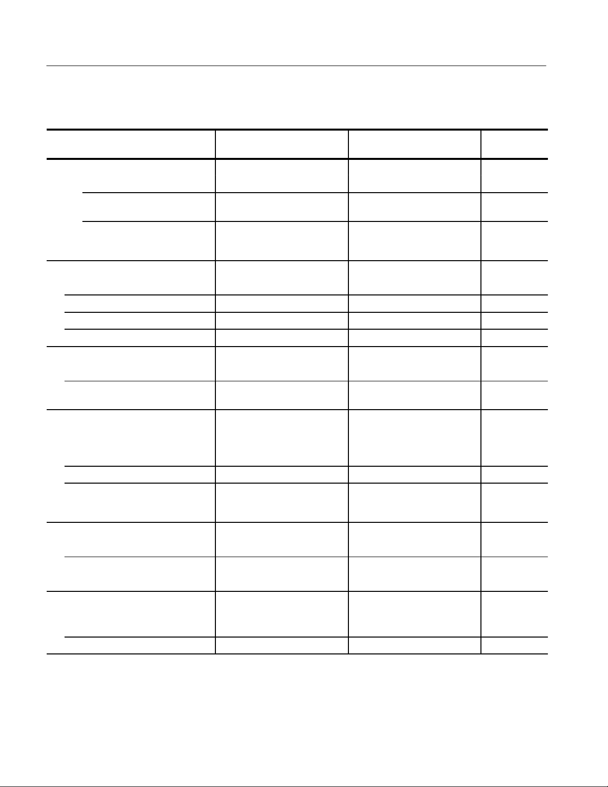
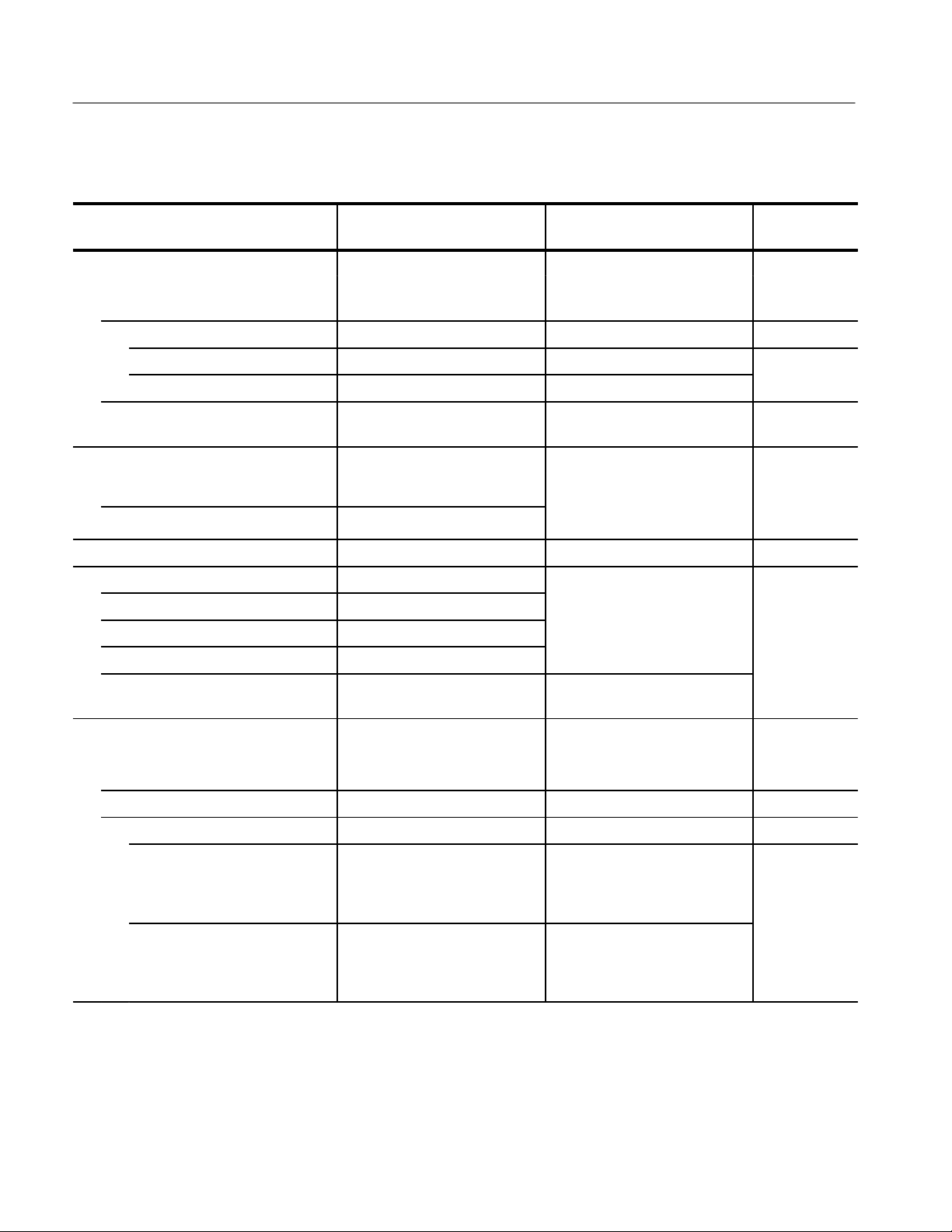
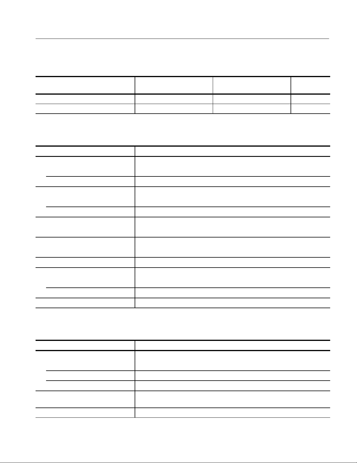
T able 1–1: Input/Output
Characteristic Performance Requirement Supplemental Information
Vertical Ranges
Volts Full Scale Accuracy
Performance
Check Step
1.0 1.0 V ±0.007 V. Peak-to-peak Amplitude for Full
Graticule 1.0 volt/140 IRE.
Var ≤0.5:1 to ≥1.5:1 (0.67 V to 2.0 V
input signal can be made full
scale).
Input Gain Ratios
A to B 1 to 1 ±0.002 (0.998 – 1.002). 10
Auxiliary Video Input to A Input 1.5 dB ±0.3 dB. 10
Input A to Auxiliary Video Output 1 to 1 ±0.005 (0.995 – 1.005). 10
Input A to Picture Monitor Output 1 to 1 ±0.02 (0.98 – 1.02). 10
Vertical Magnifier
X5 Accuracy 0.2 V ±0.007 V .
Peak-to-peak Amplitude for Full
Graticule
Maximum Input Signal
AC Coupled All Inputs 2.0 V , peak-to-peak, 10%–90%
APL.
DC Coupled All Inputs ±1.5 V (DC + peak AC).
0.2 V/28 IRE.
Aux Video Out and Pix Mon
(terminated), 1.0 V peak-to-peak,
10%–90% APL.
4
5
Max volts from Loop-Thru common
terminal to chassis
Max DC Output Voltage
Aux Video Out ±0.5 V into 75 W.
Pix Mon Out ±0.5 V into 75 W.
Remote Control
Interface Standard RS422, RS232 (subset of all
Control Enable Ground closures and presets.
2 V
at mains frequency. Rejection ratio of common-to-
RMS
chassis in floating ground mode,
≥34 dB at mains frequency.
Line strobe but no input signal.
controls).
1–4
7
1780R-Series Service Manual
Page 28
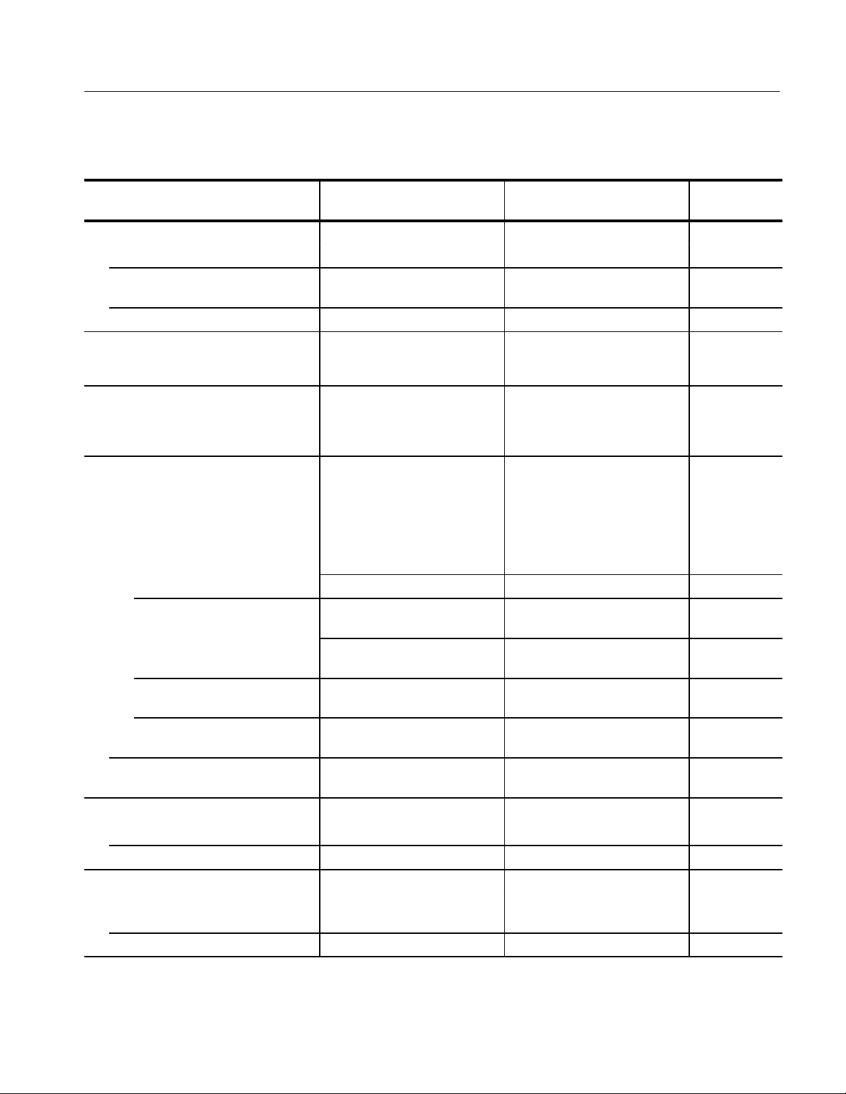
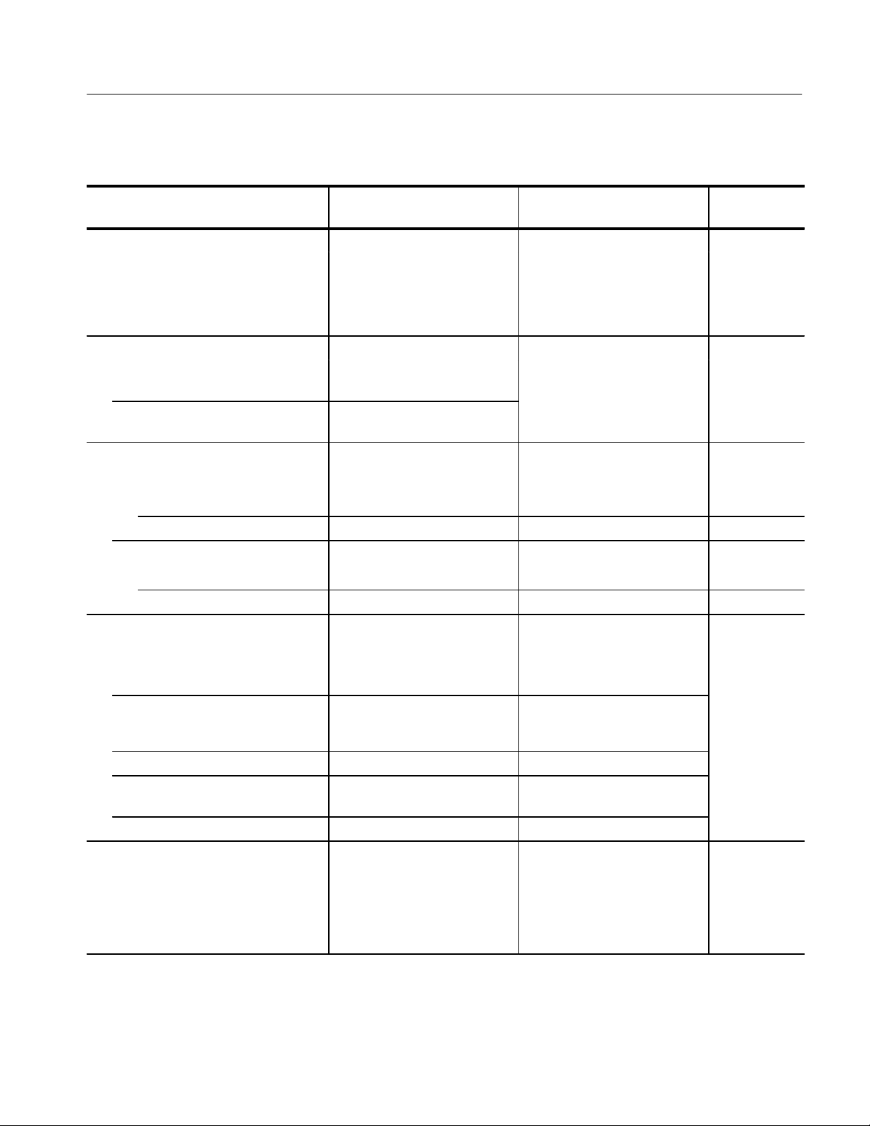
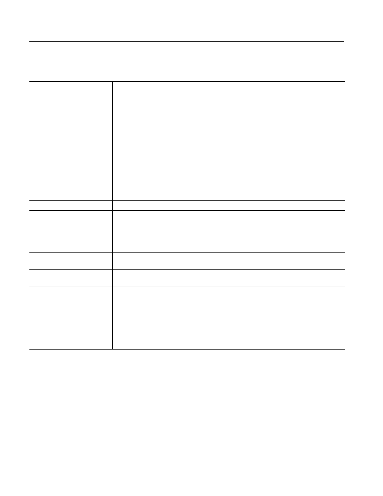
T able 1–2: Waveform Monitor Vertical System
Characteristic Performance Requirement Supplemental Information
Return Loss
CH A, B1, B2, or B3 >40 dB DC to 5 MHz. (Terminated in 75 W.) 58
Specifications
Performance
Check Step
Aux Video In, Aux Video Out, & Pix
Mon Out
Ext. Sync Input >46 dB to 5 MHz. 58
Loop-Through Isolation >80 dB at FSC, between channels
Crosstalk Typically 70 dB isolation between
Frequency Response
Flat (X1)
50 kHz – 5 MHz ±1%. All inputs, 1 V Full Scale, Var.
5 MHz – 10 MHz ±1%. CH A, 1 V Full Scale, Var. Gain
>34 dB DC to 5 MHz. Instrument On only. 58
and each channel and EXT REF.
Measured externally.
channels. Measured at F
between channels and each
channel and EXT REF .
Gain off. Adjusted for min. lum/
chroma gain error. T ypically
<0.5%.
±2%. Aux In, and Aux Out. 15–16
off.
±2%. Ch B1, Ch B2, Ch B3, Aux In, and
Aux Out.
SC
11–15
11
12–16
10 MHz – 15 MHz +2% –5%. All Inputs, 1 V Full Scale, Var.
Gain off.
15 MHz – 20 MHz +2% –15%. All Inputs, 1 V Full Scale, Var.
Gain off. –3 dB at >20 MHz.
Lum/Chroma Gain ±0.5%. X5 Gain with Modulated Sin
Pulse (12.5T NTSC, 10T PAL).
Voltage Cursor
Accuracy ±0.2%. 6
Resolution 1 mV .
Cal Amplitude
Accuracy 1.00 V ±0.2%. NTSC = 0.714 V ±0.5%.
PAL = 0.700 V ±0.5%.
Resolution 1 mV at 1.00 V.
1780R-Series Service Manual
11–15
11–15
2
19
3
1–5
Page 29
Specifications
Adjusted
e
1
error
1
de
s
.
0
T able 1–2: Waveform Monitor Vertical System (Cont.)
Characteristic
DC Restorer
Performance
Supplemental InformationPerformance Requirement
Check Step
Clamp Point Backporch or Sync Tip.
(All clamps controlled together.)
Mains Hum Atten.
Slow Clamp ≤0.9 dB. Attenuation ≤10%.
Fast Clamp ≥26 dB.
Shift caused by presence or absence
of burst
Lum/Chroma Gain Ratio
NTSC (50 kHz – 3.58 MHz) 1:1 ±1%.
PAL (50 kHz – 4.43 MHz) 1:1 ±1%.
DC Channel Matching Typically within 30 mV. 8
Common Mode Rejection AB1 B1B2 / B1B3
60 Hz ≥46 dB ≥46 dB
15 kHz (Lum) ≥46 dB ≥46 dB
1 MHz ≥40 dB ≥34 dB
3.58 or 4.43 MHz (Chroma) ≥34 dB ≥34 dB A – B1 typically >46 dB to
Filters
NTSC = 1 IRE.
PAL = ≤7 mV.
to minimize luminanc
to chrominance gain
Full Scale, typically ≤0.5%.
V peak-to-peak common mo
ignal
6.0 MHz and >40 dB to 10.0 MHz.
at 1 V
21
22
24
9
26
Luminance <3 dB down at 1 MHz. ≥40 dB
down at 3.58 or 4.43 MHz.
Low Pass ≥14 dB down at 500 kHz. Typically –3 dB at 300 kHz.
Chrominance
3.58 MHz ±1% of flat at 3.58 MHz.
3 dB points:
Lower: 2.83 ±0.15 MHz.
Upper: 4.33 ±0.15 MHz.
4.43 MHz ±1% of flat at 4.43 MHz.
3 dB points:
Lower: 3.68 ±0.15 MHz.
Upper: 5.18 ±0.15 MHz.
1–6
2
1780R-Series Service Manual
Page 30
T able 1–2: Waveform Monitor Vertical System (Cont.)
Re
Characteristic
Diff Steps
Specifications
Performance
Supplemental InformationPerformance Requirement
Check Step
(Differentiated Steps Attenuation) >40 dB at 3.58 MHz
(4.43 MHz PAL).
Noise Measurements
Accuracy To 56 dB within 1 dB; 60 dB
within 2 dB.
Offset Accuracy To 56 dB within 0.5 dB; 60 dB
within 1 dB.
Non-Linear Waveform Distortion
Differential Gain
Aux Video Out ≤0.25%, 10% – 90% APL. W aveform modes.
Pix Mon Out ≤0.25%, 10% – 90% APL.
Differential Phase
Aux Video Out ≤0.25°, 10% – 90% APL.
Pix Mon Out ≤0.25°, 10% – 90% APL.
Linear Waveform Distortion
Pulse Overshoot & Ringing ≤1% of applied pulse amplitude. Typically
Pulse and Bar ≤1% of applied pulse amplitude. Typically
25 ms Bar Tilt ≤1% of applied bar amplitude.
5 step, 20 IRE staircase within
2% of flat display.
Vertical Gain increase approx. 5X
to compare staircase risers.
lative to 700 mV
set to maximum.
<0.5% on T Pulse, and
<1.0% on T/2 Pulse.
<0.5% on T Pulse, and
<1.0% on T/2 Pulse.
RMS
, Var Gain
27
9
29
Field Square Wave Tilt ≤1% of applied square wave
amplitude.
2T Sin2 Pulse-to-Bar Ratio 1:1 ±1%.
Vertical Overscan
Baseline Distortion <7 mV variation in baseline of
chroma when positioned anywhere between sync tip and
100% white.
1780R-Series Service Manual
Typically <0.5%.
1 V p-p PAL or NTSC Modulated
2
composite video signal
Sin
(12.5T NTSC, 10T PAL). X1 or
X5, Variable Gain of f. Typically
<0.5%.
23
1–7
Page 31

Specifications
1
T able 1–3: Waveform Monitor Probe Input
Characteristic Performance Requirement Supplemental Information
Input Resistance 1 MW.
Input RC Product 20 ms (20 pF).
Performance
Check Step
Gain Unity ±3%. With gain adjusted for equivalent
1 V peak-to-peak display.
Frequency Response
25 Hz to 10 MHz
Tilt Less than 5% on 50 Hz square
Probe Calibrator
Waveform
Period
Output Voltage
Impedance Out
±3%. Referenced to 50 kHz. 17, 18
Fast DC Restorer eliminates low
wave.
1.0 V ±0.5%. 0.995 to 1.005 V.
frequency tilt on a comp video
signal.
50% Duty Cycle square wave.
4 horizontal lines.
≈950 W.
T able 1–4: Waveform Monitor Horizontal Deflection System
Characteristic Performance Requirement Supplemental Information
Sweep Rates & Timing Accuracy 1 MW.
30
32
3
Performance
Check Step
1 Line (5 ms/Div.) ±2%. Center 10 divisions.
2 Line (10 ms/Div.) ±2%. Center 10 divisions.
3 Line (15 ms/Div.) ±2%. Center 10 divisions.
1-Field Sweep Displays 1 full field including field
rate sync.
2-Field Sweep Displays 2 full fields, and the field
rate sync between them. First
sweep is selectable between the
even or odd field.
3-Field Sweep Displays 3 full fields, and the
2-field rate sync intervals between
them (3/4 of the color frame). First
sweep is selectable between the
even or odd field, third field
polarity is the same as the first
field’s.
1–8
1780R-Series Service Manual
34
Page 32

T able 1–4: Waveform Monitor Horizontal Deflection System (Cont.)
A
des
-
-
A
des
-
-
Waveform m
r-
s
ffere
es.
Characteristic
Sweep Linearity
Specifications
Performance
Supplemental InformationPerformance Requirement
Check Step
1 Line (5 ms/Div.) ±1%.
2 Line (10 ms/Div.) ±1%.
3 Line (15 ms/Div.) ±1%.
1-Field Sweep ±0.5 division.
2-Field Sweep ±0.5 division.
3-Field Sweep ±0.5 division.
Slow Sweep ±5% of full screen over the length
of the sweep.
Magnified Sweep Accuracy
X5 (1 ms/Div.) ±1%.
X10 (0.5 ms/Div.) ±2%.
X20 (0.25 ms/Div.) ±3%.
X25 (0.2 ms/Div.) ±3%.
X50 (0.1 ms/Div.) ±3%.
X100 (50 ns/Div.) ±5%.
Magnified Sweep Linearity
X5 (1 ms/Div.) ±1 minor division (2%).
X10 (0.5 ms/Div.) ±1 minor division (2%).
X20 (0.25 ms/Div.) ±1 minor division (2%).
pplies to the center 10 divisions34
of unmagnified sweep. Exclu
the first 2 divisions of the magni
the first 2 divisions of the magni
fied display.
pplies to the center 10 divisions34
of unmagnified sweep. Exclu
the first 2 divisions of the magni
the first 2 divisions of the magni
fied display.
34
X25 (0.2 ms/Div.) ±1 minor division (2%).
X50 (0.1 ms/Div.) ±1 minor division (2%).
X100 (50 ns/Div.) ±1 minor division (2%).
Variable Sweep Range >±20%. Expands sweep around center of
sweep.
Slow Sweep Duration 4 to 12 seconds. Front panel
variable control.
Timing Cursor Accuracy Within 5 ns, any delay within 1
line (64 ms).
Line Select
Range Full Field.
Field Selection 1 of 4 for NTSC or 1 of 8 for PAL.
Even or Odd and All Fields.
cope may select di
CRT alphanumeric identification.
onitor and vecto
nt lin
1780R-Series Service Manual
35
45
33
36
1–9
Page 33

Specifications
T able 1–4: Waveform Monitor Horizontal Deflection System (Cont.)
Characteristic
RGB/YRGB
Performance
Supplemental InformationPerformance Requirement
Check Step
Staircase Input Amplitude A +10 V input will result in a
horizontal display of 9 divisions
±1.4 major divisions.
Staircase Operating Signal DC Signal levels plus peak AC,
not to exceed _–12 to +12 V .
Max AC Signal Volts 12 V peak-to-peak. Field or line rate sweeps.
Sweep Length
RGB 2 Fld = 27 – 33% of normal.
YRGB 2 Fld = 20 25% of normal.
Sweep Repetition Rate Field or line rate of displayed
video or external sync signal as
selected by front-panel HORI-
ZONT AL controls.
External Horiz. Input Used for ICPM measurements.
Sensitivity Direct coupled 0 – 5 V. Sawtooth
Input Impedance ≈10 kW.
Ground to +10 V . +10 V corresponds to left side of CRT.
1 Line = 27 – 33% of normal.
2 Line = 27 – 33% of normal.
1 Line = 20 – 25% of normal.
2 Line = 20 – 25% of normal.
Requires 1H or 1Fld sweep
selection.
input of up to 5 V is nominally a
10 division horizontal sweep.
37
38
1–10
1780R-Series Service Manual
Page 34

T able 1–5: Waveform Monitor dG and dP Display
CRT read
.
CRT read
.
0
1
Characteristic Performance Requirement Supplemental Information
Differential Gain
Specifications
Performance
Check Step
Deflection Factor 5% dG deflects the trace 50 IRE
(NTSC) or 500 mV (PAL) ±5%.
Residual dG (10 – 90% APL) ≤0.2%, last 90% of trace. 39
Calibrated dG
Resolution 0.1%.
Accuracy 0.1% ±10% of reading.
Range ±5%.
Differential Phase
Deflection Factor 5_ dP deflects the trace 50 IRE
(NTSC) or 500 mV (PAL) ±5%.
Residual dP (10 – 90% APL) ≤0.1_, last 90% of trace. 40
Calibrated dP
Resolution 0.05_.
Accuracy ±0.1_ over any 10_ increment.
±0.1_ over full 360_, Ext. Ref.
±0.2_ burst lock.
Range 360_.
Waveform gain X1, Var. Gain off.
Vector gain adjusted to place
chroma at compass rose.
out
Waveform gain X1, Var. Gain off.
Vector gain adjusted to place
chroma at compass rose.
out
39
39
40
4
Recursive Filter
Noise Reduction ≈15 dB signal-to-noise reduction
with filter selected. Assumes
white noise source.
Cross-Luminance Rejection ≈30 dB with filter selected. 0 dB
in dual dP/dG mode.
Unit Sample Response Settles to within 1 dB in <50 lines
with a step in APL. Settles to
within 1 dB in <50 frames in line
select.
Chrominance Bandwidth 500 kHz ±100 kHz baseband.
1780R-Series Service Manual
4
1–11
Page 35

Specifications
T able 1–6: Synchronization
Characteristic Performance Requirement Supplemental Information
Sync Input
Internal
Performance
Check Step
Ref. Sync Separator 0.2 to 2.0 V peak-to-peak com-
posite video.
Int. Sync Separator 0.5 to 2.0 V peak-to-peak com-
posite video.
External
Black Burst –14 dB to +6 dB. Black Burst signal of 0.2 to 5
Composite Sync 0.2 to 8.0 V peak-to-peak. Composite sync applied to EXT
SCH Modes 286 mV (300 mV PAL) Sync and
Burst ±3 dB.
Direct Sync
Horiz. Freq. Range 15.75 kHz ±1 kHz. Frequencies much below
Sync Jitter
Comp sync or video ≤12 ns with respect to input sync. 44
Variable APL (10–90%) ≤20 ns; with the addition of 36 dB
Composite video applied to Inputs
A, B1, B2, or B3 or probe.
times amplitude applied to EXT
SYNC input.
SYNC input locks waveform
monitor; vectorscope also requires CW signal.
Composite Video or Black Burst. 56
15.75 kHz will not permit a normal
TV display.
white noise ≤90 ns.
42
42
43
43
Noise Immunity <250 ns jitter , 1 V composite
video with _–26 dB white noise.
AFC Sync
Horiz. Freq. Range 15.75 kHz ±200 Hz.
Lock-In Time <1 second.
Sync Jitter
Comp sync or video
Variable APL (10–90%)
Jitter with respect to white noise ≤30 ns. Doubles with each 6 dB increase
Noise Immunity <90 ns jitter , 1 V composite video
1–12
≤10 ns; with the addition of 36 dB
white noise ≤12 ns.
in white noise.
with _–26 dB white noise.
1780R-Series Service Manual
44
Page 36
T able 1–6: Synchronization (Cont.)
NTSC
.
Characteristic
Jitter from missing line sync pulses <15 ns per missing sync pulse.
Slow Sweep Triggering
Supplemental InformationPerformance Requirement
Maximum of 10 consecutive line
sync pulses.
Specifications
Performance
Check Step
Signal APL change from 10% to ≤90%. Front panel selectable for either +
or _– level change.
Sensitivity 0.4 V to 2.0 V peak-to-peak
composite video with APL
change.
Rate 0.2 Hz. Free runs at rates less than
0.2 Hz or with no triggering signal.
Remote Sync
Amplitude 2.0 to 5.0 V square wave, or 4.0 V
composite sync.
Input Impedance 1 MW.
Frequency 30/60 Hz (NTSC), 25/50 Hz (PAL)
Input enabled through rear-panel
REMOTE connector.
square wave will synchronize a
2-field sweep. Remote sync
bypasses the sync stripper and
field ID circuits.
T able 1–7: Vectorscope Vector Display
Characteristic Performance Requirement Supplemental Information
Phase Control
45
46
Performance
Check Step
Digital Phase Shifter
Phase Accuracy ±0.1_. (External CW signal.) 0.25_ Burst
Lock.
Resolution 0.05_.
Chrominance Bandwidth
Upper –3 dB Point FSC +500 kHz, ±100 kHz.
Lower –3 dB Point FSC _–500 kHz, ±100 kHz.
Chrominance Transient Response Modulated Sin2 pulse in R-Y
FSC (Subcarrier Frequency)
– 3.579545 MHz
PAL – 4.43361875 MHz.
mode.
1780R-Series Service Manual
47
48
1–13
Page 37

Specifications
0
10
1
T able 1–7: Vectorscope Vector Display (Cont.)
Characteristic
Display
Performance
Supplemental InformationPerformance Requirement
Check Step
Vector Phase Accuracy ±1.25_. Measured with color bar signal.
Vector Gain Accuracy ±2.5% (1.25 IRE).
Quadrature Phasing ±0.5_.
Subcarrier Regenerator
Pull-In Range
(NTSC) ±50 Hz of FSC.
(PAL) ±10 Hz of FSC.
Pull-In Time Within 1 second, with subcarrier
Phase Shift with Subcarrier Frequency
Change
(NTSC) ±0.5_ from FSC to (FSC +50 Hz),
(PAL) ±0.5_ from FSC to (FSC + 10 Hz),
Phase Shift with Burst Amplitude
Change
Phase Shift with Input Channel
Change
Phase Control Range 360_ continuous rotation. 50
±2_ from nominal burst amplitude
to ±3 dB.
±2_. CH A to CH B1 or CH B1, CH B2,
PAL instruments are tested to
Hz, but typically lock to within
50 Hz.
frequency within 50 Hz (10 Hz for
PAL instruments) of FSC.
or FSC to (FSC –50 Hz).
or FSC to (FSC –10 Hz).
Internal or External burst refer-
ence.
and CH B3 to each other. With
EXT REF selected.
49
5
50
50
Vector Display
Differential Phase ≤1.
Differential Gain ≤1%.
Measured with 140 IRE (1 V)
linearity signal with 40 IRE
(300 mV) of subcarrier.
Position Control Range
Horizontal ≥1/4 inch (6 mm) from center.
Vertical ≥1/4 inch (6 mm) from center .
Clamp Stability 1/64 inch (0.4 mm) or less. Center Spot movement with
rotation of PHASE control.
1–14
1780R-Series Service Manual
5
51
Page 38

T able 1–7: Vectorscope Vector Display (Cont.)
Characteristic
Variable GAIN Range +14 dB to –6 dB of 75% color bar
preset gain.
Max Gain >X5.
Supplemental InformationPerformance Requirement
Unterminated color bar signal can
be brought to appropriate targets.
Burst from a triple terminated
signal can be moved to the
compass rose.
Specifications
Performance
Check Step
52
Variable GAIN Phase Shift ±1_ as gain is varied from +3 dB
to – 6 dB.
T able 1–8: Vectorscope X-Y Display
Characteristic Performance Requirement Supplemental Information
Input DC coupled differential inputs
through rear-panel connector.
Input Amplitude 2 to 9 V peak-to-peak. Adjustable full scale deflection
0 dBm to +12 dBm for 600 W
system. Factory set to 0 dBm.
Maximum Input Voltage ±15 V combined peak signal and
DC.
Frequency Response DC to >500 kHz. 3 dB point. 55
X and Y Input Phase Matching < a trace width of separation at
20 kHz.
Single-ended. Phase matching
above 20 kHz may be improved
by adjusting Vertical Deflection
Amplifier VHF Compensation.
53
Performance
Check Step
54
T able 1–9: Vectorscope SCH Phase Display
Characteristic Performance Requirement Supplemental Information
Accuracy
Absolute ±5_ phase at 25_ C.
Relative ±2_.
Acquisition Time ≤1 sec. 56
Display Phase Error caused by CRT
Geometry Variations
±1.25_ calibrated for zero display
phase error at zero SCH phase.
1780R-Series Service Manual
Performance
Check Step
56
1–15
Page 39
Specifications
.
T able 1–9: Vectorscope SCH Phase Display (Cont.)
Characteristic
Input Timing Correct relative SCH operation
Display Range
Ext Reference 360_.
Int Reference ±70_. Typically >80_. 56
Supplemental InformationPerformance Requirement
with displayed video delayed up
to 2 ms or advanced up to 1.5 ms
relative to external reference.
T able 1–10: CRTs and High Voltage Supplies
Performance
Check Step
Characteristic Performance Requirement Supplemental Information
Waveform Monitor
Viewing Area 80 × 100 mm. Horizontal Scale
12.5 Divisions. Vertical Scale 170
IRE (NTSC), 1.19 V (PAL).
Accelerating Potential Nominally 20 kV .
Orthogonality ±1_. 57
Trace Rotation Range ≥±1_ from horizontal. Typical adjustment range is ≈8_. 57
Vectorscope
Viewing Area 80 × 100 mm.
Accelerating Potential Nominally 13.75 kV .
Orthogonality ±1_. 57
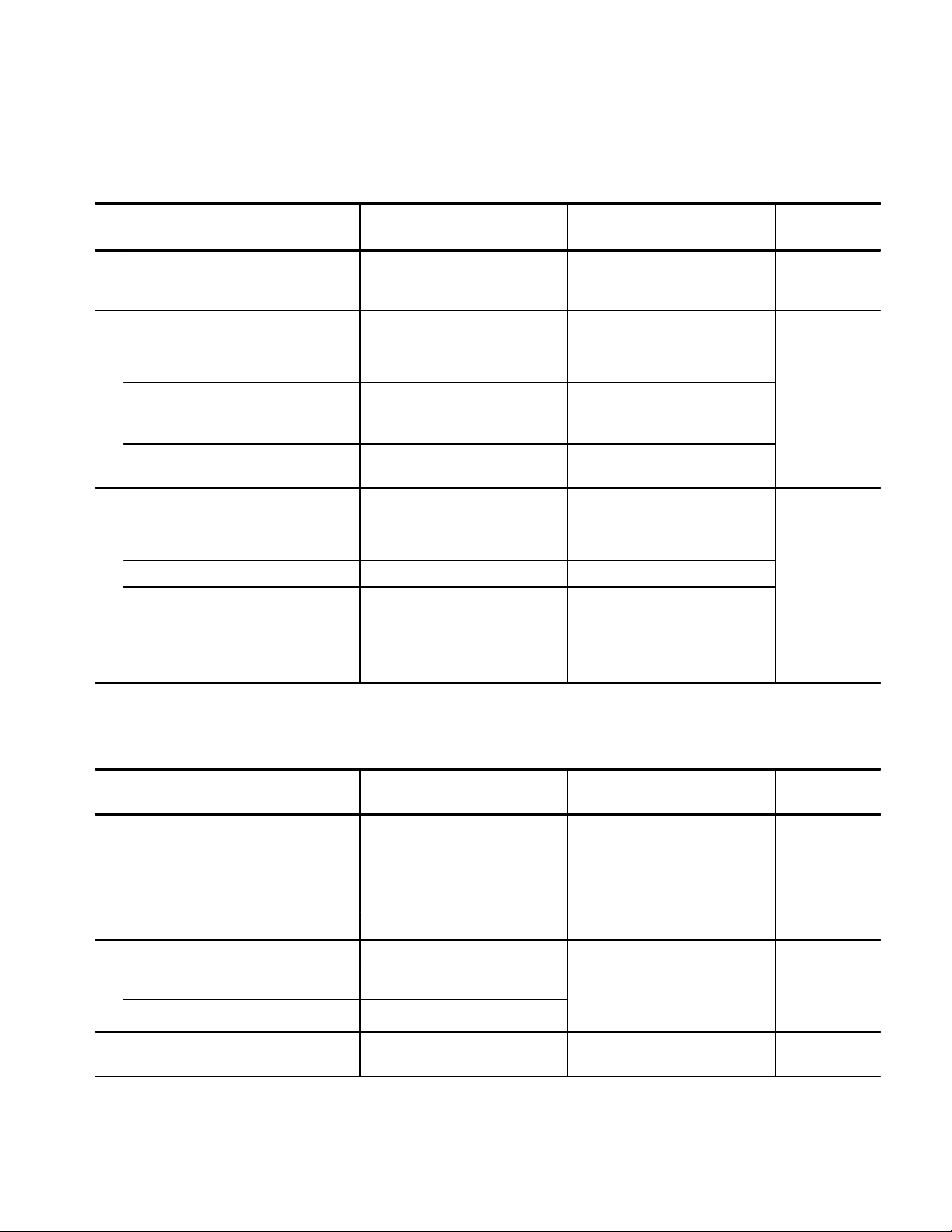
T able 1–11: Power Requirements
Characteristic Performance Requirement Supplemental Information
Mains Voltage Ranges
Performance
Check Step
Performance
Check Step
110 VAC 90 – 132 V .
220 VAC 200 – 250 V .
Mains Frequency Range 48 – 66 Hz.
1–16
Selected by rear-panel switch
1780R-Series Service Manual
1
Page 40
T able 1–11: Power Requirements (Cont.)
Characteristic
Crest Factor ≥1.3.
Power Consumption 120 Watts maximum.
Supplemental InformationPerformance Requirement
T able 1–12: Environmental Summary
Characteristic Performance Requirement
Temperature
Operating 0_ C to +50_ C.
Non-Operating 55_ C to +75_ C.
Altitude
Operating To 15,000 feet (4.5 km) maximum.
Specifications
Performance
Check Step
Non-Operating To 50,000 feet (15 km) maximum.
Vibration
Operating 0.015 inch (0.38 mm) peak-to-peak 10–55 Hz, 75 minutes total.
Shock
Non-Operating 30 g acceleration 3 times each major axis. 11 ms halfsine.
Bench Handling 4 inch drop to table top on each of the four bottom corners.
Transportation
Vibration Qualified under National Safe Transit Association (NST A) Test Procedure 1A-B-1.
Drop Test Qualified under NSTA Test Procedure 1A-B-2.
Humidity 90 to 95% Noncondensing
T able 1–13: Physical Characteristics
Characteristic Supplemental Information
Dimensions
Height 5 1/4 inches (133.4 mm).
Width 19 inches (483 mm).
Length 18 inches (460 mm).
Net Weight Approximately 28 lbs (approximately 12.7 kg). Add 7 lbs (3.2 kg) for accessories and
manuals.
Shipping Weight Approximately 45 lbs (approximately 20.3 kg).
1780R-Series Service Manual
1–17
Page 41
Specifications
T able 1–14: Certifications and Compliances
EC Declaration of Conformity –
EMC
FCC Compliance Emissions comply with FCC Code of Federal Regulations 47, Part 15, Subpart B, Class A Limits
EC Declaration of Conformity –
Low Voltage
U.S. Nationally
Recognized Laboratory Listing
Canadian Certification CAN/CSA C22.2 No. 231 CSA Safety Requirements for Electrical and Electronic Measuring and
Installation Category Descriptions Terminals on this product may have different installation category designations. The installation
Meets intent of Directive 89/336/EEC for Electromagnetic Compatibility. Compliance was
demonstrated to the following specifications as listed in the Official Journal of the European
Communities:
EN 50081-1 Emissions:
EN 55022 Class B Radiated and Conducted Emissions
EN 50082-1 Immunity:
IEC 801-2 Electrostatic Discharge Immunity
IEC 801-3 RF Electromagnetic Field Immunity
IEC 801-4 Electrical Fast Transient/Burst Immunity
High-quality shielded cables must be used to ensure compliance to the above listed
standards.This product complies when installed into any of the following Tektronix
instrument enclosures:
1700F00 Standard Cabinet
1700F02 Portable Cabinet
1700F05 Rack Adapter
Compliance was demonstrated to the following specification as listed in the Official Journal of the
European Communities:
Low Voltage Directive 73/23/EEC
HD401 S1 Safety requirements for electronic measuring apparatus
UL1244 Standard for Electrical and Electronic Measuring and Testing Equipment.
T est Equipment.
categories are:
CA T III Distribution-level mains (usually permanently connected). Equipment at this level is
typically in a fixed industrial location
CA T II Local-level mains (wall sockets). Equipment at this level includes appliances, portable
tools, and similar products. Equipment is usually cord-connected
CA T I Secondary (signal level) or battery operated circuits of electronic equipment
1–18
1780R-Series Service Manual
Page 42

Page 43

Installation
Assembly
Overview
This section provides information on both mechanical and electrical installation
of the 1780R-Series Video Measurement Set. Be sure to read this material prior
to physically mounting the instrument in either a rack mount or portable
configuration.
Packaging
Accessories
The shipping carton and pads provide protection for the instrument during
transit, and should be retained in case subsequent shipment becomes necessary.
Repackaging instructions, including an illustration, can be found at the end of
this section.
The 1780R-Series comes with a set of standard accessories, which includes items
such as manuals, rack-mounting hardware, external graticules, power cord, spare
fuse, etc. Table 2–1 is a list of these standard accessories. Not all of the items in
the table (especially power cables and graticules) are appropriate for all
instruments. Part numbers for these accessories are located at the back of the
manual in the Replaceable Mechanical Parts List.
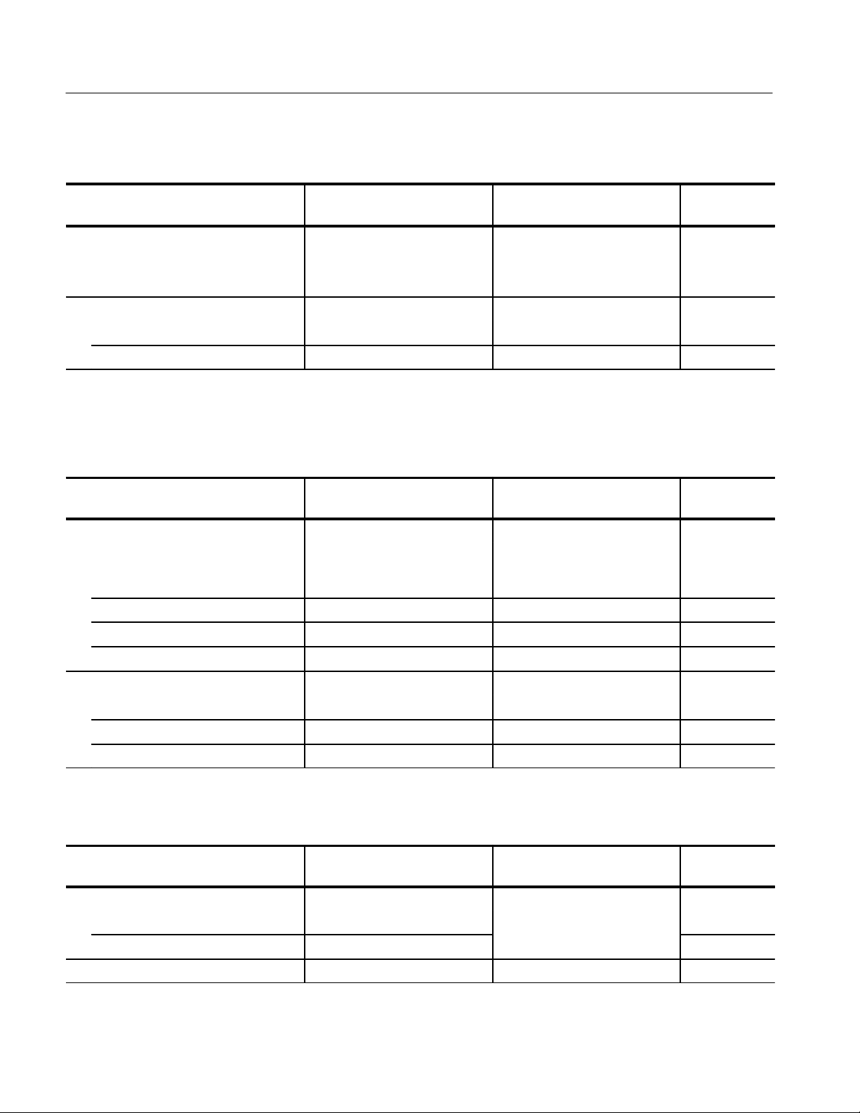
T able 2–1: 1780R-Series Standard Accessories
Item Description
1 Manual 1 – Operator Manual
3 External Graticules per Standard 1– IEEE STD 511 Visual (1780)
1– IEEE STD. 511 Photo (1780)
1– PAL K-Factor V isual (1781)
1– PAL K-Factor Photo (1781)
1780R-Series Service Manual
Power Cable
(1 of 5 options)
1 Spare Fuse 250 V 2A T-type Cartridge fuse
3 Incandescent Bulbs Spare Graticule Lights
1 Air Filter For rear-panel fan
2 Mounting Brackets For rear rack-mounting
Option Country of Use
––– North Amer. (115 V)
A1 European (220 V)
A2 U K (240 V)
A3 Australian (240 V)
2–1
Page 44

Installation
In addition to the standard accessories in Table 2–1 there are a number of
optional accessories that can be purchased, such as a portable case, maintenance
kits, etc., to complement the 1780R-Series Video Measurement Set. For more
information contact a Tektronix Inc. field office or distributor.
Table 2–2 is a partial list of optional accessories that are available for the
1780R-Series instruments.
T able 2–2: Partial List of Optional Accessories Available for the
1780R-Series
Item Description
Cabinet 1780F02 Portable Carrying Case with front and rear panel
covers
Circuit Bd. Extender Kit Used to service Oscillator and Z-Axis etched circuit boards
Viewing Hood T ektronix Catalog Accessory
Manual Service Manual
Rear Panel Connectors
Figure 2–1 shows the rear panel of the 1780R-Series. The following connectors
are on the rear panel
CH A. High impedance bridging loop-through input for composite video signal.
Shield can be grounded or floating depending on the position of the grounding
screw (located between the BNC connectors).
CH B1. High impedance bridging loop-through input for composite video signal.
Shield can be grounded or floating depending on the position of the grounding
screw (located between the BNC connectors).
CH B2. High impedance bridging loop-through input for composite video signal.
Shield can be grounded or floating depending on the position of the grounding
screw (located between the BNC connectors).
CH B3. High impedance bridging loop-through input for composite video signal.
Shield can be grounded or floating depending on the position of the grounding
screw (located between the BNC connectors).
EXT HORIZ. High impedance input through BNC connector. Positive-going
signal deflects the sweep from left to right. Requires a 0 to +5 V signal for full
scale deflection.
.
2–2
1780R-Series Service Manual
Page 45
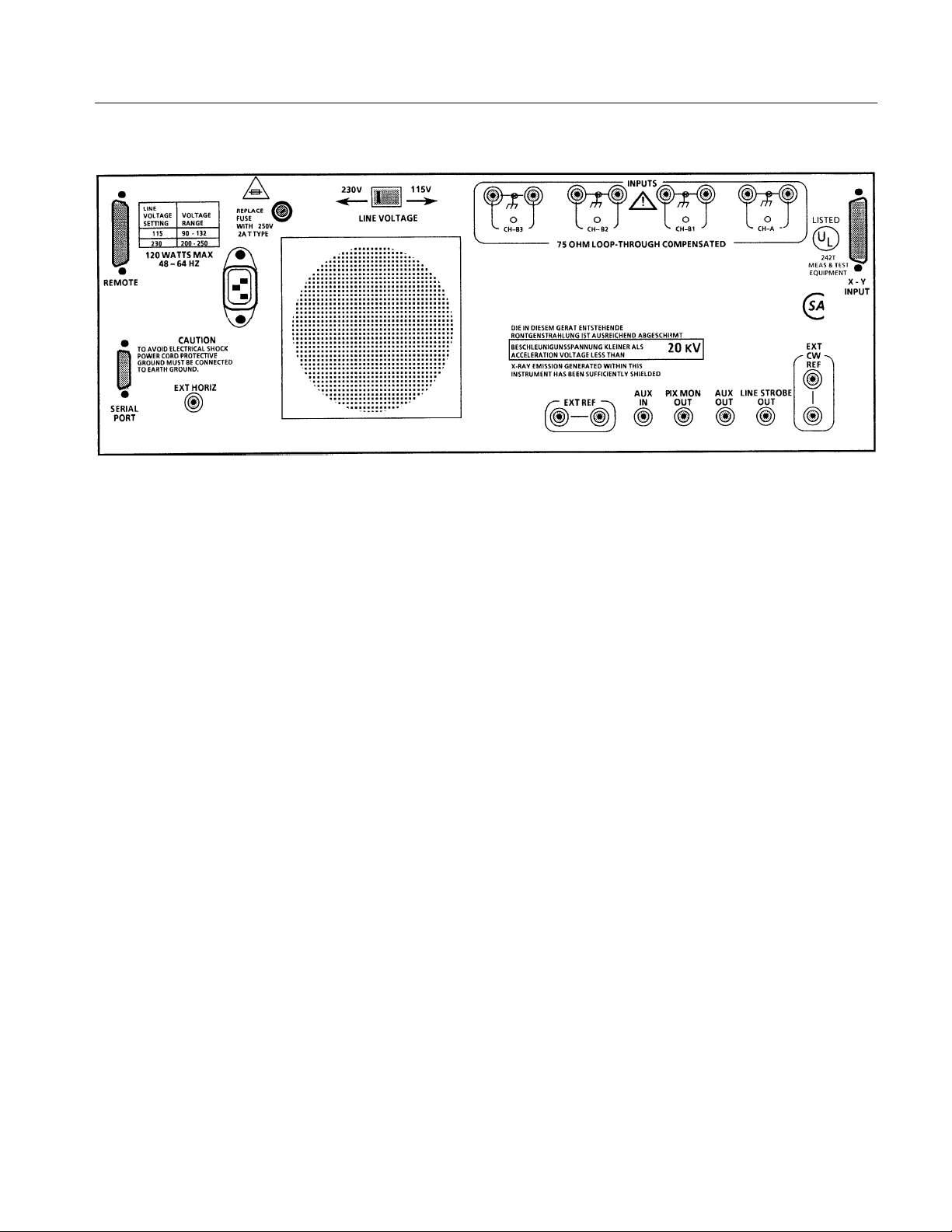
Figure 2–1: Rear panel for the Tektronix 1780R-Series Measurement Set
Installation
EXT REF. High impedance bridging loop through connector for either composite
sync or black burst.
AUX IN. 75 W input for video signals. Insertion point follows the internal filters.
AUX OUT. 75 W video signal output just prior to the filters. Can be used with
the AUX IN to design custom filters.
PIX MON. 75 W output to drive a picture monitor, signal is output prior to filters
and has a bright-up pulse added when line select is used.
LINE STROBE. A 75 W output that provides a pulse for the selected line(s)
when line select is used. Can also be configured to output the Field 1 pulse, see
Table 2–3 (J1103).
CW. High impedance bridging loop-through input for continuous subcarrier
signal. Provides an external phase reference signal.
REMOTE. 15-pin D-type connector used as a ground closure interface for
remote control of key functions. See Figure 2–4.
SERIAL PORT. 9-pin D-type connector that provides a serial interface, using
RS422A or RS232D control, for remote control of Microprocessor-controlled
functions. See Figure 2–5.
1780R-Series Service Manual
X – Y. A 15-pin D-type connector used as a high impedance input for the 600 W
balanced audio. See Figure 2–6.
2–3
Page 46

Installation
Installation Requirements
The 1780R-Series is designed for efficient use of rack space. It can be mounted
flush with other equipment, eliminating the need for air circulation above and
below the cabinet. It should not be mounted flush with equipment that is a
significant heat source, because heat conducted through the cabinet can raise the
internal temperature of the instrument beyond its ability to cool itself.
Cooling air for the 1780R-Series is pulled into the instrument through a
rear-panel fan and exhausted through the cabinet sides. Most equipment racks
provide enough space, along side the instruments, to allow heated air to escape
from this instrument.
Before installing the instrument in the rack, be sure that the cooling fan blades
are un-obstructed and turn freely.
A minimum rear panel clearance of 1-1/2 inches is required to connect BNC
cables.
Front-panel clearance of at least 20 inches is required to remove the instrument
from its rack mounting cabinet.
Electrical Installation
Power Source
Mains Frequency and
Voltage Ranges
This instrument is designed to operate from a single-phase power source having
one of its current-carrying conductors at or near earth-ground (the neutral
conductor). Only the Line conductor is fused for over-current protection.
Systems that have both current-carrying conductors live with respect to ground
(such as phase-to-phase in multiphase systems) are not recommended as power
sources.
The 1780R-Series operates over a frequency range of 48 to 64 Hz, and at a
nominal mains voltage of 115 VAC or 230 VAC. The factory setting, 115 V or
230 V, is marked on the rear-panel mains switch. See Figure 2–2. Be sure the
instrument is operated with the selected mains voltage.
2–4
1780R-Series Service Manual
Page 47

Figure 2–2: Settings for the rear-panel mains selector switch
Installation
Operating Options
In addition to being able to configure the 1780R-Series through user interaction
with a series of CRT-presented menus, there are some specific operating
situations that can be selected by changing internal plug jumpers or Dual-InlinePackage (DIP) switches. These provide for some specific conditions that are not
anticipated to change on a regular basis. For most applications, the factoryinstalled plug jumper and DIP switch settings will be adequate. Tables 2–3
through 2–5 list the internal plug jumpers and DIP switches, by name, and detail
their operation.
Some of the plug jumpers are for maintenance use only. They are designated in
the following tables with a } symbol. When setting up the instrument for
operation they should be left set as they are. Installing jumpers on open pins or
removing already installed maintenance jumpers can disable the instrument.
The plug and the jumper portions of the plug jumpers, in most cases, have pin
one designated by a small triangle.
CAUTION. Be sure that you move only the operation selecting plug jumpers or
DIP switches. Installing or removing Maintenance jumpers or changing the
setting of Maintenance DIP switches will disable normal operation.
1780R-Series Service Manual
2–5
Page 48
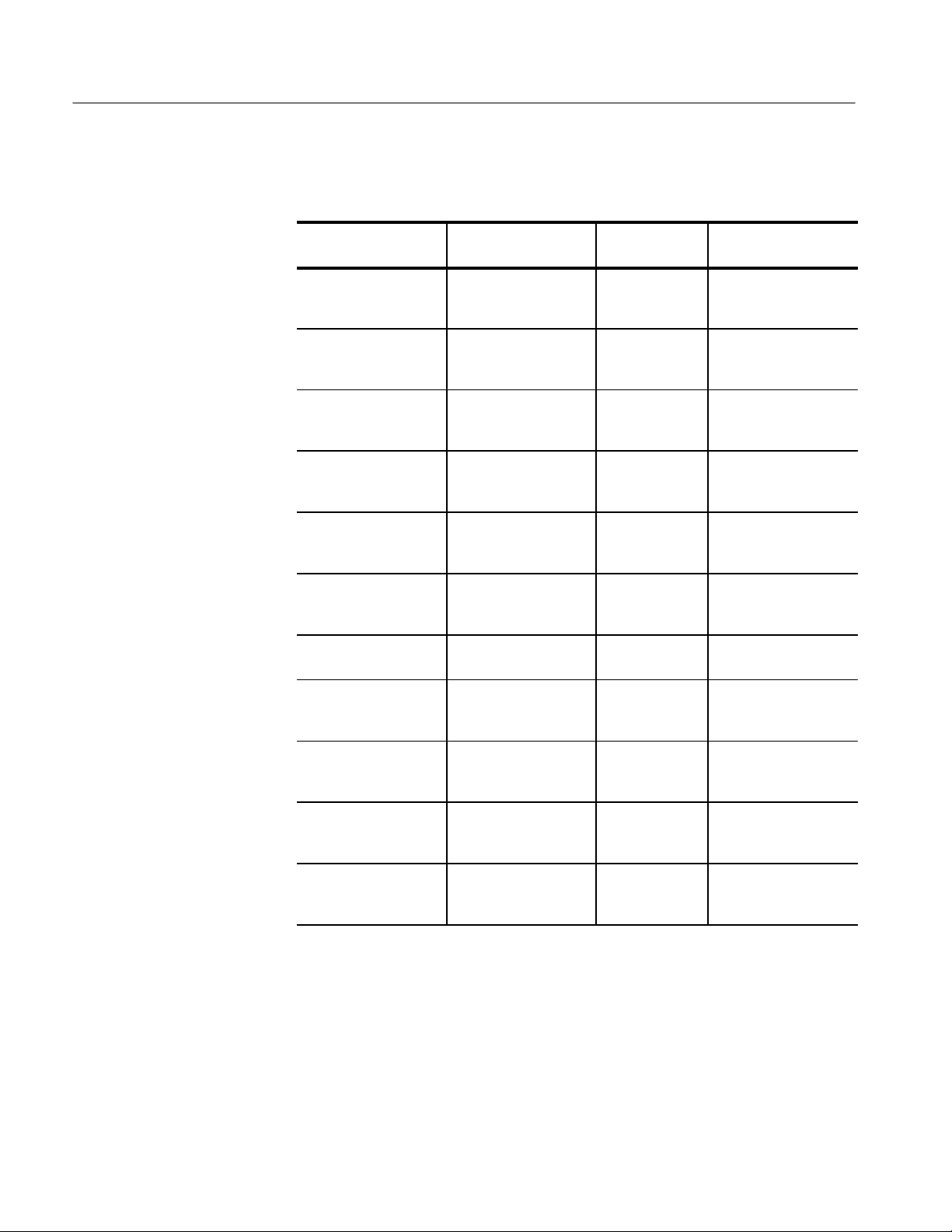
Installation
T able 2–3: Plug Jumpers for Waveform Board (Assembly A2)
(Schematic Diagrams 3 through 15)
Jumper
Number
J192
<9>
J585
<10>
J858
<9>
J694
<10>
J865
<9>
J866 & J867
<9>
J986
<15>
Name Plug Position Purpose
Remote Sync Polarity 1-2 {
2-3
RGB YRGB 1-2
2-3 {
Sound-in-Syncs 1-2 {
2-3
NTSC PAL 1-2
2-3
Sync for Vector Clamps 1-2 {
2-3
Sync for Waveform
Clamps
SCH Course Adjust Varies with the
1-2 { & 1-2 {
2-3 & 2-3
circuits.
Positive
Negative
3-Step RGB Parade
4-Step YRGB Parade
Normal
Sound-in-Syncs
NTSC (1780R)
PAL (1781R)
Reference as source
Input Signal as source
Reference as source
Input Signal as source
4-position jumper set up
during calibration
J1081
<14>
J1085
(Active in NTSC only)
<14>
J1103
<7>
J1483
<8>
{
Factory installed position.
Frame Pulse Select 1-2 {
2-3
SCH Display Mode 1-2 {
2-3
Line Strobe 1-2
2-3 {
Sound-in-Syncs 1-2 {
2-3
Internal
Ext. Video
Double
Single
Line Select
Field 1 Pulse
Normal
Sound-in-Syncs
2–6
1780R-Series Service Manual
Page 49

T able 2–4: Plug Jumpers and DIP Switch on the Microprocessor Board
(Assembly A5) (Schematic Diagrams 16 through 19)
Jumper
Number
J342
<16>
Name Plug Position Purpose
mProcessor Restart
Maintenance }
Removed {
Installed
Normal operation
Non-maskable interrupt to
processor
Installation
J344
<16>
J453
<17>
S385
<19>
{
Factory installed position.
}
Special maintenance use only.
mProcessor Reset
Maintenance }
RAM Part Selection Removed {
Special purpose
4-position DIP switch
Removed {
Momentary Closure
Installed
1
2
3
4
Normal operation
Resets processor (Used
with a factory startup
DEBUG program)
128 K RAM installed
512 K RAM installed
Open = NTSC
Closed = PAL
Open = Password
Closed = No password
} Open = Norm. Oper.
Closed = DEBUG
Not used.
T able 2–5: Plug Jumpers for Vectorscope Board (Assembly A6)
and Oscillator Board (Assembly A7)
1780R-Series Service Manual
Jumper
Number
J108 (A6)
<29>
J205 (A6)
<29>
J321 (A6)
<27>
Name Plug Position Purpose
X Input Gain Removed {
Installed
Y Input Gain Removed {
Installed
Center Dot Blanking 1-2
2-3_ {
X gain is normal
X gain is in High Gain position
Y gain is normal
Y gain is in High Gain position
Center dot unblanked
Center dot blanked
2–7
Page 50

Installation
T able 2–5: Plug Jumpers for Vectorscope Board (Assembly A6)
and Oscillator Board (Assembly A7) (Cont.)
Jumper
Number
J320 (A7)
<34>
{
Factory installed position.
Diff Phase Display 1-2 {
2-3
PurposePlug PositionName
Double (H)/4
Single (V)/2
Floating Video Input
Connectors
The video input connectors can be isolated from ground to increase hum
rejection. When grounding screws are removed (and stored in the blank holes)
the input amplifiers have a common mode input for ac hum that is introduced
from an external source. See Figure 2–3. See Theory of Operation for more
information.
NOTE: The illustration shows the grounding
screws in the ground positions.
Figure 2–3: Upper right portion of the 1780R-Series rear panel, showing the location
of the four loop-through signal inputs
2–8
1780R-Series Service Manual
Page 51

Installation
REMOTE Connector
The rear-panel REMOTE connector is a subminiature 15-pin D-type receptacle
with female contacts. All the active remote control lines can be forced low by
remote ground closures or TTL levels.
Pin assignments for the REMOTE connector are shown in Figure 2–4.
Remote Operation
Figure 2–4: Remote connector and the function of each pin. A / before a function
indicates a low to activate
The 1780R-Series REMOTE connector provides access to several operating
modes plus the first eight Preset front panels which can also be accessed through
the front-panel PRESET selection and touch screen menus.
Table 2–2 describes the remote functions that may be selected. A logic NOT, or
low, means that the specified REMOTE pin must be low (0 V to +0.8 V) to
achieve that function. A high means that the pin is left open (with no signal), or
accepts a 2 V to 5 V signal, to achieve the desired function.
Remote Sync input (pin 10) works with TTL level square waves, and requires an
input signal of approximately 30–60 Hz (NTSC) or 25–50 Hz (PAL) to
synchronize the 1780R-Series. Polarity is internal jumper selected as shown in
Table 2–3.
Forcing pin 2 of the REMOTE connector low disables normal sweep and
connects the RGB staircase signal (input on pin 1) to the horizontal Mag
Amplifier. A +10 V staircase input will deflect the trace approximately 9
graticule divisions. Sweep length, per line or field, is approximately 33% of
normal for an RGB parade display and 25% of normal for a YRGB parade
display. See Table 2–3 (J585) for display selection information.
1780R-Series Service Manual
2–9
Page 52

Installation
SERIAL Interface
Connector
Serial Remote Information
The rear-panel SERIAL interface connector is a 9-pin, sub-miniature, D-type
connector. It is used as an RS422A or RS232D interface to the 1780R-Series
microcontroller, drivers for both interfaces are resident. RS422A is a balanced
voltage digital interface, while RS232D is a serial binary data interchange.
Figure 2–5 shows the rear-panel SERIAL connector pin assignments.
Figure 2–5: Serial interface connector showing the function of each pin
1780R-Series instrument configurations can be stored at (and retrieved from) a
remote location by connecting a host computer to the rear-panel SERIAL port
that supports RS-232 or RS-422 standards. Because RS232D calls for a 25-pin
connector, a special 9-pin to 25-pin adapter cable will be required to access this
operating mode, unless some form of 9-pin to 9-pin interface is being used.
25-Pin to 9-Pin RS232D
Adapter
All front-panel controls are operative in their usual manner when serial remote
operation is employed, which allows local modification when desired. Front-panel LED indicators show current switch settings, even when serial remote control
is used.
Serial Data Format. 8 data bits, 1 stop bit, no parity.
Baud Rates. 300, 1200, 9600, 19200. The baud rate selection is made through
page 3 of the touch screen Configure menu.
The data stream transmitted to and from the host (representing the current
1780R-Series settings) consists of 512 bytes, followed by a one-byte checksum.
All data bytes are in the range of Hex 20 to Hex 7F, so that they are printable
ASCII characters.
In order to use the SERIAL interface with an RS232D compatible host computer
that has a standard RS232D 25-pin connector, an adapter will be required. Both
connectors are the sub-miniature D-type and should be readily available from
most local electronic supply outlets. The adapter connects pin 2 to 2 and pin 3 to
3 of the connectors along with providing a common signal ground between pin 5
2–10
1780R-Series Service Manual
Page 53

Installation
(of the 9-pin male connector) and pin 7 (of the 25-pin female connector). In
addition, pins 4 and 5 and pins 6, 8, and 20 of the 25-pin connector will need to
be wired together. See Figure 2–6.
Command Set
Figure 2–6: RS232D serial interface adapter diagram
The command set for the the 1780R-Series SERIAL interface is shown in
Table 2–6.
T able 2–6: Serial Remote Commands
Command* Function Results
#U or #u UPLOAD 1780R-Series sends a stream of data, representing the
current instrument configuration, to the host computer.
#D or #d DOWNLOAD 1780R-Series expects a stream of data representing an
instrument configuration of the same form that was
uploaded.
#P or #p PARTIAL
DOWNLOAD
* The # character indicates a remote control command. All transmissions are ignored
until this character is received.
1780R-Series expects a stream of data representing an
instrument configuration, with the knob settings (focus,
intensity, etc.) not affected.
1780R-Series Service Manual
2–11
Page 54

Installation
Responses from the 1780R-Series SERIAL interface are shown in Table 2–7.
T able 2–7: Serial Remote Responses
Command Description
A The transmission was successful (ACK)
C Command not known. (The # character was received, but was not followed by a
U, u, D, d, P, or p.)
D Bad data received (all expected data consists of ASCII printable characters).
H Bad internal checksum.
N Bad transmission checksum (NACK)
T Timed out (the process took too long to complete).
V Software version number mismatch.
XY INPUT Connector
The rear-panel XY INPUT connector is a 15-pin, sub-miniature, D-type
connector that provides input to the Horizontal and Vertical (X and Y) Amplifiers. They are balanced (differential), DC-coupled, high impedance (>20 kW),
un-terminated inputs provided for audio applications. If AC coupling is desired,
external capacitors are required. These inputs are factory calibrated for 0 dBm in
600 W but can be adjusted for any 600 W system between 0 and 12 dBm. See
Figure. 2–7.
0 dBm is equal to 1 mW or 2.19 V peak-to-peak in 600 W.
12 dBm is equal to 15.8 mW or 8.72 V peak-to-peak in 600 W.
To calibrate the 1780R-Series for a system other than 0 dBm, perform step 38 of
the Adjustment Procedure (Section 6) using a 1 kHz sine wave of the appropriate
amplitude.
Inputs can be driven single-ended by driving either the + or – X and Y inputs
with the opposite polarity inputs grounded.
In addition, a single-ended, high-gain mode can be used for other, primarily
non-audio, applications. It can be accessed by installing plug jumpers on J108
and J205 (on the Vectorscope board, see Table 2–5) and inputting the signal on
the +X and +Y inputs with the –X and –Y inputs grounded.
2–12
1780R-Series Service Manual
Page 55

Installation
Mechanical Installation
15
9
8
1
Figure 2–7: Rear-panel XY connector diagram showing the function of each pin
All qualification testing for the 1780R-Series was performed with the rackmount cabinet installed. To guarantee compliance with specifications, the
instrument should be operated in a cabinet, either the rack-mount cabinet or the
portable case (1780F02). The 1780F02 case has a handle and front and back
covers. The front and back covers provide protection for the instrument during
transportation and storage.
1780R-Series Service Manual
NOTE. Cabinet drawings are provided for installation information only, and are
not to scale. All dimensions are in inches.
The rack-mounting cabinet is a standard accessory; all instruments are factory
shipped in this cabinet. The portable case (1780F02) is available from Tektronix
as an Optional Accessory. It, as does the rack-mounting cabinet, provides the
proper electrical environment for the instrument, supplies adequate shielding,
minimizes handling damage, and reduces dust collection within the instrument.
2–13
Page 56

Installation
Rack Mounting The 1780R-Series
The 1780R-Series rack-mounting cabinet is designed for permanent mounting.
The instrument slides in and out of the cabinet with relative ease. The instrument
is secured in the cabinet with four 6–32 TORXR drive screws. See Figure 2–8.
Figure 2–8: Location of the four screws that secure the instrument to rack
mounting cabinet or portable case
Rack Installation
WARNING. Do not attempt to carry a cabinetized instrument without installing
the rear-panel mounting screws. There is nothing to hold the instrument in the
cabinet if it is tipped forward.
The 1780R-Series is a three rack-unit (5.25 inch) high, 19 inch wide unit. It
requires no vertical rack space above or below the unit. A front clearance, for
removal from the rack, of at least 18 inches is required. BNC connectors, on the
rear panel, extend approximately 0.6 inches, making it necessary to have 1 inch
or more of rear clearance to have enough room to cable the instrument. See
Figure 2–9 for rack mounting dimensions.
NOTE. For ease of installation, place the nut bars to the outside of the adjustable
brackets and drive the screws from the center into the nut bars.
2–14
1780R-Series Service Manual
Page 57
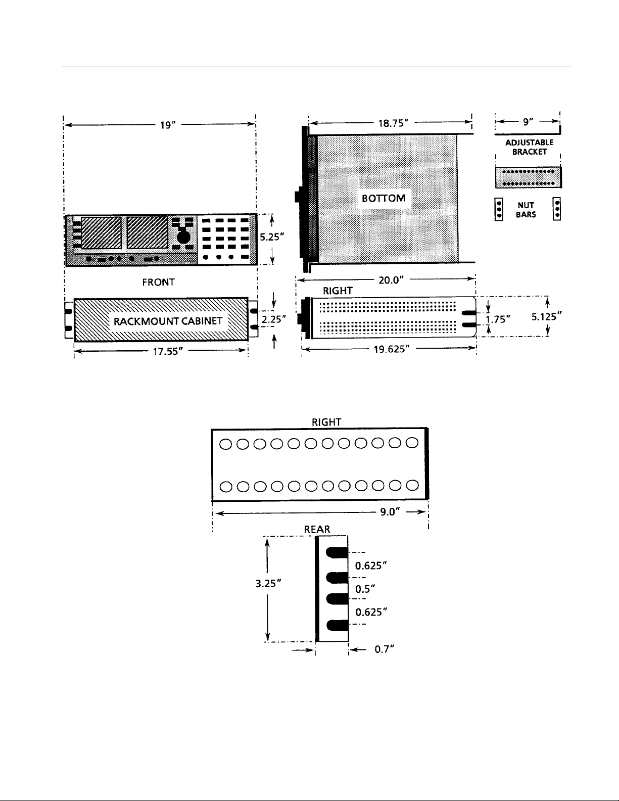
Installation
Figure 2–9: Dimensions used for rack mounting the 1780R-Series Video Measurement Set
1780R-Series Service Manual
Figure 2–10: Dimensions of the adjustable rear rackmounting bracket
2–15
Page 58

Installation
To install the instrument in the rack: First remove the four securing screws and
take the instrument out of the rack-mounting cabinet. (All 1780R-Series
instruments are shipped in the rack-mounting cabinet to provide extra shipping
protection.) Once the instrument is out of the cabinet, mount the front of the
cabinet in the rack, using four 10–32 TORXR screws. Cabinet front slots are
spaced, and wide enough, to accommodate standard racks. Next, mount the
adjustable brackets to the rear rack section. See Figure 2–10 for bracket
dimensions. Then mount the adjustable brackets to the rack-mount cabinet using
four 10–32 TORXR screws, four number 10 flat washers, and the nut bars. See
Figure 2–11 for more assembly detail. Finally, re-install the four 6–32 screws
that secure the instrument to the rack-mounting cabinet. See Figure 2–8.
2–16
Figure 2–11: Installing rear rack-mounting brackets for rack applications of depths
from 18 to 24 inches
1780R-Series Service Manual
Page 59

Installation
Portable Case Installation
The 1780R-Series can be mounted in a portable case. This case is an optional
accessory, and is nomenclated 1780F02. The portable case consists of a metal
cabinet with feet, front elevating bail, carrying handle (all installed), and front
and back protective covers. See Figure 2–12. Instrument mounting in the
portable case is identical to that of the rack-mount cabinet. See Figure 2–8 for
location of the mounting screws.
The 1780F02 portable case has sufficient length (SN B010500 for this portable
case; not the instrument) to protect the rear-mounted fan, connectors, cable
connections, and power cord when the instrument is placed on its rear during
operation.
The feet located on the bottom and left sides of the case allow the instrument to
be placed in either of these positions for operation, transportation, or storage.
The front and rear covers are identical so they are interchangeable.
Initial Calibration
1780R-Series Service Manual
Figure 2–12: Portable case for the 1780R-Series Video Measurement Set. Case has
handle, feet, and an elevating bail along with two panel covers
Once the 1780R-Series has been installed in the rack or portable case, some
simple calibration steps will need to be performed. An accurate Color Bar signal
and a 1 V square wave are the only external signals required to perform the steps
in the procedure that follows. The procedure used here is similar to the one
provided to operating personnel in the Operator’s Manual.
2–17
Page 60

Installation
In the procedures that follow the 1780R-Series front-panel control names are in
ALL CAPITALS and menu items are enclosed in <>.
Calibration Menu
Information
Waveform Calibration
Information
The Calibration menu is available for both vector and waveform, and uses both
CRTs.
Pushing the front-panel CALIBRATE button provides access to the menu.
Several calibration features can be selected using the touch screen. Refer to the
following Waveform and Vector calibration procedures.
To toggle the display between vectorscope and waveform calibration, push the
buttons under the CRTs. When waveform is selected, the waveform calibrator is
displayed on the right CRT, with waveform menu selections on the left CRT
(vectorscope display blanked). When vectorscope is selected, the arrangement is
reversed.
The internal calibrator signal is selected by touching the <CAL SIGNAL> area
of the screen until <ON> is outlined. It automatically reverts to <OFF> when the
Calibration menu is exited and must be reselected (if desired) when the menu is
reentered. (CAL signal is not available in <CAL AMPL ZERO SET>.)
An external 1.0 Volt reference signal is required to adjust the External Horizontal
Input gain.
VOLT CURSORS ZERO SET, CAL AMPL ZERO SET, and HORIZ POSITION KNOB CAL provide menu displays on the Waveform CRT. The selection
is indicated by a box on the Vectorscope CRT, and the large knob function is
circled on the Waveform CRT.
Waveform Calibration
2–18
Procedure
HORIZ CAL, EXT HORIZ CAL, VERT CAL, READOUT INTENSITY, and
TRACE ROTATION will be circled, when selected, to indicate large knob
assignment.
Changes in calibration will be stored when the Calibrate menu is exited. Exit by
pushing the CALIBRATE menu button or by pushing another menu button.
NOTE. Preparation is usually not required before performing this procedure.
However, if something occurs to cause calibration data to be reset or invalid
(such as loss of Non-volatile memory or installation of new software), then Step
3 of the ADJUSTMENT PROCEDURE must be performed prior to the Initial
Calibration Procedure.
1. Apply a video signal to a 1780R-Series input channel and select that channel
for display. Check that the input channel is terminated into 75 W.
1780R-Series Service Manual
Page 61

Installation
2. Push the front-panel CONFIGURE button and touch <FIXED CAL AMPL>
until 1000 (1.0 Volt) is outlined.
3. Push the front-panel CALIBRATE button. Push the button below the
Waveform CRT.
4. <READOUT INTENSITY> will be circled on the Vectorscope CRT. Use the
large knob to adjust intensity. (The front-panel INTENSITY control adjusts
signal intensity only. Readout intensity must be adjusted through the
Calibration menu.)
NOTE. Step 5 is to be performed for instruments SN B020244 and below only.
5. Touch <HORIZ POS KNOB CAL> to calibrate the HORIZ POS knob. A
menu will be displayed on the Waveform CRT. Center the HORIZ POS
control by turning the control and then releasing it, allowing the spring (not
necessarily the signal display) to return to midpoint of its range. Then touch
the area labeled: <CENTER HORIZONTAL POSITION KNOB, THEN
PRESS HERE>. This tells the microprocessor that the knob is now at the
midpoint, or zero point, of its range. This zero point is referred to as the
Dead Zone, and its tolerance can be varied by touching <INCREASE> or
<DECREASE>. The value changes in single step increments from the
smallest possible setting of 1 unit up to 16 units, and current value is shown
on the readout. A beep sounds when the Dead Zone has been increased or
decreased as much as possible. If the Dead Zone is increased, the control
must be turned slightly before it will respond, but will also return to center
more readily after it is turned.
1780R-Series Service Manual
6. Touch <TRACE ROTATION> to obtain a test axis, then use the large knob
to adjust trace rotation. Align the horizontal lines of the electronic graticule
with the Waveform CRT graticule horizontal lines.
7. Touch <CAL AMPL ZERO SET> to obtain a menu on the Waveform CRT
for adjusting the calibrator zero level. Adjust the large knob to overlay the
two waveforms. Press the front-panel REFERENCE SET button to record
this zero setting.
8. Touch <VOLT CURSORS ZERO SET> to obtain a voltage cursor menu on
the Waveform CRT. Use the large knob to move the cursors, touching the
<CURSOR 1 / CURSOR 2> area to toggle between Cursors One and Two.
When cursors are aligned, press REFERENCE SET to reset the displayed
voltage difference to zero.
9. Touch <CAL SIGNAL ON / OFF> until <ON> is outlined. (Calibration
signal is not available in <CAL AMP ZERO SET>.) Check that the WFM
HORIZONTAL–TWO–LINE sweep is selected and VAR sweep is off.
2–19
Page 62

Installation
10. Select <VERT CAL> as shown in Figure 2–13. The large knob will now
adjust signal amplitude with respect to the graticule. Adjust for a 1 Volt
display on the Waveform CRT. Leave the CALIBRATE button set to On.
Figure 2–13: Waveform Calibration menu display
11. Select an input channel that has no signal applied. Check that TWO LINE
sweep is selected.
a. Push the front-panel TIME button to turn on the timing cursors. Reduce
the trace (display) intensity if necessary to view the timing cursor dots.
b. Touch the timing cursors area of the screen until <CURSOR 1> is
outlined. Use the large knob to move Cursor 1 approximately 1 division
in from the left edge of the graticule.
c. Select <CURSOR 2> and use the large knob to move it 100 msec to the
right of Cursor 1, as indicated on the CRT readout.
d. Push the CALIBRATE button. Touch <HORIZ CAL>. The large knob
will now adjust sweep length (time) with respect to the graticule. Adjust
for 10 divisions between cursor dots.
e. Push the front-panel TIME button to turn off the timing cursors.
Readjust the trace (display) intensity if necessary.
2–20
1780R-Series Service Manual
Page 63

Installation
12. Apply a 1.0 volt signal to the EXT HORIZ input. Touch <EXT HORIZ
CAL>. The large knob will now adjust sweep length (time) with respect to
the graticule. Do not change the MAG setting (automatically set to 100
mV/div). Adjust the large knob for a horizontal display of 10 divisions.
13. Press the CALIBRATE button to exit the menu.
Vectorscope Calibration
Information
Vectorscope Calibration
Procedure
READOUT INTENSITY, TRACE ROTATION, and GAIN CAL (GAIN 1 CAL
/ GAIN 2 CAL for NTSC) will be circled when selected, to indicate large knob
assignment.
The oscillator signal is selected by touching the <CAL OSC> area of the screen
until <ON> is outlined. It automatically reverts to <OFF> when the Calibration
menu is exited and must be reselected (if desired) when the menu is reentered.
Changes in calibration will be stored when the Calibrate menu is exited. Exit by
pushing the CALIBRATE menu button or by pushing another menu button.
NOTE. Preparation is usually not required before performing this procedure.
However, if something occurs to cause calibration data to be reset or invalid
(such as loss of Non-volatile memory or installation of new software), then Step
3 of the ADJUSTMENT PROCEDURE (SECTION 6) must be performed prior to
the Initial Calibration Procedure.
1. Apply a 75% color bar signal to the 1780R-Series CH A INPUT connector.
For NTSC only: Use a signal with 7.5% setup. Check that CH A INPUT
loop-through is terminated into 75 W.
1780R-Series Service Manual
2. Select INPUT–CH A on the 1780R-Series front panel.
3. Push the front-panel CONFIGURE button to enter the Configure menu.
Touch the <PAGE> area of the screen until <2> is outlined. Check that
<BARS> <75%> is outlined.
4. Push the front-panel CALIBRATE button to enter the Calibration menu.
5. Push the button under the left CRT (LED will light) to select Vectorscope
calibration.
6. <READOUT INTENSITY> will be circled on the Waveform CRT. Use the
large knob to adjust intensity. (The front-panel INTENSITY control adjusts
signal intensity only. Readout intensity must be adjusted through the
Calibration menu.)
2–21
Page 64

Installation
7. Touch <TRACE ROTATION> to obtain a test axis, then use the large knob
to adjust trace rotation on the Vectorscope CRT. Align the horizontal lines of
the electronic graticule parallel with the Vectorscope CRT graticule.
8. Touch <CAL OSC> until <ON> is outlined. While the cal oscillator is on,
the V axis switcher is enabled and 75% bars are selected (with 7.5% setup
for NTSC).
a. For 1780R (NTSC) only: Touch <GAIN 1 CAL (SETUP)> on the
Waveform CRT. See Figure 2–14. The large knob will now adjust
vectorscope gain. Use the large knob to match the circle to the compass
rose. Touch <GAIN 2 CAL (NO SETUP)>. Use the large knob to match
the circle to the compass rose. Touch <GAIN 1 CAL (SETUP)> to return
to this mode.
b. For 1781R (PAL) only: Touch <GAIN CAL> on the Waveform CRT.
See Figure 2–15. The large knob will now adjust vectorscope gain. Use
the large knob to match the circle to the compass rose.
9. Touch <CAL OSC> until <OFF> is outlined.
10. Push the front-panel PHASE SHIFT button to On. Turn the large knob to
properly position the burst and color vectors to their graticule marks on the
Vectorscope CRT. Press the PHASE SHIFT button to exit this mode.
a. For 1780R (NTSC) only: Check that <GAIN 1 CAL (SETUP)> is
selected. Verify that the color vector dots are in their boxes. Then, set the
NTSC generator Setup button to 0%. Select <GAIN 2 CAL (NO
SETUP)> and verify that the color vector dots are in their boxes. Set the
NTSC generator Setup button to 7.5%.
b. For 1781R (PAL) only: Check that <GAIN CAL> is selected. Verify that
the color vector dots are in their boxes.
11. Push the front-panel CALIBRATE button to exit the menu.
2–22
1780R-Series Service Manual
Page 65

Installation
Figure 2–14: 1780R (NTSC) Vectorscope Calibration menu display with CAL OSC on
Figure 2–15: 1781R (P AL) Vectorscope Calibration menu display
1780R-Series Service Manual
2–23
Page 66

Installation
Repackaging
Identification Tag
Repackaging for Shipment
If the instrument is to be shipped to a Tektronix Service Center, attach a tag to
the instrument showing:
1. Owner (with complete address) and the name of the person at your firm that
can be contacted.
2. Instrument serial number and a description of the service required.
Repackaging the instrument in the original manner provides adequate shipping
protection (See Figure 2–16). If the original packaging is not available or is unfit
for use, repackage the instrument as follows:
1. Obtain a corrugated cardboard carton whose inside dimensions are at least
six inches greater than the dimensions of the instrument, for cushioning. The
shipping carton should have a test strength of at least 275 pounds.
2. Surround the instrument with polyethylene sheeting to protect the finish.
3. Cushion the instrument on all sides by tightly packing dunnage or urethane
foam between the carton and the instrument.
4. Seal the carton with shipping tape or an industrial stapler.
2–24
1780R-Series Service Manual
Page 67

Installation
Figure 2–16: 1780R-Series repackaging
1780R-Series Service Manual
2–25
Page 68

Installation
2–26
1780R-Series Service Manual
Page 69
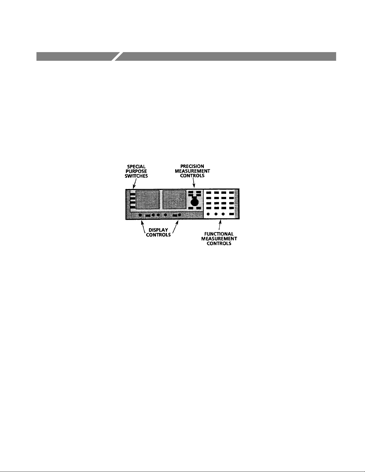
Operating Information
In order to effectively service the 1780R-Series it is essential to understand how
the controls work. Controls and switches fall into one of four groups; Display
(Scale, Focus, Intensity and Positioning), Special Purpose (Preset, Measure,
Configure, and Calibrate), Precision Measurement (Cursors, Phase, Line Select,
etc., which support the assignable measurement control), and the Functional
Measurement controls and switches (Input and Reference switching, etc., from
the right front panel). See Figure 2–17.
Figure 2–17: Simplified representation of the 1780R Series showing the location of
the control groups
When servicing this instrument, all of the front-panel controls will be used at one
time or another. In most cases the function of a control is obvious from the
front-panel nomenclature; however, there are cases where some extra explanation
is required. For example, the display controls (FOCUS, SCALE, INTENSITY,
VERT POS, HORIZ POS), located beneath the CRTs, are functionally switched
between the CRTs.
Figures 2–18 and 2–19 are used in conjunction with the following explanations
of the control functions.
1780R-Series Service Manual
2–27
Page 70
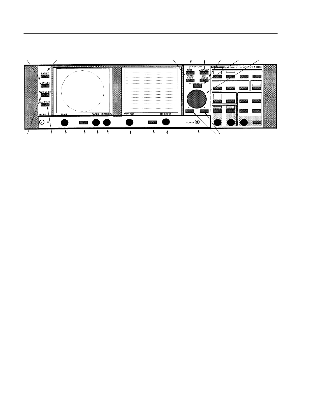
Operating Information
91
1
1
1615
13 14
0
11 12
Figure 2–18: Front panel of the 1780R-Series Video Measurement Set
Front-panel Controls
With the exception of the POWER switch, all of the switches and controls on the
1780R-Series front panel fall into the general groupings of Special Purpose,
Precision Measurement, Display, or Functional Measurement. Numerals by each
control name are supplied to assist in locating the control in the two associated
figures.
7
12348567
19
8
Display Controls
1. POWER. Self indicating positive push and release switch that changes the
1780R-Series from standby to operate. When power cord is connected to the
instrument, it is automatically in standby state.
2. Left (button). Illuminated switch that assigns the common FOCUS, SCALE,
INTENSITY, and POSITION controls to operate with the left-hand CRT.
Previous setting of these controls is stored and returned when the button is
first pushed. (In the factory-shipped configuration this button causes only a
temporary shift in control, timing out and returning control to the right CRT
after selection.)
3. Right (button). Illuminated switch that assigns the common FOCUS,
SCALE, INTENSITY, and POSITION controls to operate with the righthand CRT. Previous setting of these controls is stored and returned when the
button is first pushed. (As factory-shipped, control reverts to this button after
a timeout for the left CRT display.)
4. FOCUS. Adjusts beam for the selected CRT to provide optimum definition.
5. SCALE. Controls the level of graticule illumination for the selected CRT.
6. INTENSITY. Controls display brightness for the selected CRT.
2–28
1780R-Series Service Manual
Page 71

Operating Information
7. VERT POS. Positions the selected display up and down. Positioning range
depends on the display selected; range is much greater for the waveform
monitor displays than it is for the vectorscope displays.
8. HORIZ POS. Positions the selected display left and right. Positioning range
depends on the display selected; range is much greater for the waveform
monitor displays than it is for the vectorscope displays.
Special Purpose Switches
Precision Measurement
Controls
9. PRESET. Lighted momentary contact switch that turns on or off a list of
preset front-panel setups that the operator can program and select for
repeated measurements.
10. MEASURE. Lighted momentary contact switch that brings up menu
selections for factory pre-programmed measurement setups.
11. CONFIGURE. Lighted momentary contact switch that calls up menus to
guide the configuring of the measurement criteria, such as clamping,
coupling, etc.
12. CALIBRATE. Lighted momentary contact switch that brings up a menu to
provide calibration adjustments and signal choices for instrument calibration.
13. TIME CURSORS. A single momentary contact on/off switch enabling the
timing cursors, which use the Precision Measurement knob, or the <>
buttons. Time Cursors switch has a built-in indicator.
14. VOLTAGE CURSORS. A single momentary contact on/off switch enabling
the voltage cursors, which use the Precision Measurement knob, or the <>
buttons. Voltage Cursors switch has a built-in indicator.
15. PHASE SHIFT. A single momentary contact on/off switch enabling the
precision phase shift measurements, which use the Precision Measurement
knob, or the <> buttons. Phase Shift switch has a built-in indicator.
1780R-Series Service Manual
16. LINE SELECT. A single momentary contact on/off switch enabling the line
select function, which displays the selected line (first in a multiple line
display, or brightened in a field display). Alpha-numeric readout indicates
the selected line and field on the waveform monitor CRT. Line Select switch
has a built-in indicator. Selection of the exact line and field is accomplished
through the Precision Measurement knob, or the <> buttons.
17. REFERENCE SET. Used with the Phase Shift mode to store a reference
phase. REFERENCE SET is used in the VOLTAGE CURSORS mode when
RELATIVE is selected. It is also used in the LINE SELECT mode to access
line 19 in the vertical interval.
18. Knob. The Precision Measurement control operates with the four functions
selected by the preceding switches. Provides continuously adjustable range
to the selected measurement.
2–29
Page 72

Operating Information
19. < >. A pair of momentary contact switches that provide stepped levels that
duplicate the function of the Precision Measurement control.
2–30
1780R-Series Service Manual
Page 73

Functional Measurement Controls
Functional Measurement Controls are shown in Figure 2–19. Note that the
numerical entries are enclosed in rectangles instead of the circles that were used
in Figure 2–18.
123 4 8
5
6
Operating Information
11
12
Left Display
7
9
10
13
14
19 20 18 17 16 15
Figure 2–19: The right front panel for the Tektronix 1780R-Series, showing the
Functional Measurement Controls
1. VECT / SCH. Momentary contact switch that cycles through selections of
the Vector, SCH phase or a combination of both for display on the vectorscope CRT. Small front-panel light-emitting diodes indicate the selected
display.
1780R-Series Service Manual
2. XY / PIX. Momentary contact switch that selects the XY or picture monitor
display for the vectorscope CRT. Can be selected when SCH phase or Vector
display is operating. Small front-panel light-emitting diodes indicate the
selected display.
2–31
Page 74

Operating Information
Right Display
Input
3. PARADE / OVERLAY. Momentary contact switch that cycles through
selections of sequential displays that can be up to 3 lines or 3 fields on a
single display, depending on the selected waveform sweep.
4. WFM / WFM + CAL. Momentary contact switch that cycles through
selections of standard waveform or waveform plus calibrator signal for
display on the waveform monitor CRT. Small front-panel light-emitting
diodes indicate the selected display.
5. CH A / PROBE. Momentary contact switch that selects the signal from the
rear-panel Channel A loop-through input or the front-panel Probe input for
display on both CRTs. Small front-panel light-emitting diodes indicate the
selected display.
6. CH B1 / CH B2 / CH B3. Momentary contact switch that cycles through
selections of the signal from the rear-panel Channel B1, Channel B2, or
Channel B3 loop-through input for display on both CRTs. Small front-panel
light-emitting diodes indicate the selected display.
7. A-B1 / B1-B2 / B1-B3. Momentary contact switch that cycles through the
differential input selections for display. Small front-panel light-emitting
diodes indicate the selected display. Pushing and holding this switch in
provides menu instructions for setting up new differential combinations for
this display.
REF
Filter
8. INT / EXT / CW. Momentary contact switch that toggles between internal
(from incoming video), external (from rear-panel loop-through input) signals
for sync and subcarrier reference. Pushing and holding this switch selects the
rear-panel CW loop-through as a subcarrier reference. Small front-panel
light-emitting diodes indicate the selected reference.
9. FLAT / LUM / CHROM. Momentary contact switch that toggles through
Flat (unfiltered video signal), Luminance (chrominance filtered out), and
Chrominance (luminance filtered out) video signal for display. Small
front-panel light-emitting diodes indicate the selected filter.
Pushing and holding this button selects a multiple filter display. In 2-line or
2-field sweeps the first half of the waveform monitor display will be flat and
the second half will be the luminance filter. In 3-line or 3-field sweep the
order is flat, luminance filter, and chrominance filter. If the button is held in
during 1-line or 1-field sweep the filter reverts to flat.
10. AUX / LPASS / DIFF. Momentary contact switch that toggles through Aux
Video Input (signal is input following the video filters), low-pass filter
(300 kHz bandwidth) and the Differentiated step (rising and falling
2–32
1780R-Series Service Manual
Page 75

Operating Information
transitions) display. Small front-panel light-emitting diodes indicate the
selected filter.
WFM Horizontal
Magnifier
11. ONE / TWO / THREE. Momentary contact switch that toggles through two
sweep positions (1-line or 1-field and 2-line or 2-field; 3-line or 3-field is
activated by holding the button in). Small front-panel light-emitting diodes
indicate the selected number of lines or fields per sweep.
12. LINE / FIELD. Momentary contact switch that toggles between line and
field rate sweeps. Small front-panel light-emitting diodes indicate the
selected sweep range.
13. ON >. Momentary contact switch that turns on the magnifier, and once the
magnifier is on toggles upward through the magnifier ranges.
14. < OFF. Momentary contact switch that toggles downward through the
magnifier ranges. Turns off the magnifier when held in.
A small front-panel light-emitting diode is on whenever the magnifier is
turned on.
15. VAR / SLOW. Momentary contact switch that toggles between Variable
Sweep, Slow Sweep, and Off. Small front-panel light-emitting diodes
indicate if either Slow Sweep or Variable Sweep is turned on.
16. SWEEP RATE. Variable and Slow Sweep both use the associated knob to
provide the control for sweep rate (variable sweep) or sweep duration (slow
sweep).
Gain: Waveform
Gain: Vector
1780R-Series Service Manual
17. VAR / X5. Momentary contact switch that toggles through variable gain, X5
gain, and off for the waveform monitor Vertical Amplifier. Holding this
switch in enables both X5 and Variable Gain. The knob controls the amount
of variable gain.
Small front-panel light-emitting diodes indicate the selected gain.
18. VARIABLE CONTROL. 360_ potentiometer controlling variable gain.
19. VAR / MAX. Momentary contact switch that turns on the Variable Gain,
which is controlled by the knob. Holding in this switch disables the variable
and sets the vectorscope gain to maximum.
20. VARIABLE CONTROL. 360_ potentiometer controlling variable gain.
2–33
Page 76

Operating Information
2–34
1780R-Series Service Manual
Page 77

Page 78

Theory of Operation
Contents of this section are designed to work with the block and schematic
diagrams in Section 9, at the back of this manual. Each schematic diagram
description begins with a small block diagram of the circuits on that page and a
short overview relating the illustration to the circuit theory that follows.
Block Diagrams
The 1780R-Series contains a large amount of circuitry; in order to simplify the
block diagram, it has been split into 5 pages. Each page covers a specific area of
operation. Symbols used on these diagrams are those that have typical use in
instruction manuals for other Tektronix television instruments. In particular:
A number in brackets (< >) denotes the schematic diagram (in Section 9)
where that individual circuit can be found.
Names within the dashed line rectangles are switching functions that are
either activated by front-panel switches or touch-panel menu selections.
Input and output signals that go to another block diagram are identified both
by signal name and the name and number of the block diagram they are
going to or coming from.
Block Diagram 1
Input And Waveform
Vertical
Block Diagram 2
SCH And Waveform
Horizontal
Block Diagram 3
Vectorscope
For example, –REF H SYNC MPU 4 is the reference horizontal sync and is
shown going to the Microprocessor, which is shown on Block Diagram
number 4.
This diagram contains all of the signal input circuitry, DC restorers, signal filters,
and the vertical amplifiers and output for the waveform monitor.
This diagram contains the sync separators (input and reference), ramp generators
(including slow sweep), output amplifiers for the horizontal sweeps, clamp pulse
generator, and SCH identification and output circuits.
This diagram has the vectorscope amplifiers, timing circuits, demodulators, and
output circuits. In addition, the subcarrier regenerator, precision phase shifter, dP
and dG demodulators, digital recursive filter, X-Y, and picture monitor sweeps
also appear here.
1780R-Series Service Manual
3–1
Page 79

Theory of Operation
Block Diagram 4
Microprocessor
Block Diagram 5
Z-axis
Schematic Diagrams
This diagram contains the interface to the front-panel switches, indicators, and
touch panels along with the rear-panel serial and remote connectors. In addition,
it contains circuitry that controls internal switching functions and generates
readout for both CRTs.
This diagram contains the blanking and unblanking functions of the CRTs, their
power supplies and display control circuits, cursor implementations, and the low
voltage power supply circuitry.
Schematic diagrams for this instrument are grouped both functionally and by
etched circuit board. One major exception occurs with Schematic 3, which
contains probe circuitry. Probe input is on the Vectorscope circuit board
(Assembly A6) while the probe output amplifier and DC restorer circuits are on
the Waveform circuit board (Assembly A2).
The individual circuit description write ups are separated by schematic diagram
number. In some cases more than one diagram is represented by a circuit
description. In those cases the description title indicates which diagrams are
included.
Each description is preceded by a block diagram which serves to introduce each
new group of circuits, showing their interconnections. In addition to the
interconnection of circuit blocks these illustrations also give the key circuit
numbers associated with each represented circuit. Having these numbers on the
block diagram makes it easy to locate the key components on the diagram.
A short overview of the block is provided to help provide an overall insight into
each schematic diagram. The overview does not get too specific, it is only
intended to functionally introduce the schematic diagram.
The circuit theory which follows the overview is more detailed and contains
circuit numbers to locate specific components. (In the event a circuit number can
not be found, there is a component location chart associated with each diagram
that gives grid locations similar to those used on a road map.)
Most of the diagrams in Section 9 have circuit block titles printed on them.
These titles serve as both paragraph headings in the circuit theory and as block
names on the introductory block illustrations.
3–2
1780R-Series Service Manual
Page 80

T able 3–1: Schematics and Circuit Board Assemblies
Theory of Operation
Diagram
Number
1 Input Amplifiers A and B1 Input A1
2 Input Amplifiers B2 and B3 Input A1
3 Probe Input & DC Restorer Vectorscope & Waveform A6 & A2
4 Input & Reference Selection Waveform A2
5 Diff Amp & Video Filters Waveform A2
6 Vertical Deflection Waveform A2
7 Vertical Control Logic, Calibrator , &
8 Ref Sync Generation Waveform A2
9 Horiz & Vertical Sync Generators Waveform A2
10 Ramp Generator Waveform A2
11 Horizontal Mag & Output Amps Waveform A2
12 Horizontal Latches & DAC Waveform A2
13 Slow Sweep & Ext Horiz Input Waveform A2
14 SCH Phase Timing Waveform A2
15 SCH Sync Locked Oscillator W aveform A2
Schematic Name Assembly Name
Waveform A2
Cursors
Assembly
Number
16 Master MPU Waveform A2
17 Dynamic RAM, ROM, & NOVRAM Waveform A2
18 Line Rate Controller MPU A5
19 UART & A/D MPU A5
20 Readout Eng & Read Output MPU A5
21 Interconnect MPU A5
22 MPU Annex Annex A10
23 Front Switch Panel Front Panel (Switch) A12
24 Touch Panel T ouch Panel A9
25 Vector Input & Gain Vectorscope A6
26 Diff Phase/ Gain Vectorscope A6
27 Vector Timing & Blanking Vectorscope A6
28 Demodulators Vectorscope A6
29 XY Inputs & Pix Monitor Vectorscope A6
30 V ector Deflection Amps Vectorscope A6
31 Subcarrier Regenerator Oscillator A7
1780R-Series Service Manual
3–3
Page 81

Theory of Operation
T able 3–1: Schematics and Circuit Board Assemblies (Cont.)
Diagram
Number
32 Digital Shifter Oscillator A7
33 Horiz AFC & Post Regulators Oscillator A7
34 Diff Gain/Phase Alt Mode Switch Oscillator A7
35 Digital Recursive Filter Filter A15
36 Z-Axis Z-Axis A4
37 Timing Cursors Z-Axis A4
38 Timing Cursor Counters Z-Axis A4
39 CRT Display DAC Z-Axis A4
40 Scale Illumination & Trace Rotation Z-Axis A4
41 Vector High Volts Vector High Volts A3
42 Waveform High Volts WFM Hi Volts A16
43 Low V oltage Power Supply Low V olts A1
44 V ectorscope, W aveform, & Oscillator Interconnect A11
45 Z-Axis, Graticules, V ector HV, &
Power Supply
46 MPU, & Front Panel Controls Interconnect A11
Assembly NameSchematic Name
Interconnect, Waveform,
& Vector Grat Lights
Assembly
Number
A1 1
A13
A14
3–4
1780R-Series Service Manual
Page 82

Diagrams 1 & 2 Input Amplifiers
Theory of Operation
Overview
Circuit Theory
The Input board contains four amplifiers that give the input signal gain, DC
restore it, and send it to the + and – Amplifiers. Since they are identical circuits,
only the operation of Channel A will be described.
Channel A Input. The input signal is connected to the loop-through BNC
connectors on the rear of the instrument. Inductors L116 and L115 provide good
return loss characteristics over the video bandwidth. Capacitor C206 AC couples
the signal to U217D, the amplifier input. FET Q204 shorts C206 for DC-coupled
operation. Relay K213 switches between the applied signal and the internal
ground reference, through R114.
Video Amplifier . Emitter coupled pair U217D and transistors Q315 and U217A
are connected as an operational amplifier with resistors R343 and the parallel
combination of R341 and R340 forming a noninverting gain of two topology.
U308A feeds any hum on the ground lead of the input BNC connectors to the
inverting input of the Video Amplifier. Because of this, hum that is common to
both the signal and ground connections is eliminated from the signal at the
output of the amplifier. This common mode feature is enabled when the screw
between the two BNCs, on the rear panel, is removed.
DC Restorer. Either the backporch or sync tip level of the applied video can be
clamped to 0 volts by the DC Restorer circuit, which consists of U418 and
U306B. U418 is a gated transconductance amplifier that samples the filtered
output of the Video Amplifier during either sync tip or backporch (depending on
the timing of the sample pulse at pin 5). R422, C541, L541, and C542 (at the
1780R-Series Service Manual
3–5
Page 83

Theory of Operation
inverting input, pin 2 of U418) form a low-pass filter, with a notch at the
subcarrier frequency. U418 drives C543, which holds charge during the active
portion of the video line. When Q408 is on, C512 is in parallel with C521, and
the DC Restorer response is slowed so that 60 Hz (50 Hz for 1481) hum is not
attenuated. The DC Restorer is turned off by the absence of the sample pulses at
the sample input (pin 5) of U418. Hold capacitors C521 and C512 discharge to
0 volts through R410, and the emitter of Q320 stays at 0 volts.
Operational amplifier U306B (along with C412, C411, R411, and R415) is an
active low-pass filter that stabilizes the characteristics of the DC Restorer loop.
Q320 provides a low output impedance for the filter at higher frequencies.
3–6
1780R-Series Service Manual
Page 84
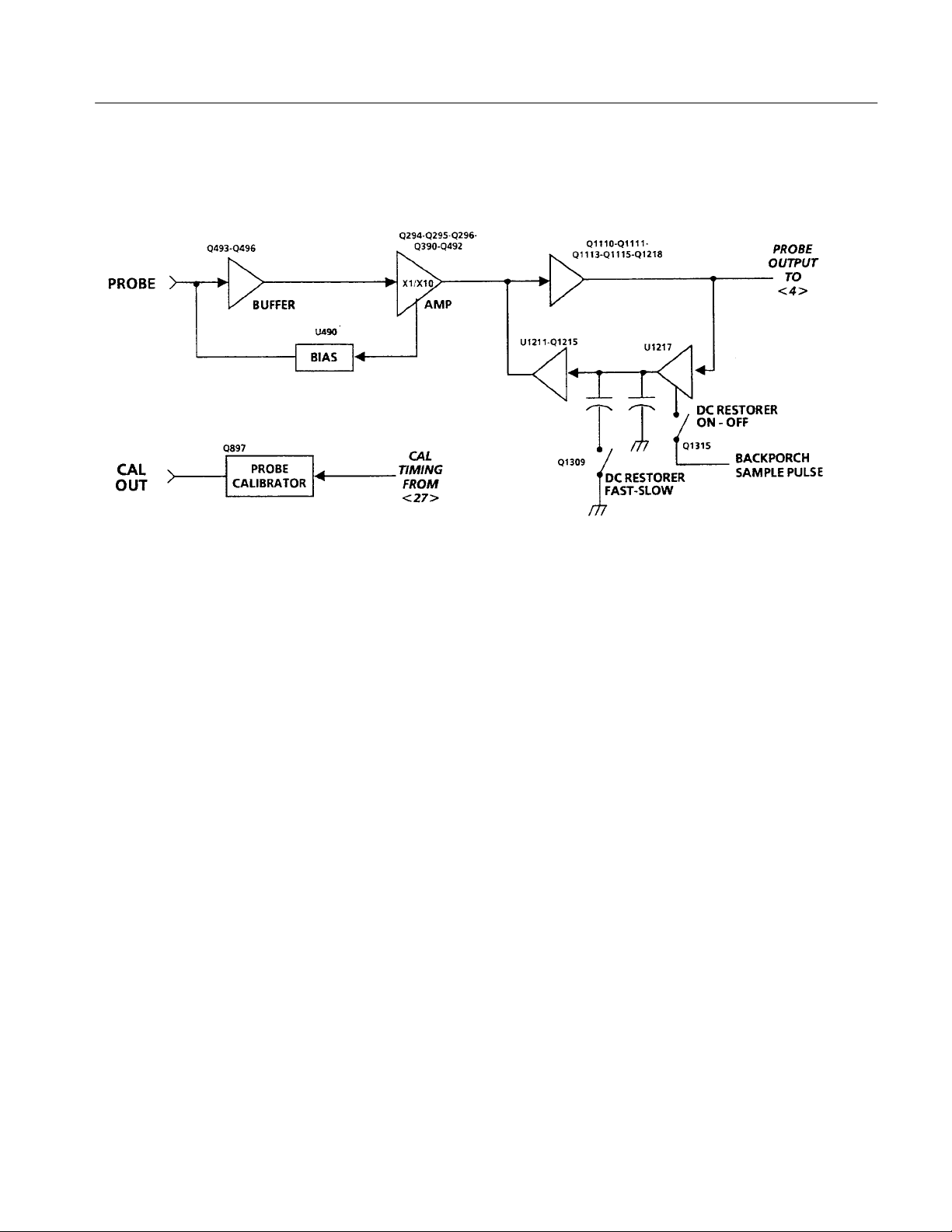
Diagram 3 Probe Input and DC Restorer
Theory of Operation
Overview
Circuit Theory
The 1780R-Series is equipped with a front-panel Probe Input, which allows it to
be used to make some measurements not normally possible with a waveform
monitor or vectorscope. The Probe Input is a high impedance input that can also
be used as another video input, when terminated with an in-line termination. The
Probe Input is configured to take either a X1 or X10 probe (Configure menu
selection) by switching in an internal 10X Amplifier when X10 is selected.
The Probe Output Amplifier has a DC Restorer identical to those used for the
video inputs. Clamping can be on the backporch or sync tip. The Probe DC
Restorer is controlled with the restorers on the four (CH A – CH B3) video
inputs; all restorers on, fast or slow, or sync tip or backporch clamp.
A front-panel Probe Calibrator Output is provided to set the probe gain and
compensation. Timing of the Probe Calibrator square wave is controlled by the
Microprocessor through the Vertical Calibrator and Filter Control in the vertical
control logic.
Probe Input Amp. The Probe Input Amplifier is a high input impedance non-inverting amplifier with a gain of 1.1 or 11, depending on instrument configuration. Bias for the AC-coupled amplifier is provided by a low-frequency feedback
loop.
Q493 and Q496 form a high impedance, unity gain voltage follower. C495 is the
AC input coupling capacitor. CR493 and R494 provide input overvoltage
protection. C494 bypasses R494 to improve frequency response. C493 adjusts
the probe input capacitance to 20 pF. R495 and R492 set the input resistance to
1 MW.
1780R-Series Service Manual
3–7
Page 85

Theory of Operation
The voltage follower drives a current-mode feedback amplifier consisting of
Q492, Q390, and Q294. The gain is set by the feedback network consisting of
R393, R396, R394, R295, and Q295. When the instrument is configured for X1
probe gain, Q295 is off and R393 and R396 set the amplifier gain to 1.1. In the
X10 gain setting, Q295 is saturated and the feedback signal from R393 is
shunted to ground through R394 and R295. This causes the gain of the amplifier
to increase to X11 when R295 is properly adjusted. Gain switching allows the
1780R-Series to work with either X1 or X10 probes.
The operating point of the Probe Input Amplifier is established by a feedback
loop consisting of U490, R491, C490, and R492. The loop tries to keep the
emitter of Q492 at 0 V. U490, R491, and C490 form a inverting integrator which
compares the voltage on Q492’s emitter to 0 V. If the emitter is not at 0 V, then
the charge on C490 will change, and the voltage on U490 pin 6 will move in a
direction opposite to the error at Q492’s emitter. This voltage is applied to the
amplifier input through R492, forcing Q492’s emitter back to 0 V. The feedback
loop compensates for offset variations in Q493 and Q492 and prevents output
DC level shifts when the gain is changed from X1 to X10.
Probe Calibrator. The Calibrator provides a 1 volt square wave at the front-panel
CAL OUT pin jack. The Cal Timing signal, that originates from the Calibrator
and Filter Control (Diagram 7), alternately saturates and turns off Q897. The
Calibrator Amplitude (R795) sets the cathode potential on VR796 (collector
voltage for Q897) to 5 volts. When Q897 is turned off, a voltage divider (R897,
R898, and R899) sets the Probe Cal Out to 1 volt. When Q897 is saturated, the
Probe Cal Out is at ground.
Probe Output Amp. The Probe Output Amplifier consists of a variable attenuator
and a X2 gain non-inverting amplifier, together providing a gain of 0.9. When
combined with the X1.1/X11.1 gain of the Probe Input Amplifier, an overall
probe system gain of X1/X10 results.
R1106, R1107, and R1108 form the attenuator. R1107 adjusts the overall probe
system gain. Q1111, Q1218, Q1113, and Q1115 form the amplifier. Feedback
resistors R1116 and R1218 set the gain of 2. C1222 varies the amplifier
frequency response and is used to adjust the overall probe system response.
DC Restorer. Either the backporch or sync tip level of the applied video can be
clamped to 0 volts by the DC Restorer circuit, which consists of U1217 and
U1211. U1217 is a gated transconductance amplifier that samples the filtered
output of the Probe Amplifier during either sync tip or backporch (depending on
the timing of the sample pulse at pin 5). R1122, C1221, L1220, and C1220 (at
the inverting input, pin 2 input of U1217) form a low-pass filter, with a notch at
the subcarrier frequency. U1217 drives C1216, which holds charge during the
active portion of the video line. When Q1309 is on, C1313 is in parallel with
C1216, and the DC Restorer response is slowed so that 60 Hz (50 Hz for 1781)
3–8
1780R-Series Service Manual
Page 86

Theory of Operation
hum is not attenuated. The DC Restorer is turned off by the absence of the
sample pulses at the sample input (pin 5) of U1217. Hold capacitors C1216 and
C1313 discharge to 0 volts through R1314, and the emitter of Q1215 stays at
0 volts.
Operational amplifier U1211 (along with C1212, C1211, R1112, and R1216) is
an active low-pass filter that stabilizes the characteristics of the DC Restorer
loop. Q1215 provides a low output impedance for the filter at higher frequencies.
1780R-Series Service Manual
3–9
Page 87

Theory of Operation
Diagram 4 Input & Reference Selection
3–10
Overview
The + and – Amplifiers select the appropriate input signal for display. The
+ Amplifier output goes to the + input of the Difference Amplifier, while the
– Amplifier output goes to the – input. The four video signals from the Input
Amplifiers are connected to 6-to-1 video switches, which consist of multiple
sections of transistor arrays. Resistive networks at the inputs attenuate the signal
and provide a means for channel frequency response matching. The B channel
input signals are connected to both + and – switches for differential display of
the A-B input signals. Probe video and the Waveform (CAL SIG) and Vector
(CAL OSC) Calibrators are also switched into the signal path here. Inserting the
calibrators this early in the Vertical circuit enables calibration of more circuitry.
Signals from Channel A, Channel B, + Amplifier, and External Reference are
selected through transistor follower switches for horizontal and vectorscope
references.
1780R-Series Service Manual
Page 88

Theory of Operation
Circuit Theory
Video Input Selection. Each video switch is an operational amplifier connected for
unity gain, and consists of six differential amplifier inputs. An input is selected
by biasing the appropriate differential pair with current from current sources
Q1427 and Q1438. This biasing current is steered to the appropriate differential
pair by applying a TTL high level to the resistor network at the differential input
current source transistor. Only one + Amplifier and one – Amplifier input can be
selected at a time.
Reference Switch. Input A, Input B, or the +Signal output can be selected for
Internal Reference or Reference Video by forward biasing the diodes at the
switching transistor (Q1524, Q1534, Q1529, or Q1341) collectors. Pulling the
cathode junction of the diodes up to +5 volts turns off the particular signal.
1780R-Series Service Manual
3–11
Page 89

Theory of Operation
Diagram 5 Difference Amplifier & Video Filters
3–12
Overview
The signal at the output of the Difference Amplifier is distributed to many
internal circuits. Seventy-five-ohm video is provided to the Auxiliary Output and
Picture Monitor BNC connectors. There is an additional current source to
provide bright-up for the selected line(s) on the Picture Monitor Output.
There are four filters that act on the applied video signal (luminance, low-pass,
chrominance, and differentiated step). Their outputs are selected by a saturated
transistor switch. Unfiltered video passes to the switch unaltered for full
bandwidth frequency response. Several other signals can be switched in for
display at this point. They are Alt Demod and Vector R-Y from the vectorscope,
cursor voltages from the Vertical Control Schematic, and the Auxiliary Video
Input.
1780R-Series Service Manual
Page 90

Theory of Operation
Only one signal is switched through the saturating transistor at a time, although
Flat, Luminance, and Chroma may be time multiplexed.
The luminance filter has a 1 MHz bandwidth and a transmission zero at the
subcarrier frequency. It has been optimized for best transient response. This filter
has performance identical to the luminance filter used in the Tektronix 1480 and
1485 Waveform Monitors.
The chrominance filter is a bandpass filter centered on the chrominance
subcarrier. It is a Lerner-type filter, exhibiting arithmetic symmetry and linear
phase across its bandwidth for excellent phase transient response.
The low-pass filter is an eighth order Bessel-type filter consisting of four second
order active sections.
The differentiated step filter is a high-pass filter that acts on the output of the
luminance filter. It is a differentiator, or slope detector. The signal from the
luminance filter has uniform luminance rise times, so that the differentiated step
filter can generate pulses mostly dependent on step amplitude.
Circuit Theory
The Auxiliary Input, when combined with the Auxiliary Output, provides a
means for connecting an external filter to the 1780R-Series. This is a 75 W input
with 1.5 dB gain to compensate for loss in the applied filter. Of course, AUX IN
can also be used as another input to the 1780R-Series.
Difference Amplifier. U935 is a high bandwidth operational amplifier connected as
a difference amplifier with a gain of 2. This is where the subtraction occurs for
the front-panel A-B1, B1-B2, or B2-B3 selections. U935 drives all of the internal
filter circuits. Q1032 is a current source that inserts an offset into the Pix Mon
video for an intensified display during line select operation. Q937 performs the
same function for the picture monitor display on the Vectorscope CRT.
Filters and Filter Switching. The emitters of all the switches are at 0 volts DC. All
of the switching transistors, except the selected filter switch, have –1.7 volts on
the base to keep them off. When a switch is off, the diode connected to the
switching transistor collector is biased on to provide a low impedance signal path
to ground. A TTL high at the base resistor network turns on the transistor to
provide a low impedance signal path from collector to emitter.
Luminance Filter . The filtered signal is picked off by transistors Q847 and Q939
for C/Y measurements and picture monitor display. The picture monitor display
also has the line select strobe added to it through Q937.
1780R-Series Service Manual
Low-Pass Filter. This filter is an eighth order Bessel-type filter with four second
order active sections using operational amplifiers in U1046. Bandwidth is about
300 kHz, and transient response is optimized by adjusting C951.
3–13
Page 91

Theory of Operation
Chrominance Filter. The chrominance filter is a Lerner-type filter, exhibiting
arithmetic symmetry and linear phase across its bandwidth. U827 amplifies the
filtered chrominance signal to drive both the Waveform Monitor and Vectorscope
circuits.
Differentiated Step Filter. U840A and B with associated circuitry form an active
low-pass filter. U840C, D, and E form an operational amplifier. C838 and R837
are connected as a differentiator or highpass filter.
Auxiliary Input. AUX IN is switched into the signal path by saturating Q922.
When not selected, Q1022 is on to maintain the 75 W input impedance.
3–14
1780R-Series Service Manual
Page 92
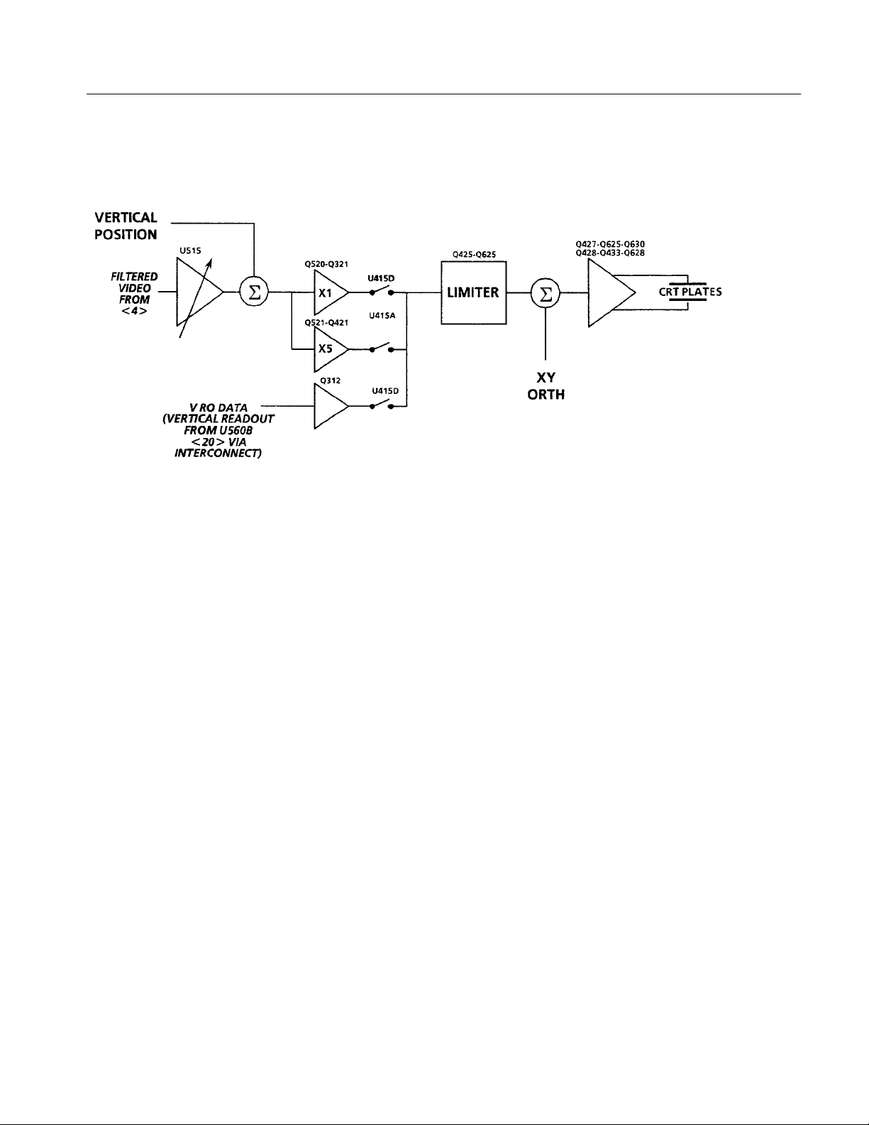
Diagram 6 Vertical Deflection
Theory of Operation
Overview
Circuit Theory
The current output of the filters passes through a common base amplifier which
drives a Gilbert multiplier (Variable Gain Amplifier). Output current from the
Variable Gain Amplifier drives inputs to two separate differential amplifiers (X1
and X5). The other side of the differential amplifiers is driven by the Vertical
Position voltage.
Vertical readout information from the Microprocessor is input through a third
differential amplifier. Only one of the three differential amplifiers (X1, X5, or
Readout) is operational at a given time. The output drives a Limiter and the
Deflection Amplifier to drive the CRT deflection plates. Limiting is required to
prevent the Deflection Amplifier from going into saturation or cut off.
Variable Gain. Q619 is a common base amplifier whose voltage output drives
U515 whose gain is controlled by the voltage between pins 8 and 10. U411B is a
–5 volt voltage source, and R513 is a longtailed current source. The voltage
between pins 8 and 10 of U515 is determined by manipulating the current
balance in Q514 through the voltage across R509. The Variable Gain Centering,
R514, is adjusted for a 450 mV calibrator signal amplitude in WFM+CAL mode
of operation. The Variable Gain Registration, R510, is adjusted so that there is
no output DC movement of a composite video signal when the variable
WAVEFORM GAIN control is varied.
The output current of the Gain Cell (U515) passes through cascode transistors
Q518 and Q519 to drive the X1/X5 Amplifier.
1780R-Series Service Manual
X1/X5 Amplifier. The X1/X5 Amplifier consists of two separate differential pairs
(Q520-Q321 and Q521-Q421), only one of which is on at any given time. The
emitter impedance of Q521-Q421 is 1/5 of the impedance of Q520-Q321, which
3–15
Page 93

Theory of Operation
gives them five times greater transconductance. Current from U415B is switched
to the appropriate differential pair by U415A and U415D. The differential pair
that is off has a high impedance so that it does not affect the other pair. The
second input to the differential pairs is connected to the vertical position voltage.
R526 sets the balance between the output currents to center the X5 gain at the
0 IRE (300 mV for PAL) graticule line.
Readout. A differential amplifier made up of Q310 and Q312 switches in the
vertical component of the waveform display readout. During readout time, bias
current from U415B is steered by U415D to this differential pair. Readout Size
(R215) and Readout Position (R309) adjustments are provided.
Limiter. The signal current from the X1, X5, or Readout Amplifier drives the
Deflection Amplifier, Q628 and Q427, through cascode transistors Q625 and
Q425. The voltage excursion at the base of these transistors is limited by
transistors Q423 and Q626. If the voltage at either emitter falls low enough to
turn on the transistor, the additional current for this node is shunted to the
opposite side. The limiter threshold level is adjusted so that the Deflection
Amplifier will not saturate or cut off.
Deflection Amplifier. Q628 and Q427 are a differential pair that generate the
current for controlling the deflection voltage. Q630 and Q428 convert the
Differential Amplifier input transistors into Unity Gain Amplifiers. Most of the
signal current flows through Q630 and Q428 so that the little power in the input
Q628 and Q427 does not change their base emitter voltage and distort the signal
at its extremes. The signal current flowing through Q635 and Q433 drives the
CRT deflection plates. R540 supplies a current from the horizontal sweep for
active correction of CRT orthogonality errors (misalignment of the vertical and
horizontal deflection plates).
3–16
1780R-Series Service Manual
Page 94

Diagram 7 Vertical Control Logic, Calibrator, & Cursors
Theory of Operation
Overview
Circuit Theory
1780R-Series Service Manual
The Microprocessor controls the vertical functions through three 8-bit latches.
These are all static logic levels. Dynamic switching, such as the Ch-A/Ch-B
Parade display, is achieved by state machines in logic arrays, and is timed by
sync from the Horizontal Timing circuit. Analog voltages, such as position and
gain, come from the Sample-and-Hold circuits on Schematic 12.
Input Selection. Input selection data (encoded into 8 bits) is latched in from the
data bus by U1516. Selection of inputs to the Differential Amplifier occurs in
U1415, a logic array, and the two latches at its output. Bits I1 through I4 contain
the + Amplifier switch information, while bits I5 through I7 contain the
– Amplifier information. The PAR MODE bit provides additional information to
U1415 (I8) when Parade mode is selected. Table 3–2 shows the coding of the
inputs. The table also shows the signal that is currently being used as the internal
reference source.
3–17
Page 95

Theory of Operation
perati
e
T able 3–2: Input Channel Selection Logic
Par
(U1415) (U1415)
O
ng Mod
Input(s)
I
1
I
2
I
3
I
4
I
5
I
6
I
7
Mode
I
8
Internal
Reference
SINGLE INPUT A 0 0 0 0 0 0 0 0 CH A
SINGLE INPUT B1 0 0 0 1 0 0 0 0 CH B1
SINGLE INPUT B2 0 0 1 0 0 0 0 0 CH B2
SINGLE INPUT B3 0 0 1 1 0 0 0 0 CH B3
SINGLE INPUT PROBE 0 1 1 1 0 0 0 0 PROBE
DIFFERENTIAL A B1 0 0 0 0 1 0 0 0 CH A
DIFFERENTIAL B1 B2 0 0 0 1 1 0 1 0 CH B1
DIFFERENTIAL B1 B3 0 0 0 1 1 1 0 0 CH B1
PARADE A + B1 1 0 0 0 0 0 0 1 CH A
PARADE A + PROBE 1 0 0 1 0 0 0 1 CH A
PARADE B1 + PROBE 1 0 1 0 0 0 0 1 CH B1
PARADE B1 + B2 + B3 1 1 1 1 0 0 0 1 CH B1
PARADE B1 B2 + B2 B3 0 0 0 1 1 1 1 1 CH B1
OVERLAY A + B1 1 0 0 0 0 0 0 0 CH A
OVERLAY A + PROBE 1 0 0 1 0 0 0 0 CH A
OVERLAY B1 + PROBE 1 0 1 0 0 0 0 0 CH B1
OVERLAY B1 + B2 + B3 1 1 1 1 0 0 0 0 CH B1
OVERLAY B1 + B2 1 1 0 0 0 0 0 0 CH B1
OVERLAY B1 + B3 1 1 0 1 0 0 0 0 CH B1
OVERLAY B2 + B3 1 1 1 0 0 0 0 0 CH B1
WFM + CAL A + CAL 0 0 0 0 0 0 1 0 CH A
WFM + CAL B1 + CAL 0 0 0 1 0 0 1 0 CH B1
WFM + CAL B2 + CAL 0 0 1 0 0 0 1 0 CH B2
WFM + CAL B3 + CAL 0 0 1 1 0 0 1 0 CH B3
WFM + CAL PROBE + CAL 0 1 1 1 0 0 1 0 PROBE
CALIBRATOR CAL SIG 0 1 0 1 0 0 1 0 GROUND
CALIBRA T OR OSC CAL OSC 0 1 0 1 0 1 0 0 GROUND
Decoders U1316 and U1523 convert the 3-bit logic array outputs to single active
high signals. When an input mode requires dynamic switching of inputs, such as
A/B Parade or B1-B2/B1-B3, the U1415 state machines cycle their outputs
through the appropriate sequence, timed by sync and the horizontal retrace pulse.
3–18
1780R-Series Service Manual
Page 96
Theory of Operation
DC Restorer and Reference Selection. Data for the reference and DC Restorer is
latched in by U1506. This latch controls input coupling and DC Restorer
operation along with the internal/external reference selection.
Filter Selection. The encoded 4 bits of filter selection data is latched in by U905.
U815 is a logic array, controlling filter selection and calibrator timing. U720 is a
3:8 decoder outputting the filter selection signals for Diagram 5. Four data bits
on Latch U905, F0 through F3, have all the filter selection data encoded in them.
See Table 3–3. Logic for multiple filter displays, such as Flat/Lum, is in a state
machine in U815.
T able 3–3: Filter Selection Logic
Filter(s) F
FLAT 0 0 0 0
LUMINANCE 0 0 1 0
CHROMINANCE 0 1 0 0
LOW-PASS 1 0 0 0
DIFF STEP 1 0 1 0
AUX VIDEO IN 1 1 0 0
AL T DEMOD 1 1 1 0
VECTOR R-Y 0 0 0 1
* The length of the horizontal sweep determines whether two or three filters are
displayed.
0
F
1
F
2
F
3
U815 has a divider circuit that generates the calibrator square wave, whose
frequency is 1/8th of the applied horizontal or vertical sync rate. The differential
output signal from pins 17 and 18 drives the Calibrator, U1019A.
Calibrator. The Calibrator signal is output from U1019A. It has R1119 for the
feedback resistance, with R1007 and R1008 forming the input resistance.
Calibrator upper and lower level voltages, from the Sample-and-Hold circuits on
Diagram 12, determine input currents thorough the input resistors (R1007 and
R1008). They are alternately switched (U1011C and D) by the Differential
Calibrator square wave timing signal from U815.
1780R-Series Service Manual
Vertical Position. Vertical position voltages, from the Sample-and-Hold circuits
on Diagram 12, are connected to a three-to-one switch, U505. U1105 selects
W VERT POS 1 as the main vertical position control voltage. The other two
voltages are used for the B2 and B3 position offsets in the B1/B2/B3 multiple
display modes.
3–19
Page 97

Theory of Operation
U1105 is a logic array that selects the timing rate (pin 16) for the logic on this
schematic. HSYNC or VSYNC is selected depending on whether the horizontal
sweep rate is at a line rate or field rate.
V oltage Cursors. U1019B is the Voltage Cursor Amplifier. Upper and lower
voltage levels are determined by the Microprocessor, and are stored by the
Sample-and-Hold circuits on Diagram 12. The Cursor Select control line from
the Readout Engine (Diagram 21) is converted to a bipolar signal in U1105.
Line Strobe Out. In line select operation, a TTL high pulse appears at the Line
Strobe Out rear-panel BNC connector during the selected line time. Jumper
J1103 can be moved to its other position to send the Field 1 pulse from the SCH
circuit instead of the line bright-up pulse.
3–20
1780R-Series Service Manual
Page 98

Diagram 8 Reference Sync Generation
Theory of Operation
Overview
Circuit Theory
Both Internal and Reference sync inputs are filtered by active low-pass filters.
The Internal Sync Separator is a descrete clamped operational amplifier circuit
that is clamped just above sync tip level to clip off active video.
The Reference Sync Separator is monolithic providing both composite sync and
AGC video outputs. Its AGC output is used to trigger the slow sweep circuits.
The Reference Sync Separator accommodates sound-in-syncs by replacing the H
sync pulses with a fixed 5 ms pulse.
A Sync Locked Oscillator outputs a burst of subcarrier rate sine wave that can be
adjusted to start between 70 and 400 ns after the leading edge of sync. A Mixer
compares this signal to the color burst, outputting a pulse when the 50% point of
sync corresponds to a negative zero crossing of subcarrier. The sync phase output
pulse is used to drive color framing logic.
Internal Sync Separator. The internal video is input through a 1.5 MHz active
low-pass filter made up of Q1251, R1248, R1249, C1247, and C1251. The
filtered video drives the Internal Sync Separator, which is a high gain inverting
operational amplifier and a feedback clamp. The clamp adjusts the DC level of
the operational amplifier so that video just above sync tip causes it to saturate
and clip off the video. Q1152 and U1159D form the operational amplifier with
1780R-Series Service Manual
3–21
Page 99

Theory of Operation
R1156 and R1253 setting the AC gain. CR1155, CR1254, U1159A, and C1254
form the feedback clamp. The clamp sets sync tip to +3 V at the operational
amplifier output (U1159 pin 1). U1159B and R1260 provide a constant current
discharge path for C1254 during sync time. The clamp voltage is varied by
adjusting the current flow through CR1254. U1159C amplifies and inverts the
separated sync producing a 5 volt, negative-going sync pulse at its collector (pin
14).
Reference Sync Separator. The selected reference video is input through a
1.5 MHz active low-pass filter made up of Q1475, Q1374, and associated
components. The filtered video drives U1483, a monolithic Sync Separator.
Negative-going composite sync is output on pin 5, which is an open collector
output allowing R1378 and CR1273 to pull-up and clamp the signal for a 0 to
+5.3 V output swing. When J1483 is set to the sound-in-sync (SIS) position,
U1483 replaces the sync time with a fixed, 5 s pulse. This provides proper
synchronization even if digital data such as sound-in-sync is present during
horizontal sync time.
Filtered Reference Video is inverted and scaled so that sync-to-blanking is
800 mV, and then is output as AGC video on pin 13. Q1380 buffers the signal
and outputs it to the Slow Sweep Triggering (Diagram 13). Q1483, R1480, and
R1481 limit the Sync Separator AGC range so that it does not output noise
bursts with no input video.
Sync Locked Oscillator. The Sync Locked Oscillator is locked to sync by a PLL
(Phase Locked Loop). U1060 is the phase detector/error amplifier which
compares the phase of the VCXO, U1065C, to one-shot U1270A’s output. The
140 ns pulse (100 ns for PAL) at the output of U1270A is box-car delayed. by
U1270B to provide a calibration adjustment, R1263, for the external reference
sync phase. (Box-car delay is accomplished by using two one-shots; one is
triggered and the other provides delay.) C1072 is adjusted to center the VCXO
(Voltage-Controlled Crystal Oscillator) operating point.
Reference Sync Phase. The Sync Locked Oscillator output is input to one port of
a Mixer, U1277. The Reference Video is multiplied by 2 by an inverting
amplifier (Q1471 and Q1472), filtered by a chroma bandpass filter (C1370 and
L1374), and input to the second port of the Mixer. The Mixer, U1277, is turned
on at burst time by saturated switch Q1389 that is keyed by the Burst Gate
output of the Sync Separator (U1483 pin 4). A differential current is output,
during burst time, from U1277 (pins 6 and 12). Its magnitude is determined by
the phase difference between the Reference Video burst and the output of the
Sync Locked Oscillator. This differential current flows in R1176, R1177, and
C1179 where it is filtered and converted to a voltage to drive a comparator,
U1179. The REF SCH ADJ (R1263 in the Sync Locked Oscillator) adjusts the
start time of the Sync Locked Oscillator so that the comparator outputs a positive
3–22
1780R-Series Service Manual
Page 100

Theory of Operation
pulse when the 50% sync point corresponds with a negative subcarrier zero
crossing ±80°. This positive-going output pulse drives the SCH color framing
logic on Diagram 14.
1780R-Series Service Manual
3–23
 Loading...