

Page 1

067-2431-xx
Deskew Fixtur
ZZZ
Instructions
Internal circui
between –1.5 and +4 volts, with a rise time of
40 ps. The fixture
ports of the oscilloscope.
Connectors on the fixture accept the coax
adapters and solder tips that are available for the
e
P7600 Series probes.
NOTE. You cannot deskew probes with coax
connectors to probes with solder tips; only
coax-to-coax or tip-to-tip probes can be
deskewed together.
CAUTION. The deskew fixture is ESD
sensitive. To avoid damaging the fixture,
only use it at an antistatic workstation and
observe proper ESD practices.
Standard Accessories
The following
deskew fixture:
try conditions the input signal to
is powered by one of the USB
accessories are included with the
Deskew Procedur
compensates for signal delays that occur between
probes due to dif
The oscilloscope deskew feature applies deskew
values after it
deskew values do not affect logic triggering.
Deskew has no af
formats.
e. The deskew function
ferent tips or cable lengths.
completes each acquisition. The
fect on XY and XYZ display
*P071302900*
071-3029-00
Deskew Fixture
The probe deskew fixture provides an edge
source to time-align (deskew) signals at the
inputs of P7600 Series probes. It allows you
to deskew the probes when you are using
P76CA-xxx probe adapters with coax cables or
the P76TA solder tip adapter with P7500 Series
TriMode Probe solder tips.
The edge signal input voltage is internally
adjustable to accommodate different logic levels,
and is provided by the oscilloscope FAST EDGE
output or by an external source. The edge signal
input voltage must be between –2 and +5 volts,
with a 1 ns or faster rise time.
Accessory
USB cable, A to B, 6 ft
SMA cable, male-to-male, 36 in
Adjustment tool 003-1890-xx
Instructions 071-3029-xx
Overview
For best performance, you should do the DC
Calibrati
Deskew procedure. Refer to your probe manual
for detail
Probe Calibration Procedure.
You should also check the calibration status of the
probes that you intend to use prior to performing
the deskew procedure. Use the procedure below.
Check the Calibration Status.
1. Select Probe Cal... from the Vertical menu.
2. Select the channel to which the probe is
If the te
problem; do not continue with the deskew
procedu
on procedure before performing the
ed instructions for performing the DC
attached and then check the Probe Status
readout:
Initialized. The probe has not been
ed on the selected channel; perform
calibrat
the DC probe calibration procedure.
Compensated. The probe has been
calibrated on the selected channel.
Fail. The probe has not been calibrated;
repeat the procedure.
st continues to fail, troubleshoot the
re.
Tektronix
part number
174-5194-xx
174-5631-xx
1. Connect the deskew fixture to a USB power
source. The power LED lights and the
solder tip retainer clips illuminate.
2. Connect the probes to the oscilloscope.
3. Connect th
connectors that match your probe. Leave
the 50 Ω ter
connectors.
NOTE. If y
solder tips, use the same solder tips with
the desk
measurements.
NOTE. You cannot deskew probes with coax
connect
coax-to-coax or tip-to-tip probes can be
deskewe
e probes to the fixture, using the
minations on any unused SMA
Connect the P76CA–292 or
P76CA–292C coax adapters to
the SMA connectors on the fixture.
Connect the P76CA–SM P coax
adapters to SMP-to-SMA adapters, and
then to the SMA connectors on the
fixture.
Attach the P76TA probe solder tip
adapter w
Probe solder tips beneath the
spring-l
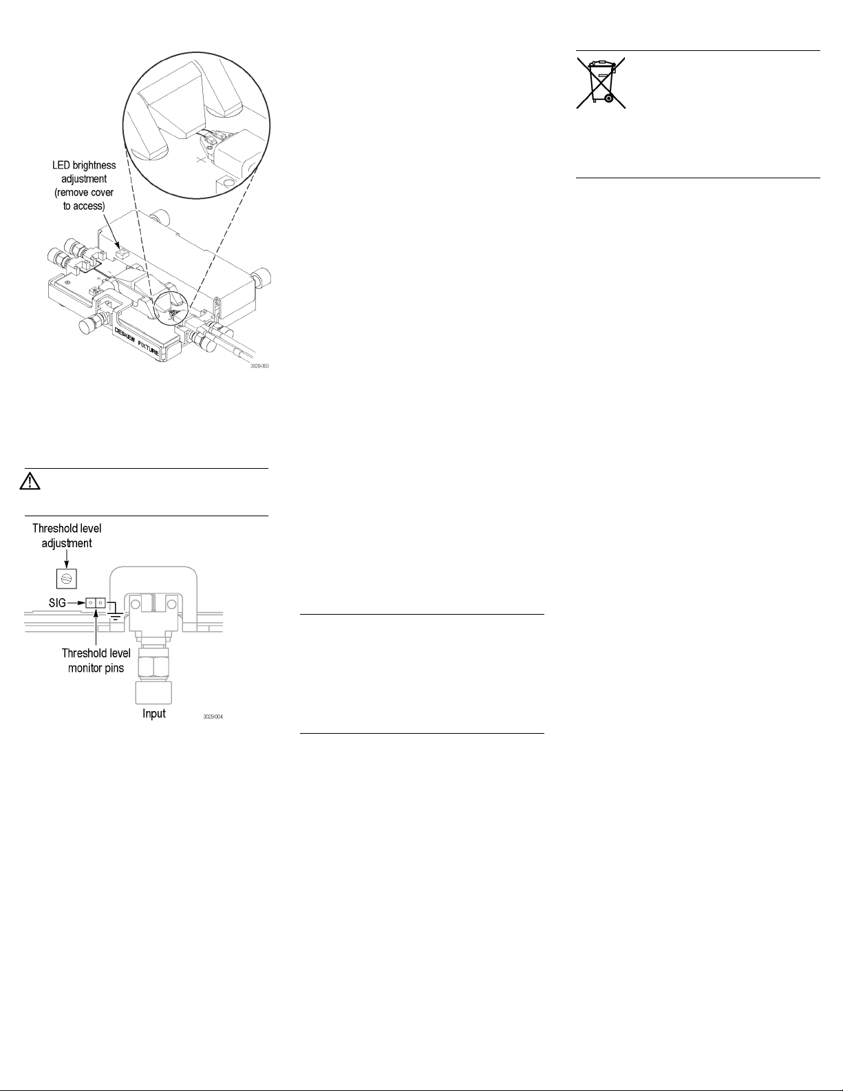
LEDs with adjustable brightness help
you align
fixture contacts. See figure below.
ith P7500 Series TriMode
oaded retainers on the fixture.
the probe tip leads to the
ou are deskewing probes with
ew fixture that you will use to take
ors to probes with solder tips; only
d together.
Page 2
4. Connect th
e edge signal input to the fixture.
Use either the FAST EDGE output on the
oscillosc
ope, or connect an external source.
The external signal source voltage must be
between –2
and+5volts,witha1nsor
faster rise time.
CAUTION. D
o not exceed the input voltage
limits of the fixture. Damage to the fixture
and probes
may result.
7. Select a referen
ce channel with which all
other channels will be deskewed. This is
typically Chann
el 1, but can vary depending
on your setup.
8. Select Deskew from the Vertical menu.
9. Select Channel 1 and set the Deskew to
0.0 s.
10. Display all channels to deskew, including
the reference c
hannel.
11. Set the Display Persistence to Infinite
Persistence mode.
12. Set the Record View Palette to Temperature
Grading.
13. Adjust the trigger level to get a stable
trigger.
14. Adjust the vertical SCALE, POSITION,
and OFFSET for each channel so that the
signals overlap and are centered on screen.
Make sure all channels being deskewed are
at the same volts/div setting. Deskew the
channels at the same level as your planned
signal measurement.
15. Adjust the horizontal POSITION so that
a triggered rising edge of the reference
channel is at center screen.
16. Adjust the horizontal SCALE so the
differences
in the channel delays are clearly
visible.
17. Adjust the horizontal POSITION again so
that the first rising edge of the reference
channel is at center screen.
18. Select Deskew from the Vertical menu.
19. Select one of
the channels to match to the
reference channel.
Equipment Recyc
complies with the European Union’s
requirements according to Directive
2002/96/EC on waste electrical and
electronic equipment (WEEE). For
more information about recycling
options, check
section of the Tektronix Web site
(www.tektronix.com).
ling. This product
the Support/Service
Contacting Tektronix
Web site: www.tektronix.com
Phone: 1-800-833-9200
Address: Tektronix, Inc.
Email:
Department or name (if known)
14200 SW Karl Braun Drive
P.O. Box 500
Beaverton, OR 97077 USA
techsupport@tektronix.com
Warranty Information
For warranty information, go to
www.tektronix.com/warranty.
5. Connect a DMM or oscilloscope to the
threshold level monitor pins.
6. Using an insulated tool, adjust the threshold
level on the fixture to the appropriate logic
level (for example, 1.4 V for TTL circuits).
NOTE. Do the n
ext step at a signal amplitude
within the same attenuator range (vertical scale)
as your plan
ned signal measurements. A ny
change to the vertical scale after the deskew is
complete ca
n change the attenuator setting and
give a slightly different signal path. This signal
path differ
ence can cause as high as 100 ps
variation in timing skew between channels.
20. Adjust the d
eskew time for that channel
so that its signal a ligns with that of the
reference c
hannel.
21. Repeat steps 19 and 20 for each additional
channel that you want to deskew.
opyright © Tektronix, Inc. A ll rights reserved. www.tektronix.com
C
 Loading...