

Page 1

Instructions
067-0484-02 and above
Deskew Fixture
071-7022-02
Warning
The servicing instructions are for use by qualified
personnel only. To avoid personal injury, do not
perform any servicing unless you are qualified to
do so. Refer to all safety summaries prior to performing service.
www.tektronix.com
*P071702202*
071702202
Page 2

Copyright © Tektronix, Inc. All rights reserved.
Tektronix products are covered by U.S. and foreign patents, issued and pending. Information in this publication supercedes
that in all previously published material. Specifications and price change privileges reserved.
Tektronix, Inc., P.O. Box 500, Beaverton, OR 97077
TEKTRONIX and TEK are registered tradem arks of Tektronix, Inc.
Page 3

Table of Contents
Mechanical Parts List
General Safety Summary iii...................................
Service Safety Summary v....................................
Contacting Tektronix vi.............................................
Deskew and Gain Cal Fixture Instructions 1............................
Overview 1.......................................................
Specifications 2...................................................
Powering the Deskew Fixture for Skew Adjust 2.........................
Connecting Probes to the Deskew Fixture 3.............................
Load balancing when deskewing a differential probe with a single-ended
probe 10......................................................
Using the Deskew Fixture to deskew channels 12.........................
Connecting to the Gain Cal Fixture 14..................................
Using the Deskew Fixture to Gain Cal 18................................
Mechanical Parts Lists 21............................................
Deskew Fixture Instructions
i
Page 4

Table of Contents
ii
Deskew Fixture Instructions
Page 5

General Safety Summary
Review the following safety precautions to avoid injury and prevent damage to
this product or any products connected to it. To avoid potential hazards, use this
product only as specified.
Only qualified personnel should perform service procedures.
While using this product, you may need to access other parts of the system. Read
the General Safety Summary in other system manuals for warnings and cautions
related to operating the system.
Observe All Terminal Ratings. To avoid fire or shock hazard, observe all ratings
and markings on the product. Consult the product manual for further ratings
information before making connections to the product.
Use Proper Fuse. Use only the fuse type and rating specified for this product.
Avoid Exposed Circuitry. Do not touch exposed connections and components
when power is present.
Do Not Operate With Suspected Failures. If you suspect there is damage to this
product, have it inspected by qualified service personnel.
Do Not Operate in Wet/Damp Conditions.
Symbols and Terms
Do Not Operate in an Explosive Atmosphere.
Keep Product Surfaces Clean and Dry.
Terms in this Manual. These terms may appear in this manual:
WARNING. Warning statements identify conditions or practices that could result
in injury or loss of life.
CAUTION. Caution statements identify conditions or practices that could result in
damage to this product or other property.
Symbols on the Product. The following symbols may appear on the product:
CAUTION
Refer to Manual
Protective Ground
(Earth) Terminal
Deskew Fixture Instructions
iii
Page 6

General Safety Summary
iv
Deskew Fixture Instructions
Page 7

Service Safety Summary
Only qualified personnel should perform service procedures. Read this Service
Safety Summary and the General Safety Summary before performing any service
procedures.
Do Not Service Alone. Do not perform internal service or adjustments of this
product unless another person capable of rendering first aid and resuscitation is
present.
Disconnect Power. To avoid electric shock, switch off the instrument power, then
disconnect the power cord from the mains power.
Use Care When Servicing With Power On. Dangerous voltages or currents may
exist in this product. Disconnect power, remove battery (if applicable), and
disconnect test leads before removing protective panels, soldering, or replacing
components.
To avoid electric shock, do not touch exposed connections.
Deskew Fixture Instructions
v
Page 8

Service Safety Summary
Contacting Tektronix
Phone 1-800-833-9200*
Address Tektronix, Inc.
Department or name (if known)
14200 SW Karl Braun Drive
P.O. Box 500
Beaverton, OR 97077
USA
Web site www.tektronix.com
Sales support 1-800-833-9200, select option 1*
Service support 1-800-833-9200, select option 2*
Technical support www.tektronix.com/support
1-800-833-9200, select option 3*
6:00 a.m. -- 5:00 p.m. Pacific Standard Time
* This phone number is toll free in North America. After office hours, please leave a voice mail
message.
Outside North America, contact a Tektronix sales office or distributor; see th e Tektronix web
site for a list of offices.
vi
Deskew Fixture Instructions
Page 9

Deskew and Gain Cal Fixture Instructions
Cable retainer (4)
Springs (3)
Guide posts (3 pairs)
Probe holders (2)
USB Port
GAIN CAL SIG
connector
Overview
Figure 1: Overview of Deskew Fixture
This fixture provides an edge source to time align (deskew) and to optimize
oscilloscope gain and offset accuracy at the probe tip.
The Deskew Fixture accommodates several T ektronix probes. It has components
that aid in the alignment of probes, such as cable retainers, stainless steel
springs, guide posts and square pins. The probes are held in place allowing
hands-free operation without requiring a probe arm.
CAUTION. Static discharge can damage any semiconductor component on this
deskew fixture.
Adhere to the following precautions to avoid damaging internal modules and
their components due to electrostatic discharge (ESD).
1. Transport and store the deskew fixture in static protected containers.
Deskew Fixture Instructions
1
Page 10

Deskew and Gain Cal Fixture Instructions
2. Discharge the static voltage from your body by wearing a grounded antistatic
wrist strap while handling or servicing the deskew fixture. Do service only at
a static-free work station.
Specifications
H USB load, ᇓ60 mA typical, from the 5 V supply.
H Deskew Fixture output voltage, V
H Deskew Fixture Risetime and frequency, <600 ps, p =10MHz.
H Gain Cal input and output is less than
Table 1: Certifications and compliances
Category Standards or description
EC Declaration of Conformity -EMC
Australia/New Zealand Declaration of Conformity -- EMC
Meets intent of Directive 89/336/EEC for Electromagnetic Compatibility. Compliance was
demonstrated to the following specifications as listed in the Official Journal of the European Union:
EN 61326 1,2,3 EMC requirements for Class A electrical equipment for measurement, control
and laboratory use1
EN 61000--3--2 4 AC power line harmonic emissions
1 Radiated emissions may exceed the levels specified in EN 61326 when this instrument is
connected to a test object.
2 Exposed circuitry on the Deskew Fixture may be damaged by electrostatic discharge. IEC
61000--4--2 is not applicable to the circuit board area.
3 Immunity performance is dependent on the device supplying power via the USB connection.
4 Compliance to EN 61000--3--2 is dependent on the device supplying power via the USB
connection. Compliance is assured when powered by a TDS6000 or TDS7000 series instrument.
Complies with EMC provision of Radiocommunications Act per the following standard(s):
AS/NZS 2064.1/2 Class A limits for Industrial, Scientific, and Medical Equipment: 1992
ᇓ1V, Vohᇓ2V.
ol
±10 V
Powering the Deskew Fixture for Skew Adjust
The Deskew Fixture is powered from a USB port. Using a USB cable (supplied
with the fixture) you can connect the fixture to the USB port on the rear panel of
the oscilloscope or to a USB port on the Tektronix recommended USB keyboard.
You can use an external USB hub or PC.
Connect the Deskew Fixture to a USB power source.
2
Deskew Fixture Instructions
Page 11

Connecting Probes to the Deskew Fixture
WARNING. To avoid personal injury, use care while connecting probe tips to the
square pins on the fixture. The ends of the square pins are sharp.
The Deskew Fixture can be used with several different types of probes, and it
accommodates up to six Tektronix probes individually or in combination, (for
example, four differential probes with up to two single-ended probes).
Table 2 refers to diagrams that show how to attach a Tektronix probe to the
fixture. Refer to the symbols screened on the fixture to establish the correct
polarity.
Table 2: Probe deskew connections
Probe See figures
P6246, P6247, P6248,
P6330, P7330
Deskew and Gain Cal Fixture Instructions
2, 3, 6
P6246, P6247,
P6248, P6330,
P7330
P6249 4, 5, 6, 7, 8, 9, 10, 11
P7240 4, 5, 6, 7, 8, 9, 10, 11
P7260 6, 7, 8, 9, 11
NOTE. Be sure that the deskew fixture’s pins are straight before use. Take care
not to bend the pins.
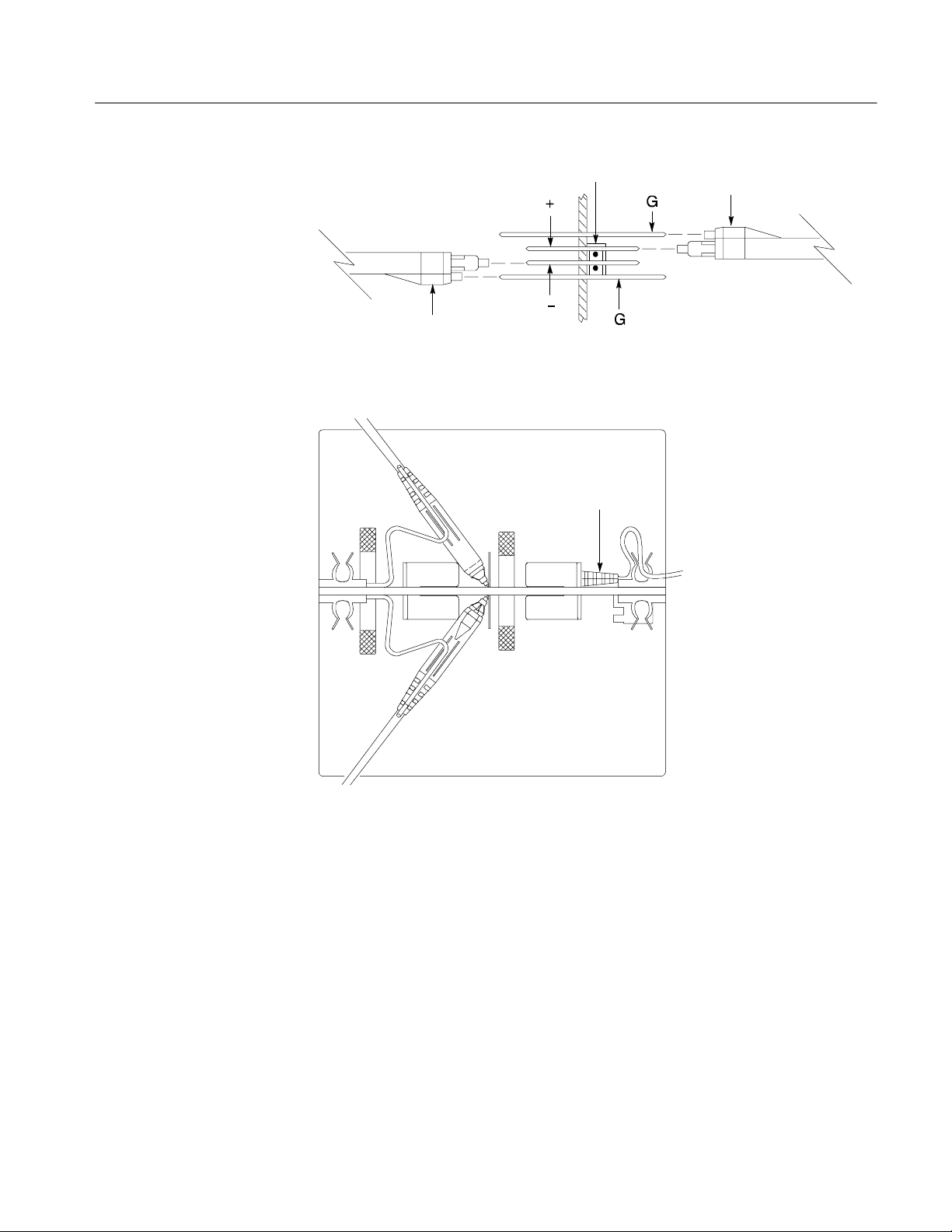
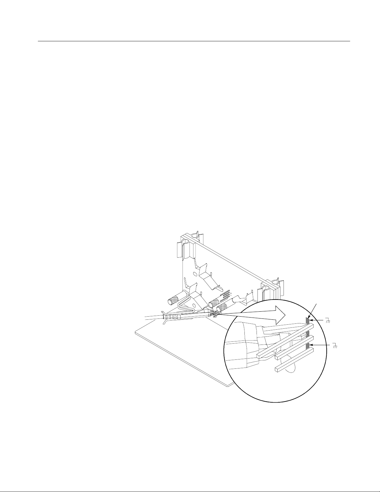
Use this procedure to deskew the P6246, P6247, P6248, P6330, and P7330
differential probes: If single-ended probes are required, go to the next section.
1. Insert the probe cable into the cable retainer.
2. Insert the probe body flush to the board between the adjacent spring and
guide post. See Figure 2 on page 4.
3. Slide the probe to allow both probe tips to contact the underside of the
SKEW ADJUST positive and negative square pins (middle two pins).
NOTE. Check the markings on the probe body to ensure the positive tip is
contacting the positive square pin on the fixture. You can deskew up to four
probes of this type with this fixture, two on each side of the board.
Deskew Fixture Instructions
3
Page 12

Deskew and Gain Cal Fixture Instructions
4. All probe tips should contact the SKEW ADJUST pins at the center of the
probe tips. See Figure 3 on page 5.
5. Set the probe atten switch to 1X position.
6. You can install up to four differential probes using both sides of the Deskew
Fixture. You can also install up to two single-ended probes.
7. Proceed to Using the Deskew Fixture to deskew channels, page 12.
Cable retainer
Springs
Ground
Guide posts
Ground
Figure 2: P6246, P6247, P6248, P6330 or P7330 fixture connections
4
Deskew Fixture Instructions
Page 13

Springs
Guide posts
Deskew and Gain Cal Fixture Instructions
Cable retainer
Ground
Ground
P6249, P7240 without tips
Figure 3: P6246, P6247, P6248, P6330, or P7330 fixture connections
Use this procedure to deskew the P6249 and P7240 single-ended probes without
Tektronix probe tips: If single-ended probes with tips are required go to the next
section.
1. Remove any probe tips from the probe.
2. Slide the probe over the top of the SKEW ADJUST ground and positive
pins. Be sure the probe is perpendicular to the Deskew Fixture. See Figures 4
and 5 on page 6. Repeat this step to add a probe to the other side of the
fixture.
3. Proceed to Using the Deskew Fixture to deskew channels, page 12.
Deskew Fixture Instructions
5
Page 14

Deskew and Gain Cal Fixture Instructions
Ground
Cable retainer
Springs
Ground
Guide posts
P6249, P7240, P7260 with
tips
Figure 4: P6249 or P7240 without tips
Deskewed probe
Deskewed probe
Figure 5: P6249 or P7240 each side of the fixture, without tips
Use this procedure to deskew P7260 single-ended probe. To deskew P6249 and
P7240 single-ended probes install the Tektronix probe tips:
1. Install the guide posts and probe holders to the SKEW ADJUST probe
holder position. See Figure 6 on page 8.
2. Secure the probe holders to the deskew fixture by installing the guide posts
through the probe holders and into the mounting hole.
3. Slide probe(s) into the probe holder(s) and tighten both guide posts.
6
Deskew Fixture Instructions
Page 15

Deskew and Gain Cal Fixture Instructions
4. Position the probe tips to the solder pad locations with the appropriate
polarity. See Figures 7 and 8 on page 9.
5. Firmly slide the probes forward until the probe tips make contact with the
SKEW ADJUST solder pads.
6. Perform the following procedure to provide probe tip contact pressure with
the SKEW ADJUST solder pads: See Figure 9 on page 10.
a. Pull back lightly on the probe holder assembly.
b. While holding the probe holder assembly back, slide the probe forward
until the probe tips stick into the solder pads.
c. Now carefully release the probe holder assembly. This will maintain
contact pressure.
d. Perform substeps a through c for deskewing a second probe.
See Figure 8 on page 9.
7. Proceed to Using the Deskew Fixture to deskew channels, page 12.
Deskew Fixture Instructions
7
Page 16

Deskew and Gain Cal Fixture Instructions
SKEW ADJUST
probe holder
postion
SKEW ADJUST
postion
GAIN CAL
postion
GAIN CAL
probe holder
postion
Figure 6: Alternate locations for guide posts and probe holders
8
Deskew Fixture Instructions
Page 17

Deskew and Gain Cal Fixture Instructions
Solder pads
G
G
Figure 7: P6249, P7240 or P7260 with tips
P7260
P7260
Deskew Fixture Instructions
Figure 8: P6249, P7240 or P7260 on each side of the fixture, with tips
9
Page 18

Deskew and Gain Cal Fixture Instructions
Step 1 Pull probe
holder back
Step 2 Push
probe forward
Figure 9: Probe tip contact loading
Load balancing when deskewing a differential probe with a single-ended probe
When deskewing a differential probe with a single-ended probe and to ensure
accurate deskewing, an identical single ended probe must be installed onto the
deskew pin of opposite polarity to balance the load of the single probe.
1. Install the single-ended probe (load balance probe) to the vacant pins. See
Figures 10 and 11 on page 11.
2. The load balance probe does not have to be connected to any test equipment.
10
Deskew Fixture Instructions
Page 19
Deskew and Gain Cal Fixture Instructions
Differential probe
Load balance probe
Deskewed probe
Figure 10: P6249 and P7240 load balance detail without tips
Load balance probe
Differential probe
Deskewed probe
Figure 11: P6249, P7240 or P7260 load balance detail with tips
Deskew Fixture Instructions
11
Page 20

Deskew and Gain Cal Fixture Instructions
Using the Deskew Fixture to deskew channels
You can adjust a relative time delay for each channel. This lets you align the
signals to compensate for signals that can come in from cables of differing
lengths. The oscilloscope’s deskew feature applies deskew values after it
completes each acquisition; therefore, the deskew values do not affect logic
triggering. Also, deskew has no affect on XY and XYZ display formats.
This procedure requires the user to select a common reference channel which all
other channels will be deskewed. This is typically Channel 1, but can vary
depending on the user’s setup.
For best results warm up the oscilloscope for 20 minutes before performing these
functions.
1. Connect the probes to the oscilloscope.
When the probes are inserted properly with both tips contacting the correct pins,
you will see the following approximate squarewave amplitude: 1500 mV for
differential probes; 750 mV for single-ended probes. If you do not see this
approximate amplitude, remove the probe and reinsert it or adjust it until the
approximate amplitude is achieved. Then, continue with the deskew process.
2. Touch the Vertical menu to display the Deskew menu.
3. Select Channel 1 and set the Deskew to 0.0s.
4. Display all channels that you want to deskew, including the reference
channel.
5. Push the AUTOSET button on the oscilloscope.
6. From the Horiz/Acq menu, select Horizontal/Acquisition Setup, select
Acquisition tab, select Average and # of Wfms 16. Adjust trigger level to
get a stable trigger.
7. Adjust the vertical SCALE and POSITION (with active probes adjusting
offset can be required) for each channel so that the signals overlap and are
centered on screen. It’s advised to make sure all channels being deskewed are
at the same Volts/div setting. See Figure 12 on page 13.
8. Adjust the horizontal POSITION so that a triggered rising edge of the
reference channel is at center screen.
9. Adjust the horizontal SCALE so that the differences in the channel delays
are clearly visible.
10. Adjust the horizontal POSITION again so that the reference channel’s first
rising edge is at center screen.
12
Deskew Fixture Instructions
Page 21

Deskew and Gain Cal Fixture Instructions
11. Touch the V ertical button menu to display the Vertical Setup menu control
window.
12. Touch the Probe Deskew button to display the channel-deskew control
window.
13. Select one of the slower channels.
NOTE. Do the next step at a signal amplitude within the same attenuator range
(vertical scale) as your planned signal measurements. Any change to the vertical
scale after the deskew is complete can introduce a new attenuation level. A
change in the attenuator setting will give a slightly different signal path. This
different path can cause as high as 200 ps variation in timing accuracy between
channels.
14. Adjust the deskew time for that channel so that its signal aligns with that of
the reference channel.
15. Repeat steps 11 and 12 for each additional channel that you want to deskew.
Channel 1
Channel 2
Figure 12: Centering waveforms on the screen
End of procedure
Deskew Fixture Instructions
13
Page 22
Deskew and Gain Cal Fixture Instructions
Connecting to the Gain Cal Fixture
Follow these steps to connect the probes and oscilloscope to the fixture.
1. Perform Signal Path Compensation (SPC) before you connect the probes:
a. Touch the Utilities button to display the Instrument Calibration menu.
b. Touch the Instrument Calibration menu to display the Calibration
Instructions menu.
c. Touch Calibrate to perform the Signal Path Compensation.
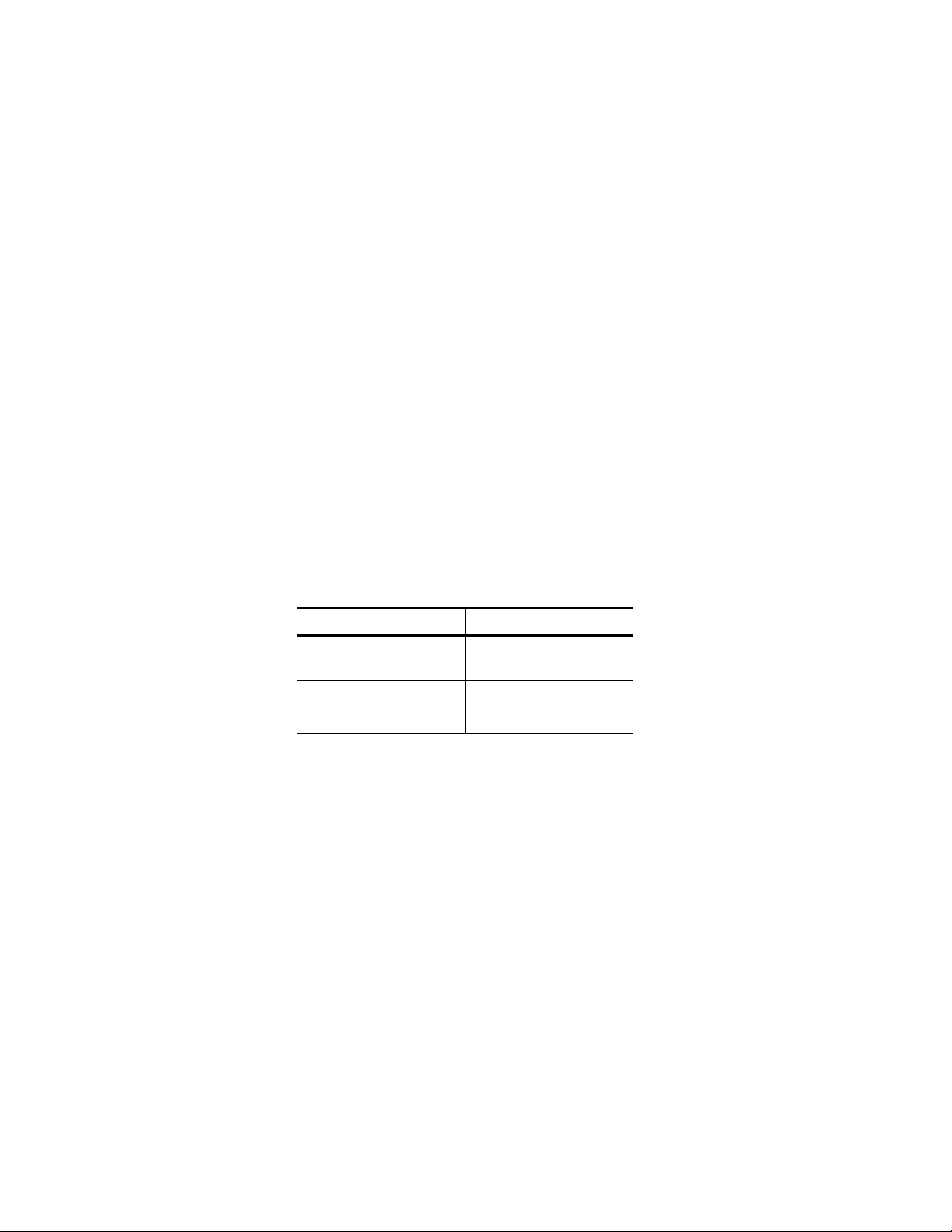
2. Connect the oscilloscope PROBE COMPENSATION (PROBE CALIBRA-
TION for the TDS6000B) output to a BNC cable (Tektronix part number
012-0208-00). Connect the remaining end of the BNC cable to the GAIN
CAL SIG connector located on the deskew board.
3. Move the guide posts to the GAIN CAL position. See Figure 6 on page 8.
4. Use the probe holders for P6249, P7240 and P7260 with probe tips installed.
Table 3: Probe gain cal connections
Probe See figures
P6246, P6247, P6248,
P6330, P7330
P6249, P7240 8, 14, 15
P7260 8, 15
13
14
Deskew Fixture Instructions
Page 23
Deskew and Gain Cal Fixture Instructions
P6246, P6247, P6248,
P6330, P7330
Use this procedure to Gain Cal the P6246, P6247, P6248, P6330, and P7330
probes:
1. Insert the probe cable into the cable retainer.
2. Insert the probe body flush to the board between the adjacent spring and
guide post. See Figure 13 on page 15.
3. Slide the probe to allow the probe tips to contact the underside of the
fixture’s signal and ground square pins.
4. Repeat steps 1 through 3 to calibrate a second probe at the same time, one on
each side of the fixture.
5. Proceed to the Using the Deskew Fixture to Gain Cal on page 18.
Cable retainers
Spring
Figure 13: P6246, P6247, P6248, P6330 or P7330 fixture connections
Deskew Fixture Instructions
15
Page 24
Deskew and Gain Cal Fixture Instructions
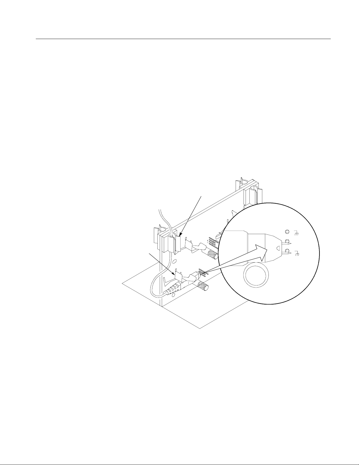
P6249, P7240 without tips
Use this procedure to Gain Cal the P6249 and P7240 probes without Tektronix
probe tips:
1. Remove any probe tips from the probe.
2. Slide the probe over the top of the ground and middle GAIN CAL pins. Be
sure the probe is perpendicular to the fixture. See Figure 14.
3. Proceed to the Using the Deskew Fixture to Gain Cal on page 18.
P6249, P7240, P7260 with
16
tips
Figure 14: P6249 or P7240 without tips
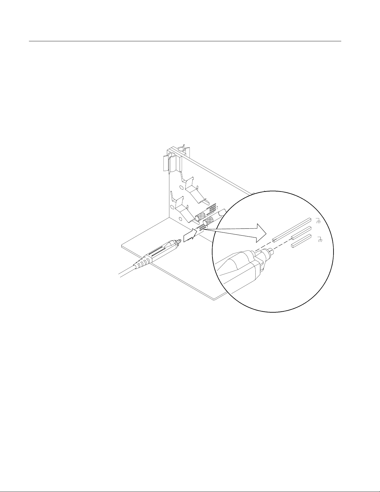
Use this procedure to Gain Cal P7260 single-ended probe. To Gain Cal P6249
and P7240 single-ended probes install the Tektronix probe tips:
1. Install the guide posts and probe holders to the GAIN CAL probe holderposition. See Figure 6 on page 8.
2. Secure the probe holders to the GAIN CAL by installing the guide posts
through the probe holders and into the mounting hole.
3. Slide probe(s) into the probe holder(s) and tighten both guide posts.
Deskew Fixture Instructions
Page 25
Deskew and Gain Cal Fixture Instructions
4. Position the probe tips to the solder pad locations with the appropriate
polarity. See Figure 15 on page 17.
5. Slide the probe forward until the probe tips make contact with the GAIN
CAL solder pads.
6. Perform the following procedure to provide probe tip contact pressure with
the GAIN CAL solder pads: See Figure 9 on page 10.
a. Pull back lightly on the probe holder assembly.
b. While holding the probe holder assembly back, slide the probe forward
until the probe tips stick into the GAIN CAL solder pads.
c. Now carefully release the probe holder assembly. This will maintain
contact pressure.
7. Perform steps 1 through 6 to calibrate a second probe at the same time. See
Figure 8 on page 9.
8. Proceed to the Using the Deskew Fixture to Gain Cal on page 18.
Deskew Fixture Instructions
Solder pads
Figure 15: P6249, P7240 or P7260 with tips
17
Page 26

Deskew and Gain Cal Fixture Instructions
Differential and single
ended probe Gain Cal
It is a possible to perform a Gain Cal using a differential and a single ended
probe at the same time.
1. Remove the guide posts from the GAIN CAL position.
2. Substitute the male guide post with a 6-32 screw (not supplied).
3. Install the 6-32 screw on one side of the board and the female guide post
with holder on the other side.
4. The side with the 6-32 screw will allow you to gain cal the differential
probe.
5. Proceed to the Using the Deskew Fixture to Gain Cal on page 18.
Using the Deskew Fixture to Gain Cal
Prior to probe gain calibration the oscilloscope must have had a 20 minute warm
up and completed a signal path calibration (SPC) procedure. See page 14.
NOTE. Probes with an attenuation factor of greater than 20X cannot be
compensated. Probes with >2% gain errors or >50 mV offset errors cannot be
compensated.
Optimize gain and offset
accuracy
NOTE. The USB cable does not need to be connected. GAIN CAL does not
require external power.
Perform the following procedure to optimize gain and offset accuracy:
1. Connect probe to the oscilloscope.
2. Connect probe to the fixture. See Table 3 on page 14 and Probe gain cal
connections on page 14.
3. From the tool bar, touch the Vertical button to display the oscilloscope
Vertical Setup control window.
4. Touch the Probe Cal button to display the vertical Probe Cal control
window.
5. Select the oscilloscope channel to which the probe is attached.
6. Touch Clear Probecal to erase any previous calibration data.
18
Deskew Fixture Instructions
Page 27

Deskew and Gain Cal Fixture Instructions
7. Touch the Calibrate Probe button.
8. When the routine is finished, remove the connections from the deskew
fixture.
Check the calibration
status
Perform the following procedure to check calibration status:
1. From the tool bar, touch the Vertical button to display the oscilloscope
Vertical setup control window.
2. Touch the Probe Cal button to display the vertical Probe Cal control
window.
3. Select the oscilloscope channel to which the probe is attached.
4. Check the Probe Status readout:
H Initialized: indicates that the probe has not been calibrated on the
selected channel.
H Pass: indicates that the probe has been calibrated on the selected channel.
H Fail: indicates the probe has not been calibrated, repeat gain cal
procedures.
NOTE. Probes without a TekProbe interface cannot be calibrated.
5. Touch the Help button to access the online assistance.
Deskew Fixture Instructions
End of procedure
19
Page 28

Deskew and Gain Cal Fixture Instructions
20
Deskew Fixture Instructions
Page 29

Mechanical Parts List
CAUTION. The following is for use only by qualified service personnel. Refer to
all Safety Summaries before performing any service.
This section contains a list of the replaceable modules for the Deskew Fixture.
Use this list to identify and order replacement parts.
Abbreviations
Mfr. Code to Manufacturer
Cross Index
Abbreviations conform to American National Standard ANSI Y1.1--1972.
The following table cross indexes codes, names, and addresses of manufacturers
or vendors of components listed in the parts list.
Manufacturers cross index
Mfr.
code
00779 TYCO ELECTRONICS CORP CUSTOMER SERVICE DEPT
06915 RICHCO 5825 N TRIPP AVE
0KB01 STAUFFER SUPPLY CO 810 SE SHERMAN PORTLAND, OR 97214--4657
0KB05 NORTH STAR NAMEPLATE INC METAL PRODUCTS
2K262 BOYD CORPORATION 6136 NE 87TH AVENUE PORTLAND, OR 97220
6D224 FCI USA INC I/O & CABLE DIVISION
80009 TEKTRONIX INC 14150 SW KARL BRAUN DR
TK0588 UNIVERSAL PRECISION PRODUCT 1775 NW CORNELIUS PASS RD HILLSBORO, OR 97124
TK0AT AMP, INC 7--15--14 ROPPONGI
TK1326 NORTHWEST FOURSLIDE INC 13945 SW GALBREATH DR SHERWOOD, OR 97140
TK2548 XEROX CORPORATION 7431 NE EVERGREEN PARKWAY, SUITE 130 HILLSBORO, OR 97124
Manufacturer Address City, state, zip code
P.O. BOX 3608
P.O. BOX 804238
5750 NE MOORE COURT
5700 WARLAND DRIVE
PO BOX 500
MINATO-- KU
HARRISBURG, PA 17105--3608
CHICAGO, IL 60646
HILLSBORO, OR 97124--6474
CYPRESS, CA 90630
BEAVERTON, OR 97077--0001
TOKYO JAPAN,
Deskew Fixture Instructions
21
Page 30

Mechanicl Parts List
11
10
9
12
1
7
Figure 16: Deskew Fixture
8
5
6
3
2
4
22
Deskew Fixture Instructions
Page 31

Mechanicl Parts List
Replaceable Parts List
Fig. &
index
number
16--1 129--1557--00 3 POST:GUIDE,DESKEW,FEMALE,SMX.IGS,STAINLESS STEEL TK0588 129-- 1557-- 00
--2 174--4401--00 1 CABLE ASSY,I/O:USB, 26 AWG, 3.281 FT, A TO B, MALE 6D224 72380--B100BC
--3 432--0176--00 1 BASE ASSEMBLY:W/LEXAN LABEL,3.0 X 5.50 X 0.175 0KB05 432-- 0176-- 00
--4 348--0430--00 4 FOOT:BUMPER,PLASTIC:POLYURETHANE,BLACK 2K262 ORDER BY
--5 211--1050-- 00 2 SCREW,MACH INE:6-- 32 X 0.312 L,PNH,STL CAD PLT,T15 0KB01 OBD
--6 131--6562--00 1 CONN:PC B,USB SERIES B,FEMALE,RTANG TK0AT 787780-- 2
--7 071--7022--XX 1 MANUAL,T ECH:INSTRUCTION, DESKEW F IXTURE TK2548 071--7022--XX
--8 131--3721--00 1 CONN, RF JACK:BNC SERIES B, FEMALE 00779 227699--2
--9 129--1558--00 3 POST:GUIDE,DESKEW,MALE,SMXGS,STAINLESS STEEL TK0588 129--1558--00
--10 214--5005--00 3 SPRING:DESKEW,SMX IGS,0.008 SSTL FULL HARD TK1326 214--5005--00
--11 343--0401--00 4 RETAINER,CABLE:PLASTIC 06915 KKU--4RT
--12 352--1099--00 2 HOLDER, PROBE: DESKEW P6249, P7240,W/tips 80009 352-- 1099-- 00
Tektronix
part number
Serial no.
effective
Serial no.
discont’d
Qty Name & description
Deskew Fixture
Mfr.
code
Mfr. part number
DESCRIPTION
Deskew Fixture Instructions
23
Page 32

Mechanicl Parts List
24
Deskew Fixture Instructions
 Loading...