

Page 1

Instructions
065-0702-XX, 065-0717-XX, 050-3674-XX
LCD/Touch Screen Replacement Kit
TDS5000B Series Oscilloscopes
075-0837-01
Warning
The servicing instructions are for use by qualified
personnel only. To avoid personal injury, do not
perform any servicing unless you are qualified to
do so. Refer to all safety summaries prior to
performing service.
www.tektronix.com
*P075083701*
075083701
Page 2

Copyright © Tektronix. All rights reserved. Licensed software products are owned by Tektronix or its subsidiaries or
suppliers, and are protected by national copyright laws and international treaty provisions.
Tektronix products are covered by U.S. and foreign patents, issued and pending. Information in this publication supercedes
that in all previously published material. Specifications and price change privileges reserved.
TEKTRONIX and TEK are registered tradem arks of Tektronix, Inc.
Contacting Tektronix
Tektronix, Inc.
14200 SW Karl Braun Drive
P.O. Box 500
Beaverton, OR 97077
USA
For product information, sales, service, and technical support:
H In North America, call 1-800-833-9200.
H Worldwide, visit www.tektronix.com to find contacts in your area.
Page 3

Service Safety Summary
Only qualify personnel should perform service procedures. Read this Service
Safety Summary and the General Safety Summary in the product service manual
or the instruction manual.
Do Not Service Alone. Do not perform internal service or adjustments of this
product unless another person capable of rendering first aid and resuscitation is
present.
Disconnect Power. To avoid electric shock, switch off the instrument power, then
disconnect the power cord from the mains power.
Use Care When Servicing With Power On. Dangerous voltages or currents may
exist in this product. Disconnect power and disconnect test leads before
removing protective panels, soldering, or replacing components.
To avoid electric shock, do not touch exposed connections.
LCD\Touch Screen Replacement Kit
1
Page 4

Service Safety Summary
2
LCD\Touch Screen Replacement Kit
Page 5

Kit Description
Products
Kit Parts List
This replacement kit provides the direct replacement parts, software, and
instructions for three separate LCD (liquid crystal display) \touch screen
replacement kits:
H LCD for a standard instrument with no touch screen
H LCD and touch screen for an instrument with Option 18
H LCD only for an instrument with Option 18
All three replacement kits require new gamma settings (procedures are provided
in this kit) and new touch screen software installed to ensure an optimum display
with the new LCD.
This document supports Tektronix modification ECR 31268.
TDS5000B Series AllSerialNumbers
Kit number Quantity Part number Description
065-0702-XX 1ea -- -- -- -- -- -- -- -- -- Parts replacement kit for a standard instrument
with no touch screen, TDS5000B Series,
includes the following parts:
1ea 650-4586-XX LCD assembly
1ea 075-0837-01 Kit Instructions: Display With Touch Screen,
TDS5000 Series
065-0717-XX 1ea -- -- -- -- -- -- -- -- -- Parts replacement kit for a instrument with
Option 18: TDS5000B Series, includes the
following parts:
1ea 650-4999-XX LCD and touch screen assembl y
1ea 020-2865-XX* Accessory kit: Touch screen switcher tool CD
V.1.0.0
1ea 075-0837-01 Kit Instructions: Display With Touch Screen,
TDS5000 Series
050-3674-XX 1ea -- -- -- -- -- -- -- -- -- Parts replacement kit for an instrument with
Option 18, TDS5000B Series, includes the
following parts:
1ea 650-4634-XX LCD assembly with Adapter circuit board
LCD\Touch Screen Replacement Kit
3
Page 6

Kit Description
Kit number DescriptionPart numberQuantity
1ea 020-2865-XX* Accessory kit: Touch screen switcher tool CD
V.1.0.0
1ea 075-0837-01 Kit Instructions: Display With Touch Screen,
TDS5000 Series
NS Not Saleable
* The software installation procedure is provided in the CD bookl et (071- 2207- XX).
4
LCD\Touch Screen Replacement Kit
Page 7

Installation Instructions
This section contains the procedures needed to install the LCD\touch screen into
the TDS5000B Series instruments. Use the appropriate procedures that pertain to
your kit, LCD and\or touch screen.
These instructions are for personnel who are familiar with servicing the product.
If you need further details for disassembling or reassembling the product, refer to
the appropriate product manual. Contact your nearest Tektronix Service Center
or Tektronix Factory Service for installation assistance.
Minimum Tool and Equipment List
The following tools are required to perform this upgrade. All tools are standard
tools that are readily available.
Table 1: Tools required for module removal
Item
no.
1 Screwdriver handle Accepts TorxR-driver bits 620-440
2 T-15 Torx tip Used for removing most oscilloscope
3
4 #0 phillips screwdriver Screwdriver for removing small
5 Angle-Tip Tweezers Used to remove front panel knobs Standard tool
6
7
Name Description
screws. TorxR-driver bit for T-15 size
screw heads
1
/
inch flat-bladed screw-
8
driver
3
/
inch nut driver
16
5
/
inch nut driver
16
Screwdriver for unlocking cable
connectors
phillips screws, CD, floppy & hard
drive
Used to remove the rear panel nut
posts
Used to remove the rear panel nut
posts
General tool
number
640-247
Standard tool
Standard tool
Standard tool
Standard tool
LCD\Touch Screen Replacement Kit
5
Page 8

Installation Instructions
Preparation
WARNING. Before doing this or any other procedure in this manual, read the
Safety Summary found at the beginning of this manual. Also, to prevent possible
injury to service personnel or damage to the oscilloscope components, read
Installation in Section 2, and Preventing ESD in this section.
This subsection contains the following items:
H The preparatory information you need to properly do the procedures that
follow.
H List of tools required to remove and disassemble all modules.
H Procedures for removal and reinstallation of the electrical and mechanical
modules.
H A disassembly procedure for removal of all the major modules from the
oscilloscope at one time and for reassembly of those modules into the
oscilloscope.
WARNING. Before doing any procedure in this subsection, disconnect the power
cord from the line voltage source. Failure to do so could cause serious injury or
death.
NOTE.ReadEquipment Required for a list of the tools needed to remove and
install modules in this oscilloscope. See Table 1, page 5.
Read the cleaning procedure before disassembling the oscilloscope for cleaning.
Equipment Required. Most modules in the TDS5000 Digital Oscilloscope can be
removed with a screwdriver handle mounted with a size T-15, TorxR screwdriver tip. Use this tool whenever a procedure step instructs you to remove or install
a screw unless a different size screwdriver is specified in that step. All equipment required to remove and reinstall each module is listed in the first step of its
procedure.
6
LCD\Touch Screen Replacement Kit
Page 9

Installation Procedures
Installation Instructions
The following procedures are found here, except for the touch screen procedure,
and are listed in the order to be completed.
H Line Fuse, Line Cord, and Trim Removal
H Display Assembly Removal
H Gamma Settings
H Touch Screen Driver Switch Tool installation (in the CD booklet)
Line Fuse, Line Cord, and
Trim Removal
1. Orient the oscilloscope: Set the oscilloscope on the work surface with its
rear facing you.
2. Remove the line cord: Pull the line cord away from the AC power connector.
3. Remove the front panel trim:
a. To prevent the power button from falling out of the front panel trim,
place a piece of tape over the button.
b. Remove the three T-15 Torxdrive screws that secure the front panel trim
to the oscilloscope. See Figure 1, on page 8.
c. Grasp the trim ring by its top edge and pull toward you to detach the
three plastic snaps. (Alternatively, you can use a flat-bladed solder aid or
other small prying tool to help you detach the snaps.)
d. Grasp the trim ring by its side edges and slide it back and forth to release
the snap in the middle of the trim ring. The snap is at the bottom “T” of
the front panel above the channel 1 and 2 BNCs.
e. Pull off the trim ring. As you do so, take care not to lose the 3 pem
inserts in the bottom of the trim ring.
LCD\Touch Screen Replacement Kit
7
Page 10

Installation Instructions
SN B029999 and Below
Accessory
tray door
T-15 Torxdrive
screw (2)
Accessory tray
Left side
panel
T-15 Torxdrive
screw (2)
T-15 Torxdrive
screw (2)
Carrying handle
Acquisition trim
Top cover trim
T-15 Torxdrive
screw (4)
VGA panel
Power cord
retainer (4)
Right side
panel
CD-drive trim
Front panel trim
Pem
inset (3)
Figure 1: Trim removal
8
T-15 Torxdrive
screw (3)
T-15 Torxdrive
screw (2)
Front panel cover
LCD\Touch Screen Replacement Kit
Page 11
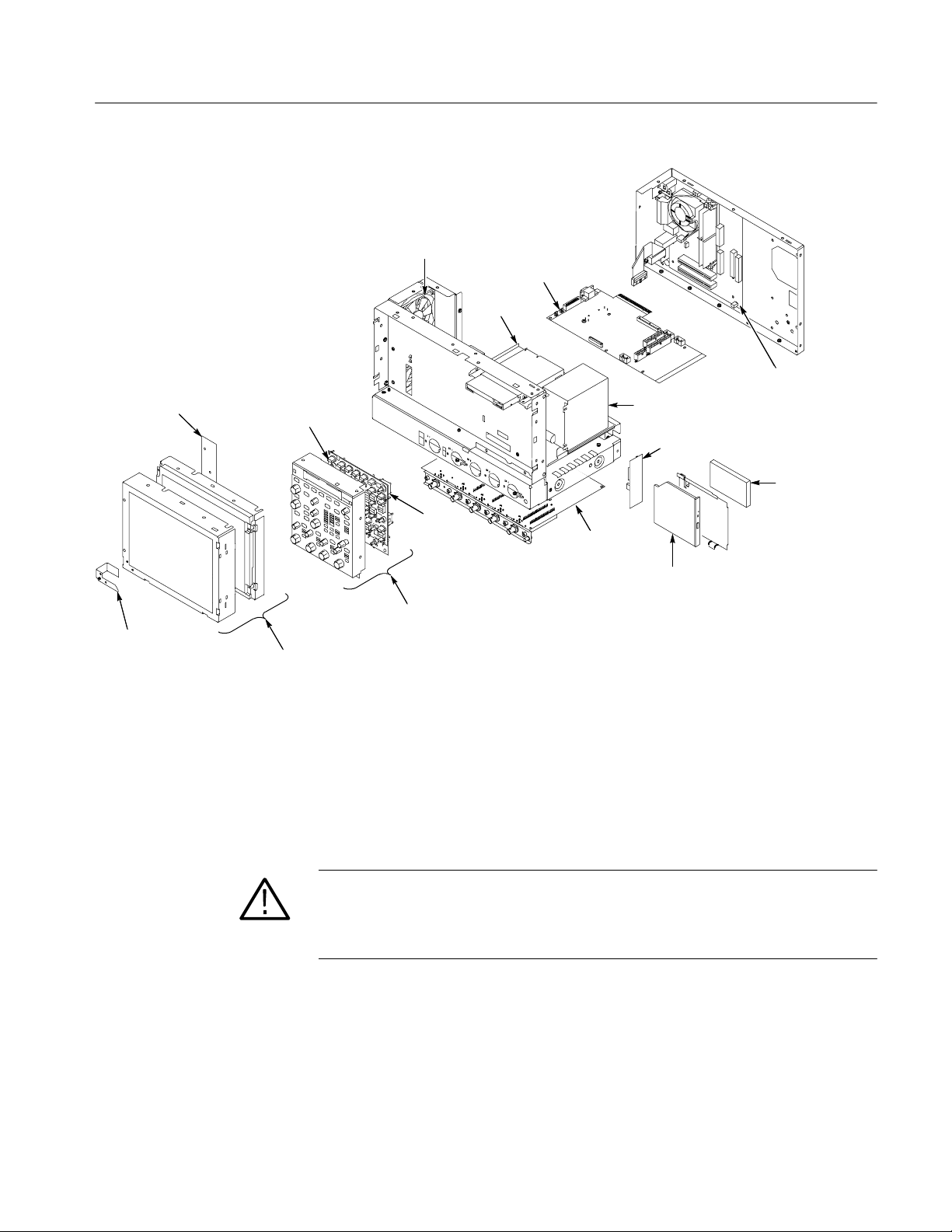
Installation Instructions
Display adapter board
Power flex
circuit
Front panel
keypad
Display assembly
Fans
Front panel
assembly
Front
panel
board
PC interface
board
Floppy disk
drive
Motherboard
Power supply assembly
HD/CD-drive Interconnect board
Hard drive
Acquisition
board
CD-drive
Figure 2: Internal modules
Display Assembly
Removal
1. Locate module to be removed: Locate the Display assembly; see Figure 2.
2. Orient the oscilloscope: Set the oscilloscope on the work surface with its
front panel facing you.
CAUTION. To avoid damage to the front panel Standby/On switch assembly, do
not set the Display module assembly on a work surface. Sliding the oscilloscope
over the edge of the work surface could break off the On/Standby switch
assembly.
LCD\Touch Screen Replacement Kit
9
Page 12

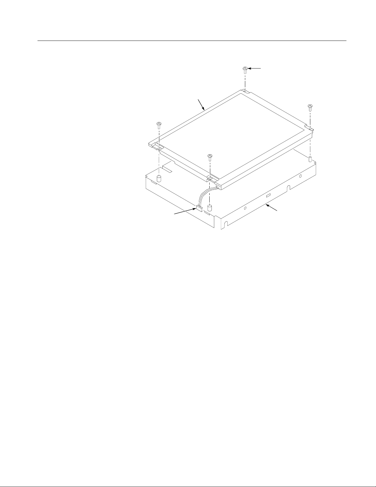
Installation Instructions
3. Remove the Display assembly: See Figure 3.
a. Remove the four T-15 Torx screws that secure the display assembly to
the chassis.
b. Grasp the display assembly at the finger reliefs located at the top-right
and bottom-left corners of the display assembly and pull forward far
enough to allow access to the flex cable connector.
c. Disconnect J5 flex cable from the display assembly. Remove the display
module assembly from the oscilloscope.
d. Set the display assembly aside for later reassembly of the Inverter and
Display circuit boards to the new display assembly with touch screen.
T-15 Torx
screw (4)
J5 Flex cable
Finger relief
Display
assembly
Finger relief
Finger relief
Figure 3: Display removal
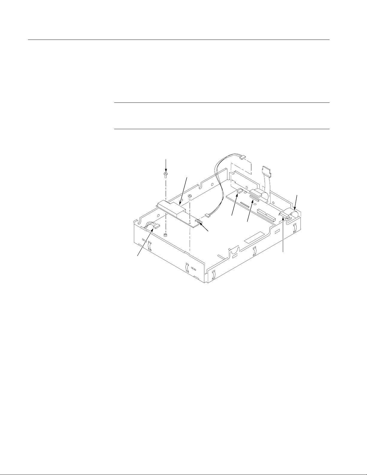
4. Remove and disconnect the following from the old display assembly:
a. Disconnect cables J1, J4 and J7 from the Display Adapter circuit board.
SeeFigure4,onpage11.
10
b. Disconnect LCD light connector (S) from the Inverter circuit board.
LCD\Touch Screen Replacement Kit
Page 13

Installation Instructions
c. Disconnect the cable that connects between the Display Adapter (J6) and
Inverter (CN1) circuit boards. Save the cable for later reassembly of the
new display assembly.
d. Remove the two number 0 Phillips screws that secure the Inverter circuit
board to the display assembly. Save the Inverter board and Phillips
screws for later reassembly onto the new display assembly.
5. Install the old LCD assembly to the new display assembly, using the four
T-15 Torxdrive screws from the old display assembly.
J1
J6
J4
Figure 4: Remove inverter circuit board
Cable
CN1
J7
S
LCD Light connector
Remove
screws (2)
Inverter board
LCD\Touch Screen Replacement Kit
11
Page 14

Installation Instructions
CAUTION. To prevent damage to the touch screen from scratches or cuts, make
sure you take care not to contact the screen surface with any sharp tools.
a. Separate the display assembly by carefully prying the (outer) touch
screen panel assembly from the (inner) LCD assembly. Insert a
flat-bladed screwdriver in the access notches to push out on the Touch
panel assembly. See Figure 5.
b. Remove the four T-15 Torxdrive screws that secure the old LCD to the
old LCD assembly. See Figure 6 for T-15 screw locations.
c. Install the old LCD into the new LCD assembly using the T-15 screws
removed from the old LCD assembly.
LCD assembly
LCD module
Figure 5: Remove/install the LCD assembly and touch screen panel
Touch screen
panel
Access taps
Access notches
12
LCD\Touch Screen Replacement Kit
Page 15
LCD
Installation Instructions
T-15 Torxdrive screws (4)
Display light connector
LCD assembly
Figure 6: Install the old display to the new rear bracket assembly
6. Install the new LCD assembly and touch screen panel by sliding them
together until tabs snap into the notches. See Figure 6.
7. Install the old Inverter circuit board into the new LCD assembly using the
two number 0 Phillips screws removed from the old display assembly.
LCD\Touch Screen Replacement Kit
13
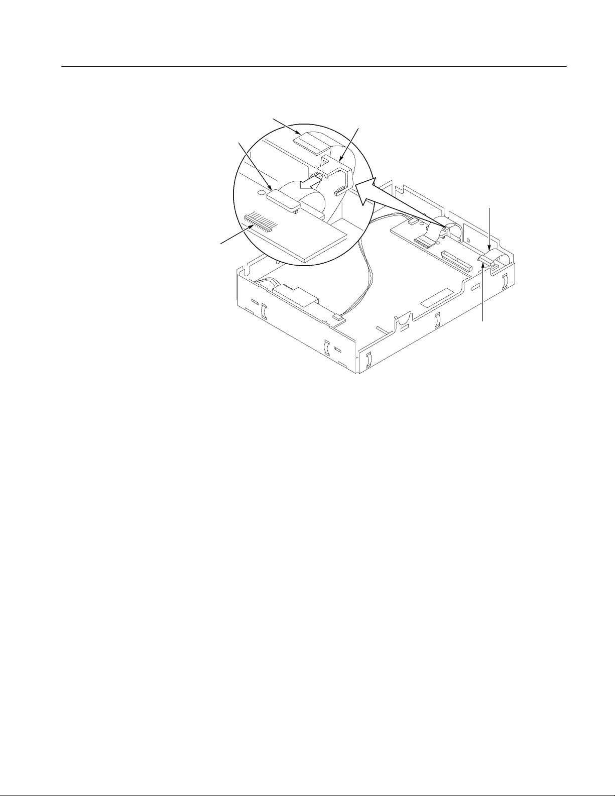
Page 16
Installation Instructions
8. Connect (CN1) to (J6) connectors to the Inverter/Display Adapter circuit
boards. See Figure 7.
9. Connect LCD light connector (S) to the Inverter circuit board.
NOTE. The LCD and Inverter/Display connector housings have contacts visible
on one side; make sure this side is facing up toward the installer when connecting the cable to both circuit boards.
Screws (2)
Inverter board
Power flex circuit
CN1
Display light cable
connector
Figure 7: Install the inverter circuit board
J6
J4
J7
14
LCD\Touch Screen Replacement Kit
Page 17
Installation Instructions
Touch screen
cable
J4
J1
Slide the clip
over connector
Figure 8: Cable clamp installation detail
Power flex circuit
J7
Gamma Settings
10. Connect the display cable to J4 on the Display Adapter circuit board. Slide
the cable clamp (provided in this kit) over the cable and under the Display
Adapter circuit board to secure the cable to the connector.
See Figure 8.
11. Connect the touch screen cable to the J1 connector on the Display Adapter
circuit board.
12. Do in reverse steps 1 through 3, on page 10, to reinstall the Display
assembly into the instrument.
13. Reinstall the front panel trim, line fuse, and line cord. Do in reverse steps 1
through 3, page 7.
Use the following gamma setting procedure to get the optimum display. Try both
settings, Steps 8 and 12 on page 18, to determine what display looks best to you.
1. Right click on the desktop.
2. Click the Properties menu.
LCD\Touch Screen Replacement Kit
15
Page 18
Installation Instructions
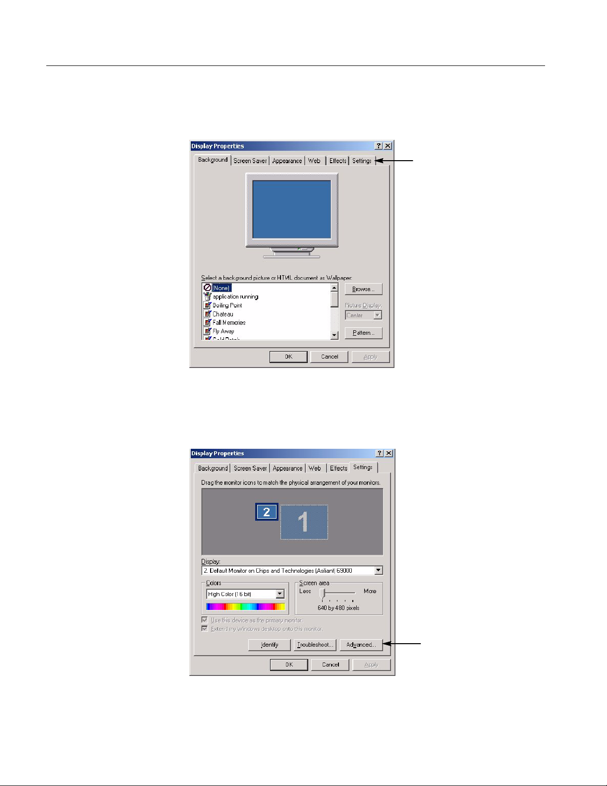
3. Click the Settings tab. See Figure 9.
Figure 9: Settings tab
4. Click the Advance button. See Figure 10.
16
Figure 10: Advance button
LCD\Touch Screen Replacement Kit
Page 19
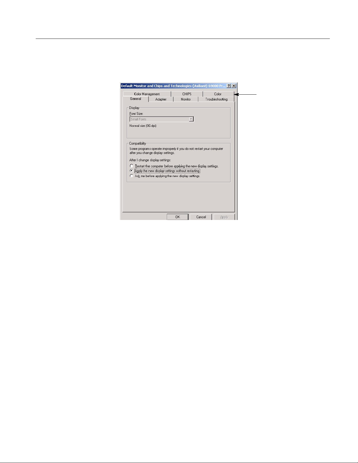
5. Click the Color tab. See Figure 11.
Installation Instructions
Figure 11: Color tab
LCD\Touch Screen Replacement Kit
17
Page 20
Installation Instructions
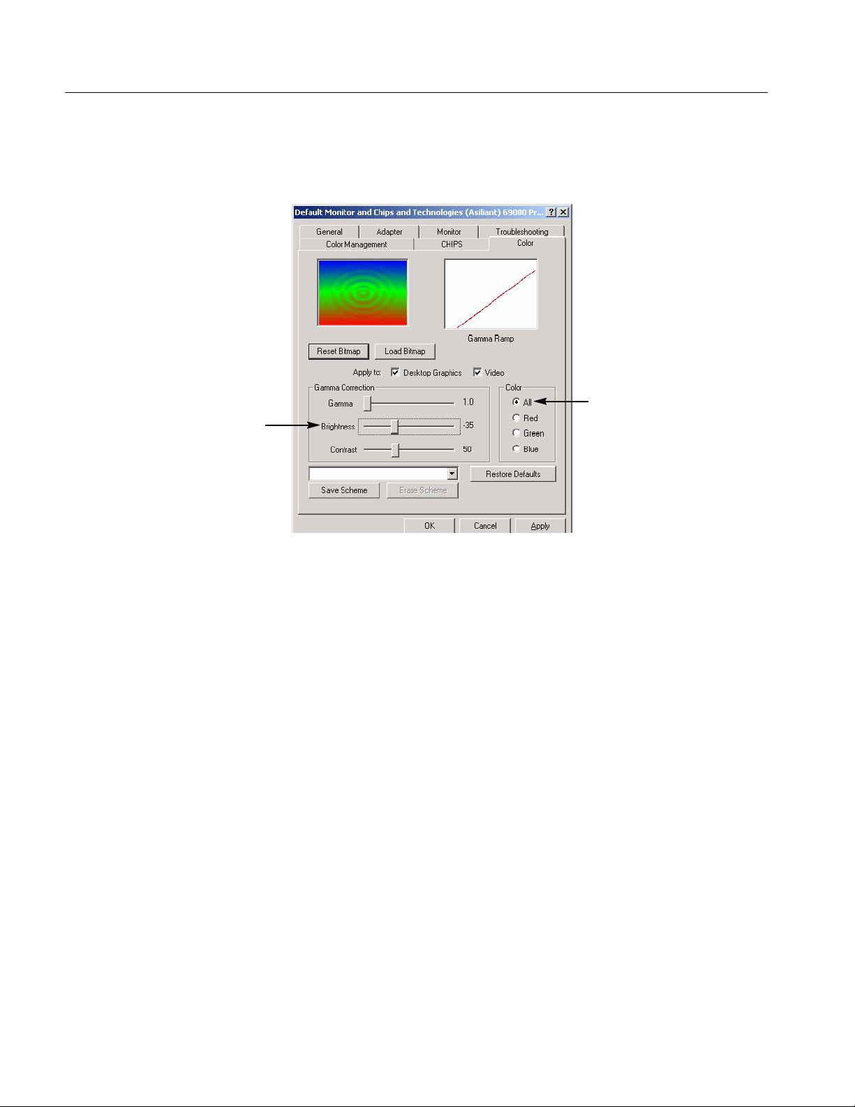
6. Select the Desktop graphics and Video buttons. See Figure 12.
7. In the Color menu select All. See Figure 12.
Touch Screen Set Up
Figure 12: Brightness and button settings
8. Slide the brightness bar to --35. All. See Figure 12.
9. Click OK.
10. ClickOKontheDisplaymenu.
11. Go to the Scope display to see how the display looks.
12. Repeat Steps 1 through 11, except set the slide the brightness bar to --40 in
step 8.
13. Set the gamma setting that looks best to you, --35 or --40.
For the touch screen set-up instructions, refer to the CD booklet that came with
your Touch Screen Switcher Tool CD.
g End of document g
18
LCD\Touch Screen Replacement Kit
 Loading...