

Page 1

Instructions
050-3695-00
F-Connector Replacement for 8VSB Interface
MTM400 MPEG Transport Stream Monitor &
MTS400 Series MPEG Test Systems
075-0975-00
Warning
The servicing instructions are for use by qualified
personnel only. To avoid personal injury, do not
perform any servicing unless you are qualified to
do so. Refer to all safety summaries prior to
performing service.
www.tektronix.com
*P075097500*
075097500
Page 2

Copyright © Tektronix. All rights reserved. Licensed software products are owned by Tektronix or its subsidiaries or
suppliers, and are protected by national copyright laws and international treaty provisions.
Tektronix products are covered by U.S. and foreign patents, issued and pending. Information in this publication supercedes
that in all previously published material. Specifications and pri ce change privileges reserved.
TEKTRONIX and TEK are registered trademarks of Tektronix, Inc.
Contacting Tektronix
Tektronix, Inc.
14200 SW Karl Braun Drive
P.O. Box 500
Beaverton, OR 97077
USA
For product information, sales, service, and technical support:
H In North America, call 1-800-833-9200.
H Worldwide, visit www.tektronix.com to find contacts in your area.
Page 3

General Safety Summary
Review the following safety precautions to avoid injury and prevent damage to
this product or any products connected to it.
To avoid potential hazards, use this product only as specified.
Only qualified personnel should perform service procedures.
While using this product, you may need to access other parts of a larger system.
Read the safety sections of the other component manuals for warnings and
cautions related to operating the system.
ToAvoidFireor
Personal Injury
Use Proper Power Cord. Use only the power cord specified for this product and
certified for the country of use.
Connect and Disconnect Properly. Do not connect or disconnect probes or test
leads while they are connected to a voltage source.
Ground the Product. This product is grounded through the grounding conductor
of the power cord. To avoid electric shock, the grounding conductor must be
connected to earth ground. Before making connections to the input or output
terminals of the product, ensure that the product is properly grounded.
Observe All Terminal Ratings. To avoid fire or shock hazard, observe all ratings
and markings on the product. Consult the product manual for further ratings
information before making connections to the product.
Do not apply a potential to any terminal, including the common terminal, that
exceeds the maximum rating of that terminal.
Power Disconnect. The power cord disconnects the product from the power
source. Do not block the power cord; it must remain accessible to the user at all
times.
Replace Batteries Properly. Replace batteries only with the specified type and
rating.
Do Not Operate Without Covers. Do not operate this product with covers or panels
removed.
Do Not Operate With Suspected Failures. If you suspect there is damage to this
product, have it inspected by qualified service personnel.
Avoid Exposed Circuitry. Do not touch exposed connections and components
when power is present.
Use Proper Fuse. Use only the fuse type and rating specified for this product.
Do Not Operate in Wet/Damp Conditions.
F-Connector Replacement for 8VSB Interface
i
Page 4

General Safety Summary
Do Not Operate in an Explosive Atmosphere.
Keep Product Surfaces Clean and Dry.
Provide Proper Ventilation. Refer to the manual’s installation instructions for
details on installing the product so it has proper ventilation.
Terms in this Manual
Symbols and Terms
on the Product
These terms may appear in this manual:
WARNING. Warning statements identify conditions or practices that could result
in injury or loss of life.
CAUTION. Caution statements identify conditions or practices that could result in
damage to this product or other property.
These terms may appear on the product:
H DANGER indicates an injury hazard immediately accessible as you read the
marking.
H WARNING indicates an injury hazard not immediately accessible as you
read the marking.
H CAUTION indicates a hazard to property including the product.
The following symbol(s) may appear on the product:
CAUTION
Refer to Manual
WARNING
High Voltage
ii
Protective Ground
(Earth) Terminal
Standby
F-Connector Replacement for 8VSB Interface
Page 5

Service Safety Summary
Only qualified personnel should perform service procedures. Read this Service
Safety Summary and the General Safety Summary before performing any service
procedures.
Do Not Service Alone. Do not perform internal service or adjustments of this
product unless another person capable of rendering first aid and resuscitation is
present.
Disconnect Power. To avoid electric shock, switch off the instrument power, then
disconnect the power cord from the mains power.
Use Care When Servicing With Power On. Dangerous voltages or currents may
exist in this product. Disconnect power, remove battery (if applicable), and
disconnect test leads before removing protective panels, soldering, or replacing
components.
To avoid electric shock, do not touch exposed connections.
F-Connector Replacement for 8VSB Interface
iii
Page 6

Service Safety Summary
iv
F-Connector Replacement for 8VSB Interface
Page 7

Kit Description
Products
Kit Parts List
This kit provides parts and instructions for replacing the F-connector on an
8VSB interface card for a MTM400 MPEG Transport Stream Monitor or a
MTS400 Series MPEG Test system. The replacement F-connector has a longer
threaded section to ensure a more secure cable connection.
There are separate replacement instructions for the MTM400 monitor and the
MTS400 Series test system. Use the appropriate instructions for the type of
instrument your are servicing.
This document supports Tektronix modification: ECR31519.
MTM400 VS All instruments
MTS400 VS All instruments
MTS430 VS All instruments
Quantity Part number Description
1EA 103-0458-00 ADAPTER, CONN; F FEMALE TO QUICK DISCONNECT MALE
ADAPTER
1EA 075-0975-00 KIT INSTRUCTION; F-CONNECTOR REPLACEMENT, 8VSB
INTERFACE; 050-3695-00
F-Connector Replacement for 8VSB Interface
1
Page 8

Kit Description
2
F-Connector Replacement for 8VSB Interface
Page 9

Replacement Instructions -- MTM400 Monitor
These instructions are for personnel who are familiar with servicing the
MTM400 monitor. If you need further details for disassembling or reassembling
the instrument, contact your nearest Tektronix Service Center or Tektronix
Factory Service for assistance.
CAUTION. To prevent static discharge damage, service the product only in a
static-free environment. Observe standard handling precautions for static-sensitive devices while installing this kit. Always wear a grounded wrist strap,
grounded foot strap, and static resistant apparel while installing this kit.
Only qualified personnel should perform this procedure. Read the General Safety
Summary and the Service Safety Summary located at the beginning of these
instructions before performing the following procedure.
Minimum Tool and Equipment List
Replacement Procedure
Perform the following steps to replace the F-connector on the 8VSB interface
card in your MTM400 monitor.
Preparation
If necessary, disconnect any signal and power cables from the instrument,
remove the instrument from the instrument rack, and then place the instrument
on a static-free workbench.
WARNING. To prevent serious injury or death from electrical shock, do not
operate the instrument with the cover or panels removed. Disconnect power from
the instrument before removing the covers or panels.
Required tools and equipment Part number
Anti-static wrist strap NA
Screwdriver with T-10, T-15, and T-20 TORX tips NA
Wrench, 7/16 inch NA
F-Connector Replacement for 8VSB Interface
3
Page 10

Replacement Instructions -- MTM400 Monitor
Remove the Instrument
Cover
Remove the 8VSB
Interface Card
1. Remove the 21 retaining screws (see Figure 1) and lift the cover clear of the
instrument.
21 T10
TORX screws
Figure 1: Removing the instrument cover
2. Locate the 8VSB interface card in your instrument (see Figure 2). The
interface card is mounted on the right side of the instrument as viewed from
the rear.
3. Remove the cables connected to the interface card (see Figure 2 and
Tab le 1):
a. Disconnect the ribbon cable from the connector labeled J14 on the
interface card.
b. Disconnect the eight-wire power cable from the connector labeled JR1
on the interface card.
4. Remove the six retaining screws from the interface card and remove the
three retaining screws from the rear panel (see Figure 3).
Table 1: Interface card connectors
Interface card connection Cable type Connects to location Function
JR1 Eight wires J7 on the Power Distribution card Power
J14 Ribbon J750 on the TS Processor card Data (serializer)
4
F-Connector Replacement for 8VSB Interface
Page 11

Replacement Instructions -- MTM400 Monitor
Figure 2: 8VSB interface card location
Ribbon
cable
Eight-wire
power cable
Interface
card
Retaining screws (6)
Retaining screws (3)
Figure 3: Interface card retaining screw locations
F-Connector Replacement for 8VSB Interface
5
Page 12

Replacement Instructions -- MTM400 Monitor
5. Lift the interface card clear of the instrument and place the card on a
static-free work surface.
CAUTION. To prevent static damage to the removed interface card, be sure to
work on it only in a static-free environment. Failure to properly protect the
interface card might result in the card needing repair before it will operate
properly when reinstalled.
Replace the F-Connector
6. Remove the three retaining screws from the top circuit board of the interface
card (see Figure 4).
Remove 3 screws
Figure 4: Top circuit board retaining screw locations
7. Grasp the rear panel on the interface card, and then slide the top circuit board
away from the rear panel until the F-connector is disengaged from the circuit
board (see Figure 5).
8. Use a 7/16 inch wrench to remove the retaining nut from the F-connector
(see Figure 6), and then remove the F-connector from the rear panel.
9. Install the replacement F-connector supplied with this kit in the same
rear-panel location, and then use the wrench to tighten the retaining nut.
6
F-Connector Replacement for 8VSB Interface
Page 13

Replacement Instructions -- MTM400 Monitor
F-connector
Figure 5: Disengaging the F-connector from the top circuit board
Replace the
F-connector
Figure 6: Replacing the F-connector
F-Connector Replacement for 8VSB Interface
7
Page 14

Replacement Instructions -- MTM400 Monitor
10. Grasp the rear panel on the interface card, and then slide the top circuit board
towards the rear panel until the F-connector is engaged with the circuit board
(see Figure 7).
Reinstall the 8VSB
Interface Card
F-connector
Figure 7: Engaging the F-connector with the top circuit board
11. Install the three retaining screws in the top circuit board of the interface card
(see Figure 4 on page 6).
12. Position the interface card in the instrument chassis, and then install the six
retaining screws in the interface card and install the three retaining screws in
the rear panel (see Figure 3 on page 5).
13. Connect the cables to the interface card (see Figure 2 on page 5 and Table 1
on page 4):
a. Connect the ribbon cable to the connector labeled J14 on the interface
card.
b. Connect the eight-wire power cable to the connector labeled JR1 on the
interface card.
Reinstall the Instrument
8
Cover
14. Position the cover on the instrument chassis and install the 21 retaining
screws (see Figure 1 on page 4).
F-Connector Replacement for 8VSB Interface
Page 15

Replacement Instructions -- MTM400 Monitor
Verify Operation
To verify the operation of the MTM400 monitor, you will need to access the
instrument RUI using a PC meeting the system requirements listed in Table 2.
The MTM400 monitor and the PC need to be connected to the same Ethernet
network.
Table 2: MTM400 monitor RUI platform requirements
Characteristic Description
Minimum Specification 1 GHz Intel Pentium Processor (Preferred: 2 GHz)
Operating System Microsoft Windows operating systems Windows 2000 or Windows XP
(Recommended: Windows XP Pro)
Disk space 2GBfreediskspace
Ethernet 10/100-base T
Installed software Microsoft Internet Explorer, Version 6.0 minimum;
Microsoft Java Virtual Machine installed, Version 5.0 minimum
RAM 1GB
CD-ROM Drive 8x
Display 1024 x 768 pixel video monitor with 16 available colors
Perform the following steps to verify that the MTM400 monitor and the 8VSB
interface card you reinstalled are operating properly:
NOTE. This procedure assumes that the MTM400 monitor is operating with
firmware version 2.6.1.
1. Connect the MTM400 monitor to an Ethernet network, power up the
instrument, and then wait for the instrument to initialize. When the
initialization process is complete, the instrument beeps and the front-panel
LEDs illuminate.
F-Connector Replacement for 8VSB Interface
9
Page 16

Replacement Instructions -- MTM400 Monitor
2. Using a PC connected to the same Ethernet network as the MTM400
monitor, perform the following steps to open the MTM400 monitor RUI:
NOTE. The following procedure uses Microsoft Internet Explorer to open the
MTM400 monitor RUI. You can also access the RUI using the Tektronix Web
Monitoring Systems Manager (WebMSM). The instructions for using WebMSM
are located in the WebMSM User Manual (Tektronix part number 071-1239-xx).
a. Launch Microsoft Internet Explorer.
b. In the address bar of the Web browser, enter the network identity or
IP address of the MTM400 monitor, for example: http://TSMonitor01 or
http://111.222.333.444.
When you press the Enter key, a Java applet is downloaded from the
MTM400 monitor and launched. The file size is approximately 1.5 MB;
the download time will depend on the network speed and traffic.
CAUTION. The Java applet will not run unless a temp directory is properly
configured on the PC. A temp directory is set up by default in the Windows XP
operating system; previous operating systems may require operator action.
The Java applet will not run unless the Microsoft Java Virtual Machine is
installed. Type jview at the command prompt to verify that it is installed and that
the version is 5.00.3809 or greater. If it is not installed, obtain the installation
file from the Tektronix Web site.
If the Sun Virtual Machine has also been installed, the Sun Virtual Machine must
not be set as the default in the Java control panel or Internet Explorer options,
advanced tab.
3. After the Java applet is downloaded, the MTM400 monitor splash screen
will appear, and then be quickly overlaid by the Login Details dialog box
(see Figure 8).
4. In the Login Details dialog box, select Administrator from the User
drop-down list.
NOTE. Do not select User from the drop-down list. The User login type does not
have sufficient permissions to perform software option upgrades.
10
5. Enter the appropriate password, and then click OK to accept the login
details. The default password for the Administrator login type is tek.
F-Connector Replacement for 8VSB Interface
Page 17

Replacement Instructions -- MTM400 Monitor
Figure 8: Logging on to MTM400 monitor
6. After you log on to the MTM400 monitor, the Hotspot view is displayed
(see Figure 9). Click the Stream button to open the Stream view. Figure 10
shows an example Stream view.
Figure 9: Hotspot view
7. In the Stream view, click the Config button to open the Configuration screen
(see Figure 11).
8. In the Configuration screen, use the Interface drop-down list to select the
8VSB interface.
9. If you are able to connect to the MTM400 monitor, display the RUI, and
select the 8VSB interface in the Configuration screen, then the instrument is
operating normally.
F-Connector Replacement for 8VSB Interface
11
Page 18

Replacement Instructions -- MTM400 Monitor
Figure 10: Stream view example
ATSC
8VSBInterface
Figure 11: Configuration screen
No Extensions
12
F-Connector Replacement for 8VSB Interface
Page 19

Replacement Instructions -- MTS400 Series Systems
These instructions are for personnel who are familiar with servicing the MTS400
Series systems. If you need further details for disassembling or reassembling the
instrument, contact your nearest Tektronix Service Center or Tektronix Factory
Service for assistance.
CAUTION. To prevent static discharge damage, service the product only in a
static-free environment. Observe standard handling precautions for static-sensitive devices while installing this kit. Always wear a grounded wrist strap,
grounded foot strap, and static resistant apparel while installing this kit.
Only qualified personnel should perform this procedure. Read the General Safety
Summary and the Service Safety Summary located at the beginning of these
instructions before performing the following procedure.
Minimum Tool and Equipment List
Required tools and equipment Part number
Anti-static wrist strap NA
Screwdriver with T-10, T-15, and T-20 TORX tips NA
Flat blade screwdriver NA
Wrench, 7/16 inch NA
F-Connector Replacement for 8VSB Interface
13
Page 20
Replacement Instructions -- MTS400 Series Systems
Replacement Procedure
Perform the following steps to replace the F-connector on the 8VSB interface
module in your MTS400 Series system.
Preparation
Remove the Cabinet
If necessary, disconnect any signal and power cables from the instrument, and
then place the instrument on a static-free workbench.
WARNING. To prevent serious injury or death from electrical shock, do not
operate the instrument with the cover or panels removed. Disconnect power from
the instrument before removing the covers or panels.
1. Install the protective cover on the front of the instrument and place the
instrument on the working surface with the rear panel facing up.
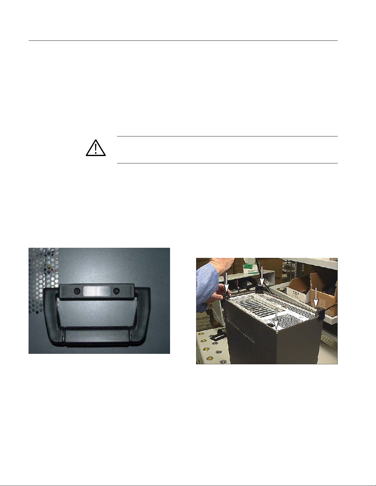
2. Remove the handle from the side of the instrument and remove the four feet
from the rear of the instrument (see Figure 12). Retain the screws for
reinstallation.
Figure 12: Removing the handle and feet from the cabinet
14
F-Connector Replacement for 8VSB Interface
Page 21

Replacement Instructions -- MTS400 Series Systems
WARNING. To prevent damage to the EMI shielding and injury to yourself,
use care when touching the EMI shielding strips around the front of the chassis.
If you accidentally bend the “fingers” of the strip, it could create sharp
protruding edges, which may cut you as you handle the chassis.
3. Position a flat blade screwdriver below the PEM nut on the rear panel as
shown in Figure 13. Use the screwdriver as a lever to pry the cabinet loose
from the chassis. Loosen each side alternately until the cabinet is released
from the EMI gasket.
4. Slide the cabinet up and off the chassis.
Figure 13: Prying the cabinet loose from the chassis
F-Connector Replacement for 8VSB Interface
15
Page 22

Replacement Instructions -- MTS400 Series Systems
Remove the 8VSB
Interface Module
5. Remove the circuit board retaining plate (see Figure 14).
6. The 8VSB interface module is installed in slots 4 and 5 (see Figure 15).
Disconnect the interface cable from the 8VSB module.
Remove
screws (5)
Remove top retaining screw
Circuit board
retaining plate
Carefully pull up on the
Module
Slide module into
slot when replacing
module to loosen it from
the backplane and lift it
out of the bay.
Remove rear
retaining screw
16
Figure 14: Removing a module
7. Remove the two retaining screws from the top of the 8VSB module and also
the retaining screw from the top of the bracket in slot 6 (see Figure 15).
8. Remove the two rear retaining screws from the bottom of the 8VSB module.
F-Connector Replacement for 8VSB Interface
Page 23

8VSB interface brackets
Replacement Instructions -- MTS400 Series Systems
Slot numbers
123456789101112
Figure 15: MTS400 Series system rear panel
9. As you hold back any overlapping cables, carefully pull up on the 8VSB
module to loosen it from the connectors on the Backplane board. You may
have to alternate lifting on the front and rear of the module to work it loose
from the connectors and the chassis.
10. Lift the interface module clear of the instrument and place the board on a
static-free work surface.
CAUTION. To prevent static damage to the removed board, be sure to only work
on it in a static free work environment. Failure to properly protect the board may
result in the board needing repair before it will operate properly when reinstalled.
F-Connector Replacement for 8VSB Interface
17
Page 24

Replacement Instructions -- MTS400 Series Systems
Replace the F-connector
11. Remove the three retaining screws from the top circuit board of the interface
module (see Figure 16).
Remove 3 screws
Figure 16: Top circuit board retaining screw locations
12. Grasp the rear panel on the interface module, and then slide the top circuit
board away from the rear panel until the F-connector is disengaged from the
circuit board (see Figure 17).
13. Use a 7/16 inch wrench to remove the retaining nut from the F-connector
(see Figure 18), and then remove the F-connector from the rear panel.
14. Install the replacement F-connector supplied with this kit in the same
rear-panel location, and then use the wrench to tighten the retaining nut.
18
F-Connector Replacement for 8VSB Interface
Page 25

Replacement Instructions -- MTS400 Series Systems
F-connector
Figure 17: Disengaging the F-connector from the top circuit board
Replace the
F-connector
Figure 18: Replacing the F-connector
F-Connector Replacement for 8VSB Interface
19
Page 26

Replacement Instructions -- MTS400 Series Systems
15. Grasp the rear panel on the interface module, and then slide the top circuit
board towards the rear panel until the F-connector is engaged with the circuit
board (see Figure 19).
Reinstall the 8VSB
Interface Module
Figure 19: Engaging the F-connector with the top circuit board
16. Install the three retaining screws in the top circuit board of the interface
module (see Figure 16 on page 18).
17. Position the interface module in slots 4 and 5 of the instrument chassis
(see Figure 15 on page 17). As you hold back any overlapping cables,
carefully align the connector on the bottom edge of the module with the
connector on the Backplane board, and then apply firm pressure to
completely seat the module in the Backplane board connector.
18. Install the two retaining screws in the top of the 8VSB interface module and
also the retaining screw in the top of the bracket in slot 6.
19. Install the two rear retaining screws in the bottom of the 8VSB interface
module.
20. Reconnect the interface cable to the 8VSB interface module (see Figure 20).
20
F-Connector Replacement for 8VSB Interface
Page 27

Replacement Instructions -- MTS400 Series Systems
Connected to Controller board
Figure 20: Reconnecting the 8VSB interface cable
Reinstall the Cabinet
21. Position the instrument on the working surface with the rear panel facing up.
22. Slide the cabinet down and onto the chassis.
CAUTION. To prevent damage to the instrument, make sure that the internal
cables do not catch when you slide the cabinet back onto the chassis. Make sure
that the edges of the cabinet go under the retaining tabs around the front of the
chassis. You may have to push on the side of the cabinet to get all of the edges
under the tabs and over the EMI gasket.
Connected to 8VSB interface module
At the rear of the chassis, you may have to push on the sides of the cabinet to get
the rear of the cabinet to fit over the edges of the chassis and EMI gasket.
23. Install the handle on the side of the instrument and install the four feet on to
the rear of the instrument (see Figure 12 on page 14).
Verify Operation
To verify the operation of the MTS400 Series system, perform the performance
verification procedure in the MTS400 Series MPEG Test Systems Specifications
and Performance Verification Technical Reference (Tektronix part number
071-1724-05). You need to use version --05 or greater of this document in order
to verify the 8VSB interface module.
g End of document g
F-Connector Replacement for 8VSB Interface
21
Page 28

 Loading...