

Page 1

Instructions
050-3625-00 and Above
TMS817 and TMS818 PCI Express
Slot Adapter Board Modification
075-0892-00
Warning
The servicing instructions are for use by qualified
personnel only. To avoid personal injury, do not
perform any servicing unless you are qualified to
do so. Refer to all safety summaries prior to
performing service.
www.tektronix.com
*P075089200*
075089200
Page 2

Copyright © Tektronix, Inc. All rights reserved. Licensed software products are owned by Tektronix or its subsidiaries or
suppliers, and are protected by national copyright laws and international treaty provisions.
Tektronix products are covered by U.S. and foreign patents, issued and pending. Information in this publication supercedes
that in all previously published material. Specifications and price change privileges reserved.
TEKTRONIX and TEK are registered tradem arks of Tektronix, Inc.
Contacting Tektronix
Tektronix, Inc.
14200 SW Karl Braun Drive
P.O. Box 500
Beaverton, OR 97077
USA
For product information, sales, service, and technical support:
H In North America, call 1-800-833-9200.
H Worldwide, visit www.tektronix.com to find contacts in your area.
Page 3

Service Safety Summary
Only qualified personnel should perform service procedures. Read this Service
Safety Summary and the General Safety Summary in the product service manual
or the instruction manual.
Do Not Service Alone. Do not perform internal service or adjustments of this
product unless another person capable of rendering first aid and resuscitation is
present.
Disconnect Power. To avoid electric shock, switch off the instrument power, then
disconnect the power cord from the mains power.
Use Care When Servicing With Power On. Dangerous voltages or currents may
exist in this product. Disconnect power, remove battery (if applicable), and
disconnect test leads before removing protective panels, soldering, or replacing
components.
To avoid electric shock, do not touch exposed connections.
PCI Express Slot Adapter Board Modification
1
Page 4

Service Safety Summary
2
PCI Express Slot Adapter Board Modification
Page 5

Kit Description
This kit provides parts and instructions for modifying the PCI Express Slot
Adapter board. When you install the PCI Express Interposer Fix circuit board,
you must also cut two traces on the original Slot Adapter board and solder six
connections between the Slot Adapter board and the new PCI Express Slot
Adapter board.
This document supports Tektronix modification: ECR30395
Products
TMS817 and TMS818 All PCI Express Slot Adapter boards
PCI Express Bus Supports
Minimum Tool and Equipment List
Required tools and equipment Part number
Exacto knife
Kit Parts List
Soldering iron and solder
Needle-nose pliers
Circuit/figure
number
-- 1EA 389-3846-XX Ckt BD Subassy; PCI Express Interposer Fix
-- 1EA 075-0892-00 Kit instructions, 050-3625-XX
-- 1EA 175-0729-XX Wire,Electrical; STRD,22 AWG,150V RMS,Red,
-- 1EA 175-0523-XX Wire,Electrical; STRD,22 AWG,300V
-- 1EA 174-5282-XX Cable Assy; 30 AWG,120 Ω,Unsheilded,Twisted
Quantity Part number Description
TMS817,TMS818:
PVC, 5 inches
RMS,black,PVC,UL style 1430, 5 inches
Pair,Black and Brown,12 inches
1EA 253-0176-XX Tape,Press Sens; Vinyl Foam,0.5 X
0.062,double sided adhesive
PCI Express Slot Adapter Board Modification
3
Page 6

Kit Description
4
PCI Express Slot Adapter Board Modification
Page 7

Installation Instructions
These instructions are for personnel who are familiar with servicing the product.
If you need further details for disassembling or reassembling the product, refer to
the appropriate product manual. Contact your nearest Tektronix, Inc., Service
Center or Tektronix Factory Service for installation assistance.
CAUTION. To prevent static discharge damage, service the product only in a
static-free environment. Observe standard handling precautions for static-sensitive devices while installing this kit. Always wear a grounded wrist strap,
grounded foot strap, and static-resistant apparel while installing this kit.
Remove
Perform the following steps to modify the Slot Adapter board:
1. Place the Slot Adapter board with the black slot connector visible. See
Figure 1.
Figure 1: Cut the board traces
Slot Adapter board
(slot connector visible)
PCI Express Slot Adapter Board Modification
5
Page 8

Installation Instructions
CAUTION. To prevent damage to other traces on the Slot Adapter board , use care
when removing the following two traces.
2. Using an Exacto knife, cut the two traces as close as possible to the J7
connector (between J7 and J2).
3. Using an Exacto knife, separate the traces from pin 3 of the J7 connector on
the Slot Adapter board by lifting the traces and peeling them towards the J2
slot connector. See Figure 2.
NOTE. The traces on the Slot Adapter boards are removed easily with the help of
needle-nose pliers. If the traces do not completely separate from the board, use
an Exacto knife to cut the traces as close to the J2 slot connector (black) as
possible.
J2 (two traces)
Slot Adapter board
Figure 2: Removing the two traces (side B)
J7
6
PCI Express Slot Adapter Board Modification
Page 9

Installation Instructions
4. Turn the Slot Adapter board over to the solder side of the slot connector.
5. Remove the center pin (pin 2) from the J7 square pin connector. See
Figure 3.
Slot Adapter board
(slot connector not
visible)
Center pin J7
Figure 3: Removing the center pin from J7
PCI Express Slot Adapter Board Modification
7
Page 10

Installation Instructions
Install
Perform the following steps to install the Interposer Fix board:
1. Place the Interposer Fix board as shown in Figure 4.
2. Attach double-sided adhesive vinyl-foam tape to the Interposer Fix board.
SeeFigure4.
Figure 4: Tape attached to Interposer Fix board
3. Attach the Interposer Fix board to the Slot Adapter board. See Figure 5.
NOTE. Do not cover the mounting holes on the Slot Adapter board. See Figure 5.
Interposer Fix board
Mounting
holes
Figure 5: Correctly attached Interposer Fix board
8
PCI Express Slot Adapter Board Modification
Page 11
Installation Instructions
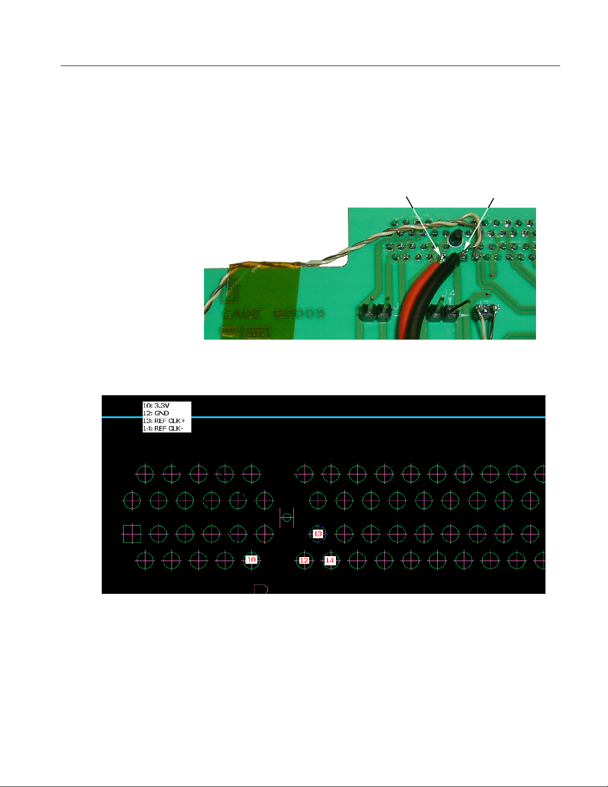
4. Solder the red power wire to pin 10 of the J2 connector on the back of the
slot connector. See Figures 6 and 7.
5. Solder the black ground wire to pin 12 of the J2 connector on the back of the
Slot connector.
Pin 10 of J2 Pin 12 of J2
Figure 7: J2 pin locations
Figure 6: Solder power and ground wires
PCI Express Slot Adapter Board Modification
9
Page 12

Installation Instructions
6. Solder the other end of the red power wire to pin 1 of J1 on the Interposer
Fix board (labeled 3.3 V).
7. Solder the other end of the black ground wire to pin 2 of J1 on the Interposer
Fix board (labeled GND).
Pin1ofJ1Pin2ofJ1
Figure 8: Attach red and black wires to Interposer Fix board
8. Cut the 100 Ω twisted-pair wire into two equal lengths.
CAUTION. To avoid damaging the solder connections by snagging overly long
wires, use a short length of wire for the power and ground wires.
NOTE. When you solder the 100 Ω twisted-pair wires, match the wire lengths as
closely as possible. Cut both wires at the same time when trimming the wire
length.
10
PCI Express Slot Adapter Board Modification
Page 13

Installation Instructions
9. Solder the brown twisted-pair wire from pin 13 of the J2 connector on the
Slot Adapter board to pin 1 of the J3 connector on the Interposer Fix board.
See Figure 9.
10. Solder the black twisted-pair wire from pin 14 of the J2 connector of the Slot
Adapter board to pin 2 of the J3 connector on the Interposer Fix board.
Pin13ofJ2
(brown wire)
Pin14ofJ2
(black wire)
J7
Pin1ofJ3
(brown wire)
Figure 9: Attach twisted-wire pairs to Slot Adapter board
NOTE. After soldering, clip any excess J7 connector pins. See Figure 9.
PCI Express Slot Adapter Board Modification
Pin2ofJ3
(black wire)
11
Page 14
Installation Instructions
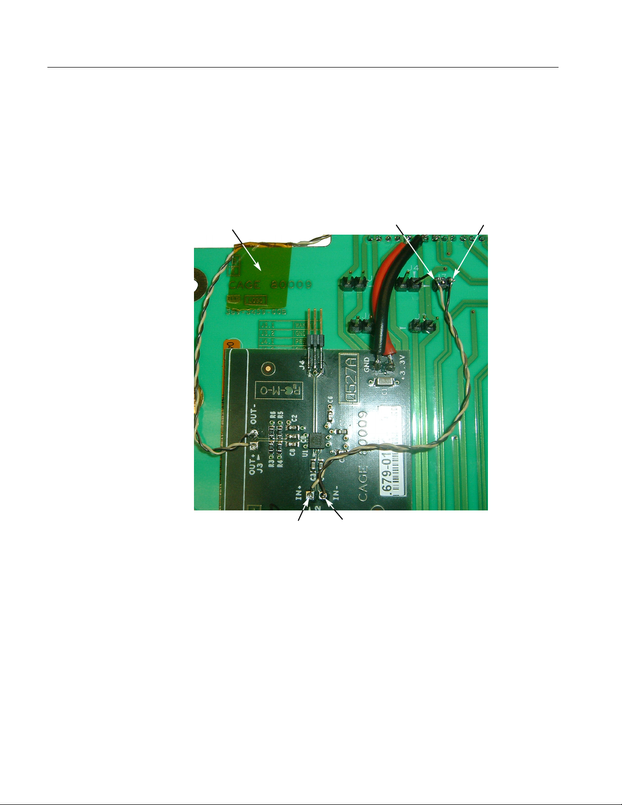
11. Solder the second brown twisted-pair wire from pin 1 of the J7 connector on
the Slot Adapter board to pin 1 of the J2 connector to the Interposer Fix
board. See Figure 10.
12. Solder the black twisted-pair wire from pin 3 of the J7 connector on the Slot
Adapter board to pin 2 of the J2 connector on the Interposer Fix board.
Tape
Pin1ofJ7
(brown wire)
Pin3ofJ7
(black wire)
12
Pin1ofJ2
(brown wire)
Pin2ofJ2
(black wire)
Figure 10: Slot Adapter board modification completed
13. (Optional) Using small strips of Kapton tape, tape the wires to the Slot
Adapter board to prevent the wires from snagging and coming loose.
PCI Express Slot Adapter Board Modification
Page 15

Verify Operation
Installation Instructions
NOTE. Connect the Slot Adapter board to the target system, but do not install the
PCI Express card.
Performing the following steps to verify instrument operation:
1. Power on the test platform. Use a differential probe and oscilloscope to
verify a 100 MHz reference clock across pins 1 and 3 of the J2 connector on
the Interposer Fix board.
2. Use a differential probe to verify a clean 100 MHz clock without steps on the
rising and falling edges across pins 1 and 3 of the J4 connector on the
Interposer Fix board.
3. Use a differential probe to verify a clean 100 MHz clock without steps on the
rising and falling edges across pins 13 and 14 of the J2 connector on the
back of the PCI Express Interposer board.
g End of document g
PCI Express Slot Adapter Board Modification
13
Page 16

Installation Instructions
14
PCI Express Slot Adapter Board Modification
 Loading...