

Page 1

Instructions
050-3591-00 or above
PC Interface Circuit Board Replacement Kit
TDS5000B Series
075-0834-00
Warning
The servicing instructions are for use by qualified
personnel only. To avoid personal injury, do not
perform any servicing unless you are qualified to
do so. Refer to all safety summaries prior to
performing service.
www.tektronix.com
*P075083400*
075083400
Page 2

Copyright © Tektronix, Inc. All rights reserved. Licensed software products are owned by Tektronix or its suppliers and
are protected by United States copyright laws and international treaty provisions.
Use, duplication, or disclosure by the Government is subject to restrictions as set forth in subparagraph (c)(1)(ii) of the
Rights in Technical Data and Computer Software clause at DFARS 252.227-7013, or subparagraphs (c)(1) and (2) of the
Commercial Computer Software -- Restricted Rights clause at FAR 52.227-19, as applica ble.
Tektronix products are covered by U.S. and foreign patents, issued and pending. Information in this publication supercedes
that in all previously published material. Spec ifications and price change privileges reserved.
Tektronix, Inc., P.O. Box 500, Beaverton, OR 97077
TEKTRONIX and TEK are registered trademarks of Tektronix, Inc.
Page 3

General Safety Summary
Review the following safety precautions to avoid injury and prevent damage to
this product or any products connected to it.
To avoid potential hazards, use this product only as specified.
Only qualified personnel should perform service procedures.
While using this product, you may need to access other parts of the system. Read
the General Safety Summary in other system manuals for warnings and cautions
related to operating the system.
ToAvoidFireor
Personal Injury
Use Proper Power Cord. Use only the power cord specified for this product and
certified for the country of use.
Connect and Disconnect Properly. Do not connect or disconnect probes or test
leads while they are connected to a voltage source.
Ground the Product. This product is grounded through the grounding conductor
of the power cord. To avoid electric shock, the grounding conductor must be
connected to earth ground. Before making connections to the input or output
terminals of the product, ensure that the product is properly grounded.
Observe All Terminal Ratings. To avoid fire or shock hazard, observe all ratings
and markings on the product. Consult the product manual for further ratings
information before making connections to the product.
Powering Off. The power cord provides Mains disconnect.
Do Not Operate Without Covers. Do not operate this product with covers or panels
removed.
Avoid Exposed Circuitry. Do not touch exposed connections and components
when power is present.
Do Not Operate With Suspected Failures. If you suspect there is damage to this
product, have it inspected by qualified service personnel.
Do Not Operate in Wet/Damp Conditions.
Do Not Operate in an Explosive Atmosphere.
Keep Product Surfaces Clean and Dry.
Provide Proper Ventilation. Refer to the manual’s installation instructions for
details on installing the product so it has proper ventilation.
PC Interface Circuit Board Replacement Kit
1
Page 4

General Safety Summary
Symbols and Terms
Terms in this Manual. These terms may appear in this manual:
WARNING. Warning statements identify conditions or practices that could result
in injury or loss of life.
CAUTION. Caution statements identify conditions or practices that could result in
damage to this product or other property.
Terms on the Product. These terms may appear on the product:
DANGER indicates an injury hazard immediately accessible as you read the
marking.
WARNING indicates an injury hazard not immediately accessible as you read the
marking.
CAUTION indicates a hazard to property including the product.
Symbols on the Product. The following symbols may appear on the product:
CAUTION
Refer to Manual
WARNING
High Voltage
Protective Ground
(Earth) Terminal
Standby
Chassis Ground
2
PC Interface Circuit Board Replacement Kit
Page 5

Service Safety Summary
Only qualified personnel should perform service procedures. Read this Service
Safety Summary and the General Safety Summary before performing any service
procedures.
Do Not Service Alone. Do not perform internal service or adjustments of this
product unless another person capable of rendering first aid and resuscitation is
present.
Disconnect Power. To avoid electric shock, switch off the instrument power, then
disconnect the power cord from the mains power.
Use Care When Servicing With Power On. Dangerous voltages or currents may
exist in this product. Disconnect power, remove battery (if applicable), and
disconnect test leads before removing protective panels, soldering, or replacing
components.
To avoid electric shock, do not touch exposed connections.
PC Interface Circuit Board Replacement Kit
3
Page 6

Service Safety Summary
4
PC Interface Circuit Board Replacement Kit
Page 7

Kit Description
Products
Kit Parts List
This kit provides the parts and instructions to replace the PC Interface circuit
board in a TDS5000B instrument. The new PC Interface circuit board requires a
new cable (provided in this kit) that connects the PC Interface board to the
Mother board. It also requires the correct operating system restore software
(provided in this kit).
This document supports Tektronix modification: ECO 1403
TDS5000B B010100 to B019999
Quantity Part number Description
1ea 671-5883-00 Circuit bd assy: PC Interface, wired
1 ea 174-4865-00 Cable assy: 4 Pin, P4, (PC Interface board to Mother
board)
1 ea 075-0834-XX Kit Instructions: PC Interface Circuit Board Replacement
(050-3591-00)
1ea 063-3693-01 TDS5000B Series Operating System Restore CD for INTEL
AshlandII Motherboard,V2.0.5
PC Interface Circuit Board Replacement Kit
5
Page 8

Kit Description
6
PC Interface Circuit Board Replacement Kit
Page 9

Installation Instructions
These instructions are for personnel who are familiar with servicing the product.
If you need further details for disassembling or reassembling the product, refer to
the appropriate product manual. Contact your nearest Tektronix, Inc., Service
Center or Tektronix Factory Service for installation assistance.
CAUTION. To avoid data loss, back up any important user files stored on the hard
disk to another media before continuing these instructions. The operating
system restoration process reformats the hard disk, which erases any userinstalled files and applications.
Minimum Tool and Equipment List
The following tools are required to perform this upgrade. All tools are standard
tools that are readily available.
Table 1: Tools required for module removal
Name Description
Screwdriver handle Accepts TorxR-driver bits
T-15 Torx tip Used for removing most oscilloscope screws.
TorxR-driver bit for T-15 size screw heads
T-20 Torx tip Used for removing carrying handle.
TorxR-driver bit for T-20 size screw heads
1
/
inch flat-bladed screwdriver
8
9
/
inch nut driver
32
3
/
inch nut driver
16
Screwdriver for unlocking cable connectors
Used to remove the GPIB nut posts
Used to remove the VGA connector nut posts
CAUTION. To prevent static discharge damage, service the product only in a
static-free environment. Observe standard handling precautions for static-sensitive devices while installing this kit. Always wear a grounded wrist strap,
grounded foot strap, and static resistant apparel while installing this kit.
PC Interface Circuit Board Replacement Kit
7
Page 10
Installation Instructions
Remove
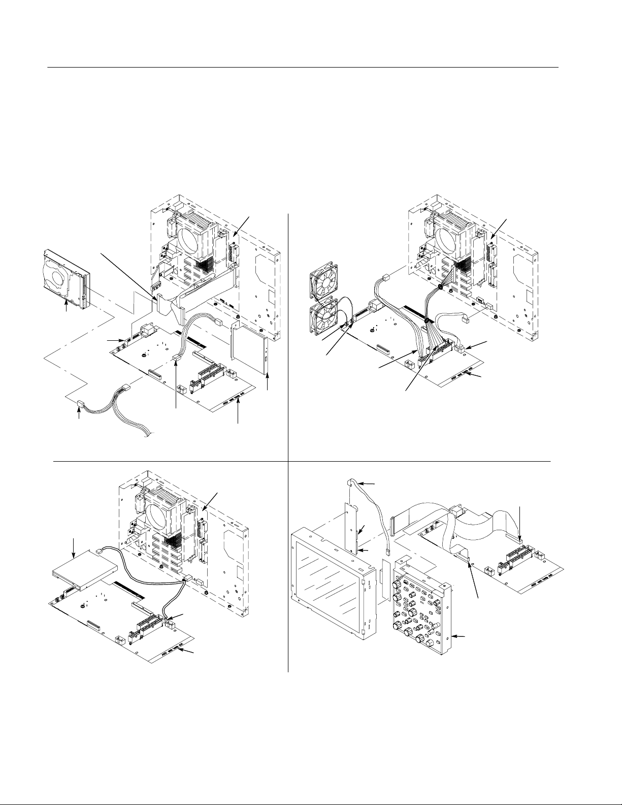
Figure 1 shows the location of cables and cable connectors for the PC Interface
board and the Mother board. Pay close attention to this diagram and the cable
connections when you disassemble and reassemble the instrument.
HD and
CDRW cables
Hard drive
GPIB
J1600
J510/CDRW drive
power cable
J510/CDRW drive
power cable
From power
supply
Mother board
Mother board
PC Interface
board
CDRW
drive
J1070
J1060
J1401/CPU
power cable
J1040/Power
supply cable
Inverter
adapter cable
Mother board
J520 Front
panel I/O
PC Interface
board
J510/Front panel
PWR cable
Floppy disk
drive
J1000/Dual
USB cable
PC Interface
board
Figure 1: PC Interface board and Mother board cable connections
8
J3
J2
J1010/Front
panel cable
Front panel
assembly
PC Interface Circuit Board Replacement Kit
Page 11

Installation Instructions
WARNING. Before doing any of the following procedures, disconnect the power
cord from the line voltage source. Failure to do so could cause serious injury or
death.
To access the PC Interface board complete the following procedures in the order
presented:
H Line cord
H Trim and carrying handle
H Bottom covers
H Right-side cover
H Floppy disk drive assembly
Line Cord
Trim and Carrying Handle
H Hard drive assembly
H CDRW drive assembly
H Power supply
H Mother board assembly
Disconnect the line cord from the AC power connector on the oscilloscope.
1. Locate the trim in the locator diagram. See Figure 4, page 12.
2. Remove the right side panel: Use Figure 4, page 12 as a guide.
a. Remove the CD Drive trim by inserting a flat blade screwdriver in the
bottom slot of the CD trim and gently prying the trim piece out of the
side panel. Pull the trim up and out from the oscilloscope.
b. Remove the two T-15 Torxdrive screws that secure the right side panel to
the bottom of the instrument. Slide the right side panel towards the rear
of the oscilloscope allowing the tabs to clear the cover openings, then
pull out to remove the panel from the oscilloscope.
3. Remove the carrying handle and the left side panel: UseFigure4,page12as
a guide.
a. Remove the two T-20 Torxdrive screws that secure the handle to the
oscilloscope. Remove the handle from the oscilloscope.
b. Remove the two T-15 Torxdrive screws that secure the left side panel to
the bottom of the instrument. Slide the left side panel towards the rear of
PC Interface Circuit Board Replacement Kit
9
Page 12

Installation Instructions
the oscilloscope allowing the tabs to clear the cover openings, then pull
out to remove the panel from the oscilloscope.
4. Remove the VGA panel: Remove the VGA panel by gently pulling the trim
up and out from the oscilloscope. Refer to Figure 4, page 12 as a guide.
5. Remove the top cover: Use Figure 4, page 12 as a guide.
a. Remove the accessory tray door or printer door and pull the door straight
up to remove it from the hinge.
b. Remove the accessory tray or internal printer (two T-15 Torxdrive
screws). See Figure 2, on page 10.
T-15 Torx
screw (2)
Printer
Figure 2: Printer screw mounting
c. If the internal printer is installed, disconnect the cable from the printer.
SeeFigure3.
d. Remove the feet from the top rear of the oscilloscope by removing the
two T-15 Torxdrive screws.
e. Slide the top cover towards the rear of the oscilloscope allowing the tabs
to clear the cover openings, then pull out to remove the cover from the
oscilloscope.
10
PC Interface Circuit Board Replacement Kit
Page 13

Printer
Installation Instructions
Printer connector
Printer cable
Figure 3: Printer cable connection
6. Remove the front panel and acquisition trim:
a. To prevent the power button from falling out of the front panel trim,
place a piece of tape over the button.
b. Remove the three T-15 Torxdrive screws that secure the front panel trim
to the bottom of the instrument.
c. Grasp the trim ring by its top edge and pull toward you to detach the
three plastic snaps. (Alternatively, you can use a flat-bladed solder aid or
other small prying tool to help you detach the snaps.)
d. Grasp the trim ring by its side edges and slide it back and forth to release
the snap in the middle of the trim ring. The snap is at the bottom “T” of
the front panel above the channel 1 and 2 BNCs.
e. Pull off the trim ring. As you do so, take care not to lose the 3 pem
inserts in the bottom of the trim ring.
f. Remove the acquisition trim from the oscilloscope. Use Figure 4,
on page 12 as a guide.
PC Interface Circuit Board Replacement Kit
11
Page 14

Installation Instructions
T-15 Torxdrive
screw (2)
Accessory tray
T-20 Torxdrive
screw (2)
Accessory
tray door
Top cover trim
Left side
panel
T-15 Torxdrive
screw (2)
Front panel trim
Carrying handle
Acquisition trim
Pem
inset (3)
T-15 Torxdrive
screw (4)
VGA panel
Power cord
retainer (4)
Right side
panel
CD-drive trim
T-15 Torxdrive
screw (2)
Figure 4: Trim removal
12
T-15 Torxdrive
screw (3)
Front panel cover
PC Interface Circuit Board Replacement Kit
Page 15

Installation Instructions
Bottom Covers
1. Remove the bottom covers: SeeFigure5.
2. Orient the oscilloscope: Set the oscilloscope so the top is down on the work
surface and the bottom is facing you.
a. Remove the two T-15 Torxdrive screws that secure the bottom cosmetic
cover to the oscilloscope, and remove the cover.
b. Remove the seven T-15 Torxdrive screws that secure the bottom metal
cover to the oscilloscope, and remove the cover.
Figure 5: Bottom cover removal
Bottom metal
cover
T-15 Torxdrive
screw (4)
Bottom cosmetic
cover
T-15 Black oxide Torxdrive
screws (5). Note: Be sure to
reinstall these screws here.
PC Interface Circuit Board Replacement Kit
13
Page 16

Installation Instructions
Right-Side Cover
1. Remove the right-side cover: See Figure 6.
2. Orient the oscilloscope: Set the oscilloscope on the work surface with the
front of the oscilloscope facing you.
NOTE. All mounting screw holes are indicated by a star etched around the
mounting hole. Some of the screws have different lengths; note the length of the
screws when you remove them to ensure you reinstall them correctly.
3. Remove the 15 T-15 Torxdrive screws that secure the right-side cover to the
top and right sides of the chassis. See Figure 6.
4. Remove the right-side cover (and printer tray, if installed).
CAUTION. Take care not to bind or snag the covers on the oscilloscope internal
cabling as you remove or install.
Tab
T-15 Torxdrive
screw (15)
14
Right side cover
Figure 6: Right-side cover removal
PC Interface Circuit Board Replacement Kit
Page 17

Installation Instructions
Floppy Disk Drive
Assembly
1. Set the oscilloscope so the bottom is down on the work surface and the front
panel is facing you.
2. Use Figure 7 as a guide and remove the cable from the back of the floppy
disk drive.
3. Remove the two T-15 Torxdrive screws that secure the floppy disk drive
assembly to the chassis.
4. Set the assembly aside on a static-free surface.
Floppy drive cable
T-15 Torx
screw (2)
Figure 7: Floppy disk drive assembly removal
PC Interface Circuit Board Replacement Kit
15
Page 18

Installation Instructions
Hard Disk Drive Assembly
1. Set the oscilloscope so the bottom is down on the work surface and the right
side panel is facing you.
2. Remove the 2 T-15 Torx screws that secure the Hard Disk Drive assembly to
the chassis.
3. Pull the Hard Disk Drive assembly away from the chassis far enough to
access the cables.
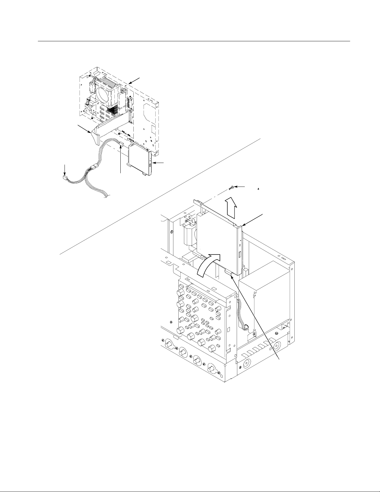
4. Disconnect the 2 cables from the Hard Disk Drive assembly. See Figure 8.
5. Remove the Hard Disk Drive assembly and set it aside on a static-free
surface.
Mother board
assembly
Disconnect from
the hard drive
Hard drive
CDRW Disk Drive
Assembly
To
CDRW
drive
Disconnect from
the hard drive
From power
supply
Figure 8: Desktop hard drive removal
1. Remove the T-15 Torxdrive screw that secures the CDRW Disk Drive
assembly to the chassis.
2. Pull the CDRW Disk Drive assembly away from the chassis far enough to
disconnect the cables. See Figure 9.
3. Remove the CDRW Drive from the assembly and set it aside on a static-free
surface.
16
PC Interface Circuit Board Replacement Kit
Page 19
Disconnect from
the CDRW drive
assembly
To hard
drive
Disconnect from
the CDRW drive
assembly
From power
supply
Installation Instructions
Mother board
assembly
CDRW drive
assembly
T-15 Torxdrive
screw (1)
CDRW drive
assembly
Figure 9: CDRW drive assembly removal
PC Interface Circuit Board Replacement Kit
Tab ( 2)
17
Page 20

Installation Instructions
Power Supply
1. Set the oscilloscope so the bottom is down on the work surface and the back
is facing you.
2. Remove the four T-15 Torxdrive screws that secure the power supply to the
back of the chassis. See Figure 10.
3. Remove the T-15 Torxdrive screw that secures the power supply to the right
side of the chassis.
4. Move the power supply towards the back of the instrument to access the
cables and unplug the two power supply cables from the PC Interface board.
5. Lift the power supply away from the chassis and guide the cables out.
T-15 Torxdrive
screw (4)
Disconnect from the
PC Interface board
Figure 10: Power supply removal
Power supply
Right side of
the instrument
T-15 Torxdrive
screw (1)
Disconnect from the
PC Interface board
18
PC Interface Circuit Board Replacement Kit
Page 21

Installation Instructions
Mother board Assembly
1. Set the oscilloscope so the bottom is down on the work surface and the top
panel is facing you.
NOTE. The Mother board and rear chassis are removed as one assembly.
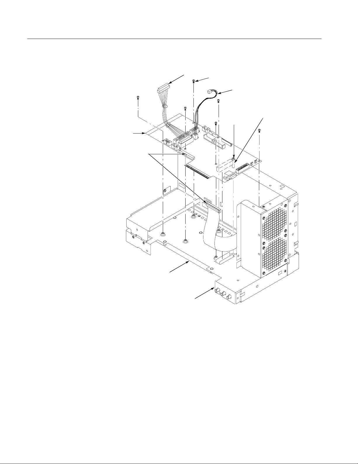
2. Remove the Mother board assembly: See Figure 11, on page 20.
a. Remove the two jack screws that secure the VGA connector to the
bracket.
b. Remove the single T-15 Torxdrive screw that secures the VGA bracket to
the chassis.
NOTE. Note the location of the cables and connectors on the Mother board
before removing them. This will make it easier to connect them properly. If
necessary, refer to Figure 1 on page 8 to determine the correct locations of the
cables.
c. Disconnect the hard disk drive and CDRW drive ribbon cables from the
Mother board assembly.
d. Disconnect the 4--wire cable and the 20-wire cable from the Mother
board assembly to the PC Interface board.
e. Disconnect the GPIB cable from the PC Interface board.
f. Remove the eight T-15 Torxdrive screws that secure the Mother board
assembly to the main chassis.
g. Carefully lift the assembly part way out of the chassis.
h. Remove the VGA bracket and set it aside.
i. Disconnect the two cables at the bottom of the Mother board assembly.
j. Remove the Mother board assembly and set it aside on a static-free
surface.
PC Interface Circuit Board Replacement Kit
19
Page 22

Installation Instructions
Mother board
VGA bracket
Jack screw (2)
assembly
Pouch bracket
Power cord
retainer (4)
T-15 Torxdrive
screw (4)
T-15 Torxdrive
screw (9)
Front of the
instrument
Rear View
Front View
Mother board
assembly
Disconnect from the
PC Interface board
Disconnect from
the Mother board
Figure 11: Mother board removal
20
T-15 Torxdrive
screw (6)
Disconnect
from the
Mother board
Mother board
PC Interface Circuit Board Replacement Kit
Page 23
Installation Instructions
PC Interface Board
1. Set the oscilloscope so the bottom is down on the work surface and the top
panel is facing you.
2. Remove the PC Interface board: See Figure 12, on page 22.
a. Disconnect the ribbon cables at J510, J1010, and J1090 from the PC
Interface board to the front panel, display, and printer (if installed).
NOTE. Note the location of the cables and connectors on the PC Interface board
before removing them. This will make it easier to connect them properly. If
necessary, refer to Figure 1 on page 8 to determine the correct locations of the
cables.
b. Disconnect the two fan cables from the PC Interface board.
c. Remove the ribbon cable at J520 and the split cable at J1000 from the
PC Interface board.
d. Remove the heavy-duty 20-wire cable from the PC Interface board at
J1040.
e. Remove and discard the white 4-wire cable from the PC Interface board
at J1044 (you will replace this cable with the new cable that came with
this kit).
f. Remove the six T-15 Torx screws that secure the PC Interface board to
the chassis.
CAUTION. Do not remove the screw next to J1800 (See Figure 12 on page 22).
The screw secures an indexing pin used to align the J1800 connectors together.
g. Grasp the PC Interface board near J1800 (see Figure 12) and carefully
pull the board up to disconnect J1800. Once you have cleared the
connector, remove the board from the chassis.
PC Interface Circuit Board Replacement Kit
21
Page 24
Installation Instructions
Disconnect from the
PC Interface board
T-15 Torx screw (6)
Disconnect and discard
Interface
board
Disconnect
from the PC
Interface board
Acquisition
board
Do not
remove
this screw!
Guide pin (located on
the back of the board)
Install
22
Back of the
instrument
Figure 12: PC Interface board removal
The installation procedures are done in reverse order of the removal procedures.
Refer to Figure 1 on page 8 for the location of cables and cable connectors for
the PC Interface board and the Mother board.
PC Interface Circuit Board Replacement Kit
Page 25

Installation Instructions
1. Remove the new PC Interface board from the kit packaging.
2. Set the board in place and align the J1800 halves using the guide pin. Gently
press the board into place to seat the connector between the PC Interface
board and the acquisition board.
3. Install the six T-15 Torx screws that secure the PC Interface board to the
chassis.
CAUTION. Use only the 4-wire (yellow and black) cable that came with this kit
with the new PC Interface board. Using the old (white) 4-wire cable will damage
the instrument when you apply power.
4. Connect the new 4-wire cable to the PC Interface board at J1044.
5. Reconnect all other cables to the PC Interface board (see Figure 1 on page 8
and Figure 12 on page 22 as necessary to reinstall all the cables to the PC
Interface board).
6. Orient the Mother board assembly so the bottom is down on the work
surface and the connector panel is facing you.
7. Follow the steps 2a through 2j under Mother board Assembly on page 19 in
reverse order to reconnect all cables on the Mother board and to install the
Mother board assembly in the chassis. If necessary, refer to Figure 1 on
page 8 and Figure 11 on page 20 to reinstall all the cables.
8. Reinstall the power supply.
9. Reinstall the CDRW Disk Drive Assembly, Hard Disk Drive assembly, and
Floppy Disk Drive assembly. Refer to the individual removal procedures as
necessary.
10. Reinstall the right-side cover (and printer tray).
11. Reinstall the bottom covers.
12. Reinstall the front panel and acquisition trim, top cover, printer, VGA panel,
left side panel and carrying handle, and the right side trim.
PC Interface Circuit Board Replacement Kit
23
Page 26

Installation Instructions
Install the Operating System Software
After you reassemble the instrument, you need to install the software that
support the new hardware. Use the following procedure to install the software:
1. Install the TDS5000B Operating System Restore CD that came with this kit.
Follow the instructions provided with the CD.
2. Install the TDS5000B Series Product software CD that came with your
original instrument. Follow the instructions provided with the CD.
3. Install any Optional Application software on Windows based Oscilloscopes
CD. Follow the instructions provided with the CD.
4. Install any software that you may have backed up prior to installing this
upgrade kit.
g End of document g
24
PC Interface Circuit Board Replacement Kit
 Loading...