

Page 1

Instructions
050-3571-03 and Above
TLA714, TLA715, TLA720, and TLA721
CD-RW Drive Replacement Kit
075-0795-03
Warning
The servicing instructions are for use by qualified
personnel only. To avoid personal injury, do not
perform any servicing unless you are qualified to
do so. Refer to all safety summaries prior to
performing service.
www.tektronix.com
*P075079503*
075079503
Page 2

Copyright © Tektronix, Inc. All rights reserved. Licensed software products are owned by Tektronix or its subsidiari es or
suppliers, and are protected by national copyright laws and international treaty provisions.
Tektronix products are covered by U.S. and foreign patents, issued and pending. Information in this publication supercedes
that in all previously published material. Specifica tions and price change privileges reserved.
TEKTRONIX and TEK are registered trademarks of Tektronix, Inc.
Contacting Tektronix
Tektronix, Inc.
14200 SW Karl Braun Drive
P.O. Box 500
Beaverton, OR 97077
USA
For product information, sales, service, and technical support:
H In North America, call 1-800-833-9200.
H Worldwide, visit www.tektronix.com to find contacts in your area.
Page 3

Service Safety Summary
Only qualified personnel should perform service procedures. Read this Service
Safety Summary and the General Safety Summary in the product service manual
or the instruction manual.
Do Not Service Alone. Do not perform internal service or adjustments of this
product unless another person capable of rendering first aid and resuscitation is
present.
Disconnect Power. To avoid electric shock, switch off the instrument power, then
disconnect the power cord from the mains power.
Use Care When Servicing With Power On. Dangerous voltages or currents may
exist in this product. Disconnect power, remove battery (if applicable), and
disconnect test leads before removing protective panels, soldering, or replacing
components.
To avoid electric shock, do not touch exposed connections.
CD-RW Replacement Instructions
1
Page 4

Service Safety Summary
2
CD-RW Replacement Instructions
Page 5

Kit Description
This kit provides parts and instructions to replace the CD-RW drive for your
TLA714, TLA715, TLA720, and TLA721 logic analyzer mainframes. This kit is
not available for the TLA704 or TLA711 logic analyzer mainframes.
This document supports Tektronix modification: 564, 685, ECR 30450, and
ECR 30766.
Products
TLA714 Portable Mainframe All serial numbers
TLA715 Portable Mainframe All serial numbers
TLA720 Benchtop Mainframe All serial numbers
TLA721 Benchtop Mainframe All serial numbers
Minimum Tool and Equipment List
Required tools and equipment Part number or Description
Screwdriver handle Accepts TorxR-driver bits
T-10 Torx tip Used for removing most of the T-10 size screw
heads on the TLA720 and TLA721 controllers
T-15 Torx tip Used for removing most or t he TLA714 or
TLA715 instrument’s screws. TorxR-driver bit for
T-15 size screw heads
#1 Phillips screwdriver Screwdriver for removing small Phillips screws
#0 Phillips screwdriver with 6-inch shaft Screwdriver for removing small Phillips screws
on the CD-ROM drive
Nut driver A3/16-inch nut driver used for removing controller
front panel hardware
Nut driver A1/4-inch nut driver used for removing nuts on
the back side of the controller front panel
Flat blade screwdriver Small flat blade screwdriver for removing
controller front panel hardware
Spudger tool for removing TLA714 or
TLA715 Trim Ring
Tektronix part number: 003-0008-00
CD-RW Replacement Instructions
3
Page 6

Kit Description
Kit Parts List
Quantity Part number Description
1 ea. 063-3666-xx Software package, Click’N Burn software patch
1 ea. 065-0666-xx Disk Drive; Optical; CD-W224E-A93 CD-RW and packaging
1 ea. 075-0795-03 Instructions, 050-3571-xx CD-RW Drive Replacement
4
CD-RW Replacement Instructions
Page 7

Installation Instructions
WARNING. These servicing instructions are for use by qualified personnel only.
To avoid personal injury, do not perform any servicing unless you are qualified
to do so. Refer to all safety summaries prior to performing service.
These instructions assume that you are familiar with servicing the instrument. If
you need further details for disassembling or reassembling the instrument, refer
to one of the following service manuals:
H TLA714 Portable Mainframe Service Manual (071-0267-xx)
H TLA715 Portable Mainframe Service Manual (071-0913-xx)
H TLA720 Benchtop Controller Service Manual (071-0269-xx)
H TLA721 Benchtop & TLA7XM Expansion Mainframe Service Manual
(071-0912-xx)
You may also contact your nearest Tektronix service center for installation
assistance.
CAUTION. To prevent static discharge damage, service the product only in a
static-free environment. Observe standard handling precautions for static-sensitive devices while installing this kit. Always wear a grounded wrist strap,
grounded foot strap, and static resistant apparel while installing this kit.
WARNING. To prevent serious injury or death, power off the instrument with the
On/Standby switch, and disconnect the power cord from the AC power connector.
Mainframe Specific Instructions
If you are installing the CD-RW drive in a TLA714 or TLA715 portable logic
analyzer mainframe, follow the instructions under TLA714 and TLA715 CD-RW
Drive Instructions beginning on page 6.
If you are installing the CD-RW drive in a TLA720 Benchtop Controller follow
the instructions under TLA720 CD-RW Drive Instructions beginning on page 10.
CD-RW Replacement Instructions
5
Page 8

Installation Instructions
If you are installing the CD-RW drive in a TLA721 Benchtop Controller follow
the instructions under TLA721 CD-RW Drive Instructions beginning on page 18.
TLA714 and TLA715 CD-RW Drive Instructions
This section contains procedures for replacing the CD-RW drive in the TLA714
or TLA715 portable mainframe. The instructions for the TLA714 and TLA715
are similar and differences between the two products are called out as necessary.
These instructions require that you be familiar with servicing the instrument. If
you are not familiar with servicing the instrument, you are strongly recommended to contact your nearest Tektronix service representative.
Remove the Replaceable
Hard Disk Drive
Remove the Accessories
Pouch
Remove the Trim Ring
Complete the following steps to remove the replaceable hard disk drive from the
mainframe. Always remove the hard disk drive before accessing any of the
replaceable components in the instrument.
CAUTION. Do not remove the replaceable hard disk drive while the instrument is
powered on. You can permanently damage the replaceable hard disk drive if you
remove it while the instrument is powered on. Always power down the mainframe before removing the replaceable hard disk drive.
1. Power down the instrument and disconnect the power cord.
2. Press the latch on the side of the instrument to unlatch the hard disk drive.
3. Remove the hard disk drive from the instrument by pulling on the handle.
The accessories pouch is held in place on the top cover by snaps. Gently lift up
on each corner of the pouch until the pouch snaps free from the top cover.
1. Set the mainframe with the cord-wrap feet on the work surface and the
bottom facing you.
2. Use the spudger tool to detach the three plastic snaps from the bottom cover
(see Figure 1). Then, swing the bottom of the ring upward and work the rest
of the ring off the front panel.
6
CD-RW Replacement Instructions
Page 9

Trim ring
Installation Instructions
When removing the trim ring,
grasp its bottom edge and flex it
toward you before pulling upward.
Remove the Flat Panel
Display Assembly
CD-RW Replacement Instructions
Figure 1: Trim ring removal
1. Remove the five screws that attach the flat panel display assembly to the
mainframe (See Figure 2).
2. Lift the bottom edge of the flat panel display assembly and rotate it upward
and off the front face of the instrument.
3. Detach the ribbon cable connecting the flat panel display assembly to the
front panel interface board.
4. Detach the five-pin display backlight power connector and then set the
assembly aside.
7
Page 10

Installation Instructions
Remove screws (5)
Flat panel display
assembly
Disconnect
the cable
Remove the Front Panel
Control Assembly
Display
backlight
cable
Figure 2: Flat panel display assembly r emoval
1. Disconnect the cable at J102 on the front panel interface board.
2. Remove the four screws that attach the front panel control assembly to the
mainframe (See Figure 3).
3. Lift the bottom edge of the front control panel assembly and rotate it up and
off the front face of the mainframe.
4. Detach the ribbon cable connecting the CD-RW drive to the interface board.
8
CD-RW Replacement Instructions
Page 11

Installation Instructions
Remove 2 short screws
Replace the CD-RW Drive
Disconnect
the cable
Remove 2 short
screws
Front panel control
assembly
Disconnect
the cable
Figure 3: Front-panel control assembly removal
The CD-RW drive is attached to the underside of the front panel control
assembly.
1. Remove the four screws that attach the CD-RW drive to the front panel
control assembly and then separate the CD-RW drive from the front panel
assembly.
2. Remove the small Phillips screws that hold the CD-RW drive to the bracket
and then slide the CD-RW drive out of the bracket.
3. Disconnect the interface board from the old CD-RW drive and attach it to the
new drive.
CD-RW Replacement Instructions
9
Page 12

Installation Instructions
4. Install the new CD-RW drive in the bracket.
5. Install the small Phillips screws that hold the CD-RW drive to the bracket
and tighten the screws to 4 in-lbs.
6. Install the CD-RW drive assembly on the back of the front panel control
assembly.
7. Install the four screws and tighten the screws to 8 in-lbs.
Reinstallation
Verify Operation
Complete the removal instructions in reverse order to reassemble the instrument.
Go to page 24 and follow the instructions to verify the operation and (if
necessary) install the software.
TLA720 CD -RW Drive Instructions
This section contains procedures for replacing the CD-RW drive in the TLA720
Benchtop controller.
These instructions require that you be familiar with servicing the instrument
because of the complexity of the Controller subassembly. If you are not familiar
with servicing the instrument, you are strongly recommended to contact your
nearest Tektronix service representative for installation information.
CAUTION. Do not remove the replaceable hard disk drive or any modules while
the mainframe is powered on. You can permanently damage the mainframe if you
remove the hard disk drive or modules while the mainframe is powered on.
Remove the Replaceable
Hard Disk Drive
Remove the Benchtop
Controller
10
1. Power down the instrument and disconnect the power cord.
2. Press the latch on the side of the instrument to unlatch the hard disk drive.
3. Remove the hard disk drive from the instrument by pulling on the handle.
1. If you have not already done so, power down the mainframe and disconnect
the power cord.
2. Loosen the screws that secure the controller to the mainframe.
3. Disengage the benchtop controller from the mainframe using the injector/
ejector handles.
CD-RW Replacement Instructions
Page 13

Installation Instructions
4. Remove the controller from the mainframe and place it on a static-free work
surface.
Remove the Benchtop
Controller Covers
Remove the T-10 Torx-drive screws shown in Figure 4 and then remove the
module and rear panel the covers.
Module cover
Remove screws*
CD-RW Replacement Instructions
Chassis
Note:* Older TLA720 controllers have eight (8) screws that hold the cover in place. Newer TLA720
controllers have ten (10) screws similar to the TLA721 controllers in Figure 10 on page 20.
Figure 4: Removing the covers from the controller
11
Page 14

Installation Instructions
NOTE. Earlier versions of the TLA720 Benchtop Controllers had two separate
brackets for mounting the CD-RW drive. Later versions had a single bracket. If
your benchtop controller has the two piece mounting bracket, continue with the
following steps. If your benchtop controller has the single piece bracket, follow
the instructions beginning on page 14 to remove the CD-RW drive.
Install the CD-RW Drive
(Older TLA720 Benchtop
Controllers)
Complete the following steps to replace the CD-RW drive in older TLA720
Benchtop Controllers.
The CD-RW drive is located on the hard drive interface board. You can remove
the CD-RW drive and the brackets without removing the hard drive interface
board.
Remove the CD-RW Drive. Complete the following steps to remove the CD-RW
drive and the mounting brackets:
1. Using a #0 Phillips head screwdriver with a 6-inch long shaft, remove the
two screws on the side of the CD drive bracket by reaching through one of
the holes in the chassis as shown in Figure 5.
2. Remove the two screws on the other side of the CD drive bracket by
reaching through one of the holes of the chassis.
12
CD-RW Replacement Instructions
Page 15

Remove
screws
Installation Instructions
Figure 5: Remove screws from the CD drive bracket
3. Slide the CD-RW drive out of the bracket.
4. Disconnect the ribbon cable and the small interface board from the CD-RW
drive. Leave the other end connected to the hard drive interface board.
Install the CD-RW Drive. Complete the following steps to install the new CD-RW
drive.
1. Connect the small interface board with the drive ribbon cable to the CD-RW
drive. Verify that pin-1 of the cable is connected to pin-1 of the connector.
2. Slide the new CD-RW drive into the bracket until the front of the drive is
flush with the front panel.
3. Attach the CD-RW drive to the bracket using the the four screws from the
removal process. (Use the long screw driver as necessary.)
4. Complete the instructions under Reinstall the Benchtop Controller Covers on
page 17.
CD-RW Replacement Instructions
13
Page 16
Installation Instructions
Install the CD-RW Drive
(Newer TLA720 Benchtop
Controllers)
Use the following procedures to install the CD-RW drive on newer TLA720
benchtop controllers. You will need to remove the front panel and the hard disk
drive interface board to access the CD mounting bracket.
Remove the Front Panel. You must remove the front panel and the injector
handles before you can access the hard disk drive interface board in the newer
benchtop controllers. You will need a screwdriver with a T-10 Torx tip, a
nut driver, a
3
/16-nut driver, and a small flat-blade screwdriver to complete the
1
/4-inch
procedure.
1. Place the controller on the right side and then remove the T-10 Torx screws
that secure the top and bottom handles to the chassis; remove the handles
and set them aside.
1
2. Remove the five
/4-inch nuts on the back of the front panel.
3. Using a small, flat-blade screw driver, remove the two screws from the
printer port connector on the front panel (see Figure 6).
3
4. Using the
/16-nut driver, remove the four jack screws from the video port
and the COM A port connectors.
5. Pull the front panel off so that you can access the flat-head T -10 screws
underneath the front panel.
14
Nuts (5)
Jack screws (4)
Screws (2)
Figure 6: Removing the front panel hardware
CD-RW Replacement Instructions
Page 17

Hard disk drive
interface board
Installation Instructions
Remove the Hard Disk Drive Interface Boar d. Complete the following steps to
remove the hard disk drive interface board from the chassis:
1. Refer to Figure 7 and remove the four T-10 screws from the front of the
controller.
2. Remove the four flat-head T-10 screws on the chassis that hold the hard
drive interface board in place. See Figure 7.
3. Disconnect the two ribbon cables located on the rear of the hard disk
interface board.
4. Slide the hard disk drive interface board out of the chassis.
Remove screws (4)
Figure 7: Removing the hard disk drive interface board from the chassis
CD-RW Replacement Instructions
Disconnect
cables
Remove screws (4)
15
Page 18

Installation Instructions
Replace the CD-RW Drive. Complete the following steps to replace the CD-RW
drive:
1. Disconnect the small interface board and ribbon cable at the rear of the
CD-RW drive from the the hard disk drive interface board.
2. Using a #0 Phillips head screwdriver, remove the four screws on the sides of
the CD bracket and remove the CD-RW drive assembly from the bracket.
3. Disconnect the interface board and ribbon cable from the old CD-RW drive.
4. Connect the interface board with the ribbon cable to the new CD-RW drive.
5. Slide the CD-RW drive into the bracket.
6. Attach the CD-RW drive to the bracket using the four screws that you
removed earlier. Tighten the screws to 1 in-lbs.
7. Connect the ribbon cable from the small interface board at the rear of the
CD-RW drive to the hard disk drive interface board.
Install the Hard Disk Drive Interface Board and Front Panel. Complete the
following steps to install the hard disk drive interface board and front panel.
1. Install the hard disk drive interface board in the chassis making sure that the
CD-RW drive fits into the opening at the front of the chassis.
2. Install the four flat-head T-10 screws on the top and bottom of the chassis;
tighten the screws to 4 in-lbs (refer to F igure 7 on page 15 as necessary).
3. Connect the two ribbon cables from the processor board to the hard disk
drive interface board.
4. Install the four flat-head T-10 screws on the front of the chassis; tighten the
screws to 4 in-lbs.
5. Secure the front panel in place by lining up the five studs on the front panel
1
with the holes on the front of the chassis. Install and tighten the five
/4-inch
nuts on the back of the front panel to 4 in-lbs.
6. Using the
3
/16-nut driver, install the four jack screws to the video port and to
the COM A port connectors. Tighten the jack screws to 3 in-lbs.
7. Install the two screws on the printer port connector using a small, flat-blade
screw driver.
16
NOTE. The top and bottom ejector handles are not interchangeable.
8. Install the ejector handles through the front panel cutouts onto the mounting
posts and then install the screws to secure the handles to the chassis.
CD-RW Replacement Instructions
Page 19

Installation Instructions
Reinstall the Benchtop
Controller Covers
1. Place the cover on the chassis. Push forward on the cover so the tab on the
front edge of the cover inserts into the rear of the front subpanel. Make sure
that the cover is fully seated, with no gaps, against the front and rear chassis
flanges (refer to Figure 8 on page 17 as necessary).
2. Install the rear panel cover.
3. Squeeze the sides together before tightening to ensure a good EMI seal and
mechanical connection.
Reinstall the Replaceable
Hard Disk
CD-RW Replacement Instructions
Make sure tab inserts into
slot on rear of front panel
Leave no vertical gap
Figure 8: Seating the cover on the chassis
Slide the hard disk assembly into the front panel. Push on the handle until it
latches in place.
17
Page 20

Installation Instructions
Install the Controller in the
Mainframe
Verify Operation
Slide the controller into the mainframe and latch it in place. Tighten the
controller hold-down screws.
Go to page 24 and follow the instructions to verify the operation and (if
necessary) install the software.
TLA721 CD -RW Drive Instructions
This section contains procedures for replacing the CD-RW drive in the TLA721
Benchtop controller.
These instructions require that you be familiar with servicing the instrument,
because of the complexity of the Controller subassembly. If you are not familiar
with servicing the instrument, you are strongly recommended to contact your
nearest Tektronix service representative for installation information.
CAUTION. Do not remove the replaceable hard disk drive or any modules while
the mainframe is powered on. You can permanently damage the mainframe if you
remove the hard disk drive or modules while the mainframe is powered on.
Remove the Replaceable
Hard Disk Drive
Remove the Benchtop
Controller
1. Power down the instrument and disconnect the power cord.
2. Press the latch on the side of the instrument to unlatch the hard disk drive.
3. Remove the hard disk drive from the instrument by pulling on the handle.
1. If you have not already done so, power down the mainframe and disconnect
the power cord.
2. Loosen the screws that secure the controller to the mainframe.
3. Disengage the benchtop controller from the mainframe using the ejector
handles.
4. Remove the controller from the mainframe and place it on a static-free work
surface.
18
CD-RW Replacement Instructions
Page 21

Installation Instructions
Remove the Ejector
Handles
You must remove the ejector handles to provide access to the front panel. The
front panel contains hardware that holds the hard disk drive interface board in
place.
Place the controller on the right side as shown in Figure 9. Remove the T-10
Torx screws that secure the handle to the chassis and then remove the handles.
Remove screws (4)
Figure 9: Removing the ejector handles
Ejector handles (2)
CD-RW Replacement Instructions
19
Page 22

Installation Instructions
Remove the Benchtop
Controller Covers
Remove the ten flat-head T-10 Torx-drive screws, shown in Figure 10, and lift
off the controller left and rear covers.
Left side cover
Screws (10)
Rear cover
Remove the Front Panel
and Hard Disk Drive
Interface Board
20
Chassis
Figure 10: Removing and installing the left and rear covers
You must remove the front panel and then the hard disk drive interface board
before you can access the CD-ROM drive in the benchtop controller. You will
need a screwdriver with a T-10 Torx tip, a
1
/4-inch nut driver, a3/16-nut driver,
and a small flat-blade screwdriver to complete the procedures.
CD-RW Replacement Instructions
Page 23

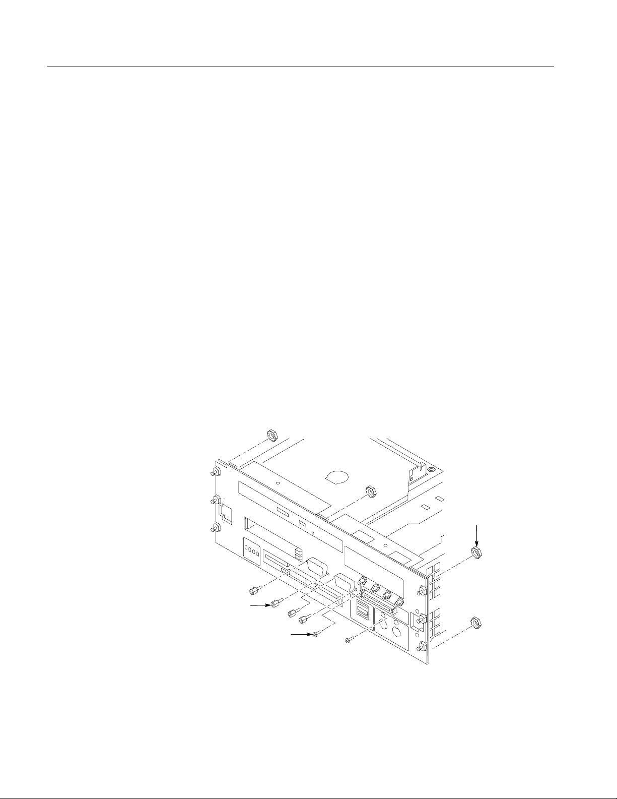
Installation Instructions
1. Remove the five
1
/4-inch nuts on the back of the front panel.
2. Using a small, flat-blade screw driver, remove the two screws from the
printer port connector on the front panel (see Figure 11).
3
3. Using the
/16-nut driver, remove the four jack screws from the two video
port connectors (do not remove the jack screws at the COM A connector).
4. Pull the front panel off so that you can access the flat-head T -10 screws
underneath the front panel (be careful so that you do not damage the cable
from the COM A connector).
Nuts (5)
Jack screws (4)
Screws (2)
Figure 11: Removing and installing the front panel hardware
5. Refer to Figure 12 and remove the four T-10 screws from the front of the
controller.
6. Remove the four flat-head T-10 screws on the bottom cover that hold the
hard drive interface board in place. See Figure 12.
7. Disconnect the two ribbon cables located on the rear of the hard disk
interface board.
8. Slide the hard drive interface board out of the chassis.
CD-RW Replacement Instructions
21
Page 24

Installation Instructions
Hard disk drive
interface board
Disconnect cable
Remove screws (4)
Figure 12: Removing screws from the front and sides of the controller
Replace the CD-RW Drive
1. Using a #0 Phillips head screwdriver, remove the four screws on the sides of
the CD-RW bracket (see Figure 13).
2. Remove the CD-RW drive assembly from the bracket.
3. Disconnect the interface board and ribbon cable from the CD-RW drive;
leave the other end of the ribbon cable connected to the hard disk drive
interface board.
Disconnect
cables
Remove screws (4)
22
CD-RW Replacement Instructions
Page 25

Ribbon
cable
Installation Instructions
CD ROM
CD-RW bracket
Screws (4)
Reinstallation
CD-RW Replacement Instructions
Screws (6)
Figure 13: Removing the CD-RW drive
4. Connect the small interface board with the drive ribbon cable to the new
CD-RW drive. Verify that pin-1 of the cable is connected to pin-1 of the
connector.
5. Slide the CD-RW drive into the new bracket.
6. Attach the CD-RW drive to the bracket using the the four screws from the
removal process. Tighten the screws to 1 in-lbs.
Complete the removal instructions in reverse order to reassemble the controller
module. Reinstall the module in the mainframe and latch it into place. Tighten
the controller hold-down screws.
23
Page 26

Installation Instructions
Verify Operation
1. After reassembling the instrument, reconnect the power cord and then power
on the instrument.
2. Verify that the instrument passes the power-on diagnostics.
3. Insert a CD in the CD-RW drive and then use Windows Explorer to verify
that you can view the contents of the CD.
4. If your instrument has Click’N Burn Pro software installed on the hard disk
drive, insert the floppy disk with the Click’N Burn software patch into the
floppy disk drive. Run PxEngineUpdate342.exe from the floppy disk and
follow the on-screen instructions to install the patch.
5. If your instrument has the RecordNow MAX software, do not install the
patch.
NOTE. The RecordNow MAX software is available with TLA Application
Software Version 4.3. You can order TLA7UP Option 32, which is a free upgrade
of the TLA application software. Or, depending on your PC controller, you can
purchase TLA7UP Option 31 or 33 (which includes Windows 2000 Professional
and the TLA application software with the RecordNow MAX software). Contact
your local Tektronix representative for ordering information.
6. If your instrument has the NERO software installed, do not install the patch.
g End of document g
24
CD-RW Replacement Instructions
 Loading...