

Page 1

Instructions
050-3534-00
Front Panel Board Replacement
CSA8000B and TDS8000B
075-0754-00
Warning
The servicing instructions are for use by qualified
personnel only. To avoid personal injury, do not
perform any servicing unless you are qualified to
do so. Refer to all safety summaries prior to
performing service.
www.tektronix.com
*P075075400*
075075400
Page 2

Copyright © Tektronix, Inc. All rights reserved. Licensed software products are owned by Tektronix or its subsidiaries or
suppliers, and are protected by national copyright laws and international treaty provisions.
Tektronix products are covered by U.S. and foreign patents, issued and pending. Information in this publication supercedes
that in all previously published material. Spec ifications and price change privileges reserved.
TEKTRONIX and TEK are registered trademarks of Tektronix, Inc.
Contacting Tektronix
Tektronix, Inc.
14200 SW Karl Braun Drive
P.O. Box 500
Beaverton, OR 97077
USA
For product information, sales, service, and technical support:
H In North America, call 1-800-833-9200.
H Worldwide, visit www.tektronix.com to find contacts in your area.
Page 3

General Safety Summary
Review the following safety precautions to avoid injury and prevent damage to
this product or any products connected to it. To avoid potential hazards, use this
product only as specified.
Only qualified personnel should perform service procedures.
While using this product, you may need to access other parts of the system. Read
the General Safety Summary in other system manuals for warnings and cautions
related to operating the system.
ToAvoidFireor
Personal Injury
Use Proper Power Cord. Use only the power cord specified for this product and
certified for the country of use. Power cord needed only in the mainframe, not
modules.
Connect and Disconnect Properly. Do not connect or disconnect probes or test
leads while they are connected to a voltage source.
Ground the Product. The mainframe is grounded through the grounding
conductor of the power cord. To avoid electric shock, the grounding conductor
must be connected to earth ground. Before making connections to the input or
output terminals of the product, ensure that the product is properly grounded.
Ground the Product. The modules are indirectly grounded through the grounding
conductor of the mainframe power cord. To avoid electric shock, the grounding
conductor must be connected to earth ground. Before making connections to the
input or output terminals of the product, ensure that the product is properly
grounded.
Observe All Terminal Ratings. To avoid fire or shock hazard, observe all ratings
and markings on the product. Consult the product manual for further ratings
information before making connections to the product.
Do not apply a potential to any terminal, including the common terminal, that
exceeds the maximum rating of that terminal.
Front Panel Board Replacement
Do Not Operate Without Covers. Do not operate this product with covers or panels
removed.
Use Proper Fuse. Use only the fuse type and rating specified for this product.
Avoid Exposed Circuitry. Do not touch exposed connections and components
when power is present.
Wear Eye Protection. Wear eye protection if exposure to high-intensity rays or
laser radiation exists.
Do Not Operate With Suspected Failures. If you suspect there is damage to this
product, have it inspected by qualified service personnel.
1
Page 4

General Safety Summary
Do Not Operate in Wet/Damp Conditions.
Do Not Operate in an Explosive Atmosphere.
Keep Product Surfaces Clean and Dry.
Provide Proper Ventilation. Refer to the manual’s installation instructions for
details on installing the product so it has proper ventilation.
Symbols and Terms
Terms in this Manual. These terms may appear in this manual:
WARNING. Warning statements identify conditions or practices that could result
in injury or loss of life.
CAUTION. Caution statements identify conditions or practices that could result in
damage to this product or other property.
Terms on the Product. These terms may appear on the product:
DANGER indicates an injury hazard immediately accessible as you read the
marking.
WARNING indicates an injury hazard not immediately accessible as you read the
marking.
CAUTION indicates a hazard to property including the product.
Symbols on the Product. The following symbols may appear on the product:
CAUTION
Refer to Manual
Mains Disconnected
OFF (Power)
WARNING
High Voltage
Mains Connected
ON (Power)
2
Protective Ground
(Earth) Terminal
Standby
Front Panel Board Replacement
Page 5

Service Safety Summary
Only qualified personnel should perform service procedures. Read this Service
Safety Summary and the General Safety Summary before performing any service
procedures.
Do Not Service Alone. Do not perform internal service or adjustments of this
product unless another person capable of rendering first aid and resuscitation is
present.
Disconnect Power. To avoid electric shock, switch off the instrument power, then
disconnect the power cord from the mains power.
Use Care When Servicing With Power On. Dangerous voltages or currents may
exist in this product. Disconnect power, remove battery (if applicable), and
disconnect test leads before removing protective panels, soldering, or replacing
components.
To avoid electric shock, do not touch exposed connections.
Front Panel Board Replacement
3
Page 6

Service Safety Summary
4
Front Panel Board Replacement
Page 7

Kit Description
Use these instructions to replace the front-panel board on the products listed in
the Products section of these instructions.
This document supports Tektronix modification: BV4441
Products
CSA8000B AllSerialNumbers
TDS8000B AllSerialNumbers
Minimum Tool and Equipment List
Required tools and equipment Part number
Screwdriver handle 620-440
T-15 Torx tip 640-247
1
/8inch flat-bladed screwdriver Standard tool
Kit Parts List
Angle-Tip Tweezers Standard tool
Quantity Part number Description
1 ea. 075-0754-00 KIT INSTRUCTIONS
1 ea. 671-4689-01 CIRCUIT BD ASSY; USB FRONT PANEL CONTROL BD
1 ea. 260-2724-01 SWITCH, KEYPAD; ELASTOMERIC, FRONT PANEL,
PUSHBUTTON
Front Panel Board Replacement
5
Page 8

Kit Description
6
Front Panel Board Replacement
Page 9

Installation Instructions
These instructions are for personnel who are familiar with servicing the product.
If you need further details for disassembling or reassembling the product, refer to
the appropriate product manual. Contact your nearest Tektronix, Inc., Service
Center or Tektronix Factory Service for installation assistance.
CAUTION. To prevent static discharge damage, service the product only in a
static-free environment. Observe standard handling precautions for static-sensitive devices while installing this kit. Always wear a grounded wrist strap,
grounded foot strap, and static resistant apparel while installing this kit.
Remove
Front-Panel Knobs
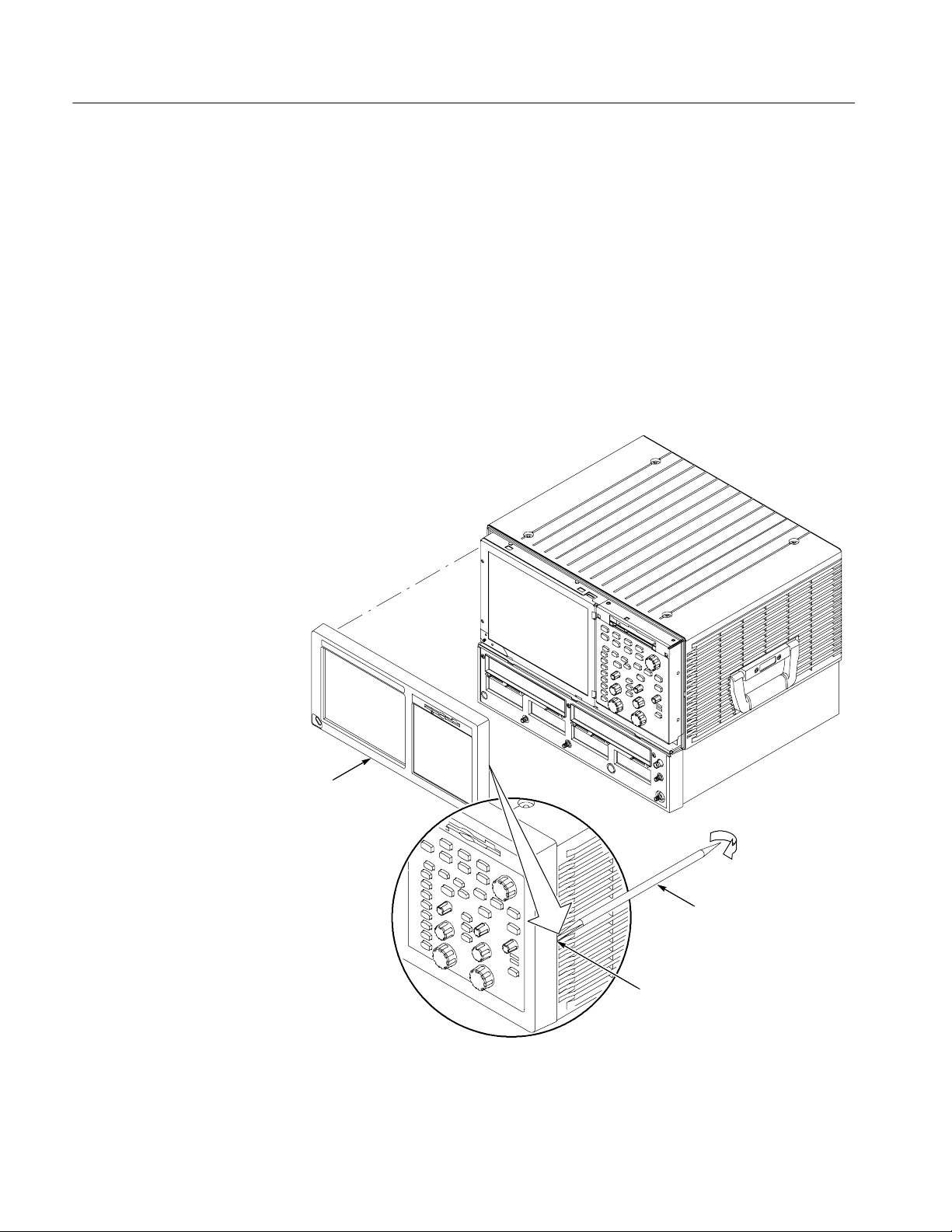
1. Assemble equipment and locate modules to be removed: Use an angled-tip
tweezers and locate the the front panel see Figure 2 on page 8.
2. Orient the instrument: Set the instrument so its bottom is down on the work
surface and its front is facing you.
3. Remove the knob(s): Grasp any knob you want to remove and pull it straight
out from the front panel about a
the base of the knob and the front panel. Insert the tweezers between the
knob and front panel and use them to remove the knob. See Figure 1.
1
/4inch to create some clearance between
Front Panel Board Replacement
Figure 1: Knob removal
7
Page 10
Installation Instructions
Trim
1. Locate module to be removed: Locate the Trim in the locator diagram, See
Figure2,page8.
2. Remove the front-panel trim: Use Figure 2, page 8, as a guide.
a. Place a piece of tape over the power button to prevent the button from
galling out of the front-panel trim.
b. Grasp the trim ring by its top edge and pull toward you to detach the
three plastic snaps. (Alternatively, you can use a flat-bladed screwdriver
or other small prying tool to help you detach the snaps.)
c. Swing the bottom of the ring upward and off the front panel.
Front panel trim
Soldering aid
To remove the trim ring, slide the flat
end of a soldering aid into the side
slot on the trim ring. Press in, then lift
up to hook it underneath, then pry
up.
Figure 2: Trim removal
8
Front Panel Board Replacement
Page 11

Installation Instructions
Front-Panel Assembly
1. Locate module to be removed: Locate the Front-panel assembly Figure 3,
page 9.
2. Remove the Front-panel assembly: SeeFigure3,page9.
3. Orient the instrument: Set the instrument so its bottom is down on the work
surface and its front panel is facing you.
a. Remove the six T-15 Torxdrive screws that secure the Front-panel
assembly to the front chassis.
b. Grasp the top of Front-panel assembly and pull forward to allow access
to the ribbon cable connector on the front panel board.
1
c. Use the
@8inch flat-bladed screwdriver to carefully lift J1 cable
connector lock up to disconnect J1 flex cable from the display module
assembly. See Figure 4, page 10. Note the connector’s pin 1 index mark
and the black stripe on the cable for later reassembly.
d. Pull the Front-panel assembly forward and remove from the instrument.
Floppy disk
support tab (2)
Chassis
slot (2)
J1 ribbon cable
Front-panel
assembly
Front-panel square
opening (2)
T--15 Torxdrive
screw (6)
Figure 3: Front-panel assembly removal
Front Panel Board Replacement
9
Page 12

Installation Instructions
Black stripe
toward connector
Screwdriver
Screwdriver
Front Panel Board
Front Panel Keypad
Figure 4: J1 flex cable connector removal
1. Locate module to be removed: Locate the Front panel assembly Figure 3,
page 9.
2. Remove the Front-panel board: See Figure 5, page 11.
a. Remove the eight T-15 Torxdrive screws that secure the Front-panel
board to the Front-panel assembly.
b. Pry the board up off the alignment studs. Place a flat bladed screwdriver
in the pry point access holes to pry the board up from the assembly.
c. Remove the board from the assembly.
1. Locate module to be removed: Locate the Front-panel assembly Figure 3,
page 9.
2. Remove the Front-panel keypad: SeeFigure5,page11.
10
Front Panel Board Replacement
Page 13

Installation Instructions
CAUTION. When removing or installing the keypad, make sure you do not touch
the switch contact with your fingers. The oils in your fingers will degrade or
damage the switch contacts. To help prevent damage to the keypad use cotton
gloves when removing or installing the keyboard pad.
a. Pull on each of the keypad support guides to separate the keypad from
the Front panel board. Use a pair of tweezers or equivalent tool to pull
the keypad support guides.
b. Remove the keypad from the front-panel board.
Alignment
stud
Keypad
Pry point
access hole
Keypad support
guide (9)
Front-panel board
T-15 Torxdrive
screw (8)
Install
Front Panel Board Replacement
Pry point access hole
Figure 5: Front panel board and keyboard r emoval
Use the following procedure to install your new Front-panel keypad to your new
front-panel board.
11
Page 14

Installation Instructions
Front-Panel Keypad
Reassemble
Install the Front-panel keypad: See Figure 5, page 11.
1. Carefully align the keypad on the Front-panel board.
2. Push on each of the keypad support guides to attach the keypad to the
Front-panel board.
CAUTION. When removing or installing the keypad, make sure you do not touch
the switch contacts with your fingers. The oils in your fingers will degrade or
damage the switch contacts. To help prevent damage to the keypad use cotton
gloves when removing or installing the keyboard pad.
1. To reinstall the Front-panel board (with keypad), do in reverse steps 2a
through c of Front-Panel Board on page 10. Note the following tips while
installing the front-panel.
H Make sure the keypad is aligned properly on the Front-panel board.
H Make sure the ribbon cable is routed correctly when installing the Front
-panel into the chassis.
H Insert the two floppy disk support tabs into the front panel square
openings. Both left front-panel tabs must go into the chassis slots. See
Figure 3, page 9.
2. To reinstall the Front-panel assembly, do in reverse steps 3a through d of
Front-Panel Assembly on page 9.
3. To install the trim, do in reverse steps 2a through c of Trim on page 8.
4. To reinstall the front-panel knobs, align each knob to the shaft and push it in
until it snaps.
CAUTION. To prevent damage to the encoders located onto the circuit board,
apply pressure to the backs of the encoders while pushing the knob on the shaft.
g End of document g
12
Front Panel Board Replacement
 Loading...