

Page 1

Instructions
020-2369-02
TLA72X, TLA7XM, & TLA7016
Benchtop Mainframe Rackmount Installation
071-0897-01
Warning
The servicing instructions are for use by qualified
personnel only. To avoid personal injury, do not
perform any servicing unless you are qualified to
do so. Refer to all safety summaries prior to
performing service.
www.tektronix.com
*P071089701*
071089701
Page 2

Copyright © Tektronix, Inc. All rights reserved. Licensed software products are owned by Tektronix or its subsidiaries or
suppliers, and are protected by national copyright laws and international treaty provisions.
Tektronix products are covered by U.S. and foreign patents, issued and pending. Information in this publication supercedes
that in all previously published material. Specifications and price change privileges reserved.
TEKTRONIX and TEK are registered tradem arks of Tektronix, Inc.
Contacting Tektronix
Tektronix, Inc.
14200 SW Karl Braun Drive
P.O. Box 500
Beaverton, OR 97077
USA
For product information, sales, service, and technical support:
H In North America, call 1-800-833-9200.
H Worldwide, visit www.tektronix.com to find contacts in your area.
Page 3

Table of Contents
General Safety Summary ii...................................
Service Safety Summary iii....................................
Installation Instructions 1....................................
Install the Rackmount Kit Hardware on the Instrument 2..................
Install the Tracks in the Rack 4.......................................
Install the Mainframe in the Rack 8...................................
Replaceable Parts 11..........................................
Parts Ordering Information 11.........................................
Using the Replaceable Parts List 12....................................
TLA72X, TLA7XM, & TLA7016 Benchtop Mainframe Rackmount Installation
i
Page 4

General Safety Summary
Review the following safety precautions to avoid injury and prevent damage to
this product or any products connected to it. To avoid potential hazards, use this
product only as specified.
Only qualified personnel should perform service procedures.
While using this product, you may need to access other parts of the system. Read
the General Safety Summary in other system manuals for warnings and cautions
related to operating the system.
Provide Proper Ventilation. Refer to the manual’s installation instructions for
details on installing the product so it has proper ventilation.
Symbols and Terms
Terms in this Manual. These terms may appear in this manual:
WARNING. Warning statements identify conditions or practices that could result
in injury or loss of life.
CAUTION. Caution statements identify conditions or practices that could result in
damage to this product or other property.
Terms on the Product. These terms may appear on the product:
DANGER indicates an injury hazard immediately accessible as you read the
marking.
WARNING indicates an injury hazard not immediately accessible as you read the
marking.
CAUTION indicates a hazard to property including the product.
Symbols on the Product. The following symbols may appear on the product:
CAUTION
Refer to Manual
ii
TLA72X, TLA7XM, & TLA7016 Benchtop Mainframe Rackmount Installation
Page 5

Service Safety Summary
Only qualified personnel should perform service procedures. Read this Service
Safety Summary and the General Safety Summary before performing any service
procedures.
Do Not Service Alone. Do not perform internal service or adjustments of this
product unless another person capable of rendering first aid and resuscitation is
present.
Disconnect Power. To avoid electric shock, switch off the instrument power, then
disconnect the power cord from the mains power.
Use Care When Servicing With Power On. Dangerous voltages or currents may
exist in this product. Disconnect power, remove battery (if applicable), and
disconnect test leads before removing protective panels, soldering, or replacing
components.
To avoid electric shock, do not touch exposed connections.
To avoid potential hazzards, use this product only as specified.
To prevent the instrument and rack from falling onto the operator, use two or
more people to install the instrument into the rack cabinet. After completing the
installation procedure, verify that the instrument and the rack cabinet will not tip
forward while the instrument is extended out of the rack.
TLA72X, TLA7XM, & TLA7016 Benchtop Mainframe Rackmount Installation
iii
Page 6

Service Safety Summary
iv
TLA72X, TLA7XM, & TLA7016 Benchtop Mainframe Rackmount Installation
Page 7

Installation Instructions
These instructions provide information for installing the 020-2369-02 TLA72X,
TLA7XM, and TLA7016 Benchtop Mainframe Rackmount kit. Refer to Site
Considerations in the Getting Started chapter of the Tektronix Logic Analyzer
Family User Manual for cooling clearance information.
You can install the rackmount kit to either recess the mainframe into the front of
mainframe rack or to mount it flush with the front of the mainframe rack.
The steps for installing the rackmount kits consist of installing the rackmount
hardware to the mainframe, installing the tracks in the rack, and then installing
the mainframe in the rack.
You will need the following tools to install the rackmount options:
H T-10 Torx driver
H T-15 Torx driver
H #2 Phillips screwdriver
H 3/32 in Hex driver
WARNING. Because of the size and weight of the mainframe, use care when
lifting or moving the mainframe to avoid personal injury while performing the
installation procedures. Use two people to lift or move the mainframe.
TLA72X, TLA7XM, & TLA7016 Benchtop Mainframe Rackmount Installation
1
Page 8

Installation Instructions
Install the Rackmount Kit Hardware on the Instrument
Perform the following steps to install the rackmount kit hardware:
1. Remove the rubber feet from the mainframe.
2. Determine where you want the mainframe positioned in the rack. (The
bracket holes allow you to mount the mainframe flush with the front rails or
recessed inside the rack).
3. Install the rackmount bracket using two 8-32 screws included with the kit.
(See Figure 1). Repeat this step for the other bracket.
Screws (2)
Track
Handle
Screws (2)
Bracket
Screws (5)
Figure 1: Mounting the brackets to the mainframe
Latch is
located at
the rear.
2
TLA72X, TLA7XM, & TLA7016 Benchtop Mainframe Rackmount Installation
Page 9

Track
Spacer plate
Installation Instructions
4. Remove the five rearward 8-32 screws from both sides of the mainframe
(leave the front screws in). See Figure 2.
Screws (5)
Screws (2)
Latch is
located at
the rear.
Figure 2: Installing the inside tracks
5. Attach the inside tracks to the sides of the mainframe:
Track
Screws (5)
Handle
Screws (2)
Bracket
a. Add the spacer plate between the left inside track and mainframe. Orient
the button latch so that it faces away from the mainframe and toward the
rear . See Figure 2.
b. Attach the left inside track and spacer to the left side of the mainframe
using five 8-32 flathead screws.
c. A spacer is not necessary on the right side. Attach the right inside track
to the right side of the mainframe using five 8-32 flathead screws.
TLA72X, TLA7XM, & TLA7016 Benchtop Mainframe Rackmount Installation
3
Page 10

Installation Instructions
Install the Tracks in the Rack
1. Identify the right and left slide-out track assemblies. The button latch is
closest to the top of the track. See Figure 3.
Right Side Slide-Out
Track Assembly
Outer track
Button latch is closest
to top of track.
Inner track
Front Flange (mounts
to front rail of rack)
Figure 3: Identifying the slide-out track assemblies
4
TLA72X, TLA7XM, & TLA7016 Benchtop Mainframe Rackmount Installation
Page 11

Installation Instructions
2. Measure the distance between the front and rear rail of the rack. See
Figure 4.
3. Align the rear bracket to the right slide-out track as shown in Figure 4.
Note that the rear bracket has two pairs of mount-through holes. When
aligning the bracket and the track, select a pair of holes that mount the rear
bracket so the flange-to-flange distance matches the front rail to rear rail
spacing that you just measured in step 2.
4. Attach the rear bracket to the right slide-out track using two 10-32 screws
and a bar nut as shown in Figure 4. Leave the screws loose so that you can
adjust the overall length of the slide-out track assembly when installing the
mainframe in the rack. Use the extended length brackets to comply with
deeper rackmounts.
5. Repeat steps 3 and 4 to assemble the left slide-out track assembly.
Extended length
bracket for deep racks
Bracket
Outer track
Button latch is closest
to top of track.
Measurement
for Rail
Front Flange
(mounts to front
rail of rack)
Figure 4: Measuring and assembling the slide-out track assemblies
TLA72X, TLA7XM, & TLA7016 Benchtop Mainframe Rackmount Installation
5
Page 12

Installation Instructions
6. Select the mounting position in the rack: Select two 0.5-inch spaced holes in
the front rail and verify that the 1.5-inch and 12.0-inch clearances exist
relative to the mounting holes as shown in Figure 5.
12.0 in
(304.8 mm)
14.0 in
(355.6 mm)
Left-front rail
1.5 in
(38.1 mm)
0.5 in (12.7 mm)
(For correct position of
securing holes)
Figure 5: Vertical clearance for rack installation (standard mainframe)
6
TLA72X, TLA7XM, & TLA7016 Benchtop Mainframe Rackmount Installation
Page 13

Installation Instructions
7. Select the mounting method for the next step according to the rack type:
To mount the slide-out tracks with the front and rear flanges outside of the
front and rear rails, use method A shown in Figure 6. Add a bar nut to the
installation only if the rails have untapped holes.
To mount the slide-out tracks with the front and rear flanges inside of the
rails, use mounting method B shown in Figure 6. Use this mounting method
when the rails have untapped holes.
8. Using the mounting method determined from the previous step, secure the
right slide-out track assembly to the front and rear rails. Seat the screws
fully, but lightly, so that you can adjust the mounting later.
9. Tighten the screws left loose in step 4 to fix the front to rear flange spacing
of the slide-out track assembly.
10. Repeat steps 6 through 9 to mount the left slide-out track assembly.
Left slide-out track Left slide-out track
Use a bar nut if front
rails are not tapped.
Left-front rail
10-32 Pan head
screws (4)
Mounting method A Mounting method B
Left-front rail
10-32 Flat head
screws (4)
Use two flat head screws if the cabinet
rails have countersunk mounting holes;
otherwise, use two pan head screws.
Figure 6: Installing the slide-out track assemblies in the rack (top view)
10-32 Pan head
screws (4)
TLA72X, TLA7XM, & TLA7016 Benchtop Mainframe Rackmount Installation
7
Page 14

Installation Instructions
Install the Mainframe in the Rack
WARNING. Because of the size and weight of the mainframe, installing the
mainframe by yourself can result in personal injury or equipment damage.
Installing the mainframe in the rack requires at least two people. One person
should be on the left side of the mainframe with one hand holding the left front
handle and with the other hand underneath the mainframe. The other person
should do likewise on the right side of the mainframe.
11. Fully extend the inner tracks of each slide-out section out of the front of the
rack until they lock.
WARNING. To prevent the mainframe from tipping or dr opping during installation, at least two people should install the mainframe into the cabinet.
After completing the installation, verify that the mainframe and the cabinet will
not tip forward when the mainframe is in the fully extended position.
12. Lift the mainframe and insert the left and right tracks that extend from the
rear of the mainframe into the ends of the tracks that you just extended.
Make sure that the tracks mounted on the mainframe slip just inside the inner
tracks from the instrument rack.
13. Slide the mainframe back until it stops.
14. Push to release the button latches, located on the outside of each track, and
continue to slide the mainframe all the way back into the rack cabinet.
15. Tighten the four screws that you left loose at the rear of the rack when you
performed step 8, and pull the mainframe part way out of the rack. (Tighten
the 10-32 screws using 28 inch-lbs of torque.)
16. Be sure that the screws that you left loose at the front of the rack are loose
enough to allow the slide-out track assemblies to seek the normal positions.
17. Tighten the screws and push the mainframe all the way into the rack. If the
tracks do not slide smoothly, readjust the level using the method described in
steps 15 and 16. (Tighten the 10-32 screws using 28 inch-lbs of torque.)
18. Install the proper power cord at the rear of the mainframe.
8
TLA72X, TLA7XM, & TLA7016 Benchtop Mainframe Rackmount Installation
Page 15

Installation Instructions
NOTE. To ensure the mainframe is properly mounted in the rack, do not tighten
the screws while installing the chassis track to the rack front rails. After all the
mounting screws have been installed, shift the mainframe to the far right of the
rack, then tighten all the mounting screws. Refer to Figure 7 for screw positions.
Depending on the rack manufacturer it may be necessary to use an additional
spacer plate.
Left rack rail & chassis
slide assembly
Rack
front rail
Chassis
slide
assemblies
Shift the mainframe to the far right. Do not tighten the screws
until all screws are touching the left side of the slots.
Spacer
plate
chassis slide assembly
Figure 7: Rackmounting screw positions (front view)
Right rack rail &
Rack front
rail
Chassis
slide
assemblies
TLA72X, TLA7XM, & TLA7016 Benchtop Mainframe Rackmount Installation
9
Page 16

Installation Instructions
10
TLA72X, TLA7XM, & TLA7016 Benchtop Mainframe Rackmount Installation
Page 17

Replaceable Parts
This section contains a list of the replaceable modules for the Rackmount Kit.
Use this list to identify and order replacement parts.
Parts Ordering Information
Replacement parts are available through your local Tektronix field office or
representative.
Changes to Tektronix products are sometimes made to accommodate improved
components as they become available and to give you the benefit of the latest
improvements. Therefore, when ordering parts, it is important to include the
following information in your order.
H Part number (see Part Number Revision Level below)
H Instrument type or model number
H Instrument serial number
H Instrument modification number, if applicable
Part Number Revision
Level
If you order a part that has been replaced with a different or improved part, your
local Tektronix field office or representative will contact you concerning any
change in part number.
Tektronix part numbers contain two digits that show the revision level of the
part. For most parts in this manual, you will find the letters XX in place of the
revision level number.
Part Number Revision Level
670-7918-03
When you order parts, Tektronix will provide you with the most current part for
your product type, serial number, and modification (if applicable). At the time of
your order, Tektronix will determine the part number revision level needed for
your product, based on the information you provide.
Revision Level May Show as XX
670-7918-XX
TLA72X, TLA7XM, & TLA7016 Benchtop Mainframe Rackmount Installation
11
Page 18
Replaceable Parts
Using the Replaceable Parts List
This section contains a list of the mechanical and/or electrical components that
are replaceable for the IntelliFrame Mainframe Use this list to identify and order
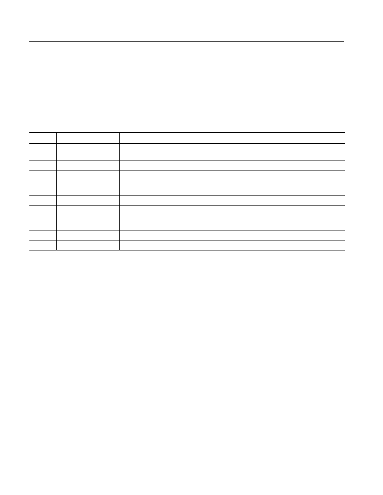
replacement parts. The following table describes each column in the parts list.
Parts List Column Descriptions
Column Column name Description
1 Figure & Index Number Items in this section are referenced by figure and index numbers to the exploded view
illustrations that follow.
2 Tektronix Part Number Use this part number when ordering replacement parts from Tektronix.
3 and 4 Serial Number Column three indicates the serial number at which the part was first effective. Column four
indicates the serial number at which the part was discontinued. No entries indicates the part is
good for all serial numbers.
5 Qty This indicates the quantity of parts used.
6 Name & Description An item name is separated from the description by a colon (:). Because of space limitations, an
item name may sometimes appear as incompl ete. Use the U.S. Federal Catalog handbook
H6-1 for further item name identification.
7 Mfr. Code This indicates the code of the actual manufacturer of the part.
8 Mfr. Part Number This indicates the actual manufacturer’s or vendor’s part number.
Abbreviations
Mfr. Code to Manufacturer
Cross Index
Abbreviations conform to American National Standard ANSI Y1.1--1972.
The table titled Manufacturers Cross Index shows codes, names, and addresses
of manufacturers or vendors of components listed in the parts list.
12
TLA72X, TLA7XM, & TLA7016 Benchtop Mainframe Rackmount Installation
Page 19

Replaceable Parts
Manufacturers cross index
Mfr.
code
0KB01 STAUFFER SUPPLY CO 810 SE SHERMAN PORTLAND, OR 97214--4657
06666 GENERAL DEVICES PO BOX 39100 INDIANAPOLIS, IN 48239
TK1943 NEILSEN MANUFACTURING INC 3501 PORTLAND RD NE SALEM, OR 97303
80009 TEKTRONIX INC 14150 SW KARL BRAUN DR
Manufacturer Address City, state, zip code
PO BOX 500
BEAVERTON, OR 97077--0001
TLA72X, TLA7XM, & TLA7016 Benchtop Mainframe Rackmount Installation
13
Page 20

Replaceable Parts
Replaceable parts list
Fig. &
index
number
Tektronix part
number
Serial no.
effective
Serial no.
discont’d
Qty Name & description
Mfr.
code
Mfr. part number
8--0 020-2369-XX 1 COMPONENT KIT:RACKMOUNT KIT 1R, SILVER GRAY;
--1 950-0991-00 2 HANDLE ALUMINUM BLK 80009 950-0991-00
--2 212-0157-00 14 SCREW,MACHINE:8--32 X 0.5,FLH,100 DEG,STL CDPL,T --15 0KB01 ORDER BY DESC
--3 407-4524-00 1 BRACKET:LEFT,RACKMOUNT,SILVER GRAY TK1943 407-4524-00
--4 212-0671-00 4 SCREW,MACHINE:10--32 X 0.625,FLH,100 DEG,STL,CD PL,
--5 407-4525-00 1 BRACKET:RIGHT, RACKMOUNT,SILVER GRAY TK1943 407-4525-00
--6 351-1010-00 1 GUIDE:RACK SLIDE EXTENSION BRACKET,CLOSED
--7 351-0800-00 1 GUIDE,SLIDE:CHASSIS TRACK, (PAIR) 06666 CTS--124
--8 386-6999-00 1 PLATE,LEFT:OFFSET SPACER,16 X 1.45,0.062 THICK AL TK1943 386-6999-00
-- 071-0897-01 1 MANUAL TECH: INSTRUCTIONS, TLA72X, TLA7XM, &
TLA72X, TLA7XM, & TLA7016
TORX
SLOT,9.7 X 8.1 INCHES (PAIR)
TLA7016 BENCHTOP MAINFRAME RACKMOUNT
INSTALLATION, DP
80009 020-2369-XX
0KB01 ORDER BY DESC
06666 B--814--2
80009 071-0897-01
14
TLA72X, TLA7XM, & TLA7016 Benchtop Mainframe Rackmount Installation
Page 21

Replaceable Parts
4
3
2
1
2
7
Figure 8: Rackmount assembly
5
2
6
8
7
2
6
g End of document g
TLA72X, TLA7XM, & TLA7016 Benchtop Mainframe Rackmount Installation
15
 Loading...