

Page 1

xx
016-1983-02, 016-1985-02, and 016-1988-02 and above
ZZZ
Rackmount Kits
Instructions
Revision A
Warning
The servicing instructions are for use by qualified personnel
only. To avoid personal injury, do not perform any servicing
unless you are qualified to do so. Refer to all safety summaries
before performing service.
www.tektronix.com
P075103901*
*
075-1039-01
Page 2

Copyright © Tektronix. All rights reserved. Licensed software products are owned by Tektronix or its subsidiaries
or suppliers, and are protected by national copyright laws and international treaty provisions.
Tektronix products are c overed by U.S. and foreign patents, issued and pending. Information in this publication
supersedes that in all previously published material. Specifications and price change privileges reserved.
TEKTRONIX and TEK are registered trademarks of Tektronix, Inc.
Contacting Tektronix
Tektronix, Inc.
14150 SW Karl Braun Drive
P.O . Bo x 50 0
Beaverto
USA
For product information, sales, service, and technical support:
n, OR 97077
In North America, call 1-800-833-9200.
World wi d e, vis it www.tektronix.com to find contacts in your area.
Page 3

Service safety summary
Only qualified personnel should perform se rvice procedures. Read this Service
safety summary and the General safety summary before performing any service
procedures.
Do not service alone. Do not perform internal service or adjustments of this
product unless another person capable of rendering first aid and resuscitation is
present.
Disconnec
disconnect the power cord from the mains power.
Use care when servicing with power on. Dangerous voltages or currents may exist
in this product. Disconnect power, remove battery (if applicable), and disconnect
test leads before removing protective panels, soldering, or replacing components.
To avoid electric shock, do not touch exposed connections.
t power. To avoid electric shock, switch off the instrument power, then
016-1983-xx, 016-1985-xx, and 016-1988-xx Kits 1
Page 4

Service s afety summary
2 016-1983-xx, 016-1985-xx, and 016-1988-xx Kits
Page 5

Kit Description
Products
This document supports Tektronix DPO7000/C, DPO70000/B/C/D/DX,
DSA70000/B/C/D, MSO70000/C/DX, AWG5000, and AWG7000 Series
instruments. The rackmount kit is a collection of parts that, once installed,
configure the instrument for mounting into a standard 19-inch equipment rack.
Kit 016-198
DPO7000/C Series All (configuration 1)
Kit 016-1
DPO70000/B/C/D/DX Series All (configuration 2)
DSA70000/B/C/D S eries All (configuration 2)
MSO70000/C/DX Series All (configuration 2)
Kit 016
AWG7000 Series All (configuration 3)
AWG5000 Series All (configuration 3)
mum Tool and Equipment List
Mini
Required tools and equipment Part number
Screwdriver, Phillips, #2 Standard tool
T-15 Torx tip
Screwdriver handle (magnetic) Accepts 1/4 inch hex-head driver tips
8-xx
985-xx
-1983-xx
Rackmount tray configuration:
Rackmount tray configuration:
Rackmount tray configuration:
Torx-driver tip for T-15 size screw heads
Kit Parts List
The following table lists the parts for each kit. You receive the parts for only the
kits you ordered.
Kit Quantity Part number Description
All 1 each 075-1039-01 Technical manual, instructions
016-1983-xx
016-1983-xx, 016-1985-xx, and 016-1988-xx Kits 3
1 each 016-1983-xx
1 each
2 each
–
–
Rackmount kit consisting of the following:
Rackmount kit
Rack, Trim plate
Page 6

Kit Description
Kit Quantity Part number Description
016-1985-xx
016-1988-xx
Warranted Characteristics
When the instrument is installed according to the instructions in this document, the
rackmounted instrument meets all warranted requirements listed in the instrument
specification. Instruments mounted using methods other than those described in
these instructions might not meet their warranted requirements.
For tables o f the warranted characteristics, see Specification in the specification
and performance verification manual that applies to your instrument model.
1 each 016-1985-xx
1 each
2 each
1 each 016-1988-xx
1 each
2 each
–
–
–
–
Rackmount kit consisting of the following:
Rackmount kit
Rack, Trim plate
Rackmount kit consisting of the following:
Rackmount kit
Rack, Trim p
late
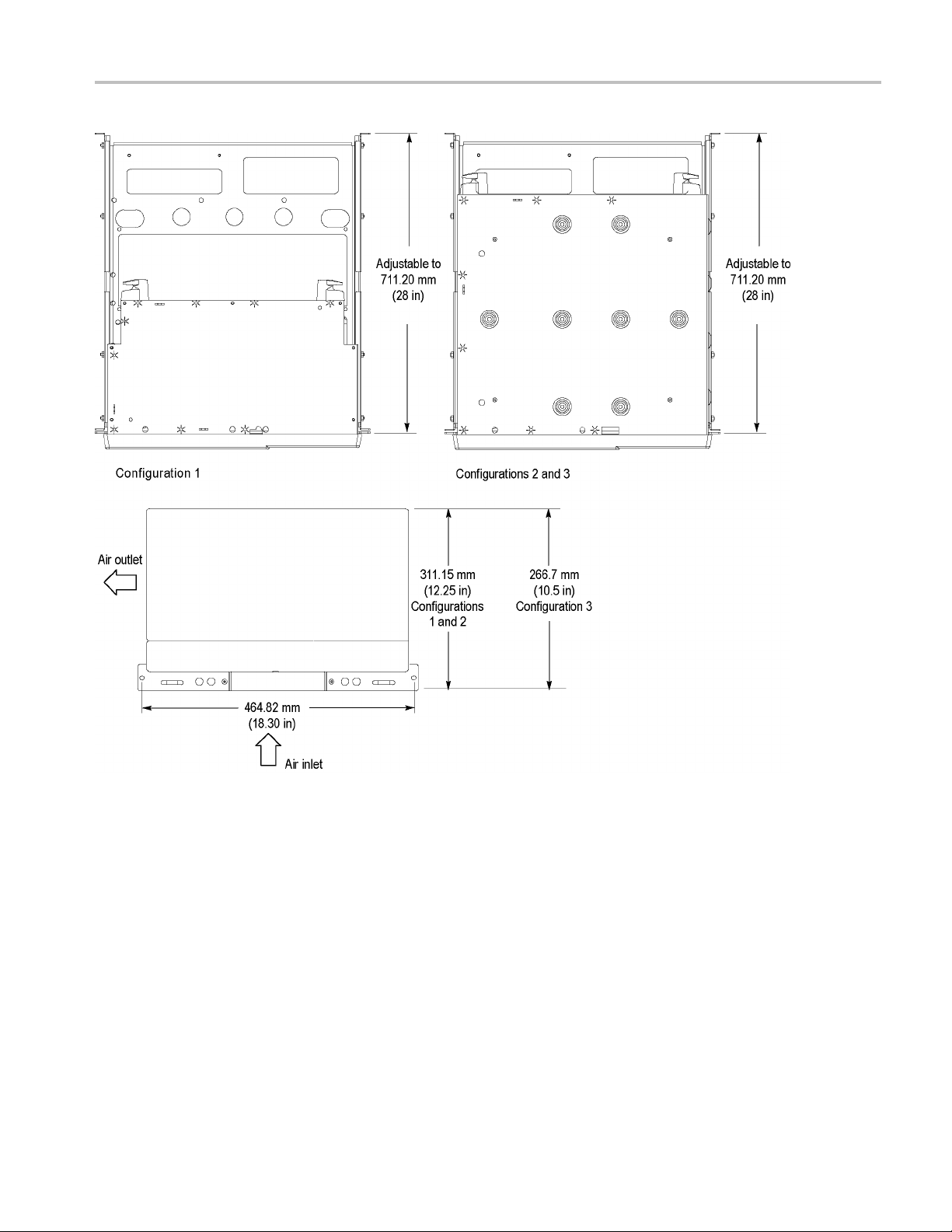
Cooling air enters on the bottom as shown in Figure 1. You assume the
responsibility to provide adequate cool air to meet the ambient temperature
requi
Clearance Requirements
The r
following clearance requirements:
CAUTION. Adhering to these requirements mounts the rack-adapted instrument
with enough clearance for air circulation and accommodation of the power
cord and mounting hardware. Failure to provide these clearances can result in
overheating and can cause the instrument to operate improperly or fail.
rements listed in the specifications.
ack in which the rack adapted instrument is mounted must provide the
figuration 1 and 2, at least 311.15 mm (12.25 in) of vertical space.
Con
Configuration 3, at least 266.7 mm (10.5 in) of vertical space.
A minimum width of 450 mm (17.717 in) between the left- and right-front
rails in the rack.
A minimum inside depth of at least 520.7 mm (20.5 in).
4 016-1983-xx, 016-1985-xx, and 016-1988-xx Kits
Page 7
Kit Description
Figure 1: Clearance requirements
016-1983-xx, 016-1985-xx, and 016-1988-xx Kits 5
Page 8

Installation Instructions
Installation Instructions
These instructions are for qualified service personnel who are familiar
with servicing the product. If you need further details for disassembling or
reassemblin
your nearest Tektronix, Inc., Service Center or Tektronix Factory Service for
installation assistance.
Remove
Remove the handle and trim as shown. (See Figure 2.)
g the product, refer to the appropriate product manual. Contact
Figure 2: Remove handle and trim
6 016-1983-xx, 016-1985-xx, and 016-1988-xx Kits
Page 9
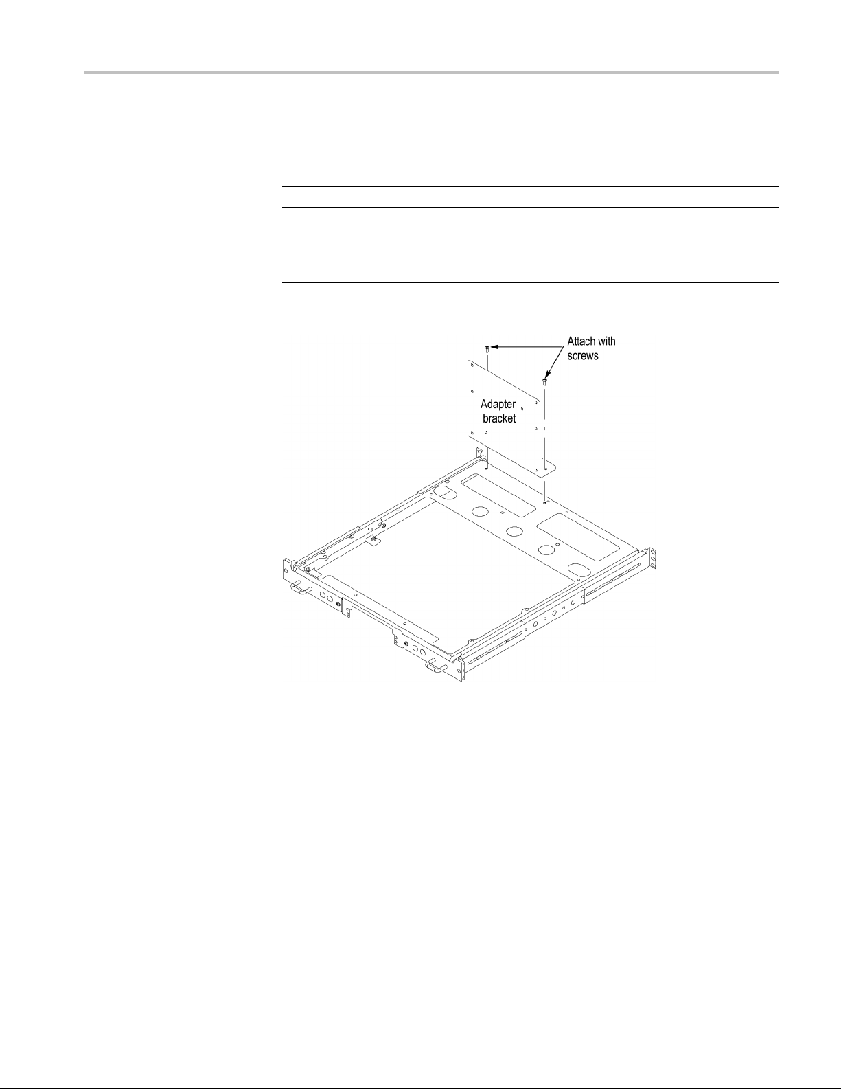
Install
Installation Instructions
Install the adapter bracket in your rack platform as shown in the following figures.
NOTE. Configuration 3 has additional spacer rails.
Install the adapter bracket.
NOTE. Install the adapter bracket only if you plan to install a Teklink Hub.
Figure 3: Assembly installation (configurations1and2shown)
016-1983-xx, 016-1985-xx, and 016-1988-xx Kits 7
Page 10

Installation Instructions
Figure 4: Assembly installation (configurations 1 and 2 shown)
8 016-1983-xx, 016-1985-xx, and 016-1988-xx Kits
Page 11
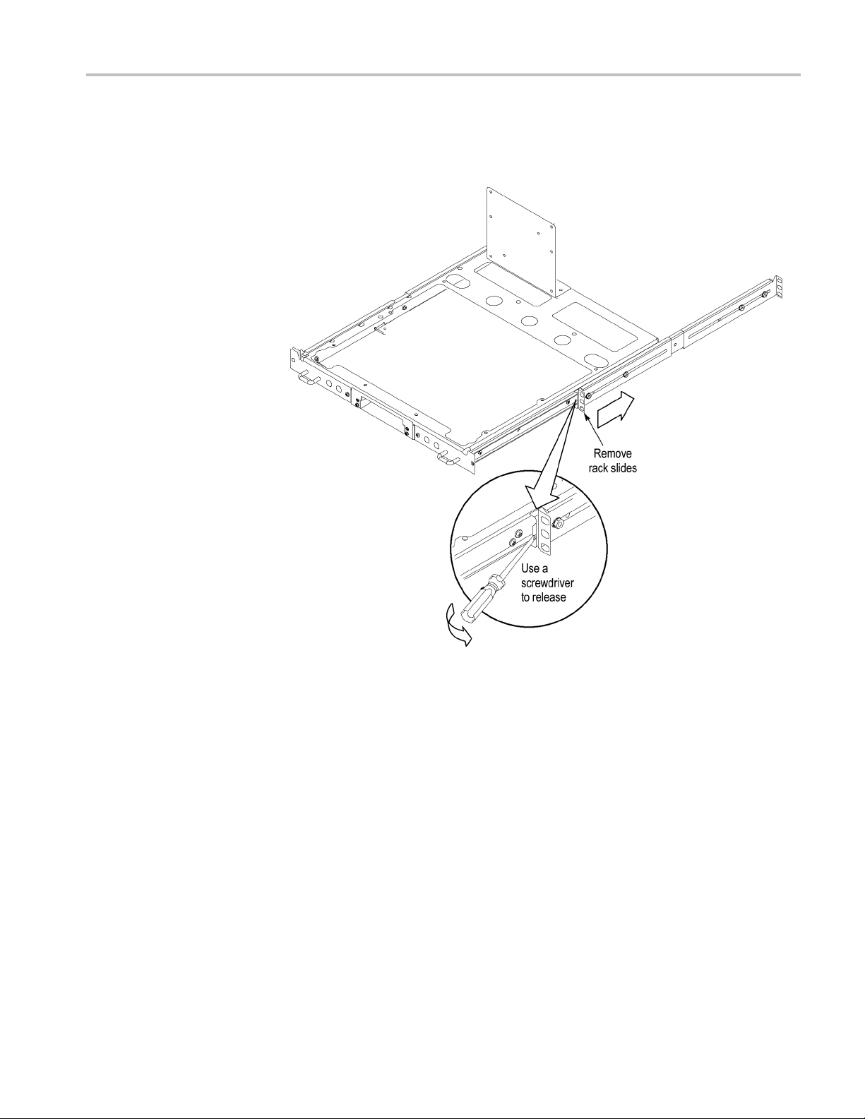
Reassemble
Installation Instructions
1. Remove the rack slides. (See Figure 5.)
Figure 5: Removing the rack slides (configurations 1 a nd 2 shown)
016-1983-xx, 016-1985-xx, and 016-1988-xx Kits 9
Page 12

Installation Instructions
2. Attach the rack
slides to your equipment rack. (See Figure 6.)
Figure 6: Installing the rail slides
10 016-1983-xx, 016-1985-xx, and 016-1988-xx Kits
Page 13

Installation Instructions
3. Install the rac
the slides as shown. (See Figure 7.)
k platform in your equipment rack by inserting the platform into
Figure 7: Installation of rack plate assembly in rack (top view) (configurations 1
and 2 shown)
WAR N ING. To avoid p ersonal injury, prevent the instrument from tipping or
ping, two or more people should install this instrument into the rack cabinet.
drop
After completing the installation procedure, verify that the instrument and the
rack cabinet will not tip forward while the instrument is in the extended position.
Do not leave the instrument extended when finished accessing the instrument.
016-1983-xx, 016-1985-xx, and 016-1988-xx Kits 11
Page 14

Installation Instructions
Figure 8: Installing the instrument on the rack plate
4. Install your instrument on the rack plate as shown. (See Figure 8.)
5. Install the power cord. Provide access to a power plug or mains d isconnect
switch for turning the instrument on/off.
6. Optionally install any cables you need connected to the instrument rear or
side panels.
7. Slide the instrument into the equipment rack.
12 016-1983-xx, 016-1985-xx, and 016-1988-xx Kits
Page 15

Installation Instructions
8. Install the app
ropriate trim plates as shown. (See Figure 9.)
Figure 9: Installation of trim plate
016-1983-xx, 016-1985-xx, and 016-1988-xx Kits 13
Page 16

Installation Instructions
Dimensions
14 016-1983-xx, 016-1985-xx, and 016-1988-xx Kits
Page 17

Installation Instructions
016-1983-xx, 016-1985-xx, and 016-1988-xx Kits 15
Page 18

Installation Instructions
16 016-1983-xx, 016-1985-xx, and 016-1988-xx Kits
Page 19

Installation Instructions
016-1983-xx, 016-1985-xx, and 016-1988-xx Kits 17
Page 20

Installation Instructions
18 016-1983-xx, 016-1985-xx, and 016-1988-xx Kits
Page 21

Installation Instructions
End of document
016-1983-xx, 016-1985-xx, and 016-1988-xx Kits 19
 Loading...