

Page 1
r
\
I,
I
!
INSTRUCTION
MANUAi.
Copyright
©
1970 by Tektronix,
Inc.,
Beaverton, Oregon. Printed
in
the
United States
of
America.
All
rights reserved. Contents
of
this
publication may
not
be reproduced
in
any form
without permission
of
the
copyright owner.
U.S.A.
and foreign Tektronix products covered
by
U.S.
and foreign patents and/or patents
pending.
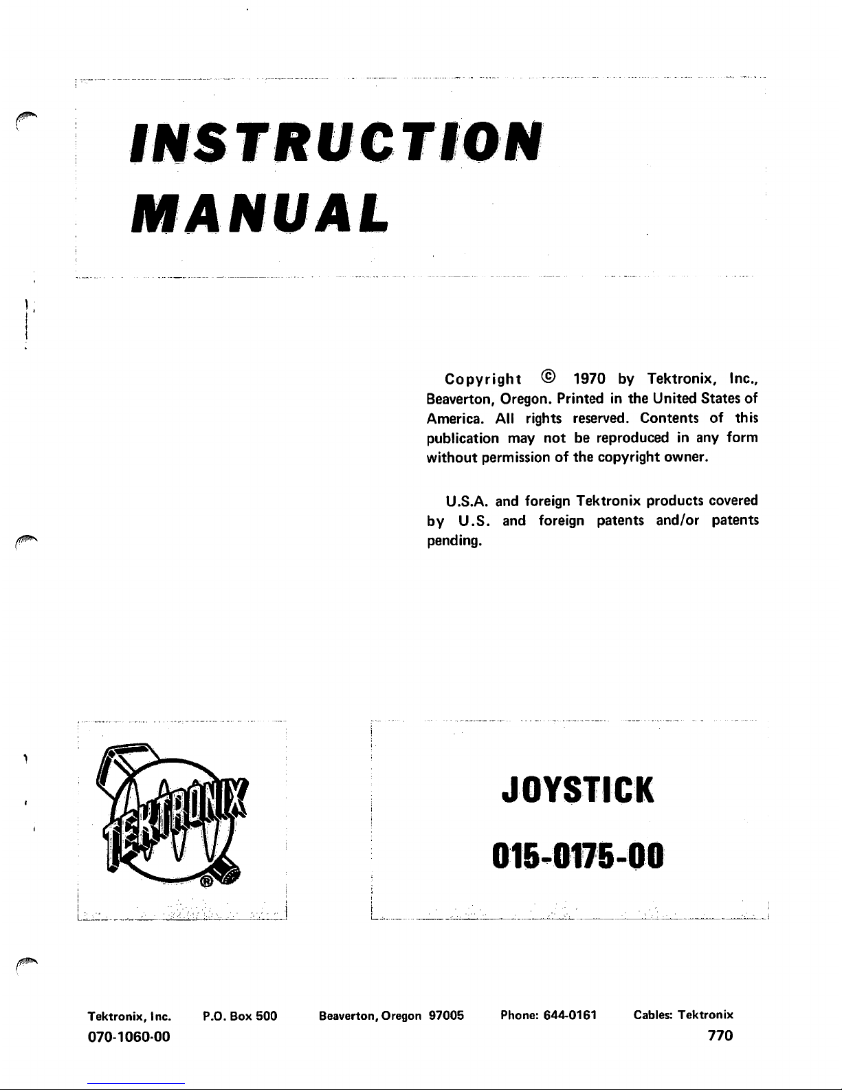
JOYSTICK
l,.:;_C.:.:-'--··"---···--··
·.::-
....
i
L...:
.....
--
--··----::......:.-·
---··
-·--~----~~::
__
~~..:....----~~---:__.~··
:__...;_~·
----~-~----..........:_:..____..___
__
J
Tektronix,
Inc.
P.O. Box
500
Beaverton, Oregon
97005
Phone: 644-0161 Cables:
Tektronix
070-1060-00
770
Page 2
·,,.:':
....
1.
I'
(~
..
·
·;·;··.
j
',
::\
I
!J;~,,]!:
!;:,,
___
.
__
..
:L
.
....
-,.
..
,--
.
l.
Joystick
,------~-~-----------------------
~·
~~
,·;
·,·
.
."
.I:.;·";'•;';:~··:
\
·;
=;:.·:·.:··
·. ·.
..
.:
;:'.
.·
.
,
..
·.
·~
··.:·-.:~
J
~-.·;.
,l:i;):
:./_:.:·;:~.\~(:~(=:'.\t3~?=:'.-.,\:·
.
.'·'
·.·.
. '
./·~···i;
·.I
.:
..
·.
·,·.:
·.
.
..
1 .
f ·
..
::;·::;
'.·
•,
;.
{;~
·;
.
·. ·.
. .
j
.
·./
...
-.·:.-
..
·.
·;·.-.-
........
:·
.
~
,=.
: ;
WARRANTY
All
Tektronix· instr-.ments
are warranted against
defective materials and workmanship for
one
year.
Tektronix transformers, manufactured
in
our
plant,
are warranted for the life
of
the instrument.
Any questions
. with
respect
to
the
warranty,
mentioned-
-.above:::
shQuld
be -taken .
~P
:
with-your
..
;.r
.
Tektronix
Field
Engineer
or
Representii1lve. ·
-
1:
.
I
--....:J--
All
requests ·
for.
repairs
and replacement parts
should
be·~rrected
to
the
Tektronix
~j~l~,:._,a,~rcer~rff·:
1
:
:·
representative in
your area.
This
proced~rll
1
wlll
itssure
1
·::
•
YR~--rtJ:le
fastest
possible service.
Please incll,\dlr·the '
inStfument ·Type (or
Part
Number) and SerlaL
or
,
_-::
-
·-Model
Number
with-all
requests for parts or service.
-
Spa~ifications
and price change privileges reserved.
r:
I
·_:.)
I
'\
j
•'
-~,
':
1,
i
.
·:
_
~
..:,
,I
!."
Page 3
SECTION
1
SECTION
2
SECTION
3
®
Joystick
015-0175-00
T
ABl.E
OF
CONTENTS
Page
SPECIFICATION
SECTION 3
CIRCUIT DESCRIPTION
(cont)
Introduction
1 X and Y Axis Positioning
Table 1·1 Electrical 1
Circuits
Table
1-2 Environmental 1
Table 1-3
Mechanical
1
SECTION
4
MAINTENANCE
Standard Accessories
1
Information
Preventive Maintenance
OPERATING INSTRUCTIONS
Corrective
Maintenance
General
2
Instrument Controls
2
SECTION
5
ELECTRICAL PARTS LIST
Connectors
2
Abbreviations and
Symbols
Calibration
2
Parts
Ordering
Information
Electrical Parts
List
CIRCUIT DESCRIPTION
SECTION
6
MECHANICAL PARTS LIST
General
3
Circuit Operation
Mechanical Parts Illustrations
General
3
Mechanical Parts
List
Ready Indicator
3
CURSOR BRIGHTNESS
and
IG
OFF
SECTION
7
DIAGRAMS
Control
3
Diagram
Abbreviations and
symbols
used
in
this
manual
are based on
or
taken
directly
from
IEEE
Standard
260 "Standard Symbols
for
Units", MIL-STD·12B
and other standards
of
the
electronics industry.
Change
information, if any,
is
located
at
the
rear
of
this manual.
Page
3
4
4
4
Page 4
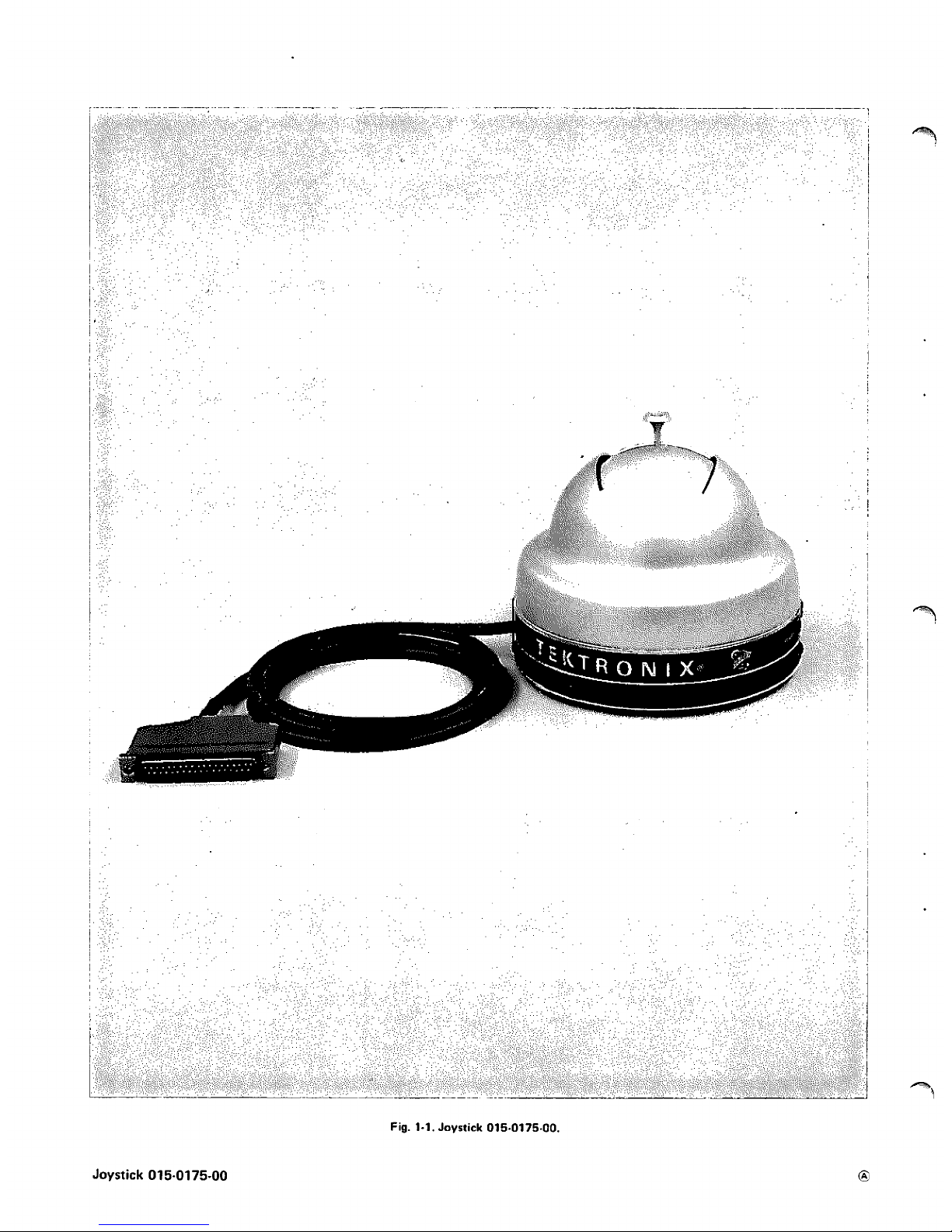
Fig. 1·1.
Joystick
015-0175-00.
Joystick 015-0175-00
Page 5
Joystick
015-0175-00
SECTION
1
SPECIFICATION
Introduction
The Tektronix
015-0175-00
Joystick
is
an
input
device
intended for use with the Tektronix
4901
Interactive
Graphic Unit.
The
Joystick provides X and Y Axis
posi-
tioning voltages from high resolution sensing elements using
a single control handle. An opening
in
the
enclosing shroud
limits travel of
the
control handle.
The
Joystick can be
calibrated
so
the perimeter
of
the
opening
in
the
shroud
corresponds
to
the
limits
of
the
display area
on
the
T4002
Terminal Display
Unit,
or some portion
of
the
display area.
TABLE
1-2
ENVIRONMENTAL
TABLE
1-1
ELECTRICAL
Parameter
Performance Limits
Resolution
(X
and
Y)
Within one addressable
point
of
a
previously stored point.
Parameter
Temperature
Operating Range
Storage Range
Altitude
Operating Range
Storage Range
Transportation Test
Parameter
Joystick Excursion
Side-to-Side
Performance Limits
0°C
to
+50°C.
-40°C
to
+65°C.
To
15,000
feet.
To
50,000
feet.
Not specified. Tested to
NTSC pro-
cedure
1A
with a
24
inch
drop.
TABLE
1-3
MECHANICAL
Performance Limits
66° within 4°.
Corner-to-Corner 94° within 4°.
CURSOR BRIGHT- +6 volts
or
less,
to
at
least +14
NESS Voltage
Output
Range
volts.
SEEK
Input
Voltage +2.4 volts
to
+5.5 volts.
Range
1
ea.
®
Finish
Dimensions
Height
Diameter
STANDARD
ACCESSORIES
Instruction Manual
Anodized Aluminum.
2
pounds,
8
ounces.
5.425
inches.
070-1060-00
1
Page 6
Joystick 015-0175-00
SECTION
2
OPERATING
INSTRUCTIONS
OPERATING INSTRUCTIONS
General
To
effectively
use the
015-0175-00
Joystick, the
opera-
tion and
capabilities
of
the instrument must be known. This
section describes the operation of the instrument controls
and indicators and gives the adjustment procedure
neces·
sary
to
modify instrument
calibration
to
meet specific
needs.
Instrument Controls
CURSOR BRIGHTNESS and
IG
OFF.
This
is
a
dual
purpose
control
that
varies the intensity of
the
crosshair
cursor
display
and,
in
the switch detent position
of
the
control, disables the
Interactive
Graphic
Unit
to
which the
Joystick
is
connected.
Control Handle. This single
handle located
in
the square
cutout
area of the
enclosing
shroud
is
mechanically connec·
ted to the potentiometers
that
supply the X and Y Axis
positioning voltages. With the Joystick situated so the
READY
light
and
CURSOR BRIGHTNESS/IG OFF con-
trol
face the user, pushing the
control handle away
will
position the crosshair cursor
display
toward the upper part
of the
display area. Setting
the
control handle
to
the user's
left will position
the
crosshair cursor display
to
the
left
part
of the
display area.
The
perimeter of
the
cutout
area
in
the
enclosing
shroud corresponds
to
the
limits
of the
display
area of the
T4002
Graphic Computer Terminal Display
Unit.
READY Light. The READY light
indicates, when it
is
lit,
that the
Interactive
Graphic
Unit
to
which
the
Joystick
is
connected
is
ready
to
accept new X and Y Axis positional
information.
The
READY
light
can
only
be
lit
when
the
CURSOR BRIGHTNESS/IG OFF control
is
in
some
posi·
tion other than
IG
OFF.
Connectors
P
1000
is
a 37
-pin
connector used
to
connect the
Joy-
stick
to
the
Interactive
Graphic
Unit
being used.
Construc-
tion of the plug eliminates the possibility of improperly
installing it. A
locking
device on
PlOOO
securely attaches it
to the mating connector
on
the
Interactive Graphic
Unit,
and eliminates accidental disconnection or
removal.
Calibration
Adjustments are
accessible
on
the bottom panel
of the
Joystick
to
facilitate calibration.
The Joystick,
as
it comes
2
from the factory,
is
calibrated
so the opening
in
the en-
closing shroud corresponds to the
limits of the display area
of the
Terminal Display Unit.
However, the instrument can
be
recalibrated
to
make the opening
in
the shroud
corres·
pond to some
lesser
portion of the
display
area with no
detrimental
effect
on
operation. Refer
to
the
following pro·
cedure for instrument recalibration.
1.
Install
the
4901 Interactive
Graphic
Unit
in
the
Aux·
iliary
Compartment of
the
T4002 Graphic Computer
Ter·
minal and connect the
015-0175-00 Joystick to the
4901.
2.
Obtain
a crosshair cursor
display
on
the Terminal
Display Unit.
3.
Set the
control
hand
le
of the Joystick
to
position the
intersection
of
the crosshair cursor display
to
the
upper-
most part
of
the
display
area.
4.
ADJUST-Y
Gain adjustment R12
to
set the inter·
section of the crosshair cursor
display
to
the
vertical posi·
tion desired.
5. Set
the
control handle
of the Joystick
to
position the
intersection of the crosshair cursor display
to
the
lowest
part of the display area.
6.
ADJUST-Y
Offset adjustment R 18
to
set the
inter·
section of the crosshair cursor
display
to
the
vertical posi-
tion desired. There
will
be interaction between step 4 and
step 6. Readjust
until
there
is
no further interaction.
7.
Set
the
control handle
of the Joystick
to
position the
intersection
of
the crosshair cursor display
to
the extreme
right-hand part of the display
area.
8.
ADJUST
-X
Gain adjustment R4
to
set the
inter·
section
of
the
crosshair cursor
display
to
the
horizontal
position desired.
9.
Set
the control handle of the Joystick
to
position the
intersection of the crosshair cursor
display
to
the extreme
left·hand
part
of
the
display
area.
10. ADJUST
-X
Offset
adjustment R 15
to
set the
inter-
section of
the
crosshair cursor
display
to
the
horizontal
position desired. There
will
be interaction between step 8
and step
10. Readjust
until there
is
no further interaction.
11. Recheck
the
Y Axis adjustments.
®
Page 7

Joystick
015-0175-00
SECTION
3
CIRCUIT
DESCRIPTION
General
This section contains a description
of
the circuitry used
in
the
015-0175-00
Joystick. The description begins with a
discussion of the
general
function
of
the Joystick circuitry,
then describes each circuit
in
detail.
Refer to
the
schematic
diagram
in
the Diagrams section throughout
the
following
circuit description for
electrical values
and relationships.
CIRCUIT OPERATION
General
The
015-0175-00
Joystick
is
primarily
a source of two
precisely variable voltages.
These
voltages, when used with
the Tektronix
4901 Interactive
Graphic
Unit,
provide X
and Y Axis positioning. The
amplitude
and
level
of these
voltages
can be adjusted
to
make
the
perimeter of
the
control handle
opening correspond
to
any desired portion
of
the
viewing area of the
T4002 Terminal Display Unit.
The Joystick
also
contains a
CURSOR BRIGHTNESS
control,
a graphics
disabling switch, and a READY
indicator lamp.
READY
Indicator
When the READY
lamp
is
on, it indicates
that
the
Inter-
active Graphic
Unit
to
which the Joystick
is
connected
is
ready
to
accept new X and Y Axis positional
information.
In
this state, a positive
level
called SEEK
is
applied
to
the
base
of
transistor
02
through R9. This positive
level
turns
on
02,
causing a negative change
in
the
collector
circuit.
This negative
level
biases transistor
05
into saturation and
applies
five
volts
to
READY indicator lamp DS5.
CURSOR BRIGHTNESS
and
IG
OFF Control
Variable
resistor
R1
varies the
level
called CURSOR
BRIGHTNESS
between +5
volts
and +15
volts approxi-
mately.
In
the
IG
OFF
position of the
CURSOR BRIGHT-
NESS control,
switch
S1
opens and transistor
02
is
biased
on. The
collector
of
02
steps negative and the
level
called
OFF
inhibits
the
Interactive
Graphic
Unit.
X and
V
Axis Positioning Circuits
R3 and R
11
are high
resolution,
conductive
plastic-
element
potentiometers. Both are
mechanically
connected
to
a single control handle
and provide X and Y axis
posi-
tioning voltages
to
the
4901 Interactive
Graphic
Unit.
R4
and R 12 adjust the range of
voltages
that
R 3 and R
11
can
provide. R 15 and R 18 provide
DC
offset adjustments for
the
minus
differential
inputs
to
the
4901.
3
Page 8

Joystick
015-0175-00
SECTION 4
MAINTENANCE
Information
This section contains information
that
will
aid
in
keeping the
015·0175-00 Joystick operating
at
its peak
performance. Parts identification and soldering
techniques
are
included
where necessary.
Preventive Maintenance
Design
of
the
015-0175-00
Joystick permits a minimum
of preventive maintenance.
Occasional cleaning of the
instrument may be
accomplished
using a
cloth
or
dry paint
brush to remove
loose
dirt. Hardened dirt can be removed
with a paint
brush,
cotton-tipped swab or
cloth
dampened
with a water and
mild
detergent
solution.
To
clean
the
interior, use
low-velocity
compressed air to
blow
off the
accumulated
dust.
High
velocity
air streams
should
be
avoided
to
prevent damage
to
components.
Periodic preventive maintenance checks on the
transis·
tors used
in
the unit are not recommended. The circuits
within
the
unit generally provide
the
most satisfactory
means of checking transistor
usability.
Corrective Maintenance
Replacement
of some parts
in
the unit
should
be done
by
following a definite procedure. Some procedures, such
as
soldering
and replacing
components on the circuit board
are
outlined
in
this portion of the
manual.
Use
ordinary
60/40
solder
and a 35·
to
40-watt pencil
type soldering iron on the circuit board. The tip of the iron
should
be
clean
and
properly
tinned for best heat transfer
to
the
solder
joint. A higher wattage soldering iron may
separate the etched wiring from the base material.
The
following
technique
should
be used
to
replace
a
component on the circuit board. Most components can be
replaced
without removing the board from the unit.
1.
Grip the component
lead
with
long-nosed pliers.
Touch the
soldering
iron
to
the
lead
at
the
solder connec·
tion. Do
not
touch the
soldering
iron tip
directly
on the
board,
as
it may damage the board.
4
2. When
the
solder
begins
to
melt, pull
the lead
out
gently.
This should leave
a
clean hole
in
the
board.
If not,
the
hole
can be
cleaned
by reheating the
solder
and
placing
a sharp object, such as a toothpick
or
pointed
tool,
into the
hole
to
clean
it out.
3. Bend the
leads
of
the new component
to
fit
the
holes
in the board.
Cut
the
leads
of the
new
component
to
the
same
length
as
those of the
old
component.
Insert
the
leads
into the board
until
the
component
is
firmly
seated against
the
board,
or
as
positioned
originally.
If
it does
not
seat
properly,
heat the joint,
and
gently
press the component
into
place.
4.
Apply
the
iron and a
small
amount of
solder
to
the
connection
to
make a firm
solder joint.
To
protect
heat·
sensitive components,
hold
the
lead
between
the
com-
ponent body and the
solder
joint with a pair of
long-nose
pliers
or
other heat sink.
5. Clip
the excess
lead
that
protrudes through the
board.
Lamp drive
Circuit
Board
Fig.
4-1.
Component
location in
the
Joystick.
R11
Ready
Light
®
Page 9

6.
Clean
the area around the soldered connection with
flux·remover solvent
to
maintain good
environmental char-
acteristics and appearance.
Be
careful
not
to remove
infor·
mation printed on the board.
All
electrical
and mechanical part
replacements
can be
obtained through your
local Tektronix
Field
Office or
rep-
resentative. However, many of the standard
electronic com-
ponents can be obtained
locally
in
less
time than
is
required
Joystick
015-0175-00
to
order them from Tektronix,
Inc.
Before purchasing
or
ordering
replacement parts,
check the parts
lists
for
value,
tolerance,
rating and description.
Some
parts are manufactured or
selected
by
Tektronix
to
satisfy particular requirements,
or
are manufactured for
Tektronix to
out
specifications. These and most
mechanical
parts
should
be ordered through your Tektronix
Field En-
gineer or Field
Office.
Fig.
4-2.
Lampdrive Circuit Board.
®
5
Page 10

NOTES
Page 11

PARTS
LIST
ABBREVIATIONS
BHB
binding head brass
int
internal
BHS
binding head
steel
lg
length
or
long
cap.
capacitor
met.
metal
cer
ceramic
mtg
hdw mounting hardware
comp
composition
OD
outside diameter
connector
OHB
oval
head brass
conn
CRT
cathode-ray tube
OHS
oval
head
steel
csk
countersunk
P/0
part of
PHB
pan head brass
DE
double
end
PHS
pan head
steel
dia
diameter
piste
plastic
div
division
PMC
paper,
metal
cased
""
elect.
electrolytic
poly
polystyrene
EMC
electrolytic, metal
cased
precision
prec
EMT
electrolytic, metal tubular
PT
paper, tubular
ext
external
PTM
paper or plastic, tubular,
molded
F&I
focus
and
intensity
RHB
round
head brass
FHB
flat head brass
RHS
round
head
steel
FHS
flat head
steel
SE
single end
Fil
HB
fillister head brass
SN
or S/N
serial number
Fil
HS
fillister
head
steel
Sor
SW
switch
h
height or
high
TC
temperature compensated
hex.
hexagonal
THB
truss
head brass
HHB
hex
head brass
thk
thick
HHS
hex
head
steel
THS
truss
head steel
HSB
hex
socket brass
tub.
tubular
HSS
hex
socket
steel
var
variable
ID
inside diameter
w
wide or width
inc
i
nca
nd
escent
WW
wire-wound
~·
Page 12

PARTS
ORDERING
INFORMATION
Replacement parts
are
available
from
or
through your
local
Tektronix,
Inc.
Field
Office or representative.
Changes
to Tektronix instruments
are
sometimes
made
to accommodate improved
components
as
they become
available,
and
to
give you the benefit
of
the
latest
circuit
improvements developed
in
our engineering department.
It
is
therefore important, when
ordering parts, to include the following information
in
your order:
Part
number, instrument
type
or
number, serial
or
model number,
and
modification number
if
applicable.
If
a port you
have
ordered has been replaced with a new
or
improved part, your
local
Tektronix,
Inc.
Field
Office
or representative
will
contact you concerning any change
in
part number.
xooo
oox
*000.0000.00
Use 000.0000·00
SPECIAL
NOTES
AND
SYMBOLS
Part
first
added
at
this serial number
Part
removed ofter this serial number
Asterisk preceding Tektronix
Port
Number indicates manufactured by
or
for Tektronix,
Inc.,
or reworked or checked components.
Part
number indicated
is
direct replacement.
Page 13

r-
Joystick
015-0175-00
SECTION
5
ELECTRICAL PARTS LIST
Values
are
fixed
unless
marked Variable.
Serial/Model No.
Ckt.
No.
Tektronix
Part No.
Eff
Disc
Description
DS5
150-0045-00
PlOOO
131-0422-00
Resistors
are fixed, composition,
+
10%
RP
R3
R4
Rll
R12
Rl4
Rl5
Rl7
R18
SF
Q2
Q5
Q8
311-0645-00
311-1
077
-00
311-0086-00
311-1077
-00
311-0086-00
321-0258-00
311-0328-00
321-0258-00
311-0328-00
Wired
or
Unwired
311-0645-00
*670-0365-00
*151-0190-02
*151-0208-01
*151-0190-02
CHASSIS
Bulb
Incandescent
#685
Connector
Receptacle, electrical,
37-pin,
male
Resistors
unless
otherwise indicated.
50
kn, Var
1 kn,
Var
2.5
kn,
Var
l
kn, Var
2.5
kn,
Var
4.75
kn
1/a
W
Pree
1
kn, Var
4.75kn
1/e
w
Pree
1 kn, Var
Switch
LAMPDRIVE
Circuit
Board
Assembly
Complete
Board
Transistors
Silicon
Silicon
Silicon
NPN
PNP
NPN
T0-92
2N3904
T0-5
2N4036
T0-92
2N3904
Resistors
Resistors
are fixed, composition,
+
10%
unless
otherwise indicated.
R2
R6
R7
R9
317-0103-00
317-0103-00
317-0471-00
317-0472-00
'Furnished
as
a
unit
with
S
1.
'Furnished
as
a
unit
with
Rt
.
®
10
kn
10
kn
470n
4.7
kn
1/a
W
1/e
w
1/a
w
1
/a
W
1%
1%
5%
5%
5%
5%
6
Page 14

FIGURE
AND
INDEX
NUMBERS
Items
in
this section
are
referenced by figure
and
index numbers to the illustrations which
appear
either on the back
of
the diagrams
or
on pullout
pages
immediately
following
the
diagrams of the instruction manual.
INDENTATION
SYSTEM
This
mechanical parts list
is
indented to indicated item relationships. Following
is
an
example of the indentation system used
in
the Description column.
Assembly
and/or
Component
Detail
Part
of Assembly and/or
Component
mounting hardware
for
Detail
Part
Parts
of
Detail
Part
mounting hardware
for
Parts
of Detail
Part
mounting
hardware
for
Assembly and/or
Component
Mounting
hardware
always
appears
in
the
same
indentation
as
the item it mounts,
while the detail parts
are
indented to the right. Indented items
are
part
of,
and
included
with, the next higher indentation.
Mounting hardware must
be
purchased separately,
unless otherwise specified.
PARTS
ORDERING
INFORMATION
Replacement parts
are
available
from
or
through your
local
Tektronix,
Inc.
Field Office
or
representative.
Changes
to
Tektronix instruments
are
sometimes
made
to
accommodate
improved
components
as
they become
available,
and
to give you the benefit
of
the latest circuit
improvements developed
in
our
engineering department.
It
is
therefore important, when
ordering parts, to
include
the following information in your order: Part number, instru-
ment type
or
number, serial
or
model number,
and
modification number
if
applicable.
If
a
part
you have ordered has been replaced with a new
or
improved part, your
local Tektronix,
Inc.
Field
Office
or
representative
will
contact you concerning
any
change
in
part
number.
Change information,
if
any,
is
located
at
the rear of this manual.
ABBREVIATIONS
AND
SYMBOLS
For
an
explanation
of the abbreviations
and
symbols
used
in
this section,
please
refer
to the
page
immediately preceding the Electrical Parts
List
in
this instruction
manual.
Page 15

Fig. &
Index
Tektronix
No.
Part No.
1-1
380-0213-01
------
-2
211-0584-00
-3
380-0214-01
------
.4
214-1422-00
-5
343-0144-00
------
-6
213-0034-00
-7
-
...
. - - -
------
-8
210-1118-00
P"
-9
210-1015-00
·."
-10
210-0600-00
-11
407-0813-01
-12
376-0108-00
------
213-0126-00
-13
407-0812-00
-
.. -.. ..
-
-14
211-0097-00
-15
136-0279-00
-16
366-0341-00
------
213-0140-00
-17
------
------
-18
210-0583-00
210-0940-00
-19
210-0046-00
Joystick
015-0175-00
SECTION 6
MECHANICAL
PARTS LIST
Serial/Model No.
Eff
Oise
FIGURE
1 EXPLODED
Q
t
y
12345
Description
HOUSING, controller, outer
mounting hardware:
(not
included w/housingJ
3
SCREW,
6-32 x 0.25
inch,
CHS
HOUSING, controller, inner
mounting hardware:
(not
included w/housingJ
LEVER,
controller
CLAMP,
cable,
0.125
inch
diameter
mounting hardware:
(not
included w/clampJ
SCREW,
thread forming,
#2
x
0.312
inch,
PHS
2
RESISTOR,
variable, w/hardware
mounting hardware
for
each:
(not
included w/resistorJ
WASHER,
plastic,
0.253
ID
x
0.625
inch
OD
WASHER,
spring tension,
0.254
ID
x
0.50
inch
OD
NUT,
hex.,
0.375-32 x 0.562
inch
BRACKET,
w /post
COUPLING,
variable resistor
coupling includes:
2
SETSCREW,
6-32 x 0.25
inch,
HSS
l
BRACKET,
component mounting
mounting hardware:
(not
included w/bracket)
2
SCREW,
4-40 x 0.312
inch,
PHS
LIGHT,
indicator, w/hardware
KNOB,
charcoal-CURSOR
BRIGHTNESS
knob
includes:
2
SETSCREW,
2-56 x 0.094
inch,
HSS
l
RESISTOR,
variable
mounting hardware:
(not
included w/resistorJ
NUT,
hex.,
0.25-32 x 0.312
inch
WASHER,
flat,
0.25
ID
x
0.375
inch
OD
WASHER,
lock,
internal,
0.261
ID
x
0.40
inch
OD
7
Page 16
Mechanical
Parts
Ust-Joystick
015-0175-00
Fig.
&
Index
Tektronix
No. Part No.
1-20
670-0365-00
---·--
388-1705-00
-
..
-
..
- -
-21
211-0014-00
-22
166-0025-00
-23
343-0003-00
--·---
-24
212-0023-00
-25
210-0008-00
-26
210-0863-00
-27
..
- -
-
.
-
-
..
...
- - -
210-0583-00
210-0940-00
-28
210-0223-00
-29
..
-
...
-
.
-
..............
-30
210-0583-00
-31
210-0940-00
-32
210-0046-00
.33
348-0261-00
.34
175-1157-01
-35
200-0779-01
-36
200-0660-00
-37
131-0975.00
-38
131-0422.00
.39
432-0070-01
-40
348-0037-00
------
-41
211-0097-00
-42
334-1584.00
070-1060-00
8
FIGURE
1
EXPLODED
I
cont l
Serial/Model
No.
Eff
Disc
Q
t
y
12)45
Description
CIRCUIT
BOARD
ASSEMBLY-LAMPDRIVE
circuit
board assembly
includes:
CIRCUIT
BOARD
mounting
hardware:
(not
included w/circuit board assembly)
2
SCREW,
4-40
x
0.50
inch,
PHS
2
TUBE,
spacer,
0.25
inch
long
CLAMP,
coble, plastic,
0.25
inch
diameter
mounting
hardware:
(not
included w/clamp}
SCREW,
B-32
x
0.375
inch,
PHS
WASHER,
lock,
internal,
#8
WASHER,
D shape,
0.191
ID
x
0.515
inch
RESISTOR,
variable
mounting
hardware:
(not
included w/resistor}
NUT,
hex.,
0.25-32
x
0.312
inch
WASHER,
flat,
0.25
ID
x
0.375
inch
OD
LUG,
solder,
0.25
ID
x
0.437
inch
OD,
SE
3
RESISTOR,
varioble
mounting
hardware
for
each:
(not
included w/resistor)
NUT,
hex.,
0.25-32
x
0.312
inch
WASHER,
flat,
0.25
ID
x
0.375
inch
OD
WASHER,
lock,
internal,
0.261
ID
x
0.40
inch
OD
1
GROMMET,
plastic
ft
CABLE,
special
purpose,
electrical,
6.50
feet
1
CABLE
NIPPLE,
1.93
inches
long
1
COVER,
connector,
w /hardware
1
LOCK,
sliding,
connector,
w/hardwore
1
CONNECTOR,
receptacle,
37
pin
1
BASE,
controller,
w
/variable
resistor
bracket
4
FOOT,
rubber,
0.1
B8
inch
h,
0.50
inch
diameter
mounting
hardware
for
each:
(not
included
w/foot)
SCREW,
4-40
x
0.312
inch,
PHS
LABEL,
identification
STANDARD
ACCESSORIES
MANUAL,
instruction
(not
shown}
®
Page 17

JOYSTICK 015-0175-
0CJ.t..
Page 18
+
Fig
&
Index Tektronix
Serial/Model
No.
No.
Part No.
Eff
Disc
2-
065-0136-00
1
004-0639-00
-2
004-0539-00
-3
004-1
078-00
-4
004-0211-00
t
Description
y 1
2345
1
1
1
2
CARTON
ASSEMBLY
for
015-0175-00
carton assembly includes:
CARTON
PAD
SET
3 piece
PAD
SET
2 piece
END
CAP
plastic
JOYSTICK 015-0175-00
+
Page 19

SECTION
7
DIAGRAM
The
following
special symbols
are
used
on the diagrams:
~
Screwdriver adjustment
Front
or
rear-panel
control
or
connector
y
Connection soldered
to
circuit
board
'
VV'\.----41-----
1
./
Blue-line encloses components located on
~
f
circuit
board
r-
Page 20

+
10
IIG.OFF
SI
,--------------,
I I
i
t
I
I
D
+
F
R'2
I
OK
Q2
E
+sv
,__
___
i
______
_
______
__.,,__
____________
~
I
2sl
:
CB
RI
CURSOR
I
I
'::>OK
BRIGHT
N
ESS
+ I
!::>
V
f--
2
-
7
-------4,__.,..
+I
S
V
+ I
SV
~--~R4
23
+
X
f--------.<R3
IK
26
2.'::>K
"X
G.AIN
A
R7
470
Rb
I
OK
QS
D
SS
I
READY
I
QB
SEE
K
~-------------------f--
~!V'v
---1~
LAMPDRI
VE
CI
RCUIT
BOARD
I
18
4
+ISV
.---P<R
l 2
2.!::>K
+V
~----
-
-<RI
I
\y
G.AIN
22
3
OIS-0175-00
IK
+l'::>V
R l 7
47'::>K
®
+IS
V
R l 4
4
?SK
NO
T
ES.
I
SEE
PARTS
LI
ST
FOR
SEMIC
O
NDU
C
TOR
TYPES
2.7coMMON
G.ND
JOYST
CK
670
 Loading...